

Page 1
Nice
RB500HS
RB600
RB1000
For sliding gates
EN - Instructions and warnings for installation and use
Page 2

Page 3

CONTENTS
GENERAL WARNINGS:
SAFETY - INSTALLATION - USE 2
1 - PRODUCT DESCRIPTION AND INTENDED USE 3
2 - OPERATING LIMITS 3
3 - INSTALLATION 4
4 - ELECTRICAL CONNECTIONS
4.1 - Types of electrical cables 10
4.2 - Electrical cable connections 10
5 - STARTING THE AUTOMATION AND CHECKING THE
CONNECTIONS
5.1 - Connecting the automation to the mains electricity 12
6 - TESTING AND COMMISSIONING
6.1 - Testing 12
6.2 - Commissioning 13
7 - PROGRAMMING
GLOSSARY 14
7.1 - Programming 14
7.2 - Level 1 functions (ON-OFF functions) 14
7.3 - Level 1 programming (ON-OFF functions) 15
7.4 - Level 2 functions (adjustable parameters) 16
7.5 - Level 2 programming (adjustable parameters) 17
7.6 - Recognition of devices 18
7.7 - Recognition of the gate length 18
7.8 - Checking gate movement 18
7.9 - Pre-set functions 19
7.10 - Radio receiver 19
8 - FURTHER DETAILS
8.1 - Adding or removing devices 19
8.2 - FT210B photosensor 20
8.3 - ROBUS in “Slave” mode 21
8.4 - Recognition of other devices 22
8.5 - Connecting the Oview programmer 22
8.6 - Special functions 22
8.7 - Connecting other devices 24
8.8 - Accessories 24
9 - DIAGNOSTICS 24
9.1 - Fault log list 25
9.2 - Diagnostics and signals 25
9.2.1 - Flashing light signals 25
9.2.2 - Control unit signals 26
10 - PRODUCT DISPOSAL 27
11 - MAINTENANCE 28
12 - TECHNICAL SPECIFICATIONS 28
CE DECLARATION OF CONFORMITY 29
User manual (end user version) 31
English – 1
Page 4

GENERAL WARNINGS: SAFETY - INSTALLATION - USE (original instructions in Italian)
The following warnings are taken directly from the Regulations and apply, as far as possible, to the product described herein
CAUTION Important safety instructions. Observe all the instructions as improper installation may cause serious damage
CAUTION Important safety instructions. It is important to comply with these instructions to ensure personal safety. Store
these instructions
• Before commencing the installation, check the “Product technical specications”, in particular whether this product is suitable for automating
your guided part. Should it be unsuitable, DO NOT proceed with the installation
• The product cannot be used before it has been commissioned as specied in the “Testing and commissioning” chapter
CAUTION According to the most recent European legislation, the implementation of an automation system must comply with
the harmonised standards set forth in the Machinery Directive in force, which allow for declaring the presumed
conformity of the automation. On account of this, all operations regarding connection to the mains electricity, as
well as product testing, commissioning and maintenance, must be performed exclusively by a qualied and skilled
technician!
• Before proceeding with the product’s installation, check that all materials are in good working order and are suitable for the intended applications
• The product is not intended for use by persons (including children) with reduced physical, sensory or mental capacities, nor by anyone lacking
sufcient experience or familiarity with the product
• Children must not play with the appliance
• Do not allow children to play with the control devices of the product. Keep the remote controls out of reach of children
CAUTION In order to avoid any danger from inadvertent resetting of the thermal cut-off device, this appliance must not be powered
through an external switching device, such as a timer, or connected to a supply that is regularly powered or switched off by
the circuit
• Provide a disconnection device (not supplied) in the plant’s mains power supply, with a contact opening distance that ensures complete
disconnection under the conditions envisaged by Overvoltage Category III
• Handle the product with care during installation, taking care to avoid crushing, knocks, falls or contact with liquids of any kind. Keep the
product away from sources of heat and open ames. Failure to observe the above can damage the product and increase the risk of danger
or malfunctions. If this should happen, stop installation immediately and contact the Customer Service
• The manufacturer assumes no liability for damage to property, items or persons resulting from non-compliance with the assembly instructions.
In such cases the warranty does not cover material defects
• The weighted sound pressure level of the emission A is lower than 70 dB(A)
• Cleaning and maintenance to be carried out by the user must not be effected by unsupervised children
• Before intervening on the system (maintenance, cleaning), always disconnect the product from the mains power supply
• Check the system periodically, in particular all cables, springs and supports to detect possible imbalances, signs of wear or damage. Do not
use the product if repairs or adjustments are necessary, since an installation failure or an incorrectly balanced door may cause injury
• The packaging materials of the product must be disposed of in compliance with local regulations
• Keep persons away from the gate when it is moved through the control elements
• When performing a manoeuvre, keep an eye on the automated mechanism and keep all bystanders at a safe distance until the movement
has been completed
• Do not operate the automation if anyone is working on it; disconnect the power supply before permitting any work to be carried out
• If the power cable is damaged, it must be replaced by the manufacturer or by the latter’s technical assistance service, or by a similarly qualied
person, in order to prevent any type of risk
INSTALLATION PRECAUTIONS
• Prior to installing the drive motor, check that all mechanical components are in good working order and properly balanced, and that the au-
tomation moves correctly
• If the gate or door being automated has a pedestrian gate, then the system must include a control device that will inhibit the operation of the
motor when the pedestrian gate is open
• Make sure that the control devices are kept far from moving parts but nonetheless in a visible position.
Unless a selector is used, the control devices must be installed at a height of at least 1.5 m and must not be accessible
• That windows, having a gap exceeding 200 mm when open, are to be closed using a biased-off switch if the opening movement is controlled
by a re-sensing system
• Ensure that entrapment between the driven part and the surrounding xed parts due to the opening movement of the driven part is avoided
• Permanently x the label concerning the manual release adjacent to its actuating member
• After installing the drive motor, make sure that the mechanism, protective system and all manual manoeuvres operate properly
2 – English
Page 5

PRODUCT DESCRIPTION AND INTENDED USE
1
ROBUS is a line of irreversible electromechanical gearmotors designed for automating sliding gates. These gearmotors are equipped with an
electronic control unit and a connector for the SMXI or OXI radio remote control receiver (both optional). Electrical connections to external devices are simplied thanks to use of the “BLUEBUS”, a technique that allows for connecting multiple devices with only 2 wires. ROBUS devices
work with electricity; in case of lack of power from the mains, it is possible to release them using a suitable key and manually move the gate or
use the optional accessory: PS124 back-up battery that allows for completing certain manoeuvres even when there is no mains power.
CAUTION! – Any use other than that specied herein or in environmental conditions other than those stated in this manual is to
be considered improper and is strictly forbidden!
Table 1 - comparison of essential specications of ROBUS gearmotors
RB600 / RB600P RB1000 / RB1000P RB500HS RB500HS/V1
Gate length limit (m) 8 12 8 8
Weight limit (kg) 600 1000 500 500
Power supply (V) 230 230 230 120
Power draw (A) 2.5 2.3 2.2 4.2
Power (W) 515 450 460 460
Speed (m/s) 0.31 0.28 0.44 0.44
Maximum start-up torque (Nm)
corresponding to force (N)
Nominal torque (Nm) corresponding to force (N)
Cycles (cycles/hour)
- gate length up to 4 m
- gate length up to 8 m
IP protection rating 44 44 44 44
Ambient operating temperature
(°C)
Dimensions (mm) 330 x 212 x 303 h 330 x 212 x 303 h 330 x 212 x 303 h 330 x 212 x 303 h
Weight (kg) 11 13 11 11
Control unit RBA3 RBA3 RBA3/HS RBA3/HS
18
600
9
300
40
20
-20 ... +50 -20 ... +50 -20 ... +50 -20 ... +50
27
900
15
500
50
25
13
360
5,9
164
40
20
13
360
5,9
164
40
20
Note: 1 kg = 9.81 N (example: 600 N = 61 kg)
Caution! Any other use or use with dimensions greater than those specied is considered non-conforming. Nice declines all
liability for damage and injury resulting from non-conforming use.
APPLICATION LIMITS
2
The data relative to the performance of products of the ROBUS range are indicated in Chapter 12 “Technical specications” and are the only
values that allow for correctly assessing the product’s suitability for use.
The structural characteristics of ROBUS products make them suitable for use on sliding gates, according to the limits indicated in Table 2.
The actual suitability of ROBUS to automate a specic sliding gate depends on friction and on other factors, even occasional, such as the presence of frost, which may interfere with the gate’s movement.
For an actual verication it is absolutely vital to measure the force necessary to move the gate throughout its entire path and ensure that this
does not exceed half of the “nominal torque” indicated in Chapter 12 “Technical specications” (a 50% margin on the force is recommended, as
unfavourable weather conditions may cause friction to increase); furthermore, it is necessary to take into account the data indicated in Table 1
to establish the number of cycles/hour, consecutive cycles and maximum speed allowed.
Chapter 12 “Technical specications” contains the estimate of the product’s “durability”, that is, its average useful life. The durability value is
strongly inuenced by the severity of the manoeuvres, i.e. the sum of all factors that contribute to product wear. The estimate must be made by
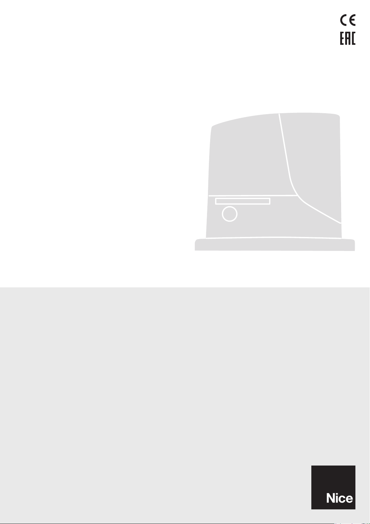
summing up all the severity indices specied in Table 2; the total result can then be compared with the estimated durability gures in the chart.
For example, ROBUS 1000 mounted on a 650 kg gate that is 5 m long, equipped with photocells and without other intensity-enhancing elements, corresponds to a severity index of 50% (30+10+10). An estimated durability of 80,000 cycles can be inferred from the chart.
English – 3
Page 6
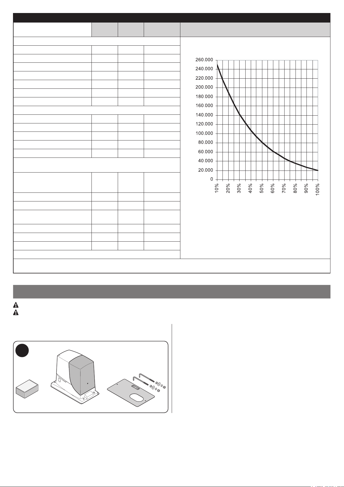
Table 2 - estimated durability in relation to the manoeuvre severity index
Severity index % RB600 RB1000 RB500HS
Gate leaf weight (kg)
Up to 200 10 5 30
200 – 400 30 10 40
400 – 500 50 20 60
500 – 600 - 30 -
600 – 800 - 40 -
800 – 900 - 50 -
900 – 1000 - 60 -
Gate leaf length (m)
Up to 4 10 5 15
4 – 6 20 10 25
6 – 8 35 20 35
8 – 10 - 35 -
10 – 12 - 50 -
Other factors contributing to fatigue
(to be considered if their probability exceeds 10%)
Ambient temperature greater
than 40°C or lower than 0°C, or
humidity greater than 80%
Presence of dust and sand 15 15 15
Presence of salinity 20 20 20
Manoeuvre interrupted by
photocell
Manoeuvre interrupted by Stop 25 20 30
Speed greater than “L4 fast” 20 15 25
Active peak force 25 20 25
Total severity index %:
Note: a severity index exceeding 100% implies that the conditions are beyond the limit of acceptability; in this case, a larger-size model is
recommended.
10 10 10
15 10 20
RB500HS/V1
Durability in cycles
Durability in cycles
Severity index %
INSTALLATION
3
Important! Before installing the product, refer to Chapter 2 and Chapter 12 (technical specications).
Vericare che la temperatura sia idonea all’ambito di applicazione.
Fig. 1 shows the contents of the package: check that everything is
present and correct.
1
Fig. 2 shows the location of the various components of a typical installation with Nice accessories:
a - ROBUS gearmotor
b - photocells
c - posts for photocells
d - key selector / digital keypad
e - ashing light
f - rack
4 – English
Page 7
D C BF AFE D
a
b
b
f
c
c
d
e
2
Before installing the system, check the gearmotor’s overall dimensions (Fig. 3) and installation measurements (Fig. 4):
3
330 mm
4
0 – 10 mm
192 mm
330 mm
01. Dig the foundation and arrange the tubes for the electrical
cables
0 – 50 mm
303 mm
212 mm
0 – 50 mm
92 mm
HS: 98 mm
0 – 10 mm
192 mm
330 mm
English – 5
Page 8
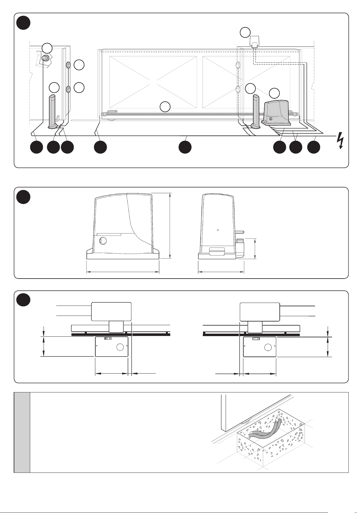
02. Secure the two anchor bolts to the foundation plate with
one nut above and one below the latter.
Tighten the lower nut in such a way that the upper
thread protrudes by roughly 25/35 mm.
03. Cast the concrete to secure the foundation plate.
Before the concrete hardens, make sure the
foundation plate is perfectly level and parallel to the
gate leaf.
04. Wait for the concrete to harden.
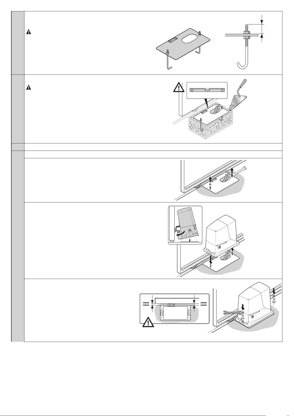
05. Secure the gearmotor:
a - remove the top nuts of the anchor bolts
25 – 35 mm
b - place the gearmotor on the anchor bolts: make sure
that it lies parallel with the gate leaf
c - insert the washers and nuts provided and tighten them
slightly
6 – English
Page 9
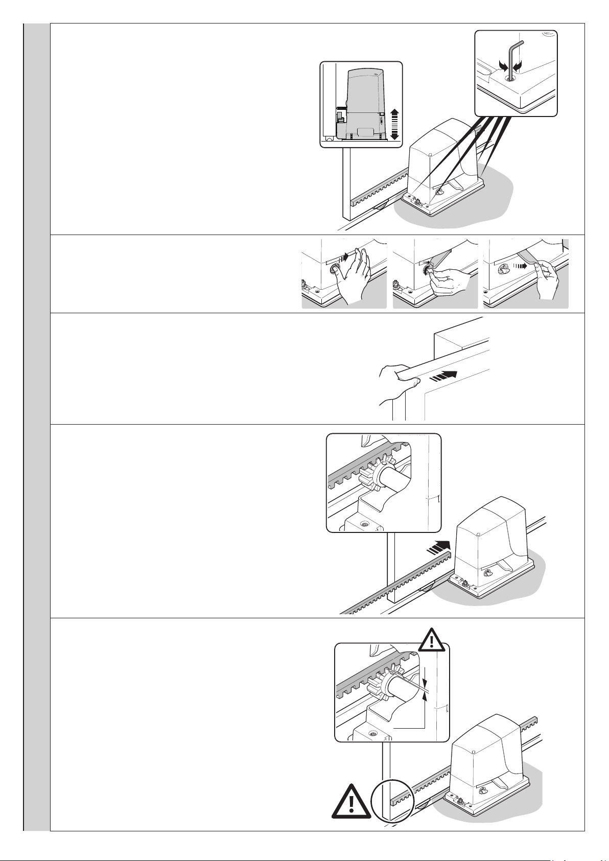
d - adjust the gearmotor’s height by tightening the adjust-
g
1÷2 mm
g
1÷2 mm
g
g
er grub screws: position the pinion at the right height by
leaving a gap of 1–2 mm from the rack (this so as to prevent the gate leaf weight from bearing on the gearmotor)
e / f / g - release the gearmotor
h - manually open the gate leaf fully
i - place the rst section of the rack on the gearmotor’s
pinion: make sure that it corresponds to the start of the
gate leaf and that there is a gap of 1–2 mm between the
rack and the pinion (this so as to prevent the gate leaf
weight from bearing on the gearmotor)
l - secure the rack section
1÷2 mm
English – 7
Page 10
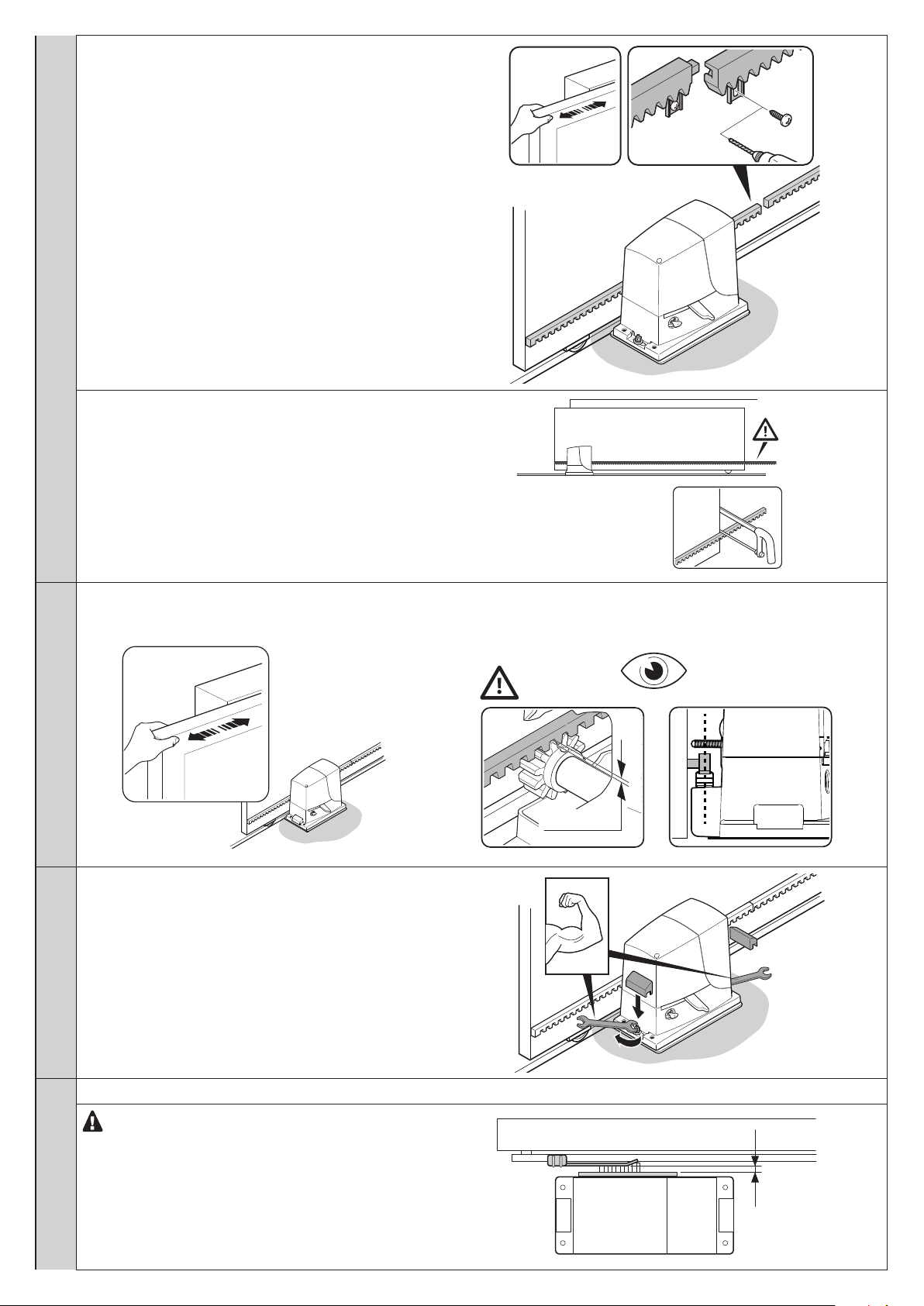
m - slide the gate by hand and, using the pinion as a refer-
1÷2 mm
g
h
1÷2 mm
g
ence, secure the other sections of the rack
n - cut any excess rack off the end
06. Slide the gate open and closed by hand to check that the rack is properly aligned with the pinion.
N.B.: make sure that there is a gap of 1–2 mm between the rack and pinion for the entire length of the gate
1÷2 mm
07. Strongly tighten the nuts for xing the gearmotor to the
foundation plate and cover the nuts with the relevant caps
08. Secure the OPEN and CLOSE limit switch bracket: perform the same operations for both limit switches
For the RB600P and RB1000P versions with induc-
tive proximity limit switch, the optimal distance of the
bracket is between 3 and 8 mm
8 – English
3–8 mm
Page 11
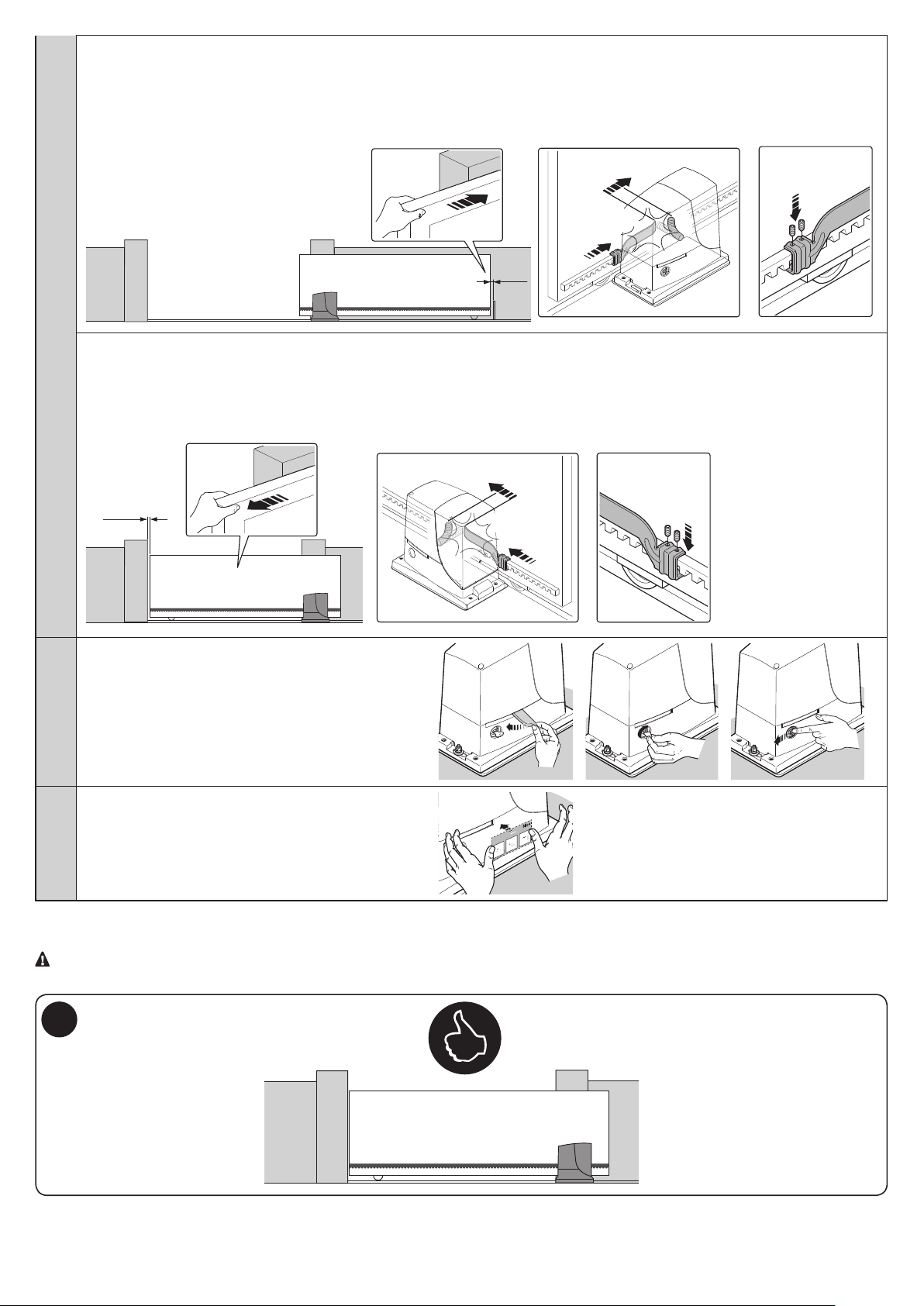
OPEN:
+2 cm
a - slide the gate leaf open by hand, stopping it 2/3 cm before the mechanical stop
b - slide the limit switch bracket along the rack in the open direction until the limit switch intervenes (a “click” will be heard)
c - after hearing the “click”, move the bracket further forward by 2 cm (minimum)
d - secure the bracket to the rack with the grub screws provided
+2 cm
click!
2-3 cm
CLOSE:
a - slide the gate leaf closed by hand, stopping it 2/3 cm before the mechanical stop
b - slide the limit switch bracket along the rack in the close direction until the limit switch intervenes (a “click” will be heard)
c - after hearing the “click”, move the bracket further forward by 2 cm (minimum)
d - secure the bracket to the rack with the grub screws provided
2-3 cm
click!
09. Manually lock the gearmotor
10. Apply the adhesive label showing the release instructions
Per Sbloccare - Pour débrayer - To unblock
Um zu entriegeln - Para desbloquear
Odblokowanie - Om te deblokkeren - Отпереть
1 2 3
To install the devices belonging to the system, refer to the respective instruction manuals.
IMPORTANT! – The gearmotor is congured (factory setting) for installation on the right-hand side (Fig. 5); to install it on the
left-hand side, perform the operations shown in Fig. 6.
5
English – 9
Page 12

6
ELECTRICAL CONNECTIONS
4
CAUTION! – All electrical connections must be made with the system disconnected from the power supply. Incorrect connec-
tions can cause damage to the equipment and injury to people.
CAUTION! – The cables used must be suited to the type of installation; for example a type-H03VV-F cable is recommended for
indoor environments, and a type-H07RN-F cable for outdoor environments.
Fig. 2 shows the electrical connections in a typical installation; Fig. 7 shows the connections to be made on the control unit.
4.1 - Types of electrical cables
Table 3 - Types of electrical cable (see Fig. 2)
Connection Type of cable Maximum length
A POWER SUPPLY 1 cable: 3 x 1.5 mm
B FLASHING LIGHT WITH AERIAL 1 cable: 2 x 0.5 mm
1 type-RG58 shielded cable
C PHOTOCELLS 1 cable: 2 x 0.25 mm
D KEY SELECTOR 2 cables: 2 x 0.5 mm
E FIXED EDGES 1 cable: 2 x 0.5 mm
F MOVABLE EDGES 1 cable: 2 x 0.5 mm
*
If the power supply cable is longer than 30 m, a cable with larger gauge is required, e.g. 3 x 2.5 mm
must be arranged near the automation.
**
***
****
*****
If the “BLUEBUS” cable is longer than 30 m, up to maximum 50 m, a 2 x 1 mm
The two 2 x 0.5 mm
2
cables can be replaced by a single 4 x 0.5 mm2 cable.
If more than one edge is present, refer to Paragraph 8.1 “STOP Input” for the type of connection recommended.
Special devices, which enable connection even when the leaf is moving, must be used to connect movable edges to sliding leaves.
2
2
2
2
*** 50 m
2
**** 30 m
2
**** 30 m *****
30 m *
20 m
20 m (recommended < 5 m)
30 m **
2
, and a safety earthing system
2
cable is required.
4.2 - Electrical cable connections: Fig. 7
Table 4 - Description of electrical connections
Function Description
FLASH
OGI - “Gate Open Indicator” output; a 24 V (max. 4 W) signal light can be connected. It can also be programmed for other
BLUEBUS - this terminal allows for connecting compatible devices; all are connected in parallel with just two wires conveying both
STOP - input for the devices that block or even stop the current manoeuvre; contacts like “Normally Closed”, “Normally Open”
Sbs - input for devices that control movement in Step-Step mode; it is possible to connect “Normally Open” contacts
OPEN - input for devices that control the opening movement only; it is possible to connect “Normally Open” contacts
CLOSE - input for devices that control the closing movement only; it is possible to connect “Normally Open” contacts
AUX_IN - input for devices that block or stop the manoeuvre in progress; Normally Closed (NC) contacts can be connected to
AERIAL - input for connecting the aerial for the radio receiver (the aerial is incorporated on LUCY B)
To make the electrical connections, proceed as described below and refer to Fig. 7:
- output for connecting a Nice ashing light (see models under “TECHNICAL SPECIFICATIONS” on page 28). During
the manoeuvre, the light ashes 0.5 seconds on and 0.5 seconds off
functions; refer to Paragraph 7.4 “Level 2 functions”
the power and the communication signals. Further information on the BLUEBUS appears in Paragraph 8.1 “BLUEBUS”
or constant resistance devices can be connected through special arrangements on the input
this input; using Oview, the input function can be changed; the input is factory congured to ALT
10 – English
Page 13

01. Open the cover: loosen the screw and raise the cover
02. Feed the power cable through the relevant hole (leave 20/30 cm of free cable) and connect it to the relevant terminal clamp
03. Feed the cables of the devices to be installed or already present in the system through the relevant hole (leave 20/30 cm of free cable)
and connect them to their terminal clamps as shown in Fig. 7
04. Before closing the cover, program the system: Chapter 7
05. Close the cover with the relevant screw
7
SELECTOR
KEYS
LED FUNCTION LEDS
RECEIVER RADIO RECEIVER SBS STEP BY STEP
AERIAL AERIAL OPEN OPEN
FUSE FUSE CLOSE CLOSE
FLASH FLASHING LIGHT AUX_IN AUXILIARY INPUT
DIRECTION
SELECTOR
PROGRAMMING AND
CONTROL KEYS
OGI GATE OPEN INDICATOR
TX - RX PHOTOCELLS
STOP
NO-NC-8K2
STOP
SENSITIVE EDGE
FLASH
OGI
24V 4W
OGI
Flash
Bluebus
Stop
1.6AT
TX
Bluebus Bluebus
Sbs
Open
Close
LED
Receiver
Aerial
RX
NC
AUX IN
Aux In
L1L2L3L4L5L6L7L8
OpenStop/SetClose
STOP
NO
NC
8K2
NO NO
CLOSE
OPEN
SBS
NO
KEYS
OFF
IBT4N
SELECTOR
L1L2L3L4L5L6L7L8
Open
Stop/Set
Close
English – 11
Page 14

STARTING THE AUTOMATION AND CHECKING THE CONNECTIONS
Per Sbloccare - Pour débrayer - To unblock
Um zu entriegeln - Para desbloquear
Odblokowanie - Om te deblokkeren - Отпереть
1 2 3
Per Sbloccare - Pour débrayer - To unblock
Um zu entriegeln - Para desbloquear
Odblokowanie - Om te deblokkeren - Отпереть
1 2 3
Per Sbloccare - Pour débrayer - To unblock
Um zu entriegeln - Para desbloquear
Odblokowanie - Om te deblokkeren - Отпереть
1 2 3
Per Sbloccare - Pour débrayer - To unblock
Um zu entriegeln - Para desbloquear
Odblokowanie - Om te deblokkeren - Отпереть
1 2 3
Per Sbloccare - Pour débrayer - To unblock
Um zu entriegeln - Para desbloquear
Odblokowanie - Om te deblokkeren - Отпереть
1 2 3
Per Sbloccare - Pour débrayer - To unblock
Um zu entriegeln - Para desbloquear
Odblokowanie - Om te deblokkeren - Отпереть
1 2 3
Per Sbloccare - Pour débrayer - To unblock
Um zu entriegeln - Para desbloquear
Odblokowanie - Om te deblokkeren - Отпереть
1 2 3
Per Sbloccare - Pour débrayer - To unblock
Um zu entriegeln - Para desbloquear
Odblokowanie - Om te deblokkeren - Отпереть
1 2 3
Per Sbloccare - Pour débrayer - To unblock
Um zu entriegeln - Para desbloquear
Odblokowanie - Om te deblokkeren - Отпереть
1 2 3
Per Sbloccare - Pour débrayer - To unblock
Um zu entriegeln - Para desbloquear
Odblokowanie - Om te deblokkeren - Отпереть
1 2 3
Per Sbloccare - Pour débrayer - To unblock
Um zu entriegeln - Para desbloquear
Odblokowanie - Om te deblokkeren - Отпереть
1 2 3
Per Sbloccare - Pour débrayer - To unblock
Um zu entriegeln - Para desbloquear
Odblokowanie - Om te deblokkeren - Отпереть
1 2 3
Aux In
L1L2L3L4L5L6L7
OpenStop/SetClose
5
5.1 - Connecting the automation to the mains electricity
CAUTION! – The automation must be connected to the mains electricity by an expert and qualied electrician, in accordance
with established laws, standards and local regulations.
Proceed as described below
01. Manually release the gearmotor so that the gate can be opened and closed
Per Sbloccare - Pour débrayer - To unblock
Um zu entriegeln - Para desbloquear
Odblokowanie - Om te deblokkeren - Отпереть
1 2 3
Per Sbloccare - Pour débrayer - To unblock
Um zu entriegeln - Para desbloquear
Odblokowanie - Om te deblokkeren - Отпереть
1 2 3
Per Sbloccare - Pour débrayer - To unblock
Um zu entriegeln - Para desbloquear
Odblokowanie - Om te deblokkeren - Отпереть
1 2 3
02. Move the gate leaf to the halfway position of its path
03. Manually lock the gearmotor
Per Sbloccare - Pour débrayer - To unblock
Um zu entriegeln - Para desbloquear
Odblokowanie - Om te deblokkeren - Отпереть
1 2 3
04. power the automation and verify:
- that the BLUEBUS LED ashes regularly at the frequency of one ash per second
Per Sbloccare - Pour débrayer - To unblock
Um zu entriegeln - Para desbloquear
Odblokowanie - Om te deblokkeren - Отпереть
1 2 3
Per Sbloccare - Pour débrayer - To unblock
Um zu entriegeln - Para desbloquear
Odblokowanie - Om te deblokkeren - Отпереть
1 2 3
- that the LEDs on the photocells ash (both on TX and RX); the type of ashing is not important as it depends on other factors
- that the ashing light connected to the FLASH output and the indicator light connected to the “Gate Open Indicator” output are ON
OFF
FLASH
TX RX
ON
OGI
OGI
Bluebus
Stop
Sbs
Open
Close
if any of these conditions are not satised, proceed as follows (step 05)
05. Shut off the mains power to the automation and check the electrical connections, photocell alignment and fuses
TESTING AND COMMISSIONING
6
These are the most important phases in the automation’s arrangement to ensure maximum system safety.
They must be carried out by a qualied and expert technician who must dene the necessary tests to verify the solutions adopted to counter
any risks present, and check compliance with laws, regulations, standards: in particular, all the requirements of the EN 13241-1, EN 12445 and
EN 12453 standards.
Any supplementary equipment must be tested separately for its operation and for correct interaction with ROBUS: refer to the respective user
manuals.
6.1 - Testing
The testing procedure can also be performed as a periodic check of the automation devices. Each component of the system (sensitive edges,
photocells, emergency stop, etc.) requires a specic testing phase; for these devices, observe the procedures given in the respective instruction
manuals.
12 – English
Page 15

Run the test as follows:
Per Sbloccare - Pour débrayer - To unblock
Um zu entriegeln - Para desbloquear
Odblokowanie - Om te deblokkeren - Отпереть
1 2 3
Per Sbloccare - Pour débrayer - To unblock
Um zu entriegeln - Para desbloquear
Odblokowanie - Om te deblokkeren - Отпереть
1 2 3
Per Sbloccare - Pour débrayer - To unblock
Um zu entriegeln - Para desbloquear
Odblokowanie - Om te deblokkeren - Отпереть
1 2 3
Per Sbloccare - Pour débrayer - To unblock
Um zu entriegeln - Para desbloquear
Odblokowanie - Om te deblokkeren - Отпереть
1 2 3
Per Sbloccare - Pour débrayer - To unblock
Um zu entriegeln - Para desbloquear
Odblokowanie - Om te deblokkeren - Отпереть
1 2 3
Per Sbloccare - Pour débrayer - To unblock
Um zu entriegeln - Para desbloquear
Odblokowanie - Om te deblokkeren - Отпереть
1 2 3
Per Sbloccare - Pour débrayer - To unblock
Um zu entriegeln - Para desbloquear
Odblokowanie - Om te deblokkeren - Отпереть
1 2 3
Per Sbloccare - Pour débrayer - To unblock
Um zu entriegeln - Para desbloquear
Odblokowanie - Om te deblokkeren - Отпереть
1 2 3
Per Sbloccare - Pour débrayer - To unblock
Um zu entriegeln - Para desbloquear
Odblokowanie - Om te deblokkeren - Отпереть
1 2 3
Per Sbloccare - Pour débrayer - To unblock
Um zu entriegeln - Para desbloquear
Odblokowanie - Om te deblokkeren - Отпереть
1 2 3
Per Sbloccare - Pour débrayer - To unblock
Um zu entriegeln - Para desbloquear
Odblokowanie - Om te deblokkeren - Отпереть
1 2 3
Per Sbloccare - Pour débrayer - To unblock
Um zu entriegeln - Para desbloquear
Odblokowanie - Om te deblokkeren - Отпереть
1 2 3
01. Ensure that all specications in the “WARNINGS” chapter have been strictly observed
02. Release the gearmotor and verify whether it is possible to manually move the gate in both directions (open and close) with a force no
greater than the value corresponding to the usage limits shown in Table 1
Per Sbloccare - Pour débrayer - To unblock
Um zu entriegeln - Para desbloquear
Odblokowanie - Om te deblokkeren - Отпереть
1 2 3
Per Sbloccare - Pour débrayer - To unblock
Um zu entriegeln - Para desbloquear
Odblokowanie - Om te deblokkeren - Отпереть
1 2 3
Per Sbloccare - Pour débrayer - To unblock
Um zu entriegeln - Para desbloquear
Odblokowanie - Om te deblokkeren - Отпереть
1 2 3
03. Lock the gearmotor
Per Sbloccare - Pour débrayer - To unblock
Um zu entriegeln - Para desbloquear
Odblokowanie - Om te deblokkeren - Отпереть
1 2 3
Per Sbloccare - Pour débrayer - To unblock
Um zu entriegeln - Para desbloquear
Odblokowanie - Om te deblokkeren - Отпереть
1 2 3
Per Sbloccare - Pour débrayer - To unblock
Um zu entriegeln - Para desbloquear
Odblokowanie - Om te deblokkeren - Отпереть
1 2 3
04. Using the key switch, control key or radio transmitter, test the opening and closing of the gate and make sure that it moves in the in-
tended direction
05. The test should be carried out several times to verify that the gate moves smoothly, that there are no points of excessive friction and
that there are no defects in the assembly or adjustment
06. Verify the correct operation of each safety device present in the system (photocells, sensitive edges, etc.)
07. Check the operation of the photocells and any interference with other devices:
1 - pass a cylinder with 5 cm diameter and 30 cm length along the optical axis, rst close to the TX then to the RX
2 - check that the photocells intervene in any condition, switching from active status to alarm status and vice-versa
3 - check that the photocell’s intervention determines the intended response of the control unit: for example, it causes the movement
to invert during the closing manoeuvre
4 - Whenever a device intervenes, the “BLUEBUS” LED on the control unit must ash 2 times more quickly, conrming that the control
unit recognises the event
08. If the dangerous situations caused by the gate’s movement have been safeguarded by limiting the impact force, the installer must
measure the impact force according to the EN 12453 standard
If the “Speed” adjustment and “Motor Force” control are used to assist the system in reducing the impact force, try to nd the adjustments that provide the best results
6.2 - Commissioning
Commissioning can only take place after all testing phases have been terminated successfully (Paragraph 6.1).
Partial or “makeshift” commissioning is strictly prohibited.
01. Prepare and store (for at least 10 years) the automation’s technical documentation. This must include at least: an assembly drawing
of the automation, a wiring diagram, analysis of risks and relative solutions adopted, manufacturer’s declaration of conformity for all
devices installed (for ROBUS use the annexed CE Declaration of Conformity); a copy of the automation system instruction manual and
maintenance schedule
02. Using the key selector or transmitter, test the opening and closing of the gate and make sure that it moves in the intended direction
03. Fill in the declaration of conformity of the automation and hand it to the owner
04. Hand over to the owner the “User Manual” (pull-out insert)
05. Prepare and hand to the owner the maintenance schedule of the automation
06. The force adjustment is an important safety factor and must be done with the utmost care by an qualied technicians. Important! -
Adjust the force sufciently to enable the gate to move as intended; higher force values to those necessary for moving the gate can
cause injury to animals and persons or damage to property if the gate collides with an obstacle
07. Before commissioning the gate, inform the owner adequately and in writing about the attendant residual risks
English – 13
Page 16

PROGRAMMING
ON
OFF
7
In this manual the programming procedures are explained with the use of icons and their meanings are given in the following glossary:
GLOSSARY
Symbol Description Symbol Description
LED on correct procedure
LED off INCORRECT procedure
short ashing LED
long ashing LED
very fast ashing LED
supply mains power press and hold key
shut off mains power
wait ...
Stop/Set
▲
▼
“OPEN” button = opening
“CLOSE” button = closure
“STOP” button = stop
“Set” button = used for programming
release key
press and release the key
7.1 - Programming
A number of programmable functions are available on the ROBUS control unit. The functions are adjusted using 3 keys on the
control unit: [▲], [Stop/Set], [▼] and are displayed through 8 LEDs: L1….L8.
Keys Function
▲
Stop/
Set
▼
The “OPEN” key enables the user to control opening of the gate or move the programming
point upwards
The “STOP/SET” button allows for stopping the manoeuvre. If pressed for more than 5
seconds, it allows for entering the programming mode
The “CLOSE” key enables the user to close the gate or move the programming point
downwards
7.2 - Level 1 functions (ON-OFF functions)
The programmable functions available on ROBUS are arranged on 2 levels:
Level 1: the functions can be adjusted in ON-OFF mode (active or not active); in this case, each LED L1….L8 indicates a function;
if on, the function is active and if off, the function is not active; see Table 5.
Table 5 - Programmable functions: Level 1
LED Function Description
L1 Automatic closing This function causes the gate to close automatically after the programmed pause time has
L2 Close after photo This function enables the gate to be kept open for the necessary transit time only. The
lapsed. The factory-set Pause Time is 30 seconds, but it can be modied to 5, 15, 30, 45,
60, 80, 120 or 180 seconds. If the function has not been activated, the “semi-automatic”
mode applies
“Photo” always causes an automatic re-closure with a pause time of 5 seconds (regardless
of the programmed value)
The behaviour changes depending on whether the “Automatic closing” function is active
or not
14 – English
Page 17

When “Automatic closing” is not active: the gate always reaches the fully open posi-
tion (even if the Photo disengages rst). The disengagement of Photo activates automatic
re-closure with a pause of 5 seconds
When “Automatic closing” is active: the opening manoeuvre stops immediately after the
photocells have disengaged. After 5 seconds, the gate will begin to re-close automatically.
The “Close after photo” function is always disabled in manoeuvres interrupted by a Stop
command
If the “Close after photo” function is inactive, the pause time is that which has been programmed or there will be no automatic re-closing if the function is inactive
L3 Always close The “Always close” function will intervene, and the gate will close, if the open gate status is
detected when the power supply returns. For safety reasons, the manoeuvre is preceded
by 5 seconds of ashing. If the function is not active when the power supply returns, the
gate will remain still
L4 Stand-by This function allows for minimising consumption and is particularly useful in cases when
the back-up battery is used. If this function is enabled, 1 minute after completion of the
manoeuvre the control unit turns off the BLUEBUS output (and therefore all devices) and all
LEDs, with the exception of the BLUEBUS LED, which ashes at a slower speed. When a
command arrives, the control unit will restore complete functioning. If this function is inactive, there will be no reduction in consumption
L5 Peak If this function is activated, the gradual acceleration at the beginning of each manoeuvre
will be disengaged; it allows for having peak thrust and is useful whenever static friction
is high, e.g. if snow or ice are blocking the gate. If the peak is inactive, the manoeuvre will
start with a gradual acceleration
L6 Pre-ashing With the pre-ashing function, a 3-second pause is added between the ashing light
switch-on and the start of the manoeuvre, in order to warn the user in advance of a poten-
tially dangerous situation. If pre-ashing is inactive, the ashing light will switch on when the
manoeuvre starts
L7 “Close” becomes “Partial open” Activating this function, the “CLOSE” input activates a partial opening manoeuvre (see LED
L6 in table 7)
L8 “Slave” mode With this option, ROBUS becomes a “Slave”: this allows for synchronising two motors on
opposing gate leaves, with one motor functioning as a Master and one as Slave; for further
information, see Paragraph 8.3 “ROBUS in “Slave” mode
During normal operation of ROBUS, LEDs L1….L8 are on/off in relation to the status of the respective function; for instance, L1 is on when
“Automatic closing” is active.
7.3 - Level 1 programming (ON-OFF functions)
By default, Level 1 functions are all set to “OFF”, but can be modied at any time as described in Table 6. Take care during modication procedures, as there is a maximum time interval of 10 seconds between pressing of different keys; otherwise the procedure
terminates automatically and stores the changes made up to that time.
Table 6 - Changing the ON-OFF Functions Example
01. Press and hold the [Stop/Set] key for roughly 3 seconds
02. Release the [Stop/Set] key when LED L1 starts ashing
03.
Press and release the [▲] or [▼] key to shift LED ashing on the desired “LED” (L1...L8 - Table 5)
Press and release the [Stop/Set] key to change the status of the function (short ashing = OFF; long
04.
ashing = ON)
05. Wait 10 seconds to exit the programming mode after the maximum time interval
N.B.: points 3 and 4 can be repeated during the same programming phase to set other functions to ON or OFF.
Open
Stop/Set
L1
or
Stop/Set
Stop/Set
Close
10s
3s
OFF
ON
English – 15
Page 18

7.4 - Level 2 Functions (adjustable parameters)
Level 2: the parameters can be adjusted on a scale of values (from 1 to 8); in this case, each of the LEDs L1….L8 indicates the
set value among 8 possible settings; refer to Table 7.
Table 7 - Programmable functions: Level 2
LED
Note: the parameters with a grey background are factory settings
L1 Pause Time L4
L2
L3 Motor speed
L4 OGI output
L5 Motor force
L6 Partial open
Parameter
Step-by-Step
function
Level Value Description
L1
L2
L3
L5
L6
L7
L8
L1 Open - Stop - Close - Stop
L2 Open - Stop - Close - Open
L3 Open - Close - Open - Close
L4 Apartment block
L5 Apartment block 2 (more than 2” gen-
L6 Step-by-Step 2 (less than 2” causes
L7 Hold-to-run
L8 “Semi-automatic” opening, “hold-to-
L1 Very slow
L2 Slow
L3 Medium
L4 Fast
L5 Very fast
L6 Extremely fast
L7 Opens “Fast”, Closes “Slow”
L8 Opens “Extremely fast”, Closes “Fast”
L1 “Gate Open Indicator” (G.O.I.) function
L2 On if gate closed
L3 On if gate open
L4 Active with radio output no. 2
L5 Active with radio output no. 3
L6 Active with radio output no. 4
L7 Maintenance indicator
L8 Electric lock
L1 Ultra-light gate
L2 Very light gate
L3 Light gate
L4 Average gate
L5 Medium-heavy gate
L6 Heavy gate
L7 Very heavy gate
L8 Ultra-heavy gate
L1 0.5 m
L2 1 m
L3 1.5 m
L4 2 m
L5 2.5 m
5 s
15 s
30 s
45 s
60 s
80 s
120 s
180 s
erates stop)
partial opening)
run” closing
Adjusts the pause time, that is, the time that
elapses before automatic re-closure. Is effective
only if automatic closure is enabled
Adjusts the sequence of commands associated
with the Step-by-Step input or the 1st radio command
Adjusts the motor speed during normal travel.
MODEL 500HS: factory setting = L5
Adjusts the function associated with OGI output
(whatever the associated function, the output
supplies a voltage of 24V
maximum power of 4 W when active)
Adjusts the system that controls the motor force
in order to adapt it to the weight of the gate. The
force control system also measures the ambient
temperature, automatically increasing the force in
the event of particularly low temperatures
Adjusts the measurement of the partial opening.
Partial opening can be controlled with the radio
command no. 2 or with “CLOSE”, if the “Close”
function is present, this becomes “Partial open”
(-30% +50%) with a
16 – English
Page 19

L6 3 m
Close
Close
L7 3.4 m
L8 4 m
L1 Automatic (depending on the severity
of the manoeuvre)
L2 1000
L3 2000
L7
Maintenance
notication
L4 4000
L5 7000
Controls the number of manoeuvres after which
the automation maintenance notication is sent
(see Paragraph 8.5 “Maintenance notication”)
L6 10000
L7 15000
L8 20000
st
manoeuvre (most recent)
nd
manoeuvre
rd
manoeuvre
th
manoeuvre
th
manoeuvre
th
manoeuvre
th
manoeuvre
Allows for verifying the type of fault occurring in
the last 8 manoeuvres (see Paragraph 9.1 “Fault
log list”)
L8
List of faults
L1
L2
L3
L4
L5
L6
L7
L8
Result of 1
Result of 2
Result of 3
Result of 4th manoeuvre
Result of 5
Result of 6
Result of 7
Result of 8
All the parameters can be adjusted as required without any contraindications; only the adjustment of the “Motor Force” could require special attention:
• Do not use high force values to compensate for points of abnormal friction on the leaf. Excessive force can compromise the operation of the
safety system or damage the leaf.
• If the “Motor Force” control is used to assist the impact force reduction system, measure the force again after each adjustment in compliance
with the EN 12453 standard.
• Wear and weather conditions may affect the movement of the gate, therefore periodic force readjustments may be necessary.
7.5 - Level 2 programming (adjustable parameters)
The adjustable parameters are factory set as shown in Table 7 with: “
” but can be modied at any time as shown in Table 8.
Take care during modication procedures, as there is a maximum time interval of 10 seconds between pressing of different keys;
otherwise the procedure terminates automatically and stores the changes made up to that time.
Table 8 - Changing the adjustable parameters Example
01. Press and hold the [Stop/Set] key for roughly 3 seconds
02. Release the [Stop/Set] key when LED L1 starts ashing
03.
Press and release the [▲] or [▼] key to shift LED ashing on the desired “LED” (L1...L8 - Table 7)
04. Press and hold the [Stop/Set] key, which must be kept pressed throughout all steps 5 and 6
Wait approx. 3 seconds after which the LED associated with the current level of the parameter to be
05.
modied will light up
06.
Press and release the [▲] or [▼] key to shift the LED that represents the value of the parameter
07. Release [Stop/Set]
Open
Open
Stop/Set
L1
or
or
Stop/Set
Stop/Set
Stop/Set
3s
08. Wait 10 seconds to exit the programming mode after the maximum time interval
N.B.: points 3 to 7 can be repeated during the same programming phase to modify other parameters.
10s
English – 17
Page 20

7.6 - Recognition of devices
After connecting up the power supply, the control unit must be made to recognise the devices connected up to the BLUEBUS and STOP inputs.
Before this phase, LEDs L1 and L2 will ash to indicate that recognition of the devices must be carried out.
01.
Press and hold [▲] and [Stop/Set]
02. Release the keys when LEDs L1 and L2 start to ash quickly (after roughly 3 seconds)
03. Wait a few seconds until the control unit has completed the device recognition pro-
cedure
04. Once the recognition stage has been completed, the STOP LED must remain on,
while LEDs L1 and L2 will switch off (LEDs L3 and L4 may start ashing)
The recognition phase of connected devices can be repeated at any time, even after installation (for example, if an additional device is installed);
to complete a new recognition procedure see Paragraph 8.4 “Recognition of other devices”.
7.7 - Recognition of the gate length
Once the devices have been recognised, LEDs L3 and L4 will start ashing; this means that the control unit must recognise the length of the
gate leaf (distance between the closing limit switch and the opening limit switch); this measurement is necessary to calculate the deceleration
points and the partial opening point.
01.
Press and hold [Stop/Set] and [▼]
02. Release the keys when the manoeuvre starts (after approx. 3 seconds)
03. Check that the current manoeuvre is an opening manoeuvre, otherwise press [Stop/
Set] and carefully check Chapter 3 (Figures 5 and 6); then repeat the sequence from
Point 1
04. Wait for the control unit to fully complete the gate opening manoeuvre until the opening limit switch; the closing manoeuvre will start immediately afterwards
05. Wait for the control unit to fully close the gate
Gate leaf length recognition mode 2 for model 500HS
This allows for conguring:
• “Deceleration” at the 10 cm mark during opening and closing;
• The “motor speed set-up” for opening and closing at 100% (ultra-fast mode, see Table 8).
This operating mode activates during the device recognition phase, by pressing and holding the [Stop/Set] and [▼] buttons for more than 8
seconds. After 8 seconds, LEDs L3 and L4 start ashing very quickly; at this point, release the [Stop/Set] and [▼] keys.
If the above conditions are not satised, immediately switch off the power supply to the control unit and carefully check the electrical connec-
tions.
7.8 - Checking gate movement
Upon completion of the gate length recognition, it is advisable to carry out a few manoeuvres in order to verify that the gate moves properly.
01.
Press the [▲] key to command an “Open” manoeuvre; check that gate opening occurs correctly, without any variations in speed; the
gate must only slow down and stop when it is between 70 and 50 cm from the opening limit switch, and stop as a result of the limit
switch at 2–3 cm from the mechanical opening stop
02.
Press the [▼] key to command a “Close” manoeuvre; check that gate opening occurs correctly, without any variations in speed; the
gate must only slow down and stop when it is between 70 and 50 cm from the closing limit switch, and stop as a result of the limit
switch at 2–3 cm from the mechanical closing stop
03. During the manoeuvre, check that the ashing light ashes at intervals of 0.5 seconds on and 0.5 seconds off. If present, also check the
ashes of the light connected to the OGI terminal: slow ashing during opening, quick ashing during closing.
04. Open and close the gate several times to make sure that there are no points of excessive friction and that there are no defects in the
assembly or adjustments
05. Check that the ROBUS gearmotor, rack and limit switch brackets are stably and safely secured, and are suitably resistant also during
sudden gate acceleration or deceleration movements
18 – English
Page 21

7.9 - Pre-set functions
The ROBUS control unit has several programmable functions. These functions are factory-set to a conguration that should satisfy most automations.
The functions can be modied at any time through an appropriate programming procedure; to this aim, refer to Paragraph 7.1 “Programming”.
7.10 - Radio receiver
To remote control ROBUS, an SM connector for SMXI or OXI type optional radio receivers is included on the control unit.
For further information consult the radio receiver instruction manual. To
insert the radio receiver, complete the operations indicated in the gure.
Table 9 describes the association between the radio receiver output
and the command that ROBUS will execute:
FURTHER INFORMATION
8
Output Command
N° 1 Sbs (Step-by-Step)
N° 2 Partial open
N° 3 Open
N° 4 Close
Table 9
8.1 - Adding or removing devices
Devices can be added to or removed from the ROBUS automation at any time. In particular, various types of devices can be connected to
“BLUEBUS” and “STOP” input as explained in the following paragraphs.
After adding or removing devices, it is necessary to rerun the device recognition procedure as described in Paragraph 8.4 “Recognition of other
devices”.
Bluebus
BLUEBUS is a technique that allows for connecting compatible devices using only two wires that carry both the power supply and the communication signals. All the devices are connected in parallel on the same 2 wires of the BLUEBUS, and without having to observe any polarity; each device is individually recognised because a univocal address is assigned to it during installation. Photocells, safety devices, control
keys, signalling lights etc. can be connected to BLUEBUS. The ROBUS control unit recognises all the connected devices individually through
a suitable recognition process, and can detect all possible anomalies with absolute precision. For this reason, each time a device connected
to BLUEBUS is added or removed, the control unit must go through the recognition procedure as described in Paragraph 8.4 “Recognition
of other devices”.
STOP input
STOP is the input that causes the immediate interruption of the manoeuvre (with a short reverse run). Devices with output featuring normally
open “NO” contacts and devices with normally closed “NC” contacts, as well as devices with 8.2 kΩ constant resistance output, such as
sensitive edges, can be connected to this input.
Similarly to BLUEBUS, the control unit recognises the type of device connected to the STOP input during the recognition phase (see Paragraph 8.4 “Recognition of other devices”); subsequently, a stop is triggered when any variation occurs with respect to the recognised status.
Multiple devices, even of different types, can be connected to the STOP input if suitable arrangements are made:
• Multiple NO devices can be connected to each other in parallel without any quantity limit.
• Multiple NC devices can be connected to each other in series without any quantity limit.
• Two devices with 8.2 kΩ constant resistance output can be connected in parallel; if there are more than 2 devices, all must be connected in
cascade, with a single 8.2 kΩ termination resistor.
• NO and NC combinations are possible by placing the 2 contacts in parallel, taking care to place a 8.2 kΩ resistor in series with the NC con-
tact (this allows for combining 3 devices: NO, NC and 8.2 kΩ).
If the STOP input is used to connect devices with safety functions, only the devices with 8.2 kΩ constant resistance guarantee Category 3
safety against faults in accordance with the EN 954-1 standard.
English – 19
Page 22

Photocells
Through addressing using special jumpers, the “BLUEBUS” system enables the control unit to recognise the photocells and assign the correct
detection function. The addressing operation must be done both on TX and RX (setting the jumpers in the same way), while making sure there
are no other pairs of photocells with the same address.
In an automation mechanism for sliding gates with ROBUS, it is possible to install photocells as shown in the gure.
Each time a photocell is added or removed, the control unit must go through the recognition process as described in Paragraph 8.4 “Recognition of other devices”.
Table 10
Photocells Jumpers
PHOTO
PHOTO II
PHOTO 1
PHOTO 1 II
PHOTO 2
PHOTO 2 II
PHOTO 3 Single photocell covering the entire automation
The joint installation of PHOTO 3 and PHOTO II requires that the position of the elements constituting the photocell (TX - RX) complies with
the precaution contained in the photocell instruction manual.
Photocell h = 50
with activation on closing
Photocell h = 100
with activation on closing
Photocell h = 50
with activation on closing
Photocell h = 100
with activation on closing
External photocell activated
when gate opens
Internal photocell activated
when gate opens
8.2 - FT210B Photosensor
The FT210B photosensor unites in a single device a force limiting device (type C in accordance with the EN12453 standard) and a presence
detector which detects the presence of obstacles on an optical axis between the TX transmitter and the RX receiver (type D in accordance with
the EN12453 standard). The sensitive edge status signals on the FT210B photosensor are transmitted by means of the photocell beam, integrating the two systems in a single device. The transmitting part is positioned on the mobile leaf and is powered by a battery, thereby eliminating
unsightly connection systems; battery consumption is reduced by special circuits to guarantee a duration of up to 15 years (see the estimation
details in the product instructions).
Combining a FT210B device with a sensitive edge (TCB65, for example) allows for attaining the level of security of the “main edge” required by
the EN12453 standard for all “types of use” and “types of activation”.
Photosensor FT210B combined with “resistive” sensitive edges (8.2 kΩ) is safe against single faults. It is equipped with a special anti-collision
circuit to prevent interference with other detectors, even not synchronised, and allows for adding other photocells; for example, in case of transit
of heavy vehicles where a second photocell is normally positioned at 1 m from the ground.
See the FT210B instruction manual for further information concerning connection and addressing methods.
20 – English
Page 23

8.3 - ROBUS in “Slave” mode
When properly programmed and connected, ROBUS can function in “Slave” mode; this type of function is used when 2 opposing gate leaves
must be automated with the synchronised movement of the two gate leaves. In this mode, one ROBUS functions as a Master commanding
the movement, while the second ROBUS functions as a Slave, by executing the commands transmitted by the Master (all ROBUS devices are
factory-set to operate as Masters).
To congure ROBUS as Slave, one “Slave Mode” Level 1 function must be activated (see Table 5).
01. The connection between ROBUS Master and ROBUS Slave
is made via BLUEBUS.
In this case the polarity of the connections between the
two ROBUS devices must be respected, as illustrated in the
gure (the other devices continue not having polarity)
Follow the operations below to install 2 ROBUS devices in
Master and Slave mode:
- Install the 2 motors
It is not important which motor must function as Slave or Master; the choice must take into account the convenience of the connections
and the fact that the Step-by-Step command of the Slave only allows the Slave leaf to be opened fully
- Connect the 2 motors
- Select the direction of the opening manoeuvre of the 2 motors (Figures 5-6)
- Power the 2 motors
- Programme the “Slave Mode” function on the Slave ROBUS (see Table 5)
- Run the device recognition on the Slave ROBUS (see Paragraph 7.6 “Recognition of devices”)
- Run the device recognition on the Master ROBUS (see Paragraph 7.6 “Recognition of devices”)
- Run the gate leaf length recognition on the Master ROBUS (see Paragraph 7.7 “Gate leaf length recognition”)
FLASH
Bluebus
SLAVE
Bluebus
FLASH
OGI
24V 4W
Flash
OGI
OGI
24V 4W
Flash
OGI
Stop
Bluebus
1.6AT
TX
Bluebus Bluebus
Sbs
Open
Close
LED
Receiver
Aerial
IBT4N
RX
NC
AUX IN
Aux In
L1L2L3L4L5L6L7L8
OpenStop/SetClose
KEYS
SELECTOR
MASTER Board SLAVE Board
STOP
NO
NC
8K2
NO NO
CLOSE
Bluebus
MASTER
SBS
NO
OPEN
2121
Bluebus
Bluebus
STOP
Sbs
Stop
1.6AT
IBT4N
LED
Receiver
Open
NO
NC
8K2
Close
Aerial
SBS
NO
Aux In
L1L2L3L4L5L6L7L8
OpenStop/SetClose
KEYS
SELECTOR
When connecting 2 ROBUS devices in Master-Slave mode, make sure that:
- All devices must be connected to the Master ROBUS, including the radio receiver.
- When using back-up batteries, each motor must have its own battery.
- All programming activities performed on the Slave ROBUS are ignored (those on Master ROBUS override the others)
except for those mentioned in Table 11.
English – 21
Page 24

Table 11 - Programming on Slave ROBUS independently from the Master ROBUS
Open
Open
Level 1 functions (ON-OFF functions) Level 2 functions (adjustable parameters)
Stand-by Motor speed
Peak OGI output
Slave mode Motor force
Error list
On Slave it is possible to connect:
• a ashing light (Flash)
• a Gate Open Indicator (OGI)
• a sensitive edge (Stop)
• a command device (Step-by-Step) that controls the full opening of the Slave gate leaf only
On the Slave, the Open, Close and Aux_In inputs are not used.
8.4 - Recognition of other devices
Normally the recognition of devices connected to the BLUEBUS and to the STOP input occurs during the installation phase. However, if new
devices are added or old ones removed, the recognition process completed again by proceeding as shown in Table 12.
Table 12 - Recognition of other devices Example
01.
Press and hold [▲] and [Stop/Set]
and
Stop/Set
02. Release the keys when LEDs L1 and L2 start to ash quickly (after roughly 3 seconds)
03. Wait a few seconds until the control unit has completed the device recognition procedure
At the end of the recognition process, LEDs L1 and L2 will stop ashing, the STOP LED must stay
04.
on, while LEDs L1...L8 will switch on based on the status of the ON-OFF functions they represent
After having added or removed a device, the automation must be tested again as specied in Paragraph “6.1 Testing”.
8.5 - Connecting the Oview programmer
The Oview programming unit can be connected to the control unit via
the IBT4N interface using a BUS cable with 4 electrical wires inside.
This unit allows the functions to be programmed quickly and compre-
hensively, the parameters to be adjusted, the control unit rmware to
be updated, and the diagnostics to be run to detect any malfunctions
and routine maintenance.
The Oview unit allows the control unit to be used at a distance of
approximately 100 m. If there are multiple control units connected together in a ‘BusT4’ network, by connecting the Oview to one of these
control units, all of the control units connected in the network can be
viewed on the display (maximum of 16 control units).
The Oview unit can remain connected to the control unit during normal
operation of the operator, allowing the user to send commands via a
specic menu.
WARNING! – Before connecting the IBT4N interface, discon-
nect the control unit from the mains electrical power supply.
2
1
Stop/Set
L1
L1
L2
L2
8.6 - Special functions
“Always open” function
The “Always open” function is a control unit feature that enables the user to control an opening manoeuvre when the “Step-by-Step” command lasts longer than 2 seconds. This is useful for connecting a timer contact to the “Step-by-Step” terminal in order to keep the gate open
for a certain amount of time, for example. This feature is valid regardless of the “Step-by-Step” input programming, except for “Close” – refer
to the “Step-by-Step Function” parameter in Table 7.
If the STOP input is used to connect devices with safety functions, only devices with 8.2 kΩ constant resistance output guarantee ade-
quate safety against faults.
22 – English
Page 25

“Move anyway” function
Close
Close
Stop/Set
Stop/Set
Open
In the event that one of the safety devices is not functioning properly or is out of order, it is still possible to command and move the gate in
“Man present” mode.
Please refer to the paragraph “Control with safety devices out of order” in the annex “User manual” for further information.
Maintenance notication
ROBUS allows for notifying the user when the automation requires a maintenance control. The number of manoeuvres after the notication
can be selected from among 8 levels, by means of the “Maintenance notication” adjustable parameter (see Table 7).
Adjustment level 1 is “automatic” and takes into consideration the severity of the manoeuvre, this being the force and duration of the manoeu-
vre, while the other adjustments are dened based on the number of manoeuvres.
The maintenance request notication is given by means of the “Flash” ashing light or through the lamp connected to the OGI output when
programmed as a “Maintenance indicator” (see Table 7).
The “Flash” ashing light and the maintenance indicator give the signals indicated in Table 13 based on the number of manoeuvres performed
with respect to the programmed limits.
Table 13- Maintenance notice signals
Number of manoeuvres Signal on “Flash” Signal on maintenance indicator
Lower than 80% of the limit Normal (0.5 s on, 0.5 s off) On for 2 s at the start of opening
Between 81% and 100% of the
limit
Over 100% of the limit
At the start of the manoeuvre, it remains lit for 2 s then
continues normally
At the start and end of the manoeuvre, remains lit for 2 s
then continues normally
Flashes throughout the manoeuvre
Flashes always
Check of the number of manoeuvres performed
The number of manoeuvres performed as a percentage of the set limit can be veried by means of the “Maintenance notication” function. For
the check proceed as described in Table 14.
Table 14 - Check of the number of manoeuvres performed Example
01. Press and hold the [Stop/Set] key for roughly 3 seconds
02. Release the [Stop/Set] key when LED L1 starts ashing
Press and release the [▲] or [▼] keys to shift LED ashing on L7, namely the “input LED”
03.
associated with the “Maintenance notication” parameter
04. Press and hold the [Stop/Set] key, which must be kept pressed throughout all steps 5, 6 and 7
Wait approx. 3 seconds after which the LED associated with the current level of the “Maintenance
05.
notication” parameter will light up
06.
Press and release [▲] and [▼]
The LED corresponding to the selected level ashes a few times. The number of ashes indicates
the percentage of manoeuvres performed (in multiples of 10%) with respect to the set limit.
For example: with the maintenance notication set to L6 namely 10000, 10% corresponds to 1000
07.
manoeuvres; if the visualisation LED ashes 4 times, it means that 40% of the manoeuvres has
been reached (being between 4000 and 4999 manoeuvres). If 10% of the manoeuvres has not yet
been reached, the LED does not ash at all
Open
Stop/Set
L1
or
Open
...
Stop/Set
and
Stop/Set
3s
3s
n=?
L7
08. Release [Stop/Set]
Manoeuvre counter resetting
After maintenance has been performed on the system, the manoeuvre counter must be reset.
Proceed as described in Table 15.
Table 15 - Manoeuvre counter resetting Example
01. Press and hold the [Stop/Set] key for roughly 3 seconds
02. Release the [Stop/Set] key when LED L1 starts ashing
Press and release the [▲] or [▼] keys to shift LED ashing on L7, namely the “input LED”
03.
associated with the “Maintenance notication” parameter
L1
or
Stop/Set
3s
L7
English – 23
Page 26

04. Press and hold the [Stop/Set] key, which must be kept pressed throughout all steps 5, 6 and 7
Wait approx. 3 seconds after which the LED associated with the current level of the “Maintenance
05.
notication” parameter will light up
Press and hold buttons [▲] and [▼] for at least 5 seconds, then release the 2 buttons.
06.
The LED that corresponds to the selected level ashes rapidly indicating that the manoeuvre
counter has been reset
and
3s
5s
07. Release [Stop/Set]
8.7 - Connecting other devices
If the user needs to power external devices, such as a proximity reader for transponder cards or the illumination
light of the key-operated selector switch, it is possible to tap power as shown in the gure.
The power supply voltage is 24V
(-30% +50%) with a maximum available current of 100 mA.
𝌂
8.8 - Accessories
The following optional accessories are available for ROBUS:
• SMXI or OXI Radio receiver at 433.92 MHz with Rolling Code digital coding
• PS124 24 V - 1.2 Ah back-up battery with integrated battery charger
• SOLEMYO solar power system (for installation and connection refer to the product’s instruction manual)
SMXI o OXI
PS124
STOP
GND (-)
SBS
24V (+)
DIAGNOSTICS
9
In case of malfunction due to problems during installation or a fault, refer to Table 16:
Table 16
Problem Solution
The radio transmitter does not control the
gate and the LED on the transmitter does
not light up
The radio transmitter does not control the
gate but the LED on the transmitter lights up
No manoeuvre starts and the “BLUEBUS”
LED does not ash
No manoeuvre starts and the ashing light
is off
24 – English
Check whether the transmitter batteries are exhausted and replace them if necessary
Check whether the transmitter has been memorised correctly in the radio receiver
Check that ROBUS is powered with the mains voltage
Check that the fuses are not blown; if they are, identify the reason for the failure and replace
them with others having the same current rating and characteristics
Check that the command is actually received. If the command reaches the Step-by-Step input,
the corresponding “Step-by-Step” LED must light up; if instead the radio transmitter is used,
the “BlueBus” LED must make two quick ashes
Check that the command is actually received. If the command reaches the Step-by-Step input,
the corresponding “Step-by-Step” LED must light up; if instead the radio transmitter is used,
the “BlueBus” LED must make two quick ashes
Page 27

No manoeuvre starts and the ashing light
Close
Open
Close
Count the ashes and check the corresponding value in Table 18
ashes a few times
The manoeuvre starts but is immediately followed by a reverse run
The manoeuvre is carried out but the ashing
light does not work
The selected force could be too low for this type of gate. Check whether there are any obstacles and increase the force if necessary
Make sure that there is voltage on the ashing light’s FLASH terminal during the manoeuvre
(being intermittent, the voltage value is not important: approximately 10-30 VDC); if there is
voltage, the problem is due to the lamp; in this case replace the lamp with one having the same
characteristics; if there is no voltage, there may have been an overload on the FLASH output.
Check that the cable has not short-circuited
The manoeuvre is carried out but the Gate
Open Indicator (OGI) does not work
Check the type of function programmed for the OGI output (Table 7)
When the indicator light should be on, check that there is voltage on the OGI terminal (approximately 24V). If there is voltage, the problem is due to the indicator light, which will have to be
replaced with one having the same characteristics. If there is no voltage, there may have been
an overload on the OGI output. Check that the cable has not short-circuited
9.1 - Fault log list
ROBUS can display any faults that have occurred in the last 8 manoeuvres, for example interruption of a manoeuvre due to activation of a photocell or sensitive edge. To check the list of faults proceed as shown in Table 17.
Table 17 - Fault log Example
01. Press and hold the [Stop/Set] key for roughly 3 seconds
02. Release the [Stop/Set] key when LED L1 starts ashing
Press and release the [▲] or [▼] keys to shift LED ashing on L8, namely the “input LED”
03.
associated with the “Fault log” parameter
Open
Stop/Set
L1
or
Stop/Set
3s
L8
04. Press and hold the [Stop/Set] key, which must be kept pressed throughout all steps 5 and 6
Wait approx. 3 seconds after which the LEDs corresponding to the faulty manoeuvres will light
up. LED L1 indicates the result of the last manoeuvre and LED L8 indicates the result of the 8th
05.
manoeuvre. If the LED is on, this means that faults occurred during the manoeuvre; if the LED is off,
3s
this means that no fault occurred during the manoeuvre
Press and release the [▲] and [▼] keys to select the desired manoeuvre:
06.
The corresponding LED emits a number of ashes equal to those normally emitted by the ashing
light after a fault (see Table 18)
07. Release [Stop/Set]
Open
and
Stop/Set
9.2 - Diagnostics and signals
Certain devices directly provide special signals that help to describe the operating status or any malfunction.
9.2.1 - Flashing light signals
During the manoeuvre the FLASH ashing light ashes once every second. When a fault occurs, the ashes become more frequent; the light
ashes twice with a one-second pause between ashes.
Signal Cause Solution
1 ash
Bluebus system error At the start of the manoeuvre, the devices connected to BLUEBUS do not correspond
1-sec pause
1 ash
2 ashes
Intervention of a photocell At the start of the manoeuvre, one or more photocells prevent movement; verify
1-sec pause
2 ashes
3 ashes
1-sec pause
Activation of the “Motor Force”
limiting device
3 ashes
4 ashes
Intervention of the STOP input At the start of the manoeuvre or during the movement, the STOP input intervened;
1-sec pause
4 ashes
Table 18
to those memorised during the recognition phase. One or more devices may be faulty;
check and, if necessary, replace them; in case of modications the recognition process must be repeated
whether there are any obstacles.
This is normal when there is an obstacle hampering the gate’s movement
During the movement, the gate experienced excessive friction; identify the cause
identify the cause
English – 25
Page 28

5 ashes
1-sec pause
Error in the internal parameters of
the control unit
Wait at least 30 seconds then try giving a command; if the condition persists it means
there is a serious malfunction and the electronic board must be replaced
5 ashes
6 ashes
1-sec pause
The maximum manoeuvre limit/
hour has been exceeded
Wait a few minutes until the manoeuvre limiting device drops below the maximum limit
6 ashes
7 ashes
1-sec pause
7 ashes
8 ashes
1-sec pause
8 ashes
9 ashes
1 second pause
Error in the internal electric
circuits
A command that does not allow
other commands to be executed
is already present
The operator has been blocked
by a “block operator” command
Disconnect all power circuits for a few seconds then try to give a command again. If
the condition persists it means there is a serious malfunction and the electronic board
must be replaced
Check the type of command that is always present; for example, it could be a command from a timer on the “open” input
Release the operator by sending a “release operator” command.
9 ashes
9.2.2 - Control unit signals
The ROBUS unit has a series of LEDs, each of which can emit special
signals both during regular operation and when a fault occurs.
Flash
OGI
Bluebus
Stop
1.6AT
Sbs
Open
Close
Aux In
L1L2L3L4L5L6L7L8
OpenStop/SetClose
Table 19 - LED’s on the control unit’s terminals
BLUEBUS LED Cause Action
Off Fault Make sure there is power supply; check to see if the fuses are blown; if nec-
On Serious fault There is a serious fault; try switching off the control unit for a few seconds; if
1 ash per second All OK Control unit works correctly
2 quick ashes Input status variation This is normal when there is a change in one of the inputs: OPEN, STOP, trig-
Series of ashes sepa-
Various This is the same signal that appears on the ashing light. See Table 18
rated by a one-second
pause
STOP LED Cause Action
Off Intervention of the STOP input Check the devices connected to the STOP input
On All OK STOP input active
Sbs LED Cause Action
Off All OK Sbs input not active
On Intervention of the Sbs input Normal if the device connected to the Sbs input is active
OPEN LED Cause Action
Off All OK OPEN input not active
On Intervention of the OPEN input Normal if the device connected to the OPEN input is active
CLOSE LED Cause Action
Off All OK CLOSE input not active
On Intervention of the CLOSE input Normal if the device connected to the CLOSE input is active
AUX_IN LED Causa Azione
Off AUX_IN input contact open Check the devices connected to the AUX_IN input
On All OK AUX_IN input active
essary, identify the reason for the failure then replace them with others of the
same type
the condition persists, it means there is a malfunction and the circuit board
has to be replaced
gering of photocells or the radio transmitter is used
26 – English
Page 29

Table 20 - LED’s on the control unit keys
L1 LED Description
Off During normal operation it signals that the “Automatic closing” mode is not active
On During normal operation it signals that the “Automatic closing” mode is active
Flashes • Function programming in progress
L2 LED Description
Off During normal operation it signals that the “Close after photo” mode is not active
On During normal operation it signals that the “Close after photo” mode is active
Flashes • Function programming in progress
L3 LED Description
Off During normal operation it signals that the “Always close” mode is not active
On During normal operation it signals that the “Always close” mode is active
Flashes • Function programming in progress
LED L4 Description
Off During normal operation it signals that the “Standby” mode is not active
On During normal operation it signals that the “Standby” mode is active
Flashes • Function programming in progress
LED L5 Description
Off During normal operation it indicates that the “Peak” mode is not active
On During normal operation it signals that the “Thrust” mode is active
Flashes Function programming in progress
LED L6 Description
Off During normal operation it signals that the “Pre-ashing” mode is not active
On During normal operation it signals that the “Pre-ashing” mode is active
Flashes Function programming in progress
LED L7 Description
Off During normal operation it signals that the “CLOSE” input activates a closing manoeuvre
On During normal operation it signals that the “CLOSE” input activates a partial opening manoeuvre
Flashes Function programming in progress
LED L8 Description
Off During normal operation it signals that ROBUS is congured as Master
On During normal operation it signals that ROBUS is congured as Slave
Flashes Function programming in progress
• If it ashes together with L2, it means that the device recognition phase must be carried out (Paragraph 7.6)
• If it ashes together with L1, it means that the device recognition phase must be carried out (Paragraph 7.6)
• If it ashes together with LED L4, the gate leaf length recognition phase must be carried out (Paragraph 7.7)
• If it ashes together with LED L3, the gate leaf length recognition phase must be carried out (Paragraph 7.7)
10
This product constitutes an integral part of the automation and, therefore, must be disposed of together with it.
Similarly to the installation phase, once the product reaches the end of its useful life, the disassembly and scrapping operations must be per-
formed by qualied personnel.
This product is made of various types of materials, some of which can be recycled while others must be scrapped. Seek information on the
recycling and disposal systems envisaged by local regulations in your area for this product category.
constitute serious environmental and health risks.
PRODUCT DISPOSAL
CAUTION! - Some parts of the product may contain polluting or hazardous substances which, if released into the environment,
As indicated by the adjacent symbol, the product may not be disposed of together with domestic waste. Sort the materials for
disposal, according to the methods envisaged by current legislation in your area, or return the product to the retailer when purchasing an equivalent product.
CAUTION! - Local legislation may include the application of heavy nes in the event of improper disposal of this
product.
English – 27
Page 30

11
OFF
ON
To ensure constant safety levels a long service life, the system must be serviced regularly: at least every 6 months or after maximum 20,000
movements since the last service. ROBUS is equipped with a manoeuvre counter and a maintenance notication system; see Paragraph 8.5
“Maintenance notication”.
manual and according to applicable legislation and standards.
MAINTENANCE
CAUTION! – The maintenance operations must be performed in strict compliance with the safety directions provided in this
01.
Check the state of deterioration of all materials constituting the automation: pay special attention to erosion and oxidation of
structural components. Replace any parts that are not to standard
02. Check the state of wear of moving parts: pinion, rack and all parts of the gate leaf; replace any worn components if necessary
03.
12
All technical specications stated herein refer to an ambient temperature of 20°C (± 5°C). • Nice S.p.A. reserves the right to modify its prod-
ucts at any time when deemed necessary, while nonetheless maintaining their intended use and functionality.
Product type Electromechanical gearmotor for the automatic movement of sliding gates for residential use, inclusive of
Pinion Z15m4 Z15m4 Z18m4 Z18m4
Maximum frequency of operating
cycles (at nominal torque)
Maximum continuous operating
time (at nominal torque)
Application limits ROBUS is generally able to automate gates up to the weight and length limits specied in Table 1
Durability Estimated between 20,000 and 250,000 cycles, depending on the conditions given in Table 2
Power supply
Version V1
Maximum power input at peak
[corresponding to amperes]
Insulation class 1 (a safety earthing system is required)
Emergency power supply With PS124 optional accessory
Flashing light output For 2 ashing ELDC LED lights or max. 2 x 12V 21W bulbs
Gate Open Indicator (OGI) output For one 24 V maximum 4 W lamp (the output voltage may vary between –30 and +50% and can also
BLUEBUS output One output with maximum load of 15 BLUEBUS units
STOP input For normally closed or normally open contacts or for 8.2 kΩ constant resistance with self-recognition
Step-by-step input For normally open contacts (contact closure triggers a step-by-step command)
OPEN input For normally open contacts (closing of the contact triggers the OPEN command)
CLOSE input For normally open contacts (closing of the contact triggers the CLOSE command)
AUX_IN input For normally closed contacts (contact opening triggers an ALT command)
Radio connector SM connector for SMXI and OXI receivers
Radio ANTENNA Input 52 Ω for RG58 or similar type cable
Programmable functions 8 ON-OFF functions and 8 adjustable functions (see Tables 5 and 7)
Self-recognition functions Automatic recognition of devices connected to the BLUEBUS output
28 – English
Run all the tests and checks indicated in Paragraph 6.1 - Testing
TECHNICAL SPECIFICATIONS
RB600 / RB600P RB1000 / RB1000P RB500HS RB500HS/V1
electronic control unit
100 cycles / day
(the control unit limits
the cycles to the maximum value specied in
Table 2)
7 minutes
(the control unit limits
continuous operation
to the maximum value
specied in Table 2)
230V~ (+10% -15%)
50/60Hz
120V~ 50/60Hz
515W [2,5A]
[4,8A versione /V1]
control small relays)
(any variation from the memorised status triggers the “STOP” command)
Self-recognition of the type of “STOP” device (Normally Open, Normally Closed contact or 8.2 kΩ resistor)
Self-recognition of the gate length and calculation of the deceleration points and partial opening points
150 cycles / day
(the control unit limits
the cycles to the maximum value specied in
Table 2)
5 minutes
(the control unit limits
continuous operation
to the maximum value
specied in Table 2)
230V~ (+10% -15%)
50/60Hz
120V~ 50/60Hz
450W [2,3A]
[4,4A versione /V1]
100 cycles / day
(the control unit
limits the cycles to
the maximum value
specied in Table 2)
6 minutes
(the control unit limits
continuous operation
to the maximum value
specied in Table 2)
230V
(+10% -15%)
50/60Hz
460W [2,5A] 460W [4,8A]
100 cycles / day
(the control unit limits the cy-
cles to the maximum value
specied in Table 2)
6 minutes
(the control unit limits
continuous operation to the
maximum value specied in
Table 2)
120V
50/60 Hz
Page 31

EU Declaration of Conformity
and declaration of incorporation of “partly completed machinery”
Note: the contents of this declaration correspond to that stated in the ofcial document led in the ofces of Nice S.p.A. and, in particular,
the latest version thereof available prior to the printing of this manual. The text herein has been re-edited for editorial purposes. A copy of
the original declaration can be requested from Nice S.p.A. (TV) Italy.
Declaration number: 210/ROBUS Revision: 16 Language: EN
Manufacturer’s name: NICE S.p.A.
Address: Via Callalta n°1, 31046 Rustignè di Oderzo (TV) Italy
Person authorised to compile the technical documentation: NICE S.p.A.
Product type: Electromechanical gear motor with incorporated control unit
Model / Type: RB600/A, RB600P/A, RB600P, RB600, RB600S, RB500HS, RB1000P, RB1000, RB1000/A, RB1000P/A, RB500HS
Accessories: Refer to the catalog.
The undersigned Roberto Griffa, in the role of Chief Executive Ofcer, declares under his sole responsibility that the product described
above complies with the provisions laid down in the following directives:
• Directive 2014/30/EU (EMC), in accordance with the following harmonised standards:
EN 61000-6-2:2005, EN 61000-6-3:2007+A1:2011
The product also complies with the following directives according to the requirements envisaged for “partly completed machinery”
(Annex II, part 1, section B):
Directive 2006/42/EC of the EUROPEAN PARLIAMENT AND COUNCIL of 17 May 2006 related to machinery and amending the Directive
95/16/EC (recast).
– It is hereby stated that the relevant technical documentation has been compiled in accordance with annex VII B of Directive 2006/42/
EC and that the following essential requirements have been fullled: 1.1.1 1.1.2 1.1.3-1.2.1-1.2.6-1.5.1-1.5.2-1.5.5-1.5.6-1.5.7-1.5.8-
1.5.10-1.5.11
– The manufacturer undertakes to transmit to the national authorities, in response to a reasoned request, the relevant information on the
“ partly completed machinery “, while maintaining full rights to the related intellectual property.
– Should the “ partly completed machinery” be put into service in a European country with an ofcial language other than that used in this
declaration, the importer is obliged to arrange for the relative translation to accompany this declaration.
– The “partly completed machinery” must not be used until the nal machine in which it is incorporated is in turn declared as compliant,
if applicable, with the provisions of directive 2006/42/EC.
The product also complies with the following standards:
EN 60335-1:2012+A11:2014, EN 60335-2-103:2015, EN 62233:2008.
Oderzo, 16/05/2018
Ing. Roberto Griffa
(Chief Executive Ofcer)
English – 29
Page 32

30 – English
Page 33

User manual
Per Sbloccare - Pour débrayer - To unblock
Um zu entriegeln - Para desbloquear
Odblokowanie - Om te deblokkeren - Отпереть
1 2 3
Per Sbloccare - Pour débrayer - To unblock
Um zu entriegeln - Para desbloquear
Odblokowanie - Om te deblokkeren - Отпереть
1 2 3
Per Sbloccare - Pour débrayer - To unblock
Um zu entriegeln - Para desbloquear
Odblokowanie - Om te deblokkeren - Отпереть
1 2 3
Per Sbloccare - Pour débrayer - To unblock
Um zu entriegeln - Para desbloquear
Odblokowanie - Om te deblokkeren - Отпереть
1 2 3
Per Sbloccare - Pour débrayer - To unblock
Um zu entriegeln - Para desbloquear
Odblokowanie - Om te deblokkeren - Отпереть
1 2 3
Per Sbloccare - Pour débrayer - To unblock
Um zu entriegeln - Para desbloquear
Odblokowanie - Om te deblokkeren - Отпереть
1 2 3
Per Sbloccare - Pour débrayer - To unblock
Um zu entriegeln - Para desbloquear
Odblokowanie - Om te deblokkeren - Отпереть
1 2 3
Per Sbloccare - Pour débrayer - To unblock
Um zu entriegeln - Para desbloquear
Odblokowanie - Om te deblokkeren - Отпереть
1 2 3
Per Sbloccare - Pour débrayer - To unblock
Um zu entriegeln - Para desbloquear
Odblokowanie - Om te deblokkeren - Отпереть
1 2 3
Per Sbloccare - Pour débrayer - To unblock
Um zu entriegeln - Para desbloquear
Odblokowanie - Om te deblokkeren - Отпереть
1 2 3
Per Sbloccare - Pour débrayer - To unblock
Um zu entriegeln - Para desbloquear
Odblokowanie - Om te deblokkeren - Отпереть
1 2 3
Per Sbloccare - Pour débrayer - To unblock
Um zu entriegeln - Para desbloquear
Odblokowanie - Om te deblokkeren - Отпереть
1 2 3
(to be handed to the end user)
• When the automation is used for the rst time, the instal-
lation technician must inform the user about the origin of
the residual risks and the user must take some time to
read this user manual.
• It is important to store this user manual (delivered by the
installation technician) for future reference and hand it
over to the new owner when the automation is transferred.
• Your automation system is a machine that will faithfully
execute your commands; unreasonable or improper use
may make it dangerous: do not operate the system if
there are people, animals or objects within its range of
operation.
• Children: automation systems are designed to guarantee high levels of safety and security. They are equipped
with detection devices that prevent movement if people
or objects are in the way, guaranteeing safe and reliable
activation. However, it is advisable to avoid letting children play in the vicinity of the automation and remote
controls should always be kept out of their reach – it is
not a toy!
• Checking the system: in particular all cables, springs
and supports, to detect possible imbalances, and signs
of wear or damage.
be carried out every six months for normal domestic use,
but this interval may very depending on the intensity of
use. Only qualied personnel is authorised to carry out
checks, maintenance operations and repairs.
• Manually releasing the gearmotor
Per Sbloccare - Pour débrayer - To unblock
Um zu entriegeln - Para desbloquear
Odblokowanie - Om te deblokkeren - Отпереть
1 2 3
Per Sbloccare - Pour débrayer - To unblock
Um zu entriegeln - Para desbloquear
Odblokowanie - Om te deblokkeren - Отпереть
1 2 3
Per Sbloccare - Pour débrayer - To unblock
Um zu entriegeln - Para desbloquear
Odblokowanie - Om te deblokkeren - Отпереть
1 2 3
Check that the system is safe on a monthly basis using
–
safety equipment with sensitive edges.
– Do not use the automation if repairs or adjustments are
required; any fault or an incorrectly balanced gate may
lead to physical injury.
• Faults: if the automation is malfunctioning, shut off its
power supply. Never attempt any repairs; contact your
local installer for assistance.
– The system can be operated manually: release the
gearmotor as described in “Manuallly releasing the gearmotor” section.
– Do not modify the system or its programming and ad-
justment parameters in any way: your installer is exclusively responsible for these operations.
– The nal test, periodic maintenance and any repairs
must be documented by the person who performed
them, and the relative documents must be stored by the
owner of the system.
Important: have the system repaired as soon as pos-
sible if the safety devices are malfunctioning. “Transit is
allowed only if the gate is completely open and stationary”.
•
• Manually locking the gearmotor
Per Sbloccare - Pour débrayer - To unblock
Um zu entriegeln - Para desbloquear
Odblokowanie - Om te deblokkeren - Отпереть
1 2 3
Per Sbloccare - Pour débrayer - To unblock
Um zu entriegeln - Para desbloquear
Odblokowanie - Om te deblokkeren - Отпереть
1 2 3
Per Sbloccare - Pour débrayer - To unblock
Um zu entriegeln - Para desbloquear
Odblokowanie - Om te deblokkeren - Отпереть
1 2 3
• Disposal: At the end of the automation’s life, ensure that
it is disposed by qualied personnel and that the materials are recycled or scrapped according to current local
regulations for this product category.
• Maintenance: as with all machinery, this automation
requires periodic maintenance to ensure optimal opera-
tion, extended lifetime and complete safety. Arrange a
periodic maintenance schedule with your installation
technician. Nice recommends that maintenance checks
English – 31
Page 34

Page 35

English – 33
Page 36

Nice SpA
Via Callalta, 1
31046 Oderzo TV Italy
info@niceforyou.com
IDV0620A01EN_31-01-2019
www.niceforyou.com
 Loading...