

Page 1

Instructions and warnings for the fitter
Istruzioni ed avvertenze per l’installatore
Instructions et recommandations pour l’installateur
Anweisungen und Hinweise für den Installateur
Instrucciones y advertencias para el instalador
Instrukcje i uwagi dla instalatora
Aanwijzingen en aanbevelingen voor de installateur
sliding gates
Robus350
Page 2

2
Robus350
7 Additional information 12
7.1 Programming keys 12
7.2 Programming 12
7.2.1 Level one functions (ON-OFF functions) 12
7.2.2 Level one programming
(ON-OFF functions). 13
7.2.3 Level two functions
(adjustable parameters) 13
7.2.4 Level two programming
(adjustable parameters) 14
7.2.5 Level one programming example
(ON-OFF functions). 14
7.2.6 Level two programming example
(adjustable parameters) 15
7.3 Adding or Removing Devices 15
7.3.1 BlueBUS 15
7.3.2 STOP Input 15
7.3.3 Photocells 16
7.3.4 Recognition of other devices 16
7.4 Special Functions 16
7.4.1 “Always open” Function 16
7.4.2 “Move anyway” function 16
7.5 Connection to other devices 17
7.6 Troubleshooting 17
7.7 Diagnostics and Signals 17
7.7.1 Flashing light signalling 18
7.7.2 Signals on the control unit 18
7.8 Accessories 19
8 Technical characteristics 20
Instructions and Warnings for users of ROBUS gearmotor 21
Table of contents: page
1 Warnings 3
2 Product description and applications 3
2.1 Operating limits 3
2.2 Typical system 4
2.3 List of cables 4
3 Installation 4
3.1 Preliminary checks 5
3.2 Installation of the gearmotor 5
3.3 Installation of the Various Devices 6
3.4 Electrical connections 6
3.5 Description of the electrical connections 7
4 Final checks and start up 7
4.1 Choosing the direction 7
4.2 Power Supply Connection 8
4.3 Recognition of the devices 8
4.4 Recognizing the length of the leaf 8
4.5 Checking gate movements 8
4.6 Preset functions 8
4.7 Memorization of Radio Transmitters 9
4.7.1 Memorization Mode I 9
4.7.2 Memorization Mode II 9
4.7.3 “Remote” memorization 10
4.7.4 Deleting the Radio Transmitters 10
4.7.5 Declaration of conformity of the radio receiver 10
5 Testing and commissioning 10
5.1 Testing 11
5.2 Commissioning 11
6 Maintenance and Disposal 11
6.1 Maintenance 11
6.2 Disposal 11
Page 3

GB
3
2.1) Operating limits
Chapter 8 “Technical Characteristics” provides the data needed to
determine whether ROBUS350 components are suitable for the
intended application.
In general, ROBUS350 is suitable for the automation of gates with
leaves up to 15m wide and weighing max 350kg, as shown in Tables
1 and 2.
The length of the leaf makes it possible to determine both the maximum number of cycles per hour and consecutive cycles, while the
weight makes it possible to determine the reduction percentage of
the cycles and the maximum speed allowed. For example, if the leaf
is 5m long it will be possible to have 10 cycles/hour and 6 consecutive cycles. However, if the leaf weighs 240kg, they must be
reduced to 80%, resulting in 8 cycles/hour and approximately 5 consecutive cycles, while the maximum speed allowed is V5: very fast.
The control unit has a limiting device which prevents the risk of overheating based on the load of the motor and duration of the cycles.
This device triggers when the maximum limit is exceeded.
Length of leaf m max. cycles/hour max. no. of consecutive cycles
Max. 3 30 20
3÷5 18 12
5÷6 15 10
6÷7 12 8
1) Warnings
This manual contains important information regarding safety. Before you
start installing the components, it is important that you read all the information contained herein. Store this manual safely for future use.
Due to the dangers which may arise during both the installation and use
of the ROBUS350, installation must be carried out in full respect of the
laws, provisions and rules currently in force in order to ensure maximum
safety. This chapter provides details of general warnings. Other, more
specific warnings are detailed in Chapters “3.1 Preliminary Checks” and
“5 Testing and Commissioning”.
according to the most recent European legislation, the
production of automatic doors or gates is governed by the
provisions listed in Directive 98/37/CE (Machine Directive)
and, more specifically, to provisions: EN 12445, EN 12453 and
EN 12635, which enable manufacturers to declare the presumed conformity of the product.
Please access “www.niceforyou.com” for further information, and guidelines for risk analysis and how to draw up the Technical Documentation.
• This manual has been especially written for use by qualified fitters.
Except for the enclosed specification “Instructions and Warnings for
Users of the ROBUS gearmotor” which is to be removed by the
installer, none of the information provided in this manual can be considered as being of interest to end users!
• Any use or operation of ROBUS350 which is not explicitly provided for
in these instructions is not permitted. Improper use may cause damage and personal injury.
• Risk analysis must be carried out before starting installation, to include
the list of essential safety requisites provided for in Enclosure I of the
Machine Directive, indicating the relative solutions employed. N.B. Risk
analysis is one of the documents included in the “Technical Documentation” for this automation.
• Check whether additional devices are needed to complete the automation with ROBUS350 based on the specific application requirements and
dangers present. The following risks must be considered: impact, crushing, shearing, dragging, etc. as well as other general dangers.
• Do not modify any components unless such action is specified in this
manual. Operations of this type are likely to lead to malfunctions. NICE
disclaims any liability for damage resulting from modified products.
• During installation and use, ensure that solid objects or liquids do not
penetrate inside the control unit or other open devices. If necessary,
please contact the NICE customer service department; the use of
ROBUS350 in these conditions can be dangerous.
• The automation system must not be used until it has been commissioned as described in chapter 5: “ Testing and commissioning”.
• The packing materials of ROBUS350 must be disposed of in compliance with local regulations.
• If a fault occurs that cannot be solved using the information provided
in this manual, refer to the NICE customer service department.
• In the event that any automatic switches are tripped or fuses blown,
you must identify the fault and eliminate it before resetting the switches or replacing fuses.
• Disconnect all the power supply circuits before accessing the terminals
inside the ROBUS350 cover. If the disconnection device is not identifiable, post the following sign on it: “WARNING: MAINTENANCE
WORK IN PROGRESS”.
!
ROBUS350 is an electromechanical gearmotor used to automate sliding
gates for residential use. It has an electronic control unit and receiver for
radio control devices. The electrical connections to external devices have
been simplified through the use of “BlueBUS”, a technique by which several devices can be connected up using just 2 wires.
ROBUS350 operates with electric power. In the event of a power failure,
the gearmotor can be released using a special key in order to move the
gate manually. Alternatively, there is the PS124 buffer battery (optional
accessory) which makes it possible to use the gate also during the event
of a power failure.
2) Product description and applications
Table 1: limits in relation to the length of the leaf.
Leaf weight Kg. Percentage cycles Maximum speed allowed
Max. 200 100% V6 = extremely fast
200÷250 90% V5 = very fast.
250÷300 80% V4 = fast
300÷350 70% V3 = medium
Table 2: limits in relation to the weight of the leaf
1
330 195
85
277
Page 4

4
2.2) Typical system
Figure 2 shows a typical system for automating a sliding gate using ROBUS350.
2
1 Key-operated selector switch
2 Photocells on post
3 Photocells
4 Main fixed edge (optional)
5 Main movable edge
6 “Open” stop bracket
7 Rack
8 Secondary fixed edge (optional)
9 flashing light with incorporated aerial
10 ROBUS350
11 “Closed” stop bracket
12 Secondary movable edge (option)
13 Radio-transmitter
2.3) List of cables
Figure 1 shows the cables needed for the connection of the devices in a typical installation; Table 2 shows the cable characteristics.
: the cables used must be suitable for the type of installation. For example, an H03VV-F type cable is recommended for
indoor applications, while an H07RN-F is suitable for outdoor applications.
!
Note 1: power supply cables longer than 30 m may be used provided they have a larger gauge, e.g. 3x2.5mm2, and a safety grounding sys-
tem is provided near the automation unit.
Note 2: A 2x1mm
2
cable is needed if the “BLUEBUS” cable is longer than 30 m (max. 50 m).
Note 3: A single 4x0.5mm
2
cable can be used instead of two 2x0.5mm2cables.
Note 4: Please refer to Chapter “7.3.2 STOP Input” in situations where there is more than one edge, for information about the type of connection recommended by the manufacturers.
Note 5: special devices which enable connection even when the leaf is moving must be used to connect movable edges to sliding leaves.
Connection Cable type Maximum length allowed
A: Power line N°1 3x1.5mm2cable 30m (note 1)
B: Flashing light with aerial
N°1 2x0 5mm2cable 20m
N°1 RG58 type shielded cable 20m (recommended less than 5m)
C: Photocells N°1 2x0.5mm2cable 30m (note 2)
D: Key-operated selector switch N°2 2x0.5mm2cables (note 3) 50m
E: Fixed edges N°1 2x0.5mm2 cable (note 4) 30m
F: Movable edges N°1 2x0.5mm2cable (note 4) 30m (note 5)
Table 3: list of cables
The installation of ROBUS350 must be carried out by qualified personnel in compliance with current legislation, standards
and regulations, and the directions provided in this manual.
!
3) Installation
2
43 38
10
2
6
11
7
9
13
1251
E
F
D
C F
A
B
Page 5

GB
555
3.2) Installation of the gearmotor
The gearmotor must be fastened directly to an already existing
mounting surface using suitable means, for example expansion
screw anchors. Otherwise, in order to fasten the gearmotor the
installer must:
1.Dig a foundation hole with suitable dimensions referring to Figure 3.
2.Prepare one or more conduits for the electrical cables as shown in
Figure 4.
3.Assemble the two clamps on the foundation plate setting one nut
underneath and one on top of the plate. The nut underneath the
plate must be screwed to the end of the thread so that the threaded part protrudes above the plate by approximately 25÷35mm.
4.Pour the concrete and, before it starts to harden, set the foundation plate to the values shown in Figure 3. Check that it is parallel
to the leaf and perfectly level. Wait for the concrete to harden completely.
5.Remove the 2 upper nuts of the plate and then place the gearmotor onto them. Check that it is perfectly parallel to the leaf, then
screw the two nuts and washers supplied, as shown in Figure 7.
3.1) Preliminary checks
Before proceeding with the installation of ROBUS350 you must:
• Check that all the materials are in excellent condition, suitable for
use and that they conform to the standards currently in force.
• Make sure that the structure of the gate is suitable for automation.
• Make sure that the weight and dimensions of the leaf fall within the
specified operating limits provided in chapter “2.1 Operating limits”.
• Check that the static friction (that is, the force required to start the
movement of the leaf) is less than half the “maximum torque”, and
that the dynamic friction (that is, the force required to keep the leaf
in movement) is less than half the “nominal torque”. Compare the
resulting values with those specified in Chapter “8 Technical Characteristics”. The manufacturers recommend a 50% margin on the
force, as unfavourable climatic conditions may cause an increase
in the friction.
• Make sure that there are no points of greater friction in the opening or closing travel of the gate leaves.
• Make sure there is no danger of the gate derailing.
• Make sure that the mechanical stops are sturdy enough, and that
there is no risk of deformation even when the leaf hits the mechanical stop violently.
• Make sure that the gate is well balanced. It must not move by itself
when it is placed in any position.
• Make sure there is no risk of flooding in the area the gearmotor is
fixed to. Mount the gearmotor raised from the ground if necessary.
• Make sure that the installation area enables the release of the
gearmotor and that it is safe and easy to release it
• Make sure that the mounting positions of the various devices are
protected from impacts and that the mounting surfaces are sufficiently sturdy.
• Never immerse components in water or other liquids.
• Keep ROBUS350 away from sources of heat and open flames and
acid, saline or potentially explosive atmospheres. Situations such
as these could damage ROBUS350 and cause either malfunctions
or dangerous situations.
• If there is an access door in the leaf, or a within the range of movement of the gate, make sure that it does not obstruct normal travel. Mount a suitable interblock system if necessary.
• Only connect the control unit to a power supply line equipped with
a safety grounding system.
• The power supply line must be protected by suitable magnetothermal and differential switches.
• A disconnection device must be inserted in the power supply line
from the electrical mains (the distance between the contacts must
be at least 3.5mm with an overvoltage category of III) or equivalent
system, for example an outlet and relative plug. If the disconnection device for the power supply is not mounted near the automation, it must have a locking system to prevent unintentional, unauthorised connection.
3
4
5
6
192
330 0÷50
0÷50 330
192
0÷10
0÷10
25÷35
7
Page 6

6
3.3) Installation of the Various Devices
If other devices are needed, install them following the directions provided in the corresponding instructions. Check this in paragraph “3.5
Description of electrical connections” and the devices which can be connected to the ROBUS350 in Figure 2.
in order to prevent the weight of the leaf from affecting
the gearmotor, it is important that there is a play of 1÷2mm
between the rack and the pinion as shown in Figure 10.
8. Slide the leaf, using the pinion as a reference point for the fas-
tening the other elements of the rack.
9. Cut away any excess of the rack.
10. Open and close the gate several times and make sure that the
rack is aligned with the pinion with a maximum tolerance of 5mm.
Moreover, check that the play of 1÷2mm has been respected
along the entire length between the pinion and the rack.
11.Thoroughly tighten the two fixing nuts of the gearmotor, making
sure it is well fastened to the ground. Cover the fixing nuts with
the relative caps as shown in figure 11.
12.Fix the two “Opening” and “Closing” limit switch brackets with the
relative dowels to the outer sides of the rack as shown in Figure
12. Consider that the leaf will slide for about another 2÷3cm after
the limit switch cuts in. The brackets should be positioned at a
sufficient distance from the mechanical stops.
13.Lock the gearmotor as shown in the “Release and manual movement” paragraph in the Chapter “Instructions and Warnings for
Users of the ROBUS gearmotor”
!
8 9
10
11 12
If the rack is already present, once the gearmotor has been fastened
use the adjustment dowels as shown in Figure 8 to set the pinion of
ROBUS350 to the right height, leaving 1÷2mm of play from the rack.
Otherwise, the installer must carry out the following procedure in
order to fasten the rack:
6.Release the gearmotor as shown in the “Release and manual
movement” paragraph in the Chapter “Instructions and Warnings
for users of the ROBUS gearmotor”
7.Open the leaf up completely and place the first piece of the rack
on the pinion. Check that the beginning of the rack corresponds
to the beginning of the leaf, as shown in Figure 9. Leave a 1÷2mm
play between the rack and the pinion, then fasten the rack to the
leaf using suitable means.
1÷2
3.4) Electrical connections
only carry out electrical connections once the electricity supply to the system has been switched off. Disconnect any buffer batteries present.
1. Remove the protection cover in order to access the electronic
control unit of the ROBUS350. The side screw must be removed,
and the cover lifted upwards.
2. Remove the rubber membrane which closes the hole for passage
of the cables and insert all the connection cables towards the various devices, leaving a length of 20÷30cm longer than necessary.
See Table 3 for information regarding the type of cables and Figure 2 for the connections.
3. Use a clamp to collect together and join the cables which enter
the gearmotor. Place the clamp just underneath the hole the
cables enter through. Make a hole in the rubber membrane which
is slightly smaller than the diameter of the cables which have been
collected together, and insert the membrane along the cables until
you reach the clamp. Then put the membrane back in the slot of
the hole the cables pass through. Lay a second clamp for collecting the cables which are set just above the membrane.
4. Connect the power cable to the appropriate terminal as shown in
Figure 13, then block the cable at the first cable block ring using
the clamp.
5. Connect up the other cables according to the diagram in Figure
15. The terminals can be removed in order to make this work easier.
6. Once the connections have been completed, block the cables
collected in the second cable block ring using clamps. The
excess of the antenna cable must be blocked to the other cables
using another clamp as shown in Figure 14.
!
Page 7

GB
7
3.5) Description of the electrical connections
Here follows a brief description of the electrical connections. Please
refer to the “7.3. Adding or Removing Devices” paragraph for further
information.
FLASH: flashing light output “LUCYB” type or similar outputs with a
single 12V lamp, max. 21W.
S.C.A.: “Open Gate Light” output. An indication lamp can be connected (24V max. 4W).
BLUEBUS: compatible devices can be connected up to this terminal. They are connected in parallel using two conductors only,
through which both the electricity supply and the communication
signals travel. Please refer to paragraph “7.3.1BlueBUS” for further
information about BlueBUS.
STOP: input for the devices which block or eventually stop the
manoeuvre in progress. Contacts like “Normally Closed”, “Normally
Open” or constant resistance devices can be connected up using
special procedures on the input. Please refer to Paragraph “7.3.2
STOP Input” for further information about STOP.
P. P.: input for devices which control movement. It is possibile to
connect “Normally Open” devices up to this input.
ANTENNA: connection input for the radio receiver aerial (the aerial
is incorporated in LUCY B).
13
14
15
The manufacturers recommend you position the leaf at approximately half travel before starting the checking and start up phase of the
automation. This will ensure the leaf is free to move both during opening and closure.
4) Final checks and start up
4.1) Choosing the direction
The direction of the opening manoeuvre must be chosen depending
on the position of the gearmotor with respect to the leaf. If the leaf
must move left for opening, the selector must be moved towards left
as shown in Figure 16; alternatively, if the leaf has to move right during opening, the selector must be moved towards the right as shown
in Figure 17.
16
17
LUCYB S.C.A. MOFB MOSE
Page 8

8
As soon as ROBUS350 is energized, you should check the following:
1.Make sure that the “BLUEBUS” LED flashes regularly, with about
one flash per second
2.Make sure that the LED’s on the photocells flash (both on TX and
RX); the type of flashing is not important as it depends on other
factors.
3.Make sure that the flashing light connected to the FLASH output
and the lamp LED connected to the “Open Gate Indicator” output
are off.
If the above conditions are not satisfied, you should immediately
switch off the power supply to the control unit and check the electrical connections more carefully. Please refer to Chapter “7.6 Troubleshooting” for further information about finding and analysing failures.
4.2) Power Supply Connection
The connection of ROBUS350 to the mains must be made by qualified and experienced personnel in possession of the necessary requi-
sites and in full respect of the laws, provisions and standards currently in force.
!
4.3) Recognition of the devices
After connecting up the power supply, the control unit must be made
to recognise the devices connected up to the BLUEBUS and STOP
inputs. Before this phase, LEDs L1 and L2 will flash to indicate that
recognition of the devices must be carried out.
The connected devices recognition stage can be repeated at any time,
even after installation, e.g. if another device is added. Please refer to
Paragraph “7.3.4 Recognition of other devices” for information about
how to carry out another recognition process.
1. Press keys [▲] and [Set] and keep them pressed down
2. Release the keys then LEDs L1 and L2 start flashing rapidly (after approx. 3 sec.)
3. Wait for a few seconds for the control unit to finish recognising the devices
4. STOP LED must remain on when the recognitions stage has been completed, while LEDs L1 and L2 will switch
off (LEDs L3 and L4 will eventually start flashing).
4.4) Recognizing the length of the leaf
After recognizing the devices, LEDs L3 and L4 will start flashing. This
means that the control unit must be made to recognize the length of
the leaf. During this stage, the length of the leaf is measured from the
closing limit switch to the opening limit switch. This measurement is
required to calculate the deceleration points and the partial opening
point.
If the above conditions are not satisfied, you should immediately
switch off the power supply to the control unit and check the electri-
cal connections more carefully. Please refer to Paragraph “7.6 Troubleshooting” for further information.
1. Press keys [▼] and [Set] and keep them pressed down.
2. Release the keys when the manoeuvre starts (after approx. 3 s)
3. Check the manoeuvre in progress is an opening manoeuvre. Otherwise, press the [Stop] key and carefully
check Paragraph “4.1 Choosing the Direction”, then repeat the process from Point 1.
4. Wait for the control unit to open the gate until it reaches the opening limit switch. The closing manouvre wil
start immediately afterwards.
5. Wait for the control unit to close the gate.
4.5) Checking gate movements
On completion of the recognition of the length of the leaf, it is advisable to carry out a number of manoeuvres in order to check the gate
travels properly.
1.Press the [Open] key to open the gate. Check that gate opening
occurs regularly, without any variations in speed. The leaf must
only slowdown and stop when it is between 70 and 50 cm from
the opening mechanical stop. Then, at 2÷3cm from the mechanical opening stop the limit switch will trigger.
2.Press the [Close] key to close the gate. Check that the gate clos-
es regularly without any variations in speed. The leaf must only
slowdown and stop when it is between 70 and 50 cm from the
closing mechanical stop. Then, at 2÷3cm from the mechanical
closing stop the limit switch will trigger.
3.During the manoeuvre, check that the flashing light flashes at a
speed of 0.5 seconds on and 0.5 seconds off. If present, also
check the flashes of the light connected to the S.C.A. terminal:
slow flashes during opening, quick flashes during closing.
4.Open and close the gate several times to make sure that there are
neither points of excessive friction nor defects in the assembly or
adjustments.
5. Check that the fastening of the ROBUS350 gearmotor, the rack
and the limit switch brackets are solid, stable and suitably
resistent, even if the gate accelerates or decelerates sharply.
4.6) Preset functions
The ROBUS350 control unit has a number of programmable functions.
These functions are set to a configuration which should satisfy most
automations. However, the functions can be altered at any time by
means of a special programming procedure. Please refer to paragraph
“7.2 Programming” for further information about this.
18
19
Page 9

GB
9
N°1 “Step-by-step” command
N°2 “Pedestrian gate” command
N°3 “Open” command
N°4 “Close” command
Table 5: commands available in Mode II
4.7) Memorization of Radio Transmitters
The “SM” radio receiver connector for SMXI or SMXIS type radio receivers has been provided in order to enable the user to control
ROBUS350 from a distance (see Figure 20). Each radio transmitter is recognised by the said receiver by means of a “code” which is different from that of any other transmitter. It is thus necessary to carry out the “memorisation” procedure by means of which the user prepares
the receiver to recognise each single transmitter. Transmitters can be memorised in 2 modes:
Mode I: in this mode the function of the transmitter keys is fixed and
each key corresponds to the command in the control unit shown in
Table 4. A single stage is carried out for each transmitter, during
which all the transmitter keys are memorised. It does not matter
which key is pressed during this stage and only one place in the
memory is used. A transmitter can normally only control a single
automation in Mode I
Mode II: in this mode, each transmitter key can be associated with
one of the 4 possible control unit commands shown in Table 5. Only
one key is memorised for each stage, namely the one which was
pressed during memorisation. One place in the memory is occupied
for each key memorised.
In Mode II, different keys on the same transmitter can be used in
order to give the same automation more than one command or to
control more than one automation. For example, in Table 6, only
automation “A” is controlled, and the T3 and T4 keys are associated
with the same command. Alternatively, three automations are controlled in the example shown in Table 7, namely “A” (keys T1 and T2),
“B” (key T3) and “C” (key T4).
Since the memorization procedures are timed (10s), you
must read the instructions in the following paragraphs before
you proceed with their execution
!
T1 key “Step-by-step” command
T2 key “Pedestrian gate” command
T3 key “Open” command
T4 key “Close” command
Table 4: Mode I memorisation
T1 key “Open” command Automation A
T2 key “Close” command Automation A
T3 key “Pedestrian Gate” command Automation A
T4 key “Pedestrian Gate” command Automation A
Table 6: 1st example of memorization in Mode II
T1 key “Open” command Automation A
T2 key “Close” command Automation A
T3 key “Step-by-step” command Automation B
T4 key “Step-by-step” command Automation C
Table 7: 2nd example of memorization in Mode II
Note: single-channel transmitters only have a T1 key, two channel transmitters only have T1 and T2 keys.
1. Press the key on the receiver and hold it down (approx. 3 s)
3s
2. Release the key when the LED on the receiver lights up
3. Within 10s, press any key on the radio transmitter to be memorized and hold it down for at least 2s
2s
4. If the memorization procedure is successful, the LED on the receiver will flash 3 times.
x3
If there are other transmitters to be memorized, repeat step 3 within the next 10 s, otherwise the memorization stage will terminate
automatically.
Table 8: to memorize a transmitter in mode I Example
4.7.1) Memorization Mode I
1. Press the key on the receiver as many times as the number corresponding to the desired command,
according to table 5 1....4
2. Make sure that the LED on the receiver makes as many flashes as the number corresponding
to the selected command 1....4
3. Within 10 s, press any key on the radio transmitter to be memorized and hold it down for at least 2 s
2s
4. The LED on the receiver will flash 3 times if the memorization procedure has been successful
x3
If there are other transmitters to be memorized for the same type of command, repeat step 3 within the next 10 s, otherwise the
memorization stage will terminate automatically.
Table 9: to memorize the key of a transmitter in mode II Example
4.7.2) Memorization Mode II
20
Page 10

10
1. Press the key on the new radio transmitter and hold it down for at least 5 s, then release it.
5s
2. Press key on the previously memorized transmitter slowly 3 times.
1s 1s 1s
3. Press the key on the new radio transmitter once slowly.
1s
At this point the new radio transmitter will be recognized by the receiver and will assume the characteristics of the previously memorized
one. If there are other transmitters to be memorized, repeat all the steps above for each new transmitter.
Table 10: for the “Remote” memorization of a transmitter Example
4.7.3) “Remote” memorization
A new radio transmitter can be memorized without directly operating
the keys on the receiver. You need to have a pre-memorized operational radio transmitter. The “new” radio transmitter will inherit the
characteristics of the old one, i.e. if the old radio transmitter was
memorized in Mode 1, the new one will also be memorized in Mode
1. In this case, during the memorization stage you can press any key
on the two transmitters. If, on the other hand, the old transmitter was
memorized in Mode II, the new one will also be memorized in Mode
II: you must press the key on the old transmitter which corresponds
to the desired command, and the key on the new transmitter to
which you wish to associate that command
Remote memorisation can occur in all those receivers
which are within range of the capacity of the transmitter.
Therefore, only the one which is actually involved in the
operation must be powered.
!
1. Press the key on the receiver and hold it down
2.
Wait until the LED lights up, then wait until it goes off, then wait until it has flashed 3 times
x3
3. Release the key precisely upon the third flash.
4. If the procedure is successful, after a few moments the LED will flash 5 times.
x5
Table 11: to delete all the radio transmitters Example
4.7.4) Deleting the Radio Transmitters
Declaration of conformity
N°: 151/SMXI Rev03
Nice S.p.a., Via Pezza Alta 13, 31046 Rustignè di Oderzo (TV) Italy
NICE S.p.a. declares that radio receiver models SMXI, SMXIS and the relative FLO2R-S and SM2 transmitters conform to the essential requisites specified in Directive R&TTE 1999/5/CE, for the use the devices have been manufactured for.
Manufactured in Class 1, Sub-class 20.
Date 19th March 2004 Managing Director
Lauro Buoro
4.7.5) Declaration of conformity of the radio receiver
This is the most important stage in the automation system installation procedure in order to ensure the maximum safety levels. Testing
can also be adopted as a method of periodically checking that all the
various devices in the system are functioning correctly.
Testing of the entire system must be performed by
qualified and experienced personnel who must establish
which tests to conduct on the basis of the risks involved,
and verify the compliance of the system with applicable
regulations, legislation and standards, in particular with
all the provisions of EN standard 12445 which establishes
the test methods for automation systems for gates
!
5) Testing and commissioning
Holding the two transmitters, position yourself within the operating range of the automation and perform the following operations:
Page 11

GB
11
5.1) Testing
Each component of the system, e.g. safety edges, photocells, emergency stop, etc. requires a specific testing phase. We therefore recommend observing the procedures shown in the relative instruction
manuals. To test ROBUS350 proceed as follows:
1. Ensure that the instructions outlined in this manual and in partic-
ular in chapter 1 "WARNINGS" have been observed in full;
2. Release the gearmotor as shown in “Release and manual move-
ment” paragraph in chapter “Instructions and Warnings for users
of the ROBUS350 gearmotor”
3. Make sure you can move the door manually both during opening
and closing with a force of max. 390N (40 kg approx.).
4. Lock the gearmotor.
5. Using the control or stop devices (key-operated selector switch,
control buttons or radio transmitter) test the opening, closing and
stopping of the gate and make sure that the leaves move in the
intended direction.
6. Check the proper operation of all the safety devices, one by one
(photocells, sensitive edges, emergency stop, etc.) and check
that the gate performs as it should. In particular, each time a
device is activated the “BlueBUS” LED on the control unit flashes
2 times quickly, confirming that the control unit recognizes the
event.
7. If the dangerous situations caused by the movement of the leaf
have been safeguarded by limiting the force of impact, the user
must measure the impact force according to EN Standard 12445.
If the adjustment of the “speed” and control of the “motor force”
are used to assist the system for the reduction of the impact
force, try to find the adjustment that gives the best results.
5.2) Commissioning
Commissioning can take place only after all the testing phases of the
ROBUS350 and the other devices have been terminated successfully. It is not permissible to execute partial commissioning or to
enable use of the system in makeshift conditions.
1. Prepare and store for at least 10 years the technical documentation for the automation, which must include at least: assembly
drawing of the automation, wiring diagram, analysis of hazards
and solutions adopted, manufacturer’s declaration of conformity
of all the devices installed (for ROBUS350 use the annexed CE
declaration of conformity); copy of the instruction manual and
maintenance schedule of the automation.
2. Post a label on the gate providing at least the following data: type
of automation, name and address of manufacturer (person
responsible for the “commissioning”), serial number, year of manufacture and “CE” marking.
3. Post a permanent label or sign near the gate detailing the operations for the release and manual manoeuvre.
4. Prepare the declaration of conformity of the automation system
and deliver it to the owner.
5. Prepare the “Installation instructions and warnings” of the
automation system and deliver it to the owner.
6. Prepare the maintenance schedule of the automation system and
deliver it to the owner; it must provide all directions regarding the
maintenance of the single automation devices.
7. Before commissioning the automation system inform the owner in
writing regarding dangers and hazards that are still existing (e.g.
in the “Installation instructions and warnings”).
This charter provides information about how to draw up a maintenance schedule, and the disposal of ROBUS350
6) Maintenance and Disposal
6.1) Maintenance
The automation must be subjected to maintenance work on a regular
basis, in order to guarantee it lasts.
The maintenance operations must be performed in strict
compliance with the safety directions provided in this manual
and according to the applicable legislation and standards.
If other devices are present, follow the directions provided in the corresponding maintenance schedule.
1. ROBUS350 requires scheduled maintenance work every 6 months
or 10,000 manoeuvres (max.) after previous maintenance:
2. Disconnect the power supply (and buffer batteries, if featured)
3. Check for any deterioration of the components which form the auto-
mation, paying particular attention to erosion or oxidation of the structural parts. Replace any parts which are below the required standard.
4. Check the wear and tear on the moving parts: pinion, rack and the
leaf components; if necessary replace them.
5. Connect the electric power sources up again, and carry out the
testing and checks provided for in Paragraph “5.1 Testing”.
!
6.2) Disposal
ROBUS is constructed of various types of materials, some of which
can be recycled: steel, aluminium, plastic, electric cables; while others must be disposed of (batteries and electronic boards).
some electronic components and the batteries may
contain polluting substances; do not pollute the environment. Enquire about the recycling or disposal systems
available in compliance regulations locally in force.
1. Disconnect the power supply of the automation system (and the
buffer battery, if featured).
2. Disassemble all the devices and accessories, following in reverse
order the procedures described in chapter 3 “Installation”.
3. Wherever possible, separate any parts which can or must be
recycled or disposed of in different ways, e.g. metal parts must
be disposed of separately from plastic ones, as must the electronic cards, batteries etc.
4. Sort the various materials and consign them to local licensed
firms for recovery and disposal.
!
Page 12

12
Led Function Description
L1 Automatic Closing
This function causes the gate to close automatically after the programmed time has lapsed. The factory set
Pause Time is 30 seconds, but can be changed to 5, 15, 30, 45, 60 or 80 seconds. If the function is inactive,
functioning will be “semi-automatic”.
L2 Close After Photo This function enables the gate to be kept open for the necessary transit time only. In fact the “Photo”
always causes an automatic closure with a pause time of 5s (regardless of the programmed value).
The action changes depending on whether the “Automatic closing” function is active or not.
When “Automatic Closing” is inactive: The gate always arrives to the totally open position (even if
the Photo disengages first). Automatic closing with a pause of 5s occurs when the Photo is disengaged.
When “Automatic Closing” is active: The opening manoeuvre stops immediately after the
photocells have disengaged. After 5 seconds, the gate will begin to close automatically.
The “Close after photo” function is always disabled in manoeuvres interrupted by a Stop command.
If the “Close after photo” function is inactive the pause time is that which has been programmed or there
is no automatic closing if the function is inactive. .
L3 Always Close The “Always Close” function will trigger, and the gate will close if an open gate is detected when the
power supply returns. A light will flash for 5 seconds before the manoeuvre starts for reasons of safety. If
the function is inactive when the power supply returns, the gate will remain still.
L4 Stand-By This function enables the user to lower consumption to a very minimum. It is particularly useful in cases
when the buffer battery is being used. If this function is active, the control unit will switch the BLUEBUS
output (and consequently the devices) and all the LEDs off one minute after the end of the manoeuvre.
The only LED which will remain on is the BLUEBUS LED which will simply flash more slowly. When a
command arrives, the control unit will reset to complete functioning. If this function is inactive, there will
be no reduction in the consumption.
L5 Peak If this function is activated, the gradual acceleration at the beginning of each manoeuvre will be
disconnected. It enables the peak thrust and is useful whenever static friction is high, e.g. if snow or ice
are blocking the leaf. If the thrust is inactive, the manoeuvre will start with a gradual acceleration.
L6 Pre-flashing With the pre-flashing function, a 3 second pause is added between the flashing light switching on and
the beginning of the manoeuvre in order to warn the user, in advance, of a potentially dangerous
situation. If pre-flashing is inactive, the flashing light will switch on when the manoeuvre starts.
During the normal functioning of the ROBUS350, LEDs L1….L6 will either be on or off depending on the state of the function they
represent. For example, L1 will be on if the “Automatic Closing” function is active.
Programming, personalisation and how to look for and deal with faults on the ROBUS350 will be dealt with in this chapter.
7) Additional information
Open The “OPEN” key enables the user to control the opening of the gate or move
▲ the programming point upwards.
Stop The “STOP” key enables the user to stop the manoeuvre. If pressed down for
Set more than 5 seconds it enables the user to enter programming.
Close The “CLOSE” key enables the user to control the closing of the gate or move
▼ the programming point downwards.
7.1) Programming keys
The ROBUS350 control unit feature three keys that can be used to
command the control unit both during tests and programming.
7.2) Programming
A number of programmable functions are available on the
ROBUS350 control unit. The functions are adjusted using 3 keys set
on the control unit: [▲] [Set] [▼] and are used by means of 6 LEDs:
L1…L6
The programmable functions available on ROBUS350 are set out on
2 levels:
Level one: the functions can be adjusted in modes ON-OFF (active
or inactive). In this case, each of the LEDs L1…L6 indicates a function. If the LED is on, the function is active, if off the function is inactive. See Table 12
Level two: the parameters can be adjusted on a scale of values
(from 1 to 6). In this case, each of the LEDs L1…L6 indicates the
value set (there are 6 possible settings). Please refer to Table 14.
Table 12: list of programmable functions: Level one
7.2.1) Level one functions (ON-OFF functions).
21
Page 13

GB
13
Pause Time
Step-by-step
Function
Motor speed
Open Gate
Indicator
Output
Motor force
Open
Partially
L1
L2
L3
L4
L5
L6
L1
L2
L3
L4
L5
L6
L1
L2
L3
L4
L5
L6
L1
L2
L3
L4
L5
L6
L1
L2
L3
L4
L5
L6
L1
L2
L3
L4
L5
L6
5 seconds
15 seconds
30 seconds
45 seconds
60 seconds
80 seconds
Open – stop – close - stop
Open – stop – close - close
Open – close – open - close
Condominium operation
Close
Man present
Very slow
Slow
Medium
Fast
Very fast
Extremely Fast
Open Gate Indicator Function
On if the leaf is close
On if the leaf is open
Active with 2nd radio command
Active with 3rd radio command
Active with 4th radio command
“Very light” gate
“Light” gate
“Average” gate
“Average-heavy” gate
“Heavy” gate
“Very heavy” gate
0,5 m
1 m
1,5 m
2 m
2,5 m
3 m
7.2.2) Level one programming (ON-OFF functions).
Level 1 functions are all factory set to “OFF”. However, they can be changed at any time as shown in Table 13. Follow the procedure carefully, as there is a maximum time of 10 seconds between pressing one key and another. If a longer period of time lapses, the procedure will
finish automatically and memorize the modifications made up to that stage.
1. Press the key [Set] and hold it down (approx. 3 s)
3s
2. Release the [Set] key when L1 LED starts flashing
L1
3. Press keys [▲] or [▼] to move the flashing LED onto the LED representing the function which is
to be changed. o
4. Press the [Set] key to change the state of the function (short flashing = OFF; long flashing = ON)
5. Wait 10 seconds before leaving the programme to allow the maximum time to lapse.
10s
Note: Points 3 and 4 can be repeated during the same programming phases in order to set other functions to ON or OFF.
Table 13: changing ON-OFF functions Example
SET
SET
SET
7.2.3 Level two functions (adjustable parameters)
Table 14: programmable function list: level two
Input LED Parameter LED (level) value Description
Adjusts the pause time, namely the time
which lapses before automatic closure.
This will only have an effect if automatic
closing is active.
Manages the sequence of controls associated to the Step-by-Step input or to the
1st radio command (see tables 4 and 5).
Adjusts the speed of the motor during normal travel.
Adjusts the function associated with the
S.C.A. output.
Adjusts the system which controls the
motor force in order to adapt it to the weight of the gate.
Adjusts the measurement of the partial opening. Partial opening can only be controlled
using the 2nd radio control (see Tables 4
and 5)
Note: “ ” represents the factory setting.
L1
L2
L3
L4
L5
L6
Page 14

14
7.2.4) Level two programming (adjustable parameters)
The adjustable parameters are factory set as shown in the table, with: “ ”. However, they can be changed at any time, as shown in Table
15. Follow the procedure carefully as there is a maximum time of 10 seconds between pressing one key and another. If more time lapses,
the procedure will finish automatically and memorize the modifications made up to that stage.
1. Press the key [Set] and hold it down (approx. 3 s)
3s
2. Release the [Set] key when L1 LED starts flashing
L1
3. Press keys [▲] or [▼] to move the flashing LED to the “input LED” which represents the parameter
which is to be modified. o
4. Press the key [Set] and hold it down during step 5 and 6
5. Wait approx. 3 seconds, after which the LED representing the current level of the parameter which is
to be modified will light up.
6. Press keys [▲] or [▼] to move the LED which represents the parameter value.
o
7. Release the key [Set]
8. Wait 10 seconds before leaving the programme to allow the maximum time to lapse.
10s
Note: Points 3 to 7 can be repeated during the same programming phases in order to set other functions to ON or OFF.
Table 15: changing the adjustable parameters Example
SET
SET
SET
SET
7.2.5) Level one programming example (ON-OFF functions).
The sequence to follow in order to change the factory settings of the functions for activating “Automatic Closing” (L1) and “Always Close”
(L3) have been included as examples.
1. Press the key [Set] and hold it down (approx. 3 s)
3s
2. Release the [Set] key when L1 LED starts flashing
L1
3. Press the [Set] key once to change the state of the function associated with L1 (Automatic Closing).
LED L1 will now flash with long flashes. L1
4. Press the [▼] key twice to move the flashing LED to LED L3.
L3
5. Press the [Set] key once to change the state of the function associated with L3 (Always Close).
LED L3 will now flash with long flashes.
6. Wait 10 seconds before leaving the programme to allow the maximum time to lapse.
10s
Once these operations have been completed, LEDs L1 and L3 must remain on to indicate that the “Automatic Closing” and “Always
Close” functions are active.
Table 16: Level one programming example Example
SET
SET
SET
SET
All the parameters can be adjusted as required without any contraindication; only the adjustment of the “motor force” could require
special care:
• Do not use high force values to compensate for points of abnor-
mal friction on the leaf. Excessive force can compromise the operation of the safety system or damage the leaf.
• If the “motor force” control is used to assist the impact force
reduction system, measure the force again after each adjustment
in compliance with EN standard 12445.
• Wear and weather conditions may affect the movement of the
gate, therefore periodic re-adjustments may be necessary.
Page 15

GB
15
7.2.6) Level two programming example (adjustable parameters)
The sequence to follow in order to change the factory settings of the parameters increasing the “Pause Time” to 60 seconds (input on L1
and level on L5), and lowering the “Motor Force” for light gates (input on L5 and level on L2) have been included as examples.
1. Press the key [Set] and hold it down (approx. 3 s)
3s
2. Release the [Set] key when L1 LED starts flashing
L1
3. Press the key [Set] and hold it down during step 4 and 5
4. Wait approx. 3 seconds until LED L3, which represents the current level of the “Pause time”,
switches on. L3 3s
5. Press the [▼] key twice to move the LED which is lit on to L5, which represents the
new “Pause Time” value. L5
6. Release the key [Set]
7. Press the [▼] key 4 times to move the flashing LED to LED L5.
L5
8. Press the key [Set] and hold it down during step 9 and 10
9. Wait approx. 3 seconds until LED L5, which represents the current level
of the “Motor Force”, switches on. L3 3s
10. Press the [▲] key 3 times to move the LED which is on to L2, which represents the
new “Motor Force” value. L2
11. Release the key [Set]
12. Wait 10 seconds before leaving the programme to allow the maximum time to lapse.
10s
Table 17: Level two programming example Example
SET
SET
SET
SET
SET
SET
7.3) Adding or Removing Devices
Devices can be added to or removed from the ROBUS350 automation system at any time. In particular, various devices types can be
connected to “BLUEBUS” and “STOP” input as explained in paragraphs “7.3.1 BlueBUS” and “7.3.2 STOP Input”.
7.3.1) BlueBUS
BlueBUS technology allows you to connect compatible devices
using only two wires which carry both the power supply and the
communication signals. All the devices are connected in parallel on
the 2 wires of the BlueBUS itself. It is not necessary to observe any
polarity; each device is individually recognized because a univocal
address is assigned to it during the installation. Photocells, safety
devices, control keys, signalling lights etc. can be connected to
BlueBUS The ROBUS350 control unit recognizes all the connected
devices individually through a suitable recognition process,
and can detect all the possible abnormalities with absolute precision
For this reason, each time a device connected to BlueBUS is added
or removed the control unit must go through the recognition
process; see paragraph 7.2.4 “Recognition of Other Devices”.
7.3.2) STOP Input
STOP is the input that causes the immediate interruption of the
manoeuvre (with a short reverse run). Devices with output featuring
normally open “NO” contacts and devices with normally closed “NC”
contacts, as well as devices with 8.2KΩ constant resistance output,
like sensitive edges, can be connected to this input.
During the recognition stage the control unit, like BlueBUS, recognizes the type of device connected to the STOP input (see paragraph 7.2.4 “Recognition of Other Devices”); subsequently it commands a STOP whenever a change occurs in the recognized status.
Multiple devices, even of different type, can be connected to the
STOP input if suitable arrangements are made.
• Any number of NO devices can be connected to each other in
parallel.
• Any number of NC devices can be connected to each other in
series.
• Two devices with 8.2kΩ constant resistance output can be con-
nected in parallel; if needed, multiple devices must be connected
“in cascade” with a single 8.2kΩ termination resistance.
• It is possible to combine Normally Open and Normally Closed by
making 2 contacts in parallel with the warning to place an 8.2kΩ
resistance in series with the Normally Closed contact (this also
makes it possible to combine 3 devices: Normally Open, Normally Closed and 8.2kΩ).
if the STOP input is used to connect devices with safety functions, only the devices with 8.2kΩ constant resistance output guarantee the fail-safe category 3 according
to EN standard 954-1.
!
Page 16

16
FOTO
External photocell h=50cm;
activated when gate closes
FOTO II
External photocell h=100cm;
activated when gate closes
FOTO 1
Internal photocell h=50;
activated when gate closes
FOTO 1 II
Internal photocell h=100;
activated when gate closes
FOTO 2
External photocell
activated when gate opens
FOTO 2 II
Internal photocell
activated when gate opens
FOTO 3
Single photocell for the entire
automation system
In the case of the installation of FOTO 3 and FOTO II together
the position of the photocell elements (TX-RX) must comply with the
provisions contained in the photocell instruction manual
!
7.3.3) Photocells
By means of addressing using special jumpers, the “BlueBUS” system enables the user to make the control unit recognise the photocells and assign them with a correct detection function.
The addressing operation must be done both on TX and RX (setting
the jumpers in the same way) making sure there are no other couples of photocells with the same address. In an automation for sliding gates, with ROBUS350 it is possible to install the photocells as
shown in Figure 22.
After the installation or removal of photocells, the recognition phase
in the control unit as described in Paragraph “7.3.4 Recognition of
other devices” must be carried out.
22
Table 18: Photocell addressing
Photocell Jumpers Photocell Jumpers
7.3.4) Recognition of other devices
Normally the recognition of the devices connected to the BlueBUS and the STOP input takes place during the installation stage. However, if
new devices are added or old ones removed, the recognition process can be gone through again by proceeding as follows:
1. Press keys [▲] and [Set] and hold them down
2. Release the keys when L1 and L2 LED’s start flashing very quickly (after approx. 3 s)
L1 L2
3. Wait a few seconds for the control unit to finish recognizing the devices
4. When the recognition stage is completed L1 and L2 LED’s will go off, the STOP LED must remain on,
while L2…L6 LED’s will light up according to the status of the relative ON-OFF functions L1 L2
After you have added or removed any devices, the automation system must be tested again according to the directions
contained in paragraph 5.1 “Testing”.
!
Table 19: Recognition of Other Devices Example
SET
SET
7.4.1) “Always open” Function
The “Always open” function is a control unit feature which enables
the user to control an opening manoeuvre when the “Step-by-Step”
command lasts longer than 2 seconds. This is useful for connecting
a timer contact to the “Step-by-Step” terminal in order to keep the
gate open for a certain length of time, for example.
This feature is valid with any kind of “Step-by-Step” input programming, except for “Close”. Please refer to the “Step-by-Step Function” parameter in Table 14.
7.4.2) “Move anyway” function
In the event that one of the safety devices is not functioning properly or is out of use, it is still possible to command and move the gate
in “Man present” mode. Please refer to the Paragraph “Control with
safety devices out of order” in the enclosure “Instructions and Warnings for users of the ROBUS gearmotor” for further information.
7.4) Special Functions
Page 17

GB
17
7.6) Troubleshooting
The table 20 contains instructions to help you solve malfunctions or
errors that may occur during the installation stage or in case of failure.
7.7) Diagnostics and Signals
A few devices issue special signals that allow you to recognize the
operating status or possible malfunctions.
24
Table 20: Troubleshooting
Symptoms Recommended checks
The radio transmitter does not control the gate
and the LED on the transmitter does not light up
The radio transmitter does not control the gate
but the LED on the transmitter lights up
The user is unable to command manoeuvres
and the “BLUEBUS” LED fails to flash.
No manoeuvre starts and the flashing light is off
No manoeuvre starts and the flashing light flashes a few times
The manoeuvre starts but it is immediately followed by a reverse run
The manoeuvre is carried out but the flashing
light does not work
The manoeuvre is carried out but the Open
Gate Indicator does not work
Check to see if the transmitter batteries are exhausted, if necessary replace them.
Check the transmitter has been memorised correctly in the radio receiver.
Check that ROBUS350 is being fed 230V voltage from the power supply. Check to see
if any fuses have blown. If necessary, identify the reason for the failure and then replace
the fuses with others having the same current rating and characteristics.
Make sure that the command is actually received. If the command reaches the STEPBY-STEP input, the corresponding “STEP-BY-STEP” LED must light up; if you are
using the radio transmitter, the “BlueBus” LED must make two quick flashes.
Count the flashes and check the corresponding value in table 21
The selected force could be too low for this type of gate. Check to see whether there
are any obstacles; if necessary increase the force
Make sure that there is voltage on the flashing light’s FLASH terminal during the manoeuvre
(being intermittent, the voltage value is not important: approximately 10-30Vac); if there is voltage, the problem is due to the lamp; in this case replace the lamp with one having the same
characteristics; if there is no voltage, there may have been an overload on the FLASH output.
Check that the cable has not short-circuited.
Check the type of function programmed for the S.C.A. output (Table 14). When the
light should be on, check there is voltage on the S.C.A. terminal (approximately
24Vdc). If there is voltage, then the problem will have been caused by the light, which
will have to be replaced with one with the same characteristics. If there is no voltage,
there may have been an overload on the S.C.A. output. Check that the cable has not
short-circuited.
7.5) Connection to other devices
If the user needs to feed external devices such as a proximity reader for transponder cards or the illumination light of the key-operated
selector switch, it is possible to tap power as shown in Figure 23.
The power supply voltage is 24Vdc -30% - +50% with a maximum
available current of 100mA.
-+
24Vcc
23
F2
F1
Page 18

18
BLUEBUS LED Cause ACTION
STOP LED Cause ACTION
STEP-BY-STEP LED Cause ACTION
Off
7.7.2) Signals on the control unit
On the ROBUS350 control unit there is a set of LED’s each of which
can give special indications both during normal operation and in
case of malfunctions.
Table 22: LED’s on the control unit’s terminals
Malfunction
Make sure there is power supply; check to see if the fuses are blown; if necessary, identify the reason for the failure and then replace the fuses with others
having the same characteristics.
On Serious malfunction
There is a serious malfunction; try switching off the control unit for a few
seconds; if the condition persists it means there is a malfunction and the electronic board has to be replaced
One flash every second Everything OK Normal operation of control unit
2 Quick flashes
The status of the inputs has
changed
This is normal when there is a change in one of the inputs: P.P., STOP, triggering of photocells or the radio transmitter is used
Series of flashes separated by
a second’s pause
Miscellaneous
It corresponds to the flashing light’s signal.
See Table 21
Off
Activation of the STOP
input
Check the devices connected to the STOP input
On Everything OK STOP Input active
Off Everything OK STEP-BY-STEP input not active
On
Activation of the STEP-BYSTEP input
This is normal if the device connected to the STEP-BY-STEP input is actually
active
25
6 flashes
1 second’s pause
6 flashes
At the starting of the manoeuvre, the devices connected to BLUEBUS do not correspond to those recognized during the recognition phase. One or more devices
may be faulty; check and, if necessary, replace them; in case of modifications
repeat the recognition process (7.3.4 Recognition of Other Devices).
7.7.1) Flashing light signalling
During the manoeuvre the flashing light FLASH flashes once every second. When something is wrong the flashes are more frequent; the light
flashes twice with a second’s pause between flashes.
Table 21: FLASH flashing light signalling
Quick flashes Cause ACTION
1 flash
1 second’s pause
1 flash
BlueBUS error
2 flashes
1 second’s pause
2 flashes
Triggering of a photocell
At the starting of the manoeuvre, one or more photocells do not enable it;
check to see if there are any obstacles. This is normal when there is an
obstacle impeding the movement.
3 flashes
1 second’s pause
3 flashes
Activation of the “motor
force” limiting device
During the movement, the gate experienced excessive friction; identify the
cause
4 flashes
1 second’s pause
4 flashes
Activation of the STOP
input
During the movement the STOP input was activated; identify the cause
5 flashes
1 second’s pause
5 flashes
Error in the internal parameters of the electronic control
unit.
Wait at least 30 seconds, then try giving a command. If nothing happens there may be a serious fault and the electronic card will have to be replaced.
The maximum manoeuvre
limit/hour has been exceeded.
Wait for a few minutes until the manoeuvre limiting device drops to under the
maximum limit.
7 flashes
1 second’s pause
7 flashes
There is an error in the
internal electric circuits.
Disconnect all the power circuits for a few seconds and then try to give the
command again. If nothing happens there may be a serious fault and the
electronic card will have to be replaced.
Page 19

GB
19
7.8) Accessories
The following optional accessories are available for ROBUS350:
• PS124 24 V Buffer battery – 1.2Ah with integrated charger battery
For information on the complete range of accessories, refer to the
Nice s.p.a. product catalogue.
26
Led 1 Description
• Function programming in progress
• If it flashes together with L4, it means that it the user must carry out the leaf length recognition phase
(refer to Paragraph “4.4 Recognition length of the leaf”).
Led L6 Description
Led L5 Description
Led L3 Description
Led L2 Description
Led L4 Description
During normal operation the device indicates “Thrust” is inactive.Off
Off
Table 23: LED’s on the control unit’s keys
During normal operation the device indicates “Automatic Closure” is inactive.
During normal operation the device indicates “Automatic Closure” is active.
• Function programming in progress
• If it flashes together with L2, it means that it the user must carry out the device recognition phase (refer
to Paragraph “4.3 Recognition of the devices”).
On
Flashing
Off During normal operation the device indicates “Close after photo” is inactive.
During normal operation the device indicates “Close after photo” is active.
• Function programming in progress
• If it flashes together with L2, it means that it the user must carry out the device recognition phase (refer
to Paragraph “4.3 Recognition of the devices”).
On
Flashing
Off During normal operation the device indicates “Always Close” is inactive.
During normal operation the device indicates “Always Close” is active.
During normal operation the device indicates “Stand-By” is inactive.
During normal operation the device indicates “Stand-by” is active.
• Function programming in progress
• If it flashes together with L3, it means that it the user must carry out the length of the leaf recognition
phase (refer to Paragraph “4.4 Recognition of the length of the leaf”).
On
Flashing
Off
On
Flashing
During normal operation the device indicates “Thrust” is active.
Function programming in progress.
On
Flashing
During normal operation the device indicates “pre-flashing” is inactive.
During normal operation the device indicates “pre-flashing” is active.
Function programming in progress.
Off
On
Flashing
27
Page 20

Irradiated power
Dimensions and weight
From 100 to 150 m. The range can vary if there are obstacles or electromagnetic disturbances, and is
affected by the position of the receiving aerial
Use in acid, saline or potentially explosive
atmosphere
330 x 195 h 277; 8Kg
Nice S.p.a., in order to improve its products, reserves the right to modify their technical characteristics at any time without prior notice. In
any case, the manufacturer guarantees their functionality and fitness for the intended purposes.
All the technical characteristics refer to a room temperature of 20°C (±5°C).
8) Technical characteristics
Type
Technical characteristics: ROBUS350
Electromechanical gearmotor for the automatic movement of sliding gates for residential
use, complete with electronic control unit.
Pinion Z: 15; Module: 4; Pitch: 12,6mm; Pitch diameter: 60mm
Peak thrust 10Nm; corresponds to the ability to start a leaf with a static friction of max. 333N moving.
Nominal torque 6Nm; corresponds to the ability to keep a leaf with a dynamic friction max. 200N moving.
Nominal torque speed
0,18m/s
Idling speed (the control unit allows 6 speeds
to be programmed, approx. equal to: 100, 85,
70, 55, 45, 30%) 70, 55, 45, 30%)
0,34m/s
Maximum frequency of operating cycles 50 cycles per day (the control unit allows up to the maximum described in tables 1 and 2)
Maximum continuous operating time
10 minutes (the control unit limits the continuous operation up to the maximum described
in tables 1 and 2)
Operating limits
In general, ROBUS350 is suitable for the automation of gates featuring leaves up to 15 m
wide and weighing up to 350 kg, as shown in Tables 1 and 2.
Max. absorbed power 250VA
Insulation class 1 (a safety grounding system is required)
Emergency power supply With PS124 optional accessory
Flashing Light Output For 1 LUCYE flashing light (12V, 21 W lamp)
BLUEBUS Output One output with a maximum load of 15 BlueBus units
STOP Input
For normally open contacts, for 8.2kΩ constant resistance, or normally closed contacts; with
self-recognition (any variation from the memorized status causes the “STOP” command)
Step-by-step Input
For normally open contacts (the closing of the contact causes the “STEP-BY-STEP” command)
Radio AERIAL Input 52Ω for RG58 or similar type of cable
ROBUS350 Power supply
ROBUS350/V1 Power supply
230Vac (+10% +15%) 50/60Hz.
120Vac (+10% +15%) 50/60Hz.
Programmable functions 6 ON-OFF functions and 6 adjustable functions (see tables 12 and 14)
Operating temperature -20°C ÷ 50°C
No
Protection class IP 44
Dimensions and weight
Recognition functions
Recognition of the devices connected up to the BlueBUS output. Recognition of the type
of "STOP" device (Normally Open or Normally Closed contact or 8.2kΩ resistance).
Recognition of the length of the gate and calculation of the slowdown and partial opening
points.
Outputs 4 (on SM connector)
Operating temperature
-10°C ÷ 55°C
Type
Technical characteristics Radio receiver: SMXI Radio receiver: SMXIS
4 channel receiver for radio control devices.
Frequency 433.92MHz
Coding Digital Rolling code with 53 Bit code, FLOR type Digital Rolling code with 64 Bit code, SMILO type
Transmitter compatibility
FLOR, VERY VR; only single group: ERGO, PLANO, PLANOTIME, SMILO
SMILO
Transmitters memorized Up to 256 if memorized in mode 1
Input impedance 52Ω
Sensitivity better than 0.5µV
Range of the transmitters
72 x 40 h 18mm / 30g Diameter 48 h14mm / 19g
Protection class IP40 (suitable for use indoors or in protected environments)
Operating temperature
-40°C ÷ 85°C
Type 2 channel transmitter for radio command
Frequency 433.92MHz
Coding Digital Rolling code with 53 Bit code, FLOR type Digital Rolling code with 64 Bit code, SMILO type
Buttons 2
Power supply 12Vdc with 23A battery
Absorption 25mA
Battery life
1 year, estimated on the basis of 10 commands/day, each lasting 1s at 20°C (at low temperatures the
efficiency of the batteries decreases)
100µW
Technical characteristics transmitter: FLO2R-S transmitter: SM2
20
Page 21

GB
21
Congratulations for having chosen a Nice product
for your automation system! Nice S.p.A. produces
components for the automation of gates, doors, rolling
gates, roller shutters and awnings: gearmotors, control
units, radio controls, flashing lights, photocells and
miscellaneous accessories. Nice uses only the finest
materials and first-class workmanship. It focuses on
the development of innovative solutions designed to
simplify the use of its equipment, dedicating meticulous care to the study of its technical, aesthetic and
ergonomic characteristics: From the wide range of
Nice products, your installation technician will certainly have selected the one best suited to your specific
requirements. However, Nice is not the producer of
your automation system, which is rather the result of a
combination of operations carried out by your installation technician, namely analysis, evaluation, selection
of materials and system implementation. Each
automation system is unique. Your installation technician is the only person who possesses the experience
and professionalism needed to set up a system capable of satisfying your requirements, a system that is
safe, reliable, long lasting and built in accordance with
the regulations in force. An automation system is not
only very convenient; it also improves the level of security in your home. Moreover, it will last for years with
very little maintenance. Even though the automation
system you possess meets the safety requirements of
the legislation in force, this does not exclude the existence of a “residual risk”, i.e. the possibility that dangers may arise, usually as a result of improper or
unreasonable use. We have prepared the following list
of do’s and don’ts to help you avoid any mishaps:
•Before using your automation system for the
first time, ask the installer to explain the origin of any
residual risks; take a few minutes and read the
users instructions manual given you by the
installer. Retain the manual for future use and deliv-
er it to any subsequent owner of the automation system.
•Your automation system is a machine that will
faithfully execute your commands; unreasonable or improper use may generate dangers: do not
operate the system if there are people, animals or
objects within its range of operation.
•Children: automation systems are designed to guar-
antee high levels of safety and security. They are
equipped with detection devices that prevent movement if people or objects are in the way, guaranteeing
safe and reliable activation. However, children should
not be allowed to play in the vicinity of automated
systems; to prevent any accidental activations, keep
all remote controls away from children: they are not
toys!
•Malfunctions: If you notice that your automation is
not functioning properly, disconnect the power supply
to the system and operate the manual release device.
Do not attempt to make any repairs; call the installation technician and, in the meantime, operate the system like a non-automatic gate after releasing the
gearmotor as described below.
•Maintenance: Like any machine, your automation
needs regular periodic maintenance to ensure its long
life and total safety. Arrange a periodic maintenance
schedule with your installation technician. Nice recommends that maintenance checks be carried out
every six months for normal domestic use, but this
interval may vary depending on the intensity of use.
Only qualified personnel are authorized to carry out
checks, maintenance operations and repairs.
•Do not modify the system or its programming and
adjustment parameters in any way, even if you feel
capable of doing it: your installation technician is
responsible for the system.
•The final test, the periodic maintenance operations
and any repairs must be documented by the person
who has performed them; these documents must
remain under the custody of the owner of the system.
The only recommended maintenance operations that
the user can perform periodically concern the cleaning
of the photocell glasses and the removal of leaves and
debris that may impede the automation. To prevent
anyone from activating the gate release the automation
system (as described below). Use a slightly damp cloth
to clean.
•Disposal: At the end of its useful life, the automation
must be dismantled by qualified personnel, and the
materials must be recycled or disposed of in compliance with the legislation locally in force.
•In the event of malfunctions or power fail-
ures. While you are waiting for the technician to
come (or for the power to be restored if your system
is not equipped with buffer batteries), you can operate the system like any non-automatic gate. In order
to do this you need to manually release the gearmotor (this operation is the only one that the user of the
automation is authorized to perform): This operation
has been carefully designed by Nice to make it
extremely easy, without any need for tools or physical
exertion.
Instructions and Warnings for users of ROBUS gearmotor
Page 22

Manual movement and release: before carrying out this operation please note that release can only occur when
the leaf is stopped.
To lock: carry out the same procedures backwards.
Control with safety devices out of order: If the
safety devices are malfunctioning, it is still possible to
control the gate.
• Operate the gate control device (remote control or
key-operated selector switch etc.). If the safety
devices enable the operation, the gate will open and
close normally, otherwise the flashing light flashes a
few times but the manoeuvre does not start (the
number of flashes depends on the reason why the
manoeuvre is not enabled).
• In this case, actuate the control again within 3 seconds and keep it actuated.
• After approximately 2s the gate will start moving in
the “man present” mode, i.e. so long as the control
is maintained the gate will keep moving; as soon as
the control is released the gate will stop.
If the safety devices are out of order the
automation must be repaired as soon as possible.
Replacing the Remote Control Battery: if your
radio control, after a period of time, seems not to work
as well, or not to work at all, it may simply be that the
battery is exhausted (depending on the type of use, it
may last from several months up to one year and
more). In this case you will see that the light confirming
the transmission is weak, or does not come on, or
comes on only briefly. Before calling the installation
technician try exchanging the battery with one from
another operating transmitter: if the problem is caused
by a low battery, just replace it with another of the
same type.
The batteries contain polluting substances: do not dispose of them together with other waste but use the
methods established by local regulations.
Are you satisfied? If you wish to install another
automation system in your home, call your old installation technician and use Nice products. You will get the
services of a specialist and the most advanced products available on the market, superior performances
and maximum system compatibility.
Thank you for reading these instructions. We feel confident that you will be well satisfied with your new system: for any present or future requirements, please
contact your reliable installation technician.
!
1 Slide the lock cover disc 2 Insert and turn the key clockwise
3 Pull the release handle 4 Move the leaf manually
Page 23

Page 24

24
Indice: pag.
1 Avvertenze 25
2 Descrizione prodotto e destinazione d’uso 25
2.1 Limiti d’impiego 25
2.2 Impianto tipico 26
2.3 Elenco cavi 26
3 Installazione 26
3.1 Verifiche preliminari 27
3.2 Fissaggio del motoriduttore 27
3.3 Installazione dei vari dispositivi 28
3.4 Collegamenti elettrici 28
3.5 Descrizione dei collegamenti elettrici 29
4 Verifiche finali ed avviamento 29
4.1 Selezione della direzione 29
4.2 Allacciamento dell’alimentazione 30
4.3 Apprendimento dei dispositivi 30
4.4 Apprendimento lunghezza dell’anta 30
4.5 Verifica del movimento del cancello 30
4.6 Funzioni preimpostate 30
4.7 Memorizzazione dei trasmettitori radio 31
4.7.1 Memorizzazione modo I 31
4.7.2 Memorizzazione modo II 31
4.7.3 Memorizzazione “a distanza” 32
4.7.4 Cancellazione dei trasmettitori radio 32
4.7.5 Dichiarazione di conformità ricevitore radio 32
5 Collaudo e messa in servizio 32
5.1 Collaudo 33
5.2 Messa in servizio 33
6 Manutenzione e smaltimento 33
6.1 Manutenzione 33
6.2 Smaltimento 33
7 Approfondimenti 34
7.1 Tasti di programmazione 34
7.2 Programmazioni 34
7.2.1 Funzioni primo livello (funzioni ON-OFF) 34
7.2.2 Programmazione primo livello
(funzioni ON-OFF) 35
7.2.3 Funzioni secondo livello
(parametri regolabili) 35
7.2.4 Programmazione secondo livello
(parametri regolabili) 36
7.2.5 Esempio di programmazione primo livello
(funzioni ON-OFF) 36
7.2.6 Esempio di programmazione secondo livello
(parametri regolabili) 37
7.3 Aggiunta o rimozione dispositivi 37
7.3.1 BlueBUS 37
7.3.2 Ingresso STOP 37
7.3.3 Fotocellule 38
7.3.4 Apprendimento altri dispositivi 38
7.4 Funzioni particolari 38
7.4.1 Funzione “Apri sempre” 38
7.4.2 Funzione “Muovi comunque” 38
7.5 Collegamento altri dispositivi 39
7.6 Risoluzione dei problemi 39
7.7 Diagnostica e segnalazioni 39
7.7.1 Segnalazioni con il lampeggiante 40
7.7.2 Segnalazioni sulla centrale 40
7.8 Accessori 41
8 Caratteristiche tecniche 42
Istruzioni ed avvertenze destinate all’utilizzatore del
motoriduttore ROBUS 43
Robus350
Page 25

2.1) Limiti d’impiego
I dati relativi alle prestazioni di ROBUS350 sono riportati nel capitolo
“8 Caratteristiche tecniche” e sono gli unici valori che consentono la
corretta valutazione dell’idoneità all’uso.
Generalmente ROBUS350 è in grado di automatizzare cancelli con
peso fino a 350Kg oppure lunghezza fino a 7m secondo quanto
riportato nelle tabelle N°1 e N°2.
La lunghezza dell’anta permette di determinare il numero massimo
di cicli per ora e di cicli consecutivi mentre il peso permette di determinare la percentuale di riduzione dei cicli e la velocità massima consentita; ad esempio se l’anta è lunga 5m sarebbero possibili 18
cicli/ora e 12 cicli consecutivi ma se l’anta pesa 270Kg occorre ridurli
a 80%, il risultato è quindi 14 cicli/ora e circa 9 cicli consecutivi mentre la velocità massima consentita è V4: veloce.
Per evitare surriscaldamenti la centrale prevede un limitatore che si
basa sullo sforzo del motore e la durata dei cicli, intervenendo quando viene superato il limite massimo.
Lunghezza anta metri cicli/ora massimi cicli consecutivi massimi
Fino a 3 30 20
3÷5 18 12
5÷6 15 10
6÷7 12 8
1) Avvertenze
Questo manuale di istruzioni contiene importanti informazioni riguardanti la sicurezza per l’installazione, è necessario leggere tutte le istruzioni
prima di procedere all’installazione. Conservare con cura questo manuale anche per utilizzi futuri.
Considerando i pericoli che si possono verificare durante l’installazione e
l’uso di ROBUS350, per la massima sicurezza è necessario che l’installazione avvenga nel pieno rispetto di leggi, norme e regolamenti. In questo capitolo verranno riportate avvertenze di tipo generico; altre importanti avvertenze sono presenti nei capitoli “3.1 Verifiche preliminari”; “5
Collaudo e messa in servizio”.
Secondo la più recente legislazione europea, la realizzazione
di una porta o cancello automatico ricade in quanto previsto dalla Direttiva 98/37/CE (Direttiva Macchine) e nel particolare, alle
norme: EN 12445; EN 12453 ed EN 12635, che consentono di
dichiarare la presunzione di conformità.
Ulteriori informazioni, linee guida all’analisi dei rischi ed alla realizzazione
del Fascicolo Tecnico, sono disponibili su:“www.niceforyou.com”.
• Il presente manuale è destinato solamente al personale tecnico qualificato per l'installazione. Salvo lo specifico allegato da staccare a cura
dell’installatore “Istruzioni ed avvertenze destinate all’utilizzatore del
motoriduttore ROBUS” nessuna altra informazione contenuta nel presente fascicolo può essere considerata d’interesse per l'utilizzatore
finale!
• L’uso di ROBUS350 diverso da quanto previsto in queste istruzioni è
vietato; usi impropri possono essere causa pericoli o danni a persone
e cose.
• Prima di iniziare l’installazione è necessario eseguire l’analisi dei rischi che
comprende l’elenco dei requisiti essenziali di sicurezza previsti nell’allegato I della Direttiva Macchine, indicando le relative soluzioni adottate.
Si ricorda che l’analisi dei rischi è uno dei documenti che costituiscono il “fascicolo tecnico” dell’automazione.
•
Verificare la necessità di ulteriori dispositivi per completare l’automazione
con ROBUS350 in base alla specifica situazione d’impiego ed ai pericoli
presenti; devono essere considerati ad esempio i rischi di impatto, schiacciamento, cesoiamento, convogliamento, ecc., ed altri pericoli in genere.
• Non eseguire modifiche su nessuna parte se non previste nelle presenti istruzioni; operazioni di questo tipo possono solo causare malfunzionamenti; NICE declina ogni responsabilità per danni derivati da
prodotti modificati.
• Durante l’installazione e l’uso evitare che parti solide o liquidi possano
penetrare all’interno della centrale e di altri dispositivi aperti; eventualmente rivolgersi al servizio di assistenza NICE; l’uso di ROBUS350 in
queste situazioni può causare situazioni di pericolo
•
L’automatismo non può essere utilizzato prima di aver effettuato la messa
in servizio come specificato nel capitolo: “5 Collaudo e messa in servizio”.
• Il materiale dell’imballaggio di ROBUS350 deve essere smaltito nel pieno rispetto della normativa locale.
• Nel caso di guasto non risolvibile facendo uso delle informazioni riportate nel presente manuale, interpellare il servizio di assistenza NICE.
• Qualora si verifichino interventi di interruttori automatici o di fusibili, prima di ripristinarli è necessario individuare ed eliminare il guasto.
• Prima di accedere ai morsetti interni al coperchio di ROBUS350 scollegare tutti i circuiti di alimentazione; se il dispositivo di sconnessione
non è a vista apporvi un cartello: “ATTENZIONE MANUTENZIONE IN
CORSO”.
!
I
25
ROBUS350 è un motoriduttore elettromeccanico per il movimento automatico di cancelli scorrevoli per uso residenziale, dispone di una centrale
elettronica di controllo e di ricevitore per radiocomando. I collegamenti
elettrici verso i dispositivi esterni sono semplificati grazie all’uso di “BlueBUS”, una tecnica che permette di collegare più dispositivi con soli 2 fili.
ROBUS350 funziona mediante energia elettrica, in caso di mancanza di
alimentazione dalla rete elettrica, è possibile effettuare lo sblocco mediante apposita chiave e muovere manualmente il cancello; oppure è possibile usare l’accessorio opzionale: batteria tampone PS124 che permette
alcune manovre anche in assenza di alimentazione da rete.
2) Descrizione prodotto e destinazione d’uso
Tabella N°1: limiti in relazione alla lunghezza dell’anta
Peso anta Kg. Percentuale cicli Velocità massima consentita
Fino a 200 100% V6 = Velocissimo
200÷250 90% V5 = Molto veloce
250÷300 80% V4 = Veloce
300÷350 70% V3 = Medio
Tabella N°2: limiti in relazione al peso dell’anta
1
330 195
85
277
Page 26

26
2.2) Impianto tipico
In figura 2 è riportato l’impianto tipico dell’automazione di un cancello di tipo scorrevole utilizzando ROBUS350
2
1 Selettore a chiave
2 Fotocellule su colonnina
3 Fotocellule
4 Bordo primario fisso (opzionale)
5 Bordo primario mobile
6 Staffa di finecorsa “Aperto”
7 Cremagliera
8 Bordo secondario fisso (opzionale)
9 Lampeggiante con antenna incorporata
10 ROBUS350
11 Staffa di finecorsa “Chiuso”
12 Bordo secondario mobile (opzionale)
13 Radio trasmettitore
2.3) Elenco cavi
Nell’impianto tipico di figura 2 sono indicati anche i cavi necessari per i collegamenti dei vari dispositivi; in tabella N°3 sono indicate le caratteristiche dei cavi.
I cavi utilizzati devono essere adatti al tipo di installazione; ad esempio si consiglia un cavo tipo H03VV-F per posa in
ambienti interni oppure H07RN-F se posato all’esterno.
!
Nota 1: se il cavo di alimentazione è più lungo di 30m occorre un cavo con sezione maggiore, ad esempio 3x2,5mm2ed è necessaria una
messa a terra di sicurezza in prossimità dell’automazione.
Nota 2: se il cavo “BLUEBUS” è più lungo di 30m, fino ad un massimo di 50m, occorre un cavo 2x1mm
2
.
Nota 3: i due cavi 2x0,5mm
2
possono essere sostituiti da un solo cavo 4x0,5mm2.
Nota 4: se è presente più di un bordo vedere il capitolo “7.3.2 Ingresso STOP” per il tipo di collegamento consigliato
Nota 5: per il collegamento dei bordi mobili su ante scorrevoli occorre utilizzare opportuni dispositivi che permettono la connessione anche
con l’anta in movimento.
Collegamento Tipo cavo Lunghezza massima consentita
A: Linea elettrica di alimentazione N°1 cavo 3x1,5mm
2
30m (nota 1)
B: Lampeggiante con antenna
N°1 cavo 2x0,5mm
2
20m
N°1 cavo schermato tipo RG58 20m (consigliato minore di 5m)
C: Fotocellule N°1 cavo 2x0,5mm
2
30m (nota 2)
D: Selettore a chiave N°2 cavi 2x0,5mm2(nota 3) 50m
E: Bordi fissi N°1 cavo 2x0,5mm2(nota 4) 30m
F: Bordi mobili N°1 cavo 2x0,5mm2(nota 4) 30m (nota 5)
Tabella N°3: elenco cavi
l’installazione di ROBUS350 deve essere effettuata da personale qualificato, nel rispetto di leggi, norme e regolamenti e di
quanto riportato nelle presenti istruzioni.
!
3) Installazione
2
43 38
10
2
6
11
7
9
13
1251
E
F
D
C F
A
B
Page 27

I
2727
3.2) Fissaggio del motoriduttore
Se la superficie di appoggio è già esistente il fissaggio del motoriduttore dovrà avvenire direttamente sulla superficie utilizzando adeguati mezzi ad esempio attraverso tasselli ad espansione. Altrimenti, per fissare il motoriduttore:
1.Eseguire uno scavo di fondazione di adeguate dimensioni usando
come riferimento al quote indicate in Figura 3.
2.Predisporre uno o più tubi per il passaggio dei cavi elettrici come
in Figura 4.
3.Assemblare le due zanche sulla piastra di fondazione ponendo un
dado sotto ed uno sopra la piastra; il dado sotto la piastra va avvitato come in figura 5 in modo che la parte filettata sporga circa
25÷35 mm sopra la piastra.
4.Effettuare la colata di calcestruzzo e, prima che inizi la presa, porre la piastra di fondazione alle quote indicate in figura 3; verificare
che sia parallela all’anta e perfettamente in bolla. Attendere la
completa presa del calcestruzzo.
5.Togliere i 2 dadi superiori alla piastra quindi appoggiarvi il motoriduttore; verificare che sia perfettamente parallelo all’anta poi avvitare leggermente i 2 dadi e rondelle in dotazione come in figura 7.
3.1) Verifiche preliminari
Prima di procedere con l’installazione di ROBUS350 è necessario
eseguire questi controlli:
• Verificare che tutto il materiale da utilizzare sia in ottimo stato,
adatto all’uso e conforme alle norme.
• Verificare che la struttura del cancello sia adatta ad essere automatizzata.
• Verificare che peso e dimensioni dell’anta rientrino nei limiti di
impiego riportati nel capitolo “2.1 Limiti d’impiego”
• Verificare, confrontando con i valori riportati nel capitolo “8 Caratteristiche tecniche”, che l’attrito statico (cioè la forza necessaria
per mettere in movimento l’anta) sia inferiore a metà della “Coppia
massima” e che l’attrito dinamico (cioè la forza necessaria per
mantenere in movimento l’anta) sia inferiore a metà della “Coppia
nominale”; viene consigliato un margine del 50% sulle forze perché
le condizioni climatiche avverse possono far aumentare gli attriti.
• Verificare che in tutta la corsa del cancello, sia in chiusura che in
apertura, non ci siano punti con maggiore attrito.
• Verificare che non vi sia pericolo di deragliamento dell’anta e che
non ci siano rischi di uscita dalle guide
• Verificare la robustezza degli arresti meccanici di oltrecorsa controllando che non vi siano deformazioni anche se l’anta dovesse
sbattere con forza sull’arresto.
• Verificare che l’anta sia in equilibrio cioè non deve muoversi se
lasciata ferma in una qualsiasi posizione.
• Verificare che la zona di fissaggio del motoriduttore non sia soggetta ad allagamenti; eventualmente prevedere il montaggio del
motoriduttore adeguatamente sollevato da terra.
• Verificare che la zona di fissaggio del motoriduttore permetta lo
sblocco ed una manovra manuale facile e sicura.
• Verificare che i punti di fissaggio dei vari dispositivi siano in zone
protette da urti e le superfici siano sufficientemente solide.
• Evitare che le parti dell’automatismo possano venir immerse in
acqua o in altre sostanze liquide.
• Non porre ROBUS350 vicino a fiamme o fonti di calore; in atmosfere potenzialmente esplosive, particolarmente acide o saline;
questo può danneggiare ROBUS350 ed essere causa di malfunzionamenti o situazioni di pericolo.
• Nel caso sia presente un porta di passaggio interna all’anta oppure una porta sull’area di movimento dell’anta, occorre assicurarsi
che non intralci la normale corsa ed eventualmente provvedere
con un opportuno sistema di interblocco
• Collegare la centrale ad una linea di alimentazione elettrica dotata
di messa a terra di sicurezza.
• La linea di alimentazione elettrica deve essere protetta da un adeguato dispositivo magnetotermico e differenziale.
• Sulla linea di alimentazione dalla rete elettrica è necessario inserire un dispositivo di sconnessione dell’alimentazione (con categoria di sovratensione III cioè distanza fa i contatti di almeno 3,5mm)
oppure altro sistema equivalente ad esempio una presa e relativa
spina. Se il dispositivo di sconnessione dell’alimentazione non è in
prossimità dell’automazione deve disporre di un sistema di blocco
contro la connessione non intenzionale o non autorizzata.
3
4
5
6
192
330 0÷50
0÷50 330
192
0÷10
0÷10
25÷35
7
Page 28

3.3) Installazione dei vari dispositivi
Effettuare l’installazione degli altri dispositivi previsti seguendo le rispettive istruzioni. Verificare nel paragrafo “3.5 Descrizione dei collegamenti
elettrici” ed in figura 2 i dispositivi che possono essere collegati a ROBUS350.
28
Per evitare che il peso dell’anta possa gravare sul
motoriduttore è importante che tra cremagliera e pignone
ci sia un gioco di 1÷2 mm come in figura 10.
8. Far scorrere l’anta ed utilizzare sempre il pignone come riferi-
mento per fissare gli altri elementi della cremagliera.
9. Tagliare l’ultimo tratto di cremagliera per la parte eccedente.
10. Provare a muovere l’anta varie volte in apertura e chiusura e veri-
ficare che la cremagliera scorra allineata sul pignone con un
disallineamento massimo di 5 mm. E che per tutta la lunghezza
sia stato rispettato il gioco 1÷2 mm tra pignone e cremagliera.
11.Serrare energicamente i dadi di fissaggio del motoriduttore assicurandosi così che sia ben saldo a terra; coprire i dadi di fissaggio con gli appositi tappi come in figura 11.
12.Fissare con i relativi grani le staffe di finecorsa di “Apertura” e di
“Chiusura” ai lati estremi della cremagliera come in figura 12.
Occorre considerare che quando intervengono i finecorsa, l’anta si muoverà per altri 2÷3 cm; è consigliabile quindi porre le staffe di finecorsa con opportuno margine sugli arresti meccanici.
13.Bloccare il motoriduttore come indicato nel paragrafo “Sblocco
e movimento manuale” sul capitolo “Istruzioni ed avvertenze
destinate all’utilizzatore del motoriduttore ROBUS”
!
8 9
10
11 12
Se la cremagliera è già presente, una volta fissato il motoriduttore,
agire su grani di regolazione come in figura 8 per porre il pignone di
ROBUS350 alla giusta altezza lasciando 1÷2 mm di gioco dalla cremagliera. Altrimenti per fissare la cremagliera occorre:
6.Sbloccare il motoriduttore come indicato nel paragrafo “Sblocco e
movimento manuale” sul capitolo “Istruzioni ed avvertenze destinate all’utilizzatore del motoriduttore ROBUS”
7.Aprire completamente l’anta, appoggiare sul pignone il primo tratto di cremagliera e verificare che l’inizio della cremagliera corrisponda all’inizio dell’anta come in figura 9. Verificare che tra pignone e cremagliera vi sia un gioco di 1÷2 mm, quindi fissare con
mezzi adeguati la cremagliera sull’anta.
1÷2
3.4) Collegamenti elettrici
Tutti i collegamenti elettrici devono essere eseguiti in
assenza di tensione all’impianto e con l’eventuale batteria
tampone scollegata.
1. Per rimuovere il coperchio di protezione ed accedere alla centra-
le elettronica di controllo di ROBUS350 occorre togliere la vite a
lato e sfilare il coperchio tirandolo verso l’alto.
2. Rimuovere la membrana di gomma che chiude il foro per il pas-
saggio dei cavi ed infilare tutti i cavi di collegamento verso i vari
dispositivi, lasciandoli 20÷30 cm più lunghi del necessario. Vedere tabella N°3 per il tipo di cavi e figura 2 per i collegamenti.
3. Attraverso una fascetta raccogliere ed unire tutti i cavi che entra-
no nel motoriduttore, porre la fascetta poco sotto il foro d’entrata
cavi. Sulla membrana di gomma ritagliare un foro un po’ più
stretto del diametro dei cavi raccolti ed infilare la membrana lungo i cavi fino alla fascetta; quindi reinserire la membrana nella
sede del foro per il passaggio dei cavi. Porre una seconda fascetta per raccogliere i cavi appena sopra la membrana.
4. Collegare il cavo di alimentazione sull’apposito morsetto come
indicato in figura 13 quindi con una fascetta bloccare il cavo al primo anello fermacavi.
5. Eseguire i collegamenti degli altri cavi secondo lo schema di figura 15. Per maggiore comodità i morsetti sono estraibili.
6. Terminati i collegamenti bloccare con delle fascette i cavi raccolti
al secondo anello fermacavi, la parte eccedente del cavo d’antenna va bloccata agli altri cavi con un’altra fascetta come indicato in figura 14.
!
Page 29

I
29
3.5) Descrizione dei collegamenti elettrici
In questo paragrafo c’è una breve descrizione dei collegamenti elettrici; ulteriori informazioni nel paragrafo “7.3 Aggiunta o rimozione
dispositivi”.
FLASH: uscita per lampeggiante tipo “LUCYB” o simili con la sola
lampada 12V massimo 21 W.
S.C.A.: uscita “Spia Cancello Aperto”; è possibile collegare una
lampada di segnalazione 24V massimo 4W.
BLUEBUS: su questo morsetto si possono collegare i dispositivi
compatibili; tutti vengono collegati in parallelo con soli due conduttori sui quali transita sia l’alimentazione elettrica che i segnali di
comunicazione. Altre informazioni su BlueBUS sono presenti nel
paragrafo “7.3.1BlueBUS”.
STOP: ingresso per dispositivi che bloccano o eventualmente arrestano la manovra in corso; con opportuni accorgimenti sull’ ingresso è possibile collegare contatti tipo “Normalmente Chiuso”, tipo
“Normalmente Aperto” oppure dispositivi a resistenza costante. Altre
informazioni su STOP sono presenti nel paragrafo “7.3.2 Ingresso
STOP”.
P. P.: ingresso per dispositivi che comandano il movimento; è possibile collegare contatti di tipo “Normalmente Aperto”.
ANTENNA: ingresso di collegamento dell’antenna per ricevitore
radio (l’antenna è incorporata su LUCY B).
13
14
15
Prima di iniziare la fase di verifica ed avviamento dell’automazione è consigliabile porre l’anta a metà corsa circa in modo che sia libera di
muovere sia in apertura che in chiusura.
4) Verifiche finali ed avviamento
4.1) Selezione della direzione
A seconda della posizione del motoriduttore rispetto all’anta è
necessario scegliere la direzione della manovra di apertura; se per
l’apertura l’anta deve muovere verso sinistra occorre spostare il
selettore verso sinistra come in figura 16, se per l’apertura l’anta
deve muovere a destra occorre spostare il selettore a destra come
in figura 17.
16
17
LUCYB S.C.A. MOFB MOSE
Page 30

30
Non appena viene fornita tensione a ROBUS350 è consigliabile fare
alcune semplici verifiche:
1. Verificare che il led BLUEBUS lampeggi regolarmente alla frequenza di un lampeggio al secondo.
2. Verificare che lampeggino anche i led sulle fotocellule (sia su TX
che su RX); non è significativo il tipo di lampeggio, dipende da altri
fattori.
3. Verificare che il lampeggiante collegato all’uscita FLASH e la lampada spia collegata sull’uscita S.C.A. siano spenti
Se tutto questo non avviene occorre spegnere immediatamente l’alimentazione alla centrale e controllare con maggiore attenzione i collegamenti elettrici.
Altre informazioni utili per la ricerca e la diagnosi dei guasti sono presenti nel capitolo “7.6 Risoluzione dei problemi”
4.2) Allacciamento dell’alimentazione
l’allacciamento dell’alimentazione a ROBUS350 deve essere eseguito da personale esperto, qualificato, in possesso
dei requisiti richiesti e nel pieno rispetto di leggi, norme e regolamenti.
!
4.3) Apprendimento dei dispositivi
Dopo l’allacciamento dell’alimentazione occorre far riconoscere alla
centrale i dispositivi collegati sugli ingressi BLUEBUS e STOP.
Prima di questa fase i led L1 ed L2 lampeggiano per indicare che
occorre eseguire l’apprendimento dei dispositivi.
La fase di apprendimento dispositivi collegati può essere rifatta in qualsiasi momento anche dopo l’installazione per esempio se venisse aggiunto un dispositivo; per effettuare il nuovo apprendimento vedere paragrafo “7.3.4 Apprendimento altri dispositivi”
1. Premere e tenere premuti i tasti [▲] e [Set]
2. Rilasciare i tasti quando i led L1 e L2 iniziano a lampeggiare molto velocemente (dopo circa 3s)
3. Attendere alcuni secondi che la centrale finisca l’apprendimento dei dispositivi
4. Al termine dell’apprendimento il led STOP deve rimanere acceso, i led L1 e L2 si spegneranno
(eventualmente inizieranno a lampeggiare i led L3 e L4)
4.4) Apprendimento lunghezza dell’anta
Dopo l’apprendimento dei dispositivi inizieranno a lampeggiare i led
L3 e L4; ciò significa che è necessario far riconoscere alla centrale la
lunghezza dell’anta (distanza dal finecorsa di chiusura al finecorsa di
apertura); questa misura è necessaria per il calcolo dei punti di rallentamento ed il punto di apertura parziale.
Se tutto questo non avviene occorre spegnere immediatamente l’alimentazione alla centrale e controllare
con maggiore attenzione i collegamenti elettrici. Altre informazioni utili sono presenti nel capitolo “7.6 Risoluzione dei problemi”
1. Premere e tenere premuti i tasti [▼] e [Set]
2. Rilasciare i tasti quando inizia la manovra (dopo circa 3s)
3. Verificare che la manovra in corso sia una apertura altrimenti premere il tasto [Stop] e controllare con maggio-
re attenzione il paragrafo “4.1 Selezione della direzione”; poi ripetere dal punto 1.
4. Attendere che la centrale completi la manovra di apertura fino al raggiungimento del finecorsa di apertura; subito dopo inizia la manovra di chiusura.
5. Attendere che la centrale completi la manovra di chiusura
4.5) Verifica del movimento del cancello
Dopo l’apprendimento della lunghezza dell’anta è consigliabile effettuare alcune manovre per verificare il corretto movimento del cancello.
1.Premere il tasto [Open] per comandare una manovra di “Apre”;
verificare che l’apertura del cancello avvenga regolarmente senza
variazioni di velocità; solo quando l’anta è tra 70 e 50cm dal finecorsa di apertura dovrà rallentare e fermarsi, per intervento del
finecorsa, a 2÷3cm dall’arresto meccanico di apertura.
2.Premere il tasto [Close] per comandare una manovra di “Chiu-
de”; verificare che la chiusura del cancello avvenga regolarmente
senza variazioni di velocità; solo quando l’anta è tra 70 e 50cm dal
finecorsa di chiusura dovrà rallentare e fermarsi, per intervento del
finecorsa, a 2÷3cm dall’arresto meccanico di chiusura.
3.Durante le manovra verificare che il lampeggiante effettui i lampeggi con periodi di 0,5s acceso e 0,5s spento. Se presente, controllare anche i lampeggi della spia collegata al morsetto SCA:
lampeggio lento in apertura, veloce in chiusura.
4.Effettuare varie manovre di apertura e chiusura con lo scopo di
evidenziare eventuali difetti di montaggio e regolazione o altre anomalie come ad esempio punti con maggior attrito.
5. Verificare che il fissaggio del motoriduttore ROBUS350, della cremagliera e delle staffe di finecorsa siano solidi, stabili ed adeguatamente resistenti anche durante le brusche accelerazioni o decelerazioni del movimento del cancello
4.6) Funzioni preimpostate
La centrale di controllo di ROBUS350 dispone di alcune funzioni programmabili, di fabbrica queste funzioni vengono regolate in una configurazione che dovrebbe soddisfare la maggior parte delle automazioni; comunque le funzioni possono essere cambiate in qualsiasi
momento attraverso una opportuna procedura di programmazione,
a questo scopo vedere paragrafo “7.2 Programmazioni”.
18
19
Page 31

I
31
N°1 Comando “PP”
N°2 Comando “Apertura pedonale”
N°3 Comando “Apre”
N°4 Comando “Chiude”
Tabella N°5: comandi disponibili in Modo II
4.7) Memorizzazione dei trasmettitori radio
Per il comando a distanza di ROBUS350, sulla centrale di controllo è previsto l’innesto SM per ricevitori radio tipo SMXI o SMXIS (vedere
fig.20);ogni radio trasmettitore viene riconosciuto da questo ricevitore mediante un “codice” diverso da ogni altro trasmettitore. E’ necessaria quindi una fase di “memorizzazione” attraverso la quale si predispone il ricevitore a riconoscere ogni singolo trasmettitore, la memorizzazione dei trasmettitori può avvenire in 2 modalità
Modo I: in questa modalità la funzione dei tasti del trasmettitore è
fissa e ad ogni tasto corrisponde nella centrale al comando riportato in tabella N°4; si esegue una unica fase per ogni trasmettitore del
quale vengono memorizzati tutti i tasti, durante questa fase non ha
importanza quale tasto viene premuto e viene occupato un solo
posto in memoria.
In modo I, normalmente un trasmettitore può comandare una sola
automazione
Modo II: in questa modalità ogni singolo tasto del trasmettitore può
essere associato ad uno dei 4 possibili comandi della centrale riportati in tabella N°5; per ogni fase viene memorizzato solo un tasto e
cioè quello premuto durante la fase di memorizzazione. Nella memoria viene occupato un posto per ogni tasto memorizzato.
In modo II i diversi tasti dello stesso trasmettitore possono essere
usati per dare più comandi alla stessa automazione oppure per
comandare più automazioni. Ad esempio, in tabella N°6, viene
comandata solo l’automazione “A” ed i tasti T3 e T4 sono associati
allo stesso comando; oppure nell’esempio in tabella 7 dove vengono comandate 3 automazioni “A” (tasti T1 e T2), “B” (tasto T3) e “C”
(tasto T4).
Poiché le procedure di memorizzazione hanno un tempo limite di 10s è necessario leggere prima le istruzioni
riportate nei prossimi paragrafi e poi procedere con l’esecuzione delle stesse.
!
Tasto T1 Comando “PP”
Tasto T2 Comando “Apertura pedonale”
Tasto T3 Comando “Apre”
Tasto T4 Comando “Chiude”
Tabella N°4: memorizzazione Modo I
Tasto T1 Comando “Apre” Automazione A
Tasto T2 Comando “Chiude” Automazione A
Tasto T3 Comando “Apertura pedonale” Automazione A
Tasto T4 Comando “Apertura pedonale” Automazione A
Tabella N°6: 1° esempio di memorizzazione in Modo II
Tasto T1 Comando “Apre” Automazione A
Tasto T2 Comando “Chiude” Automazione A
Tasto T3 Comando “PP” Automazione B
Tasto T4 Comando “PP” Automazione C
Tabella N°7: 2° esempio di memorizzazione in Modo II
Nota: i trasmettitori monocanale dispongono solo del tasto T1, i trasmettitori bicanale dispongono solo dei tasti T1 e T2.
1. Premere e tener premuto il tastino sul ricevitore (per circa 3s)
3s
2. Rilasciare il tastino quando si accende il led sul ricevitore
3. Entro10s premere per almeno 2s un tasto qualsiasi del trasmettitore da memorizzare
2s
4. Se la memorizzazione è andata a buon fine il led sul ricevitore farà 3 lampeggi.
x3
Se ci sono altri trasmettitori da memorizzare, ripetere il punto 3 entro altri 10s.
La fase di memorizzazione termina se per 10 secondi non vengono ricevuti nuovi codici.
Tabella N°8: per memorizzare un trasmettitore in modo I Esempio
4.7.1) Memorizzazione modo I
1. Premere il tastino del ricevitore un numero di volte pari al comando desiderato
secondo la tabella N°5 1....4
2. Verificare che il led del ricevitore emetta un numero di lampeggi uguali al comando desiderato
1....4
3. Entro10s premere per almeno 2s il tasto desiderato del trasmettitore da memorizzare
2s
4. Se la memorizzazione è andata a buon fine il led sul ricevitore farà 3 lampeggi.
x3
Se ci sono altri trasmettitori da memorizzare per lo stesso comando, ripetere il punto 3 entro altri 10s.
La fase di memorizzazione termina se per 10 secondi non vengono ricevuti nuovi codici.
Tabella N°9: per memorizzare il tasto di un trasmettitore in modo II Esempio
4.7.2) Memorizzazione modo II
20
Page 32

32
1. Premere per almeno 5s il tasto sul nuovo trasmettitore radio, poi rilasciare.
5s
2. Premere lentamente per 3 volte il tasto sul trasmettitore radio già memorizzato.
1s 1s 1s
3. Premere lentamente per 1 volta il tasto sul nuovo trasmettitore radio.
1s
Ora il nuovo trasmettitore radio verrà riconosciuto dal ricevitore e prenderà le caratteristiche che aveva quello già memorizzato.
Se ci sono altri trasmettitori da memorizzare, ripetere tutti i passi per ogni nuovo trasmettitore
Tabella N°10: per memorizzare un trasmettitore “a distanza” Esempio
4.7.3) Memorizzazione “a distanza”
E’ possibile memorizzare un nuovo trasmettitore senza dover agire
direttamente sul tastino del ricevitore; per fare ciò è necessario
disporre di un telecomando già memorizzato e funzionante. Il nuovo
trasmettitore “erediterà” le caratteristiche di quello già memorizzato;
quindi se il primo trasmettitore è memorizzato in modo I anche il nuovo sarà memorizzato in modo I e si potranno premere uno qualunque dei tasti dei trasmettitori. Se invece il trasmettitore già funzionante è memorizzato in modo II anche il nuovo sarà memorizzato in
modo II e diventa importante premere, nel primo trasmettitore il tasto
relativo al comando desiderato, e nel secondo trasmettitore il tasto
da associare a quel comando.
La memorizzazione a distanza può avvenire in tutti i
ricevitori che si trovano nel raggio della portata del trasmettitore; è quindi necessario tenere alimentato solo
quello interessato all’operazione.
!
1. Premere e tenere premuto il tastino sul ricevitore
2.
Aspettare che il led si accenda, poi aspettare che si spenga, quindi aspettare che emetta 3 lampeggi
x3
3. Rilasciare il tasto esattamente durante il 3° lampeggio
4. Se la procedura è andata a buon fine, dopo qualche istante, il led emetterà 5 lampeggi.
x5
Tabella N°11: per cancellare tutti i trasmettitori Esempio
4.7.4) Cancellazione dei trasmettitori radio
Dichiarazione di conformità
N°: 151/SMXI Rev03
Nice S.p.a., Via Pezza Alta 13, 31046 Rustignè di Oderzo (TV) Italia
NICE S.p.a. dichiara che i ricevitori radio modelli SMXI, SMXIS ed i relativi trasmettitori FLO2R-S e SM2 sono conformi ai requisiti essenziali
richiesti dalla Direttiva R&TTE 1999/5/CE, per l’uso cui gli apparecchi sono destinati.
Fabbricato in Classe 1, Sub-classe 20
Data:19 Marzo 2004 Amministratore Delegato
Lauro Buoro
4.7.5) Dichiarazione di conformità ricevitore radio
Questa è la fase più importante nella realizzazione dell’automazione
al fine di garantire la massima sicurezza. Il collaudo può essere usato anche come verifica periodica dei dispositivi che compongono
l’automatismo.
Il collaudo dell’intero impianto deve essere eseguito da
personale esperto e qualificato che deve farsi carico delle prove richieste, in funzione del rischio presente e di
verificare il rispetto di quanto previsto da leggi, normative
e regolamenti, ed in particolare tutti i requisiti della norma EN12445 che stabilisce i metodi di prova per la verifica degli automatismi per cancelli
!
5) Collaudo e messa in servizio
Con i due trasmettitori porsi nel raggio di azione dell’automazione ed eseguire i seguenti passi:
Page 33

I
33
5.1) Collaudo
Ogni singolo componente dell'automatismo, ad esempio bordi sensibili, fotocellule, arresto di emergenza, ecc. richiede una specifica
fase di collaudo; per questi dispositivi si dovranno eseguire le procedure riportate nei rispettivi manuali istruzioni.
Per il collaudo di ROBUS350 eseguire la seguente sequenza di operazioni:
1. Verificare che sia stato rispettato rigorosamente tutto quanto pre-
visto nel presente manuale ed in particolare nel capitolo “1 Avvertenze”;
2. Sbloccare il motoriduttore come indicato nel paragrafo “Sblocco
e movimento manuale” sul capitolo “Istruzioni ed avvertenze
destinate all'utilizzatore del motoriduttore ROBUS350”
3. Verificare che sia possibile muovere manualmente l'anta in aper-
tura e in chiusura con una forza non superiore a 390N (circa 40kg)
4. Bloccare il motoriduttore.
5. Utilizzando i dispositivi di comando o arresto previsti (selettore a
chiave, pulsanti di comando o trasmettitori radio), effettuare delle
prove di apertura, chiusura ed arresto del cancello e verificare che
il comportamento corrisponda a quanto previsto.
6. Verificare uno ad uno il corretto funzionamento di tutti i dispositivi di
sicurezza presenti nell'impianto (fotocellule, bordi sensibili, arresto di
emergenza, ecc.); e verificare che il comportamento del cancello
corrisponda a quanto previsto. Ogni volta che un dispositivo interviene, sulla centrale il led “BlueBUS” deve eseguire 2 lampeggi più
veloci a conferma che la centrale riconosce l'evento.
7. Se le situazioni pericolose provocate dal movimento dell'anta
sono state salvaguardate mediante la limitazione della forza d'impatto si deve eseguire la misura della forza secondo quanto previsto dalla norma EN 12445. Se la regolazione della “Velocità” ed
il controllo della “Forza Motore” vengono usati come ausilio al
sistema per la riduzione della forza d'impatto, provare e trovare le
regolazioni che offrono i migliori risultati.
5.2) Messa in servizio
La messa in servizio può avvenire solo dopo aver eseguito con esito positivo tutte le fasi di collaudo di ROBUS350 e degli altri dispositivi presenti.
E’ vietata la messa in servizio parziale o in situazioni “provvisorie”.
1. Realizzare e conservare per almeno 10 anni il fascicolo tecnico
dell’automazione che dovrà comprendere almeno: disegno complessivo dell’automazione, schema dei collegamenti elettrici, analisi dei rischi e relative soluzioni adottate, dichiarazione di conformità del fabbricante di tutti i dispositivi utilizzati (per ROBUS350
utilizzare la Dichiarazione CE di conformità allegata); copia del
manuale di istruzioni per l’uso e del piano di manutenzione dell’automazione.
2. Apporre sul cancello una targhetta contenente almeno i seguenti
dati: tipo di automazione, nome e indirizzo del costruttore
(responsabile della “messa in servizio”), numero di matricola, anno
di costruzione e marchio “CE”.
3. Fissare in maniera permanente in prossimità del cancello un’etichetta o una targa con indicate le operazioni per lo sblocco e la
manovra manuale
4. Realizzare e consegnare al proprietario la dichiarazione di conformità dell’automazione.
5. Realizzare e consegnare al proprietario il manuale di “Istruzioni ed
avvertenze per l’uso dell’automazione”.
6. Realizzare e consegnare al proprietario il piano di manutenzione
dell’automazione (che deve raccogliere tutte le prescrizioni sulla
manutenzione dei singoli dispositivi).
7. Prima di mettere in servizio l’automatismo informare adeguatamente ed in forma scritta il proprietario (ad esempio sul manuale
di istruzioni ed avvertenze per l’uso dell’automazione) sui pericoli
ed i rischi ancora presenti.
In questo capitolo sono riportate le informazioni per la realizzazione del piano di manutenzione e lo smaltimento di ROBUS350.
6) Manutenzione e smaltimento
6.1) Manutenzione
Per mantenere costante il livello di sicurezza e per garantire la massima
durata dell’intera automazione è necessaria una manutenzione regolare.
La manutenzione deve essere effettuata nel pieno rispetto delle prescrizioni sulla sicurezza del presente manuale e
secondo quanto previsto dalle leggi e normative vigenti.
Per gli altri dispositivi diversi da ROBUS350 seguire quanto previsto
nei rispettivi piani manutenzione.
1.
Per ROBUS350 è necessaria una manutenzione programmata al massimo entro 6 mesi o 10.000 manovre dalla precedente manutenzione.
2.Scollegare qualsiasi sorgente di alimentazione elettrica, comprese
le eventuali batterie tampone
3.Verificare lo stato di deterioramento di tutti i materiali che compongono l’automazione con particolare attenzione a fenomeni di
erosione o di ossidazione delle parti strutturali; sostituire le parti
che non forniscono sufficienti garanzie.
4.Verificare lo stato di usura delle parti in movimento: pignone, cremagliera e tutte le parti dell’anta, sostituire la parti usurate.
5.Ricollegare le sorgenti di alimentazione elettrica ed eseguire tutte
le prove e le verifiche previste nel paragrafo “5.1 Collaudo”.
!
6.2) Smaltimento
ROBUS è costituito da diverse tipologie di materiali, alcuni di questi
possono essere riciclati; acciaio, alluminio, plastica, cavi elettrici; altri
dovranno essere smaltiti: batterie e schede elettroniche.
Alcuni componenti elettronici e le batterie potrebbero
contenere sostanze inquinanti, non disperderli nell’ambiente. Informatevi sui sistemi di riciclaggio o smaltimento attenendovi alle norme in vigore a livello locale.
1. Scollegare l’alimentazione elettrica dall’automatismo e l’eventua-
le batteria tampone.
2. Smontare tutti i dispositivi ed accessori, seguendo il procedimento inverso a quello descritto nel capitolo “3 Installazione”
3. Separare per quanto possibile le parti che possono o devono essere riciclate o smaltite in modo diverso, ad esempio le parti metalliche
da quelle plastiche, le schede elettroniche, le batterie ecc.
4. Smistare ed affidare i vari materiali così separati ai centri abilitati
al recupero ed allo smaltimento previsti a livello locale.
!
Page 34

34
Led Funzione Descrizione
L1 Chiusura Automatica
Questa funzione permette una chiusura automatica del cancello dopo il tempo pausa programmato, di
fabbrica il Tempo Pausa è posto a 30 secondi ma può essere modificato a 5, 15, 30, 45, 60 e 80 secondi.
Se la funzione non è attivata, il funzionamento è “semiautomatico”.
L2 Richiudi Dopo Foto Questa funzione permette di tenere il cancello aperto solo per il tempo necessario al transito, infatti
l'intervento di "Foto" provoca sempre una richiusura automatica con un tempo pausa di 5s
(indipendentemente dal valore programmato)
Il comportamento cambia a seconda che sia attiva o meno la funzione di "Chiusura Automatica".
Con "Chiusura Automatica" non attiva: Il cancello raggiunge sempre la posizione di totale apertura
(anche se il disimpegno di Foto avviene prima). Al disimpegno di Foto si provoca la richiusura automatica
con una pausa di 5s.
Con "Chiusura Automatica" attiva: la manovra di apertura si arresta subito dopo il disimpegno delle
fotocellule e si provoca la richiusura automatica con una pausa di 5s.
La funzione di "Richiudi Dopo Foto" viene sempre disabilitata nelle manovre interrotte con un comando di Stop.
Se la funzione "Richiudi Dopo Foto" non è attiva il tempo di pausa sarà quello programmato o non ci
sarà richiusura automatica se la funzione non è attiva.
L3 Chiude Sempre La funzione “Chiude Sempre” interviene, provocando una chiusura, quando al ritorno
dell’alimentazione viene rilevato il cancello aperto.
Per questioni di sicurezza la manovra viene preceduta da 5s di prelampeggio.
Se la funzione non è attiva al ritorno dell’alimentazione il cancello rimarrà fermo.
L4 Stand-By Questa funzione permette di ridurre al massimo i consumi, è utile in particolare nel funzionamento
con batteria tampone.
Se questa funzione è attiva, dopo 1 minuto dal termine della manovra, la centrale spegne l’uscita
BLUEBUS (e quindi i dispositivi) e tutti i led ad esclusione del led BLUEBUS che lampeggerà più
lentamente. Quando arriverà un comando la centrale ripristina il pieno funzionamento.
Se la funzione non è attiva non ci sarà riduzione dei consumi.
L5 Spunto Attivando questa funzione, viene disinserita l’accelerazione graduale ad ogni inizio manovra; permette
di avere la massima forza di spunto ed è utile dove ci sono elevati attriti statici, ad esempio in caso di
neve o ghiaccio che bloccano l’anta.
Se lo spunto non è attivo la manovra inizia con una accelerazione graduale.
L6 Prelampeggio Con la funzione di prelampeggio viene aggiunta una pausa di 3s tra l’accensione del lampeggiante e
l’inizio della manovra per avvertire in anticipo della situazione di pericolo.
Se il prelampeggio non è attivo l’accensione del lampeggiante coincide con l’inizio manovra.
Durante il funzionamento normale di ROBUS350 i led L1…L6 sono accesi o spenti in base allo stato della funzione che rappresentano, ad
esempio L1 è acceso se è attiva la “Chiusura automatica”.
In questo capitolo verranno trattate le possibilità di programmazione, personalizzazione, diagnostica e ricerca guasti su ROBUS350
7) Approfondimenti
Open Il tasto “OPEN” permette di comandare l’apertura del cancello
▲ oppure di spostare verso l’alto il punto di programmazione
Stop Il tasto “STOP” permette di fermare la manovra se premuto per più di
Set 5 secondi permette di entrare in programmazione.
Close Il tasto “CLOSE “permette di comandare la chiusura del cancello
▼ oppure di spostare verso il basso il punto di programmazione
7.1) Tasti di programmazione
Sulla centrale di controllo di ROBUS350 sono presenti 3 tasti che
possono essere usati sia per il comando della centrale durante le
prove sia per le programmazioni:
7.2) Programmazioni
Sulla centrale di controllo di ROBUS350 sono disponibili alcune funzioni programmabili; la regolazione delle funzioni avviene attraverso
3 tasti presenti sulla centrale: [▲] [Set] [▼] e vengono visualizzate
attraverso 6 led: L1….L6
Le funzioni programmabili disponibili su ROBUS350 sono disposte
su 2 livelli:
Primo livello: funzioni regolabili in modo ON-OFF (attivo oppure
non attivo); in questo caso ogni led L1…L6 indica una funzione, se
acceso la funzione è attiva, se spento la funzione non è attiva; vedere tabella N°12.
Secondo livello: parametri regolabili su una scala di valori (valori
da 1 a 6); in questo caso ogni led L1…L6 indica il valore regolato tra
i 6 possibili; vedere tabella N°14.
Tabella N°12: elenco funzioni programmabili: primo livello
7.2.1) Funzioni primo livello (funzioni ON-OFF)
21
Page 35

I
35
Tempo
Pausa
Funzione P.P.
Velocità
Motore
Uscita
S.C.A.
Forza
motore
Apre
Parziale
L1
L2
L3
L4
L5
L6
L1
L2
L3
L4
L5
L6
L1
L2
L3
L4
L5
L6
L1
L2
L3
L4
L5
L6
L1
L2
L3
L4
L5
L6
L1
L2
L3
L4
L5
L6
5 secondi
15 secondi
30 secondi
45 secondi
60 secondi
80 secondi
Apre - stop – chiude- stop
Apre - stop - chiude- apre
Apre - chiude- apre – chiude
Condominiale
Chiude
Uomo presente
Molto lenta
Lenta
Media
Veloce
Molto veloce
Velocissima
Funzione S.C.A.
Accesa se anta chiusa
Accesa se anta aperta
Attiva con 2° comando radio
Attiva con 3° comando radio
Attiva con 4° comando radio
Cancello “molto leggero”
Cancello “leggero”
Cancello “medio”
Cancello “medio-pesante”
Cancello “pesante”
Cancello “molto pesante”
0,5 m
1 m
1,5 m
2 m
2,5 m
3 m
7.2.2) Programmazione primo livello (funzioni ON-OFF)
Di fabbrica le funzioni del primo livello sono poste tutte “OFF” ma si possono cambiare in qualsiasi momento come indicato in tabella N°13.
Fare attenzione nell’eseguire la procedura perché c’è un tempo massimo di 10s tra la pressione di un tasto e l’altro, altrimenti la procedura
finisce automaticamente memorizzando le modifiche fatte fino a quel momento.
1. Premere e tener premuto il tasto [Set] per circa 3s
3s
2. Rilasciare il tasto [Set] quando il led L1 inizia a lampeggiare
L1
3. Premere i tasti [▲] o [▼] per spostare il led lampeggiante sul led che rappresenta la funzione
da modificare o
4. Premere il tasto [Set] per cambiare lo stato della funzione (lampeggio breve = OFF;
lampeggio lungo = ON)
5. Attendere 10s per uscire dalla programmazione per fine tempo massimo.
10s
Nota: i punti 3 e 4 possono essere ripetuti durante le stessa fase di programmazione per porre ON o OFF altre funzioni
Tabella N°13: per cambiare le funzioni ON-OFF Esempio
SET
SET
SET
7.2.3 Funzioni secondo livello (parametri regolabili)
Tabella N°14: elenco funzioni programmabili: secondo livello
Led di entrata
Parametro Led (livello) Valore Descrizione
Regola il tempo di pausa cioè il tempo prima della richiusura automatica. Ha effetto
solo se la chiusura automatica è attiva
Regola la sequenza di comandi associati
all’ingresso P.P oppure al 1° comando
radio (vedere tabelle 4 e 5)
Regola la velocità del motore durante la
corsa normale
Regola la funzione associata all’uscita
S.C.A.
Regola il sistema di controllo della forza del
motore per adeguarlo al peso del cancello
Regola la misura dell’apertura parziale.
L’apertura parziale si può comandare solo
col 2° comando radio (vedere tabelle 4 e 5)
Nota: “ ” rappresenta la regolazione di fabbrica
L1
L2
L3
L4
L5
L6
Page 36

7.2.4) Programmazione secondo livello (parametri regolabili)
Di fabbrica i parametri regolabili sono posti come evidenziato in tabella n°14 con: “ ” ma si possono cambiare in qualsiasi momento come
indicato in tabella N°15. Fare attenzione nell’eseguire la procedura perché c’è un tempo massimo di 10s tra la pressione di un tasto e l’altro, altrimenti la procedura finisce automaticamente memorizzando le modifiche fatte fino a quel momento.
36
1. Premere e tener premuto il tasto [Set] per circa 3s
3s
2. Rilasciare il tasto [Set] quando il led L1 inizia a lampeggiare
L1
3. Premere i tasti [▲] o [▼] per spostare il led lampeggiante sul “led di entrata”
che rappresenta il parametro da modificare o
4. Premere e mantenere premuto il tasto [Set], il tasto [Set] va mantenuto premuto
durante tutti i passi 5 e 6
5. Attendere circa 3s dopodiché si accenderà il led che rappresenta il livello attuale del
parametro da modificare
6. Premere i tasti [▲] o [▼] per spostare il led che rappresenta il valore del parametro.
o
7. Rilasciare il tasto [Set]
8. Attendere 10s per uscire dalla programmazione per fine tempo massimo.
10s
Nota: i punti da 3 a 7 possono essere ripetuti durante le stessa fase di programmazione per regolare più parametri
Tabella N°15: per cambiare i parametri regolabili Esempio
SET
SET
SET
SET
7.2.5) Esempio di programmazione primo livello (funzioni ON-OFF)
Come esempio viene riportata la sequenza di operazioni per cambiare l’impostazione di fabbrica delle funzioni per attivare le funzioni di “Chiusura Automatica” (L1) e “Chiude Sempre” (L3).
1. Premere e tener premuto il tasto [Set] per circa 3s
3s
2. Rilasciare il tasto [Set] quando il led L1 inizia a lampeggiare
L1
3. Premere una volta il tasto [Set] per cambiare lo stato della funzione associala ad L1
(Chiusura Automatica) ora il led L1 lampeggia con lampeggio lungo L1
4. Premere 2 volte il tasto [▼] per spostare il led lampeggiante sul led L3
L3
5. Premere una volta il tasto [Set] per cambiare lo stato della funzione associala ad L3
(Chiude Sempre) ora il led L3 lampeggia con lampeggio lungo
6. Attendere 10s per uscire dalla programmazione per fine tempo massimo
10s
Al termine di queste operazioni i led L1 ed L3 devono rimanere accesi ad indicare che sono attive le funzioni di “Chiusura Automatica” e
“Chiude Sempre”.
Tabella N°16: esempio di programmazione primo livello Esempio
SET
SET
SET
SET
Tutti i parametri possono essere regolati a piacere senza nessuna
controindicazione; solo la regolazione della “Forza motore” potrebbe
richiedere una attenzione particolare:
•E’ sconsigliato utilizzare valori alti di forza per compensare il fatto
che l’anta abbia dei punti di attrito anomali; una forza eccessiva
può pregiudicare il funzionamento del sistema di sicurezza o danneggiare l’anta.
•Se il controllo della “forza motore” viene usato come ausilio al sistema per la riduzione della forza di impatto, dopo ogni regolazione
ripetere la misura della forza, come previsto dalla norma EN 12445.
• L’usura e le condizioni atmosferiche influiscono sul movimento del
cancello, periodicamente e necessario ricontrollare la regolazione
della forza.
Page 37
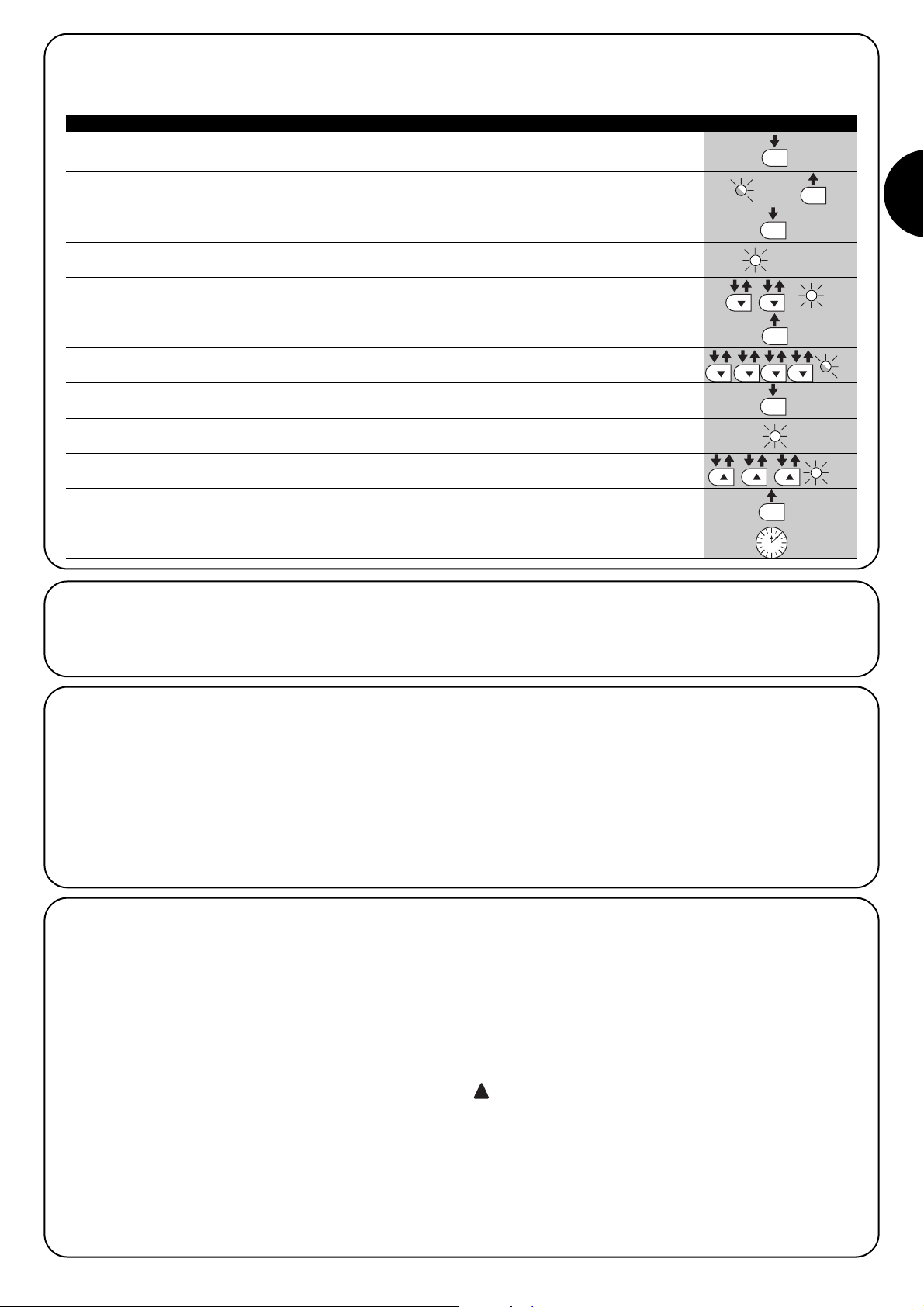
I
37
7.2.6) Esempio di programmazione secondo livello (parametri regolabili)
Come esempio viene riportata la sequenza di operazioni per cambiare l’impostazione di fabbrica dei parametri ed aumentare il “Tempo Pausa” a 60s (entrata su L1 e livello su L5) e ridurre la “Forza Motore” per cancelli leggeri (entrata su L5 e livello su L2).
1. Premere e tener premuto il tasto [Set] per circa 3s
3s
2. Rilasciare il tasto [Set] quando il led L1 inizia a lampeggiare
L1
3. Premere e mantenere premuto il tasto [Set]; il tasto [Set] va mantenuto premuto durante tutti
i passi 4 e 5
4. Attendere circa 3s fino a che si accenderà il led L3 che rappresenta il livello attuale
del “Tempo Pausa” L3 3s
5. Premere 2 volte il tasto [▼] per spostare il led acceso su L5 che rappresenta il nuovo valore
del “Tempo Pausa” L5
6. Rilasciare il tasto [Set]
7. Premere 4 volte il tasto [▼] per spostare il led lampeggiante sul led L5
L5
8. Premere e mantenere premuto il tasto [Set]; il tasto [Set] va mantenuto premuto durante
tutti i passi 9 e 10
9. Attendere circa 3s fino a che si accenderà il led L5 che rappresenta il livello attuale
della “Forza Motore” L3 3s
10. Premere 3 volte il tasto [▲] per spostare il led acceso su L2 che rappresenta il nuovo valore
della “Forza Motore” L2
11. Rilasciare il tasto [Set]
12. Attendere 10s per uscire dalla programmazione per fine tempo massimo
10s
Tabella N°17: esempio di programmazione secondo livello Esempio
SET
SET
SET
SET
SET
SET
7.3) Aggiunta o rimozione dispositivi
Ad una automazione con ROBUS350 è possibile aggiungere o
rimuovere dispositivi in qualsiasi momento. In particolare a “BLUEBUS” ed all’ingresso “STOP” possono essere collegati vari tipi di
dispositivi come indicato nei paragrafi “7.3.1 BlueBUS” e “7.3.2
Ingresso STOP”.
7.3.1) BlueBUS
BlueBUS è una tecnica che permette di effettuare i collegamenti dei
dispositivi compatibili con soli due conduttori sui quali transita sia l’alimentazione elettrica che i segnali di comunicazione. Tutti i dispositivi vengono collegati in parallelo sugli stessi 2 conduttori di BlueBUS
e senza necessità di rispettare alcuna polarità; ogni dispositivo viene
riconosciuto singolarmente poiché durante l’installazione gli viene
assegnato un indirizzo univoco. A BlueBUS si possono collegare ad
esempio: fotocellule, dispositivi di sicurezza, pulsanti di comando,
spie di segnalazione ecc.
La centrale di controllo di ROBUS350 riconosce uno ad uno tutti i
dispositivi collegati attraverso un’opportuna fase di apprendimento
ed è in grado di rilevare con estrema sicurezza tutte le possibili anomalie. Per questo motivo ogni volta che viene aggiunto o tolto un
dispositivo collegato a BlueBUS occorrerà eseguire nella centrale la
fase di apprendimento come descritto nel paragrafo “7.2.4 Apprendimento altri dispositivi”.
7.3.2) Ingresso STOP
STOP è l’ingresso che provoca l’arresto immediato della manovra
seguito da una breve inversione. A questo ingresso possono essere
collegati dispositivi con uscita a contatto normalmente aperto “NA”,
normalmente chiuso “NC” oppure dispositivi con uscita a resistenza
costante 8,2kΩ, ad esempio bordi sensibili.
Come per BlueBUS, la centrale riconosce il tipo di dispositivo collegato all’ingresso STOP durante la fase di apprendimento (vedere
paragrafo “7.2.4 Apprendimento altri dispositivi”); successivamente
viene provocato uno STOP quando si verifica una qualsiasi variazione rispetto allo stato appreso.
Con opportuni accorgimenti è possibile collegare all’ingresso STOP
più di un dispositivo, anche di tipo diverso:
• Più dispositivi NA si possono collegare in parallelo tra di loro sen-
za alcun limite di quantità.
• Più dispositivi NC si possono collegare in serie tra di loro senza
alcun limite di quantità.
• Due dispositivi con uscita a resistenza costante 8,2kΩ si possono
collegare in parallelo; se vi sono più di 2 dispositivi allora tutti devono essere collegati “in cascata” con una sola resistenza di terminazione da 8,2kΩ
• E’ possibile la combinazione di NA ed NC ponendo i 2 contatti in
parallelo con l’avvertenza di porre in serie al contatto NC una resistenza da 8,2kΩ (ciò rende possibile anche la combinazione di 3
dispositivi: NA, NC e 8,2kΩ).
Se l’ingresso STOP è usato per collegare dispositivi
con funzioni di sicurezza solo i dispositivi con uscita a
resistenza costante 8,2kΩ garantiscono la categoria 3 di
sicurezza ai guasti secondo la norma EN 954-1.
!
Page 38

38
FOTO
Fotocellula esterna h = 50
con intervento in chiusura
FOTO II
Fotocellula esterna h = 100
con intervento in chiusura
FOTO 1
Fotocellula interna h = 50
con intervento in chiusura
FOTO 1 II
Fotocellula interna h = 100
con intervento in chiusura
FOTO 2
Fotocellula esterna
con intervento in apertura
FOTO 2 II
Fotocellula interna
con intervento in apertura
FOTO 3
Fotocellula unica che copre tutto
l’automatismo
L’installazione di FOTO 3 assieme a FOTO II richiede che la
posizione degli elementi che compongono la fotocellula (TX-RX)
rispetti l’avvertenza riportata nel manuale di istruzioni delle fotocellule.
!
7.3.3) Fotocellule
Il sistema “BlueBUS” consente, tramite l’indirizzamento con gli
appositi ponticelli, il riconoscimento delle fotocellule da parte della
centrale e di assegnare la corretta funzione di rilevazione.
L’operazione di indirizzamento va fatta sia sul TX che sul RX (ponendo i ponticelli nello stesso modo) verificando che non vi siano altre
coppie di fotocellule con lo stesso indirizzo.
In un automatismo per cancelli scorrevoli con ROBUS350 è possibile installare le fotocellule secondo quanto rappresentato in figura 22.
Dopo l’installazione o la rimozione di fotocellule occorrerà eseguire
nella centrale la fase di apprendimento come descritto nel paragrafo
“7.3.4 Apprendimento altri dispositivi”.
22
Tabella N°18: indirizzi delle fotocellule
Fotocellula Ponticelli Fotocellula Ponticelli
7.3.4) Apprendimento altri dispositivi
Normalmente l’operazione di apprendimento dei dispositivi collegati a BlueBUS ed all’ingresso STOP viene eseguita durante la fase di installazione; tuttavia se vengono aggiunti o rimossi dispositivi è possibile rifare l’apprendimento nel seguente modo:
1. Premere e tenere premuti i tasti [▲] e [Set]
2. Rilasciare i tasti quando i led L1 e L2 iniziano a lampeggiare molto velocemente (dopo circa 3s)
L1 L2
3. Attendere alcuni secondi che la centrale finisca l’apprendimento dei dispositivi
4. Al termine dell’apprendimento i led L1 e L2 smetteranno di lampeggiare, il led STOP deve rimanere
acceso, mentre i led L1…L6 si accenderanno in base allo stato delle funzioni ON-OFF che rappresentano. L1 L2
Dopo aver aggiunto o rimosso dei dispositivi è necessario eseguire nuovamente il collaudo dell’automazione secondo
quanto indicato nel paragrafo “5.1 Collaudo”.
!
Tabella N°19: per l’apprendimento di altri dispositivi Esempio
SET
SET
7.4.1) Funzione “Apri sempre”
La funzione “Apri sempre” è una proprietà della centrale di controllo
che permette di comandare sempre una manovra di apertura quando il comando di “Passo-Passo” ha una durata superiore a 2 secondi; ciò è utile ad esempio per collegare al morsetto P.P. il contatto di
un orologio programmatore per mantenere aperto il cancello per una
certa fascia oraria.
Questa proprietà è valida qualunque sia la programmazione dell’ingresso di P.P. ad esclusione della programmazione come “Chiude”,
vedere parametro “Funzione P.P.” in tabella 14.
7.4.2) Funzione “Muovi comunque”
Nel caso in cui qualche dispositivo di sicurezza non dovesse funzionare correttamente o fosse fuori uso, è possibile comunque comandare e muovere il cancello in modalità “Uomo presente”.
Per i dettagli vedere il paragrafo “Comando con sicurezze fuori uso”
presente nell’allegato “Istruzioni ed avvertenze destinate all’utilizzatore del motoriduttore ROBUS”.
7.4) Funzioni particolari
Page 39

I
39
7.6) Risoluzione dei problemi
Nella tabella N°20 è possibile trovare utili indicazioni per affrontare gli
eventuali casi di malfunzionamento in cui è possibile incorrere durante l’installazione o in caso di guasto.
7.7) Diagnostica e segnalazioni
Alcuni dispositivi offrono direttamente delle segnalazioni particolari
attraverso le quali è possibile riconoscere lo stato di funzionamento
o dell’eventuale malfunzionamento.
24
Tabella N°20: ricerca guasti
Sintomi Verifiche consigliate
Il trasmettitore radio non comanda il cancello ed
il led sul trasmettitore non si accende.
Il trasmettitore radio non comanda il cancello
ma il led sul trasmettitore si accende.
Non si comanda nessuna manovra ed il led
“BLUEBUS” non lampeggia.
Non si comanda nessuna manovra ed il lampeggiante è spento.
Non si comanda nessuna manovra ed il lampeggiante fa alcuni lampeggi.
La manovra ha inizio ma subito dopo avviene
l’inversione
La manovra viene eseguita regolarmente ma il
lampeggiante non funziona.
La manovra viene eseguita regolarmente ma la
spia SCA non funziona.
Verificare se le pile del trasmettitore non siano scariche, eventualmente sostituirle.
Verificare se il trasmettitore è correttamente memorizzato nel ricevitore radio.
Verificare che ROBUS350 sia alimentato con la tensione di rete 230V.
Verificare che i fusibili non siano interrotti; in questo caso, verificare la causa del guasto
e poi sostituirli con altri dello stesso valore di corrente e caratteristiche.
Verificare che il comando venga effettivamente ricevuto. Se il comando giunge sull’ingresso PP il relativo led “PP” deve accendersi; se invece viene utilizzato il trasmettitore
radio, il led “Blubus” deve fare due lampeggi veloci.
Contare il numero di lampeggi e verificare secondo quanto riportato in tabella N°21.
La forza selezionata potrebbe essere troppo bassa per il tipo di cancello. Verificare se
ci sono degli ostacoli ed eventualmente selezionare una forza superiore.
Verificare che durante la manovra vi sia tensione sul morsetto FLASH del lampeggiante
(essendo intermittente il valore di tensione non è significativo: circa 10-30Vcc); se c’è tensione, il problema è dovuto alla lampada che dovrà essere sostituita con una di uguali
caratteristiche; se non c’è tensione, potrebbe essersi verificato un sovraccarico sull’uscita
FLASH, verificare che non vi sia corto circuito sul cavo.
Verificare il tipo di funzione programmata per l’uscita SCA (Tabella N°14)
Quando la spia dovrebbe essere accesa, verificare vi sia tensione sul morsetto SCA (circa
24Vcc); se c’è tensione, il problema è dovuto alla spia che dovrà essere sostituita con una
di uguali caratteristiche; se non c’è tensione, potrebbe essersi verificato un sovraccarico
sull’uscita SCA. verificare che non vi sia corto circuito sul cavo.
7.5) Collegamento altri dispositivi
Se vi fosse l’esigenza di alimentare dispositivi esterni ad esempio un
lettore di prossimità per tessere a transponder oppure la luce d’illuminazione del selettore a chiave è possibile prelevare l’alimentazione
come indicato in figura 23.
La tensione di alimentazione è 24Vcc -30% ÷ +50% con corrente
massima disponibile di 100mA.
-+
24Vcc
23
F2
F1
Page 40

40
Led BLUEBUS Causa AZIONE
Led STOP Causa AZIONE
Led P.P. Causa AZIONE
Spento
7.7.2) Segnalazioni sulla centrale
Nella centrale di ROBUS350 ci sono una serie di LED ognuno dei
quali può dare delle segnalazioni particolari, sia nel funzionamento
normale che in caso di anomalia.
Tabella N°22: led sui morsetti della centrale
Anomalia
Verificare se c’è alimentazione; verificare che i fusibili non siano intervenuti; nel
caso, verificare la causa del guasto e poi sostituirli con altri dello stesso valore
Acceso Anomalia grave
C’è una anomalia grave; provare a spegnere per qualche secondo la centrale;
se lo stato permane c’è un guasto e occorre sostituire la scheda elettronica
Un lampeggio al secondo Tutto OK Funzionamento normale della centrale
2 lampeggi veloci
E’ avvenuta una variazione
dello stato degli ingressi
E’ normale quando avviene un cambiamento di uno degli ingressi: P.P., STOP,
intervento delle fotocellule o viene utilizzato il trasmettitore radio
Serie di lampeggi separati da
una pausa di un secondo
Varie E’ la stessa segnalazione che c’è sul lampeggiante Vedere Tabella N°21
Spento
Intervento dell’ingresso di
STOP
Verificare i dispositivi collegati all’ingresso di STOP
Acceso Tutto OK Ingresso STOP attivo
Spento Tutto OK Ingresso PP non attivo
Acceso
Intervento dell’ingresso di
PP
E’ normale se è effettivamente attivo il dispositivo collegato all’ingresso PP
25
6 lampeggi
pausa di 1 secondo
6 lampeggi
All’inizio della manovra, la verifica dei dispositivi collegati a BLUEBUS non
corrisponde a quelli memorizzati durante la fase di apprendimento. E’ possibile vi siano dispositivi guasti, verificare e sostituire; se sono state fatte delle
modifiche occorre rifare l’apprendimento
7.7.1) Segnalazioni con il lampeggiante
Il segnalatore lampeggiante FLASH durante la manovra esegue un lampeggio ogni secondo; quando accadono delle anomalie, vengono
emessi dei lampeggi più brevi; i lampeggi si ripetono due volte, separati da una pausa di un secondo.
Tabella N°21: segnalazioni sul lampeggiante FLASH
Lampeggi veloci Causa AZIONE
1 lampeggio
pausa di 1 secondo
1 lampeggio
Errore sul BluBUS
2 lampeggi
pausa di 1 secondo
2 lampeggi
Intervento di una fotocellula
All’inizio della manovra una o più fotocellule non danno il consenso al movimento, verificare se ci sono ostacoli.
Durante il movimento è normale se effettivamente è presente un ostacolo.
3 lampeggi
pausa di 1 secondo
3 lampeggi
Intervento del limitatore
della “Forza Motore”
Durante il movimento il cancello ha incontrato un maggiore attrito;
verificare la causa
4 lampeggi
pausa di 1 secondo
4 lampeggi
Intervento dell’ingresso di
STOP
All’inizio della manovra o durante il movimento c’è stato un intervento dell’ingresso di STOP; verificare la causa
5 lampeggi
pausa di 1 secondo
5 lampeggi
Errore nei parametri interni
della centrale elettronica
Attendere almeno 30 secondi e riprovare a dare un comando; se lo stato
rimane potrebbe esserci un guasto grave ed occorre sostituire la scheda elettronica
Superato il limite massimo
di manovre per ora.
Attendere alcuni minuti che il limitatore di manovre ritorni sotto il limite massimo
7 lampeggi
pausa di 1 secondo
7 lampeggii
Errore nei circuiti elettrici
interni
Scollegare tutti i circuiti di alimentazione per qualche secondi poi riprovare a
dare un comando; se lo stato rimane potrebbe esserci un guasto grave ed
occorre sostituire la scheda elettronica
Page 41
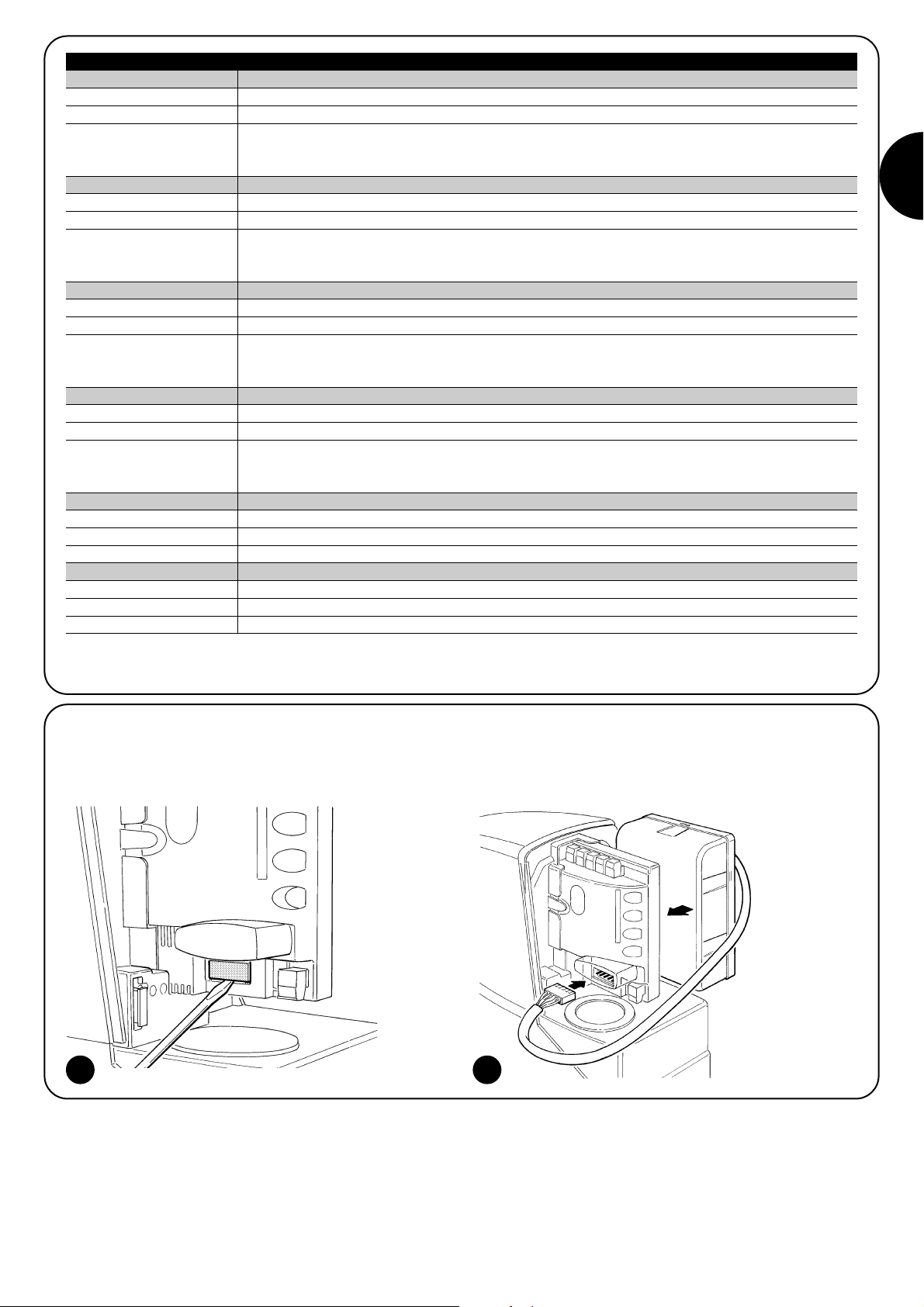
I
41
7.8) Accessori
Per ROBUS350 sono previsti i seguenti accessori opzionali:
• PS124 Batteria tampone 24V - 1,2Ah con caricabatteria integrato.
Consultare il catalogo prodotti di Nice S.p.a. per l’elenco completo
ed aggiornato degli accessori.
26
Led 1 Descrizione
• Programmazione delle funzioni in corso
• Se lampeggia assieme ad L4 indica che è necessario eseguire la fase di apprendimento della lunghezza
dell’anta (vedere paragrafo “4.4 Apprendimento lunghezza dell’ anta”).
Led L6 Descrizione
Led L5 Descrizione
Led L3 Descrizione
Led L2 Descrizione
Led L4 Descrizione
Durante il funzionamento normale indica “Spunto” non attivo.Spento
Spento
Tabella N°23: led sui tasti della centrale
Durante il funzionamento normale indica “Chiusura automatica” non attiva
Durante il funzionamento normale indica “Chiusura automatica” attiva
• Programmazione delle funzioni in corso
• lampeggia assieme ad L2 indica che è necessario eseguire la fase di apprendimento dei dispositivi
(vedere paragrafo “4.3 Apprendimento dei dispositivi”).
Acceso
Lampeggia
Spento Durante il funzionamento normale indica “Richiudi Dopo Foto” non attivo.
Durante il funzionamento normale indica “Richiudi Dopo Foto” attivo.
• Programmazione delle funzioni in corso
• Se lampeggia assieme ad L1 indica che è necessario eseguire la fase di apprendimento dei dispositivi
(vedere paragrafo “4.3 Apprendimento dei dispositivi”).
Acceso
Lampeggia
Spento Durante il funzionamento normale indica “Chiude Sempre” non attivo.
Durante il funzionamento normale indica “Chiude Sempre” attivo.
Durante il funzionamento normale indica “Stand-By” non attivo.
Durante il funzionamento normale indica “Stand-By” attivo.
• Programmazione delle funzioni in corso
• Se lampeggia assieme ad L3 indica che è necessario eseguire la fase di apprendimento della lunghezza
dell’anta (vedere paragrafo “4.4 Apprendimento lunghezza dell’ anta”).
Acceso
Lampeggia
Spento
Acceso
Lampeggia
Durante il funzionamento normale indica “Spunto” attivo.
Programmazione delle funzioni in corso
Acceso
Lampeggia
Durante il funzionamento normale indica “Prelampeggio” non attivo.
Durante il funzionamento normale indica “Prelampeggio” attivo.
Programmazione delle funzioni in corso
Spento
Acceso
Lampeggia
27
Page 42

Potenza irradiata
Dimensioni e peso
Da 100 a 150m, questa distanza può variare in presenza di ostacoli e disturbi elettromagnetici eventualmente presenti ed è influenzata dalla posizione dell'antenna ricevente
Utilizzo in atmosfera particolarmente acida o
salina o potenzialmente esplosiva
330 x 195 h 277; 8Kg
Con lo scopo di migliorare i propri prodotti, Nice S.p.a si riserva il diritto modifiche le caratteristiche tecniche in qualsiasi momento e senza
preavviso pur mantenendo funzionalità e destinazione d’uso.
Tutte le caratteristiche tecniche riportate si riferiscono alla temperatura ambientale di 20°C (±5°C).
8) Caratteristiche tecniche
Tipologia
Caratteristiche tecniche: ROBUS350
Motoriduttore elettromeccanico per il movimento automatico di cancelli scorrevoli per uso
residenziale completo di centrale elettronica di controllo
Pignone Z: 15; Modulo: 4; Passo: 12,6mm; Diametro primitivo: 60mm
Coppia massima allo spunto
10Nm; corrispondente alla capacità di mettere in movimento un’anta con attrito statico fino a 333N
Coppia nominale
6Nm; corrispondente alla capacità mantenere in movimento un’anta con attrito dinamico fino a 200N
Velocità alla coppia nominale
0,18m/s
Velocità a vuoto
(la centrale consente di programmare 6 velocità pari a circa: 100, 85, 70, 55, 45, 30%)
0,34m/s
Frequenza massima cicli di funzionamento 50 cicli /giorno (la centrale limita i cicli al massimo previsto nelle tabelle N°1 e N°2)
Tempo massimo funzionamento continuo
10 minuti (la centrale limita il funzionamento continuo al massimo previsto nelle tabelle N°1
e N°2)
Limiti d’impiego
Generalmente ROBUS350 è in grado di automatizzare cancelli con peso fino a 350Kg
oppure lunghezza fino a 7m e secondo i limiti previsti nelle tabelle N°1 e N°2.
Potenza massima assorbita 250VA
Classe di isolamento 1 (è necessaria la messa a terra di sicurezza)
Alimentazione di emergenza Con accessorio opzionale PS124
Uscita lampeggiante Per 1 lampeggiante LUCYB (lampada 12V, 21W)
Uscita BLUEBUS Una uscita con carico massimo di 15 unità BlueBus
Ingresso STOP
Per contatti normalmente chiusi, normalmente aperti oppure a resistenza costante 8,2KΩ; in autoap-
prendimento (una variazione rispetto allo stato memorizzato provoca il comando “STOP”)
Ingresso PP Per contatti normalmente aperti (la chiusura del contatto provoca il comando P.P.)
Ingresso ANTENNA Radio 52Ω per cavo tipo RG58 o simili
Alimentazione ROBUS350
Alimentazione ROBUS350/V1
230Vac (+10% +15%) 50/60Hz.
120Vac (+10% +15%) 50/60Hz.
Funzioni programmabili 6 funzioni di tipo ON-OFF e 6 funzioni regolabili (vedere tabelle N° 12 e N° 14)
Temperatura di funzionamento -20°C ÷ 50°C
No
Grado di protezione IP 44
Dimensioni e peso
Funzioni in autoapprendimento
Autoapprendimento dei dispositivi collegati all'uscita BlueBUS
Autoapprendimento del tipo di dispositivo di "STOP" (contatto NA, NC o resistenza 8,2kΩ)
Autoapprendimento della lunghezza del cancello e calcolo dei punti di rallentamento ed
apertura parziale
Uscite 4 (su connettore SM)
Temperatura di funzionamento
-10°C ÷ 55°C
Tipologia
Caratteristiche tecniche ricevitore radio: SMXI ricevitore radio: SMXIS
Ricevitore a 4 canali per radiocomando
Frequenza 433.92MHz
Codifica Digitale Rolling code a 52 Bit, tipo FLOR Digitale Rolling code a 64 Bit, tipo SMILO
Compatibilità trasmettitori
FLOR, VERY VR; solo gruppo singolo: ERGO,
PLANO, PLANOTIME
SMILO
Trasmettitori memorizzabili Fino a 256 se memorizzati in Modo I
Impedenza di ingresso 52Ω
Sensibilità migliore di 0.5µV
Portata dei trasmettitori
72 x 40 h 18mm / 30g Diametro 48 h14mm / 19g
Grado di protezione IP 40 (utilizzo in casa o ambienti protetti)
Temperatura di funzionamento
-40°C ÷ 85°C
Tipologia Trasmettitore 2 canali per radiocomando
Frequenza 433.92MHz
Codifica Digitale Rolling code a 52 Bit, tipo FLOR Digitale Rolling code a 64 Bit, tipo SMILO
Tasti 2
Alimentazione 12Vdc con batteria tipo 23A
Assorbimento 25mA
Durata della batteria
1 anno, stimata su una base di 20 comandi/giorno della durata di 1s a 20°C (alle basse temperature l’effi-
cienza della batteria diminuisce)
100µW
Caratteristiche tecniche trasmettitore: FLO2R-S trasmettitore: SM2
42
Page 43

I
43
GB
Complimenti per aver scelto per la vostra automa-
zione un prodotto Nice! Nice S.p.a. produce componenti per l’automazione di cancelli, porte,serrande,
tapparelle e tende da sole: motoriduttori, centrali di
comando,radiocomandi, lampeggianti, fotocellule e
accessori. Nice utilizza solo materiali e lavorazioni di
qualità, e per vocazione ricerca soluzioni innovative
che semplifichino al massimo l’utilizzo delle sue apparecchiature, curate nelle soluzioni tecniche, estetiche,
ergonomiche: nella grande gamma Nice il vostro installatore avrà senz’altro scelto il prodotto più adatto alle
vostre esigenze. Nice non è però il produttore della
vostra automazione, che è invece il risultato di un’opera di analisi, valutazione, scelta dei materiali, e realizzazione dell’impianto eseguita dal vostro installatore di
fiducia. Ogni automazione è unica e solo il vostro
installatore possiede l’esperienza e la professionalità
necessarie ad eseguire un impianto secondo le vostre
esigenze, sicuro ed affidabile nel tempo, e soprattutto
a regola d’arte, rispondente cioè alle normative in vigore. Un impianto di automazione è una bella comodità,
oltre che un valido sistema di sicurezza e, con poche,
semplici attenzioni, è destinato a durare negli anni.
Anche se l’automazione in vostro possesso soddisfa il
livello di sicurezza richiesto dalle normative, questo
non esclude l’esistenza di un “rischio residuo”, cioè la
possibilità che si possano generare situazioni di pericolo, solitamente dovute ad un utilizzo incosciente o
addirittura errato, per questo motivo desideriamo darvi alcuni consigli sui comportamenti da seguire per evitare ogni inconveniente:
•Prima di usare per la prima volta l’automazio-
ne, fatevi spiegare dall’installatore l’origine dei rischi
residui, e dedicate qualche minuto alla lettura del
manuale di istruzioni ed avvertenze per l’utiliz-
zatore consegnatovi dall’installatore. Conservate il
manuale per ogni dubbio futuro e consegnatelo ad un
eventuale nuovo proprietario dell’automazione.
•La vostra automazione è un macchinario che
esegue fedelmente i vostri comandi; un uso
incosciente ed improprio può farlo diventare pericoloso: non comandate il movimento dell’automazione se
nel suo raggio di azione si trovano persone, animali o
cose.
•Bambini: un impianto di automazione garantisce un
alto grado di sicurezza, impedendo con i suoi sistemi
di rilevazione il movimento in presenza di persone o
cose, e garantendo un’attivazione sempre prevedibile e sicura. È comunque prudente vietare ai bambini
di giocare in prossimità dell’automazione e per evitare attivazioni involontarie non lasciare i telecomandi
alla loro portata: non è un gioco!
•Anomalie: Non appena notate qualunque compor-
tamento anomalo da parte dell’automazione, togliete
alimentazione elettrica all’impianto ed eseguite lo
sblocco manuale. Non tentate da soli alcuna ripara-
zione, ma richiedete l’intervento del vostro installatore di fiducia: nel frattempo l’impianto può funzionare
come un’apertura non automatizzata, una volta
sbloccato il motoriduttore come descritto più avanti.
•Manutenzione: Come ogni macchinario la vostra
automazione ha bisogno di una manutenzione periodica affinché possa funzionare più a lungo possibile
ed in completa sicurezza. Concordate con il vostro
installatore un piano di manutenzione con frequenza
periodica; Nice consiglia un intervento ogni 6 mesi
per un normale utilizzo domestico, ma questo periodo può variare in funzione dell’intensità d’uso. Qualunque intervento di controllo, manutenzione o riparazione deve essere eseguito solo da personale qualificato.
•Anche se ritenete di saperlo fare, non modificate l’impianto ed i parametri di programmazione e di regolazione dell’automazione: la responsabilità è del vostro
installatore.
• Il collaudo, le manutenzioni periodiche e le eventuali
riparazioni devono essere documentate da chi le esegue e i documenti conservati dal proprietario dell’impianto.
Gli unici interventi che vi sono possibili e vi consigliamo di effettuare periodicamente sono la pulizia dei
vetrini delle fotocellule e la rimozione di eventuali foglie
o sassi che potrebbero ostacolare l’automatismo. Per
impedire che qualcuno possa azionare il cancello, prima di procedere, ricordatevi di sbloccare l’automa-
tismo (come descritto più avanti) e di utilizzare per la
pulizia solamente un panno leggermente inumidito con
acqua.
• Smaltimento: Al termine della vita dell’automazione, assicuratevi che lo smantellamento sia eseguito
da personale qualificato e che i materiali vengano riciclati o smaltiti secondo le norme valide a livello locale.
• In caso di rotture o assenza di alimentazione:
Attendendo l’intervento del vostro installatore, o il
ritorno dell’energia elettrica se l’impianto non è dotato di batterie tampone, l’automazione può essere
azionata come una qualunque apertura non automatizzata. Per fare ciò è necessario eseguire lo sblocco
manuale (unico intervento consentito all’utente sull’automazione): tale operazione è stata particolarmente studiata da Nice per assicurarvi sempre la
massima facilità di utilizzo, senza uso di attrezzi particolari o necessità di sforzo fisico.
Istruzioni ed avvertenze destinate all’utilizzatore del motoriduttore ROBUS
Page 44
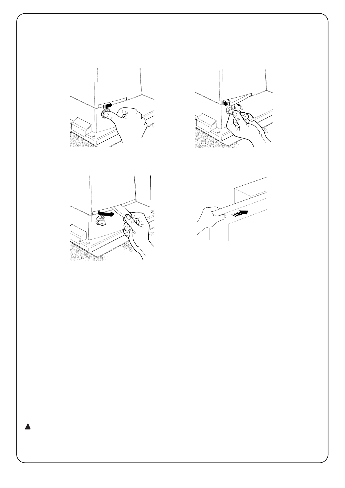
44
Sblocco e movimento manuale: prima di eseguire questa operazione porre attenzione che lo sblocco può
avvenire solo quando l’anta è ferma.
Per bloccare: eseguire, al contrario le stesse operazioni
Comando con sicurezze fuori uso: nel caso i
dispositivi di sicurezza presenti nel cancello non
dovessero funzionare correttamente è possibile
comunque comandare il cancello.
• Azionare il comando del cancello (col telecomando,
col selettore a chiave, ecc.); se tutto è a posto il
cancello si aprirà o chiuderà normalmente, altrimenti il lampeggiante farà alcuni lampeggi e la manovra
non partirà (il numero di lampeggi dipende dal motivo per cui la manovra non può partire).
• In questo caso, entro tre secondi si deve azionare
nuovamente e tenere azionato il comando.
• Dopo circa 2s inizierà il movimento del cancello in
modalità a “uomo presente”, cioè finché si mantiene
il comando, il cancello continuerà a muoversi; appena il comando viene rilasciato, il cancello si ferma.
Con le sicurezze fuori uso è necessario far
riparare quanto prima l’automatismo.
Sostituzione pila del telecomando: se il vostro
radiocomando dopo qualche tempo vi sembra funzionare peggio, oppure non funzionare affatto, potrebbe
semplicemente dipendere dall’esaurimento della pila (a
seconda dell’uso, possono trascorrere da diversi mesi
fino ad oltre un anno). Ve ne potete accorgere dal fatto che la spia di conferma della trasmissione non si
accende, è fioca, oppure si accende solo per un breve
istante. Prima di rivolgervi all’installatore provate a
scambiare la pila con quella di un altro trasmettitore
eventualmente funzionante: se questa fosse la causa
dell’anomalia, sarà sufficiente sostituire la pila con altra
dello stesso tipo.
Le pile contengono sostanze inquinanti: non gettarle
nei rifiuti comuni ma utilizzare i metodi previsti dai
regolamenti locali.
Siete soddisfatti? Nel caso voleste aggiungere nella vostra casa un nuovo impianto di automazione, rivolgendovi allo stesso installatore e a Nice vi garantirete,
oltre che la consulenza di uno specialista e i prodotti
più evoluti del mercato, il migliore funzionamento e la
massima compatibilità delle automazioni.
Vi ringraziamo per aver letto queste raccomandazioni,
e vi auguriamo la massima soddisfazione dal vostro
nuovo impianto: per ogni esigenza presente o futura
rivolgetevi con fiducia al vostro installatore.
!
1 Far scorrere il dischetto copri serratura. 2 Inserire e ruotare la chiave in senso orario
3 Tirare la maniglia di sblocco 4 Muovere manualmente l’anta
Page 45

Page 46

46
7 Approfondissements 56
7.1 Touches de programmation 56
7.2 Programmation 56
7.2.1 Fonctions premier niveau (fonctions ON-OFF) 56
7.2.2 Programmation du premier niveau
(fonctions ON-OFF) 57
7.2.3 Fonctions deuxième niveau
(paramètres réglables) 57
7.2.4 Programmation deuxième niveau
(paramètres réglables) 58
7.2.5 Exemple de programmation premier niveau
(fonctions ON-OFF) 58
7.2.6 Exemple de programmation deuxième niveau
(paramètres réglables) 59
7.3 Ajout ou enlèvement de dispositifs 59
7.3.1 BlueBUS 59
7.3.2 Entrée STOP 59
7.3.3 Photocellules 60
7.3.4 Reconnaissance d’autres dispositifs 60
7.4 Fonctions particulières 60
7.4.1 Fonction “Ouvre toujours” 60
7.4.2 Fonction “Manœuvre dans tous les cas” 60
7.5 Connexion d’autres dispositifs 61
7.6 Résolution des problèmes 61
7.7 Diagnostic signalisations 61
7.7.1 Signalisations avec le clignotant 62
7.7.2 Signalisations sur la logique de commande 62
7.8 Accessoires 63
8 Caractéristiques techniques 64
Instructions et recommandations destinées à
l’utilisateur de l’opérateur ROBUS 65
Table des matières: page
1 Avertissements 47
2 Description du produit et type d’utilisation 47
2.1 Limites d’utilisation 47
2.2 Installation typique 48
2.3 Liste des câbles 48
3 Installation 48
3.1 Contrôles préliminaires 49
3.2 Fixation de l’opérateur 49
3.3 Installation des divers dispositifs 50
3.4 Connexions électriques 50
3.5 Description des connexions électriques 51
4 Contrôles finaux et mise en service 51
4.1 Sélection de la direction 51
4.2 Branchement au secteur 52
4.3 Reconnaissance des dispositifs 52
4.4 Vérification du mouvement du portail 52
4.5 Vérification du mouvement du portail 52
4.6 Fonctions préprogrammées 52
4.7 Mémorisation des émetteurs radio 53
4.7.1 Mémorisation en Mode I 53
4.7.2 Mémorisation en Mode II 53
4.7.3 Mémorisation “à distance” 45
4.7.4 Effacement des émetteurs radio 54
4.7.5 Déclaration de conformité récepteur radio 54
5 Essai et mise en service 55
5.1 Essai 55
5.2 Mise en service 55
6 Maintenance et mise au rebut 55
6.1 Maintenance 55
6.2 Mise au rebut 55
Robus350
Page 47

F
47
2.1) Limites d’utilisation
Les données relatives aux performances de ROBUS350 figurent
dans le chapitre “8 Caractéristiques techniques” et sont les seules
valeurs qui permettent d’évaluer correctement si l’opérateur est
adapté à l’application.
Généralement ROBUS350 est en mesure d’automatiser des portails
pesant jusqu’à 350 kg ou mesurant jusqu’à 15 m suivant les indications des tableaux n°1 et n°2.
La longueur du portail permet de calculer le nombre maximum de
cycles à l’heure et de cycles consécutifs tandis que le poids permet
de calculer le pourcentage de réduction des cycles et la vitesse
maximum admissible; par exemple, si le portail mesure 5 m de long,
on peut avoir 10 cycles/heure et 6 cycles consécutifs mais si le portail pèse 240 kg, il faut les réduire à 80%, soit 8 cycles/heure et environ 5 cycles consécutifs tandis que la vitesse maximum admissible
est V5: très rapide. Pour éviter les surchauffes, la logique de com-
mande prévoit un limiteur qui se base sur l’effort du moteur et la durée
des cycles en intervenant quand la limite maximum est dépassée.
Longueur du portail en mètres
cycles/heure maximums
cycles consécutifs maximums
Jusqu’à 4 30 20
3÷5 18 12
5÷6 15 10
6÷7 12 8
1) Avertissements
Ce manuel d’instructions contient des informations importantes concernant
la sécurité pour l’installation, il faut lire toutes les instructions avant de procéder à l’installation. Conserver avec soin ce manuel également pour des
consultations futures.
Compte tenu des dangers qui peuvent se vérifier durant l’installation et l’utilisation de ROBUS350, pour le maximum de sécurité il faut que l’installation
soit faite dans le plein respect des lois, normes et règlements. Dans ce chapitre, nous donnons des recommandations d’ordre général; d’autres recommandations importantes se trouvent dans les chapitres “3.1 Contrôles préliminaires”; “Essai et mise en service”.
d’après la législation européenne la plus récente, la réalisation d’une porte ou d’un portail automatique possède les caractéristiques prévues par la Directive 98/37/CE (Directive
Machines) et en particulier par les normes EN 12445, EN 12453
et EN 12635 qui permettent de déclarer la présomption de
conformité.
D’autres informations et les conseils pour l’analyse des risques et la réalisation du dossier technique sont disponibles sur le site: “www.niceforyou.com”.
• Le présent manuel est destiné uniquement au personnel technique qualifié
pour l’installation. À part l’encart spécifique “Instructions et recommandations destinées à l’utilisateur de l’opérateur ROBUS” qui sera détaché par
l’installateur, aucune autre information contenue dans la présente notice ne
peut être considérée comme intéressante pour l’utilisateur final!
• Une utilisation de ROBUS350 différente de ce qui est prévu dans cette noti-
ce est interdite; des utilisations impropres peuvent être source de dangers
ou de dommages aux personnes et aux choses.
• Avant de commencer l’installation, il faut effectuer l’analyse des
risques comprenant la liste des conditions de sécurité requises par
l’annexe I de la Directive Machines, en indiquant les solutions adoptées. Nous rappelons que l’analyse des risques est l’un des documents qui constituent le “dossier technique” de l’automatisation.
• Vérifier la nécessité d’autres dispositifs pour compléter l’automatisation
avec ROBUS350 suivant les conditions spécifiques de l’application et les
risques présents; il faut considérer par exemple les risques d’impact, écrasement, cisaillement, coincement, etc., et d’autres dangers en général.
• Ne pas effectuer de modifications sur aucune des parties si elles ne sont
pas prévues dans le présent manuel. Des opérations de ce type entraîneront obligatoirement des problèmes de fonctionnement. NICE décline
toute responsabilité pour les dommages dérivant de produits modifiés.
• Pendant l’installation et l’utilisation, éviter que des parties solides ou
liquides puissent pénétrer à l’intérieur de la logique de commande ou
d’autres composants ouverts; s’adresser éventuellement au service
d’assistance NICE; l’utilisation de ROBUS350 dans de telles circonstances peut créer des situations de danger.
• L’automatisme ne peut pas être utilisé avant d’avoir effectué la mise en
service comme l’explique le chapitre: “5 Essai et mise en service”.
• L’emballage de ROBUS350 doit être mis au rebut dans le plein respect
de la réglementation locale.
• Dans le cas de panne qui ne peut pas être résolue avec les informations données dans ce manuel, contacter le service après-vente NICE.
• Si l’intervention de disjoncteurs ou de fusibles se vérifie, avant de les
réarmer, il faut identifier et éliminer la panne.
• Avant d’accéder aux bornes situées sous le carter de ROBUS350,
déconnecter tous les circuits d’alimentation; si le dispositif de déconnexion n’est pas visible, accrocher un panonceau: “ATTENTION
MAINTENANCE EN COURS”.
!
ROBUS350 est un opérateur électromécanique pour la manœuvre automatique
de portails coulissants pour usage résidentiel, il dispose d’une logique électronique de commande et d’un récepteur pour radiocommande. Les connexions
électriques vers les dispositifs extérieurs sont simplifiées grâce à la technique
“BlueBUS” qui permet de connecter plusieurs dispositifs avec seulement 2 fils.
ROBUS350 fonctionne à l’énergie électrique, en cas de coupure du courant, il est possible de débrayer l’opérateur avec une clé spéciale et de
manœuvrer le portail à la main. En alternative, on peut utiliser l’accessoire
en option: batterie tampon PS124 qui permet quelques manœuvres même
en l’absence du courant de secteur.
2) Description du produit et type d’utilisation
Tableau N°1: limites suivant la longueur du portail
Poids portail en kg Pourcentage cycles
Vitesse maximum admissible
Jusqu’à 200 100% V6 = Super rapide
200÷250 90% V5 = Très rapide
250÷300 80% V4 = Rapide
300÷350 70% V3 = Moyen
Tableau N°2: limites suivant le poids du portail
1
330 195
85
277
Page 48
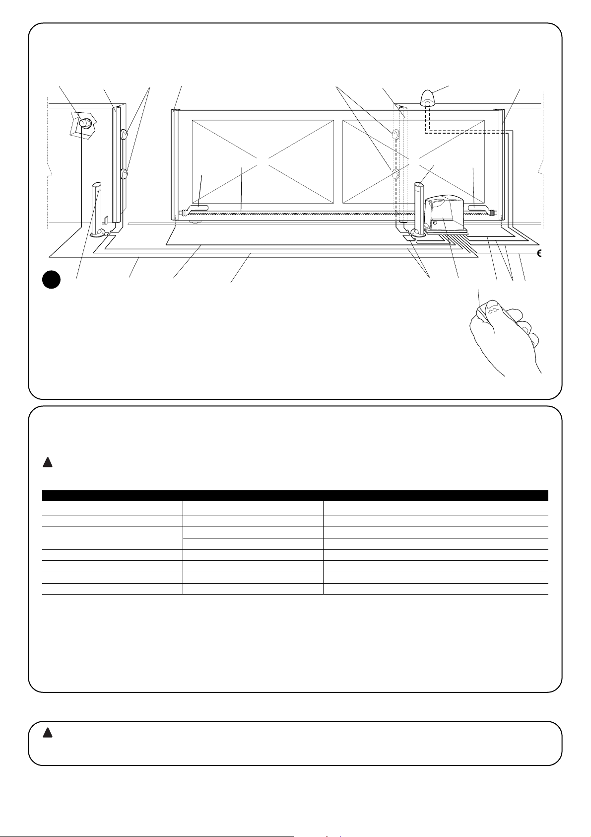
48
2.2) Installation typique
La figure 1 présente l’installation typique pour l’automatisation d’un portail de type coulissant utilisant ROBUS350.
2
1 Sélecteur à clé
2 Photocellules sur colonne
3 Photocellule
4 Bord primaire fixe (option)
5 Bord primaire mobile
6 Patte de fin de course “Ouvert”
7 Crémaillère
8 Bord secondaire fixe (option)
9 Clignotant avec antenne incorporée
10 ROBUS350
11 Patte de fin de course “Fermé”
12 Bord secondaire mobile (option)
13 Émetteur radio
2.3) Liste des câbles
Dans l’installation typique de la figure 1 sont indiqués aussi les câbles nécessaires pour les connexions des différents dispositifs; le tableau
n°3 indique les caractéristiques des câbles.
les câbles utilisés doivent être adaptés au type d’installation; par exemple, on conseille un câble type H03VV-F pour la pose
à l’intérieur ou H07RN-F pour la pose à l’extérieur.
!
Note 1: si le câble d’alimentation dépasse 30 m, il faut prévoir un câble avec une section plus grande, par exemple 3 x 2,5mm2et une mise
à la terre est nécessaire à proximité de l’automatisme.
Note 2: si le câble “BlueBUS” dépasse 30 m, jusqu’à n maximum de 50m, il faut prévoir un câble 2 x 1mm
2
.
Note 3: les deux câbles 2 x 0,5mm
2
peuvent être remplacés par un seul câble 4 x 0,5mm2.
Note 4: S’il y a plus d’un barre palpeuse, voir le chapitre “7.3.2 Entrée STOP” pour le type de connexion conseillée.
Note 5: pour la connexion des barres palpeuses mobiles sur les parties coulissantes, il faut utiliser des dispositifs ad hoc qui permettent la
connexion même quand le portail est en mouvement.
Connexion Type de câble Longueur maximum admise
A: Ligne électrique d’alimentation N°1 câble 3x1,5 mm
2
30m (note 1)
B: Clignotant avec antenne
N°1 câble 2x0,5 mm
2
20m
N°1 câble blindé type RG58 20m (longueur conseillée: moins de 5 m)
C: Photocellules N°1 câble 2x0,5 mm
2
30 m (note 2)
D: Sélecteur à clé N°2 câbles 2x0,5 mm2(note 3) 50m
E: Barres palpeuses fixes N°1 câble 2x0,5 mm2(note 4) 30m
F: Barres palpeuses mobiles N°1 câble 2 x 0,5 mm2(note 4) 30m (note 5)
Tableau N°3: liste des câbles
L’installation de ROBUS350 doit être effectuée par du personnel qualifié, dans le respect des lois, des normes et des règle-
ments ainsi que de toutes les instructions de ce manuel.
!
3) Installation
2
43 38
10
2
6
11
7
9
13
1251
E
F
D
C F
A
B
Page 49

F
49
3.2) Fixation de l’opérateur
Si la surface d’appui existe déjà, la fixation de l’opérateur doit être
effectuée directement sur la surface en utilisant des moyens adéquats par exemple avec des chevilles à expansion. Autrement, pour
fixer l’opérateur:
1. Creuser un trou de fondation de dimensions adéquates en suivant
les mesures indiquées dans la Figure 3 3.
2.Prévoir un ou plusieurs conduits pour le passage des câbles comme dans la Figure 4.
3.Assembler les deux agrafes sur la plaque de fondation en plaçant
un écrou en dessous et un au-dessus de la plaque; l’écrou sous
la plaque doit être vissé à fond de manière que la partie filetée de
l’agrafe dépasse d’environ 25÷35 mm sur le dessus de la plaque.
4.Effectuer la coulée en ciment et avant qu’il commence à prendre,
mettre la plaque de fondation en respectant les distances indiquées dans la figure 3; vérifier qu’elle est parallèle au portail et parfaitement de niveau. Attendre la prise complète du ciment.
5.Enlever les 2 écrous sur le dessus de la plaque puis y poser l’opérateur; vérifier qu’il est parfaitement parallèle au portail puis visser
légèrement les 2 écrous et les rondelles fournies comme dans la
figure 7.
3.1) Contrôles préliminaires
Avant de continuer l’installation de ROBUS350 il faut effectuer les
contrôles suivants:
• Vérifier que tout le matériel à utiliser est en excellent état, adapté
à l’usage et conforme aux normes.
• Vérifier que la structure du portail est adaptée pour être équipée
d’un automatisme.
• Vérifier que le poids et les dimensions du portail rentrent dans les
limites d’utilisation indiquées au chapitre “2.1 Limites d’utilisation”.
• Vérifier, en comparant avec les valeurs figurant dans le chapitre “8
Caractéristiques techniques”, que la friction statique (c’est-à-dire
la force nécessaire pour mettre le portail en mouvement) est inférieure à la moitié du “Couple maximum” et que la friction dynamique (c’est-à-dire la force nécessaire pour maintenir le portail en
mouvement) est inférieure à la moitié du “Couple nominal”; on
conseille une marge de 50% sur les forces car les conditions climatiques adverses peuvent faire augmenter les frictions.
• Vérifier que dans la course du portail, aussi bien en fermeture
qu’en ouverture, il n’y a pas de points présentant une plus grande
friction.
• Vérifier que le portail ne risque pas de dérailler et de sortir des rails
de guidage.
• Vérifier la robustesse des butées mécaniques de limitation de la
course en contrôlant qu’il n’y a pas de déformations même en cas
de heurt violent du portail sur la butée.
• Vérifier que le portail est bien équilibré, c’est-à-dire qu’il ne doit
pas bouger s’il est laissé arrêté dans une position quelconque.
• Vérifier que la zone de fixation de l’opérateur n’est pas sujette à
inondation; éventuellement, monter l’opérateur suffisamment soulevé par rapport au sol.
• Vérifier que la zone de fixation de l’opérateur permet la manœuvre
de débrayage de manière facile et sûre.
• Vérifier que les points de fixation des différents dispositifs se trouvent dans des endroits à l’abri des chocs et que les surfaces sont
suffisamment solides.
• Éviter que les parties de l’automatisme puissent être immergées
dans l’eau ou dans d’autres substances liquides.
• Ne pas placer ROBUS350 à proximité de flammes ou de sources
de chaleur, dans des atmosphères potentiellement explosives,
particulièrement acides ou salines; cela pourrait endommager
ROBUS350 et causer des problèmes de fonctionnement, provoquer un incendie ou des situations de danger.
• Si le portail coulissant est muni d’un portillon pour le passage de
piétons incorporé ou dans la zone de manœuvre du portail, il faut
s’assurer que ce portillon ne gêne pas la course normale et prévoir éventuellement un système d’interverrouillage.
• Connecter la logique de commande à une ligne d’alimentation
électrique avec mise à la terre.
• La ligne d’alimentation électrique doit être protégée par un disjoncteur magnétothermique associé à un déclencheur différentiel.
• Sur la ligne d’alimentation du secteur électrique, il faut monter un
dispositif de déconnexion de l’alimentation (avec catégorie de surtension III, c’est-à-dire avec une distance entre les contacts d’au
moins 3,5 mm) ou bien un autre système équivalent par exemple
prise + fiche. Si le dispositif de déconnexion de l’alimentation ne
se trouve pas à proximité de l’automatisme, il faut disposer d’un
système de blocage contre la connexion accidentelle ou non autorisée.
3
4
5
6
192
330 0÷50
0÷50 330
192
0÷10
0÷10
25÷35
7
Page 50

50
3.3) Installation des divers dispositifs
Installer les autres dispositifs prévus en suivant les instructions respectives. Vérifier dans le paragraphe “3.5 Description des connexions électriques” et dans la figure 1 les dispositifs qui peuvent être connectés à ROBUS350.
pour éviter que le portail pèse trop sur l’opérateur, il
est important qu’il y ait un jeu d’1÷2 entre la crémaillère
et le pignon, comme dans la figure 10.
8. Faire coulisser le portail et utiliser toujours le pignon comme
référence pour fixer les autres éléments de la crémaillère.
9. Couper l’éventuelle partie de crémaillère qui dépasse sur le der-
nier segment.
10. Effectuer différentes manœuvres d’ouverture et de fermeture du
portail à la main et vérifier que la crémaillère coulisse alignée au
pignon avec un désalignement maximum de 5 mm, et qu’il y a
un jeu d’1÷2 mm entre le pignon et la crémaillère sur toute la
longueur.
11. Serrer énergiquement les écrous de fixation de l’opérateur en
s’assurant qu’il est bien fixé au sol; couvrir les écrous de fixation
avec les bouchons comme dans la figure 11.
12. Fixer avec leurs goujons respectifs les pattes de fin de course
d’“Ouverture” et de “Fermeture” aux extrémités de la crémaillère comme sur la figure 12. Considérer que quand les fins de
course interviennent, le portail coulissera sur encore 2-3 cm
environ. Il est donc conseillé de régler le positionnement des
pattes avec une bonne marge sur les butées mécaniques.
13. Bloquer l’opérateur comme l’indique le paragraphe “Débrayage
et mouvement manuel” dans le chapitre “Instructions et recommandations destinées à l’utilisateur de l’opérateur ROBUS”
!
8 9
10
11 12
Si la crémaillère est déjà présente, après avoir fixé l’opérateur, agir
sur les goujons de réglage comme dans la figure 8 pour mettre le
pignon de ROBUS350 à la hauteur qui convient en laissant 1÷2 mm
de jeu de la crémaillère.Autrement, pour fixer la crémaillère, il faut:
6. Débrayer l’opérateur suivant les indications du paragraphe
“Débrayage et manœuvre manuelle” dans le chapitre “Instructions et recommandations destinées à l’utilisateur de l’opérateur
ROBUS”.
7. Ouvrir complètement le portail, poser sur le pignon le premier
segment de crémaillère et vérifier que le début de la crémaillère
correspond au début du portail comme sur la figure 9. Vérifier la
présence d’un jeu d’1÷2 mm entre le pignon et la crémaillère,
puis fixer la crémaillère sur le portail avec des moyens adéquats.
1÷2
3.4) Connexions électriques
toutes les connexions électriques doivent être effectuées en l’absence de tension dans l’installation et avec
l’éventuelle batterie tampon déconnectée.
1. Pour éliminer le couvercle de protection et accéder à la logique
électronique de commande de ROBUS350 il faut enlever la vis sur
le côté et retirer le couvercle en le tirant vers le haut.
2. Enlever la membrane en caoutchouc qui bouche le trou pour le
passage des câbles et enfiler tous les câbles de connexion vers
les différents dispositifs en les laissant dépasser de 20÷30 cm.
Voir le tableau N°3 pour le type de câble et la figure 1 pour les
connexions.
3. Réunir avec un collier de serrage tous les câbles qui entrent dans
l’opérateur, placer le collier juste en dessous du trou d’entrée des
câbles. Sur la membrane de caoutchouc, découper un trou un
peu plus étroit que le diamètre des câbles regroupés et enfiler la
membrane le long des câbles jusqu’au collier; remettre ensuite la
membrane le trou pour le passage des câbles. Mettre un deuxième collier de serrage pour regrouper les câbles juste au-dessus
de la membrane.
4. Connecter le câble d’alimentation sur la borne prévue à cet effet
comme l’indique la figure 14 puis avec un collier de serrage, bloquer le câble au premier anneau serre-câbles.
5. Effectuer les connexions des autres câbles suivant le schéma de
la figure 15. Pour plus de commodité, les bornes peuvent être
extraites.
6. Après avoir terminé les connexions, bloquer avec des colliers de
serrage les câbles regroupés au deuxième anneau serre-câbles,
la partie du câble d’antenne en excès doit être bloquée avec les
autres câbles à l’aide d’un autre collier comme l’indique la figure
14.
!
Page 51

F
51
3.5) Description des connexions électriques
Ce paragraphe contient une brève description des connexions électriques; d’autres informations se trouvent dans le paragraphe “7.3
Ajout ou enlèvement de dispositifs”.
FLASH: sortie pour clignotant type “LUCYB” ou similaires avec
l’ampoule 12 V maximum 21 W.
S.C.A.: sortie “Voyant portail ouvert”; il est possible de connecter
une ampoule de signalisation 24 V maximum 4 W.
BLUEBUS: sur ces bornes, on peut connecter les dispositifs compatibles; ils sont tous connectés en parallèle avec seulement deux
conducteurs sur lesquels transitent aussi bien l’alimentation électrique que les signaux de communication. D’autres informations sur
BlueBUS se trouvent dans le paragraphe “7.3.1 BlueBUS”.
STOP: entrée pour dispositifs qui bloquent ou éventuellement arrêtent la manœuvre en cours; en adoptant certaines solutions sur l’entrée, il est possible de connecter des contacts type “Normalement
Fermé”, “Normalement Ouvert” ou des dispositifs à résistance
constante. D’autres informations sur STOP se trouvent dans le paragraphe “7.3.2 Entrée STOP”.
P. P.: entrée pour dispositifs qui commandent le mouvement; on
peut y connecter des contacts de type “Normalement Ouvert”.
ANTENNA: entrée pour la connexion de l’antenne pour récepteur
radio (l’antenne est incorporée sur LUCY B).
13
14
15
Avant de commencer la phase de contrôle et de mise en service de l’automatisme, il est conseillé de mettre le portail à mi-course environ
de manière qu’il puisse se déplacer aussi bien en ouverture qu’en fermeture.
4) Contrôles finaux et mise en service
4.1) Sélection de la direction
La direction de la manœuvre d’ouverture doit être choisie en fonction
de la position de l’opérateur par rapport au portail; si le portail doit
coulisser vers la gauche pour l’ouverture, il faut mettre le sélecteur
vers la gauche comme dans la figure 16, si le portail doit coulisser
vers la droite pour l’ouverture, il faut mettre le sélecteur vers la droite comme dans la figure 17.
16
17
LUCYB S.C.A. MOFB MOSE
Page 52

52
Dès que l’opérateur ROBUS350 est alimenté, il est conseillé de faire quelques vérifications élémentaires:
1. Vérifier que la led BLUEBUS clignote régulièrement à la fréquence d’un clignotement à la seconde.
2. Vérifier que les led sur les photocellules clignotent elles aussi
(aussi bien sur TX que sur RX); la fréquence de clignotement n’est
pas significative, elle est liée à d’autres facteurs.
3. Vérifier que le clignotant connecté à la sortie FLASH et que le
voyant connecté sur la sortie S.C.A. sont éteints.
Si ce n’est pas le cas, il faut couper immédiatement l’alimentation de
la logique de commande et contrôler plus attentivement les
connexions électriques.
D’autres informations utiles pour la recherche et le diagnostic des
pannes se trouvent dans le chapitre “7.6 Résolution des problèmes”.
4.2) Branchement au secteur
le branchement de ROBUS350 au secteur doit être effectué par du personnel expert et qualifié en possession des
caractéristiques requises et dans le plein respect des lois, normes et réglementations.
!
4.3) Reconnaissance des dispositifs
Après le branchement au secteur il faut faire reconnaître par la logique
de commande les dispositifs connectés aux entrées BLUEBUS et
STOP. Avant cette phase, les led L1 et L2 clignotent pour indiquer
qu’il faut effectuer la reconnaissance des dispositifs.
La phase de reconnaissance des dispositifs connectés peut être refaite à tout moment même après l’installation, par exemple si l’on ajoute un dispositif; pour effectuer la nouvelle reconnaissance, voir paragraphe “7.3.4
Reconnaissance d’autres dispositifs”
1. Presser et maintenir enfoncées les touches [▲] et [Set]
2. Relâcher les touches quand les led L1 et L2 commencent à clignoter très rapidement (au bout d’environ 3 s)
3. Attendre quelques secondes que la logique termine la reconnaissance des dispositifs
4. À la fin de la reconnaissance, la led STOP doit rester allumée, les led L1 et L2 s’éteindront (les led L3 et L4 com-
menceront éventuellement à clignoter)
4.4) Reconnaissance de la longueur du portail
Après la reconnaissance des dispositifs, les led L3 et L4 commenceront à clignoter; cela signifie qu’il faut faire reconnaître la longueur
du portail (distance entre le fin de course de fermeture et le fin de
course d’ouverture); cette mesure est nécessaire pour le calcul des
points de ralentissement et le point d’ouverture partielle.
1. Presser et maintenir enfoncées les touches [▼] et [Set]
2. Relâcher les touches quand la manœuvre commence (au bout d’environ 3 s)
3. Vérifier que la manœuvre en cours est une ouverture, autrement presser la touche [Stop] et relire attentivement
le paragraphe “4.1 Sélection de la direction”; puis répéter à partir du point 1.
4. Attendre que la logique complète la manœuvre d’ouverture jusqu’à ce que le fin de course d’ouverture soit
atteint; la manœuvre de fermeture commence juste après;
5. 5Attendre que la logique complète la manœuvre de fermeture.
4.5) Vérification du mouvement du portail
Après la reconnaissance de la longueur du portail, il est conseillé
d’effectuer quelques manœuvres pour vérifier que le mouvement du
portail est correct.
1. Presser la touche [Open] pour commander une manœuvre
d’ouverture; vérifier que l’ouverture du portail s’effectue régulièrement sans variation de vitesse; le portail ne doit ralentir que lorsqu’il se trouve 70÷50 cm avant le fin de course et il doit s’arrêter,
suite à l’intervention du fin de course, à 2÷3cm de la butée mécanique d’ouverture.
2.
Presser la touche [Close] pour commander une manœuvre de fermeture; vérifier que la fermeture du portail s’effectue régulièrement sans
variation de vitesse; le portail ne doit ralentir que lorsqu’il se trouve
70÷50 cm avant le fin de course et il doit s’arrêter, suite à l’intervention
du fin de course, à 2÷3cm de la butée mécanique de fermeture.
3. Durant la manœuvre, vérifier que le clignotant clignote à une fréquence régulière de 0,5 s. S’il est présent, contrôler également le
clignotement du voyant connecté à la borne SCA: clignotement
lent en ouverture, rapide en fermeture.
4. Effectuer différentes manœuvres d’ouverture et de fermeture pour
mettre en évidence les éventuels défauts de montage et de réglage ou d’autres anomalies comme par exemple les points de plus
grande friction.
5. Vérifier que les fixations de l’opérateur ROBUS350, de la crémaillère et des pattes de fin de course sont solides, stables et
suffisamment résistantes même en cas de brusques accélérations ou décélérations du mouvement du portail
4.6) Fonctions préprogrammées
La logique de commande de ROBUS350 dispose de certaines fonctions
programmable; en usine ces fonctions sont réglées suivant une configuration qui devrait satisfaire la plupart des automatisations; quoiqu’il en
soit, les fonctions peuvent être modifiées à tout moment à l’aide d’une
procédure de programmation particulière, voir pour cela le paragraphe
“7.2 Programmations”.
18
19
Si tout cela ne se vérifie pas, il faut couper immédiatement l’alimentation de la logique de commande et contrôler plus attentivement les connexions électriques. D’autres informations utiles se trouvent dans le chapitre “7.6
Résolution des problèmes”.
Page 53

F
53
N°1 Commande “PP”
N°2 Commande “Ouverture partielle”
N°3 Commande “Ouverture”
N°4 Commande “Fermeture”
Tableau N°5: commandes disponibles en Mode II
4.7) Mémorisation des émetteurs radio
Pour la commande à distance de ROBUS350, la logique de commande est munie d’un connecteur SM pour récepteurs radio type SMXI ou
SMXIS (voir fig. 20); chaque émetteur radio est reconnu par ce récepteur à travers un “code” distinct de tous les autres. Il faut donc effectuer une phase de “mémorisation” à travers laquelle le récepteur est préparé à reconnaître chaque émetteur. La mémorisation des émetteurs
peut se faire de deux manières:
Mode I: dans ce mode la fonction des touches de l’émetteur est
fixe et chaque touche correspond dans la logique à la commande
indiquée dans le tableau N°4; on effectue une unique phase pour
chaque émetteur dont sont mémorisées toutes les touches, durant
cette phase, la touche pressée n’a pas d’importance et une seule
place est occupée dans la mémoire. En mode I, normalement un
émetteur ne peut commander qu’un seul automatisme
Mode II: dans ce mode, chaque touche de l’émetteur peut être
associée à l’une des 4 commandes possibles dans la logique et indiquées dans le tableau N°5 ci-après; pour chaque phase, une seule
touche est mémorisée c’est-à-dire celle qui est pressée durant la
phase de mémorisation. Dans la mémoire, une seule place est occupée pour chaque touche mémorisée. En mode II, les différentes
touches du même émetteur peuvent être utilisées pour donner des
commandes différentes au même automatisme ou pour commander
des automatismes différents. Par exemple, dans le tableau N°6, seul
l’automatisme “A” est commandé et les touches T3 et T4 sont associées à la même commande; ou bien dans l’exemple du tableau 7
les 3 touches commandent 3 automatismes différents: “A” (touches
T1 et T2), “B” (touche T3) et “C” (touche T4).
Vu que les procédures de mémorisation ont un temps
limite de 10 s, il faut lire d’abord les instructions données
dans les paragraphes qui suivent puis les exécuter.
!
Touche T1 Commande “PP”
Touche T2 Commande “Ouverture partielle”
Touche T3 Commande “Ouverture”
Touche T4 Commande “Fermeture”
Tableau N°4: mémorisation Mode I
Touche T1
Commande “Ouverture” Automatisme A
Touche T
2 Commande “Fermeture” Automatisme A
Touche T
3 Commande “Ouverture partielle” Automatisme A
Touche T
4 Commande “Ouverture partielle” Automatisme A
Tableau N°6: 1° exemple de mémorisation en Mode II
Touche T
1 Commande “Ouverture” Automatisme A
Touche T
2 Commande “Fermeture” AutomatismeA
Touche T
3 Commande “PP” Automatisme B
Touche T
4 Commande “PP” Automatisme C
Tableau N°7: 2° exemple de mémorisation en Mode II
Note: les émetteurs monocanal disposent uniquement de la touche T1, les
émetteurs bicanaux disposent uniquement des touches T1 et T2.
1. Presser et maintenir enfoncée la petite touche sur le récepteur (pendant environ 3 s)
3s
2. Relâcher la petite touche quand la led s’allume sur le récepteur
3. Dans les 10 s qui suivent presser pendant au moins 2 s une touche quelconque
de l’émetteur à mémoriser 2s
4. Si la mémorisation a été effectuée correctement la led sur le récepteur émettra 3 clignotements.
x3
S’il y a d’autres émetteurs à mémoriser, répéter le point 3 dans les 10 s successives. La phase de mémorisation se termine
automatiquement si aucun nouveau code n’est mémorisé dans les 10 secondes qui suivent.
Tableau N°8: pour mémoriser un émetteur en mode I Exemple
4.7.1) Mémorisation en Mode I
1. Presser la petite touche du récepteur un nombre de fois équivalant à la commande
désirée suivant le tableau N°5 1....4
2. Vérifier que la led du récepteur émet un nombre de clignotements équivalant à la commande désirée
1....4
3. Dans les 10 s qui suivent, presser pendant au moins 2 s la touche désirée de l’émetteur à mémoriser
2s
4. Si la mémorisation a été effectuée correctement la led sur le récepteur émettra 3 clignotements.
x3
S’il y a d’autres émetteurs à mémoriser, répéter le point 3 dans les 10 s successives. La phase de mémorisation se termine
automatiquement si aucun nouveau code n’est mémorisé dans les 10 secondes qui suivent.
Tableau N°9: pour mémoriser la touche d’un émetteur en mode II Exemple
4.7.2) Mémorisation en Mode II
20
Page 54

54
1. Presser pendant au moins 5 s la touche sur le nouvel émetteur radio, puis relâcher.
5s
2. Presser lentement 3 fois la touche sur l’émetteur radio déjà mémorisé.
1s 1s 1s
3. Presser lentement 1 fois la touche sur le nouvel émetteur radio.
1s
Maintenant, le nouvel émetteur radio sera reconnu par le récepteur et prendra les caractéristiques qu’avait celui qui était déjà mémorisé.
S’il y a d’autres émetteurs à mémoriser, répéter toutes les opérations pour chaque nouvel émetteur.
Tableau N°10: pour mémoriser un émetteur “à distance” Exemple
4.7.3) Mémorisation “à distance”
Il est possible de mémoriser un nouvel émetteur sans agir directement sur la petite touche du récepteur. Il faut disposer d’un émetteur
déjà mémorisé et fonctionnant. Le nouvel émetteur “héritera” des
caractéristiques de celui qui est déjà mémorisé; cela signifie que si
le premier émetteur est mémorisé en mode 1, le nouveau sera
mémorisé lui aussi en mode 1 et on pourra presser n’importe quelle
touche des deux émetteurs. Si par contre le premier émetteur est
mémorisé en mode 2, le nouveau devra être mémorisé lui aussi en
mode II et il faudra presser sur le premier la touche relative à la commande désirée, et sur le nouveau la touche à laquelle on désire
associer la commande en question.
La mémorisation à distance peut s’effectuer dans tous
les récepteurs qui se trouvent dans le rayon de portée de
l’émetteur; il faut donc alimenter uniquement celui qui est
concerné par l’opération.
!
1. Presser et maintenir enfoncée la petite touche sur le récepteur
2.
Attendre que la led s’allume, attendre qu’elle s’éteigne, puis attendre qu’elle émette 3 clignotements
x3
3. Relâcher la touche exactement durant le 3e clignotement
4. Si la procédure a été effectuée correctement, au bout de quelques instants, la led émettra 5 clignotements.
x5
Tableau N°11: pour effacer tous les émetteurs Exemple
4.7.4) Effacement des émetteurs radio
Déclaration de conformité
N°: 151/SMXI Rev03
Nice S.p.a., Via Pezza Alta 13, 31046 Rustignè di Oderzo (TV) Italie
NICE S.p.a. déclare que les récepteurs radio modèles SMXI, SMXIS et les émetteurs FLO2R-S et SM2 correspondants sont conformes aux
conditions essentielles requises par la Directive R&TTE 1999/5/CE, pour l’usage auquel ces appareils sont destinés.
Fabriqué en Classe 1, Sous-classe 20
Date: 19 Mars 2004 (Administrateur Délégué)
Lauro Buoro
4.7.5) Déclaration de conformité récepteur radio
Il s’agit des phases les plus importantes dans la réalisation de l’automatisation afin de garantir la sécurité maximum. L’essai peut être
utilisé également comme vérification périodique des dispositifs qui
composent l’automatisme.
L’essai de toute l’installation doit être effectué par du
personnel qualifié et expérimenté qui devra se charger
d’établir les essais prévus en fonction des risques présents et de vérifier le respect de ce qui est prévu par les
lois, les normes et réglementations et en particulier,
toutes les conditions de la norme EN 12445 qui détermine les méthodes d’essai pour la vérification des automatismes pour portails.
!
5) Essai et mise en service
Avec les deux émetteurs, se placer dans le rayon d’action de l’automatisme et exécuter les opérations suivantes:
Page 55

F
55
5.1) Essai
Chaque élément de l'automatisme comme par exemple les bords
sensibles, les photocellules, l'arrêt d'urgence, etc. demande une
phase spécifique d'essai; pour ces dispositifs, il faudra effectuer les
procédures figurant dans les manuels d'instructions respectifs.
Pour l'essai de ROBUS350 effectuer les opérations suivantes:
1. Vérifier que tout ce qui est prévu dans le présent manuel est
rigoureusement respecté et en particulier dans le chapitre “1
Avertissements”;
2. Débrayer l'opérateur suivant les indications du paragraphe
“Débrayage et manœuvre manuelle” dans le chapitre “Instructions et recommandations destinées à l'utilisateur de l'opérateur
ROBUS350”;
3. Vérifier qu'il est possible de manœuvrer manuellement le portail
en ouverture et en fermeture avec une force ne dépassant pas
390N (environ 40kg);
4. Bloquer l'opérateur.
5. En utilisant les dispositifs de commande ou d'arrêt prévus (sélecteur
à clé, boutons de commande ou émetteurs radio), effectuer des
essais d'ouverture, de fermeture et d'arrêt du portail et vérifier que
le comportement du portail correspond à ce qui est prévu.
6. Vérifier un par un le fonctionnement correct de tous les dispositifs de sécurité présents dans l'installation (photocellules, barres
palpeuses, arrêt d'urgence, etc.); et vérifier que le comportement
du portail correspond à ce qui est prévu. À chaque fois qu'un dispositif intervient, la led “BlueBUS” sur la logique de commande
doit effectuer 2 clignotements plus rapides qui confirment qu'elle
reconnaît l'événement.
7. Si l'on n'a pas remédié aux situations de risque liées au mouvement du portail à travers la limitation de la force d'impact, il faut
effectuer la mesure de la force d'impact suivant les prescriptions
de la norme EN 12445. Si le réglage de la “Vitesse” et le contrôle de la “Force moteur” sont utilisés pour aider le système à réduire la force d'impact, essayer et trouver les réglages qui donnent
les meilleurs résultats.
5.2) Mise en service
La mise en service ne peut être faite que si toutes les phases d’essai ont été exécutées avec résultat positif. La mise en service partielle ou dans des situations “provisoires” n’est pas autorisée.
1. Réaliser et conserver au moins 10 ans le fascicule technique de
l’automatisation qui devra comprendre au moins: dessin d’ensemble de l’automatisation, schéma des connexions électriques,
analyse des risques et solutions adoptées, déclaration de conformité du fabricant de tous les dispositifs utilisés (pour ROBUS350,
utiliser la Déclaration CE de conformité ci-jointe), exemplaire du
mode d’emploi et du plan de maintenance de l’automatisme.
2. Appliquer sur le portail une plaquette contenant au moins les données suivantes: type d’automatisme, nom et adresse du
constructeur (responsable de la “mise en service”), numéro de
matricule, année de construction et marque “CE”.
3. Fixer de manière permanente à proximité du portail une étiquette
ou une plaque indiquant les opérations à effectuer pour le
débrayage et la manœuvre manuelle.
4. Remplir et remettre au propriétaire la déclaration de conformité de
l’automatisme.
5. Réaliser et remettre au propriétaire de l’automatisme le manuel “Instructions et avertissements pour l’utilisation de l’automatisme”.
6. Réaliser et remettre au propriétaire le plan de maintenance de
l’automatisme (qui doit regrouper toutes les prescriptions pour la
maintenance de chaque dispositif).
7. Avant de mettre en service l’automatisme, informer le propriétaire, de manière adéquate et par écrit (par exemple dans le manuel
d’instructions et d’avertissements pour l’utilisation de l’automatisme), sur les risques encore présents.
Ce chapitre contient les informations pour la réalisation du plan de maintenance et la mise au rebut de ROBUS350
6) Maintenance et mise au rebut
6.1) Maintenance
Pour maintenir un niveau de sécurité constant et pour garantir la
durée maximum de tout l’automatisme, il faut effectuer une maintenance régulière.
La maintenance doit être effectuée dans le plein respect des consignes de sécurité du présent manuel et suivant les prescriptions des lois et normes en vigueur.
Si d’autres dispositifs sont présents, suivre ce qui est prévu dans le
plan de maintenance respectif.
1. Pour ROBUS350 il faut effectuer une maintenance programmée
au maximum dans les 6 mois ou quand 10 000 manœuvres ont
été effectuées depuis la dernière intervention de maintenance:
2. Couper toutes les sources d’alimentation électrique de l’automatisme, y compris les éventuelles batteries tampon.
3. Vérifier l’état de détérioration de tous les matériaux qui composent l’automatisme avec une attention particulière pour les phénomènes d’érosion ou d’oxydation des parties structurelles; remplacer les parties qui ne donnent pas de garanties suffisantes.
4. Vérifier l’état d’usure des parties en mouvement: pignon, crémaillère
et toutes les parties mobiles du portail, remplacer les parties usées.
5. Reconnecter les sources d’alimentation électrique et effectuer tous
les essais et les contrôles prévus dans le paragraphe “5.1 Essai”.
!
6.2) Mise au rebut
ROBUS est constitué de différents types de matériaux dont certains peuvent être recyclés (acier, aluminium, plastique, câbles électriques),
d’autres devront être mis au rebut (batteries et cartes électroniques).
Certains composants électroniques et les batteries pourraient contenir des substances polluantes, ne pas les abandonner dans la nature. Informez-vous sur les systèmes de
recyclage ou de mise au rebut en respectant les normes
locales en vigueur.
1. Déconnecter l’alimentation électrique de l’automatisme et l’éventuelle
batterie tampon.
2. Démonter tous les dispositifs et accessoires, suivant la procédure inverse
à celle qui est décrite dans le chapitre 3 “Installation”.
3. Séparer le plus possible les parties qui peuvent ou doivent être recyclées
ou éliminées de manière différente, par exemple séparer les parties métalliques des parties en plastique, les cartes électroniques, les batteries, etc.
4. Trier et confier les différents matériaux ainsi séparés et recyclables à des
sociétés spécialisées dans la récupération et le recyclage suivant les
réglementations locales.
!
Page 56
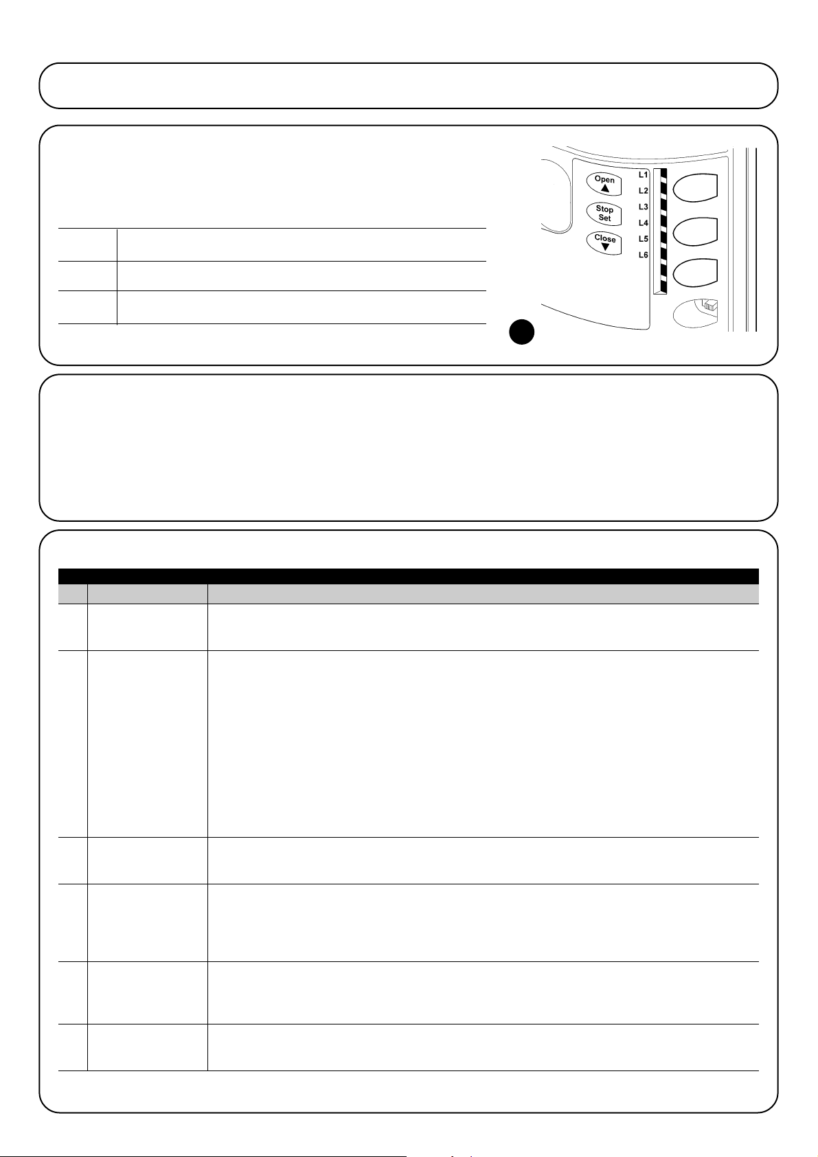
56
Led Fonction Description
L1 Fermetureautomatique
Cette fonction permet une fermeture automatique du portail après le temps de pause programmé; le Temps
de pause est réglé en usine à 30 secondes mais peut être modifié à 5, 15, 30, 45, 60 et 80 secondes. Si la
fonction n’est pas active, le fonctionnement est “semi-automatique”.
L2
Refermeture immédiate
Cette fonction permet de garder le portail ouvert uniquement le temps nécessaire au transit, en effet l'intervention de
après passage devant
“Photo” provoque toujours une refermeture automatique avec un temps de pause de 5 s (indépendamment de la
photocellule
valeur programmée) ; le comportement varie suivant si la “Fermeture Automatique” est active ou pas.
Si la “Fermeture automatique” n'est pas active : le portail atteint toujours la position d'ouverture totale (même si
la libération de la photocellule a lieu avant). La libération de la photocellule provoque une manœuvre de fermeture
automatique au bout de 5 s.
Avec la “fermeture automatique” active : la manœuvre d'ouverture s'arrête juste après que les photocellules
aient été libérées et 5 s plus tard la manœuvre de fermeture automatique commence.
La fonction “Refermeture immédiate après passage devant photocellule” est toujours désactivée dans les
manœuvres interrompues avec une commande de Stop.
Si la fonction “Refermeture immédiate après passage devant photocellule” n'est pas active, le temps de pause sera
celui qui est programmé ou bien il n'y aura pas de refermeture automatique si la fonction n'est pas active.
L3 Ferme toujours La fonction “Ferme toujours” intervient, provoquant une fermeture, quand au retour de l’alimentation la
logique détecte le portail ouvert. Pour des questions de sécurité la manœuvre est précédée par 5 s de
préclignotement. Si la fonction n’est pas active au retour de l’alimentation, le portail restera arrêté.
L4 Stand-By Cette fonction permet de réduire au maximum la consommation d’énergie, elle est utile en particulier
dans le fonctionnement avec batterie tampon. Si cette fonction est active, 1 minute après la fin de la
manœuvre, la logique éteint BLUEBUS (et donc les dispositifs) et toutes les led sauf la led BLUEBUS qui
clignotera plus lentement. Quand une commande arrive, la logique rétablit le plein fonctionnement. Si la
fonction n’est pas active, il n’y aura pas de réduction des consommations.
L5 Démarrage Avec l’activation de cette fonction, l’accélération progressive au début de chaque manœuvre est
désactivée; cela permet d’avoir la force de démarrage maximum et c’est utile en cas de frictions
statiques élevées, par exemple en cas de neige ou de givre qui bloquent le portail. Si la fonction n’est
pas active, la manœuvre commence avec une accélération progressive.
L6 Préclignotement Avec la fonction de préclignotement, une pause de 3 s est ajoutée entre l’allumage du clignotant et le
début de la manœuvre pour avertir l’utilisateur de la situation de danger. Si la fonction n’est pas active,
l’allumage du clignotant coïncide avec le début de la manœuvre.
Durant le fonctionnement normal de ROBUS350 les led L1…L6 sont allumées ou éteintes suivant l’état de la fonction à laquelle elles
correspondent, par exemple L1 est allumée si la “Fermeture automatique” est active.
Ce chapitre explique les possibilités de programmation et de personnalisation, ainsi que le diagnostic et la recherche des pannes sur
ROBUS350.
7) Approfondissements
Open La touche “OPEN” permet de commander l’ouverture du portail ou de
▲ déplacer vers le haut le point de programmation
Stop La touche “STOP” permet d’arrêter la manœuvre et si elle est pressée
Set plus de 5 secondes, elle permet d’entrer en programmation.
Close La touche “CLOSE” permet de commander la fermeture du portail
▼ ou de déplacer vers le bas le point de programmation.
7.1) Touches de programmation
Sur la logique de commande de ROBUS350 se trouvent 3 touches
qui peuvent être utilisées aussi bien pour la commande de la logique
durant les essais que pour les programmations:
7.2) Programmation
La logique de commande de ROBUS350 possède quelques fonctions programmables; le réglage des fonctions s’effectue à travers 3
touches présentes sur la logique: [▲] [Set] [▼] et sont visualisées
à l’aide de 6 led: L1…L6.
Les fonctions programmables disponibles sur ROBUS350 sont
réparties en deux niveaux:
Premier niveau: fonctions réglables en mode ON-OFF (actif ou
non actif); dans ce cas, chaque led L1...L6 indique une fonction, si
elle est allumée la fonction est active, si elle est éteinte la fonction
n’est pas active; voir tableau N°12.
Deuxième niveau: paramètres réglables sur une échelle de
valeurs (valeurs d’1 à 6); dans ce cas, chaque led L1…L6 indique la
valeur réglée parmi les 6 possibles; voir tableau N°14.
Tableau N°12: liste des fonctions programmables: premier niveau
7.2.1) Fonctions premier niveau (fonctions ON-OFF)
21
Page 57

F
57
Temps de
pause
Fonction P.P.
Vitesse
moteur
Sortie S.C.A.
Force moteur
Ouverture
partielle
L1
L2
L3
L4
L5
L6
L1
L2
L3
L4
L5
L6
L1
L2
L3
L4
L5
L6
L1
L2
L3
L4
L5
L6
L1
L2
L3
L4
L5
L6
L1
L2
L3
L4
L5
L6
5 secondes
15 secondes
30 secondes
45 secondes
60 secondes
80 secondes
Ouverture - stop - fermeture- stop
Ouverture - stop - fermeture- ouverture
Ouverture - fermeture- ouverture - fermeture
Fonctionnement collectif
Fermeture
Commande “homme mort”
Très lente
Lente
Moyenne
Rapide
Très rapide
Super rapide
Fonction S.C.A. (voyant portail ouvert)
Allumée si le portail est fermé
Allumée si le portail est ouvert
Active avec 2e commande radio
Active avec 3e commande radio
Active avec 4e commande radio
Portail “très léger”
Portail “léger”
Portail “moyen”
Portail “moyen-lourd”
Portail “lourd”
Portail “très lourd”
0,5 m
1 m
1,5 m
2 m
2,5 m
3 m
7.2.2) Programmation du premier niveau (fonctions ON-OFF)
En usine, les fonctions du premier niveau sont toutes mises sur “OFF” mais on peut les modifier à tout moment comme l’indique le tableau
N°13. Faire attention dans l’exécution de la procédure car il y a un temps maximum de 10 s entre la pression d’une touche et l’autre, autrement la procédure se termine automatiquement en mémorisant les modifications faites jusqu’à ce moment-là.
1. Presser et maintenir enfoncée la touche [Set] pendant environ 3 s
3s
2. Relâcher la touche [Set] quand la led L1 commence à clignoter
L1
3. Presser les touches [▲] ou [▼] pour déplacer la led clignotante sur la led qui correspond à la fonction
à modifier o
4. Presser la touche [Set] pour changer l’état de la fonction (clignotement bref = OFF; clignotement long = ON)
5. Attendre 10 s pour sortir de la programmation pour temps maximum écoulé.
10s
Note: les points 3 et 4 peuvent être répétées au cours de la même phase de programmation pour mettre d’autres fonctions en mode ON ou OFF
Tableau N°13: pour changer les fonctions ON-OFF Exemple
SET
SET
SET
7.2.3) Fonctions deuxième niveau (paramètres réglables)
Tableau N°14: liste des fonctions programmables: deuxième niveau
Led d’entrée Paramètre Led (niveau) valeur Description
Règle le temps de pause, c’est-à-dire le
temps avant la refermeture automatique.
La fonction n’a d’effet que si la fermeture
automatique est active
Règle la séquence de commandes associées à l’entrée P.P. ou bien à la première
commande radio (voir tableaux 4 et 5).
Règle la vitesse du moteur durant la course
normale.
Règle la fonction associée à la sortie
S.C.A.
Règle le système de contrôle de la force du
moteur pour l’adapter au poids du portail
Règle la mesure de l’ouverture partielle.
L’ouverture partielle peut se commander
uniquement avec la 2e commande radio
(voir tableaux 4 et 5)
Nota: “ ”représente le réglage fait en usine
L1
L2
L3
L4
L5
L6
Page 58

58
7.2.4) Programmation deuxième niveau (paramètres réglables)
En usine, les paramètres réglables sont réglés comme l’illustre le tableau avec: “ ” mais ils peuvent être modifiés à tout moment comme
l’indique le tableau N°15. Faire attention dans l’exécution de la procédure car il y a un temps maximum de 10 s entre la pression d’une touche
et l’autre, autrement la procédure se termine automatiquement en mémorisant les modifications faites jusqu’à ce moment-là.
1. Presser et maintenir enfoncée la touche [Set] pendant environ 3 s
3s
2. Relâcher la touche [Set] quand la led L1 commence à clignoter
L1
3. Presser les touches [▲] ou [▼] pour déplacer la led clignotante sur la “led d’entrée” qui correspond
au paramètre à modifier o
4. Presser et maintenir enfoncée la touche [Set], la pression doit être maintenue sur la touche [Set]
pendant toute la durée des phases 5 et 6
5. Attendre environ 3 s puis la led qui correspond au niveau actuel du paramètre à modifier s’allumera.
6. Presser les touches [▲] ou [▼] pour déplacer la led qui correspond à la valeur du paramètre.
o
7. Relâcher la touche [Set]
8. Attendre 10 s pour sortir de la programmation pour temps maximum écoulé.
10s
Note: les points de 3 à 7 peuvent être répétés au cours de la même phase de programmation pour régler plusieurs paramètres
Tableau N°15: pour modifier les paramètres réglables Exemple
SET
SET
SET
SET
7.2.5) Exemple de programmation premier niveau (fonctions ON-OFF)
Comme exemple nous indiquons les diverses opérations à effectuer pour modifier le réglage des fonctions fait en usine pour activer les fonctions de “Fermeture Automatique” (L1) et “Ferme toujours” (L3).).
1. Presser et maintenir enfoncée la touche [Set] pendant environ 3 s
3s
2. Relâcher la touche [Set] quand la led L1 commence à clignoter
L1
3. Presser une fois la touche [Set] pour changer l’état de la fonction associée à L1 (Fermeture Automatique),
maintenant la led L1 clignote avec clignotement long L1
4. Presser 2 fois la touche [▼] pour déplacer la led clignotante sur la led L3
L3
5. Presser une fois la touche [Set] pour changer l’état de la fonction associée à L3 (Ferme toujours),
maintenant la led L3 clignote avec clignotement long
6. Attendre 10 s pour sortir de la programmation pour temps maximum écoulé
10s
À la fin de ces opérations les led L1 et L3 doivent rester allumées pour indiquer que les fonctions de “Fermeture Automatique” et “Ferme
toujours” sont actives
Tableau N°16: exemple de programmation premier niveau Exemple
SET
SET
SET
SET
Tous les paramètres peuvent être réglés suivant les préférences sans
aucune contre-indication; seul le réglage “force moteur” pourrait
demander une attention particulière:
•Il est déconseillé d’utiliser des valeurs de force élevées pour com-
penser le fait que le portail a des points de friction anormaux. Une
force excessive peut compromettre le fonctionnement du système
de sécurité ou endommager le portail.
•Si le contrôle de la “force moteur” est utilisé comme soutien du système pour la réduction de la force d’impact, après chaque réglage,
répéter la mesure de la force, comme le prévoit la norme EN
12445.
• L’usure et les conditions atmosphériques peuvent influencer le
mouvement du portail, périodiquement il faut recontrôler le réglage
de la force.
Page 59
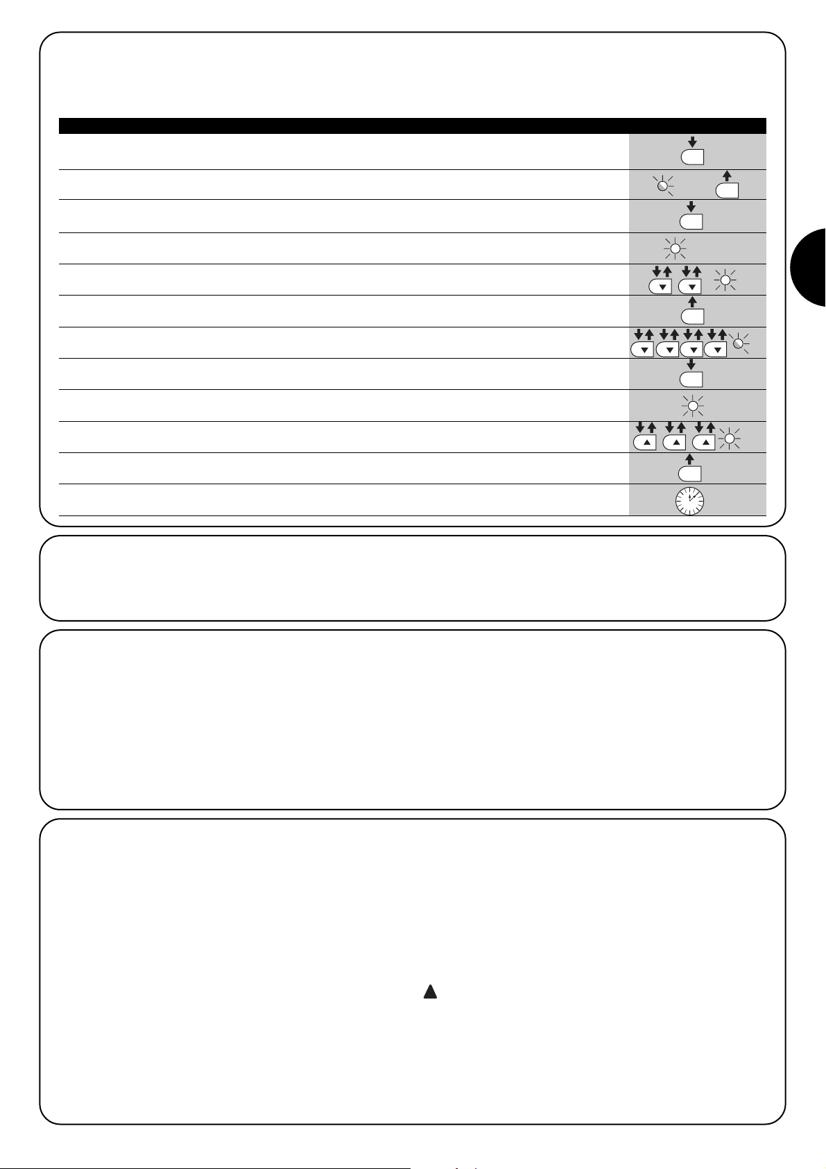
F
59
7.2.6) Exemple de programmation deuxième niveau (paramètres réglables)
Comme exemple nous indiquons les diverses opérations à effectuer pour modifier le réglage des paramètres effectué en usine en augmentant le “Temps de pause” à 60 s (entrée sur L1 et niveau sur L5) et en réduisant la “Force moteur” pour portails légers (entrée sur L5 et niveau
sur L2).
1. Presser et maintenir enfoncée la touche [Set] pendant environ 3 s
3s
2. Relâcher la touche [Set] quand la led L1 commence à clignoter
L1
3. Presser et maintenir enfoncée la touche [Set]; la pression sur la touche [Set] doit être maintenue
pendant toute la durée des phases 4 et 5
4. Attendre environ 3 s jusqu’à l’allumage de la led L3 qui correspond au niveau actuel du “Temps de pause”
L3 3s
5. Presser 2 fois la touche [▼] pour déplacer la led allumée sur L5 qui représente la nouvelle
valeur du “Temps de pause” L5
6. Relâcher la touche [Set]
7. Presser 4 fois la touche [▼] pour déplacer la led clignotante sur la led L5
L5
8. Presser et maintenir enfoncée la touche [Set]; la pression sur la touche [Set] doit être
maintenue pendant toute la durée des phases 9 et 10
9. Attendre environ 3 s jusqu’à l’allumage de la led L5 qui correspond au niveau actuel de la “Force moteur”
L3 3s
10. Presser 3 fois la touche [▲] pour déplacer la led allumée sur L2 qui correspond à la nouvelle
valeur de la “Force moteur” L2
11. Relâcher la touche [Set]
12. Attendre 10 s pour sortir de la programmation pour temps maximum écoulé
10s
Tableau N°17: exemple de programmation deuxième niveau Exemple
SET
SET
SET
SET
SET
SET
7.3) Ajout ou enlèvement de dispositifs
À un automatisme avec ROBUS350 on peut ajouter ou enlever des
dispositifs à n’importe quel moment. En particulier, à “BLUEBUS” et
à l’entrée “STOP” on peut connecter différents types de dispositifs
comme l’indiquent les paragraphes “7.3.1 BlueBUS” et “7.3.2
Entrée STOP”.
7.3.1) BlueBUS
BlueBUS est une technique qui permet d’effectuer les connexions
des dispositifs compatibles avec seulement deux conducteurs sur
lesquels transitent aussi bien l’alimentation électrique que les
signaux de communication. Tous les dispositifs sont connectés en
parallèle sur les 2 mêmes conducteurs de BlueBUS sans devoir respecter une polarité quelconque; chaque dispositif est reconnu individuellement car au cours de l’installation le système lui attribue une
adresse univoque. À BlueBUS, on peut connecter par exemple: des
photocellules, des dispositifs de sécurité, des boutons de comman
de, des voyants de signalisation, etc. La logique de commande de
ROBUS350 reconnaît un par un tous les dispositifs connectés à travers une procédure de reconnaissance ad hoc et est en mesure de
détecter de manière extrêmement sûre toutes les éventuelles anomalies. Pour cette raison, à chaque fois qu’on ajoute ou qu’on enlève un dispositif connecté à BlueBUS il faudra effectuer dans la
logique la procédure de reconnaissance décrite dans le paragraphe
“7.2.4 Reconnaissance d’autres dispositifs”.
7.3.2) Entrée STOP
STOP est l’entrée qui provoque l’arrêt immédiat de la manœuvre suivi d’une brève inversion. On peut connecter à cette entrée des dispositifs avec sortie à contact normalement ouvert “NO”, normalement fermé “NF” ou des dispositifs avec sortie à résistance constante 8,2kΩ, par exemple des barres palpeuses.
Comme pour BlueBUS, la logique reconnaît le type de dispositif
connecté à l’entrée STOP durant la phase de reconnaissance (voir
paragraphe “7.2.4 Reconnaissance d’autres dispositifs”); ensuite on
a un STOP quand une variation quelconque se vérifie par rapport à
l’état reconnu.
En adoptant certaines solutions on peut connecter à l’entrée STOP
plus d’un dispositif, même de type différent:
• Plusieurs dispositifs NO peuvent être connectés en parallèle entre
eux sans aucune limite de quantité.
• Plusieurs dispositifs NF peuvent être connectés en parallèle entre
eux sans aucune limite de quantité.
• Deux dispositifs avec sortie à résistance constante 8,2kΩ peuvent
être connectés en parallèle; s’il y a plus de 2 dispositifs, tous doivent être connectés en “cascade” avec une seule résistance terminale de 8,2kΩ.
• Il est possible de combiner NO et NF en mettant les deux contacts
en parallèle, en prenant la précaution de mettre en série au
contact NF une résistance de 8,2kΩ (cela donne aussi la possibilité de combiner 3 dispositifs: NO, NF et 8,2kΩ).
Si l’entrée STOP est utilisée pour connecter des dispositifs ayant des fonctions de sécurité, seuls les dispositifs
avec sortie à résistance constante 8,2kΩ garantissent la
catégorie 3 de sécurité aux pannes selon la norme EN
954-1.
!
Page 60

60
PHOTO
Photocellule extérieure h = 50
avec intervention en fermeture
PHOTO II
Photocellule extérieure h = 100
avec intervention en fermeture
PHOTO 1
Photocellule intérieure h = 50
avec intervention en fermeture
PHOTO 1 II
Photocellule intérieure h = 100
avec intervention en fermeture
PHOTO 2
Photocellule extérieure
avec intervention en ouverture
PHOTO 2 II
Photocellule intérieure
avec intervention en ouverture
PHOTO 3
Photocellule unique qui couvre tout
l’automatisme
l’installation de PHOTO 3 avec PHOTO II demande que la position des
éléments qui composent la photocellule (TX-RX) respecte la
recommandation donnée dans le manuel d’instructions des photocellules.
!
7.3.3) Photocellules
Le système “BlueBUS” permet, à travers l’adressage avec les cavaliers prévus à cet effet, la reconnaissance des photocellules de la
part de la logique et d’attribuer la fonction de détection correcte.
L’opération d’adressage doit être faite aussi bien sur TX que sur RX
(en plaçant les cavaliers de la même manière) en vérifiant qu’il n’y a
pas d’autres paires de photocellules ayant la même adresse. Dans
un automatisme pour portails coulissants équipé de l’opérateur
ROBUS350 il est possible d’installer les photocellules suivant les
indications de la figure 22. Après l’installation ou l’enlèvement de
photocellules, il faudra effectuer dans la logique la phase de reconnaissance comme le décrit le paragraphe “7.3.4 Reconnaissance
d’autres dispositifs”.
22
Tableau N°18: adresses des photocellules
Photocellule Cavaliers Photocellule Cavaliers
7.3.4) Reconnaissance d’autres dispositifs
Normalement la procédure de reconnaissance des dispositifs connectés à BlueBUS et à l’entrée STOP est effectuée durant la phase d’installation; toutefois si des dispositifs sont ajoutés ou enlevés, il est possible de refaire la reconnaissance en procédant de la manière suivante:
1. Presser et maintenir enfoncées les touches [▲] et [Set]
2. Relâcher les touches quand les led L1 et L2 commencent à clignoter très rapidement
(au bout d’environ 3 s) L1 L2
3. Attendre quelques secondes que la logique termine la reconnaissance des dispositifs
4. À la fin de la reconnaissance, les led L1 et L2 arrêteront de clignoter, la led STOP doit rester allumée,
tandis que les led L1…L6 s’allumeront suivant l’état des fonctions ON-OFF auxquelles elles correspondent. L1 L2
Après avoir ajouté ou enlevé des dispositifs, il faut effectuer de nouveau l’essai de l’automatisme suivant les indications
du paragraphe “5.1 Essai”.
!
Tableau N°19: pour la reconnaissance d’autres dispositifs Exemple
SET
SET
7.4.1) Fonction “Ouvre toujours”
La fonction “Ouvre toujours” est une propriété de la logique de commande qui permet de commander toujours une manœuvre d’ouverture quand la commande de “Pas à Pas” a une durée supérieure à
2 secondes; c’est utile par exemple pour connecter à la borne P.P.
le contact d’une horloge de programmation pour maintenir le portail
ouvert pendant une certaine plage horaire. Cette propriété est
valable quelle que soit la programmation de l’entrée P.P. à l’exclusion
de la programmation comme “Fermeture”, voir paramètre “Fonction
P.P.” dans le tableau N°14.
7.4.2) Fonction “Manœuvre dans tous les cas”
Si un dispositif de sécurité quelconque devait mal fonctionner ou
tomber en panne, il est possible dans tous les cas de commander
et de manœuvrer le portail en mode “Commande homme mort”.
Pour tout détail, voir le paragraphe “Commande avec sécurités hors
d’usage” présent dans les “Instructions et recommandations
destinées à l’utilisateur de l’opérateur ROBUS”ci-jointes.
7.4) Fonctions particulières
Page 61

F
61
7.6) Résolution des problèmes
Dans le tableau N°20 on peut trouver des indications utiles pour
affronter les éventuels problèmes de fonctionnement pouvant se
vérifier durant l’installation ou en cas de panne.
7.7) Diagnostic signalisations
Certains dispositifs offrent directement des signalisations particulières à travers lesquelles il est possible de reconnaître l’état de fonctionnement ou l’éventuel problème.
24
Tableau N°20: recherche des pannes
Symptômes Vérifications conseillées
L’émetteur radio ne commande pas le portail et
la led sur l’émetteur ne s’allume pas
L’émetteur radio commande pas le portail mais
la led sur l’émetteur s’allume
Aucune manœuvre n’est commandée et la led
“BLUEBUS” ne clignote pas
Aucune manœuvre n’est commandée et le clignotant est éteint.
Aucune manœuvre n’est commandée et le clignotant fait quelques clignotements
La manœuvre commence mais juste après on a
une inversion.
La manœuvre est effectuée régulièrement mais
le clignotant ne fonctionne pas
La manœuvre est effectuée régulièrement mais
le voyant SCA (portail ouvert) ne fonctionne pas.
Vérifier si les piles de l’émetteur sont usagées et les remplacer éventuellement.
Vérifier si l’émetteur est correctement mémorisé dans le récepteur radio
Vérifier que ROBUS350 est alimenté à la tension de secteur à 230V. Vérifier si les
fusibles sont grillés; si c’est le cas, identifier la cause de l’avarie et remplacer les
fusibles par d’autres ayant les mêmes valeurs de courant et caractéristiques.
Vérifier que la commande est effectivement reçue. Si la commande arrive à l’entrée PP
la led “PP” correspondante doit s’allumer; si par contre on utilise l’émetteur radio, la
led “Bluebus” doit faire deux clignotements rapides.
Compter le nombre de clignotements et vérifier suivant les indications du tableau N°21
La force sélectionnée pourrait être trop basse pour le type de portail. Vérifier s’il y a
des obstacles et sélectionner éventuellement une force supérieure.
Vérifier que durant la manœuvre la tension arrive à la borne FLASH du clignotant (comme il
est intermittent, la valeur de tension n’est pas significative: environ 10-30 Vcc); si la tension
arrive, le problème est dû à l’ampoule qui devra être remplacée par une autre de caractéristiques identiques; s’il n’y a pas de tension, il pourrait y avoir un problème de surcharge sur
la sortie FLASH, vérifier qu’il n’y a pas de court-circuit sur le câble.
Vérifier le type de fonction programmée pour la sortie SCA (Tableau N°14). Quand le voyant
devrait être allumé, vérifier que la tension arrive à la borne SCA (environ 24 Vcc); si la tension arrive, le problème est dû au voyant qui devra être remplacé par un autre de caractéristiques identiques; s’il n’y a pas de tension, il pourrait y avoir un problème de surcharge
sur la sortie SCA, vérifier qu’il n’y a pas de court-circuit sur le câble.
7.5) Connexion d’autres dispositifs
S’il est nécessaire d’alimenter des dispositifs extérieurs, par exemple un lecteur de proximité pour cartes transpondeur ou bien l’éclairage du sélecteur à clé, il est possible de prélever l’alimentation comme l’indique la figure 23.
La tension d’alimentation est de 24 Vcc -30% ÷ +50% avec courant
maximum disponible de 100 mA.
-+
24Vcc
23
F2
F1
Page 62
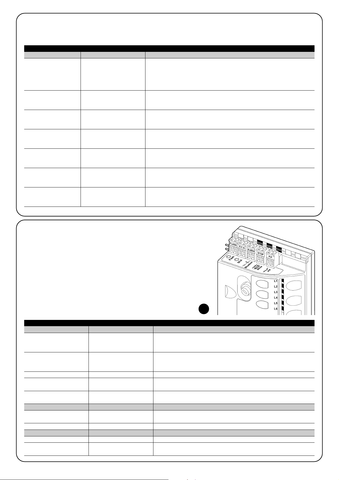
62
Led BLUEBUS Cause ACTION
Led STOP Cause ACTION
Led P.P. Cause ACTION
Éteinte
7.7.2) Signalisations sur la logique de commande
Dans la logique de ROBUS350 il y a une série de led qui peuvent
donner chacune des signalisations particulières aussi dans le fonctionnement normal qu’en cas d’anomalie.
Tableau N°22: led sur les bornes de la logique
Anomalie
Vérifier si l’alimentation arrive; vérifier si les fusibles sont intervenus; si c’est le
cas, vérifier la cause de la panne et remplacer les fusibles par d’autres ayant
les mêmes caractéristiques
Allumée Anomalie grave
Il y a une anomalie grave; essayer d’éteindre la logique pendant quelques
secondes; si l’état persiste, il y a une panne et il faut remplacer la carte électronique.
Un clignotement à la seconde Tout est OK Fonctionnement normal de la logique
2 clignotements rapides
Il y a eu une variation de l’état des entrées.
C’est normal quand il y a un changement de l’une des entrées: P.P., STOP,
intervention des photocellules ou quand on utilise l’émetteur radio
Série de clignotements séparés
par une pause d’une seconde
Diverses
C’est la même signalisation que celle du clignotant
Voir le Tableau N°21
Éteinte
Intervention de l’entrée de
STOP
Vérifier les dispositifs connectés à l’entrée de STOP
Allumée Tout est OK Entrée STOP active
Éteinte Tout est OK Entrée PP non active
Allumée
Intervention de l’entrée de
PP
C’est normal si le dispositif connecté à l’entrée PP est effectivement actif
25
6 clignotements
pause d’1 seconde
6 clignotements
Au début de la manœuvre, la vérification des dispositifs connectés à BLUEBUS ne correspond pas à ceux qui sont mémorisés durant la phase de
reconnaissance. Il peut y avoir des dispositifs en panne, vérifier et remplacer;
si des modifications on été faites, il faut refaire la reconnaissance (7.3.4
Reconnaissance d’autres dispositifs).
7.7.1) Signalisations avec le clignotant
Durant la manœuvre, l’indicateur clignotant FLASH émet un clignotement toutes les secondes; quand des anomalies se vérifient, les clignotements sont plus brefs; les clignotements se répètent deux fois, à intervalles d’une seconde.
Tableau N°21: signalisations sur le clignotant FLASH
Clignotements rapides Cause ACTION
1 clignotement
pause d’1 seconde
1 clignotemen
Erreur sur le BlueBUS
2 clignotements
pause d’1 seconde
2 clignotements
Intervention d’une photocellule
Au début de la manœuvre une ou plusieurs photocellules nie l’autorisation à
la manœuvre, vérifier si elles sont occultées par un obstacle. Durant le mouvement il est normal qu’un obstacle soit présent.
3 clignotements
pause d’1 seconde
3 clignotements
Intervention du limiteur de
la “Force moteur”
Durant le mouvement, le portail a rencontré une friction plus forte; en vérifier
la cause.
4 clignotements
pause d’1 seconde
4 clignotements
Intervention de l’entrée de
STOP
Au début de la manœuvre ou durant le mouvement, il y a eu une intervention
de l’entrée de STOP; en vérifier la cause
5 clignotements
pause d’1 seconde
5 clignotements
Erreur dans les paramètres
internes de la logique électronique.
Attendre au moins 30 secondes et réessayer de donner une commande; si
l’état persiste, il pourrait y avoir une panne grave et il faut remplacer la carte
électronique
La limite maximum du
nombre de manœuvres à
l’heure a été dépassée.
Attendre quelques minutes que le limiteur de manœuvres retourne sous la
limite maximum
7 clignotements
pause d’1 seconde
7 clignotements
Erreur dans les circuits
électriques internes
Déconnecter tous les circuits d’alimentation pendant quelques secondes puis
tenter de redonner une commande; si l’état persiste, il pourrait y avoir une
panne grave et il faut remplacer la carte électronique
Page 63

F
63
7.8) Accessoires
ROBUS350 peut être équipé des accessoires en option suivants:
• PS124 Batterie tampon 24 V - 1,2 Ah avec chargeur de batterie
incorporé
Consulter le catalogue des produits Nice S.p.a. pour la liste complète et à jour des accessoires.
26
Led 1 Description
• Programmation des fonctions en cours
• Si elle clignote en même temps que L4 cela signifie qu’il faut effectuer la reconnaissance de la longueur
du portail (voir paragraphe “4.4 Reconnaissance de la longueur du portail”).
Led L6 Description
Led L5 Description
Led L3 Description
Led L2 Description
Led L4
Description
Durant le fonctionnement normal elle indique fonction “Démarrage” non active.Éteinte
Éteinte
Tableau N°23: led sur les touches de la logique
Durant le fonctionnement normal elle indique fonction “Fermeture automatique” non active
Durant le fonctionnement normal elle indique fonction “Fermeture automatique” active
• Programmation des fonctions en cours
• Si elle clignote en même temps que L2 cela signifie qu’il faut effectuer la reconnaissance des dispositifs
(voir paragraphe “4.3 Reconnaissance des dispositifs”).
Allumée
Clignote
Éteinte
Durant le fonctionnement normal elle indique fonction “Refermeture immédiate près passage devant cellule” non active
Durant le fonctionnement normal elle indique fonction “Refermeture immédiate après passage devant
cellule” active
• Programmation des fonctions en cours
• Si elle clignote en même temps que L1 cela signifie qu’il faut effectuer la reconnaissance des dispositifs
(voir paragraphe “4.3 Reconnaissance des dispositifs”).
Allumée
Clignote
Éteinte Durant le fonctionnement normal elle indique fonction “Ferme toujours” non active
Durant le fonctionnement normal elle indique fonction “Ferme toujours” active
Durant le fonctionnement normal elle indique fonction “Stand-By” non active.
Durant le fonctionnement normal elle indique fonction “Stand-By” active.
• Programmation des fonctions en cours
• Si elle clignote en même temps que L3 cela signifie qu’il faut effectuer la reconnaissance de la longueur
du portail (voir paragraphe “4.4 Reconnaissance de la longueur du portail”).
Allumée
Clignote
Éteinte
Allumée
Clignote
Durant le fonctionnement normal elle indique fonction “Démarrage” active.
Programmation des fonctions en cours
Allumée
Clignote
Durant le fonctionnement normal elle indique fonction “Préclignotement” non active.
Durant le fonctionnement normal elle indique fonction “Préclignotement” active.
Programmation des fonctions en cours
Éteinte
Allumée
Clignote
27
Page 64

Puissance irradiée
Dimensions et poids
De 100 à 150 m, cette distance peut varier en présence d’obstacles et de parasites électromagnétiques
et elle est influencée par la position de l’antenne réceptrice
Utilisation en atmosphère particulièrement
acide ou saline ou potentiellement explosive
330 x 195 h 277; 8kg
Dans le but d’améliorer ses produits, Nice S.p.a. se réserve le droit de modifier les caractéristiques techniques à tout moment et sans préavis, en garantissant dans tous les cas le bon fonctionnement et le type d’utilisation prévus.
N.B.: toutes les caractéristiques techniques se réfèrent à la température de 20°C (±5°C)
8) Caractéristiques techniques
Typologie
Caractéristiques techniques: ROBUS350
Opérateur électromécanique pour le mouvement automatique de portails coulissants
pour usage résidentiel avec logique électronique de commande incorporée
Pignon Z: 15; Module: 4; Pas: 12,6 mm; Diamètre primitif: 60 mm
Couple maximum au démarrage
10 Nm; correspondant à la capacité de mettre en mouvement un portail avec friction statique jusqu’à 333 N
Couple nominal
6 Nm; correspond à la capacité de maintenir en mouvement un portail avec friction dyna-
mique jusqu’à 200 N
Vitesse au couple nominal
0,18m/s
Vitesse à vide (la logique permet de
programmer 6 vitesses égales à environ:
100, 85, 70, 55, 45, 30%)
0,34m/s
Fréquence maximum des cycles de fonctionnement
50 cycles/jour (la logique limite les cycles au maximum prévu dans les tableaux N°1 et N°2)
Temps maximum de fonctionnement continu
10 minutes (la logique limite le fonctionnement continu au maximum prévu dans les
tableaux N°1 et N°2)
Limites d’utilisation
Généralement ROBUS350 est en mesure d’automatiser des portails d’un poids allant jusqu’à 350 kg
ou d’une longueur allant jusqu’à 15 m et suivant les limites prévues dans les tableaux N°1 et N°2.
Puissance maximum absorbée 250VA
Classe d’isolement 1 (la mise à la terre est nécessaire)
Alimentation de secours Avec accessoire en option PS124
Sortie clignotant 1 clignotant LUCYB (Ampoule 12 V, 21W)
Sortie BLUEBUS Une sortie avec charge maximum de 15 unités BlueBus
Entrée STOP
Pour contacts normalement fermés, normalement ouverts ou à résistance constante 8,2kΩ; en
auto-apprentissage (une variation par rapport à l’état mémorisé provoque la commande “STOP”)
Entrée PP Pour contacts normalement ouverts (la fermeture du contact provoque la commande P.P.)
Entrée ANTENNE Radio 52 Ω pour câble type RG58 ou similaires
Alimentation ROBUS350
Alimentation ROBUS350/V1
230Vac (+10% +15%) 50/60Hz.
120Vac (+10% +15%) 50/60Hz.
Fonctions programmables 6 fonctions de type ON-OFF et 6 fonctions réglables (voir tableaux N° 12 et N° 14)
Température de fonctionnement -20°C ÷ 50°C
Non
Indice de protection IP 44
Dimensions et poids
Fonctions en auto-apprentissage
Auto-apprentissage des dispositifs connectés à la sortie BlueBUS Auto-apprentissage du
type de dispositif de “STOP”(contact NO, NF ou résistance 8,2kΩ) Auto-apprentissage
de la longueur du portail et calcul des points de ralentissement et ouverture partielle
Sorties 4 (sur connecteur SM)
Température de fonctionnement
-10°C ÷ 55°C
Typologie
Caractéristiques techniques
récepteur radio: SMXI récepteur radio: SMXIS
Récepteur à 4 canaux par radiocommande
Fréquence 433.92MHz
Codage Numérique Rolling code à 52 Bit, type FLOR Numérique Rolling code à 64 Bit, type SMILO
Compatibilité émetteurs
FLOR, VERY VR; seulement pour groupe
homogène: ERGO, PLANO, PLANOTIME
SMILO
Émetteurs mémorisables Jusqu’à 256 s’ils sont mémorisés en Mode I
Impédance d’entrée 52Ω
Sensibilité supérieure à 0,5 µV
Portée des émetteurs
72 x 40 h 18mm / 30g Diamètre 48 h 14 mm / 18 g
Indice de protection IP 40 (utilisation à l’intérieur ou dans des milieux protégés)
Température de fonctionnement
-40°C ÷ 85°C
Typologie Émetteur à 2 canaux par radiocommande
Fréquence 433.92MHz
Codage Numérique Rolling code à 52 Bit, type FLOR Numérique Rolling code à 64 Bit, type SMILO
Touches 2
Alimentation 12 Vcc avec pile type 23A
Absorption 25mA
Durée de la pile
1 an, estimée sur une base de 10 commandes/jour d’une durée d’1 s à 20°C (aux basses température
l’efficacité de la pile diminue)
100µW
Caractéristiques techniques
émetteur: FLO2R-S émetteur: SM2
64
Page 65

F
65
Félicitations pour avoir choisi un produit Nice pour
votre automatisation ! Nice S.p.A. produit des composants pour l’automatisme de portails, portes, rideaux
métalliques, volets roulants et stores: opérateurs,
logiques de commande, radiocommandes, clignotants, photocellules et accessoires. Nice n’utilise que
des matériaux et des usinages de qualité et par vocation, elle recherche des solutions innovantes qui simplifient au maximum l’utilisation de ses appareils, très
soignés sur le plan de la technique, de l’esthétique et
de l’ergonomie: dans la vaste gamme Nice, votre installateur aura choisi sans aucun doute le produit le plus
adapté à vos exigences. Nice n’est toutefois pas le
producteur de votre automatisme qui est en effet le
résultat d’un travail d’analyse, évaluation, choix des
matériaux et réalisation de l’installation, exécuté par
votre installateur de confiance. Chaque automatisme
est unique et seul votre installateur possède l’expérience et la compétence professionnelle nécessaires
pour réaliser une installation répondant à vos exigences, sûre et fiable dans le temps et surtout, exécutée dans les règles de l’art et conforme par conséquent aux normes en vigueur. Une installation d’automatisation est une belle commodité ainsi qu’un système de sécurité valable; avec quelques attentions très
simples, elle est destinée à durer dans le temps. Même
si l’automatisme en votre possession satisfait le niveau
de sécurité requis par les normes, cela n’exclut pas la
persistance d’un “risque résiduel”, c’est-à-dire la possibilité de situations de danger dues généralement à
une utilisation inconsciente, voire erronée. C’est la raison pour laquelle nous désirons vous donner quelques
conseils sur les comportements à adopter pour éviter
tout inconvénient:
•Avant d’utiliser pour la première fois l’automatisme, faites-vous expliquer par l’installateur l’origine
des risques résiduels et consacrez quelques minutes
à la lecture du manuel d’instructions et d’aver-
tissements pour l’utilisateur qui vous est remis
par l’installateur. Conservez le manuel pour pouvoir le
consulter pour n’importe quel doute futur et remettez-le à tout nouveau propriétaire de l’automatisme
•Votre automatisme est un équipement qui
exécute fidèlement vos commandes; une utilisation inconsciente et incorrecte peut le rendre dangereux: ne commandez pas le mouvement de l’automatisme si des personnes, des animaux ou des
objets se trouvent dans son rayon d’action.
•Enfants: une installation d’automatisation garantit
un degré de sécurité élevé en empêchant avec ses
systèmes de détection le mouvement en présence de
personnes ou d’objets et en garantissant une activation toujours prévisible et sûre. Il est prudent toutefois
d’éviter de laisser jouer les enfants à proximité de
l’automatisme et pour éviter les activations involontaires, de ne pas laisser à leur portée les émetteurs
qui commandent la manœuvre: ce n’est pas un
jeu!
•Anomalies: si vous notez une anomalie quelconque
dans le fonctionnement de l’automatisme, coupez
l’alimentation électrique de l’installation et procédez
au débrayage manuel. Ne tentez jamais de le réparer
vous-même mais demandez l’intervention de votre
installateur de confiance: dans l’intervalle, l’installation peut fonctionner comme un système non automatisé, après avoir débrayé l’opérateur suivant les
indications données plus loin.
•Maintenance: comme toutes les machines, votre
automatisme a besoin d’une maintenance périodique
pour pouvoir fonctionner le plus longtemps possible
et en toute sécurité. Établissez avec votre installateur
un plan de maintenance périodique programmée;
Nice conseille une intervention tous les 6 mois pour
une utilisation domestique normale mais celle période
peut varier en fonction de l’intensité d’utilisation. Toute intervention de contrôle, maintenance ou réparation doit être exécutée exclusivement par du personnel qualifié.
•Même si vous estimez en être capable, ne modifiez
pas l’installation et les paramètres de programmation
et de réglage de l’automatisme: la responsabilité en
incombe à votre installateur.
•L’essai de fonctionnement final, les maintenances
périodiques et les éventuelles réparations doivent
être documentés par la personne qui s’en charge et
les documents doivent être conservés par le propriétaire de l’installation.
Les seules interventions que l’utilisateur peut et
doit effectuer périodiquement sont le nettoyage des
verres des photocellules et l’élimination des feuilles et
des cailloux qui pourraient bloquer l’automatisme.
Pour empêcher que quelqu’un puisse actionner le portail, avant de continuer, n’oubliez pas de débrayer l’automatisme (comme nous l’avons décrit) et d’utiliser
pour le nettoyage uniquement un chiffon légèrement
imbibé d’eau.
•Mise au rebut. À la fin de la vie de l’automatisme,
assurez-vous que le démantèlement est effectué par
du personnel qualifié et que les matériaux sont recyclés ou mis au rebut en respectant les normes locales
en vigueur.
• En cas de ruptures ou absence d’alimenta-
tion électrique. En attendant l’intervention de votre
installateur (ou le retour du courant si l’installation est
dépourvue de batterie tampon), l’installation peut être
actionnée comme n’importe quel autre système non
automatisé. Pour cela, il faut effectuer le débrayage
manuel: cette opération, qui est la seule pouvant être
effectuée par l’utilisateur de l'automatisme), a fait
l’objet d’une étude particulière de la part de Nice
pour vous assurer toujours une utilisation extrêmement simple et aisée, sans aucun outil ou effort physique.
Instructions et recommandations destinées à l’utilisateur de l’opérateur ROBUS
Page 66
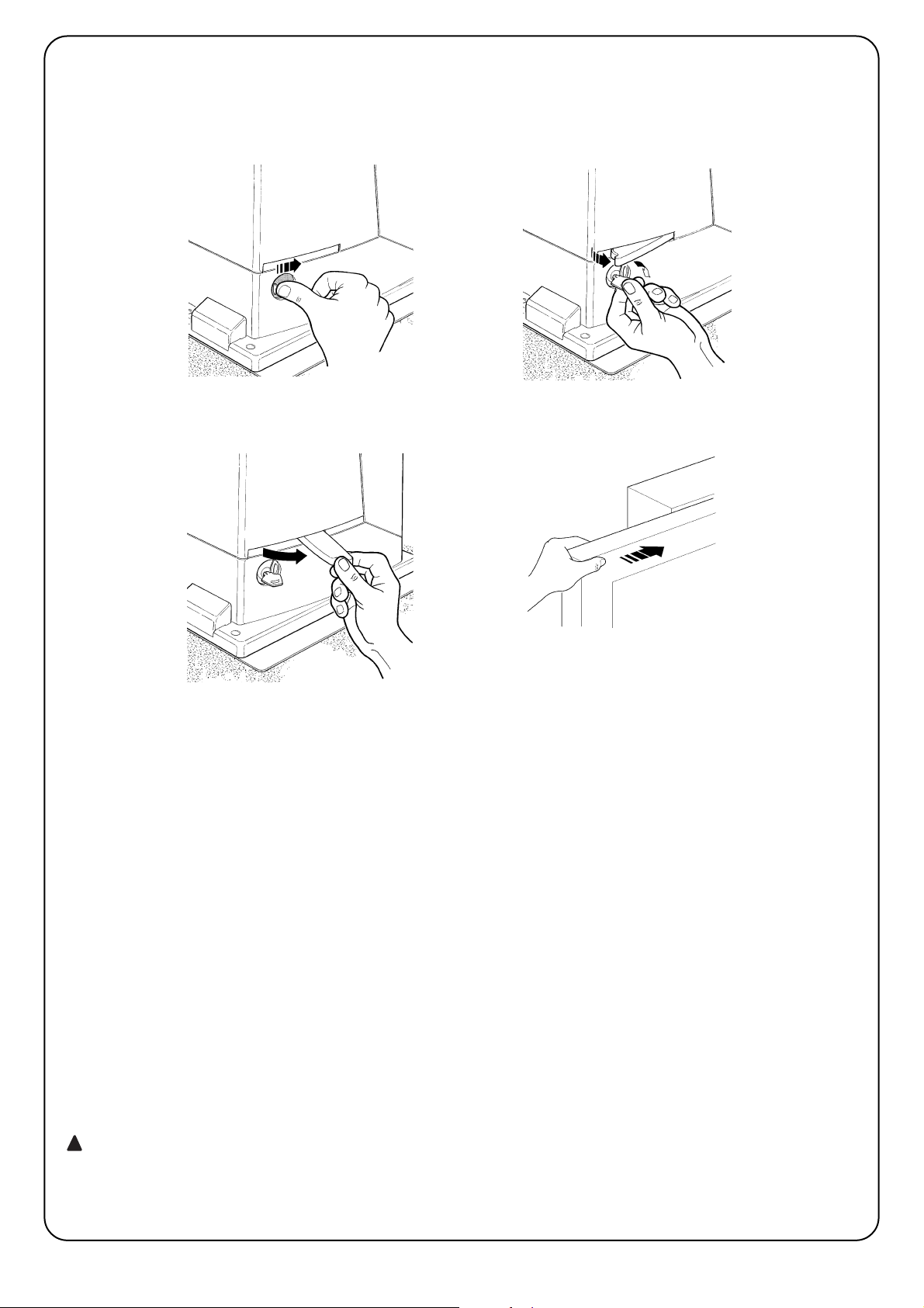
66
Débrayage et mouvement manuel: avant d’effectuer cette opération, faire attention au fait que le débrayage ne
peut être fait que lorsque le portail est à l’arrêt.
Pour bloquer: effectuer les mêmes opérations dans
le sens contraire
Commande avec sécurités hors service: Si les
dispositifs de sécurité ne fonctionnent pas correctement ou sont hors service, on peut quand même commander le portail
• Actionner la commande du portail (avec la télécommande ou le sélecteur à clé). Si les sécurités donnent leur accord le portail s’ouvrira normalement,
autrement: le clignotant émet quelques clignotements mais la manœuvre ne démarre pas (le nombre
de clignotements dépend du motif pour lequel la
manœuvre ne démarre pas).
• Maintenant, dans les 3 secondes, il faut actionner
de nouveau la commande et la maintenir active
• Au bout d’environ 2 s le mouvement du portail commencera en mode “homme mort”, c’est-à-dire que
tant que la commande est maintenue, le portail
continue sa manœuvre; dès que la commande est
relâchée, le portail s’arrête.
Avec les sécurités hors service, il faut faire
réparer au plus tôt l’automatisme.
Remplacement de la pile de l’émetteur: si votre
installation est munie d’une radiocommande qui au
bout d’une certaine période présente des problèmes
de fonctionnement ou ne fonctionne plus du tout, cela
pourrait dépendre tout simplement du fait que la pile
est usagée (suivant l’intensité d’utilisation, il peut
s’écouler plusieurs mois jusqu’à plus d’un an). Vous
pouvez vérifier cet état de chose si le voyant de confirmation de la transmission est faible, s’il ne s’allume
plus du tout ou s’il ne s’allume qu’un bref instant.
Avant de vous adresser à l’installateur, essayez de
remplacer la pile en utilisant celle d’un autre émetteur
qui fonctionne encore: si cette intervention remédie au
problème, il vous suffit de remplacer la pile usagée par
une neuve du même type.
Les piles contiennent des substances polluantes: ne
pas les jeter à la poubelle mais suivre les règles de tri
sélectif prévues par les réglementations locales.
Êtes-vous satisfait ? Si vous désirez équiper votre
maison d’un nouvel automatisme, adressez-vous au
même installateur et à Nice. Vous serez sûr de bénéficier ainsi, en plus du conseil d’un spécialiste et des
produits les plus évolués du marché, également du
meilleur fonctionnement et de la compatibilité parfaite
des différents automatismes installés.
Nous vous remercions d’avoir lu ces recommandations
et nous espérons que votre nouvelle installation vous
donnera entière satisfaction: pour tout besoin présent
ou futur, adressez-vous en toute confiance à votre installateur.
!
1 Faire coulisser le petit disque qui couvre
la serrure
2 Introduire la clé et la tourner dans le sens
des aiguilles d’une montre
3 Tirer la poignée de débrayage 4 Déplacer le portail à la main
Page 67

Page 68

68
7 Weitere Auskünfte 78
7.1 Programmierungstasten 78
7.2 Programmierungen 78
7.2.1 Funktionen des ersten Niveaus
(ON-OFF-Funktionen) 78
7.2.2 Erstes Niveau – Programmierungen
(ON-OFF-Funktionen) 79
7.2.3 Funktionen des zweiten Niveaus
(einstellbare Parameter) 79
7.2.4 Programmierung zweiten Niveaus
(einstellbare Parameter) 80
7.2.5 Erstes Niveau - Programmierungsbeispiel
(ON-OFF-Funktionen) 80
7.2.6 Zweites Niveau - Programmierungsbeispiel
(einstellbare Parameter) 81
7.3 Hinzufügen oder Entfernen von Vorrichtungen 81
7.3.1 BlueBUS 81
7.3.2 Eingang STOP 81
7.3.3 Photozellen 82
7.3.4 Erlernung sonstiger Vorrichtungen 82
7.4 Sonderfunktionen 82
7.4.1 Funktion “Öffnet Immer” 82
7.4.2 Funktion “Todmann” 82
7.5 Verbindung sonstiger Vorrichtunge 83
7.6 Probleme und deren Lösungen 83
7.7 Diagnose und Anzeigen 83
7.7.1 Anzeigen durch die Blinkleuchte 84
7.7.2 Anzeigen durch die Steuerun 84
7.8 Zubehör 85
8 Technische Merkmale 86
Anweisungen und Hinweise für den Benutzer
des Toröffners ROBUS 87
Inhaltsverzeichnis S.
1 Hinweise 69
2 Produktbeschreibung und Einsatz 69
2.1 Einsatzgrenzen 69
2.2 Typische Anlage 70
2.3 Kabelliste 70
3 Installation 70
3.1 Überprüfungen Vorbereitungen 71
3.2 Befestigung des Toröffners 71
3.3 Installation der verschiedenen Vorrichtungen 72
3.4 Elektrische Anschlüsse 72
3.5 Beschreibung der elektrischen Anschlüsse 73
4 Endprüfungen und Anlassen 73
4.1 Auswahl der Richtung 73
4.2 Anschluss der Versorgung 74
4.3 Erlernung der Vorrichtungen 74
4.4 Erlernung der Torlänge 74
4.5 Überprüfung der Torbewegung 74
4.6 Bereits programmierte Funktionen 74
4.7 Speicherung der Funksender 75
4.7.1 Speicherung, Modus I 75
4.7.2 Speicherung, Modus II 75
4.7.3 Fernspeicherung 76
4.7.4 Löschen der Funksender 76
4.7.5 Konformitätserklärung des Funkempfängers 76
5 Endprüfung und Inbetriebsetzung 76
5.1 Endprüfung 77
5.2 Inbetriebsetzung 77
6 Wartung und Entsorgung 77
6.1 Wartung 77
6.2 Entsorgung 77
Robus350
Page 69

D
69
2.1) Einsatzgrenzen
Die Leistungsdaten von ROBUS350 sind in Kapitel “8 Technische Merkmale” angegeben; sie ermöglichen als einzige Werte eine korrekte
Bewertung der Eignung von ROBUS350.
Gewöhnlich ist ROBUS350 imstande, Tore mit einem Gewicht bis zu 350
Kg oder einer Länge bis 15 m zu automatisieren, je nach den Angaben
in den Tabellen Nr. 1 und Nr. 2.
Aufgrund der Länge des Torflügels kann die Höchstzahl an Betriebszyklen pro Stunde und an aufeinanderfolgenden Zyklen bestimmt werden,
wogegen man mit dem Gewicht den Reduzierungsprozentsatz der
Zyklen und die zulässige Höchstgeschwindigkeit bestimmen kann; wenn
der Torflügel z.B. 5 m lang ist, wären 10 Zyklen/Stunde und 6 aufeinanderfolgende Zyklen möglich, wenn der Torflügel jedoch 240 kg wiegt,
müssen diese auf 80% reduziert werden, also 8 Zyklen/Stunde und ca.
5 aufeinanderfolgende Zyklen, wogegen die maximal zulässige
Geschwindigkeit V5 ist, also sehr schnell. Um Überhitzungen zu vermeiden, sieht die Steuerung einen Begrenzer vor, der sich auf der
Anstrengung des Motors und der Dauer der Zyklen beruht und bei Überschreitung der Höchstgrenze anspricht.
Torflügellänge in Metern max. Zyklen/Stunde
max. aufeinanderfolgende Zyklen
bis zu 3 30 20
3÷5 18 12
5÷6 15 10
6÷7 12 8
1) Hinweise
Die vorliegenden Anweisungen enthalten wichtige Sicherheitsinformationen für
die Installation; vor der Installation alle Anweisungen lesen und dieses Handbuch
auch für die Zukunft sorgfältig aufbewahren.
Unter Berücksichtigung der Gefahren, die bei Installation und Bedienung von
ROBUS350 auftreten können, muss die Installation für größte Sicherheit unter
voller Einhaltung von Gesetzen, Vorschriften und Verordnungen erfolgen. In diesem Kapitel sind Hinweise allgemeiner Art gegeben; weitere wichtige Hinweise
befinden sich in den Kapiteln “3.1 Vorprüfungen”; “5 Endprüfung und Inbetriebsetzung”.
Nach der neuesten europäischen Gesetzgebung, gehört die Realisierung einer automatischen Tür oder eines automatischen Tors zu
den Verordnungen der Richtlinie 98/37/CE (Maschinenrichtlinie) und
insbesondere zu den Vorschriften: EN 12445; EN 12453 und EN
12635, die es erlauben, die vermutliche Konformität zu erklären.
Weitere Auskünfte und Hinweise zur Analyse der Risiken und der Realisierung der
Technischen Unterlagen stehen in www.niceforyou.com zur Verfügung.
• Die vorliegende Anleitung ist nur für technisches Personal bestimmt, das für die
Installation qualifiziert ist. Mit Ausnahme der Anlage „Anweisungen und Hinweise für den Benutzer des Toröffners ROBUS“, die der Installateur abtrennen
muss, ist keine im vorliegenden Heft enthaltene Information als interessant für
den Endbenutzer zu betrachten!
• Ein Gebrauch von ROBUS350, der anders als in diesen Anweisungen vorge-
sehen ist, ist verboten; Ein unsachgemäßer Gebrauch kann Gefahren und Personen- oder Sachschäden verursachen.
• Vor der Installation ist die Risikoanalyse auszuführen, welche die Liste der
wesentlichen Sicherheitsanforderungen, vorgesehen in Anlage I der
Maschinenrichtlinie einschließen und die jeweiligen, angewendeten Lösungen angeben muss. Es wird daran erinnert, dass die Risikoanalyse einer der Unterlagen ist,
die Bestandteil der „Technischen Dokumentation“ der Automatisierung sind.
• Je nach Einsatzbedingungen und vorhandenen Gefahren prüfen, ob weitere
Vorrichtungen und Materialien erforderlich sind, um die Automatisierung mit
ROBUS350 zu vervollständigen; berücksichtigt werden müssen zum Beispiel
Aufprallgefahr, Quetsch- und Mitnehmgefahr usw. und sonstige Gefahren allgemein.
• Keine Änderungen an keinem Teil ausführen, falls nicht im vorliegenden Handbuch
vorgesehen. Vorgänge dieser Art können nur Betriebsstörungen verursachen.
NICE lehnt jegliche Haftung für Schäden aufgrund geänderter Produkte ab.
• Während Installation und Gebrauch vermeiden, dass Festteile oder Flüssigkeiten in die Steuerung und sonstige geöffnete Vorrichtungen eindringen können;
wenden Sie sich ggf. an den NICE Kundendienst; der Gebrauch von
ROBUS350 in solchen Situationen kann Gefahren verursachen.
•
Der Automatismus darf erst verwendet werden, nachdem die Inbetriebsetzung
ausgeführt wurde, wie in Punkt „5 Endprüfung und Inbetriebsetzung“ vorgesehen.
• Das Verpackungsmaterial von ROBUS350 muss unter voller Einhaltung der örtlichen Vorschriften entsorgt werden.
• Wenden ein Defekt mit den im vorliegenden Handbuch gegebenen Infos nicht
beseitigt werden kann, wenden Sie sich bitte an den NICE Kundendienst.
• Wenn Automatikschalter oder Sicherungen ausgelöst werden, muss vor ihrer
Rückstellung der Defekt festgestellt und beseitigt werden.
• Vor dem Zugriff auf die Klemmen im Deckel von ROBUS350, alle Kreisläufe der
Versorgung abtrennen; falls die Abtrennvorrichtung nicht sichtbar ist, ein Schild
mit der Aufschrift: “ACHTUNG – WARTUNG IM GANG” anbringen.
!
ROBUS350 ist ein elektromechanischer Toröffner für die automatische
Bewegung von Schiebetoren an Wohngebäuden; er verfügt über eine
elektronische Steuerung und einen Empfänger für Funksteuerungen. Die
elektrischen Verbindungen zu den externen Vorrichtungen sind dank der
Anwendung der “BlueBUS” Technik vereinfacht, mit der mehrere Vorrichtungen mit nur 2 Leitern angeschlossen werden können.
ROBUS350 funktioniert mit elektrischer Energie; bei Stromausfall
kann die Entriegelung mit einem speziellen Schlüssel ausgeführt
werden, so dass das Tor von Hand bewegt werden kann, oder man
kann das Sonderzubehör Pufferbatterie PS124 verwenden, mit dem
einige Bewegungen auch bei Netzstromausfall durchgeführt werden
können.
2) Produktbeschreibung und Einsatz
Tabelle Nr. 1: Grenzen in Abhängigkeit von der Torflügellänge
Torflügelgewicht kg. Prozentsatz an Zyklen
Zulässige Höchstgeschwindigkeit
Bis zu 200 100% V6 = Sehr sehr schnell
200÷250 90% V5 = Sehr schnell
250÷300 80% V4 = Schnell
300÷350 70% V3 = Mittel
Tabelle Nr. 2: Grenzen in Abhängigkeit vom Torflügelgewicht
1
330 195
85
277
Page 70

70
2.2) Typische Anlage
In Abbildung 2 ist die typische Anlage einer Schiebetorautomatisierung mit ROBUS350 gezeigt.
2
1 Schlüsseltaster
2 Photozellen auf Standsäule
3 Photozellen
4 Feste Hauptschaltleiste (Optional)
5 Bewegliche Hauptschaltleiste
6 Bügel des Endschalters “Geöffnet”
7 Blinkleuchte mit eingebauter Antenne
8 Feste Nebenschaltleiste (Optional)
9 Blinkleuchte mit eingebauter Antenne
10 ROBUS350
11 Bügel des Endschalters “Geschlossen”
12 Bewegliche Nebenschaltleiste
13 Funksender
2.3) Kabelliste
In der typischen Anlage in Abbildung 2 sind auch die Kabel angegeben, die zur Verbindung der verschiedenen Vorrichtungen erforderlich
sind; in Tabelle Nr. 3 sind die Merkmale der Kabel verzeichnet.
Die benutzten Kabel müssen für die jeweilige Installation geeignet sein; zum Beispiel wird ein Kabel des Typs H03VV-F zum
Verlegen in Innenräumen empfohlen, oder des Typs H07RN-F für Außenanwendungen.
!
Anmerkung 1: wenn das Versorgungskabel länger als 30 m ist, muss ein Kabel mit größerem Querschnitt benutzt werden, z.B. 3x2,5mm
2
und eine Sicherheitserdung in der Nähe der Automatisierung ist erforderlich.
Anmerkung 2: wenn das “BLUEBUS” Kabel länger als 30 m und bis zu max. 50m ist, muss ein Kabel 2x1mm
2
benutzt werden.
Anmerkung 3: die beiden Kabel 2x0,5mm
2
können mit nur einem Kabel 4x0,5mm2ersetzt werden.
Anmerkung 4: wenn mehr als eine Schaltleiste vorhanden ist, siehe das Kapitel “7.3.2 Eingang HALT” für die empfohlene Verbindung
Anmerkung 5: zur Verbindung der beweglichen Schaltleisten an Schiebetoren sind geeignete Vorrichtungen zu verwenden, welche die Ver-
bindung auch bei sich bewegendem Torflügel ermöglichen.
Verbindung Kabeltyp Zulässige Höchstlänge
A: Elektrische Versorgungsleitung Nr. 1 Kabel 3x1,5mm
2
30m (Anmerkung 1)
B: Blinkleuchte mit Antenne
Nr. 1 Kabel 2x0,5mm
2
20m
Nr. 1 Abschirmkabel des Typs RG58 20m (kürzer als 5m wird empfohlen)
C: Photozellen Nr. 1 Kabel 2x0,5mm
2
30m (Anmerkung 2)
D: Schlüsseltaster Nr. 2 Kabel 2x0,5mm2(Anmerkung 3) 50m
E: Feste Schaltleisten Nr. 1 Kabel 2x0,5mm2(Anmerkung 4) 30m
F: Bewegliche Schaltleisten Nr. 1 Kabel 2x0,5mm2(Anmerkung 4) 30m (Anmerkung 5)
Tabelle Nr. 3: Kabelliste
Die Installation von ROBUS350 muss von qualifiziertem Personal unter genauester Beachtung der Gesetze, Vorschriften
und Verordnungen und der Angaben in den vorliegenden Anweisungen ausgeführt werden.
!
3) Installation
2
43 38
10
2
6
11
7
9
13
1251
E
F
D
C F
A
B
Page 71

D
71
3.2) Befestigung des Toröffners
Falls die Befestigungsfläche bereits vorhanden ist, muss der Toröffner mit geeigneten Mittels wie z.B. Spreizdübel direkt auf der Oberfläche befestigt werden. Andernfalls, zur Befestigung des Toröffners:
1. Für das Fundament eine entsprechend große Grube ausgraben,
mit Bezugnahme auf die Maße in Abbildung 3.
2. Ein oder mehrere Rohre zum Durchführen der Stromkabel vorbereiten, gemäß Abbildung 4.
3. Die beiden Spreizbeine an die Fundamentplatte montieren; hierbei eine Mutter unter und eine über der Platte anbringen; die Mutter unter der Platte muss bis Gewindeende angeschraubt werden, so dass das Gewindeteil ca. 25÷35mm über der Platte her-
ausragt.
4.Den Beton eingießen und die Fundamentplatte bevor der Beton
hart wird, nach den Maßen in Abbildung 3 darin anbringen und
prüfen, dass sie parallel zum Torflügel und einwandfrei nivelliert
ist. Warten, bis der Beton ganz hart ist.
5. Die beiden Muttern über der Platte abschrauben, dann den
Toröffner darauf legen und prüfen, dass er zum Torflügel ganz
parallel ist, dann die beiden Muttern und die Unterlegscheiben
etwas anschrauben, wie in Abbildung 7 gezeigt.
3.1) Überprüfungen Vorbereitungen
Vor der Installation von ROBUS350 müssen folgende Kontrollen ausgeführt werden:
• Prüfen, dass das gesamte benutzte Material in bestem Zustand,
für den Einsatz geeignet und mit den Vorschriften konform ist.
• Prüfen, dass die Struktur des Tors so ist, dass es automatisiert
werden kann.
• Prüfen, dass sich Gewicht und Abmessungen des Torflügels innerhalb der Einsatzgrenzen in Kapitel “2.1 Einsatzgrenzen” befinden.
• Durch Vergleich mit den Werten in Kapitel “8 Technische Merkmale” prüfen, dass die statische Reibung (bzw. die zur Bewegung des
Torflügels notwendige Kraft) kleiner als die Hälfte des “maximalen
Drehmoments“ ist, und dass die dynamische Reibung (bzw. die
Kraft, die notwendig ist, um den Torflügel in Bewegung zu halten)
kleiner als die Hälfte des “Nenndrehmoments” ist; eine Spanne der
Kräfte von 50% wird empfohlen, da schlechte Witterung die Reibungswerte erhöhen kann.
• Prüfen, dass entlang dem gesamten Lauf des Tors sowohl in
Schließung als auch in Öffnung keine größeren Reibungen anliegen.
• Prüfen, dass der Torflügel nicht ausgleiten und nicht aus den
Führungen treten kann.
• Die Robustheit der mechanischen Überlaufanschläge kontrollieren
und prüfen, dass keine Verformungen erfolgen, auch wenn der
Torflügel heftig auf diese aufprallen sollte.
• Prüfen, dass der Torflügel im Gleichgewicht ist: er darf sich nicht
bewegen, wenn er in beliebiger Stellung stehen bleibt.
• Prüfen, dass sich der Bereich, in dem der Toröffner befestigt wird,
nicht überschwemmen kann; den Toröffner ggf. über dem Boden
installieren.
• Prüfen, dass die Entriegelung und eine leichte und sichere Bewegung von Hand des Torflügels im Befestigungsbereich des Toröffners möglich sind.
• Prüfen, ob sich die Befestigungsstellen der verschiedenen Vorrichtungen in stoßgeschützten Bereichen befinden und ob die Oberflächen ausreichend solide sind.
• Elemente des Automatismus sollten nicht in Wasser oder andere
Flüssigkeit getaucht werden.
• ROBUS350 nicht in der Nähe von Wärmequellen oder Flammen
oder in EX-gefährdeter, salz- oder säurehaltiger Umgebung halten;
dies kann Schäden und Betriebsstörungen an ROBUS350 sowie
Gefahren verursachen.
• Sollte der Torflügel eine Eingangstür haben oder sich eine Tür im
Bewegungsbereich des Torflügels befindet, ist sicher zu stellen,
dass diese den normalen Lauf des Tors nicht behindert; ggf. für ein
geeignetes Verblockungssystem sorgen.
• Die Steuerung an eine elektrische Versorgungsleitung mit Sicherheitserdung anschließen.
• Die elektrische Versorgungsleitung muss durch eine geeignete
magnetothermische Differentialvorrichtung geschützt sein.
• In die Versorgungsleitung vom Stromnetz muss eine Abtrennvorrichtung der Versorgung eingeschaltet werden (mit Überspannungsklasse III bzw. mindestens 3,5 mm Abstand zwischen den
Kontakten), oder ein anderes gleichwertiges System, zum Beispiel
eine Steckdose mit jeweiligem Stecker. Falls sich die Abtrennvorrichtung nicht in der Nähe der Automatisierung befindet, muss ein
Sperrsystem gegen nicht beabsichtigten und nicht genehmigten
Anschluss vorgesehen werden. contro la connessione non intenzionale o non autorizzata.
3
4
5
6
192
330 0÷50
0÷50 330
192
0÷10
0÷10
25÷35
7
Page 72

72
3.3) Installation der verschiedenen Vorrichtungen
Die Installation der anderen vorgesehenen Vorrichtungen nach den jeweiligen Anweisungen ausführen. In Punkt “3.5 Beschreibung der elektrischen Anschlüsse” und in Abbildung 2 die Vorrichtungen überprüfen, die an ROBUS350 angeschlossen werden können.
Um zu vermeiden, dass das Gewicht des Torflügels auf
dem Toröffner liegt, muss zwischen Zahnstange und Ritzel
ein Spiel von 1÷2 mm vorhanden sein, wie in Abbildung
10.
8. Den Torflügel gleiten lassen und zur Befestigung der anderen
Zahnstangenteile immer Bezug auf das Ritzel nehmen.
9. Das überschüssige Teil am Ende der Zahnstange wegschneiden.
10. Versuchen, den Torflügel mehrmals in Öffnung zu bewegen,
dabei prüfen, dass die Zahnstange mit einer maximalen Nichtfluchtung von 5 mm gut ausgerichtet auf dem Ritzel gleitet und
dass in der gesamten Länge das Spiel von 1÷2 mm zwischen
Ritzel und Zahnstange vorhanden ist.
11.Die Befestigungsmuttern des Toröffners energisch anziehen, so
dass dieser gut am Boden befestigt ist; die Befestigungsmuttern
mit den dazu vorgesehenen Kappen bedecken, gemäß Abbildung 11.
12.Die Endschalterbügel “Öffnung” und “Schließung” mit den jeweiligen Stiftschrauben an den Außenseiten der Zahnstange befestigen, wie in Abbildung 12. Berücksichtigen, dass der Torflügel
bei Auslösung der Endschalter noch ca.2-3cm weitergleiten
wird, daher die Endschalterbügel etwas von den mechanischen
Endanschlägen entfernt anbringen.
13.Den Toröffner wie in Punkt “Entriegelung und Bewegung von
Hand” im Kapitel “Anweisungen und Hinweise für den Benutzer
des Toröffners ROBUS” angegeben blockieren.
!
8 9
10
11 12
Falls die Zahnstange bereits vorhanden ist, nach der Befestigung
des Toröffners die Verstellstifte betätigen, wie in Abbildung 8gezeigt,
um das Ritzel von ROBUS350 auf die richtige Höhe zu bringen und
1÷2 mm Spiel von der Zahnstange zu lassen.
Andernfalls, für die Befestigung der Zahnstange wie folgt vorgehen:
6. Den Toröffner entriegeln, wie in “Entriegelung und Bewegung von
Hand” im Kapitel “Anweisungen und Hinweise für den Benutzer
des Toröffners ROBUS” angegeben.
7. Den Torflügel ganz öffnen, das erste Teil der Zahnstange auf das
Ritzel legen und prüfen, dass der Anfang der Zahnstange mit
dem Anfang des Torflügels übereinstimmt, gemäß Abbildung 9.
Prüfen, dass ein Spiel von 1÷2 mm zwischen Ritzel und Zahnstange vorhanden ist, dann die Zahnstange mit geeigneten Mitteln am Torflügel befestigen.
1÷2
3.4) Elektrische Anschlüsse
Alle elektrischen Anschlüsse müssen ohne Spannung
zur Anlage und mit abgetrennter, eventueller Pufferbatterie ausgeführt werden.
1. Um den Schutzdeckel zus entfernen und Zugang zur elektronischen
Steuerung von ROBUS350 zu erhalten, muss die Schraube seitlich
entfernt und der Deckel nach oben herausgezogen werden.
2. Die Gummimembrane entfernen, mit der das Loch für den Kabel-
durchgang geschlossen ist, und alle Verbindungskabel zu den
verschiedenen Vorrichtungen einführen, dabei die Kabel 20÷30
cm länger als notwendig lassen. Siehe die Tabelle Nr. 3 für den
Kabeltyp und die Abbildung 1 für die Anschlüsse.
3. Alle Kabel, die in den Toröffner eintreten, mit einer Schelle verei-
nen. Die Schelle gleich unter dem Loch für den Kabeldurchgang
anbringen. An der Gummimembrane ein Loch schneiden, dessen
Durchmesser etwas kleiner als der Durchmesser der vereinten
Kabel ist, dann die Membrane entlang den Kabeln bis zur Schelle einstecken und die Membrane wieder in ihren Sitz am Loch des
Kabeldurchgangs einspannen. Die Kabel gleich über der Membrane mit einer zweiten Schelle vereinen.
4. Das Versorgungskabel an der jeweiligen Klemme anschließen,
wie in Abbildung 13 gezeigt, dann das Kabel am ersten Kabelhaltering mit einer Schelle blockieren.
5. Die Anschlüsse der anderen Kabel nach dem Plan in Abbildung
15 ausführen. Der Einfachheit wegen können die Klemmen abgezogen werden.
6. Die vereinten Kabel nach Beendigung der Anschlüsse mit Schellen am zweiten Kabelhaltering blockieren; das überschüssige Teil
des Antennekabels muss mit einer weiteren Schelle an den anderen Kabeln blockiert werden, gemäß Abbildung 14.
!
Page 73
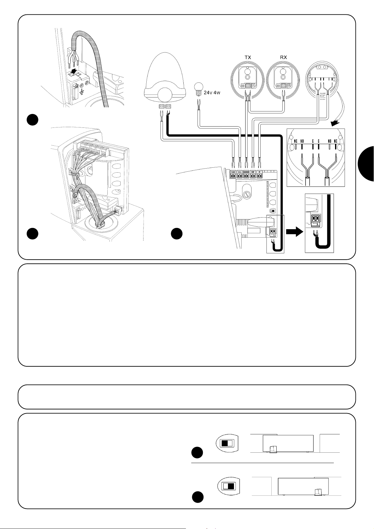
D
73
3.5) Beschreibung der elektrischen Anschlüsse
Dieser Paragraph enthält eine kurze Beschreibung der elektrischen
Anschlüsse; für weitere Auskünfte wird auf Punkt o “7.3 Hinzufügen
oder Entfernen von Vorrichtungen” verwiesen.
FLASH: Ausgang für Blinkleuchte des Typs “LUCYB” oder ähnliche
nur mit 12 V Lampe, max. 21W.
S.C.A.: Ausgang für “Kontrolllampe Tor Geöffnet”; es kann eine 24
V Kontrolllampe max. 4 W angeschlossen werden
BLUEBUS: an dieser Klemme können kompatible Vorrichtungen
angeschlossen werden; alle Vorrichtungen werden mit nur zwei Leiters für die Stromversorgung und die Kommunikationssignale parallel geschaltet. Weitere Auskünfte über BlueBUS sind in Punkt “7.3.1
BlueBUS” enthalten.
STOP: Eingang für Vorrichtungen, welche die laufende Bewegung
blockieren oder ggf. anhalten; mit entsprechenden Maßnahmen am
Eingang können „gewöhnlich geschlossene“ und „gewöhnlich geöffnete“ Kontakte oder Vorrichtungen mit gleichbleibendem Widerstand angeschlossen werden. Weitere Auskünfte über STOP sind in
Punkt “7.3.2 Eingang STOP” enthalten.
P.P.(Schrittbetrieb): Eingang für Vorrichtungen, welche die Bewegung steuern; es können „gewöhnlich geöffnete“ Kontakte angeschlossen werden.
ANTENNA: Eingang für den Anschluss der Antenne für den Funkempfänger (die Antenne ist in LUCY B eingebaut).
13
14
15
Vor Beginn der Überprüfung und des Anlassens der Automatisierung sollte das Tor auf Laufhälfte verschoben werden, so dass es sich in Öffnung und Schließung frei bewegen kann.
4) Endprüfungen und Anlassen
4.1) Auswahl der Richtung
Je nachdem, wie der Toröffner am Torflügel angebracht ist, muss die
Richtung der Öffnungsbewegung gewählt werden. Falls sich der
Torflügel zum Öffnen nach links bewegen muss, den Wählschalter
nach links verschieben, wie in Abbildung 16, falls er sich zum Öffnen
nach rechts bewegen muss, den Wählschalter nach rechts verschieben, wie in Abbildung 17.
16
17
LUCYB S.C.A. MOFB MOSE
Page 74

74
Sobald ROBUS350 mit Spannung versorgt ist, sollten einige einfache Überprüfungen ausgeführt werden:
1. Prüfen, ob die LED BLUEBUS regelmäßig einmal pro Sekunde
blinkt.
2. Prüfen, ob auch die LEDs an den Photozellen blinken (an TX und
an RX); wie die LEDs blinken, ist unwichtig und auf andere Ursachen zurückzuführen.
3. Prüfen, ob die am Ausgang FLASH angeschlossene Blinkleuchte
und die am Ausgang S.C.A. angeschlossene Kontrolllampe
ausgeschaltet sind.
Falls nicht alles obige erfolgt, die Versorgung zur Steuerung unverzüglich abschalten und die elektrischen Anschlüsse genauer überprüfen.
Weitere nützliche Hinweise für die Suche und Diagnose der Defekte
finden Sie auch in Kapitel “7.6. Probleme und deren Lösungen”
4.2) Anschluss der Versorgung
der Anschluss der Versorgung zum ROBUS350 muss von erfahrenem Fachpersonal mit den erforderlichen Kenntnis-
sen und unter voller Einhaltung von Gesetzen, Vorschriften und Verordnungen ausgeführt werden.
!
4.3) Erlernung der Vorrichtungen
Nach dem Anschluss der Versorgung muss die Steuerung die Vorrichtungen erlernen, die an den Eingängen BLUEBUS und STOP
angeschlossen sind. Vor dieser Phase blinken die LEDs L1 und L2
und geben somit an, dass die Erlernung der Vorrichtungen ausgeführt werden muss.
1. Auf die Tasten [▲] und [Set] drücken und gedrückt halten
2. Die Tasten loslassen, wenn die LEDs L1 und L2 sehr schnell zu blinken beginnen (nach ca. 3s)
3. Ein paar Sekunden warten, bis die Steuerung die Erlernung der Vorrichtungen beendet
4. 8. Am Ende der Erlernung muss die LED STOP eingeschaltet bleiben, wogegen die LEDs L1 und L2 erlöschen
werden (eventuell werden die LEDs L3 und L4 zu blinken beginnen.
4.4) Erlernung der Torlänge
Nach der Erlernung der Vorrichtungen werden die LEDs L3 und L4
zu blinken beginnen. Das bedeutet, dass die Steuerung die Länge
des Torflügels erkennen muss (Abstand zwischen Endschalter in
Schließung und Endschalter in Öffnung). Dieses Maß ist für die
Berechnung der Stellen notwendig, an denen die Verlangsamung
und die Teilöffnung erfolgen soll.
Falls nicht alles obige erfolgt, die Versorgung zur Steuerung unverzüglich abschalten und die elektrischen
Anschlüsse genauer überprüfen. Weitere nützliche Hinweise finden Sie auch in Kapitel “7.6 Probleme und
deren Lösungen”.
1. Auf die Tasten [▼] und [Set] drücken und gedrückt halten
2. Die Tasten loslassen, wenn die Bewegung beginnt (nach ca. 3 s)
3. Prüfen, dass die laufende Bewegung eine Öffnungsbewegung ist, andernfalls auf Taste [Stop] drücken und
Punkt “4.1 Auswahl der Richtung” genauer kontrollieren; dann ab Punkt 1 wiederholen.
4. Warten, bis die Steuerung die Öffnungsbewegung bis zum Endschalter in Öffnung durchgeführt hat; gleich
danach beginnt die Schließbewegung.
5. Warten, bis die Steuerung die Schließbewegung durchgeführt hat.
4.5) Überprüfung der Torbewegung
Nach der Erlernung der Torflügellänge sollten einige Bewegungen ausgeführt werden, um zu prüfen, ob die Torbewegung korrekt ist.
1.Auf Taste [Open] drücken, um den Befehl für die Bewegung “Öffnet”
zu erteilen; prüfen, ob die Toröffnung regelmäßig und ohne Geschwindigkeitsschwankungen erfolgt; erst wenn sich der Torflügel zwischen
70 und 50 cm vom Endschalter in Öffnung befindet, muss es verlangsamen und aufgrund der Auslösung des Endschalters 2÷3 cm
vom mechanischen Endanschlag in Öffnung entfernt anhalten.
2.Auf Taste [Close] drücken, um den Befehl für die Bewegung
“Schließt” zu erteilen; prüfen, ob die Torschließung regelmäßig und
ohne Geschwindigkeitsschwankungen erfolgt; erst wenn sich der
Torflügel zwischen 70 und 50 cm vom Endschalter in Schließung
befindet, muss es verlangsamen und aufgrund der Auslösung des
Endschalters 2÷3 cm vom mechanischen Endanschlag in Schließung
entfernt anhalten.
3.Während der Bewegungen prüfen, dass die Blinkleuchte das Blinken
intermittierend alle 0,5 s ausführt (0,5 s ein und 0,5 s aus). Falls vorhanden, auch das Blinken der an Klemme SCA angeschlossenen
Kontrolllampe kontrollieren: langsames Blinken iN Öffnung und schnell
in Schließung.
4.Verschiedene Öffnungs- und Schließbewegungen ausführen, um
eventuelle Montage- und Einstellfehler oder andere Störungen wie
zum Beispiel Stellen mit stärkerer Reibung aufzufinden.
5.Prüfen, dass die Befestigung des Toröffners ROBUS350, der Zahnstange und der Endschalterbügel auch nach plötzlichen Beschleunigungen oder Verlangsamungen der Torbewegung solide, stabil und
genügend widerstandsfähig ist.
4.6) Bereits programmierte Funktionen
Die Steuerung von ROBUS350 verfügt über einige programmierbare
Funktionen. Werkseitig sind diese Funktionen so konfiguriert, dass
sie den Bedarf der meisten Automatisierungen zufrieden stellen
müssten; sie können aber über ein entsprechendes Programmierungsverfahren jederzeit geändert werden – siehe hierzu Punkt “7.2
Programmierungen”.
18
19
Die Erlernung der angeschlossenen Vorrichtungen kann jederzeit auch nach der Installation wiederholt werden,
wenn zum Beispiel eine Vorrichtung hinzugefügt wird. Um eine neue Erlernung auszuführen, siehe Punkt “7.3.4
Erlernung sonstiger Vorrichtungen”
Page 75

D
75
N°1 Befehl “Schrittbetrieb”
N°2 Befehl “Gehflügelöffnung”
N°3 Befehl “Öffnet”
N°4 Befehl “Schließt”
Tabelle Nr. 5: im Modus II zur Verfügung stehende Befehle
4.7) Speicherung der Funksender
Für die Fernsteuerung von ROBUS350 ist an der Steuerung der Steckverbinder SM für Funkempfänger des Typs SMXI oder SMXIS vorgesehen (siehe Abb. 20); jeder Funksender wird vom diesem Empfänger durch einen „Code“ erkannt, der anders als der Code jedes anderen
Senders ist. Daher ist eine „Speicherungsphase“ notwendig, in der man den Empfänger darauf vorbereitet, jeden einzelnen Sender zu erkennen. Die Speicherung der Sender kann auf zwei verschiedene Arten erfolgen:
Modus I: Bei dieser Speicherart ist die Funktion der Sendertasten
fest und jeder Taste entspricht in der Steuerung der in Tabelle Nr. 4
angegebene Befehl. Für jeden Sender führt man nur eine Speicherphase aus, bei der alle Tasten gespeichert werden. In dieser Phase ist
es unwichtig ist, welche Taste man drückt, und es wird nur ein Speicherplatz belegt. Im Modus I kann ein Sender gewöhnlich nur eine
Automatisierung steuern. Tabelle Nr. 4: Speicherung im Modus I.
Modus II: in diesem Modus kann jeder einzelnen Sendertaste einer
der vier möglichen Befehle der Steuerung, angegeben in Tabelle Nr.
5 zugeteilt werden; in jeder Phase wird nur eine Taste gespeichert,
genauer gesagt jene, die während der Speicherphase gedrückt wird.
Im Speicher wird für jede gespeicherte Taste ein Platz belegt.
Im Modus II können die verschiedenen Tasten desselben Senders
benutzt werden, um derselben Automatisierung mehrere Befehle zu
erteilen oder um mehrere Automatisierungen zu steuern. Zum Beispiel wird in Tabelle Nr. 6 nur die Automatisierung “A” gesteuert und
die Tasten T3 und T4 sind demselben Befehl zugeteilt, oder im Beispiel in Tabelle 7 werden drei Automatisierungen gesteuert: “A”
(Tasten T1 und T2), “B” (Taste T3) und “C” (Taste T4).
Da die Speicherverfahren eine Zeitgrenze von 10 s
haben, die Anweisungen in den nächsten Punkten vor den
Speicherungen lesen und die letzteren erst danach ausführen.
!
Taste T1 Befehl “Schrittbetrieb”
Taste T2 Befehl “Gehflügelöffnung”
Taste T3 Befehl “Öffnet”
Taste T4 Befehl “Schließt”
Tabelle Nr. 4: Speicherung im Modus I
Taste T1 Befehl “Öffnet” Automatisierung A
Taste T2 Befehl “Schließt”” Automatisierung A
Taste T3 Befehl “Gehflügelöffnung” Automatisierung A
Taste T4 Befehl “Gehflügelöffnung” Automatisierung A
Tabelle Nr. 6: 1. Speicherbeispiel im Modus II
Taste T1 Befehl “Öffnet” Automatisierung A
Taste T2 Befehl “Schließt” Automatisierung A
Taste T3 Befehl “Schrittbetrieb” Automatisierung B
Taste T4 Befehl “Schrittbetrieb” Automatisierung C
Tabelle Nr. 7: 2. Speicherbeispiel im Modus II
Anmerkung: die einkanaligen Sender verfügen nur über die Taste T1, die
zweikanaligen Sender verfügen nur über die Tasten T1 und T2.
1. Auf die kleine Taste am Empfänger drücken und gedrückt halten (ca. 3 s lang)
3s
2. Die Taste loslassen, wenn die LED am Empfänger aufleuchtet
3. Innerhalb von 10 s mindestens 2 s auf eine beliebige Taste des zu speichernden Funksenders drücken
2s
4. Die LED am Empfänger wird 3 Mal blinken, falls die Speicherung erfolgreich war
x3
Zur Speicherung weiterer Sender, Schritt 3 innerhalb weiterer 10 s wiederholen. Die Speicherphase wird automatisch beendet, falls
innerhalb von 10 s keine neuen Codes erhalten werden.
Tabelle Nr. 8: zum Speichern eines Senders im Modus I Beispiel
4.7.1) Speicherung, Modus I
1. Auf die kleine Taste am Empfänger sooft drücken, wie der gewünschte
Steuerbefehl ist – siehe Tabelle Nr. 5 1....4
2. Prüfen, ob die LED am Empfänger sooft blinkt, wie der gewählte Steuerbefehl ist.
1....4
3. Innerhalb von 10s mindestens 2s auf die gewünschte Taste des zu speichernden Funksenders drücken
2s
4. Die LED am Empfänger wird 3 Mal blinken, falls die Speicherung erfolgreich war.
x3
Zur Speicherung weiterer Sender für den gleichen Steuerbefehl, Schritt 3 innerhalb weiterer 10s wiederholen. Die Speicherphase wird
automatisch beendet, falls innerhalb von 10s keine neuen Codes erhalten werden.
Tabelle Nr. 9: zum Speichern der Taste eines Senders im Modus II Beispiel
4.7.2) Speicherung, Modus II
20
Page 76
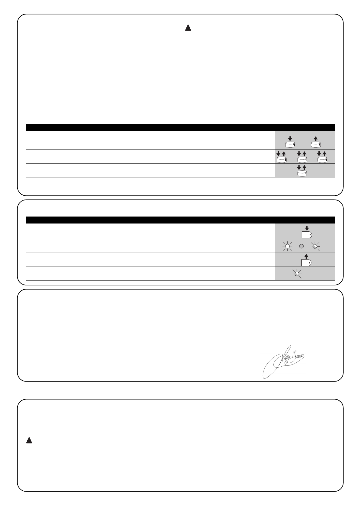
76
1. Mindestens 5 s auf die Taste des neuen Funksenders drücken, dann loslassen.
5s
2. 3-Mal langsam auf die Taste des bereits gespeicherten Funksenders drücken.
1s 1s 1s
3. 1-Mal langsam auf die Taste des neuen Funksenders drücken.
1s
Nun wird der neue Funksender vom Empfänger erkannt und die Merkmale des bereits gespeicherten annehmen. Zur Speicherung weiterer
Sender, alle Schritte für jeden neuen Sender wiederholen.
Tabelle Nr. 10: Fernspeicherung eines Senders Beispiel
4.7.3) Fernspeicherung
Ein neuer Sender kann auch ohne direkte Betätigung der kleinen
Taste am Empfänger gespeichert werden. Man muss dazu über
einen bereits gespeicherten und funktionierenden Sender verfügen.
Der zu speichernde neue Sender wird die Merkmale des bereits
gespeicherten erben; wenn daher der erste Sender in “Modus I”
gespeichert wird, wird auch der neue Sender in “Modus I” gespeichert; in diesem Fall kann auf eine beliebige Taste der Sender
gedrückt werden. Ist der bereits funktionierende Sender dagegen in
“Modus II” gespeichert, so wird auch der neue in Modus II gespeichert und es wird daher sehr wichtig, am ersten Sender die Taste
des gewünschten Steuerbefehls und am zweiten Sender die Taste
zu drücken, der man jenen Steuerbefehl zuteilen will.
Die Fernspeicherung kann in allen Empfängern innerhalb der Reichweite des Senders erfolgen; daher nur den
betreffenden Empfänger gespeist halten.
!
1. Auf die kleine Taste am Empfänger drücken und gedrückt halten
2.
Warten, bis die LED aufleuchtet, dann warten bis sie erlischt und danach warten, dass sie 3-Mal blinkt
x3
3. Die Taste genau während des 3. Blinkens loslassen
4. Falls das Löschen erfolgreich war, wird die LED kurz danach 5-Mal blinken.
x5
Tabelle Nr. 11: Löschen aller Sender Beispiel
4.7.4) Löschen der Funksender
Konformitätserklärung
Nr: 151/SMXI Rev03
Nice S.p.a., Via Pezza Alta 13, 31046 Rustignè di Oderzo (TV) Italien
NICE S.p.a. erklärt, dass die Funkempfänger Modelle SMXI, SMXIS und die jeweiligen Sender FLO2R-S und SM2 mit den wichtigsten Anforderungen der Richtlinie R&TTE 1999/5/CE konform sind, was den Einsatzzweck dieser Geräte betrifft. Hergestellt in Klasse 1, Unterklasse
20
Datum: 19. März 2004 Geschäftsführer
Lauro Buoro
4.7.5) Konformitätserklärung des Funkempfängers
Um höchste Sicherheit zu gewährleisten, ist diese Phase die wichtigste bei der Durchführung der Automatisierung. Die Endprüfung
kann auch als periodische Überprüfung der Vorrichtungen dienen,
aus denen der Automatismus besteht.
die Endprüfung der ganzen Anlage muss von erfahrenem Fachpersonal ausgeführt werden, das zu bestimmen
hat, welche Tests je nach vorhandenen Risiken auszuführen sind, und das die Übereinstimmung mit Gesetzen,
Vorschriften und Verordnungen und insbesondere allen
Anforderungen der Norm EN 12445 zu überprüfen hat, in
der die Testmethoden zur Überprüfung der Automatismen
für Tore angegeben sind.
!
5) Endprüfung und Inbetriebsetzung
Mit beiden Sendern im Aktionsbereich der Automatisierung folgende Schritte ausführen:
Page 77

D
77
5.1) Abnahme
Für jedes einzelne Element des Automatismus wie zum Beispiel
Schaltleisten, Photozellen, Notstops usw. ist eine spezielle Abnahmephase erforderlich; für diese Vorrichtungen sind die Verfahren in
den jeweiligen Anleitungen auszuführen. Für die Abnahme von
ROBUS350 ist folgende Arbeitssequenz durchzuführen:
1. Prüfen, ob alles in der vorliegenden Anweisung und insbesonde-
re das in Kapitel 1 “Hinweise” angegebene genauestens eingehalten ist.
2. Den Toröffner entriegeln, wie in “Entriegelung und Bewegung von
Hand” im Kapitel “Anweisungen und Hinweise für den Benutzer
des Toröffners ROBUS350” angegeben.
3. Prüfen, ob es möglich ist, den Torflügel in Öffnung und Schließung
mit einer Kraft nicht über 390N (ca. 40kg) von Hand zu bewegen
4. Den Toröffner blockieren.
5. Die vorgesehenen Steuervorrichtungen (Schlüsseltaster, Steuerta
sten oder Funksender) verwenden, die Schließung und Öffnung
des Tors testen und prüfen, ob das Verhalten wie vorgesehen ist.
6. Den korrekten Betrieb aller Sicherheitsvorrichtungen der Anlage
einzeln überprüfen (Photozellen, Schaltleisten, Notstops usw.)
und prüfen, ob das Verhalten wie vorgesehen ist. Bei jeder Auslösung einer Vorrichtung wird die BlueBUS-LED an der Steuerung
zweimal schneller blinken und so bestätigen, dass die Steuerung
das Ereignis erkannt hat.
7. Falls die durch die Torbewegung verursachten Gefahren mittels
Begrenzung der Aufprallkraft abgesichert worden sind, muss die
Kraft nach den Verordnungen der Vorschrift EN 12445 gemessen
werden. Falls die “Geschwindigkeitsregelung” und die Kontrolle
der “Motorkraft” als Hilfsmittel für das System zur Aufprallkraftreduzierung benutzt werden, die Einstellungen testen und definieren, mit welcher Einstellung die besten Ergebnisse erzielt werden.
5.2) Inbetriebsetzung
Die Inbetriebsetzung darf erst erfolgen, nachdem alle Endprüfungen von
ROBUS350 sowie der anderen Vorrichtungen erfolgreich beendet sind.
Eine teilweise oder vorübergehende Inbetriebsetzung ist unzulässig.
1. Die technischen Unterlagen der Automatisierung zusammenstellen
und diese mindestens 10 Jahre lang aufbewahren. Sie müssen
mindestens umfassen: Gesamtzeichnung der Automatisierung,
Schaltplan mit den elektrischen Anschlüssen, Risikoanalyse und
jeweilige angewendete Lösungen, Konformitätserklärung des Herstellers für alle benutzten Vorrichtungen (für ROBUS350 die anliegende “CE-Konformitätserklärung” verwenden, Kopie der Bedienungsanweisungen und des Wartungsplans der Automatisierung.
2. Am Tor ein Schild mit mindestens folgenden Daten anbringen:
Automatisierungstyp, Name und Adresse des Herstellers (Verantwortlicher der “Inbetriebsetzung”), Seriennummer, Baujahr und
CE-Markierung.
3. In Tornähe auf bleibende Art ein Etikett oder ein Schild befestigen,
dass die Angaben zur Durchführung der Entriegelung und der
Bewegung von Hand enthält.
4. Die Konformitätserklärung der Automatisierung anfertigen und
dem Inhaber aushändigen.
5. Das Handbuch „Anweisungen und Hinweise für die Bedienung
der Automatisierung“ anfertigen und dem Inhaber der Automatisierung übergeben.
6. Den Wartungsplan anfertigen und dem Inhaber der Automatisierung aushändigen. Er enthält die Wartungsvorschriften der einzelnen Vorrichtungen.
7. Vor der Inbetriebsetzung des Automatismus, den Inhaber auf
geeignete Weise und schriftlich (z.B. in den “Anweisungen und
Hinweise für die Bedienung der Automatisierung”) über die restlichen Gefahren und Risiken informieren.
Dieses Kapitel enthält die Informationen zur Anfertigung des Wartungsplans und für die Entsorgung von ROBUS350
6) Wartung und Entsorgung
6.1) Wartung
Um das Sicherheitsniveau konstant zu halten und die längste
Lebensdauer der ganzen Automatisierung zu gewährleisten, ist eine
regelmäßige Wartung erforderlich.
Die Wartung muss unter genauester Einhaltung der im
vorliegenden Handbuch verzeichneten Sicherheitsbestimmungen und der Verordnungen der gültigen Gesetze und
Vorschriften ausgeführt werden.
Sollten Vorrichtungen vorhanden sein, die anders als ROBUS350
sind, das in ihrem Wartungsplan vorgesehene ausführen.
1. Für ROBUS350 ist max. innerhalb von 6 Monaten oder 10.000
Bewegungen nach der vorherigen Wartung eine programmierte
Wartung erforderlich:
2. Alle elektrischen Versorgungsquellen, inklusive eventuelle Pufferbatterien abtrennen.
3. Die Verschlechterung aller Materialen der Automatisierung überprüfen, mit besonderer Achtung auf Erosions- oder Roststellen an
strukturellen Teilen; Teile, die nicht genügend Garantie gaben,
müssen ersetzt werden.
4. Den Verschleiß der Bewegungselemente überprüfen, wie Ritzel,
Zahnstange und alle Torflügelteile; abgenutzte Teile müssen
ersetzt werden.
5. Die elektrischen Versorgungsquellen wieder anschließen und alle
in Punkt “5.1 Endprüfung” vorgesehenen Tests und Überprüfungen ausführen.
!
6.2) Entsorgung
ROBUS besteht aus verschiedenen Stoffen, von denen einige recycled
werden können (Stahl, Aluminium, Plastik, Elektrokabel), andere müssen dagegen entsorgt werden (Batterien und elektronische Karten).
Einige elektronische Teile und die Batterien könnten
umweltschädliche Stoffe enthalten; nicht in die Umwelt
geben. Informieren Sie sich, wie recycled oder entsorgt
werden kann und halten Sie sich an die örtlich gültigen
Vorschriften.
1. Die Stromversorgung vom Automatismus und die eventuelle Puf-
ferbatterien abtrennen.
2. Alle Vorrichtungen und Zubehörteile demontieren. Hierzu das in Kapitel „3 Installation“ beschriebene Verfahren umgekehrt ausführen.
3. Soweit möglich, Teile trennen, die verschiedenartig recycled oder
entsorgt werden können, zum Beispiel Metall von Plastik, elektronische Karten, Batterien, usw.
4. Sortieren und die so getrennten verschiedenen Materialien autorisierten, örtlichen Recycling- und Entsorgungszentren übergeben.
!
Page 78

78
LED Funktion Beschreibung
L1 Automatische
Diese Funktion ermöglicht die automatische Torschließung nach der programmierten Pausezeit; werkseitig ist
Schließung die Pausezeit auf 30 Sekunden eingestellt, kann aber auf 5, 15, 30, 45, 60 und 80 Sekunden geändert
werden. Falls die Funktion nicht aktiviert ist, ist die Funktionsweise “halbautomatisch”.
L2 Zulauf nach Diese Funktion ermöglicht es, das Tor nur in der zur Durchfahrt nötigen Zeit geöffnet zu halten. In der Tat
Durchfahrt der verursacht die Auslösung von “Foto” immer ein automatisches erneutes Schließen mit einer Pausezeit
Photozelle von 5 Sekunden (unabhängig vom programmierten Wert). Das Verhalten ändert sich je nachdem, ob die
Funktion “Automatische Schließung” aktiviert ist oder nicht.
Mit deaktivierter “Automatischer Schließung”: Das Tor erreicht immer die Position ganz geöffnet
(auch wenn die Photozelle vorher frei wird). Beim Freiwerden der Photozelle wird der automatische Zulauf
mit einer Pause von 5 Sekunden verursacht.
Mit aktivierter “Automatischer Schließung”: die Öffnungsbewegung stoppt gleich nach dem Freiwerden der
Photozellen und es wird der automatische Zulauf mit einer Pause von 5 Sekunden verursacht. Die Funktion “PP, STOP,
OPEN, CLOSE” wird im Falle von Bewegungen, die mit einem Stopbefehl unterbrochen wurden, immer deaktiviert. Wenn
die Funktion “Zulauf nach Durchfahrt der Photozelle” nicht aktiviert ist, wird die Pausezeit wie programmiert sein, oder es
erfolgt kein automatischer Zulauf, wenn die Funktion nicht aktiviert war.
L3 Schließt Immer Die Funktion “Schließt Immer” verursacht eine Schließung, wenn nach einem Stromausfall das Tor
geöffnet ist. Aus Sicherheitsgründen geht der Bewegung ein 5 s langes Vorwarnen voraus. Falls die
Funktion bei der Rückkehr der Stromversorgung nicht aktiviert ist, wird das Tor stehen bleiben.
L4 Stand-By Mit dieser Funktion kann der Verbrauch auf das Geringste reduziert werden. Sie ist besonders mit
Versorgung über Pufferbatterie nützlich. Wenn diese Funktion aktiviert ist, schaltet die Steuerung 1
Minute nach Bewegungsende den Ausgang BLUEBUS (und daher die Vorrichtungen) sowie alle LEDs ab,
mit Ausnahme der LED BLUEBUS, die langsamer blinken wird. Bei Erhalt eines Steuerbefehls wird die
Steuerung ihren Vollbetrieb wieder aufnehmen. Mit nicht aktivierter Funktion erfolgt keine Reduzierung
des Verbrauchs
L5 Anlauf Durch die Aktivierung dieser Funktion wird die allmähliche Beschleunigung beim Beginn jeder Bewegung
abgeschaltet, so dass man die maximale Anlaufkraft hat. Die Funktion ist im Falle starker statischer
Reibungen nützlich, zum Beispiel bei Schnee oder Eis, die den Torflügel blockieren. Wenn die Funktion
Anlauf nicht aktiviert ist, beginnt die Bewegung mit einer allmählichen Beschleunigung.
L6 Vorwarnen Mit der Vorwarnfunktion wird zwischen Einschalten der Blinkleuchte und Bewegungsbeginn eine 3 s
lange Pause hinzugefügt, um die Gefahr vorab zu melden. Wenn die Funktion Vorwarnen nicht aktiviert
ist, erfolgt das Einschalten der Blinkleuchte gleichzeitig mit dem Bewegungsbeginn.
Während des Normalbetriebs von ROBUS350 sind die LEDs L1…L6 je nach dem Status der Funktion, die sie darstellen, ein- oder
ausgeschaltet, zum Beispiel ist L1 eingeschaltet, wenn die Funktion “Automatische Schließung” aktiviert ist.
In den nachfolgenden Kapiteln werden die Möglichkeiten für die Programmierung, eine persönliche Gestaltung, die Diagnose und die Fehlersuche an ROBUS350 behandelt.
7) Weitere Auskünfte
Open Mit Taste “OPEN” kann der Öffnungsbefehl erteilt oder der
▲ Programmierungspunkt nach oben verschoben werden.
Stop Mit Taste “STOP” kann die Bewegung angehalten werden; falls länger
Set als 5 Sekunden gedrückt, dient sie für den Zugriff auf die Programmierung.
Close Mit Taste “CLOSE” kann der Schließbefehl erteilt oder der
▼ Programmierungspunkt nach unten verschoben werden.
7.1) Programmierungstasten
An der Steuerung von ROBUS350 sind 3 Tasten vorhanden, die sowohl zur Schaltung
der Steuerung bei den Tests als auch zu Programmierungen benutzt werden können:
7.2) Programmierungen
Die Steuerung von ROBUS350 verfügt über einige programmierbare
Funktionen; die Einstellung dieser Funktionen erfolgt mit 3 Tasten an
der Steuerung: [▲] [Set] [▼] die Funktionen werden über 6 LEDs
angezeigt: L1…L6
Die an ROBUS350 zur Verfügung stehenden programmierbaren
Funktionen befinden sich auf 2 Niveaus:
Erstes Niveau: ON-OFF-Funktionen (aktiv oder nicht aktiv); in diesem Fall zeigt jede LED eine Funktion an; wenn die LED leuchtet, ist
die Funktion aktiviert, wenn die LED nicht leuchtet, ist die Funktion
deaktiviert – siehe Tabelle Nr. 12.
Zweites Niveau: auf einer Werteskala von 1 bis 6 einstellbare
Parameter; in diesem Fall zeigt jede LED L1…L6 den unter den 6
möglichen eingestellten Wert an - siehe Tabelle Nr. 14.
Tabelle Nr. 12: Liste der programmierbaren Funktionen: erstes Niveau
7.2.1) Funktionen des ersten Niveaus (ON-OFF-Funktionen)
21
Page 79

D
79
Pausezeit
Funktion
Schrittbetrieb
Motorgeschwindigkeit
Ausgang
S.C.A.
Motorkraft
Teilöffnung
L1
L2
L3
L4
L5
L6
L1
L2
L3
L4
L5
L6
L1
L2
L3
L4
L5
L6
L1
L2
L3
L4
L5
L6
L1
L2
L3
L4
L5
L6
L1
L2
L3
L4
L5
L6
5 Sekunden
15 Sekunden
30 Sekunden
45 Sekunden
60 Sekunden
80 Sekunden
Öffnet - Stop – Schließt - Stop
Öffnet - Stop – Schließt - Stop
Öffnet - Schließt- Öffnet – Schließt
Wohnblockbetrieb
Schließt
Todmannfunktion
Sehr langsam
Langsam
Mittel
Schnell
Sehr schnell
Sehr sehr schnell
Funktion S.C.A. (Kontrolllampe Tor Geöffnet)
Leuchtet, wenn Tor geschlossen
Leuchtet, wenn Tor geöffnet
Aktiv mit 2. Funkbefehl
Aktiv mit 3. Funkbefehl
Aktiv mit 4. Funkbefehl
Tor “sehr leicht”
Tor “leicht”
Tor “mittel”
Tor “mittel-schwer”
Tor “schwer”
Tor “sehr schwer”
0,5 m
1 m
1,5 m
2 m
2,5 m
3 m
7.2.2) Erstes Niveau - Programmierungen (ON-OFF-Funktionen)
Werkseitig sind alle Funktionen des ersten Niveaus auf “OFF”, was man aber jederzeit ändern kann, wie in Tabelle Nr. 13 angegeben. Bei der
Durchführung des Verfahrens vorsichtig sein, da die Zeitgrenze 10 s zwischen dem Druck auf eine Taste und die andere beträgt. Andernfalls
wird das Verfahren automatisch beendet, mit Speicherung der bisher ausgeführten Änderungen.
1. Auf Taste [Set] drücken und ca. 3 Sekunden gedrückt halten
3s
2. Taste [Set] loslassen, wenn LED L1 zu blinken beginnt
L1
3. Auf die Tasten [▲] oder [▼] drücken, um das Blinken auf die LED zu verschieben, welche die
zu ändernde Funktion darstellt o
4. Auf Taste [Set] drücken, um den Status der Funktion zu ändern
(kurzes Blinken = OFF; langes Blinken = ON)
5. 10 s warten, um die Programmierung aufgrund des Ablaufs der Zeitgrenze zu beenden.
10s
Anmerkung: die Punkte 3 und 4 können während derselben Programmierungsphase wiederholt werden, um andere Funktionen auf ON
oder OFF zu stellen
Tabelle Nr. 13: Änderung der ON-OFF-Funktionen Beispiel
SET
SET
SET
7.2.3) Funktionen des zweiten Niveaus (einstellbare Parameter)
Tabelle Nr. 14: Liste der programmierbaren Funktionen: zweites Niveau
Eingangs-LED Parameter LED (Niveau) Wert Beschreibung
Stellt die Pausezeit bzw. die Zeit vor dem
automatischen Zulauf. Wirkt nur, falls die
automatische Schließung aktiviert ist.
Stellt die Sequenz der Steuerbefehle ein,
die dem Eingang Schrittbetrieb oder dem
1. Funkbefehl zugeteilt sind (siehe die
Tabellen 4 und 5).
Stellt die Motorgeschwindigkeit beim normalen Lauf ein.
Stellt die Funktion ein, die dem Ausgang
S.C.A. zugeordnet ist.
Stellt das Kontrollsystem der Motorkraft ein
und passt diese dem Torgewicht an
Stellt das Maß der Teilöffnung ein. Der
Befehl für Teilöffnung kann nur mit dem 2.
Funkbefehl erteilt werden (siehe die Tabellen 4 und 5)
Anmerkung: “ ” ist die werkseitige Einstellung
L1
L2
L3
L4
L5
L6
Page 80

80
7.2.4) Programmierung zweiten Niveaus (einstellbare Parameter)
Werkseitig sind diese Parameter wie in Tabelle “ “ eingestellt, sie können aber wie in Tabelle Nr. 15 angegeben jederzeit geändert werden.
Bei der Durchführung des Verfahrens vorsichtig sein, da die Zeitgrenze 10 s zwischen dem Druck auf eine Taste und die andere beträgt.
Andernfalls wird das Verfahren automatisch beendet, mit Speicherung der bisher ausgeführten Änderungen.
1. Auf Taste [Set] drücken und ca. 3 Sekunden gedrückt halten
3s
2. Taste [Set] loslassen, wenn LED L1 zu blinken beginnt
L1
3. Auf die Tasten [▲] oder [▼] drücken, um das Blinken auf die „Eingangs-LED“ zu verschieben,
die den zu ändernden Parameter darstellt o
4. Auf Taste [Set] drücken und gedrückt halten; die Taste [Set] muss während der Schritte 5 und 6
ständig gedrückt bleiben
5. Ca. 3 s warten, danach wird die LED aufleuchten, die das aktuelle Niveau des zu ändernden
Parameters darstellt
6. Auf die Tasten [▲] oder [▼] drücken, um die LED zu verschieben, die den Wert des Parameters darstellt
o
7. Die Taste [Set] loslassen
8. 10 s warten, um die Programmierung aufgrund des Ablaufs der Zeitgrenze zu beenden.
10s
Anmerkung: die Punkte von 3 bis 7 können während derselben Programmierungsphase wiederholt werden, um andere Parameter
einzustellen
Tabelle Nr. 15: Änderung der einstellbaren Parameter Beispiel
SET
SET
SET
SET
7.2.5) Erstes Niveau - Programmierungsbeispiel (ON-OFF-Funktionen)
Als Beispiel wird die Sequenz der Vorgänge angegeben, die auszuführen sind, um die werkseitige Einstellung zur Aktivierung der Funktionen
“Automatische Schließung” (L1) und “Schließt Immer” (L3) zu ändern.
1. Auf Taste [Set] drücken und ca. 3 Sekunden gedrückt halten
3s
2. Taste [Set] loslassen, wenn LED L1 zu blinken beginnt
L1
3. Einmal auf Taste [Set] drücken, um den Status der L1 zugeteilten Funktion (Automatische Schließung)
zu ändern. Die LED L1 blinkt nun lang. L1
4. Zweimal auf Taste [▼] drücken, damit das Blinken auf LED L3 übergeht
L3
5. Einmal auf Taste [Set] drücken, um den Status der L3 zugeteilten Funktion (Schließt Immer) zu ändern.
Die LED L3 blinkt nun lang
6. 10 s warten, um die Programmierung aufgrund des Ablaufs der Zeitgrenze zu beenden.
10s
Am Ende dieser Vorgänge müssen die LEDS L1 und L3 eingeschaltet bleiben, was bedeutet, dass die Funktionen “Automatische
Schließung” und “Schließt Immer” aktiviert sind.
Tabelle Nr. 16: Erstes Niveau - Programmierungsbeispiel Beispiel
SET
SET
SET
SET
Alle Parameter können beliebig ohne Nebenwirkungen eingestellt
werden, nur für die Einstellung der “Motorkraft” ist besondere Vorsicht notwendig:
•Keine hohen Kraftwerte benutzen, um der Tatsache abzuhelfen,
dass das Tor starke Reibungspunkte hat. Eine zu starke Kraft kann
das Sicherheitssystem beeinträchtigen und das Tor beschädigen.
•Falls die Kontrolle der “Motorkraft” als Hilfsmittel für das System zur
Aufprallkraftreduzierung benutzt wird, die Kraftmessung nach jeder
Einstellung wiederholen, wie von Norm EN 12445 vorgesehen.
•Verschleiß und Witterung kann die Torbewegungen beeinflussen;
eine neue Einstellung könnte in regelmäßigen Abständen notwendig sein.
Page 81

D
81
7.2.6) Zweites Niveau - Programmierungsbeispiel (einstellbare Parameter)
Als Beispiel wird die Sequenz der Vorgänge angegeben, die auszuführen sind, um die werkseitige Einstellung der Parameter zu ändern und
die “Pausezeit” auf 60 s (Eingang an L1 und Niveau auf L5) zu erhöhen und die “Motorkraft” für leichte Tore (Eingang an L5 und Niveau auf
L2) zu reduzieren.
1. Auf Taste [Set] drücken und ca. 3 Sekunden gedrückt halten
3s
2. Taste [Set] loslassen, wenn LED L1 zu blinken beginnt
L1
3. Auf Taste [Set] drücken und gedrückt halten; die Taste [Set] muss während der Schritte 4 und 5
ständig gedrückt bleiben
4. Ca. 3 s warten, danach wird die LED L3 aufleuchten, die das aktuelle Niveau der “Pausezeit” darstellt
L3 3s
5. Zweimal auf Taste [▼] drücken, damit das Blinken auf LED L5 übergeht, die den neuen
Wert der “Pausezeit” darstellt L5
6. Taste [Set] loslassen
7. Viermal auf Taste [▼] drücken, damit das Blinken auf LED L5 übergeht
L5
8. Auf Taste [Set] drücken und gedrückt halten; die Taste [Set] muss während der Schritte
9 und 10 ständig gedrückt bleiben
9. Ca. 3 s warten, danach wird die LED L5 aufleuchten, die das aktuelle Niveau der “Motorkraft” darstellt
L3 3s
10. Dreimal auf Taste [▲] drücken, damit das Blinken auf LED L2 übergeht, die den neuen
Wert der “Motorkraft” darstellt L2
11. Taste [Set] loslassen
12. 10 s warten, um die Programmierung aufgrund des Ablaufs der Zeitgrenze zu beenden.
10s
Tabelle Nr.17: Zweites Niveau - Programmierungsbeispiel Beispiel
SET
SET
SET
SET
SET
SET
7.3) Hinzufügen oder Entfernen von Vorrichtungen
Einer Automatisierung mit ROBUS350 können jederzeit Vorrichtungen
hinzugefügt bzw. aus dieser entfernt werden. Insbesondere können am
“BLUEBUS” sowie am Eingang “STOP” verschiedenartige Vorrichtungen
angeschlossen werden, wie in den Paragraphen “7.3.1BlueBUS” und
“7.3.2 Eingang STOP” angegeben.”.
7.3.1) BlueBUS
BlueBUS ist eine Technik, mit der die Verbindungen der kompatiblen
Vorrichtungen mit nur zwei Leitern ausgeführt werden können, die
sowohl Stromversorgung als auch Kommunikationssignale übertragen. Alle Vorrichtungen werden an diesen 2 Leitern des BlueBUS
parallelgeschaltet, ohne dass eine Polung beachtet werden muss;
jede Vorrichtung wird einzeln erkannt, da ihr während der Installation
eine eindeutige Adresse zugeteilt wird. An BlueBUS können zum
Beispiel Photozellen, Sicherheitsvorrichtungen, Schalttasten, Kontrolllampen usw. angeschlossen werden. Die Steuerung von
ROBUS350 erkennt über eine entsprechende Erlernungsphase alle
angeschlossenen Vorrichtungen nacheinander und ist imstande, alle
möglichen Störungen mit größter Sicherheit wahrzunehmen. Aus
diesem Grund muss an der Steuerung jedes Mal, wenn eine mit BlueBUS verbundene Vorrichtung hinzugefügt oder entfernt wird, die
Erlernung durchführt werden, wie in Paragraph “7.2.4 Erlernung sonstiger Vorrichtungen” beschrieben.
7.3.2) Eingang STOP
STOP ist der Eingang, der das unverzügliche Anhalten der Bewegung verursacht, gefolgt von einer kurzen Umkehrung. An diesen
Eingang können Vorrichtungen mit Ausgang mit gewöhnlich geöffnetem “NO”-Kontakt, mit gewöhnlich geschlossenem “NC”-Kontakt
oder Vorrichtungen mit Ausgang mit konstantem 8,2kΩ Widerstand,
wie zum Beispiel Schaltleisten, angeschlossen werden.
Wie für BlueBUS erlernt die Steuerung auch die am Eingang STOP
angeschlossene Vorrichtung während der Erlernung – siehe Paragraph “7.2.4 Erlernung sonstiger Vorrichtungen”; danach wird ein
STOP verursacht, wenn eine beliebige Variation des erlernten Status
erfolgt.
Con opportuni accorgimenti è possibile collegare all’ingresso STOP
più di un dispositivo, anche di tipo diverso:
• Mit entsprechenden Maßnahmen kann am Eingang STOP mehr
als eine Vorrichtung auch anderen Typs angeschlossen werden.
• Mehrere NO-Vorrichtungen können miteinander in unbegrenzter
Menge parallelgeschaltet werden.
• 2 Vorrichtungen mit Ausgang mit konstantem 8,2kΩ Widerstand
können parallelgeschaltet werden; im Falle von mehr als 2 Vorrichtungen müssen alle mit nur einem 8,2kΩ Endwiderstand “kaskadengeschaltet” werden.
• Die Kombination NO und NC ist möglich, wenn die 2 Kontakte
parallelgeschaltet werden, wobei ein 8,2kΩ Widerstand mit dem
NC-Kontakt seriengeschaltet werden muss (daher ist auch die
Kombination von 3 Vorrichtungen NO, NC und 8,2kΩ möglich).
Falls der Eingang STOP für den Anschluss von Vorrichtungen mit Sicherheitsfunktionen benutzt wird, garantieren nur die Vorrichtungen mit Ausgang mit konstantem
8,2kΩ Widerstand die Sicherheitsklasse 3 gegen Defekte
gemäß der Vorschrift EN 954-1.
!
Page 82

82
FOTO
Photozelle außen H = 50
mit Auslösung in Schließung
FOTO II
Photozelle außen H = 100
mit Auslösung in Schließung
FOTO 1
Photozelle innen H = 50
mit Auslösung in Schließung
FOTO 1 II
Photozelle innen H = 100
mit Auslösung in Schließung
FOTO 2
Photozelle außen
mit Auslösung in Öffnung
FOTO 2 II
Photozelle innen
mit Auslösung in Öffnung
FOTO 3
Nur eine Photozelle für
den ganzen Automatismus
wenn FOTO 3 zusammen mit FOTO II installiert wird, muss die
Position der Photozellenelemente (TX-RX) so sein, wie in der
Anweisung der Photozellen angegeben.
!
7.3.3) Photozellen
Das “BlueBUS” System ermöglicht es durch die Adressierung mit
dazu vorgesehenen Überbrückungen, dass die Steuerung Photozellen erkennt und die korrekte Detektionsfunktion zugeteilt werden
kann. Die Adressierung muss sowohl an TX als auch an RX ausgeführt werden (die Überbrückungen gleich stellen), wobei zu prüfen
ist, dass keine weiteren Photozellenpaare mit derselben Adressierung vorhanden sind. An einem Automatismus für Schiebetore mit
ROBUS350 können die Photozellen nach Abbildung 22. installiert
werden. Nach Installation bzw. Entfernung von Photozellen muss an
der Steuerung die Erlernphase ausgeführt werden, wie in Paragraph
“7.3.4 Erlernung sonstiger Vorrichtungen” beschrieben.
22
Tabelle Nr. 18: Adressierungen der Photozellen
Photozelle Überbrückungen Photozelle Überbrückungen
7.3.4) Erlernung sonstiger Vorrichtungen
Gewöhnlich wird der Erlernungsvorgang der an BlueBUS und an Eingang STOP angeschlossenen Vorrichtungen während der Installation
ausgeführt, wenn jedoch Vorrichtungen hinzugefügt bzw. entfernt werden, kann die Erlernung wie folgt wiederholt werden:
1. Auf die Tasten [▲] und [Set] drücken und gedrückt halten
2. Die Tasten loslassen, wenn die LEDs L1 und L2 sehr schnell zu blinken beginnen (nach ca. 3 s)
L1 L2
3. Ein paar Sekunden warten, damit die Steuerung die Erlernung der Vorrichtungen beendet.
4. Am Ende der Erlernung dürfen die LEDs L1 und L2 nicht mehr blinken, die LED STOP muss eingeschaltet
bleiben, wogegen die LEDs L1…L6 je nach dem Status ihrer ON-OFF-Funktionen aufleuchten werden. L1 L2
Nachdem Vorrichtungen hinzugefügt bzw. entfernt worden sind, muss die Endprüfung der Automatisierung gemäß “5.1 End-
prüfung” erneut ausgeführt werden.
!
Tabelle Nr. 19: Erlernung sonstiger Vorrichtungen Beispiel
SET
SET
7.4.1) Funktion “Öffnet Immer”
Die Funktion “Öffnet Immer” ist eine Besonderheit der Steuerung, mit
der immer eine Öffnungsbewegung erfolgt, wenn der Befehl “Schrittbetrieb” länger als 2 Sekunden gegeben wird; das ist zum Beispiel
nützlich, um an Klemme Schrittbetrieb den Kontakt einer Zeituhr
anzuschließen, damit das Tor in einer bestimmten Zeitspanne geöffnet bleibt. Diese Sonderfunktion ist unabhängig von der Program-
mierung des Eingangs Schrittbetrieb vorhanden; eine Ausnahme ist
die Programmierung des Eingangs Schrittbetrieb als „Schließt“ – siehe Parameter “Funktion Schrittbetrieb” in Tabelle Nr. 14.
7.4.2) Funktion “Todmann”
Wenn eine Sicherheitsvorrichtung nicht korrekt funktionieren oder außer
Betrieb sein sollte, kann das Tor in der Modalität “Todmann” bewegt
werden. Für Einzelheiten wird auf den Paragraph “Torbewegung
mit Sicherheitsvorrichtungen außer Betrieb” in der Anlage “Anweisungen und Hinweise für den Benutzer des Toröffners ROBUS”.
7.4) Sonderfunktionen
Page 83
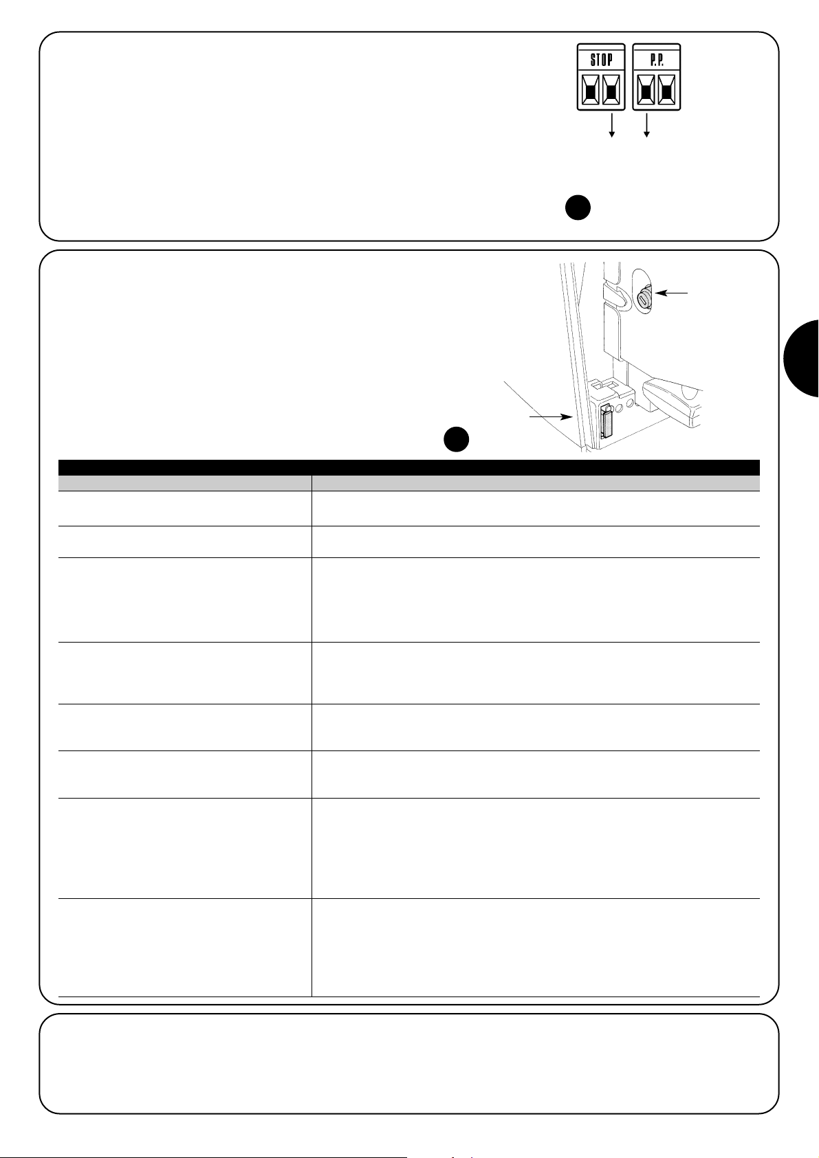
D
83
7.6) Probleme und deren Lösungen
In Tabelle Nr. 20 sind nützliche Hinweise zu finden, um eventuellen
Betriebsstörungen entgegen zu treten, die bei der Installation oder im
Falle von Defekten auftreten können.
7.7) Diagnose und Anzeigen
Einige Vorrichtungen bieten selbst besondere Anzeigen, mit denen
der Betriebsstatus oder eventuelle Störungen erkannt werden können.
24
Tabelle Nr. 20: Fehlersuche
Symptome Empfohlene Überprüfungen
Der Funksender schaltet das Tor nicht und die
LED am Sender leuchtet nicht auf
Der Funksender schaltet das Tor nicht, aber die
LED am Sender leuchtet auf
Es erfolgt keine Bewegung und die LED “BLUEBUS” blinkt nicht
Es erfolgt keine Bewegung und die Blinkleuchte
blinkt nicht
Es erfolgt keine Bewegung und die Blinkleuchte
blinkt mehrmals.
Die Bewegung beginnt, aber gleich danach
erfolgt die Umkehrung
Die Bewegung wird ordnungsgemäß ausgeführt,
aber die Blinkleuchte funktioniert nicht
Die Bewegung wird ordnungsgemäß ausgeführt,
aber die Kontrolllampe SCA funktioniert nicht
Prüfen, ob die Batterien des Senders leer sind, ggf. auswechseln
Prüfen, ob der Sender korrekt im Funkempfänger gespeichert ist
Prüfen, ob ROBUS350 mit der 230V Netzspannung gespeist ist. Prüfen, ob die Sicherungen unterbrochen sind; in diesem Fall die Ursache des Defekts überprüfen, dann
die Sicherungen mit anderen mit demselben Stromwert und denselben Merkmalen
auswechseln.
Prüfen, ob der Befehl effektiv empfangen wird. Falls der Befehl am Eingang Schrittbetrieb angelangt, muss die jeweilige LED “PP” aufleuchten, falls dagegen der Funksender benutzt wird, muss die LED “BLUEBUS” 2-Mal schnell blinken.
Zählen, wie oft die Blinkleuchte blinkt und nach den Angaben in Tabelle Nr. 21 überprüfen.
Die gewählte Kraft könnte für den Tortyp zu gering sein. Prüfen, ob Hindernisse
vorhanden sind und ggf. eine stärkere Kraft wählen.
Prüfen, ob während der Bewegung Spannung an Klemme FLASH der Blinkleuchte anliegt
(da intermittierend, ist der Spannungswert nicht hoch, ca. 10-30Vac); falls Spannung
anliegt, ist das Problem durch die Glühbirne verursacht, die mit einer mit denselben Merkmalen ausgewechselt werden muss. Falls keine Spannung anliegt, könnte eine Überlast am
Ausgang FLASH vorhanden sein – das Kabel auf Kurzschluss überprüfen.
Den für Ausgang SCA programmierten Funktionsstatus überprüfen (Tabelle Nr. 14). Wenn
die Kontrolllampe leuchten müsste, prüfen ob Spannung an der Klemme SCA anliegt (ca.
24Vcc); falls Spannung vorhanden ist, ist das Problem durch die Kontrolllampe verursacht,
die mit einer mit denselben Merkmalen ausgewechselt werden muss. Falls keine Spannung
anliegt, könnte eine Überlast am Ausgang SCA vorhanden sein – das Kabel auf Kurzschluss überprüfen.
7.5) Verbindung sonstiger Vorrichtungen
Sollte es notwendig sein, externe Vorrichtungen wie zum Beispiel
einen Proximity-Leser für Transponder-Cards oder die Beleuchtung
des Schlüsseltasters anzuschließen, kann die Versorgung wie in
Abbildung 23 gezeigt entnommen werden.
Die Versorgungsspannung ist 24Vcc -30% ÷ +50% mit 100 mA zur
Verfügung stehendem Höchststrom.
-+
24Vcc
23
F2
F1
Page 84

84
Led BLUEBUS Ursache HANDLUNG
Led STOP Ursache HANDLUNG
Led P.P. Ursache HANDLUNG
Aus
7.7.2) Anzeigen durch die Steuerung
An der Steuerung von ROBUS350 befinden sich verschiedene
LEDs, von denen jede sowohl im Normalbetrieb als auch bei Störungen besondere Anzeigen geben kann.
Tabelle Nr. 22: LEDs an den Klemmen der Steuerung
Störung
Prüfen, ob die Stromversorgung vorhanden ist; prüfen, ob die Sicherungen
ausgelöst wurden; ggf. die Ursache des Defekts überprüfen, dann die Sicherungen mit anderen mit denselben Merkmalen auswechseln
Ein Schwere Störung
Eine schwere Störung liegt vor, versuchen, die Steuerung ein paar Sekunden
abzuschalten; falls dieser Status bleibt, ist ein Defekt vorhanden und die elektronische Steuerkarte muss ausgewechselt werden
1-Mal Blinken pro Sekunde Alles OK Normalbetrieb der Steuerung
2-Mal Schnellblinken
Es erfolgte eine Statusvariation der Eingänge
Ist normal, wenn eine Änderung eines der Eingänge P.P., STOP erfolgt oder die
Photozellen ansprechen oder der Funksender benutzt wird
Mehrmaliges Blinken mit 1
Sekunde Pause
Verschiedenes
Ist dieselbe Anzeige, die an der Blinkleuchte gegeben wird. Siehe Tabelle
Nr. 21
Aus
Auslösung des Eingangs
STOP
Die am Eingang STOP angeschlossenen Vorrichtungen überprüfen
Ein Alles OK Eingang STOP aktiv
Aus Alles OK Eingang PP nicht aktiv
Ein
Auslösung des Eingangs
PP
Ist normal, wenn die an Eingang PP angeschlossene Vorrichtung effektiv
aktiviert ist
25
6-Mal Blinken
1 Sekunde Pause
6-Mal Blinken
Die Überprüfung der am BLUEBUS angeschlossenen Vorrichtungen bei
Bewegungsbeginn entspricht nicht dem während der Erlernung Gespeicherten. Es können defekte Vorrichtungen vorhanden sein: überprüfen und
auswechseln; falls Änderungen ausgeführt worden sind, muss die Erlernung
wiederholt werden (7.3.4 Erlernung sonstiger Vorrichtungen).
7.7.1) Anzeigen durch die Blinkleuchte
Die Blinkleuchtenanzeige FLASH blinkt während der Bewegung einmal pro Sekunde; im Falle von Störungen wird das Blinken schneller sein;
die Blinkvorgänge wiederholen sich zweimal mit einer Pause von einer Sekunde.
Tabelle Nr. 21: Anzeigen durch die Blinkleuchte FLASH
Schnellblinken Ursache HANDLUNG
1-Mal Blinken
1 Sekunde Pause
1-Mal Blinken
Fehler an BlueBUS
2-Mal Blinken
1 Sekunde Pause
2-Mal Blinken
Auslösung einer Photozelle
Bei Bewegungsbeginn wird die Zustimmung zur Bewegung von einer oder
mehreren Photozellen nicht gegeben; prüfen, ob Hindernisse vorhanden sind.
Während der Bewegung ist das normal, wenn effektiv ein Hindernis vorhanden ist.
3-Mal Blinken
1 Sekunde Pause
3-Mal Blinken
Auslösung des “Motorkraft”-Begrenzers
Während der Bewegung war mehr Reibung am Tor vorhanden;
Ursache überprüfen
4-Mal Blinken
1 Sekunde Pause
4-Mal Blinken
Auslösung des Eingangs
STOP
Am Anfang und während der Bewegung erfolgte eine Auslösung des Eingangs STOP; Ursache überprüfen.
5-Mal Blinken
1 Sekunde Pause
5-Mal Blinken
Fehler in den internen Parametern der elektronischen
Steuerung. Mindestens 30 Sekunden warten und den Befehl erneut erteilen;
sollte dieser Status bleiben, könnte ein schwerer Defekt vorhanden sein, und
die elektronische Steuerkarte muss ausgewechselt werden
Die Höchstgrenze an
Bewegungen pro Stunde
wurde überschritten.
Ein paar Minuten warten, bis der Bewegungsbegrenzer wieder unter die
Höchstgrenze zurückkehrt
7-Mal Blinken
1 Sekunde Pause
7-Mal Blinken
Fehler in den internen elektrischen Kreisläufen
Alle Versorgungskreisläufe ein paar Sekunden lang abtrennen, dann einen Befehl
erteilen; sollte dieser Status bleiben, könnte ein schwerer Defekt vorhanden sein,
und die elektronische Steuerkarte muss ausgewechselt werden.
Page 85

D
85
7.8) Zubehör
Für ROBUS350 ist folgendes Sonderzubehör vorgesehen:
• PS124 24V – 1,2 Ah Pufferbatterie mit eingebautem Batterieladegerät.
Für die vollständige und aktuelle Liste der Zubehörteile siehe den
Produktkatalog der Nice S.p.a.
26
Led 1 Beschreibung
• Programmierung der Funktionen im Gang
• Falls L3 zusammen mit L4 blinkt, muss die Erlernung der Torflügellänge ausgeführt werden (siehe Paragraph “4.4 Erlernung der Torflügellänge”).
Led L6 Beschreibung
Led L5 Beschreibung
Led L3 Beschreibung
Led L2 Beschreibung
Led L4
Beschreibung
Zeigt beim Normalbetrieb an: “Anlauf” nicht aktiv.Aus
Aus
Tabelle Nr. 23: LEDs an den Tasten der Steuerung
Zeigt beim Normalbetrieb an: “Automatische Schießung” nicht aktiv
Zeigt beim Normalbetrieb an: “Automatische Schießung” aktiv
• Programmierung der Funktionen im Gang
• Falls L1 zusammen mit L2 blinkt, muss die Erlernung der Vorrichtungen ausgeführt werden (siehe Paragraph “4.3 Erlernung der Vorrichtungen”).
Ein
Blinkt
Aus Zeigt beim Normalbetrieb an: “Schließt Immer” nicht aktiv.
Zeigt beim Normalbetrieb an: “Schließt Immer” aktiv.
• Programmierung der Funktionen im Gang
• Falls L3 zusammen mit L4 blinkt, muss die Erlernung der Torflügellänge ausgeführt werden (siehe Paragraph “4.4 Erlernung der Torflügellänge”).
Ein
Blinkt
Aus Zeigt beim Normalbetrieb an: “Schließt Immer” nicht aktiv.
Zeigt beim Normalbetrieb an: “Schließt Immer” aktiv.
Zeigt beim Normalbetrieb an: “Stand-By” nicht aktiv.
Zeigt beim Normalbetrieb an: “Stand-By” aktiv.
• Programmierung der Funktionen im Gang
• Falls L4 zusammen mit L3 blinkt, muss die Erlernung der Torflügellänge ausgeführt werden (siehe Paragraph “4.4 Erlernung der Torflügellänge”).
Ein
Blinkt
Aus
Ein
Blinkt
Zeigt beim Normalbetrieb an: “Anlauf” aktiv.
Programmierung der Funktionen im Gang
Ein
Blinkt
Zeigt beim Normalbetrieb an: “Vorwarnen” nicht aktiv.
Zeigt beim Normalbetrieb an: “Vorwarnen” aktiv.
Programmierung der Funktionen im Gang
Aus
Ein
Blinkt
27
Page 86

Abgestrahlte Leistung
Abmessungen und Gewicht
Von 100 bis 150 m. Diese Entfernung kann bei Vorhandensein von Hindernissen und elektromagneti-
schen Störungen variieren und ist durch die Position der Empfangsantenne beeinflusst.
Benutzung in säure- und salzhaltiger oder
explosionsgefährdeter Atmosphäre
330 x 195 h 277; 8Kg
Für eine Verbesserung der Produkte behält sich NICE S.p.a. das Recht vor, die technischen Merkmale jederzeit und ohne vorherige Benachrichtigung zu ändern, wobei aber vorgesehene Funktionalitäten und Einsätze erhalten bleiben.
Alle technischen Merkmale beziehen sich auf eine Temperatur von 20°C (±5°C)
8) Technische Merkmale
Typik
Technische Merkmale: ROBUS350
Elektromechanischer Toröffner für die automatische Bewegung von Schiebetoren an Wohn-
gebäuden, komplett mit elektronischer Steuerung
Ritzel Z: 15; Modul: 4; Teilung: 12,6 mm; Teilkreisdurchmesser: 60 mm
Max. Anlaufdrehmoment
10Nm; entspricht der Fähigkeit, einen Torflügel mit statischer Reibung bis zu 333N in Bewegung zu setzen
Nenndrehmoment
6Nm; entspricht der Fähigkeit, einen Torflügel mit dynamischer Reibung bis zu 200N in Bewegung zu halten
Geschwindigkeit mit Nenndrehmoment
0,18m/s
Geschwindigkeit ohne Last (die Steuerung ermö-
glicht die Programmierung von 6 Geschwindigkeiten gleich ca. 100, 85, 70, 55, 45, 30%)
0,34m/s
Max. Anzahl der Betriebszyklen
50 Zyklen pro Tag (die Steuerung begrenzt die Anzahl der Zyklen auf das maximal Vorgesehene –
siehe die Tabellen Nr. 1 und 2)
Höchstzeit Dauerbetrieb
10 Minuten (die Steuerung begrenzt den Dauerbetrieb auf das maximal Vorgesehene – siehe
die Tabellen Nr. 1 und 2)
Einsatzgrenzen
Gewöhnlich ist ROBUS350 imstande, Tore mit einem Gewicht bis 350 Kg oder einer Länge bis 15 m
zu nach den in den Tabellen Nr. 1 und 2 vorgesehenen Grenzen zu automatisieren
Max. Leistungsaufnahme 250VA
Isolationsklasse 1 (Sicherheitserdung ist erforderlich)
Notversorgung Mit Sonderzubehör PS124
Ausgang Blinkleuchte Für 1 Blinkleuchte LUCYB (Glühbirne 12V, 21W)
Ausgang BLUEBUS Ein Ausgang mit einer Höchstlast von 15 Bluebus Einheiten
Eingang STOP
Für gewöhnlich geschlossene, gewöhnlich geöffnete Kontakte oder mit konstantem 8,2kΩ
Widerstand; in Selbsterlernung (eine Variation im Vergleich zum gespeicherten Status verursa-
cht den Steuerbefehl “STOP”)
Eingang PP
Für gewöhnlich geöffnete Kontakte (das Schließen des Kontaktesverursacht den Steuerbefehl P.P. =
Schrittbetrieb)
Eingang Funkantenne 52Ω für Kabel Typ RG58 oder ähnliche
Versorgung ROBUS350
Versorgung ROBUS350/V1
230Vac (+10% +15%) 50/60Hz.
120Vac (+10% +15%) 50/60Hz.
Programmierbare Funktionen 6 ON-OFF-Funktionen und 6 einstellbare Funktionen (siehe die Tabellen Nr. 12 und 14)
Betriebstemperatur -20°C ÷ 50°C
Nein
Schutzart IP 44
Abmessungen und Gewicht
Funktionen in Selbsterlernung
Selbsterlernung der am Ausgang BlueBUS angeschlossenen Vorrichtungen Selbsterlernung
der“STOP”-Vorrichtung (NO-Kontakt, NC-Kontakt oder 8,2kΩ Widerstand). Selbsterlernung der
Torlänge und Berechnung der Stellen, an denen die Verlangsamung und die Teilöffnung erfolgt.
Ausgänge 4 (an Verbinder SM)
Betriebstemperatur
-10°C ÷ 55°C
Typik
Technische Merkmale Funkempfänger: SMXI Funkempfänger: SMXIS
4-kanaliger Empfänger für Funksteuerung
Frequenz 433.92MHz
Codierung Digital Rolling Code 52 Bit, Typ FLOR Digital Rolling Code 64 Bit, Typ SMILO
Kompatibilität der Sender
FLOR, VERY VR; nur Einzelgruppe: ERGO,
PLANO, PLANOTIME
SMILO
Speicherbare Sender Bis zu 256, falls im Modus I gespeichert
Eingangsimpedanz 52Ω
Empfindlichkeit besser als 0.5µV
Reichweite der Sender
72 x 40 h 18mm / 30g Durchmesser 48 h14mm / 18g
Typik 2-kanaliger Sender für Funksteuerung
Frequenz 433.92MHz
Codierung Digital Rolling Code 52 Bit, Typ FLOR Digital Rolling Code 64 Bit, Typ SMILO
Tasten 2
Versorgung 12Vdc mit 23A Batterie
Aufnahme 25mA
Dauer der Batterien
1 Jahre, geschätzt auf 10 Befehlen/Tag mit einer Dauer von 1s bei 20°C (bei niedrigen Temperaturen
verkürzt sich die Dauer der Batterien)
100µW
Technische Merkmale Sender: FLO2R-S Sender: SM2
86
Page 87

D
87
Wir gratulieren Ihnen zu Ihrer Wahl eines Nice Produk-
tes für Ihre Automatisierung! Nice S.p.A. stellt Bestandteile für die Automatisierung von Türen und Toren, Rollladen,
Behängen und Markisen her, wie Getriebemotoren, Steuerungen, Funksteuerungen, Blinkleuchten, Photozellen und
Zubehör. Nice verwendet ausschließlich Werkstoffe und
Verarbeitungen hochstehender Qualität und ist aufgrund
der Nice Betriebsphilosophie immer auf der Suche nach
innovativen Lösungen, um die Verwendung der Nice
Apparaturen, vom technischen, ästhetischen und ergonomischen Standpunkt her besonders gepflegt, zu erleichtern: Ihr Installateur wird bestimmt das richtige Produkt in
der großen Nice Palette für Sie ausgewählt haben. Nice ist
jedoch nicht der Hersteller Ihrer Automatisierung, die das
Ergebnis von Analysen, Bewertungen, Auswahl der Materialien und der Durchführung der Anlage durch Ihren Vertrauensinstallateur ist. Jede Automatisierung ist einzigartig, und nur Ihr Installateur besitzt die Erfahrung und Professionalität, die notwendig sind, um eine Anlage nach
Ihrem Bedarf auszuführen, die sicher und dauerhaft zuverlässig und vor allem fachgerecht ist bzw. den gültigen Vorschriften entspricht. Eine Automatisierungsanlage ist
etwas sehr bequemes, aber auch ein wertvolles Sicherheitssystem und dauert mit nur wenigen Eingriffen
bestimmt jahrelang. Auch wenn Ihre Automatisierung den
von den Vorschriften geforderten Sicherheitsniveaus entspricht, schließt dies das Vorhandensein von “Restrisiken”
nicht aus, womit die Möglichkeit gemeint ist, dass
gewöhnlich aufgrund eines verantwortungslosen oder
falschen Gebrauchs Gefahren erzeugt werden können; wir
möchten Ihnen deshalb ein paar Ratschläge geben, wie
Sie sich verhalten sollten, um allen Unannehmlichkeiten
aus dem Weg zu gehen:
•Bevor Sie die Automatisierung zum ersten Mal ver-
wenden, lassen Sie sich von Ihrem Installateur erklären,
wie Restrisiken entstehen können, und widmen Sie dem
Lesen der Anweisungen und Hinweise für den Benutzer,
die Ihnen Ihr Installateur aushändigen wird, ein paar
Minuten. Bewahren Sie die Anleitung für zukünftige Zweifelsfälle auf und übergeben Sie diese ggf. einem neuen
Besitzer der Automatisierung.
•Ihre Automatisierung ist eine Maschine, die Ihre
Befehle getreu durchführt; ein verantwortungsloser und
unsachgemäßer Gebrauch kann gefährlich werden: verursachen Sie keine Bewegung der Automatisierung,
wenn sich Personen, Tiere oder Gegenstände in ihrem
Aktionskreis befinden.
•Kinder: eine Automatisierungsanlage gewährleistet
einen hohen Sicherheitsgrad und verhindert mit ihren
Schutzsystemen, dass sie sich bei Anwesenheit von Personen und Gegenständen bewegt, und gewährleistet
eine immer vorhersehbare und sichere Aktivierung. Als
Vorsichtsmaßnahme sollte man aber Kindern verbieten,
in der Nähe der Automatisierung zu spielen, und man
sollte die Fernbedienungen nicht in der Reichweite von
Kindern lassen: es handelt sich nicht um ein Spiel!
•Störungen: Schalten Sie die Stromversorgung zur
Anlage ab, sobald Sie ein ungewöhnliches Verhalten der
Automatisierung bemerken, und führen Sie die manuelle
Entriegelung aus. Versuchen Sie nie, selbst Reparaturen
auszuführen, sondern fordern Sie den Eingriff Ihres Vertrauensinstallateurs an: in der Zwischenzeit, nachdem
Sie den Getriebemotor wie weiter vorne beschrieben
entriegelt haben, kann die Anlage wie eine nicht automatisierte Vorrichtung funktionieren.
•Wartung: Wie jede Maschine benötigt auch Ihre Auto-
matisierung eine regelmäßige Wartung, damit sie so lange wie möglich und in voller Sicherheit funktionieren
kann. Vereinbaren Sie mit Ihrem Installateur einen programmierten Wartungsplan. Nice empfiehlt eine programmierte Wartung alle sechs Monate bei Normalgebrauch für den Haushalt, dieser Zeitraum kann aber je
nachdem, wie häufig die Anlage benutzt wird, unterschiedlich sein. Arbeiten wie Wartung, Kontrollen und
Reparaturen dürfen nur von Fachpersonal ausgeführt
werden.
•Auch wenn Sie meinen, dass Sie wissen, wie das
gemacht wird, ändern Sie die Anlage und die programmierten Parameter sowie die Einstellungen der Automatisierung nicht: diese Verantwortung steht Ihrem Installateur zu.
•Die Endprüfung, die periodischen Wartungen und eventuelle Reparaturen müssen von dem, der diese Arbeiten
ausführt, belegt sein, und diese Belege müssen vom
Besitzer der Anlage aufbewahrt werden.
Die einzigen Eingriffe, die Sie ausführen und periodisch auch ausführen sollten, sind die Reinigung der Gläser an den Photozellen und die Entfernung eventueller
Blätter oder Steine, die den Automatismus behindern
könnten. Um zu verhindern, dass jemand das Tor betätigt,
entriegeln Sie vor diesen Arbeiten den Automatismus (wie
weiter vorne beschrieben). Zur Reinigung nur ein mit Wasser leicht benetztes Tuch verwenden.
•Entsorgung: Versichern Sie sich, dass die Entsorgung
am Ende der Lebensdauer Ihrer Automatisierung von
Fachpersonal gemacht wird und dass die Materialien
nach den örtlich gültigen Vorschriften recycled oder entsorgt werden.
• Im Falle von Defekten oder bei Stromausfall:
Warten Sie auf Ihren Installateur oder bis der Strom wieder vorhanden ist, falls Ihre Anlage keine Pufferbatterie
hat; die Anlage kann wie eine beliebige nicht automatisierte Öffnungsvorrichtung betätigt werden. Dazu muss
die manuelle Entriegelung ausgeführt werden. Dieser
Vorgang, der einzige, den der Benutzer der Automatisierung ausführen kann, wurde mit besonderer Aufmerksamkeit von Nice behandelt, damit Sie diese Vorrichtung
immer mit größter Einfachheit, ohne Werkzeug und ohne
körperliche Anstrengungen betätigen können.
Anweisungen und Hinweise für den Benutzer des Toröffners ROBUS
Page 88

Entriegelung und Bewegung von Hand.
ACHTUNG: der Torflügel kann nur entriegelt werden, wenn er steht.
Zum Verriegeln dieselben Vorgänge umgekehrt ausführen
Torbewegung mit Sicherheitsvorrichtungen außer
Betrieb: sollten die am Tor vorhandenen Sicherheitsvorrichtungen nicht korrekt funktionieren, kann das Tor trotzdem bewegt werden.
• Einen Befehl zur Bewegung des Tors erteilen (mit der
Fernbedienung, dem Schlüsseltaster, usw.); wenn alles
in Ordnung ist, wird sich das Tor normal öffnen oder
schließen, andernfalls wird die Blinkleuchte mehrmals
blinken und es erfolgt keine Bewegung (die Anzahl der
Blinkvorgänge hängt von der Ursache ab, warum keine
Bewegung erfolgt).
• In diesem Fall muss die Schaltvorrichtung innerhalb von
drei Sekunden erneut betätigt werden und betätigt bleiben.
• Nach ca. 2s wird die Torbewegung im Modus “Todmann” erfolgen. Das bedeutet, dass sich das Tor bewegen wird, solange Sie die Schaltvorrichtung betätigen;
sobald Sie diese loslassen, steht das Tor.
Wenn die Sicherheitsvorrichtungen außer
Betrieb sind, muss der Automatismus so schnell
wie möglich repariert werden.
Ersatz der Batterie der Fernbedienung: falls Ihre
Funksteuerung nach einiger Zeit anscheinend schlechter
oder gar nicht funktioniert, so könnte das ganz einfach
von der leeren Batterie abhängen (je nach Batterie kann
das nach mehreren Monaten bis zu mehr als einem Jahr
geschehen). Sie können das an dem Leuchtmelder
bemerken, der die Sendung bestätigt und nur schwach
oder gar nicht oder nur ganz kurz leuchtet. Bevor Sie sich
an den Installateur wenden, versuchen Sie, die Batterie
mit der eines anderen, funktionierenden Senders auszuwechseln: sollte das die Ursache sein, genügt es, die alte
Batterie mit einer anderen gleichen Typs auszuwechseln.
Achtung: Batterien enthalten Schadstoffe: nicht in den
Stadtmüll geben, sondern nach den örtlichen Verordnungen entsorgen.
Sind Sie zufrieden? Wenn Sie eine neue Automatisierung für Ihr Haus wollen und sich an denselben Installateur
und an Nice wenden, werden Sie sich die Beratung eines
Fachmanns und die fortgeschrittensten Produkte auf dem
Markt, aber auch den besten Betrieb und die größte Verträglichkeit zwischen den Automatisierungen zusichern
Wir danken Ihnen, dass Sie diese Ratschläge gelesen
haben, und wünschen Ihnen größte Zufriedenheit mit Ihrer
neuen Anlage: wenden Sie sich für gegenwärtige oder
zukünftige Bedarfsfälle vertrauensvoll an Ihren Installateur.
!
1 Den Schlossdeckel gleiten lassen 2 Den Schlüssel stecken und im Uhrzeigersinn
drehen
3 Am Entriegelungsgriff ziehen 4 Den Torflügel von Hand bewegen
Page 89

Page 90

90
Índice: pág.
1 Advertencias 91
2 Descripción del producto y uso previsto 91
2.1 Límites de utilización 91
2.2 Instalación típica 92
2.3 Lista de los cables 92
3 Instalación 92
3.1 Controles preliminares 93
3.2 Fijación del motorreductor 93
3.3 Instalación de los diferentes dispositivos 94
3.4 Conexiones eléctricas 94
3.5 Descripción de las conexiones eléctricas 95
4 Controles finales y puesta en marcha 95
4.1 Selección de la dirección 95
4.2 Conexión de la alimentación 96
4.3 Aprendizaje de los dispositivos 96
4.4 Aprendizaje de la longitud de la puerta 96
4.5 Control del movimiento de la puerta 96
4.6 Funciones predeterminadas 96
4.7 Memorización de los transmisores 97
4.7.1 Memorización en modo I 97
4.7.2 Memorización en modo II 97
4.7.3 Memorización a distancia 98
4.7.4 Borrado de los transmisores 98
4.7.5 Declaración de conformidad del receptor 98
5 Ensayo y puesta en servicio 98
5.1 Ensayo 99
5.2 Puesta en servicio 99
6 Mantenimiento y desguace 99
6.1 Mantenimiento 99
6.2 Desguace 99
7 Otras informaciones 100
7.1 Botones de programación 100
7.2 Programaciones 100
7.2.1 Funciones de primer nivel
(funciones ON-OFF) 100
7.2.2 Programación de primer nivel
(funciones ON-OFF) 101
7.2.3 Funciones de segundo nivel
(parámetros regulables) 101
7.2.4 Programación de segundo nivel
(parámetros regulables) 102
7.2.5 Ejemplo de programación de primer nivel
(funciones ON-OFF) 102
7.2.6 Ejemplo de programación de segundo nivel
(parámetros regulables) 103
7.3 Instalación o desinstalación de dispositivos 103
7.3.1 BlueBUS 103
7.3.2 Entrada STOP 103
7.3.3 Fotocélulas 104
7.3.4 Aprendizaje de otros dispositivos 104
7.4 Funciones especiales 104
7.4.1 Función “Abrir siempre” 104
7.4.2 Función “Mover igualmente” 104
7.5 Conexión de otros dispositivos 105
7.6 Solución de los problemas 105
7.7 Diagnóstico y señales 105
7.7.1 Señales con la luz intermitente 106
7.7.2 Señales en la central 106
7.8 Accesoriosi 107
8 Características técnicas 108
Instrucciones y advertencias para el usuario del
motorreductor ROBUS 109
Robus350
Page 91
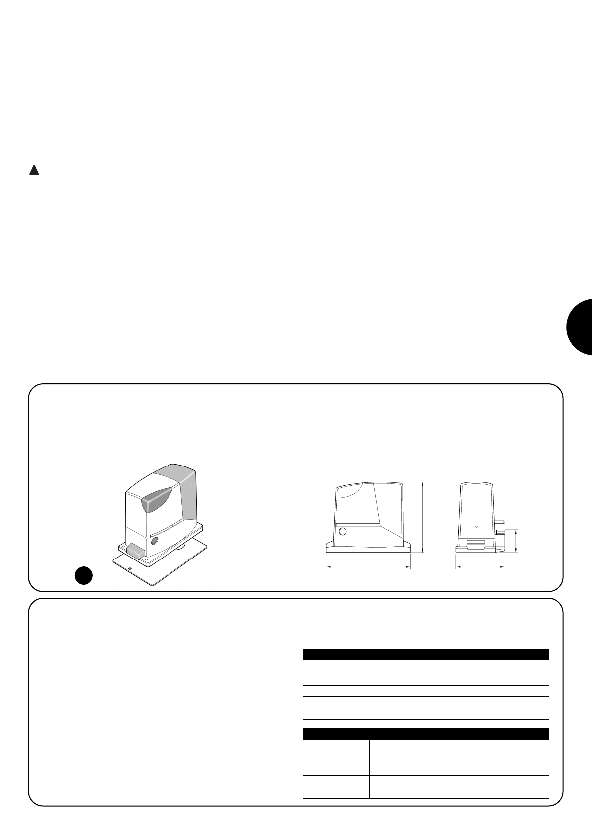
E
91
2.1) Límites de utilización
Los datos referidos a las prestaciones de ROBUS350 están indicados en el capítulo “8 Características técnicas” y son los únicos valores que permiten la evaluación correcta de la idoneidad para su uso.
Generalmente, ROBUS350 es adecuado para automatizar puertas
de hasta 350 kg de peso o de hasta 15 m de largo, según las indicaciones de las tablas N°1 y N°2.
La longitud de la hoja permite determinar la cantidad máxima de
ciclos por hora y de ciclos consecutivos, mientras que el peso permite determinar el porcentaje de reducción de los ciclos y la velocidad máxima admitida; por ejemplo, si la hoja tiene una longitud de
5 m admitiría 10 ciclos/hora y 6 ciclos consecutivos, pero si la hoja
pesa 240 kg hay que reducir los ciclos al 80%, el resultado es 8
ciclos/hora y cerca de 5 ciclos consecutivos, mientras que la velocidad máxima admitida es V5: muy rápida. Para evitar recalentamientos, la central incorpora un limitador que se basa sobre el esfuerzo
del motor y la duración de los ciclos, interviniendo cuando se supera el límite máximo.
Longitud hoja metros
ciclos/hora máximos ciclos consecutivos máximos
Hasta 3 30 20
3÷5 18 12
5÷6 15 10
6÷7 12 8
1) Advertencias
Este manual de instrucciones contiene informaciones importantes en materia de seguridad para la instalación; es necesario leer detenidamente todas
las instrucciones antes de comenzar la instalación. Conserve este manual
en buenas condiciones para su consultación posterior.
Considerando las situaciones de peligro que pueden generarse durante la
instalación y el uso de ROBUS350 es oportuno que también la instalación
sea realizada respetando plenamente las leyes, normas y reglamentos. En
este capítulo se indicarán las advertencias de tipo general; otras advertencias importantes están presentes en los capítulos “3.1 Controles preliminares” y “5 Ensayo y puesta en servicio”.
según la legislación europea más reciente, la realización de
una puerta o cancela automática entra en el ámbito de las disposiciones de la Directiva 98/37/CE (Directiva de Máquinas) y, en
particular, de las normas: EN 12445; EN 12453 y EN 12635 que
permiten declaran la presunción de conformidad.
Más informaciones, directrices para el análisis de los riesgos y para la realización del Expediente Técnico están disponibles en:“www.niceforyou.com”.
• Este manual está destinado exclusivamente a personal técnico cualifica-
do para la instalación. Salvo el anexo específico que el instalador se
encargará de separar, “Instrucciones y advertencias destinadas al usuario
del motorreductor ROBUS”, ninguna de las informaciones aquí incluidas
puede ser de interés para el usuario final.
• Está prohibido utilizar el ROBUS350 con una finalidad diferente de aque-
lla dispuesta en estas instrucciones; un uso inadecuado puede causar
peligros o daños a las personas o bienes.
•
Antes de comenzar la instalación es oportuno efectuar un análisis de los riesgos que incluya la lista de los requisitos esenciales de seguridad previstos en
el anexo I de la Directiva de Máquinas, indicando las soluciones correspondientes adoptadas. Recuérdese que el análisis de los riesgos es uno de los
documentos que forman el “expediente técnico” del automatismo.
•
Compruebe si es necesario incorporar otros dispositivos que puedan servir para
completar el automatismo con ROBUS350 según la situación de empleo específica y los peligros presentes: por ejemplo, deben considerarse los peligros de
impacto, aplastamiento, corte, arrastre, etc. y otros peligros en general.
• No modifique ninguna parte salvo que esté previsto en estas instrucciones; los
trabajos de este tipo pueden causar solamente desperfectos; NICE no es responsable de los daños que deriven de productos modificados.
• Durante la instalación y el uso procure que no puedan entrar elementos
sólidos o líquidos dentro de la central o de otros dispositivos abiertos; de
ser oportuno, diríjase al servicio de asistencia NICE; el uso de ROBUS350
en situaciones análogas puede originar peligros.
• El automatismo no puede utilizarse antes de haberlo puesto en servicio tal
como especificado en el capítulo “5 Ensayo y puesta en servicio”.
• El material de embalaje de ROBUS350 debe eliminarse respetando la normativa local.
• Si el desperfecto no pudiera resolverse utilizando las informaciones indicadas en este manual, diríjase al servicio de asistencia NICE.
• Si se desconectaran los interruptores automáticos o los fusibles, antes de
restablecerlos hay que localizar y eliminar la avería.
• Antes de acceder a los bornes en el interior de la tapa de ROBUS350,
desconecte todos los circuitos de alimentación; si el dispositivo de desconexión no queda a la vista colóquele un cartel que diga “ATENCIÓN
MANTENIMIENTO EN CURSO”.
!
ROBUS350 es un motorreductor electromecánico para mover automáticamente las puertas de corredera para uso residencial, dispone
de una central electrónica de control y de un receptor por radiomando. Las conexiones eléctricas hacia los dispositivos externos
son sencillas gracias a la utilización de “BlueBUS”, una técnica que
permite conectar diversos dispositivos con 2 cables solamente.
El ROBUS350 funciona con energía eléctrica; si esta se cortara, es
posible desbloquear el motorreductor mediante una llave y mover la
puerta manualmente; también es posible utilizar el accesorio opcional: batería compensadora PS124 que permite realizar algunas
maniobras incluso ante el fallo de la alimentación de red.
2) Descripción del producto y uso previsto
Tabla N°1: límites con relación a la longitud de la hoja
Peso hoja kg. Porcentaje ciclos
Velocidad máxima admitida
Hasta 200 100% V6 = Rapidísimo
200÷250 90% V5 = Muy rápido
250÷300 80% V4 = Rápido
300÷350 70% V3 = Medio
Tabla N°2: límites con relación al peso de la hoja
1
330 195
85
277
Page 92
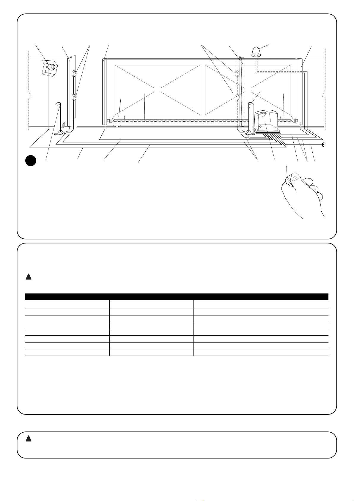
92
2.2) Instalación típica
La figura 1 muestra la instalación típica de la automatización de una puerta de corredera utilizando ROBUS350
2
1 Selector de llave
2 Fotocélulas en columna
3 Fotocélulas
4 Banda neumática principal montada en elemento fijo
(opcional)
5 Banda neumática principal montada en elemento móvil
6 Soportes de fin de carrera “Abierto”
7 Cremallera
8 Banda neumática secundaria montada en elemento
fijo (opcional)
9 Luz intermitente con antena incorporada
10 ROBUS350
11 Soportes de fin de carrera “Cerrado”
12 Banda neumática secundaria montada en elemento
móvil (opcional)
13 Transmisor
2.3) Lista de los cables
En la instalación típica de la figura 1 se indican también los cables necesarios para las conexiones de los diversos dispositivos; en la tabla
N°3 se indican las características de los cables.
Los cables utilizados deben ser adecuados para el tipo de instalación; por ejemplo, se aconseja un cable tipo H03VV-F para
instalación en interiores o bien H07RN-F para instalación en exteriores.
!
Nota 1: si el cable de alimentación mide más de 30 m debe tener una sección más grande, por ejemplo 3x2,5mm2y es necesaria una pues-
ta a tierra de seguridad cerca del automatismo.
Nota 2:si el cable “BLUEBUS” mide más de 30 m, hasta un máximo de 50 m, se necesita un cable de 2x1mm
2
.
Nota 3: los dos cables 2x0,5mm
2
pueden sustituirse con un solo cable 4x0,5mm2.
Nota 4: si se incorpora más de una banda neumática, véase el capítulo “7.3.2 Entrada STOP” para el tipo de conexión aconsejada
Nota 5: para la conexión de las bandas neumáticas montadas en el elemento móvil de la puerta de corredera hay que utilizar dispositivos
oportunos que permitan la conexión también con la hoja en movimiento.
Conexión Tipo de cable Longitud máxima admitida
A: Línea eléctrica de alimentación 1 cable 3x1,5mm
2
30m (nota 1)
B: Luz intermitente con antena
1 cable 2x0,5mm
2
20m
1 cable blindado tipo RG58 20m (aconsejado menos de 5 m)
C: Fotocélulas 1 cable 2x0,5mm
2
30m (nota 2)
D: Selector de llave 2 cables 2x0,5mm2(nota 3) 50m
E: Bandas montadas en elemento fijo 1 cable 2x0,5mm2(nota 4) 30m
F: Bandas montadas en elemento móvil 1 cable 2x0,5mm2 (nota 4) 30m (nota 5)
Tabla N°3: lista de los cables
La instalación de ROBUS350 debe ser efectuada por personal cualificado, respetando las leyes, normas y reglamentos y las
indicaciones de las presentes instrucciones.
!
3) Instalación
2
43 38
10
2
6
11
7
9
13
1251
EF
D
C F
A
B
Page 93

E
93
3.2) Fijación del motorreductor
Si ya existe la superficie de apoyo, el motorreductor se fija directamente sobre la superficie utilizando medios adecuados, por ejemplo
tacos de expansión. Por el contrario, para fijar el motorreductor:
1. Efectúe un pozo para una cimentación de dimensiones adecuadas, utilizando como referencia las cotas indicadas en la Figura 3.
2. Haga llegar uno o varios tubos para que pasen los cables eléctricos, como muestra la Figura 4.
3. Ensamble las dos grapas en la placa de cimentación colocando
una tuerca abajo y una arriba de la placa; la tuerca debajo de la placa se enrosca hasta el fondo de la rosca a fin de que la parte roscada sobresalga en torno a 25÷35 mm por encima de la placa.
4. Haga la colada de hormigón y, antes de que comience a fraguar,
coloque la placa de cimentación según las cotas indicadas en la
figura 3; compruebe que quede paralela a la hoja y perfectamente nivelada. Espere el fin de fraguado del hormigón.
5. Quite las 2 tuercas superiores de la placa y apoye el motorreductor; compruebe que quede perfectamente paralelo respecto
de la hoja y después enrosque ligeramente las 2 tuercas y arandelas entregadas, como muestra la figura 7.
3.1) Controles preliminares
Antes de comenzar con la instalación de ROBUS350 es necesario
efectuar los siguientes controles:
• Controle que todo el material a utilizar esté en perfecto estado,
sea adecuado para su uso y que respete las normas.
• Controle que la estructura de la puerta sea adecuada para su
automatización.
• Controle que el peso y las dimensiones de la hoja respeten los límites de utilización indicados en el capítulo “2.1 Límites de utilización”
• Controle, comparando con los valores indicados en el capítulo “8
Características técnicas”, que la fricción estática (es decir la fuerza necesaria para poner en movimiento la hoja) sea inferior a la
mitad del “Par máximo” y que la fricción dinámica (es decir la fuerza necesaria para mantener la hoja en movimiento) sea inferior a
la mitad del “Par nominal”; se aconseja un margen del 50% en las
fuerzas porque las condiciones climáticas adversas pueden
aumentar las fricciones.
• Controle que en toda la carrera de la puerta, tanto de cierre como
de apertura, no haya puntos de mayor fricción.
• Controle que no exista el peligro de que la hoja se descarrile y que
no se pueda salir de las guías
• Controle la robustez de los topes mecánicos de sobrerrecorrido,
controlando que no se produzcan deformaciones tampoco si la
puerta golpeara con fuerza contra el tope.
• Controle que la puerta esté bien equilibrada, es decir que no se
mueva al dejarla detenida en cualquier posición.
• Controle que la zona de fijación del motorreductor no pueda inundarse; de ser oportuno, monte el motorreductor levantado del piso.
• Controle que la zona de fijación del motorreductor permita el desbloqueo y una maniobra manual fácil y segura.
• Controle que los puntos de fijación de los distintos dispositivos se
encuentren en zonas protegidas de choques y que las superficies
sean suficientemente firmes.
• Evite que los componentes del automatismo puedan quedar
sumergidos en agua o en otras substancias líquidas.
• No coloque ROBUS350 cerca de llamas o fuentes de calor, en
atmósferas con riesgo de explosión, muy ácidas o salinas, porque
ROBUS350 podría arruinarse y tener problemas de funcionamiento o generar situaciones de peligro.
• Si hubiera un portillón de paso en la misma hoja o una puerta en
la zona de movimiento de la hoja, asegúrese de que no obstaculice la carrera normal e incorpore un sistema de interbloqueo oportuno en su caso
• Conecte la central a una línea de alimentación eléctrica dotada de
puesta a tierra de seguridad.
• La línea de alimentación eléctrica debe estar protegida por un dispositivo magnetotérmico y diferencial adecuado.
• En la línea de alimentación de la red eléctrica hay que montar un
dispositivo de desconexión de la alimentación (con categoría de
sobretensión III es decir distancia entre los contactos de 3,5 mm
como mínimo) u otro sistema equivalente, por ejemplo una toma y
una clavija. Si el dispositivo de desconexión de la alimentación no
está cerca del automatismo, coloque un sistema de bloqueo a fin
de evitar la conexión accidental o no autorizada.
3
4
5
6
192
330 0÷50
0÷50 330
192
0÷10
0÷10
25÷35
7
Page 94

94
3.3) Instalación de los diferentes dispositivos
Instale los demás dispositivos siguiendo las instrucciones correspondientes. Controle en el párrafo “3.5 Descripción de las conexiones eléctricas” y en la figura 1, los dispositivos que pueden conectarse a ROBUS350.
Para evitar que el peso de la puerta pueda cargar sobre
el motorreductor, es importante que entre la cremallera y
el piñón haya un juego de 1÷2 mm tal como muestra la
figura 10.
8. Haga deslizar la hoja y utilice siempre el piñón como referencia
para fijar los demás elementos de la cremallera.
9. Corte la parte excedente del último tramo de la cremallera.
10.Realice varias maniobras de apertura y cierre, comprobando que
la cremallera se deslice alineada al piñón con una desalineación
máxima de 5 mm y que a todo lo largo se haya respetado un juego de 1÷2 mm entre el piñón y la cremallera.
11. Apriete con fuerza las tuercas de fijación del motorreductor a fin
de que quede fijado firmemente al piso; cubra las tuercas de fijación con las tapas correspondientes, figura 11.
12.Fije con los tornillos sin cabeza correspondientes los soportes
de fin de carrera de “Apertura” y de “Cierre” en los extremos de
la cremallera, véase figura 12. Considere que cuando se activan
los fines de carrera, la puerta se moverá otros 2÷3 cm; por lo
que se aconseja colocar los soportes del fin de carrera dejando
un margen oportuno respecto de los topes mecánicos.
13.Bloquee el motorreductor tal como indicado en el párrafo “Desbloqueo y movimiento manual” en el capítulo “Instrucciones y
advertencias destinadas al usuario del motorreductor ROBUS”.
!
8 9
10
11 12
Si la cremallera está instalada, una vez fijado el motorreductor, ajuste los pasadores de regulación, como muestra la figura 8 para colocar el piñón de ROBUS350 a la altura justa dejando 1÷2 mm de juego desde la cremallera. Por el contrario, para fijar la cremallera:
6. Desbloquee el motorreductor tal como indicado en el párrafo
“Desbloqueo y movimiento manual” en el capítulo “Instrucciones
y advertencias destinadas al usuario del motorreductor ROBUS”.
7. Abra completamente la puerta, apoye sobre el piñón el primer
tramo de cremallera y controle que el comienzo de la cremallera
corresponda al comienzo de la puerta, tal como muestra la figura 9. Controle que entre el piñón y la cremallera haya un juego de
1÷2 mm, después fije la cremallera en la hoja utilizando los elementos adecuados.
1÷2
3.4) Conexiones eléctricas
Todas las conexiones eléctricas se deben efectuar sin
tensión en la instalación y, en su caso, con la batería compensadora desconectada.
1. Para desmontar la tapa de protección y acceder a la central elec-
trónica de control de ROBUS350 quite el tornillo del costado y
extraiga la tapa tirando de ella hacia arriba.
2.Quite la membrana de goma que cierra el agujero para la entrada
de los cables e introduzca todos los cables de conexión hacia los
distintos dispositivos, dejándolos 20÷30 cm más largos de lo
necesario. Véase la tabla N°3 para el tipo de cable y la figura 1
para las conexiones.
3. Con una brida reúna todos los cables que entran en el motorre-
ductor, y colóquela un poco más abajo del agujero de entrada de
los cables. En la membrana de goma corte un agujero un poco
más estrecho que el diámetro de los cables recogidos e introduzca la membrana a lo largo de los cables hasta la brida; entonces, vuelva a colocar la membrana en el alojamiento del agujero
para el paso de los cables. Coloque otra brida para recoger los
cables un poco más arriba de la membrana.
4. Conecte el cable de alimentación en el borne correspondiente,
como muestra la figura 13 y con una brida bloquee el cable en el
primer anillo sujetacable.
5. Conecte los demás cables según el esquema de la figura 15 Para
una mayor comodidad, los bornes pueden extraerse.
6. Una vez concluidas las conexiones, bloquee con bridas los
cables reunidos en el segundo anillo sujetacables, la parte sobrante del cable de la antena se bloquea a los demás cables con
otra brida como muestra la figura 14.
!
Page 95

E
95
3.5) Descripción de las conexiones eléctricas
En este párrafo hay una breve descripción de las conexiones eléctricas; otras informaciones en el párrafo “7.3 Instalación y desinstalación de dispositivos”.
FLASH: salida para la luz intermitente “LUCYB” o similar sólo con la
bombilla de 12V máximo 21W.
S.C.A.: salida “Indicador Luminoso Cancela Abierta”; es posible
conectar una bombilla de 24V, máximo 4W
BLUEBUS: en este borne se pueden conectar los dispositivos
compatibles; todos se conectan en paralelo con dos conductores
solos por los que transita tanto la alimentación eléctrica como las
señales de comunicación. Para más informaciones sobre BlueBUS
véase el párrafo “7.3.1BlueBUS”.
STOP: entrada para los dispositivos que bloquean o detienen la
maniobra que se está ejecutando; con soluciones oportunas pueden conectarse en la entrada contactos tipo “Normalmente Cerrado”, “Normalmente Abierto” o dispositivos de resistencia constante.
Para más informaciones sobre STOP véase el párrafo “7.3.2 Entrada STOP”.
P. P.: entrada para dispositivos que controlan el movimiento; es posible conectar contactos tipo “Normalmente Abierto”.
ANTENNA: entrada de conexión de la antena para receptor (la
antena está incorporada en LUCY B).
13
14
15
Antes de comenzar el control y de poner en marcha la automatización, se aconseja colocar la puerta en la mitad de su carrera para que
pueda abrirse o cerrarse libremente.
4) Controles finales y puesta en marcha
4.1) Selección de la dirección
De acuerdo con la posición del motorreductor respecto de la puerta, es necesario elegir la dirección de la maniobra de apertura; si
para abrirse la hoja debe moverse hacia la izquierda, desplace el
selector hacia la izquierda, tal como indicado en la figura 16, si para
abrirse la puerta debe moverse hacia la derecha, coloque el selector
hacia la derecha, tal como indicado en la figura 17.
16
17
LUCYB S.C.A. MOFB MOSE
Page 96

96
Ni bien se conecta la tensión a ROBUS350, se aconseja realizar
algunos controles sencillos:
1. Controle que el led BLUEBUS destelle regularmente con una frecuencia de un destello por segundo.
2. Controle que también destellen los leds de las fotocélulas (tanto
en TX como en RX); no es importante el tipo de destello, depende de otros factores.
3. Controle que la luz intermitente conectada a la salida FLASH y la
luz indicadora conectada a la salida S.C.A. estén apagadas
Si así no fuera, se aconseja apagar inmediatamente la alimentación de
la central y controlar con mayor atención las conexiones eléctricas.
Otras informaciones útiles para la búsqueda y el diagnóstico de las
averías se encuentran en el capítulo “7.6 Solución de los problemas”
4.2) Conexión de la alimentación
La conexión de la alimentación a ROBUS350 debe ser hecha por personal técnico experto y cualificado que posea los requisitos exigidos
y respetando las normas, leyes y reglamentos.
!
4.3) Aprendizaje de los dispositivos
Después de concluir la conexión de la alimentación, hay que hacer
que la central reconozca los dispositivos conectados en las entradas
BLUEBUS y STOP. Antes de esta etapa los leds L1 y L2 destellan
indicando que se ha de efectuar el aprendizaje de los dispositivos.
La etapa de aprendizaje de los dispositivos conectados puede repetirse en cualquier momento, incluso
después de la instalación, por ejemplo si se añade un dispositivo; para efectuar un nuevo aprendizaje, véase
el párrafo “7.3.4 Aprendizaje de otros dispositivos”.
1. Presione y mantenga presionados los dos botones [▲] y [Set]
2.
Suelte los botones cuando los leds L1 y L2 comiencen a destellar muy rápidamente (transcurridos alrededor de 3s)
3. Espere algunos segundos a que la central concluya el aprendizaje de los dispositivos.
4. Al concluir el aprendizaje, el led STOP debe quedar encendido y los leds L1 y L2 se apagarán (podrían comen-
zar a destellar los leds L3 y L4).
4.4) Aprendizaje de la longitud de la puerta
Después del aprendizaje de los dispositivos comenzarán a destellar
los leds L3 y L4; esto significa que es necesario que la central reconozca la longitud de la puerta (distancia desde el fin de carrera de
cierre al fin de carrera de apertura); dicha medida es necesaria para
calcular los puntos de deceleración y el punto de apertura parcial.
Si así no fuera, se aconseja apagar inmediatamente la alimentación de la central y controlar con mayor atención las conexiones eléctricas. Otras informaciones útiles se encuentran en el capítulo “7.6 Solución de los
problemas”.
1. Presione y mantenga presionados los botones [▼] y [Set]
2. Suelte los botones cuando comience la maniobra (transcurridos unos 3s)
3. Controle que la maniobra sea una apertura, por el contrario presione el botón [Stop] y lea con mayor atención
el párrafo “4.1 Selección de la dirección”; entonces repita desde el punto 1.
4. Espere a que la central complete la maniobra de apertura hasta llegar al fin de carrera de apertura; inmediatamente después comienza la maniobra de cierre.
5. Espere a que la central complete la maniobra de cierre.
4.5) Control del movimiento de la puerta
Después del aprendizaje de la longitud de la puerta se aconseja
efectuar algunas maniobras para verificar el movimiento correcto de
la puerta.
1. Presione el botón [Open] para accionar una maniobra de “Abrir”;
controle que la puerta se abra normalmente sin cambios de velocidad; solamente cuando la puerta está entre 70 y 50 cm del fin de
carrera de apertura deberá desacelerar y detenerse, por la activación del fin de carrera, a 2÷3 cm del tope mecánico de apertura.
2. Presione el botón [Close] para accionar una maniobra de “Cerrar”;
controle que la puerta se cierre normalmente sin cambios de velocidad; solamente cuando la puerta está entre 70 y 50 cm del fin de
carrera de cierre deberá desacelerar y detenerse, por la activación
del fin de carrera, a 2÷3 cm del tope mecánico de cierre.
3. Durante las maniobras controle que la luz intermitente destelle
con intervalos de 0,5s encendido y 0,5s apagado. En su caso,
controle también los destellos de la luz indicadora conectada al
borne SCA: destello lento en apertura y rápido en el cierre.
4. Cumpla varias maniobras de apertura y cierre a fin de observar
posibles defectos de montaje y de regulación u otras irregularidades, por ejemplo los puntos con mayor roce.
5. Controle que la fijación del motorreductor ROBUS350, de la cremallera y de los soportes de fin de carrera sean firmes, estables
y adecuadamente resistentes también durante las aceleraciones
o deceleraciones violentas del movimiento de la puerta
4.6) Funciones predeterminadas
La central de control de ROBUS350 dispone de algunas funciones
programables; tales funciones se regulan en fabrica con una configuración que debería satisfacer la mayoría de las automatizaciones,
sin embargo las funciones pueden modificarse en cualquier momento
mediante un procedimiento de programación oportuno; a tal fin véase el párrafo “7.2 Programaciones”.
18
19
Page 97
E
97
N°1 Mando “PP”
N°2 Mando “Apertura paso de peatones”
N°3 Mando “Abrir”
N°4 Mando “Cerrar”
Tabla N°5: mandos disponibles en Modo II
4.7) Memorización de los transmisores
Para el accionamiento a distancia de ROBUS350, la central de control incorpora el enchufe SM para receptores tipo SMXI o SMXIS (véase
fig.20); cada transmisor es reconocido por este receptor mediante un "código" que es diferente de cualquier otro. Por tal razón, se requiere una etapa de "memorización" con la que se prepara el receptor para reconocer cada transmisor; los transmisores se pueden memorizar
en dos modos.
Modo I: en este modo la función de los botones del transmisor es
fija y a cada botón corresponde en la central el mando indicado en
la tabla N°4; se lleva a cabo una sola etapa para cada transmisor del
que se memorizan todos los botones; durante esta fase no interesa
qué botón se tiene presionado y se ocupa un solo espacio en la
memoria. Por lo general, en modo I, un transmisor puede accionar
un automatismo solo
Modo II: en este modo cada botón del transmisor puede asociarse
a uno de los 4 mandos posibles de la central indicados en la tabla
N°5; para cada fase se memoriza un botón solo, es decir aquel presionado durante la memorización. En la memoria se ocupa un lugar
por cada botón memorizado.
En el modo II los diversos botones del mismo transmisor pueden utilizarse para dar órdenes a la misma automatización o para accionar
diversas automatizaciones. Por ejemplo en la tabla N° 6 se acciona
sólo la automatización “A” y los botones T3 y T4 están asociados al
mismo mando; o bien, en el ejemplo de la tabla 7 donde se accionan 3 automatizaciones “A” (botones T1 y T2), “B” (botón T3) y “C”
(botón T4)
Puesto que el procedimiento de memorización cuenta con
un tiempo límite de 10s, es necesario leer antes las instrucciones indicadas en los siguientes párrafos y luego ejecutarlas.
!
Botón T1 Mando “PP”
Botón T2 Mando "Apertura paso de peatones"
Botón T3 Mando “Abrir”
Botón T4 Mando “Cerrar”
Tabla N°4: memorización Modo I
Botón T1 Mando “Abrir” Automatización A
Botón T2 Mando “Cerrar” Automatización A
Botón T3 Mando “Apertura paso peatones” Automatización A
Botón T4 Mando “Apertura paso peatones” Automatización A
Tabla N°6: 1° ejemplo de memorización en Modo II
Botón T1 Mando “Abrir” Automatización A
Botón T2 Mando “Cerrar” Automatización A
Botón T3 Mando “PP” Automatización B
Botón T4 Mando “PP” Automatización C
Tabla N°7: 2° ejemplo de memorización en Modo II
Nota: los transmisores monocanal disponen del botón T1 solo, los transmisores bicanal disponen de los botones T1 y T2 solos.
1. Presione y mantenga presionado el botón en el receptor (durante unos 3s)
3s
2. Suelte el botón cuando se encienda el led del receptor
3. Antes de 10s presione durante 2s cualquier botón del transmisor que se ha de memorizar
2s
4. Si la memorización se ha ejecutado correctamente, el led en el receptor emitirá 3 destellos.
x3
Si hubiera otros transmisores a memorizar, repita el punto 3 dentro de los 10s siguientes. La memorización termina automáticamente si
durante 10 segundos no se reciben códigos nuevos.
Tabla N° 8: para memorizar un transmisor en modo I. Ejemplo
4.7.1) Memorización en modo I
1. Presione el botón del receptor una cantidad de veces equivalente al mando deseado,
según la tabla N°5 1....4
2. Controle que el led del receptor emita una cantidad de destellos equivalente al mando deseado
1....4
3. Antes de 10s, presione durante 2s el botón deseado del transmisor que se ha de memorizar
2s
4. Si la memorización se ha ejecutado correctamente, el led en el receptor emitirá 3 destellos.
x3
Si hubiera otros transmisores a memorizar para el mismo mando, repita el punto 3 dentro de los 10s siguientes. La memorización termina
automáticamente si durante 10 segundos no se reciben códigos nuevos.
Tabla N° 9: para memorizar el botón de un transmisor en modo II. Ejemplo
4.7.2) Memorización en modo II
20
Page 98
98
I
1. Presione durante 5s como mínimo el botón en el nuevo transmisor; después suéltelo.
5s
2. Presione lentamente 3 veces el botón en el transmisor memorizado
1s 1s 1s
3. Presione lentamente 1 vez el botón en el transmisor nuevo.
1s
Ahora el nuevo transmisor será reconocido por el receptor y adquirirá las características que tenía el que ya estaba memorizado. Si
hubiera que memorizar otros transmisores, repita todos los pasos para cada transmisor nuevo.
Tabla N°10: para memorizar un transmisor a distancia. Ejemplo
4.7.3) Memorización a distancia
Es posible memorizar un nuevo transmisor sin tener que utilizar
directamente el botón del receptor; a tal fin es necesario tener un
telemando memorizado y que funcione. El nuevo transmisor “heredará” las características del que ya está memorizado; es decir que
si el primer transmisor está memorizado en Modo 1, también el nuevo transmisor se memorizará en Modo 1 y se podrá presionar cualesquiera de los botones de los transmisores. Por el contrario, si el
primer transmisor está memorizado en Modo II, también el nuevo
transmisor se memorizará en Modo II y es importante presionar, en
el primer transmisor el botón relativo al mando deseado, y en el
segundo transmisor el botón a asociar a ese mando.
La memorización a distancia puede realizarse en todos
los receptores que se encuentran en el radio de alcance
del transmisor y, por eso, es oportuno mantener alimentado sólo aquel que debe memorizarse.
!
1. Presione y mantenga presionado el botón en el receptor
2.
Espere a que el led se encienda, se apague y que emita 3 destellos.
x3
3. Suelte el botón exactamente durante el 3° destello.
4. Si el procedimiento se concluye correctamente, transcurrido un instante, el led emitirá 5 destellos.
x5
Tabla N°11: para borrar todos los transmisores Ejemplo
4.7.4) Borrado de los transmisores
Declaración de conformidad
N°: 151/SMXI Rev03
Nice S.p.a., Via Pezza Alta 13, 31046 Rustignè di Oderzo (TV) Italia
NICE S.p.a. declara que los receptores modelo SMXI, SMXIS y los transmisores FLO2R-S y SM2 correspondientes responden a los requisitos esenciales de la Directiva R&TTE 1999/5/CE, para el uso previsto del aparato. Fabricado en Clase 1, Sub-clase 20
Fecha: 19 Marzo 2004 Director
Lauro Buoro
4.7.5) Declaración de conformidad del receptor
Esta es la etapa más importante de la realización del automatismo a
fin de garantizar su máxima seguridad. El ensayo también puede
usarse como control periódico de los dispositivos que componen el
automatismo.
El ensayo de toda la instalación debe ser efectuado por
personal cualificado y experto que deberá establecer los
ensayos previstos de acuerdo con los riesgos presentes y
controlar que se respeten las leyes, normativas y reglamentos, especialmente todos los requisitos de la norma
EN 12445 que establece los métodos de ensayo de los
automatismos para puertas.
!
5) Ensayo y puesta en servicio
Con los dos transmisores situados en el radio de acción del automatismo, lleve a cabo los siguientes pasos:
Page 99

E
99
5.1) Ensayo
Cada componente del automatismo, por ejemplo bandas neumáticas, fotocélulas, parada de emergencia, etc., exige un fase de ensayo específica; por dicha razón se deberán seguir los diferentes procedimientos indicados en los manuales de instrucciones respectivos. Para el ensayo del ROBUS350 ejecute la siguiente secuencia
de operaciones:
1. Controle que hayan sido respetadas estrictamente las indicacio-
nes dadas en este manual y especialmente aquellas del capítulo
“1 Advertencias”;
2. Desbloquee el motorreductor tal como indicado en el párrafo
“Desbloqueo y movimiento manual” en el capítulo “Instrucciones
y advertencias para el usuario del motorreductor ROBUS350”.
3. Controle que sea posible abrir y cerrar manualmente la puerta con
una fuerza que no supere 390N (alrededor de 40kg).
4. Bloqueo del motorreductor.
5. Utilizando los dispositivos de mando o de parada previstos (selec-
tor de llave, botones de mando o transmisores), efectúe ensayos
de apertura, cierre y parada de la puerta y compruebe que el
comportamiento sea el previsto.
6. Controle uno por uno el funcionamiento correcto de todos los dispositivos de seguridad incorporados en la instalación (fotocélulas,
bandas sensibles, parada de emergencia, etc.), comprobando
que el comportamiento de la puerta corresponda al previsto.
Cada vez que un dispositivo se acciona, el led “BlueBUS” en la
central debe emitir 2 destellos más rápidos, confirmando que la
central reconoce el evento.
7. Si las situaciones peligrosas causadas por el movimiento de la
puerta se han prevenido limitando la fuerza de impacto, hay que
medir la fuerza de acuerdo con la disposición de la norma EN
12445. Si la regulación de la “Velocidad” y el control de la “Fuerza del motor” se usan como una ayuda del sistema para reducir
la fuerza de impacto, pruebe y busque la regulación que dé los
mejores resultados.
5.2) Puesta en servicio
La puesta en servicio puede llevarse a cabo sólo después de haber
efectuado correctamente todas las etapas de ensayo del
ROBUS350 y de los demás dispositivos montados.
Está prohibida la puesta en servicio parcial o en situaciones “provisionales”.
1. Realice y conserve durante 10 años como mínimo el expediente
técnico de la automatización que deberá estar formado de los
siguientes componentes como mínimo: dibujo de conjunto de la
automatización, esquema de las conexiones eléctricas, análisis
de los riesgos y soluciones adoptadas, declaración de conformidad del fabricante de todos los dispositivos utilizados (para
ROBUS350 utilice la Declaración de conformidad CE adjunta);
copia del manual de instrucciones de uso y del plan de mantenimiento del automatismo.
2. Aplique a la puerta una placa con los siguientes datos: tipo de
automatización, nombre y dirección del fabricante (responsable
de la “puesta en servicio”), número de matrícula, año de fabricación y marcado “CE”.
3. Fije de forma permanente en proximidad de la puerta una etiqueta o una placa que indique las operaciones para el desbloqueo y
la maniobra manual
4. Realice y entregue al dueño la declaración de conformidad CE de
la automatización.
5. Realice y entregue al dueño el “manual de instrucciones y advertencias para el uso de la automatización”.
6. Realice y entregue al dueño el plan de mantenimiento de la automatización (que debe incluir todas las prescripciones sobre el
mantenimiento de cada dispositivo).
7. Antes de poner en funcionamiento la automatización, informe
adecuadamente y por escrito al dueño (por ejemplo en el manual
de instrucciones y advertencias para el uso de la automatización)
acerca de los peligros y los riesgos presentes.
En este capítulo se mencionan las informaciones para realizar el plan de mantenimiento y el desguace de ROBUS350
6) Mantenimiento y desguace
6.1) Mantenimiento
Para mantener el nivel de seguridad constante y para garantizar la
duración máxima de toda la automatización, es necesario efectuar
un mantenimiento regular.
El mantenimiento debe efectuarse respetando las
prescripciones de seguridad de este manual y según las
leyes y normativas vigentes.
Para los demás dispositivos diferentes de ROBUS350 siga las instrucciones mencionadas en los planes de mantenimiento correspondientes.
1. ROBUS350 requiere un mantenimiento programado antes de trans-
curridos 6 meses como máximo o 10.000 maniobras a partir delmantenimiento anterior:
2. Desconecte cualquier fuente de alimentación eléctrica, incluidas
las baterías compensadoras
3. Controle las condiciones de todos los materiales que componen
la automatización, controlando especialmente los fenómenos de
corrosión y oxidación de las piezas de la estructura; sustituya las
piezas que no sean seguras.
4. Controle el desgaste de las piezas en movimiento: piñón, cremallera y todas las piezas de la hoja, sustituya las piezas gastadas.
5. Conecte las fuentes de alimentación eléctrica y ejecute todos los
ensayos y controles previstos en el párrafo “5.1 Ensayo”.
!
6.2) Desguace
ROBUS está formado de varios tipos de materiales, algunos de los
cuales pueden reciclarse; acero, aluminio, plástico, cables eléctricos; otros deberán ser eliminados: baterías y tarjetas electrónicas.
Algunos componentes electrónicos y las baterías
podrían contener substancias contaminantes; no los
abandone en el medio ambiente. Infórmese sobre los sistemas de reciclaje o eliminación respetando las normas
vigentes locales.
1. Desconecte la alimentación eléctrica de la automatización y la
batería compensadora de estar montada.
2. Desmonte todos los dispositivos y accesorios, siguiendo el procedimiento en el orden inverso a aquel descrito en el capítulo 3
“Instalación”.
3. Separe dentro de lo posible las partes que puedan o deban ser
recicladas o eliminadas de otro modo, por ejemplo las piezas
metálicas de aquellas de plástico, las tarjetas electrónicas, baterías, etc.
4. Separe y entregue los materiales a las empresas autorizadas para
la recuperación y eliminación de residuos.
!
Page 100
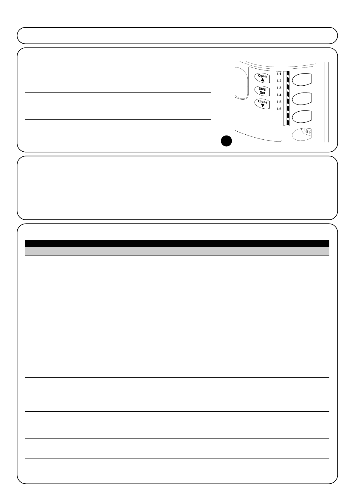
100
Led Función Descripción
L1 Cierre automático
Esta función permite un cierre automático de la puerta después del tiempo de pausa programado, el Tiempo
Pausa de fábrica está configurado en 30 segundos, pero puede modificarse en 5, 15, 30, 45, 60 y 80
segundos. Si la función está desactivada, el funcionamiento es “semiautomático”.
L2 Cerrar Después de Esta función permite tener la puerta abierta solo durante el tiempo necesario para el tránsito, en efecto,
Fotocélula la activación de "Foto" provoca siempre un cierre automático con un tiempo de pausa de 5s
(independientemente del valor programado).
El comportamiento cambia según si se activa o no la función de "Cierre Automático".
Con "Cierre Automático" desactivado: la puerta siempre alcanza la posición de apertura total (aunque
si la Fotocélula queda descubierta antes). Al quedar la fotocélula descubierta se provoca el cierre
automático con una pausa 5s.
Con “Cierre Automático” activo: la maniobra de apertura se detiene inmediatamente después de que
las fotocélulas quedan descubiertas y, transcurridos 5 seg, comenzará la maniobra de cierre.
La función "Cerrar después de Fotocélula" siempre se deshabilita en las maniobras interrumpidas por un
mando de Stop. Si la función "Cerrar después de fotocélula" no está activa el tiempo de pausa será
aquel programado, o no se producirá el cierre automático si la función no está activa.
L3 Cerrar Siempre La función “Cerrar Siempre” se activa provocando un cierre cuando al volver la alimentación se detecta
que la puerta está abierta. Por motivos de seguridad, la maniobra es antecedida de 5s de destello
previo. Si la función está desactivada, al volver la alimentación la puerta quedará detenida.
L4 Stand-By Esta función permite reducir al máximo los consumos; es útil durante el funcionamiento con la batería
compensadora. Si esta función está activa, después de 1 minuto del final de la maniobra, la central
apaga la salida BLUEBUS (y luego los dispositivos) y todos los leds, salvo el led BLUEBUS que
destellará más lentamente. Cuando llegue un mando, la central reanuda el funcionamiento. Si la función
está desactivada, los consumos no disminuirán.
L5 Punto de arranque Activando esta función se desactiva la aceleración gradual y cualquier inicio de maniobra; permite
obtener la fuerza del punto de arranque máxima y es útil donde existen elevadas fricciones estáticas, por
ejemplo en caso de nieve o hielo que bloqueen la puerta. Si el punto de arranque está desactivado, la
maniobra empieza con una aceleración gradual.
L6 Destello previo Con la función de destello previo se añade una pausa de 3s entre el encendido de la luz intermitente y el
inicio de la maniobra para advertir anticipadamente de la situación de peligro. Si el destello previo está
desactivado, el encendido de la luz intermitente coincide con el comienzo de la maniobra.
Durante el funcionamiento normal de ROBUS350 los leds L1….L6 están encendidos o apagados de acuerdo con el estado de la función
que estos representan, por ejemplo L1 está encendido si la función “Cierre automático” está activa.”.
En este capítulo se tratarán las posibilidades de programación, personalización, diagnóstico y búsqueda de las averías sobre ROBUS350.
7) Otras informaciones
Open El botón “OPEN” permite accionar la apertura de la puerta
▲ o desplazar hacia arriba el punto de programación
Stop El botón “STOP” permite detener la maniobra; al presionarlo
Set durante más de 5 segundos, permite entrar en programación.
Close El botón “CLOSE” permite accionar el cierre de la puerta o desplazar
▼ hacia abajo el punto de programación
7.1) Botones de programación
En la central de control de ROBUS350 hay 3 botones que pueden
utilizarse para el accionamiento de la central durante los ensayos o
para las programaciones:
7.2) Programaciones
En la central de control de ROBUS350 hay algunas funciones programables; las funciones se regulan con los 3 botones situados en
la central: [▲] [Set] [▼] y se visualizan a través de los 6 leds:
L1…L6.
Las funciones programables disponibles en ROBUS350 están
dispuestas en 2 niveles:
Primer nivel: funciones regulables en modo ON-OFF (activo o
desactivado); en este caso, cada led L1…L6 indica una función; si
está encendido, la función está activa, si está apagado, la función
está desactivada; véase la tabla N°12.
Segundo nivel: parámetros regulables en una escala de valores
(valores de 1 a 6); en este caso cada led L1…L6 indica el valor
regulado entre los 6 valores posibles; véase la tabla N°14.
Tabla N°12: lista de las funciones programables: primer nivel
7.2.1) Funciones de primer nivel (funciones ON-OFF)
21
 Loading...