

Page 1
control units
robo, thor
Istruzioni ed avvertenze per l’installatore
Instructions and warnings for the fitter
Instructions et recommandations pour l’installateur
Anweisungen und Hinweise für den Installateur
Instrucciones y advertencias para el instalador
Instrukcje i uwagi dla instalatora
Page 2

robo
Page 3

GB
I
F
D
E
PL
thor
GB
I
F
D
E
PL
Page 4
4
control unit
gearmotors
robo, thor
Warnings:
This manual has been especially written for use by
qualified fitters. No information given in this manual can be
considered as being of interest to end users!
The control unit has been designed to control electromechanical actuators for automated swing gates ar doors;
any other use is considered improper and is consequently
forbidden by current laws.
Do not install the unit before you have read all the instructions at least
once.
!
Table of contents: page
1 Description of the product 5
2 Installation 5
2.1 Typical system layout 5
2.2 Electrical connections 6
2.2.1 Electrical diagram 6
2.2.2 Description of connections 6
2.2.3 Phototest 7
2.2.4 Checking connections 8
3 Adjustments 8
4 Testing 9
5 Operating modes 10
page
6 Programmable functions 10
6.1 Description of functions 11
7 How to... 12
8 Accessories 13
9 Maintenance 13
10 Disposal 13
11 What to do if... 13
12 Technical specifications 13
Page 5
GB
5
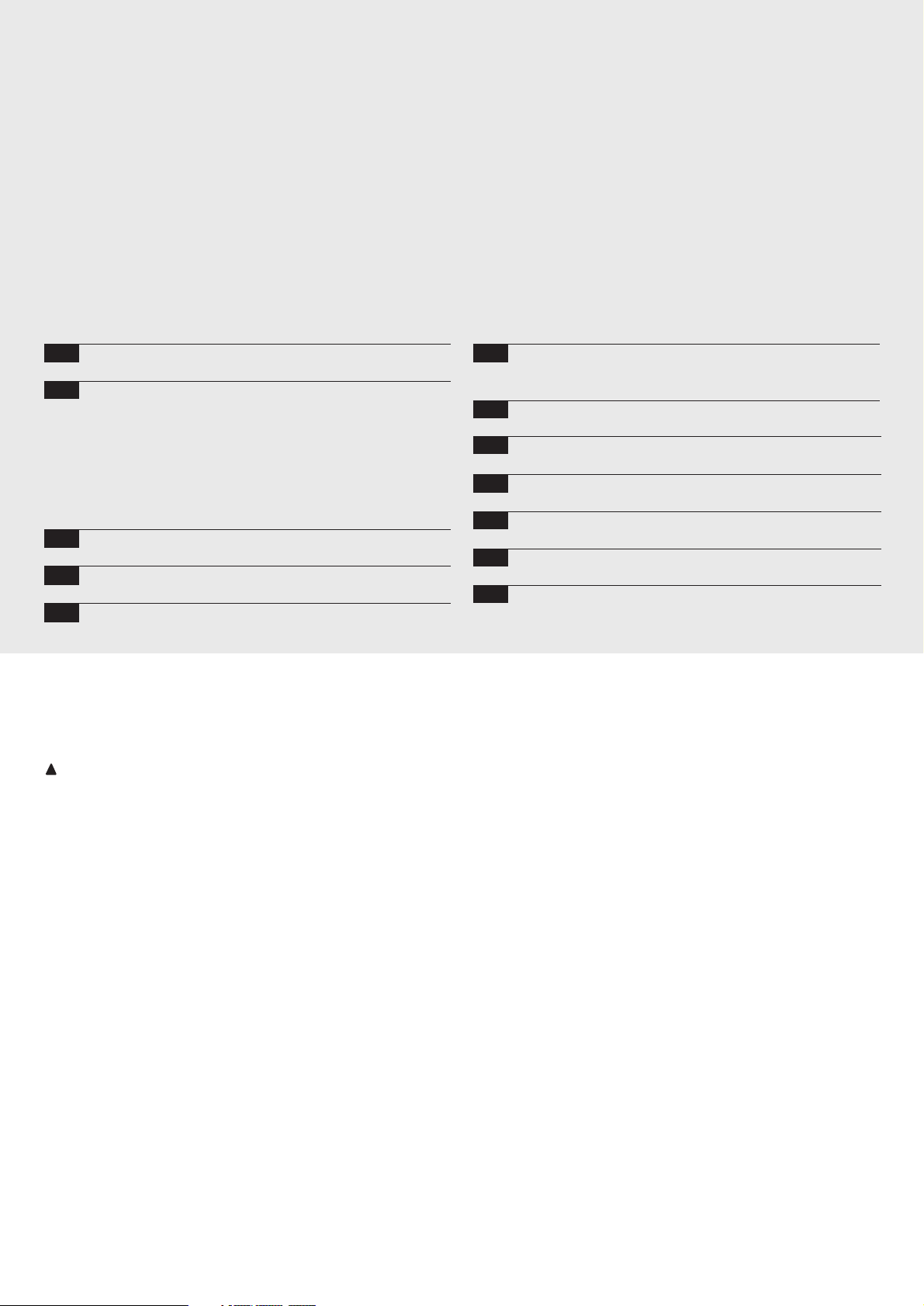
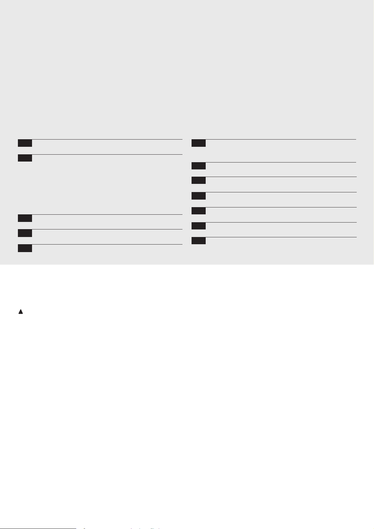
1) Description of the product:
This gate and door automation unit controls gearmotors with singlephase alternating current.
It also features a series of functions that can be selected by DipSwitch (mini-switches) and adjustments performed by Trimmers.
The control unit features input status Led’s located near such inputs,
while another Led near the microprocessor indicates that the internal
logic works correctly.
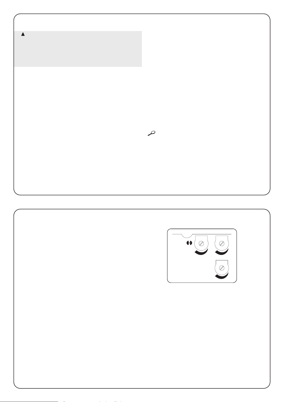
To make it easier to recognise the various parts, fig.1 shows the
main components.
OK
BAC
R
D E
F
G
H
I
L
M
P
S
Z
O
T
U V
Q
N
W
X
Terminal board for aerial
Function selection Dip-Switch
Step by step button
Working Time TL adjustment trimmer
Pause Time Tp adjustment Trimmer
Input/output control terminal board
Limit switch input connector
Flashing light / courtesy light output terminal board.
Capacitor Connector
Motor power output connector
Power input terminal board
Courtesy light mode selector
Radio slot
Microprocessor
Low voltage rapid fuse (315mA F)
Force adjustment trimmer (F)
OK Led
Transformer
Triac Open
Triac Close
“Common” relay
“Courtesy light” relay
Line fuse (5A F)
A
B
C
D
E
F
G
H
I
L
M
N
O
P
Q
R
S
T
U
V
W
X
Z
1
2.1) Typical system layout
In order to explain certain terms and aspects of an automatic door or gate system, we will now illustrate a typical system layout.
Automatic gate and door systems may only be installed
by qualified fitters in the full respect of the law.
Comply with the warnings shown in the “Warnings for
fitters” file.
!
2) Installation:
2
4
3
PHOTO
2
1
1) Pair of photocells
2) Flashing lamp
3) Keylock selector
4) Sensitive edge
In particular, please note that:
• All the photocells produced by NICE feature the synchronisation
system which eliminates the problem of interference between
two pairs of photocells (please consult the photocell instructions
for further details).
• The “Photo” pair of photocells have no effect during opening
while they reverse movement during closing.
• The triggering of the sensitive edge connected to the “ALT” input
causes an immediate stop and a short reverse run.
If you need to replace a fuse, be careful to use one of the same type and having identical characteristics:
Dimensions (5x20), rated current (e.g. 5A), blowout characteristics (T=delayed, F=quick), maximum voltage and breaking
capacity.
!
Page 6
6
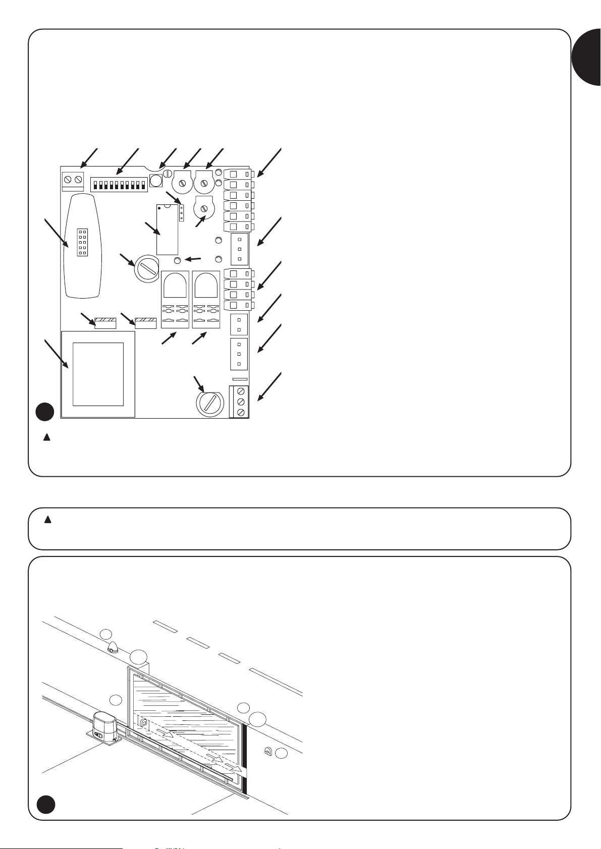
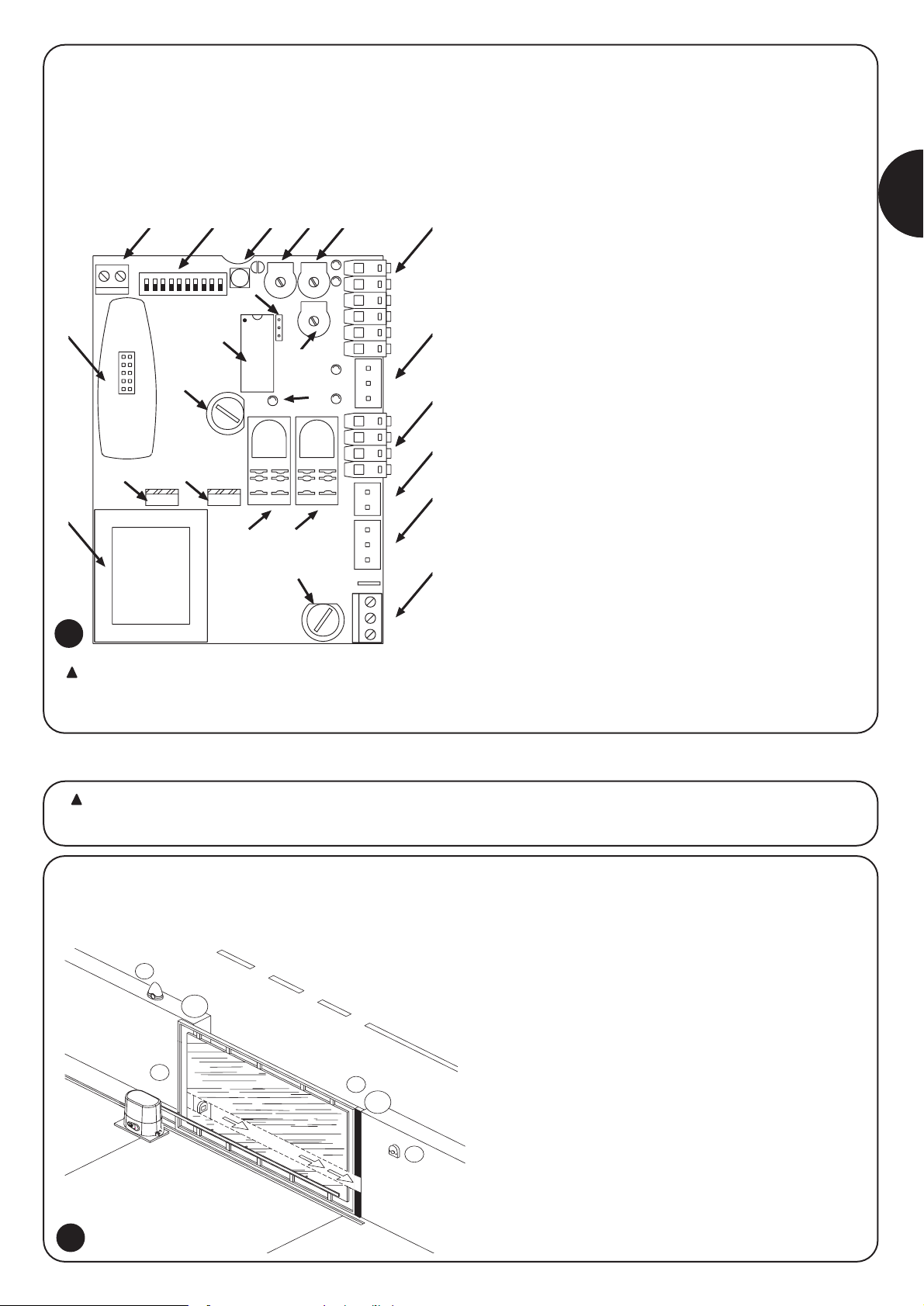
2.2.1) Electrical diagram
POWER LINE
P.P.
PHOTOCELL
FCA
FCC
PHOTOTEST
24 Vac
0 Vac
8
GND
LUX
Max 40W
AERIAL
PHOTO
CELL
P.P.
ALT
11
10
9
12
13
COURTESY
LIGHT
4
5
6
L
3
1
2
7
N
RADIO
2.2) Electrical connections
To safeguard the operator and avoid damaging the
components while you are wiring or plugging in the
various cards: under no circumstances may the unit be
electrically powered.
• Power the unit using a 3 x 1,5mm
2
cable: should the distance
between the unit and the earth connection exceed 30m, install
an earth plate near the unit.
• Use wires with a minimum cross-section of 0.25mm
2
to connect
low voltage safety circuits.
• Use shielded wires if the length exceeds 30m and only connect
the earth braid to the control unit side.
• Do not make connections to cables in buried boxes even if they
are completely watertight.
• If the inputs of the Normally Closed (NC) contacts are not used
they should be jumped with the “24V common” terminal except
for the photocell inputs if the phototest function is enabled, for
further information please see the “Phototest” paragraph.
• If there is more than one (NC) contact on the same input, they
must be connected in SERIES.
• If the inputs of the Normally Open (NA) contacts are not used
they should be left free.
• If there is more than one (NA) contact on the same input, they
must be connected in Parallel.
• The contacts must be mechanical and potential-free; no stage
connections are allowed, such as those defined as "PNP",
"NPN", "Open Collector" etc.
!
2.2.2) Description of connections
A brief description of the possible control unit output connections follows.
Terminals Functions Description
1-2-3 : Power input = Mains power Line
4 - 5 : Flashing light = Output for connecting flashing light to mains voltage (Max. 40W)
6 – 7 : Courtesy light = Clean contact output for courtesy light connection ( Max. 5A)
8 - 9 : 24 Vac = 24Vac output to 24Vac +/- 25% services (Max. 150mA)
9 : Common = Common for all inputs
10 : Phototest = Phototest output (“TX” power supply to photocells) Max. 50mA
11 : Stop = Input with “Stop” function (Stop and short reverse run)
12 : Photo = Input for safety devices
13 : Step by step (PP) = Input for cyclic functioning (“Open” – “Stop” – “Close” – “Stop”)
: Aerial = Input for the radio receiver aerial
3
Page 7
GB
7
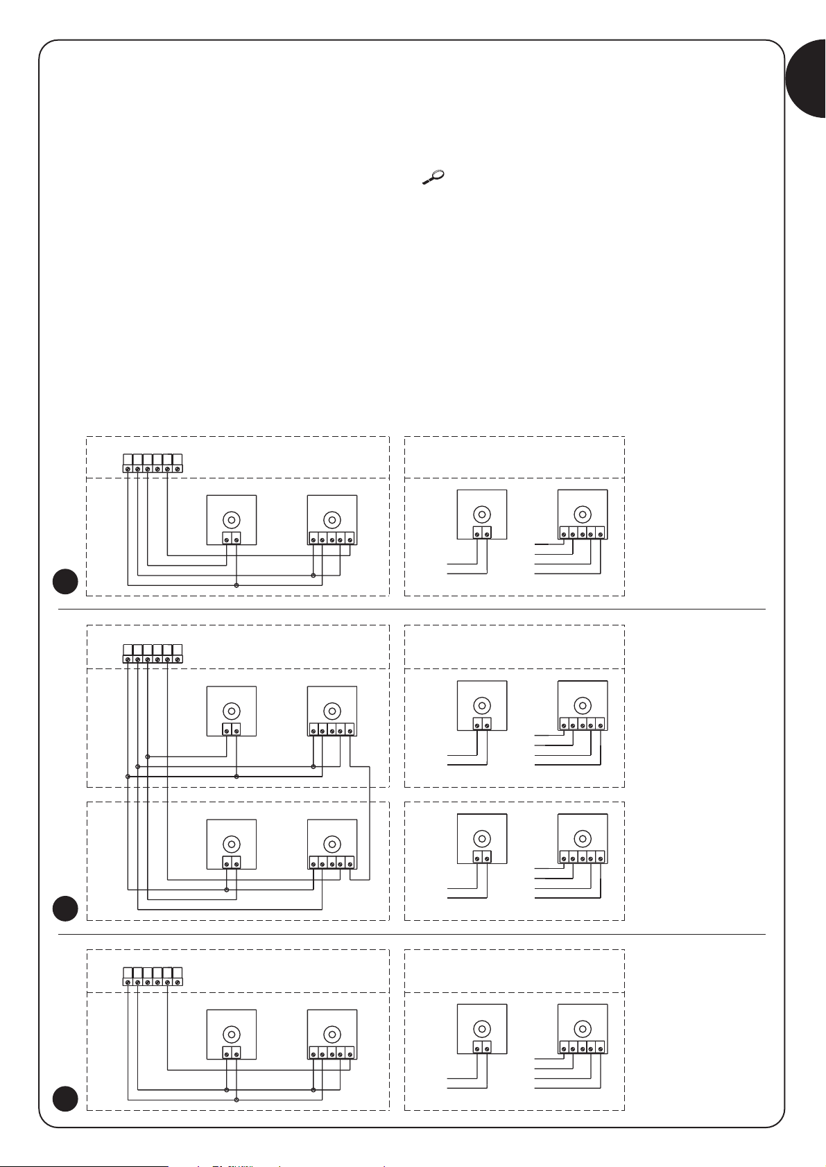
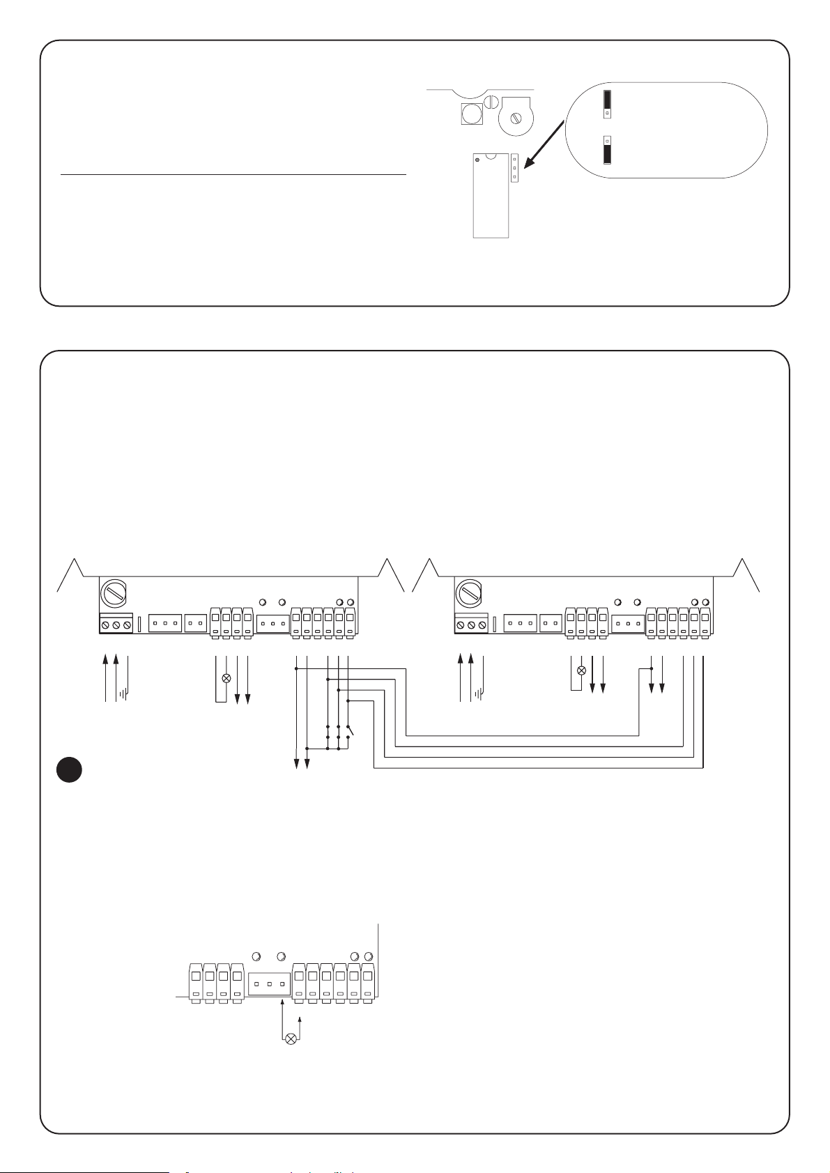
2.2.3) Phototest
Phototest” is the best possible solution for safety devices in terms of
reliability and it puts the control unit and safety photocells in
“category 2” according to UNI EN 954-1 standard (ed. 12/1998).
Before every manoeuvre is begun, the relative safety devices are
checked and only if everything is in order will the manoeuvre start.
Should the test be unsuccessful (the photocell is blinded by the sun,
cables have short circuited, etc.) the failure is identified and the
manoeuvre is not carried out.
To obtain the Phototest function:
• Set Dip-Switch 10 to ON
• Connect the two photocells as shown in fig. 4a (when using a
single pair of photocells) or as shown in fig. 4b (when using two
pairs of photocells), where the power supply for the photocell
transmitters is not taken directly from the service output but from
the “Phototest” output between the terminals (8-10). The
maximum current available at the “Phototest” output is 50mA (2
pairs of Nice TX)
• Power the receivers directly from the service output of the
control unit (terminals 8-9).
When using 2 pairs of photocells which may interfere with each
other, activate the synchronisation function as described in the
photocell instructions.
If at a later time the Phototest function is no longer required, set Dip-
Switch 10 to the OFF position.
The photocells are tested as follows: when movement is required, it
is first checked that all the receivers involved in the movement give
their consent, then power to the transmitters is disconnected after
which it is checked that all the receivers signal the fact by removing
their consent; the transmitters are then powered and the consent of
all the receivers is verified once more. Only if this sequence is
successfully carried out will the manoeuvre be performed.
3 4 5
RX
12
9
9
8
TX
21
9
8
12
RX
4 5
PHOTOCELL
321
TX
PHOTOCELL
21
1311 12
9
8
10
RxA
RxB
5421 3
12
9
8
PHOTOCELL
B
5
RXBTXB
21
8
10
RXB
45321
TXB
PHOTOCELL
B
21
5421 3
9
8
PHOTOCELL
A
5
9
RXATXA
21
8
10
4 5
RXA
1311 12
2 31
TXA
PHOTOCELL
A
1 2
9
8
10
12 131110
9
8
RX
34 512
9
9
12
8
PHOTOCELL
1 2
10
8
RX
34 51 2
TX
12
PHOTOCELL
TX
4a
4b
4c
fig. 4a
Photo with connection
for phototest
fig. 4b
Photo A and photo B with
connection
for phototest
fig. 4c
Photo with connection
without phototest
Page 8
8
2.2.4) Checking connections
The following operations entail working on live circuits; most of
these run on extra-low safety voltage so they are not dangerous but
some are contain mains voltage which means they are HIGHLY
DANGEROUS!
Pay the greatest of attention to what you are doing and NEVER
WORK ALONE!
• Power the unit and check that voltage between terminals 8-9 is
approx. 24Vac.
• Check that the “OK” Led flashes rapidly for a few moments and
then that it flashes at a regular frequency.
• Now check that the Led’s relative to the N.C. (Normally Closed)
contacts are on (all safety devices active) and that the Led’s
relative to the N.A. (Normally Open) inputs are off (no command
present); if this is not the case, check the connections of the
various devices and make sure they are in good working order.
The STOP input switches off both FCA and FCC.
• Make sure the limit switches are connected properly; move the
limit switch lever and check that the relative limit switch cuts in
and switches off the relative Led on the control unit.
• Release the leaf, take it to the halfway point and then block it; it
is now free to move in either the opening or closing direction.
• Now make sure that movement occurs in the right direction, that
is, see whether the movement set on the unit corresponds to
that of the leafs. This check is of paramount importance, if the
direction is wrong, in some cases (in the “Semiautomatic” mode,
for instance) the “Automatic” system might appear to be working
properly; in fact, the “Open” cycle is similar to the “Close” cycle
but with one basic difference: the safety devices are ignored in
the closing manoeuvre which is normally the most dangerous,
and they will trigger in the opening manoeuvre causing the gate
to close against the obstacle with disastrous results!
• To see whether or not the direction of rotation is correct, give a
short pulse to the Step-by-Step (PP) input; the first manoeuvre
the unit will carry out after being powered is always an “Open”
one, so simply verify that the automatic system moves in the
opening direction; if this movement is incorrect, proceed as
follows:
Turn the power off
Turn the motor and the limit switch power connectors
180°. (Ref. “L” and Ref. “G” of fig.1)
Once this has been done, check whether the direction of
rotation is now correct by repeating previous point.
The “OK” Led located in the centre of the board has the task of
signalling the status of the internal logic: regular flashing at 1 second intervals
indicates that the internal microprocessor is active and waiting for commands.
When the microprocessor recognises a variation in the state of an input
(whether it is a command or a function Dip-Switch input) it generates a rapid
double flash even if the variation does not have any immediate effect.
Extremely rapid flashing for 3 s means that the control unit has just been
powered or is carrying out internal testing. Irregular flashing, lastly, means that
the test has been unsuccessful and that a fault has occurred.
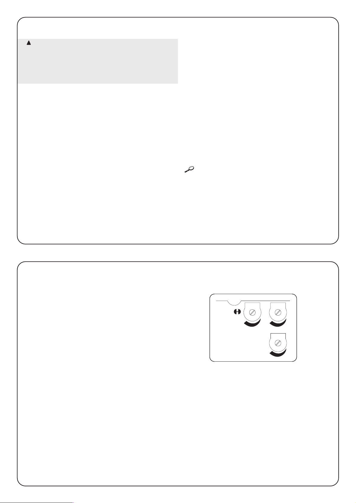
Adjustments can be made with the trimmers that modify the
following parameters:
Working time (TL):
Adjusts the maximum duration of the opening or closing manoeuvre.
To adjust the working time TL, select the “Semiautomatic” operating
mode by moving Dip-Switch 1 to ON and adjust the TL trimmer to
halfway along the travel distance. Then run a complete opening
cycle followed by a complete closing cycle and readjust the TL
trimmer in order to leave enough time for the whole manoeuvre plus
a margin of about 2 to 3 s.
If the trimmer is at maximum and there still is not enough time, cut
the TLM jumper on the printed circuit near the TL trimmer, in order
to provide more working time.
If you wish to use the deceleration function, adjust the Trimmer so
that the deceleration stage starts 50 - 70cm before the limit switch
is triggered.
The modification of the working time will be effective starting with the
next opening manoeuvre.
Pause Time (TP):
In the “Automatic” mode, this adjusts the delay between the end of
the opening manoeuvre and the beginning of the closing manoeuvre.
To adjust Pause Time TP, select the “Automatic” operating mode by
moving Dip-Switch 2 to ON and adjust the TP trimmer as required.
Then carry out an opening manoeuvre and check the time elapsed
before “Automatic” closing manoeuvre.
Force (F):
Take great care when adjusting the Force (F) trimmer as this may
affect the level of safety of the automatic system. Trial by error is
required to adjust this parameter, measuring the force applied to the
leaf and comparing it with regulatory values.
3) Adjustments:
F
TL TP
TLM
!
Page 9

GB
9
After the above checks and adjustments, the system can now be tested.
The automation system must be tested by qualified and expert personnel who must establish what tests to perform
according to the relative risk.
Testing is the most important part of the whole installation phase. Each single component, e.g. the gearmotor, emergency stop, photocells,
etc., may require a specific test phase; please follow the procedures shown in the respective instructions manuals.
To test the control unit, perform the following operations:
1. Function selection:
• Set Dip-Switch 1 to ON (“Semiautomatic” operation)
• Set all the other Dip-Switches to OFF
2. Press the “Step-by-Step” button and check that:
• An opening manoeuvre starts
• The flashing lamp activates
• The movement stops when the opening limit switch FCA is reached.
3. Press the “Step-by-Step” button again and check that:
• A closing manoeuvre starts
• The flashing lamp activates
• The movement stops when the closing limit switch FCC is reached CC
4. Start an opening manoeuvre and check that during the manoeuvre the triggering of a device:
• Connected to the “Stop” input causes an immediate stop and a short reverse run
• Connected to the “Photo” input stops and reverses the manoeuvre
5. Start a closing manoeuvre and check that during the manoeuvre the cut-in of a device:
• Connected to the “Stop” input causes an immediate stop and a short reverse run
• Connected to the “Photo” input stops and reverses the manoeuvre
6. Press the “Step-by-Step” button and make sure that each activation of the input generates a step in the following sequence:
• “Open” – “Stop” – “Close” – “Stop”
7. If the “Phototest” function is used, check the test is efficient:
• Interrupt the “Photo” photocell, then start a manoeuvre and check this is not performed
• Short the “Photo” photocell contact, then start a manoeuvre and check this is not performed.
8. Perform the tests for detecting Impact Forces as required by EN 12445.
If further functions are activated after testing has finished that could reduce the safety of the system, specific testing of these functions must
be performed.
!
4) Testing
Page 10
10
5) Operating modes
In the manual operating mode, the “Step-by-Step” input enables an
alternating closing and opening manoeuvre.
Movement stops as soon as the input command stops. During an
opening or closing manoeuvre, movement will stop also when the limit
switches are triggered; moreover, during a closing manoeuvre,
movement will stop also if the “Photocell” enable signal fails. During both
opening and closing manoeuvres, the activation of the “ALT” command
will always cause an immediate stopping of movement and a short
reverse run. When a movement is stopped, stop the input command
before giving a command to start a new movement.
When one of the automatic functioning modes (“Semiautomatic”,
“Automatic” o “Close Always”) is operational, a command impulse to
the “Step by step” input begins an alternating closing and opening
manoeuvre. A second impulse to the “Step by step” will cause it to stop.
Both in the opening and closing phases, the activation of the “ALT”
command will cause an immediate stopping of movement and a
short reverse run.
If an automatic functioning mode has been chosen, the opening
manoeuvre will be followed by a pause and then a closing
manoeuvre. If “Photocell” triggers during the pause, the timer will be
reset with a new pause time; if, on the other hand, there is a “Stop”
during the pause, the closing function will be cancelled and the
system will “Stop”.
Nothing will happen if “Photocell” triggers during an opening
manoeuvre; if “Photocell” triggers during a closing manoeuvre, this
will invert the direction of movement followed by a pause and then a
closing manoeuvre.
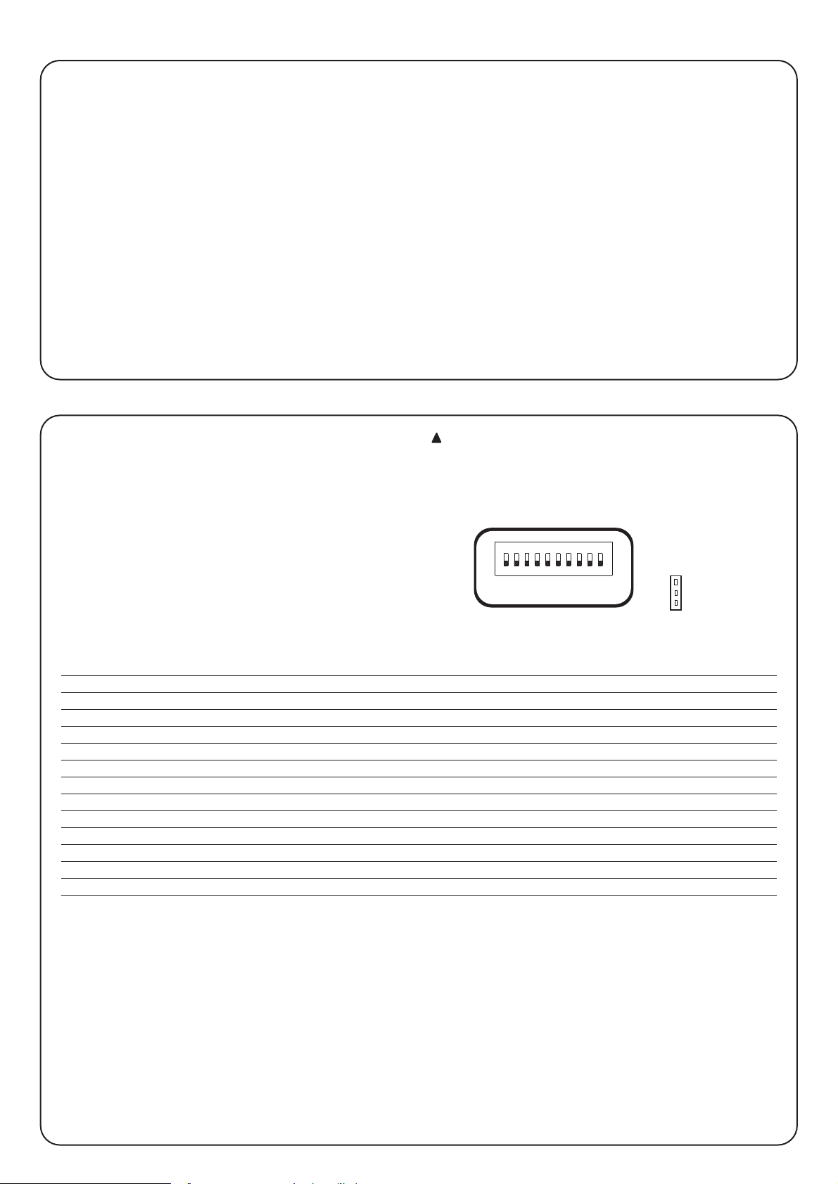
The unit features a set of microswitches used to operate various
functions so as to make the system more suitable to user needs and
safer in various conditions of use. All the functions can be activated by
moving the relative Dip-Switch to the “On” position and deactivated by
moving them to “Off”.
Some of the programmable functions are linked to
safety aspects; carefully evaluate the effects of a function
and see which gives the highest possible level of safety.
!
Use the Dip-Switches to select the various operating modes and add the functions required according to this table:
Switch 1-2: Off-Off = “Manual” movement (i.e.: man Present)
On -Off = “Semiautomatic” movement
Off-On = Automatic” movement (i.e.: automatic closing
On -On = “Automatic + always “Closes” movement
Switch 3: On = Condominium operating mode <not available in the manual mode>
Switch 4: On = Pre-flashing
Switch 5: On =
Close 5” after “Photo” < in “Automatic” > or “Close” after Photo <in “Semiautomatic” >
Switch 6: On = “Photo” safety also in opening
Switch 7: On = Gradual departure
Switch 8: On = Deceleration
Switch 9: On = Brake
Switch 10: On = Phototest
Selector switch JP1: = Courtesy light in impulse mode
6) Programmable functions
101
JP1
Page 11

GB
11
6.1) Description of functions
Here is a brief description of the functions that can be added by moving the relative Dip-Switch to “ON”.
Switch 1-2: Off-Off = “Manual” movement (man present)
On-Off = “Semiautomatic” movement
Off-On = “Automatic” movement (automatic closing)
On-On = “Automatic + Always Closes” movement
In the “Manual” operating mode, the gate will only move as long as the relative control button is held down.
In the “Semiautomatic” operating mode a command impulse will perform the whole movement until the Working Time limit expires or the
mechanical stop is reached. In the “Automatic” operating mode, an opening manoeuvre is followed by a pause and then an automatic closing
manoeuvre.
The “Always Closes” function comes into play following a power failure; if the gate is open, a closing manoeuvre takes place, automatically
preceded by 5 seconds of pre-flashing.
Switch 3: On = Condominium operating mode (not available in the Manual mode)
In the Condominium operating mode, once an opening manoeuvre has started it cannot be interrupted by other command pulses on “Stepby-Step” until the gate has finished opening.
During a closing manoeuvre, a new command pulse will stop the gate and reverse the direction of movement in order to open the gate.
Switch 4: On = Pre-flashing
A command impulse activates the flashing lamp followed by movement 5 s later (2 s later in the manual mode).
Switch 5: On =
“Close” 5 s. after Photo <in the “Automatic” mode > or “Close” after Photo <in the “Semiautomatic” mode >
This function, if in the “Automatic” mode, allows the gate to be kept open only for the time required for transit; when “Photo” finishes, the
manoeuvre stops. After 5 s a closing manoeuvre will automatically begin. If “Photo” triggers in the “Semiautomatic” mode during a closing
manoeuvre the “Automatic” closing manoeuvre is activated with the adjusted pause time.
Switch 6: On = Safety “Photo” also during the opening manoeuvre
The “Photo” safety device is normally just active during the closing manoeuvre; if Dip-Switch 6 is turned "On" the safety device will also trigger
during the opening manoeuvre.
In the “Semiautomatic” or “Automatic” modes, the opening manoeuvre will start again immediately after the photocell has been disengaged.
Switch 7: On = Gradual departure
Starts the manoeuvre gradually, preventing the automatic system from being jolted.
Switch 8: On = Deceleration
Deceleration reduces speed to 30% of rated speed in order to limit the force of the impact in the gate’s opening and closing areas.
Once the deceleration function has been activated, it will be necessary to adjust the Working Time Trimmer (TL), since the starting of
deceleration is connected with the established working time. Therefore, adjust the working time to ensure that deceleration starts
approximately 50-70 cm before the triggering of the limit switch.
As well as reducing the speed of the manoeuvre, the deceleration function also reduces motor torque by 70%.
For systems requiring elevated torque, this decrease may cause the motor to stop immediately.
Switch 9: On = Brake
At the end of the movement a motor brake procedure is performed, initially slight and then more incisive in order to stop the gate rapidly but
without jolts.
Switch 10: On = Phototest
This function controls photocell efficiency at the beginning of each manoeuvre. See the “Phototest” chapter.
Page 12
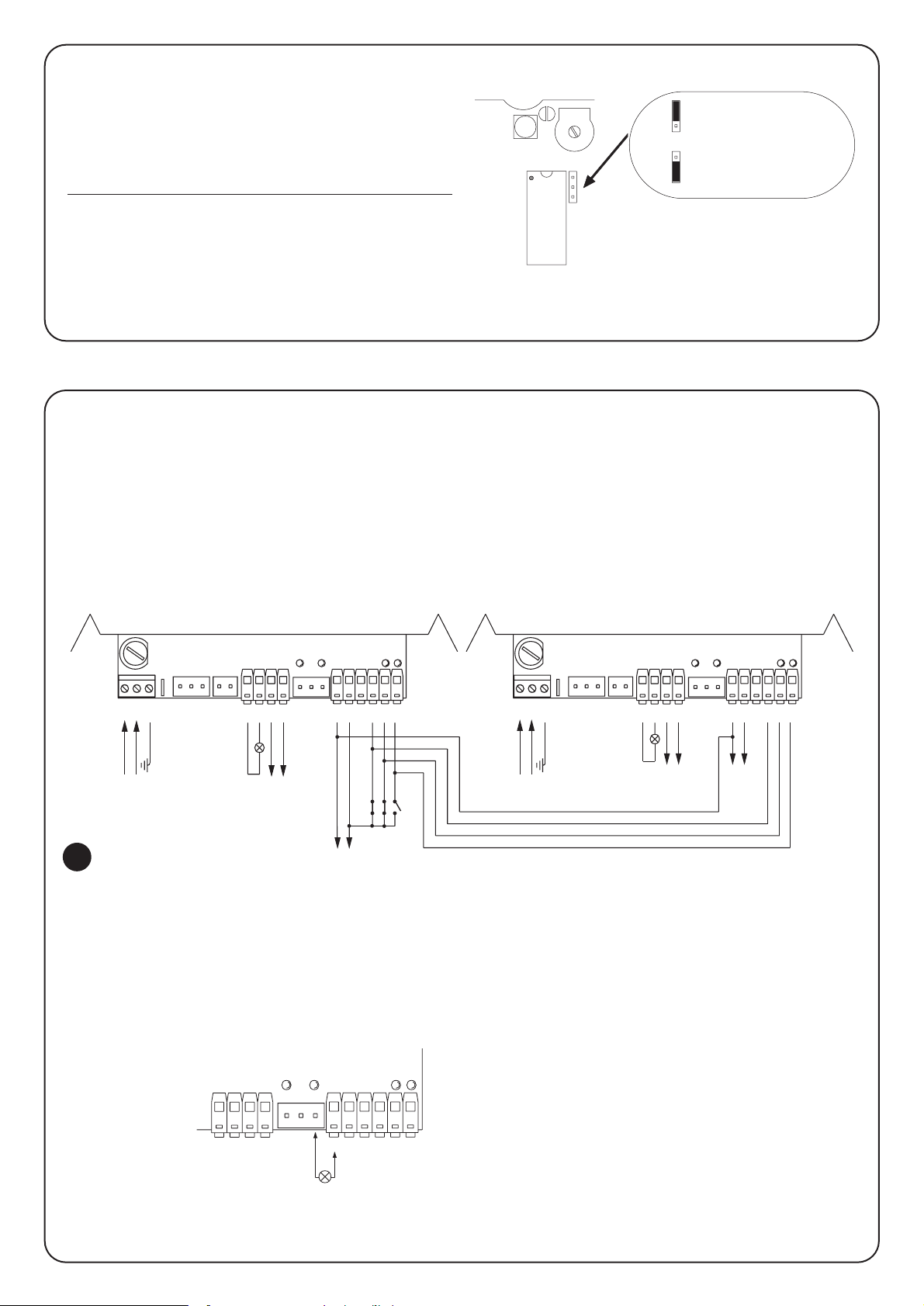
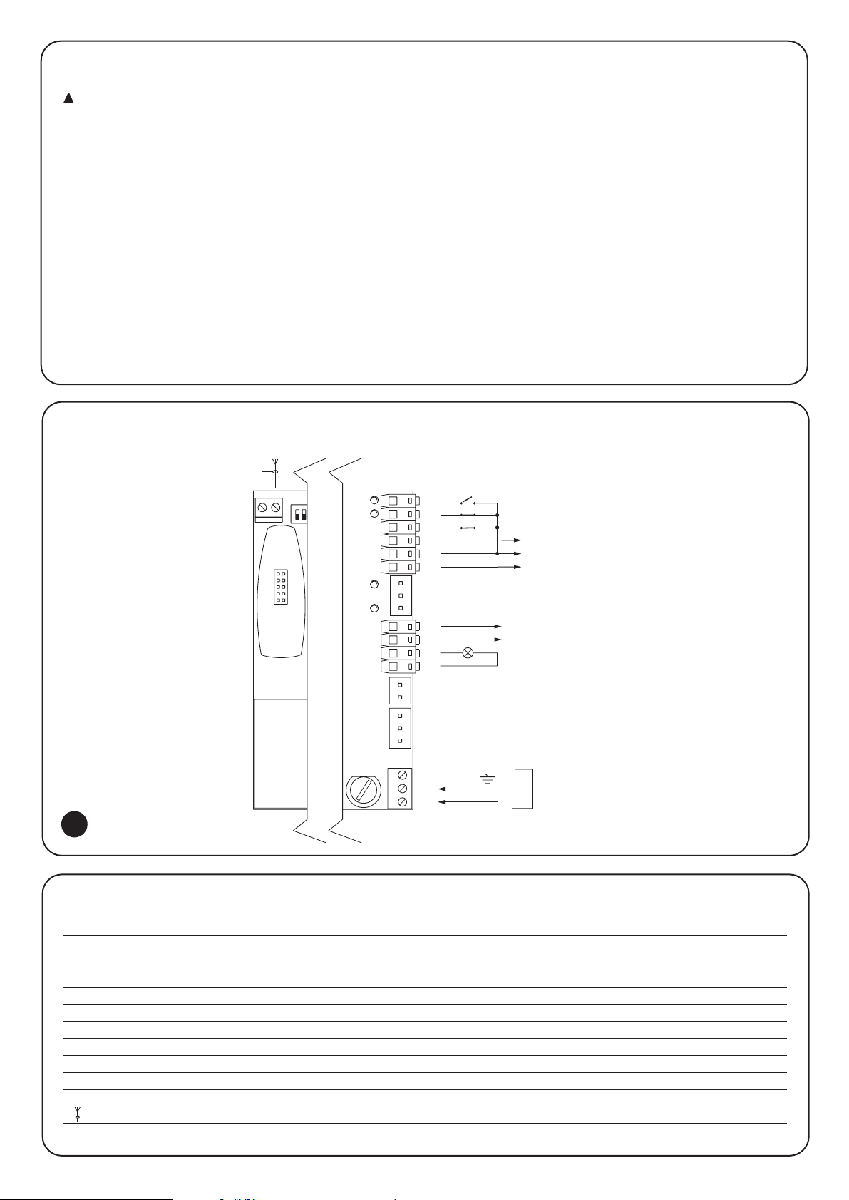
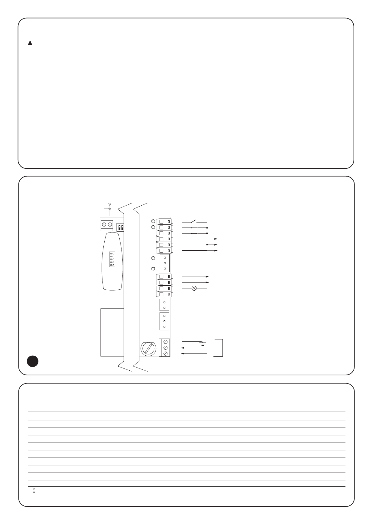
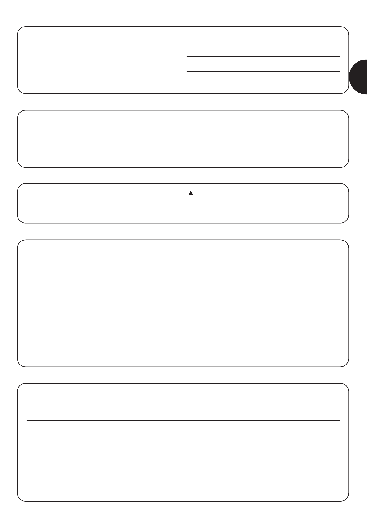
Connect two control units on opposing leaves:
To create an automation system working with 2 opposing leaves:
• Use two motors with the control units connected as indicated in
fig.5.
• Connect the flashing light end the “Gate Open Indicator” to any
one of the two control units..
• The inputs must be connected in parallel.
• The “Common” of the inputs can be connected to one of the 2
control units.
• Connect the 0Volts (Terminal 8) of the two control units.i.
• The “Phototest” function must not be used.
• The “Condominium” function (Dip-Switch 3) should be fitted as
this allows the leaves to be resynchronised if the 2 control units
become unsynchronised.
7) How to...
N
7
213
L
654
COURTESY
LIGHT
13
12
91011
STOP
P. P.
FOTO
Max 40W
LUX
GND
8
0 Vac
24 Vac
FCC
FCA
PHOTOCELL
STEP BY STEP
11
0 Vac
24 Vac
LIGHT
Max 40W
GND
3
N
L
1
2
LUX
COURTESY
547
6
8910
FCA
FCC
12
13
PHOTO
CELL
P. P.
5
Courtesy light in impulse mode:
In this mode, the clean contact of the courtesy light output will
remain closed for 1 sec. at the starting of each opening or closing
manoeuvre, thus enabling a command impulse to be sent to an
external timer.
Courtesy light in standard mode:
In this mode, the clean contact of the courtesy light output will
remain closed for as long as required by the opening or closing
manoeuvre, plus an additional 60 seconds.
Courtesy light in
impulse mode
Courtesy light in
standard mode
FCC
FCA
STEP BY STEP
546
11
9
8
10
12
13
24 Vac
WARNING LIGHT
Max 1W
PHOTOCELL
Connect a “gate open” warning light:
12
Page 13
“RADIO” Card
The control unit features a connector for plugging in a radio card
SMXI, which activates the “Step-by-Step” and “Stop” input and
allows the control unit to be remote-controlled with a transmitter.
output 1 Step by Step
output 2 STOP
output 3 not used
output 4 not used
8) Accessories
The control unit, being electronic, needs no particular maintenance.
However, periodically make sure (at least once every six months) that
the device adjusting motor force is in perfect working order; adjust
with the trimmer if necessary.
Carry out the whole test phase again to check that the limit switches,
safety devices (photocells, pneumatic edges, etc.) and the flashing
light are in perfect working order.
9) Maintenance
This product is made from various kinds of material, some of which
can be recycled.
Make sure you recycle or dispose of the product in compliance with
current laws and bye-laws.
Some electric components may contain polluting
substances; do not dump them.
!
10) Disposal
This section will help fitters to solve some of the most common
problems that may arise during installation.
No LED is on
• Check whether the control unit is powered (check mains voltage
is present at terminals 1-2 and a voltage of approx. 24 Vac at
terminals 8-9)
•
Check the 2 mains fuses have not blown; if none of the Led’s is
on a serious fault has probably occurred and the control unit
should therefore be replaced.
The OK LED flashes regularly but the INPUT Led’s do not
reflect the state of the respective inputs
• Carefully check the connections on input terminals 8÷13.
The manoeuvre does not start
• Check that the Led’s of the “Stop” (FCA + FCC) and “Photo”
safety device are on and that the relative command Led that is
activated (“Step-by-Step”) remains on for the whole duration of
the command.
The gate changes direction during a manoeuvre
An inversion is caused by:
• The photocell triggering (“Photo” during the closing manoeuvre);
in this case, check the connections of the photocells and check
the input Led’s.
11) What to do if ….
Mains power input : 230 Vac 50/60 Hz
Versions /V1 : 120 Vac 50/60 Hz
Max. current for 24V services : 200mA (the voltage may vary ± 25%)
Flashing lamp output : For flashing lamps at mains voltage, maximum power 40 W
Courtesy light output : Clean contact max. 5A
Operating temperature : -20 ÷ 70 °C
Working Time : Adjustable from 2.5 to > 40 s., or from < 40 to > 80 s. with TLM
Pause Time : Adjustable from 5 to > 80 s
12) Technical specifications
GB
13
Page 14
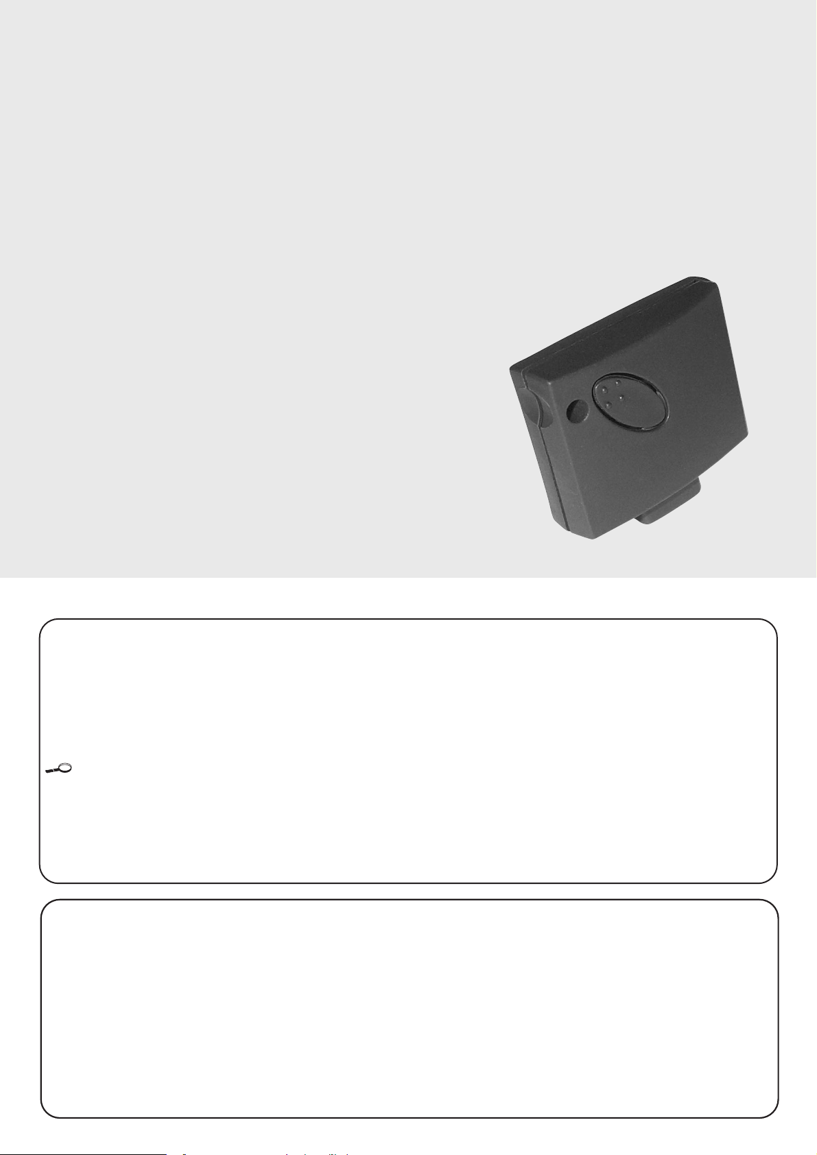
smxi radio receiver
Description of the product
The special thing about this type of radio receiver is that the
recognition code is different for each transmitter (it also changes
every time it is used).
Therefore, in order to allow the receiver to recognise a determined
transmitter, the recognition code must be memorised. This operation
must repeated for each transmitter required to communicate with the
control unit.
Up to a maximum of 256 transmitters can be memorised in the receiver.
No one transmitter can be cancelled; all the codes must be deleted.
During the transmitter code memorisation phase, one of these
options may be chosen:
Mode I. Each transmitter button activates the corresponding output
in the receiver, that is, button 1 activates output 1, button 2 activates
output 2, and so on. In this case there is a single memorisation phase
for each transmitter; during this phase, it doesn’t matter which button
is pressed and just one memory sector is occupied.
Mode II. Each transmitter button can be associated with a particular
output in the receiver, e.g., button 1 activates output 2, button 2
activates output 1, and so on. In this case, the transmitter must be
memorised, pressing the required button, for each output to activate.
Naturally, each button can activate just one output while the same
output can be activated by more than one button. One memory
section is occupied for each button.
Installing the aerial
The receiver requires an ABF or ABFKIT type aerial to work properly;
without an aerial the range is limited to just a few metres. The aerial
must be installed as high as possible; if there are metal or reinforced
concrete structures nearby you can install the aerial on top. If the
cable supplied with the aerial is too short, use a coaxial cable with 50Ohm impedance (e.g. low dispersion RG58), the cable must be no
longer than 10 m.
If the aerial is installed in a place that is not connected to earth
(masonry structures), the braid’s terminal can be earthed to provide a
larger range of action. The earth point must, of course, be local and
of good quality. If an ABF or ABFKIT aerial cannot be installed, you
can get quite good results using the length of wire supplied with the
receiver as the aerial, laying it flat.
14
Page 15
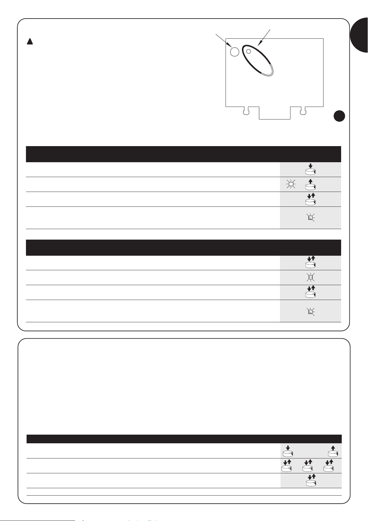
Memorising a remote control
When the memorisation phase is activated, any
transmitter correctly recognised within the reception
range of the radio is memorised. Consider this aspect with
care and remove the aerial if necessary to reduce the
capacity of the receiver.
The procedures for memorising the remote controls must be
performed within a certain time limit; please read and understand the
whole procedure before starting.
In order to carry out the following procedure, it is necessary to use the
button located on the box of the radio receiver (reference A, Fig. 1b),
and the corresponding LED (reference B, Fig. 1b) to the left of the
button.
!
3s
2s
x3
2s
x3
1. Press and hold down the receiver button for at least 3 seconds
2. Release the button when the Led lights up
3.
Within 10 seconds press the 1st button on the transmitter to be memorised,
holding it down for at least 2 seconds
N.B.: If the procedure was memorised correctly, the Led on the receiver will flash 3 times.
If there are other transmitters to memorise, repeat step 3 within another 10 seconds
The memorisation phase finishes if no new codes are received for 10 seconds.
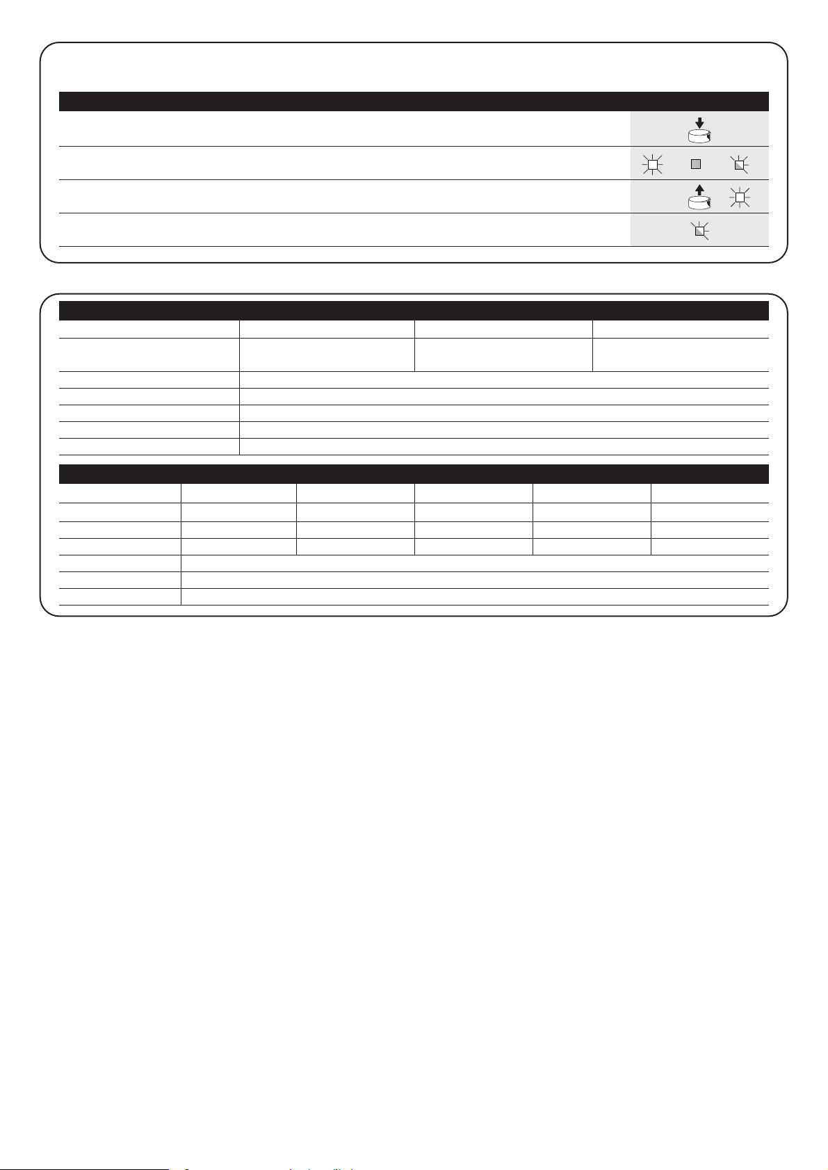
Table “B1” Mode I memorising Example
(each button activates the corresponding output in the receiver)
1. Press and release the receiver button as many times as the number of the
desired output (twice for output no. 2)
2.
Make sure the Led flashes as many times as the number of the desired
output (2 flashes for output no. 2).
3.
Within 10 seconds press the desired button on the transmitter to be memorised,
holding it down for at least 2 seconds.
N.B.: If the procedure was memorised correctly, the Led on the receiver will flash 3 times.
If there are other transmitters to memorise, repeat step 3 within another 10 seconds
The memorisation phase finishes if no new codes are received for 10 seconds.
Table “B2” Mode II memorising Example
(each button can be associated with a particular output)
RX
RX
TX
TX
RX
1b
x5s
1s 1s 1s
x1
1. Press the button on the NEW transmitter for at least 5 seconds and then release
2. Press the button on the OLD transmitter 3 times slowly
3. Press the button on the NEW transmitter slowly and then release
N.B.: If there are other transmitters to memorise, repeat the above steps for each new transmitter
Table “B3” Remote Memorising Example
TX
TXTXTX
TX
TX
Remote memorising
It is possible to enter a new transmitter in the receiver memory
without using the keypad. A previously memorised and operational
remote control must be available. The new transmitter will “inherit”
the characteristics of the previously memorised one. Therefore, if the
first transmitter is memorised in mode I, the new one will also be
memorised in mode I and any of the buttons of the transmitter can
be pressed. If the first transmitter is memorised in mode II the new
one will also be memorised in mode II but the button activating the
required output must be pressed on the first transmitter as must the
button required to be memorised on the second. You need to read all
the instructions in advance so you can perform the operations in
sequence without interruptions. Now, with the two remote controls
(the NEW one requiring code memorisation and the OLD one that is
already memorised), position yourself within the operating range of
the radio controls (within maximum range) and carry out the
instructions listed in the table.
GB
15
B
A
Page 16
16
FLOR VERY VR FLO VERY VE SMILO
Buttons 1 – 2 - 4 2 1 – 2 - 4 2 2 - 4
Power input 12Vdc Batt. 23A 6Vdc lithium batt. 12Vdc Batt. 23° 6Vdc lithium batt. 12Vdc Batt. 23A
Absorption 10mA 10mA 15mA 10mA 25mA
Frequency 433.92MHz
Working temp. -40°C ÷ + 85°C
Radiated power 100µW
Deleting all transmitters
All the memorised codes can be deleted as follows:
x3
3°
x5
1. Press the receiver button and hold it down
2. Wait for the Led to light up, then wait for it to switch off
and then wait for it to flash 3 times
3. Release the button exactly during the third flash
N.B.: if the procedure was performed correctly, the Led will flash 5 times after a few moments.
Receivers
Transmitters
Table “B4” Deleting all transmitters Example
RX
RX
SMXI SMXIS SMXIF
Decoding Rolling code Rolling code 1024 FLO combinations
52 bit FLOR 64 bit SMILO
Frequency 433.92MHz
Input impedance 52ohm
Outputs 4 (on connector SMXI)
Sensitivity better than 0.5µV
Working temp. -10°C ÷ + 55°CC
Technical characteristics
Page 17

Dichiarazione CE di conformità / EC declaration of conformity
(secondo Direttiva 98/37/EC, Allegato II, parte B) (according to 98/37/EC Directive, Enclosure II, part B)
Numero /Number : 151/SMXI Data / Date: 5/2002 Revisione / Revision: 0
Il sottoscritto Lauro Buoro, Amministratore Delegato, dichiara che il prodotto:
The undersigned Lauro Buoro, General Manager, declares that the product:
Nome produttore / Producer name:
NICE s.p.a.
Indirizzo / Address: Via Pezza Alta 13, 31046 Z.I. Rustignè –ODERZO- ITALY
Tipo / Type: Ricevitore radio 433MHz / Radio receiver 433MHz
Modello / Model: SMXI, SMXIS, SMXIF
Risulta conforme a quanto previsto dalle seguenti Norme armonizzate / Complies with the following Harmonised standards
Riferimento n° Edizione Titolo
Livello di valutazione
Classe
Reference n° Issue Title Assessment level Class
1999/5/CE 1999 DIRETTIVA R&TTE/R&TTE Directive
ETS300683 1997 Radio Equipment and Systems (RES);Electromagnetic Compatibility (EMC) II
standard for Short Range Devices (SRD) operating on frequencies between 9KHz and 25GHz
EN300220-3 2000 APPARATI RADIO E SISTEMI - CARATTERISTICHE TECNICHE E METODI DI MISURA I (LPD)
PER APPARATI RADIO TRA 25MHz A 1000MHz
Radio Equipment and Sistems- Short Range Devices-Technical characteristics and test
methods for radio equipment between 25MHz and 1000MHz
REGOLAZIONE ALL’USO DEI DISPOSITIVI A CORTO RAGGIO
Regolating to the use of short range devices (SRD)
EN60950 2nd ed. 1992 APPARECCHIATURE PERLA TECNOLOGIA DELL’INFORMAZIONE. SICUREZZA.
+A1: 1993 + A2: 1993 + A3: 1995 + A4: 1997 + A11: 1997 + EN41003/1993.
Inoltre dichiara che non è consentita la messa in servizio del prodotto suindicato finché la macchina, in cui il prodotto stesso è incorporato,
non sia identificata e dichiarata conforme alla direttiva 98/37/CEE/ He declares, moreover, that it is not allowed to use the above mentioned product until
the machine, in which this product is incorporated, has been identified and declared in conformity with the regulation 98/37/CEE.
Il prodotto suindicato si intende parte integrante di una delle configurazioni di installazione tipiche, come riportato nei nostri cataloghi generali
The above mentioned product is meant integral part of the of one of the installation configuration as shown on our general catalogues
Oderzo, li 13 Maggio 2002 (Amministratore Delegato)
(General Manager)
Lauro Buoro
17
GB
Page 18
18
centrale comando
motoriduttori
robo, thor
Avvertenze:
Il presente manuale è destinato solamente al personale
tecnico qualificato per l'installazione. Nessuna informazione
contenuta nel presente fascicolo può essere considerata
d’interesse per l'utilizzatore finale!
La centrale è destinata al comando di attuatori elettromeccanici per l’automazione di cancelli, ogni altro uso è
improprio e quindi vietato dalle normative vigenti.
Si consiglia di leggere attentamente tutte le istruzioni, almeno una volta,
prima di procedere con l’installazione.
!
Indice: pag.
1 Descrizione del prodotto 19
2 Installazione 19
2.1 Impianto tipico 19
2.2 Collegamenti elettrici 20
2.2.1 Schema elettrico 20
2.2.2 Descrizione dei collegamenti 20
2.2.3 Fototest 21
2.2.4 Verifica dei collegamenti 22
3 Regolazioni 22
4 Collaudo 23
5 Modi di funzionamento 24
pag.
6 Funzioni programmabili 24
6.1 Descrizione delle funzioni 25
7 Come fare per... 26
8 Accessori Opzionali 27
9 Manutenzione 27
10 Smaltimento 27
11 Cosa fare se… 27
12 Caratteristiche tecniche 27
Page 19
I19I
1) Descrizione del prodotto:
Questa centrale per l’automazione di cancelli e porte automatiche,
permette di comandare motoriduttori in corrente alternata monofase.
Nella centrale sono presenti una serie di funzioni selezionabili tramite
dei Dip-Switch (mini selettori) e delle regolazioni effettuabili tramite
dei Trimmer.
Dei Led posti vicino agli ingressi ne segnalano lo stato; un ulteriore
Led presente vicino al microprocessore, segnala il corretto
funzionamento della logica interna.
Per facilitare il riconoscimento delle parti, in fig.1 sono indicati i
componenti più significativi.
OK
BAC
R
D E
F
G
H
I
L
M
P
S
Z
O
T
U V
Q
N
W
X
Morsettiera per antenna
Dip-Switch di selezione funzioni
Pulsante di Passo Passo
Trimmer di regolazione Tempo Lavoro (TL)
Trimmer di regolazione Tempo Pausa (TP)
Morsettiera Ingressi / Uscite di comando
Connettore ingresso dei finecorsa
Morsettiera uscita lampeggiante / Luce di Cor.
Connettore Condensatore
Connettore uscita alimentazione motore
Morsettiera di alimentazione
Selettore modalità luce di cortesia
Innesto Radio
Microprocessore
Fusibile di bassa tensione (315mA T)
Trimmer di regolazione della forza (F)
Led OK
Trasformatore
Triac “Apre”
Triac “Chiude”
Relè “Comune”
Relè “Luce di Cortesia”
Fusibile di linea (5A T)
A
B
C
D
E
F
G
H
I
L
M
N
O
P
Q
R
S
T
U
V
W
X
Z
1
2.1) Impianto tipico
Per chiarire alcuni termini ed alcuni aspetti di un impianto di automazione per porte o cancelli, riportiamo un esempio tipico.
Ricordiamo che gli impianti di cancelli e porte automatiche
devono essere installati solo da personale tecnico qualificato e
nel pieno rispetto delle norme di legge. Seguire attentamente
le indicazioni del fascicolo : “Avvertenze per l’installatore”.
!
2) Installazione:
2
4
3
FOTO
2
1
1) Coppia di fotocellule
2) Lampeggiante
3) Selettore a chiave
4) Bordo sensibile
In particolare ricordiamo che:
• Tutte le fotocellule prodotte da Nice dispongono del sistema di
sincronismo che permette di eliminare il problema
dell’interferenza tra due coppie di fotocellule (per altri particolari
vedere le istruzioni delle fotocellule)
• La coppia di fotocellule “Foto” in apertura non ha effetto mentre
provoca una inversione durante la chiusura.
• L’intervento del bordo sensibile collegato all’ingresso “ALT”
provoca l’arresto immediato e una breve inversione.
Se dovesse rendersi necessario sostituire un fusibile, rispettare rigorosamente il tipo e le caratteristiche:
Dimensioni (5x20), corrente nominale (es. 5A), caratteristica di fusione (T=ritardata, F=rapida), tensione massima
e potere di interruzione.
!
Page 20
20
2.2.1) Schema elettrico
DA RETE
ALIMENTAZIONE
P.P.
FOTO
FCA
FCC
FOTOTEST
24 Vac
0 Vac
8
GND
LUX
Max 40W
ANT.
FOTO
P.P.
ALT
11
10
9
12
13
CORTESIA
LUCE DI
4
5
6
L
3
1
2
7
N
RADIO
2.2) Collegamenti elettrici
Per garantire l'incolumità dell'operatore e per prevenire danni ai componenti, mentre si effettuano i collegamenti o si innestano le varie schede la centrale deve essere assolutamente spenta.
• Alimentare la centrale attraverso un cavo da 3 x 1,5mm
2
. Se la
distanza fra la centrale e la connessione all'impianto di terra
supera i 30m è necessario prevedere un dispersore di terra in
prossimità della centrale.
• Nei collegamenti della parte a bassissima tensione di sicurezza
usare cavetti di sezione minima pari a 0,25mm
2
.
• Usare cavetti schermati se la lunghezza supera i 30m collegando la calza a terra solo dal lato della centrale.
• Evitare di fare connessioni ai cavi in casse interrate anche se
completamente stagne.
• Gli ingressi dei contatti di tipo Normalmente Chiuso (NC), se non
usati, vanno ponticellati con “comune 24V” esclusi gli ingressi
delle fotocellule nel caso sia inserita la funzione di “Fototest”. Per
ulteriori chiarimenti vedere paragrafo “Fototest”.
• Se per lo stesso ingresso ci sono più contatti (NC) vanno posti in
serie tra di loro.
• Gli ingressi dei contatti di tipo Normalmente Aperto (NA) se non
usati vanno lasciati liberi.
• Se per lo stesso ingresso ci sono più contatti (NA) vanno posti in
parallelo tra di loro.
• I contatti devono essere assolutamente di tipo meccanico e svincolati da qualsiasi potenziale, non sono ammessi collegamenti a
stadi tipo quelli definiti "PNP", "NPN", "Open Collector" ecc.
!
2.2.2) Descrizione dei collegamenti
Riportiamo una breve descrizione dei possibili collegamenti della centrale verso l’esterno.
Morsetti Funzione Descrizione
1-2-3 : Alimentazione = Linea di alimentazione da rete
4 - 5 : Lampeggiante = Uscita per collegamento del lampeggiante a tensione di rete ( Max. 40W)
6 – 7 : Luce di cortesia = Uscita a contatto pulito per collegamento luce di cortesia ( Max. 5A)
8 - 9 : 24 Vac = Alimentazione servizi 24Vac ± 25% ( Max. 150mA)
9 : Comune = Comune per tutti gli ingressi
10 : Fototest = Uscita fototest ( Alimentazione “TX” delle fotocellule ) Max. 50mA
11 : Alt = Ingresso con funzione di “Alt” (Stop e breve inversione)
12 : Foto = Ingresso per dispositivi di sicurezza
13 : Passo-Passo (PP) = Ingresso per movimento ciclico (“Apre” – “Stop” – “Chiude” – “Stop”)
: Antenna = Ingresso per antenna ricevitore radio
3
Page 21
I
21
2.2.3) Fototest
Il “Fototest”, aumenta l’affidabilità dei dispositivi di sicurezza;
permettendo di raggiungere la “categoria 2” secondo la norma
EN 954-1 (ediz. 12/1998) per quanto riguarda l’insieme centrale e
fotocellule di sicurezza.
Ogni volta che viene avviata una manovra vengono controllati i
dispositivi di sicurezza coinvolti; solo se tutto è a posto la manovra
ha inizio. Se invece il test non dà esito positivo (fotocellula accecata
dal sole, cavi in corto circuito, ecc.) viene individuato il guasto e la
manovra non viene eseguita.
Per ottenere la funzione “Fototest” è necessario:
• Impostare il Dip-Switch 10 ON
• Collegare le fotocellule come in fig. 4a (se si utilizza una sola
coppia di fotocellule) o come in fig. 4b (se si utilizzano 2 coppie
di fotocellule) nei quali l’alimentazione dei trasmettitori delle
fotocellule non è presa direttamente dall’uscita dei servizi, ma da
l’uscita “Fototest” tra i morsetto (8-10). La corrente massima
utilizzabile sull’uscita “Fototest” è di 50mA (2 coppie di TX Nice)
• Alimentare i ricevitori direttamente dall’uscita servizi della
centrale (morsetti 8-9).
Nel caso in cui si usino 2 coppie di fotocellule che possano interferire
tra loro, attivare il sincronismo come descritto nelle istruzioni delle
fotocellule.
Se in un secondo momento non si desiderasse più utilizzare la funzione
di Fototest, sarà sufficiente porre in posizione OFF il Dip-Switch 10.
Il test delle fotocellule avviene in questo modo: quando è richiesto un
movimento, in primo luogo viene controllato che tutti i ricevitori
interessati dal movimento diano il consenso, poi viene spenta
l’alimentazione ai trasmettitori e quindi verificato che tutti i ricevitori
segnalino il fatto togliendo il loro consenso; infine viene riattivata
l'alimentazione dei trasmettitori e quindi nuovamente verificato il
consenso da parte di tutti i ricevitori. Solo se questa sequenza ha
esito positivo, la manovra verrà avviata.
3 4 5
RX
12
9
9
8
TX
21
9
8
12
RX
4 5
FOTO
321
TX
FOTO
21
1311 12
9
8
10
RxA
RxB
5421 3
12
9
8
FOTO B
5
RXBTXB
21
8
10
RXB
45321
TXB
FOTO B
21
5421 3
9
8
FOTO A
5
9
RXATXA
21
8
10
4 5
RXA
1311 12
2 31
TXA
FOTO A
1 2
9
8
10
12 131110
9
8
RX
34 512
9
9
12
8
FOTO
1 2
10
8
RX
34 51 2
TX
12
FOTO
TX
4a
4b
4c
fig. 4a
Foto con collegamento
per fototest
fig. 4b
Foto A e foto B con
collegamento
per fototest
fig. 4c
Foto con collegamento
senza fototest
Page 22
22
2.2.4) Verifica dei collegamenti
Le prossime operazioni vi porteranno ad agire su circuiti sotto
tensione. La maggior parte dei circuiti sono sottoposti a bassissima
tensione di sicurezza e quindi non pericolosa, alcune parti sono
sottoposte a tensione di rete quindi ALTAMENTE PERICOLOSE!
Prestate la massima attenzione a ciò che fate e NON OPERATE
MAI DA SOLI!
• Alimentare la centrale e subito verificare che tra i morsetti 8-9 vi
siano circa 24Vac.
• Verificare che, dopo pochi istanti di lampeggio veloce, il Led
“OK” lampeggi ad una cadenza regolare.
•
Ora verificare che i Led relativi agli ingressi con contatti tipo (NC) siano
accesi (tutte le sicurezze attive) e che i Led relativi ad ingressi tipo (NA)
siano spenti (nessun comando presente). Se questo non avviene
controllare i collegamenti e l’efficienza dei vari dispositivi. L’ingresso di
“Alt” interviene spegnendo sia il finecorsa FCA che FCC.
• Verificare l’esatto collegamento dei finecorsa; muovere la leva del
finecorsa e verificare che il relativo finecorsa intervenga
spegnendo il corrispondente led sulla centrale.
• Sbloccare l’anta e portarla a metà della corsa, poi bloccare. In
questo modo l’anta è libera di muoversi sia in apertura che in
chiusura.
•
Ora bisognerà verificare se il movimento avviene nella direzione
corretta, cioè controllare la corrispondenza tra il movimento
previsto dalla centrale e quello effettivo delle ante. Questa verifica è
fondamentale, se la direzione è sbagliata in alcuni casi (ad esempio
in modo “Semiautomatico”) l’automatismo potrebbe in apparenza
funzionare regolarmente, infatti il ciclo “Apre” è simile al ciclo
“Chiude”, con la fondamentale differenza che i dispositivi di
sicurezza verranno ignorati nella manovra di “Chiude”, che
normalmente è la più pericolosa, ed interverranno in apertura
provocando una richiusura addosso all’ostacolo con effetti
disastrosi!
• Per verificare che il senso di rotazione sia esatto è sufficiente
dare un breve impulso sull’ingresso PP; la prima manovra che la
centrale esegue dopo essere stata alimentata è sempre “Apre”,
quindi è sufficiente verificare che l’automatismo si muova nel
senso dell’apertura. Nel caso il movimento sia avvenuto in senso
errato occorre:
Spegnere alimentazione
Ruotare di 180° il connettore di alimentazione del motore
e quello dei finecorsa. (Rif. “L” e rif. “G” di fig.1)
Eseguito quanto descritto, riprovare se il senso di rotazione
è corretto ripetendo l’ultimo punto.
Il Led “OK” posizionato al centro della scheda, ha il compito di
segnalare lo stato della logica interna: un lampeggio regolare ed alla cadenza
di 1 secondo indica che il microprocessore interno è attivo ed è in attesa di
comandi. Quando invece lo stesso microprocessore riconosce una variazione
dello stato di un ingresso (sia ingresso di comando che Dip-Switch delle
funzioni) genera un doppio lampeggio veloce, questo anche se la variazione
non provoca effetti immediati. Un lampeggio molto veloce per 3s. indica che
la centrale è appena stata alimentata e sta eseguendo un test delle parti
interne; infine un lampeggio non costante indica che il test non è andato a
buon fine e quindi c’è un guasto.
Le regolazioni sono effettuabili attraverso dei Trimmer che agiscono
modificando i seguenti parametri:
Tempo Lavoro (TL):
Regola la durata massima della manovra di apertura o chiusura.
Per la regolazione del TL, selezionare il modo di funzionamento
“Semiautomatico” ponendo in ON il Dip-Switch 1 quindi regolare il
Trimmer TL a metà corsa. Con queste regolazioni eseguire un ciclo
di apertura e di chiusura ed eventualmente intervenire sulla
regolazione del Trimmer TL in modo tale che sia sufficiente ad
eseguire tutta la manovra e rimanga ancora un margine di 2s. o 3s.
Nel caso in cui anche ponendo il Trimmer TL al massimo non si
ottenga un tempo sufficiente, tagliare il ponticello TLM, posto sullo
stampato vicino al Trimmer TL, in modo da ottenere un Tempo
Lavoro Maggiorato (TLM).
Nel caso in cui si voglia utilizzare la funzione di rallentamento, sarà
necessario regolare il Trimmer in modo tale che la fase di
rallentamento inizi 50 - 70cm prima dell’intervento dei finecorsa.
La modifica del Tempo Lavoro avrà efficacia dalla prossima manovra
di apertura.
Tempo Pausa (TP):
Nel funzionamento “Automatico” regola il tempo tra il termine della
manovra di apertura e l’inizio della manovra di chiusura.
Per la regolazione del TP, selezionare il modo di funzionamento
“Automatico” spostando in ON il Dip-Switch 2, quindi regolare il
Trimmer TP a piacere. Per la verifica occorre eseguire una manovra
di apertura, quindi controllare il tempo che trascorre prima della
richiusura “Automatica”.
Forza (F):
Particolare attenzione deve essere posta nella regolazione del
Trimmer “Forza”, perché questa regolazione può influire sul grado di
sicurezza dell’automazione. Per la regolazione occorre procedere
per tentativi successivi misurando la forza applicata dall’anta e
comparandola con quanto previsto dalle normative.
3) Regolazioni:
F
TL TP
TLM
!
Page 23

I
23
Terminate le verifiche e le regolazioni è possibile passare al collaudo dell’impianto.
Il collaudo dell’automazione deve essere eseguito da personale qualificato ed esperto che dovrà farsi carico di
stabilire le prove previste in funzione del rischio presente.
Il collaudo è la parte più importante di tutta la realizzazione dell’automazione. Ogni singolo componente, ad esempio motoriduttore, arresto
di emergenza, fotocellule ecc. può richiedere una specifica fase di collaudo e per questo si consiglia di seguire le procedure riportate nei
rispettivi manuali di istruzioni.
Per il collaudo della centrale eseguire la seguente sequenza di operazioni:
1. Selezione funzioni:
• Impostare ON il Dip-Switch 1 (Funzionamento “Semiautomatico”)
• Impostare OFF tutti gli altri Dip-Switch
2. Premere il tasto di comando “Passo Passo” e verificare che:
• Inizi una manovra di apertura
• Si attivi il lampeggiante
• Il movimento si arresti al raggiungimento del finecorsa di apertura FCA
3. Premere nuovamente il tasto di “Passo Passo” e verificare che:
• Inizi una manovra di chiusura
• Si attivi il lampeggiante
• Il movimento si arresti al raggiungimento del finecorsa di chiusura FCC
4. Far partire una manovra di apertura e verificare che durante la manovra, l’intervento di un dispositivo:
• Collegato all’ingresso di “Alt”, provochi l’arresto immediato del movimento e una breve inversione
• Collegato all’ingresso di “Foto”, non abbia nessun effetto
5. Far partire una manovra di chiusura e verificare che durante la manovra, l’intervento di un dispositivo:
• Collegato all’ingresso di “Alt”, provochi l’arresto immediato del movimento e una breve inversione
• Collegato all’ingresso di “Foto”, provochi la fermata e l’inversione della manovra
6. Premere il tasto di “Passo Passo” e verificare che ogni attivazione dell’ingresso provochi un passo nella sequenza:
• “Apre” – “Stop” – “Chiude” – “Stop”
7. Se si utilizza la funzione di “Fototest” verificare l’efficienza del test:
• Interrompere la fotocellula “Foto”, quindi far partire una manovra e verificare che questa non venga eseguita
• Cortocircuitare il contatto della fotocellula “Foto” quindi far partire una manovra e verificare che questa non venga eseguita.
8. Eseguire le prove per la rilevazione delle “Forze di impatto” come previsto dalla norma EN 12445.
Se al termine del collaudo vengono attivate ulteriori funzioni programmabili che possono ridurre la sicurezza dell’impianto, è necessario
effettuare un collaudo specifico di tali funzioni
!
4) Collaudo
Page 24

24
5) Modi di funzionamento
Nel funzionamento in modo manuale, l’ingresso “Passo-Passo”
consente il movimento alternativamente in apertura e in chiusura.
Non appena cessa il comando in ingresso, il movimento si arresta.
In apertura e in chiusura il movimento si arresta anche quando
intervengono i finecorsa; in chiusura inoltre il movimento si arresta
anche se manca il consenso di “Foto”. Sia in apertura che in
chiusura un intervento su “ALT” provoca sempre un immediato
arresto del movimento e una breve inversione. Una volta che un
movimento si è arrestato è necessario far cessare il comando in
ingresso prima che un nuovo comando possa far iniziare un nuovo
movimento.
Nel funzionamento in uno dei modi automatici (“Semiautomatico”,
“Automatico” o “Chiude Sempre”) un impulso di comando
sull’ingresso “Passo-Passo” provoca alternativamente apertura o
chiusura. Un secondo impulso sul “Passo-Passo” provoca uno
“Stop”.
Sia in apertura che in chiusura un intervento su “ALT” provoca un
immediato arresto del movimento e una breve inversione.
Nel caso fosse selezionato il modo di funzionamento automatico,
dopo una manovra di apertura, viene eseguita una pausa, al termine,
viene eseguita una chiusura. Se durante la pausa vi fosse un
intervento di “Foto”, il temporizzatore verrà ripristinato con un nuovo
Tempo Pausa; se invece durante la pausa si interviene su “Alt” la
funzione di richiusura viene cancellata e si passa in uno stato di
“Stop”.
In apertura l’intervento di “Foto” non ha alcun effetto; in chiusura
l’intervento di “Foto” provoca una inversione del moto, poi una
pausa, quindi una richiusura.
La centrale dispone di una serie di microinterruttori che permettono
di attivare varie funzioni al fine di rendere l’impianto più adatto alle
esigenze dell’utilizzatore e più sicuro nelle varie condizioni d’uso. Le
funzioni si attivano ponendo il relativo dip-switch in posizione “On”
mentre non sono inserite con il corrispondente Dip-Switch in “Off”.
Alcune delle funzioni programmabili sono legate ad
aspetti della sicurezza. Valutare con molta attenzione gli
effetti di ogni funzione, verificando quale sia quella che
dia la maggior sicurezza possibile.
!
I Dip-Switch permettono di selezionare i vari modi di funzionamento e di inserire le funzioni desiderate secondo la seguente tabella:
Switch 1-2: Off-Off = Movimento “Manuale” cioè uomo presente
On -Off = Movimento “Semiautomatico”
Off-On = Movimento “Automatico” cioè chiusura automatica
On -On = Movimento “Automatico” + Chiude Sempre
Switch 3: On = Funzionamento Condominiale < non disponibile in modo manuale >
Switch 4: On = Prelampeggio
Switch 5: On =
Richiudi 5 s. dopo “Foto” < se in “Automatico” > o Chiudi dopo Foto < se in “Semiautomatico” >
Switch 6: On = Sicurezza “Foto” anche in apertura
Switch 7: On = Partenza graduale
Switch 8: On = Rallentamento
Switch 9: On = Freno
Switch 10: On = Fototest
Selettore JP1: = Luce di cortesia in modalità impulsiva
6) Funzioni programmabili
101
JP1
Page 25

I
25
6.1) Descrizione delle funzioni
Riportiamo ora una breve descrizione delle funzioni che si possono inserire portando in “On” il relativo Dip-Switch
Switch 1-2: Off-Off = Movimento “Manuale” (uomo presente)
On-Off = Movimento “Semiautomatico”
Off-On = Movimento “Automatico” (chiusura automatica)
On-On = Movimento “Automatico” + “Chiude Sempre”
Nel funzionamento “Manuale” il movimento viene eseguito solo fino alla presenza del comando (tasto premuto).
In “Semiautomatico” basta un impulso di comando per far eseguire tutto il movimento fino allo scadere del Tempo Lavoro o al
raggiungimento del finecorsa. Nel funzionamento in modo “Automatico”, dopo una apertura viene eseguita una pausa, quindi la chiusura
avviene automaticamente.
La funzione “Chiude Sempre” interviene dopo una mancanza di alimentazione; se viene rilevato il cancello aperto si avvia automaticamente
una manovra di chiusura preceduta da 5 secondi di prelampeggio.
Switch 3: On = Funzionamento Condominiale (non disponibile in modo manuale)
Nel funzionamento condominiale, una volta avviato un movimento in apertura la manovra non può essere interrotta da altri impulsi di
comando su “Passo-Passo” fino alla fine del movimento in apertura.
Nel movimento in chiusura un nuovo impulso di comando provoca l’arresto e l’inversione del movimento in apertura.
Switch 4: On = Prelampeggio
All’impulso di comando viene prima attivato il lampeggiante poi, dopo 5s. (2s. se in “Manuale”), inizia il movimento.
Switch 5: On = Richiudi 5 s. dopo Foto < se in “Automatico” > o Chiudi dopo Foto < se in “Semiautomatico” >
Questa funzione, se in “Automatico” permette di tenere il cancello aperto solo per il tempo necessario al transito, infatti al termine
dell’intervento di “Foto” la manovra si arresta. Dopo 5s. partirà automaticamente una manovra di chiusura. Se in “Semiautomatico”, un
intervento di “Foto” nella manovra di chiusura attiva la chiusura automatica con il Tempo Pausa regolato.
Switch 6: On = Sicurezza “Foto” anche in apertura
Normalmente la sicurezza “Foto” è attiva solo nella manovra di chiusura, se lo Dip-Switch 6 viene posto su "On" l'intervento del dispositivo
di sicurezza provoca una interruzione del movimento anche in apertura.
Se in “Semiautomatico” o “Automatico” si avrà la ripresa del moto in apertura subito dopo il disimpegno.
Switch 7: On = Partenza graduale
Esegue l’inizio del movimento in modo graduale evitando gli indesiderati scossoni dell’automazione
Switch 8: On = Rallentamento
Il rallentamento consiste in una riduzione della velocità al 30% della velocità nominale in modo da ridurre la forza di impatto nelle zone di
apertura e chiusura del cancello.
Una volta attivata la funzione di rallentamento, sarà necessario agire sul Trimmer Tempo Lavoro (TL) in quanto, l’inizio del rallentamento
è legato al tempo lavoro impostato. Quindi regolare il tempo Lavoro affinchè il rallentamento inizi circa 50-70 cm prima dell’intervento
dei finecorsa.
La funzione di rallentamento oltre che diminuire la velocità dell’automazione riduce del 70% la coppia del motore.
In automazioni che richiedono una coppia elevata, questa riduzione potrebbe provocare l’arresto immediato del motore.
Switch 9: On = Freno
Al termine del movimento viene eseguita una procedura di freno al motore, inizialmente blanda poi più incisiva in modo da fermare il cancello
velocemente ma senza scossoni.
Switch 10: On = Fototest
Questa funzione permette di eseguire ad ogni inizio manovra un controllo dell’efficienza delle fotocellule. Vedere capitolo “Fototest”.
Page 26
26
Collegare 2 centrali su ante contrapposte:
Per realizzare una automazione con 2 ante che lavorano in modo
contrapposto è necessario:
• Usare due motori con le centrali collegate come indicato nella
fig.5.
• Collegare il lampeggiante e la “Spia Cancello Aperto”
indifferentemente ad una delle due centrali.
• Gli ingressi devono essere posti in parallelo tra loro.
• Il “Comune” degli ingressi può essere collegato ad una
delle 2 centrali.
• Collegare assieme i 0Volt (Morsetto 8) delle due centrali.
• Non deve essere utilizzata la funzione “Fototest”.
• È opportuno inserire la funzione “Condominiale” (Dip-Switch 3)
che permette di risincronizzare le ante qualora le 2 centrali
perdano il sincronismo.
7) Come fare per...
N
7
213
L
654
LUCE DI
CORTESIA
13
12
91011
ALT
P. P.
FOTO
Max 40W
LUX
GND
8
0 Vac
24 Vac
FCC
FCA
FOTO
P. P.
11
0 Vac
24 Vac
CORTESIA
Max 40W
GND
3
N
L
1
2
LUX
LUCE DI
547
6
8910
FCA
FCC
12
13
FOTO
P. P.
5
Luce di cortesia in modalità impulsiva:
In questa modalità il contatto pulito dell’uscita luce di cortesia rimarrà
chiuso per 1s. all’inizio di ogni manovra di apertura o chiusura
consentendo di dare un impulso di comando ad un eventuale timer
esterno.
Luce di cortesia in modalità standard:
In questa modalità il contatto pulito dell’uscita luce di cortesia rimarrà
chiuso per tutto il tempo necessario all’apertura o chiusura e per
ulteriori 60s.
Luce di cortesia in
modalità impulsiva
Luce di cortesia in
modalità standard
FCC
FCA
P. P.
546
11
9
8
10
12
13
24 Vac
SPIA C.A.
Max 1W
FOTO
Collegare una spia con funzione spia cancello aperto:
Page 27
I
27
Scheda RADIO
Nelle centrale è predisposto un connettore per l’inserimento di una
scheda radio SMXI, che permette di agire sugli ingressi di “Passo-
Passo” e “ALT” in modo da comandare la centrale a distanza tramite un trasmettitore.
uscita 1 P. P.
uscita 2 ALT
uscita 3 non utilizzato
uscita 4 non utilizzato
8) Accessori opzionali
La centrale come parte elettronica, non necessita di alcuna
manutenzione particolare. Verificare comunque periodicamente
(almeno ogni 6 mesi), la perfetta efficienza e la regolazione del
dispositivo di regolazione della Forza del motore, eventualmente
agire sul trimmer di regolazione.
Rieseguire per intero la fase di collaudo per controllare la corretta
efficienza dei finecorsa, dei dispositivi di sicurezza (fotocellule, coste
pneumatiche, ecc.) del lampeggiante.
9) Manutenzione
Questo prodotto è costituito da vari tipi di materiali, alcuni possono
essere riciclati.
Informatevi sui sistemi di riciclaggio o smaltimento del prodotto
attenendovi alle norme di legge vigenti a livello locale.
Alcuni componenti elettrici potrebbero contenere
sostanze inquinanti, non disperdere nell’ambiente.
!
10) Smaltimento
Questa vuole essere una guida per aiutare l’installatore a risolvere
alcuni dei più comuni problemi che si possono presentare durante
l’installazione.
Nessun LED risulta acceso
• Verificare se la centrale è alimentata (verificare che sui morsetti
1-2 sia presente la tensione di rete e sui morsetti 8-9 una
tensione di 24 Vac circa.)
•
Verificare se i 2 fusibili di alimentazione sono integri: se neppure in
questo caso nessun Led risulta acceso è probabile sia presente
un guasto grave e quindi la centrale dovrà essere sostituita.
IL Led OK lampeggia regolarmente ma i led INGRESSI non
rispecchiano lo stato dei rispettivi ingressi
• Verificare con attenzione i collegamenti sui morsetti degli
ingressi 8÷13.
La manovra non parte
• Verificare che i Led delle sicurezze “Alt” (FCA + FCC) e “Foto”,
siano accesi e che il Led del comando che viene attivato (“PassoPasso”) si accenda per la durata del comando.
Durante il movimento il cancello effettua un’inversione
La causa che provoca un’inversione è:
• Un intervento della fotocellula (“Foto” durante la chiusura);
controllare i collegamenti delle fotocellule ed eventualmente
verificare i Led di segnalazione degli ingressi.
11) Cosa fare se….
Alimentazione da rete : 230 Vac 50/60 Hz
Versioni /V1 : 120 Vac 50/60 Hz
Corrente Max servizi 24 V : 200mA (la tensione può variare del ± 25%)
Uscita lampeggiante : Per lampeggianti a tensione di rete, potenza massima 40 W
Uscita luce di cortesia : Contatto pulito max. 5A
Temperatura di esercizio : -20 ÷ 70 °C
Tempo Lavoro : Regolabile da 2.5 a > 40 s., oppure da < 40 a > 80 s. con TLM
Tempo Pausa : Regolabile da 5 a > 80 s.
12) Caratteristiche tecniche
Page 28

28
smxi ricevitore radio
Descrizione del prodotto
Questo tipo di ricevente radio ha la particolarità che il codice di
riconoscimento risulta diverso per ogni trasmettitore, (ed in più
cambia ogni volta che viene usato). Quindi per permettere al
ricevitore di riconoscere un determinato trasmettitore occorre
procedere alla memorizzazione del codice di riconoscimento. Questa
operazione di inserimento va ripetuta per ogni trasmettitore che si
voglia utilizzare per comandare la centrale.
Nel ricevitore posso essere memorizzati fino ad un massimo di 256
trasmettitori. Non è prevista la cancellazione di un singolo trasmettitore ma
solo la cancellazione totale di tutti i codici.
Nella fase di memorizzazione del codice del trasmettitore è possibile
scegliere tra queste 2 opzioni:
Modo I. Ogni tasto del trasmettitore attiva la corrisponde uscita nel
ricevitore, cioè il tasto 1 attiva l’uscita 1, il tasto 2 attiva l’uscita 2, e
così via. In questo caso c’è un’unica fase di memorizzazione per ogni
trasmettitore, durante questa fase non ha importanza quale tasto
viene premuto, e viene occupato un solo posto in memoria.
Modo II. Ad ogni tasto del trasmettitore può essere associata una
particolare uscita del ricevitore, esempio il tasto 1 attiva l’uscita 2, il
tasto 2 attiva l’uscita 1, eccetera. In questo caso bisogna
memorizzare il trasmettitore, premendo il tasto desiderato, per ogni
uscita da attivare. Naturalmente ogni tasto può attivare una sola
uscita, mentre la stessa uscita può essere attivata da più tasti. Viene
occupato un posto in memoria per ogni tasto.
Installazione antenna
Per ottenere un buon funzionamento il ricevitore necessita di
un’antenna di tipo ABF o ABFKIT; senza antenna la portata si riduce
a pochi metri. L’antenna deve essere installata più in alto possibile; in
presenza di strutture metalliche o di cemento armato, installare
l’antenna al di sopra di queste. Se il cavo in dotazione all’antenna è
troppo corto, impiegare cavo coassiale con impedenza 50 ohm (es.
RG58 a bassa perdita), il cavo non deve superare la lunghezza di 10
m.
Qualora l’antenna installata dove non ci sia un buon piano di terra
(strutture murarie) è possibile collegare il morsetto della calza a terra
ottenendo così una maggiore portata. Naturalmente la presa di terra
deve essere nelle vicinanze e di buona qualità. Nel caso non sia
possibile installare l’antenna accordata ABF o ABFKIT si possono
ottenere dei discreti risultati usando come antenna lo spezzone di filo
fornito col ricevitore, montato disteso.
Page 29

I
29
Memorizzazione di un telecomando
Quando si attiva la fase di memorizzazione, qualsiasi
trasmettitore correttamente riconosciuto nel raggio di
ricezione della radio viene memorizzato. Valutare con
attenzione questo aspetto, eventualmente staccare
l’antenna per ridurre la capacità del ricevitore.
Le procedure per la memorizzazione dei telecomandi hanno un
tempo limite per essere eseguite; è necessario quindi leggere e
comprendere tutta la procedura prima di iniziare le operazioni.
Per eseguire la procedura seguente, è necessario utilizzare il pulsante
presente sul box del ricevitore radio (riferimento A, Fig. 1b), ed il
rispettivo Led (riferimento B, Fig. 1b) alla sinistra del tasto.
!
3s
2s
x3
2s
x3
1. Premere e tenere premuto il pulsante sul ricevitore per almeno 3 secondi
2. Quando il Led si accende, rilasciare il pulsante
3.
Entro 10 secondi premere per almeno 2 secondi il 1° tasto del trasmettitore
da memorizzare
Nota: Se la memorizzazione è andata a buon fine il Led sul ricevitore farà 3 lampeggi.
Se ci sono altri trasmettitori da memorizzare, ripetere il passo 3 entro altri 10 secondi.
La fase di memorizzazione termina se per 10 secondi non vengono ricevuti nuovi codici.
Tabella “B1” Memorizzazione modo I Esempio
(ogni tasto attiva la corrispondente uscita nel ricevitore)
1.
Premere e rilasciare il pulsante sul ricevitore un numero di volte uguale
all'uscita desiderata ( 2 volte per uscita n°2)
2. Verificare che il Led emetta un numero di lampeggi uguali all'uscita voluta
( 2 lampeggi se uscita n°2).
3.
Entro 10 secondi premere per almeno 2 secondi il tasto desiderato del
trasmettitore da memorizzare
Nota: Se la memorizzazione è andata a buon fine il Led sul ricevitore farà 3 lampeggi.
Se ci sono altri trasmettitori da memorizzare, ripetere il passo 3 entro altri 10 secondi.
La fase di memorizzazione termina se per 10 secondi non vengono ricevuti nuovi codici.
Tabella “B2” Memorizzazione modo II Esempio
(ad ogni tasto può essere associata una particolare uscita )
RX
RX
TX
TX
RX
1b
x5s
1s 1s 1s
x1
1. Premere per almeno 5 secondi il tasto sul NUOVO trasmettitore, poi rilasciare
2. Premere lentamente per 3 volte il tasto sul VECCHIO trasmettitore
3. Premere lentamente per 1 volta il tasto sul NUOVO trasmettitore, poi rilasciare
Nota: se ci sono altri trasmettitori da memorizzare, ripetere tutti i passi per ogni nuovo trasmettitore
Tabella “B3” Memorizzazione a distanza Esempio
TX
TXTXTX
TX
TX
Memorizzazione a distanza
E’ possibile memorizzare un nuovo trasmettitore nella memoria del
ricevitore senza agire direttamente sul tastino. E’ necessario disporre
di un telecomando già memorizzato e funzionante. Il nuovo
trasmettitore “erediterà” le caratteristiche di quello già memorizzato.
Quindi se il primo trasmettitore è memorizzato in modo I anche il
nuovo sarà memorizzato in modo I e si potranno premere uno
qualunque dei tasti dei trasmettitori. Se il primo trasmettitore è
memorizzato in modo II anche il nuovo sarà memorizzato in modo II
ma occorre premere, nel primo trasmettitore il tasto che attiva l’uscita
desiderata, e nel secondo trasmettitore il tasto che si vuol
memorizzare. E’ necessario leggere tutte le istruzioni per poi eseguire
le operazioni una dopo l’altra senza interruzioni. Ora con i due
telecomandi che chiameremo NUOVO quello con il codice da
inserire, e VECCHIO quello già memorizzato, porsi nel raggio di
azione dei radiocomandi (entro la portata massima) ed eseguire i
passi riportati in tabella.
B
A
Page 30

FLOR VERY VR FLO VERY VE SMILO
Tasti 1 – 2 - 4 2 1 – 2 - 4 2 2 - 4
Alimentazione 12Vdc Batt. 23A 6Vdc batt. litio 12Vdc Batt. 23° 6Vdc batt. litio 12Vdc Batt. 23A
Assorbimento 10mA 10mA 15mA 10mA 25mA
Frequenza 433.92MHz
Temp. di funzionamento -40°C ÷ + 85°C
Potenza irradiata 100µW
30
Cancellazione di tutti i trasmettitori
E’ possibile cancellare tutti i codici presenti in memoria con la seguente procedura:
x3
3°
x5
1. Premere e tenere premuto il pulsante sul ricevitore
2. Aspettare che il Led si accenda, poi aspettare che si spenga,
quindi aspettare che emetta 3 lampeggi
3. Rilasciare il tasto esattamente durante il 3° lampeggio
Nota: se la procedura è andata a buon fine, dopo qualche istante, il Led emetterà 5 lampeggi.
Ricevitori
Trasmettitori
Tabella “B4” Cancellazione di tutti i trasmettitori Esempio
RX
RX
SMXI SMXIS SMXIF
Decodifica Rolling code Rolling code 1024 combinazioni FLO
a 52 bit FLOR a 64 bit SMILO
Frequenza 433.92MHz
Impedenza di ingresso 52ohm
Uscite 4 (su connettore SMXI)
Sensibilità migliore di 0.5µV
Temperatura di funzionamento -10°C ÷ + 55°C
Caratteristiche tecniche
Page 31

Dichiarazione CE di conformità / EC declaration of conformity
(secondo Direttiva 98/37/EC, Allegato II, parte B) (according to 98/37/EC Directive, Enclosure II, part B)
Numero /Number : 151/SMXI Data / Date: 5/2002 Revisione / Revision: 0
Il sottoscritto Lauro Buoro, Amministratore Delegato, dichiara che il prodotto:
The undersigned Lauro Buoro, General Manager, declares that the product:
Nome produttore / Producer name:
NICE s.p.a.
Indirizzo / Address: Via Pezza Alta 13, 31046 Z.I. Rustignè –ODERZO- ITALY
Tipo / Type: Ricevitore radio 433MHz / Radio receiver 433MHz
Modello / Model: SMXI, SMXIS, SMXIF
Risulta conforme a quanto previsto dalle seguenti Norme armonizzate / Complies with the following Harmonised standards
Riferimento n° Edizione Titolo
Livello di valutazione
Classe
Reference n° Issue Title Assessment level Class
1999/5/CE 1999 DIRETTIVA R&TTE/R&TTE Directive
ETS300683 1997 Radio Equipment and Systems (RES);Electromagnetic Compatibility (EMC) II
standard for Short Range Devices (SRD) operating on frequencies between 9KHz and 25GHz
EN300220-3 2000 APPARATI RADIO E SISTEMI - CARATTERISTICHE TECNICHE E METODI DI MISURA I (LPD)
PER APPARATI RADIO TRA 25MHz A 1000MHz
Radio Equipment and Sistems- Short Range Devices-Technical characteristics and test
methods for radio equipment between 25MHz and 1000MHz
REGOLAZIONE ALL’USO DEI DISPOSITIVI A CORTO RAGGIO
Regolating to the use of short range devices (SRD)
EN60950 2nd ed. 1992 APPARECCHIATURE PERLA TECNOLOGIA DELL’INFORMAZIONE. SICUREZZA.
+A1: 1993 + A2: 1993 + A3: 1995 + A4: 1997 + A11: 1997 + EN41003/1993.
Inoltre dichiara che non è consentita la messa in servizio del prodotto suindicato finché la macchina, in cui il prodotto stesso è incorporato,
non sia identificata e dichiarata conforme alla direttiva 98/37/CEE/ He declares, moreover, that it is not allowed to use the above mentioned product until
the machine, in which this product is incorporated, has been identified and declared in conformity with the regulation 98/37/CEE.
Il prodotto suindicato si intende parte integrante di una delle configurazioni di installazione tipiche, come riportato nei nostri cataloghi generali
The above mentioned product is meant integral part of the of one of the installation configuration as shown on our general catalogues
Oderzo, li 13 Maggio 2002 (Amministratore Delegato)
(General Manager)
Lauro Buoro
31
I
Page 32

32
armoire de commande
opérateurs
robo, thor
Recommandations :
Ce manuel est destiné exclusivement au personnel
technique qualifié pour l’installation. Aucune information
contenue dans ce fascicule ne peut être considérée comme
intéressante pour l’utilisateur final!
L’armoire de commande est destinée à l’actionnement des
opérateurs électromécaniques pour l’automatisation de
portails ou portes à battant, toute autre utilisation est
impropre et donc interdite par la réglementation en vigueur.
Nous conseillons de lire attentivement toutes les instructions, au moins
une fois, avant de procéder à l’installation.
!
Table des matières: page
1 Description du produit 33
2 Installation 33
2.1 IInstallation typique 33
2.2 Connexions électriques 34
2.2.1 Schéma électrique 34
2.2.2 Description des connexions 34
2.2.3 Photo-test 35
2.2.4 Vérification des connexions 36
3 Réglages 36
4 Essai de fonctionnement 37
5 Modes de fonctionnement 38
page
6 Fonctions programmables 38
6.1 Description des fonctions 39
7 Comment faire pour... 40
8 Accessoires en options 41
9 Maintenance 41
10 Mise au rebut 41
11 Que faire si… 41
12 Caractéristiques techniques 41
Page 33

F
33
1) Description du produit:
Cette logique de commande pour l’automatisation de portails et
portes automatiques, permet de commander les opérateurs en
courant alternatif monophasé.
Elle inclut en outre une série de fonctions sélectionnables à l’aide de
“Dip-Switchs” (mini sélecteurs) et des réglages qui s’effectuent avec
des trimmers.
L’armoire contient des diodes électroluminescentes (Led) placées à
proximité des entrées qui en signalent l’état, une Led supplémentaire
se trouve près du microprocesseur et signale le fonctionnement
correct de la logique interne.
Pour faciliter l’identification des parties, la fig.1 indique les
principaux composants.
OK
BAC
R
D E
F
G
H
I
L
M
P
S
Z
O
T
U V
Q
N
W
X
Bornier pour antenne
Dip-Switch de sélection des fonctions
Touche de Pas-à-Pas
Trimmer de réglage Temps de Travail (TL)
Trimmer de réglage Temps de Pause (TP)
Bornier Entrées/Sorties de commande
Connecteur entrées des fin de course
Bornier sortie clignotant/Éclairage automatique
Connecteur Condensateur
Connecteur sortie alimentation moteur
Bornier alimentation
Sélecteur modalité éclairage automatique
Connexion Radio
Microprocesseur
Fusible de basse tension (315 mA F)
Trimmer de réglage Force (F)
Led OK
Transformateur
Triac “Ouvre”
Triac “Ferme”
Relais “Commun”
Relais “Éclairage Automatique”
Fusible de ligne (5A F)
A
B
C
D
E
F
G
H
I
L
M
N
O
P
Q
R
S
T
U
V
W
X
Z
1
2.1) Installation typique
Pour préciser certains termes et certains aspects d’un automatisme pour portes ou portails, nous donnons ci-après un exemple typique.
Nous rappelons que les automatismes de portails et portes
automatiques doivent être installés exclusivement par du
personnel technique qualifié et dans le plein respect des
normes légales. Suivre attentivement les recommandations du
fascicule : “Recommandations pour l’installateur”.
!
2) Installation:
2
4
3
PHOTO
2
1
1) Paire de photocellules
2) Clignotant
3) Sélecteur à clé
4) Barre palpeuse
En particulier, nous rappelons que :
• Toutes les photocellules produites par Nice disposent du
système de synchronisme qui permet d’éliminer le problème de
l’interférence entre deux paires de photocellules (pour plus de
détails, voir les instructions des photocellules)
• La paire de photocellules “Photo” n’a pas d’effet en ouverture
tandis qu’elle provoque une inversion durant la fermeture.
• L’intervention de la barre palpeuse connectée à l’entrée “HALTE”
provoque l’arrêt immédiat et une brève inversion.
S’il devait se révéler nécessaire de changer un fusible, respecter rigoureusement le type et les caractéristiques :
Dimensions (5x20), courant nominal (ex. 5 A), caractéristique de fusion (T=retardée, F=rapide), tension maximum et pouvoir
d’interruption.
!
Page 34

34
2.2.1) Schéma électrique
ALIMENTATION
DE SECTEUR
PAS - À- PAS
PHOTO
FCA
FCC
PHOTO-TEST
24 Vac
0 Vac
8
GND
LUX
Max 40W
ANT.
PHOTO
P.P.
HALTE
11
10
9
12
13
ÉCLAIRAGE
AUTOMATIQUE
4
5
6
L
3
1
2
7
N
RADIO
2.2) Connexions électriques
Pour garantir la sécurité de l’opérateur et pour éviter
d’endommager les composants, quand on effectue les
connexions électriques ou qu’on branche les différentes
cartes, l’armoire de commande doit absolument être
éteinte.
• Alimenter l’armoire de commande avec un câble de 3 x 1,5 mm
2
,
si la distance entre l’armoire et la connexion à l’installation de
mise à la terre dépasse 30 m, il faut prévoir une prise de terre à
proximité de l’armoire de commande.
• Pour les connexions de la partie à très basse tension de sécurité, utiliser des câbles d’une section minimum de 0,25 mm
2
.
• Utiliser des câbles blindés si la longueur dépasse 30m en mettant le blindage à la terre seulement du côté de l’armoire.
• Éviter d’effectuer des connexions de câbles dans des boîtiers
enterrés même s’ils sont complètement étanches.
• Les entrées des contacts de type Normalement Fermé (NC), si
elles ne sont pas utilisées, doivent être shuntés avec “commun
24 V” (à l’exclusion des entrées des photocellules si la fonction
de “photo-test” est insérée), pour plus de précisions voir paragraphe Photo-test.
• S’il y a plusieurs contacts NC (Normalement Fermé) pour la
même entrée, il faut les connecter en SÉRIE.
• Les entrées des contacts de type Normalement Ouvert (NA),
quand elles ne sont pas utilisées, doivent être laissées libres.
• S’il y a plusieurs contacts NA (Normalement Ouvert) pour la
même entrée, il faut les connecter en parallèle.
• Les contacts doivent absolument être de type mécanique et
libres de toute puissance. Les connexions à étages type "PNP",
"NPN", "Open Collector", etc., ne sont pas admises.
!
2.2.2) Description des connexions
Nous donnons ci-après une brève description des connexions possibles de l’armoire de commande vers l’extérieur.
Bornes Fonctions Description
1-2-3 : Alimentation = Ligne d’alimentation de secteur
4 - 5 : Clignotant = Sortie pour connexion du clignotant à tension de secteur (Max. 40 W)
6 – 7:Éclairage automatique = Sortie à contact à vide pour connexion éclairage automatique ( Max.5 A)
8 - 9 : 24 Vca = Alimentation services 24 Vca +/- 25% (Max. 150 mA)
9 : Commune = Commun à toutes les entrées
10 : Photo-test = Sortie phototest ( Alimentation “TX” des photocellules) Max. 50 mA
11 : Halte = Entrée avec fonction di HALTE (Stop et brève inversion)
12 : Photo = Entrée pour dispositifs de sécurité
13 : Pas-à-pas (PP) = Entrée pour mouvement cyclique (“Ouvre” – “Stop” – “Ferme” – “Stop”)
: Antenne = Entrée pour antenne du récepteur radio
3
Page 35

F
35
2.2.3) Photo-test
La fonction “Photo-test” augmente la fiabilité des dispositifs de
sécurité en permettant d’atteindre la “catégorie 2” selon la norme EN
954-1 (éd. 12/1998) en ce qui concerne l’ensemble armoire de
commande et photocellules de sécurité.
À chaque fois qu’une manœuvre est commandée, tous les
dispositifs de sécurité impliqués sont contrôlés et la manœuvre
commence uniquement si le test est positif. Si par contre le test n’est
pas positif (photocellule éblouie par le soleil, câbles en court-circuit,
etc.) l’anomalie est identifiée et la manœuvre n’est pas exécutée.
Pour obtenir la Fonction “Photo-test”, il faut :
• Positionner le Dip-Switch 10 sur ON
• Connecter les photocellules comme dans la fig. 4a (si l’on utilise
une seule paire de photocellules) ou comme dans la fig. 4b (si
l’on utilise 2 paires de photocellules) où l’alimentation des
émetteurs des photocellules ne provient pas directement de la
sortie des services, mais de la sortie “Photo-test” entre les
bornes (8-10). Le courant maximum utilisable sur la sortie
“Photo-test” est de 500 mA (2 paires de TX Nice)
• Alimenter les récepteurs directement de la sortie services de
l’armoire de commande (bornes 8-9).
Si l’on utilise 2 paires de photocellules qui peuvent interférer entre
elles, activer le synchronisme suivant la description donnée dans les
instructions des photocellules.
Si dans un second temps on ne désire plus utiliser la fonction de
“Photo-test”, il suffira de mettre sur OFF le Dip-Switch 10.
Le test des photocellules s’effectue de la façon suivante: quand un
mouvement est demandé, on contrôle en premier lieu que tous les
récepteurs concernés par le mouvement l’autorisent, puis on coupe
l’alimentation des émetteurs et on vérifie que tous les récepteurs
signalent le fait en niant l’autorisation au mouvement; on rétablit enfin
l'alimentation des émetteurs et on vérifie de nouveau l’autorisation
au mouvement de la part de tous les récepteurs. Ce n’est que si
toute cette séquence donne un résultat positif que la manœuvre
démarrera.
3 4 5
RX
12
9
9
8
TX
21
9
8
12
RX
4 5
PHOTO
CELLULE
321
TX
PHOTO
CELLULE
21
1311 12
9
8
10
RxA
RxB
5421 3
12
9
8
PHOTO
CELLULE B
5
RXBTXB
21
8
10
RXB
45321
TXB
PHOTO
CELLULE B
21
5421 3
9
8
PHOTO
CELLULE A
5
9
RXATXA
21
8
10
4 5
RXA
1311 12
2 31
TXA
PHOTO
CELLULE A
1 2
9
8
10
12 131110
9
8
RX
34 512
9
9
12
8
PHOTO
CELLULE
1 2
10
8
RX
34 51 2
TX
12
PHOTO
CELLULE
TX
4a
4b
4c
fig. 4a
Photocellule avec
connexion pour
phototest
fig. 4b
Photocellule A et
Photocellule B avec
connexion pour
phototest
fig. 4c
Photocellule avec
connexion sans
phototest
Page 36

36
2.2.4) Vérification des connexions
Les prochaines opérations vous porteront à agir sur des circuits
sous tension, la plupart des circuits sont soumis à très basse tension
de sécurité et donc non dangereuse, certaines parties sont soumises
à la tension de secteur et donc TRÈS DANGEREUSES! Faites très
attention à ce que vous faites et N’OPÉREZ JAMAIS SEULS!
• Alimenter l’armoire de commande et vérifier immédiatement que
la tension présente entre les bornes 8-9 est d’environ 24 Vca.
• Vérifier que, après quelques instants de clignotement rapide, la
Led “OK” clignote à un rythme régulier.
• Vérifier maintenant que les led relatives aux entrées avec
contacts type NC (Normalement Fermé) sont allumées (toutes
les sécurités actives) et que les led relatives aux entrées type NA
(Normalement Ouvert) sont éteintes (aucune commande
présente). Si ce n’est pas le cas, contrôler les connexions et le
bon fonctionnement des différents dispositifs. L’entrée de
“Halte” intervient en éteignant aussi bien FCA que FCC.
• Vérifier la connexion exacte des fin de course; bouger la came
du contact et vérifier que le fin de course intervient en éteignant
la led correspondante sur l’armoire de commande.
• Débloquer le battant et le porter à mi-course puis bloquer, de
cette manière le battant est libre de bouger aussi bien en
ouverture qu’en fermeture.
• Il faudra vérifier maintenant que le mouvement s’effectue dans le
bon sens, c’est-à-dire contrôler la correspondance entre le
mouvement prévu par la logique de commande et le
mouvement effectif des battants. Cette vérification est
fondamentale, si le sens est erroné dans certains cas (par
exemple en mode semi-automatique), l’automatisme pourrait
fonctionner régulièrement en apparence, en effet le cycle
“Ouvre” est semblable au cycle “Ferme” à la différence
fondamentale que les dispositifs de sécurité seront ignorés dans
la manœuvre de fermeture, qui est généralement la plus
dangereuse, et interviendront en ouverture en provoquant une
refermeture contre l’obstacle avec des effets désastreux !
• Pour vérifier si le sens de rotation est exact, il faut donner une
brève impulsion sur l’entrée “Pas-à-pas” (PP); la première
manœuvre que l’armoire de commande effectue après avoir été
alimentée est toujours “Ouvre”, il suffit donc de vérifier si
l’automatisme bouge dans le sens de l’ouverture; si le
mouvement s’effectue dans le mauvais sens, il faut:
Couper l’alimentation
Tourner de 180° le connecteur d’alimentation du moteur
et celui des fin de course. (Réf. “L” et Réf. “G” de la fig.1)
Après avoir effectué les contrôles décrits, il est préférable
de vérifier de nouveau si le sens de rotation est correct en
répétant le dernier point.
La led “OK” positionnée au centre de la carte, a pour fonction de
signaler l’état de la logique interne : un clignotement régulier toutes les
secondes indique que le microprocesseur interne est actif et en attente de
commandes. Quand au contraire le même microprocesseur reconnaît une
variation de l’état d’une entrée (qu’il s’agisse d’une entrée de commande ou
d’un Dip-Switch des fonctions) il génère un double clignotement rapide même
si la variation ne provoque pas d’effets immédiats. Un clignotement très rapide
pendant 3 s indique que l’armoire de commande vient d’être alimentée et est
en train d’effectuer un test des parties internes, enfin un clignotement irrégulier
indique que le test n’a pas eu un résultat positif et qu’il y a donc une anomalie.
Les réglages peuvent être effectués au moyen des trimmers qui
agissent en modifiant les paramètres suivants:
Temps de Travail (TL):
Règle la durée maximum de la manœuvre d’ouverture ou de
fermeture.
Pour le réglage du Temps de Travail TL, sélectionner le mode de
fonctionnement “Semi-automatique” en mettant sur ON le Dip-Switch
1 puis régler le trimmer TL à mi-course. Avec ces réglages effectuer
un cycle d’ouverture et de fermeture, intervenir éventuellement sur le
réglage du trimmer TL de manière que le temps suffise pour effectuer
toute la manœuvre et qu’il reste encore une marge de 2 ou 3 s.
Si même en mettant le trimmer TL au maximum le temps n’est pas
suffisant, couper le shunt TLM, situé sur le circuit imprimé près du
trimmer TL, de manière à obtenir un Temps de Travail plus long (TLM).
Si l’on veut utiliser la fonction de ralentissement, il sera nécessaire de
régler le Trimmer de manière que la phase de ralentissement
commence 50 - 70 cm avant l’interruption des fin de course.
La modification du temps de travail sera efficace à partir de la
manœuvre d’ouverture successive.
Temps De Pause (TP):
Dans le fonctionnement “Automatique” il règle le temps entre la fin de
la manœuvre d’ouverture et le commencement de la manœuvre de
fermeture.
Pour le réglage du Temps de Pause TP, sélectionner le mode de
fonctionnement “Automatique” en déplaçant sur ON le Dip-Switch 2,
puis régler le trimmer TP comme on le souhaite. Pour la vérification il
faut effectuer une manœuvre d’ouverture, puis contrôler le temps qui
s’écoule avant la refermeture automatique.
Force (F):
Il faut faire particulièrement attention au réglage du trimmer Force (F),
ce réglage peut influencer le degré de sécurité de l’automatisme.
Pour le réglage, il faut procéder par tentatives successives en
mesurant la force appliquée par le battant et en la comparant à celle
qui est prévue par les normes.
3) Réglages:
F
TL TP
TLM
!
Page 37

F
37
Après avoir terminé les contrôles et les réglages, il est possible de passer à l’essai de fonctionnement de l’installation.
L’essai de fonctionnement de l’automatisme doit être effectué par du personnel qualifié et expérimenté qui devra se
charger d’établir les essais prévus en fonction du risque présent.
L’essai de fonctionnement est la partie la plus importante de toute la phase de réalisation de l’automatisme. Chaque composant, comme
l’opérateur, l’arrêt d’urgence, les photocellules, etc., peut nécessiter une phase d’essai spécifique ; nous conseillons de suivre les procédures
indiquées dans les manuels d’instructions correspondants.
Pour l’essai de l’armoire de commande, exécuter la procédure qui suit:
1. Sélections fonctions:
• Positionner sur ON le Dip-Switch 1 (Fonctionnement “Semi-automatique”)
• Positionner sur OFF tous les autres Dip-Switchs
2. Presser la touche de commande “Pas-à-pas” et vérifier que:
• Une manœuvre d’ouverture commence
• Le clignotant s’active
• Le mouvement s’arrête quand le fin de course en ouverture FCA est atteint.
3. Presser de nouveau la touche de commande“Pas-à-pas” et vérifier que:
• Une manœuvre de fermeture commence
• Le clignotant s’active
• Le mouvement s’arrête quand le fin de course en fermeture FCC est atteint.
4. Faire partir une manœuvre d’ouverture et vérifier que durant la manœuvre l’intervention d’un dispositif:
• Connecté à l’entrée Halte, provoque l’arrêt immédiat du mouvement et une brève inversion
• Connecté à l’entrée “Photo”, n’a aucun effet
5. Faire partir une manœuvre de fermeture et vérifier que durant la manœuvre l’intervention d’un dispositif:
• Connecté à l’entrée “Halte”, provoque l’arrêt immédiat du mouvement et une brève inversion
• Connecté à l’entrée “Photo”, provoque l’arrêt et l’inversion de la manœuvre
6. Presser la touche de “Pas-à-Pas” et vérifier que chaque activation de l’entrée provoque un pas dans la séquence:
• “Ouvre” – “Stop” – “Ferme” – “Stop”
7. Si on utilise la fonction “Photo-test” vérifier l’efficacité du test
• Interrompre la photocellule “Photo”, puis faire partir une manœuvre et vérifier que celle-ci n’est pas exécutée
• Court-circuiter le contact de la photocellule “Photo”, puis faire partir une manœuvre et vérifier que celle-ci n’est pas exécutée.
8. Effectuer les essais pour la détection des “Forces d’Impact” comme le prévoit la norme EN 12445.
Si à la fin de l’essai d’autres fonctions programmables qui peuvent réduire la sécurité de l’installation sont activées, il faut effectuer un
contrôle spécifique de ces fonctions.
!
4) Essai de fonctionnement
Page 38

38
5) Modes de fonctionnement
Dans le fonctionnement en mode manuel, l’entrée “Pas-à-Pas”
permet le mouvement alternativement en ouverture et en fermeture.
Dès que la commande cesse en entrée, le mouvement s’arrête. En
ouverture et en fermeture le mouvement s’arrête quand les fin de
course interviennent ; en fermeture en outre le mouvement s’arrête
en cas de manque de l’accord de la part “Photo”. En ouverture
comme en fermeture, une intervention sur “Halte” provoque toujours
un arrêt immédiat du mouvement et une brève inversion. Une fois
qu’un mouvement s’est arrêté, il faut faire cesser la commande en
entrée avant qu’une nouvelle commande puisse faire commencer un
nouveau mouvement.
Dans le fonctionnement dans l’un des modes automatiques (“SemiAutomatique”, “Automatique” ou “Ferme Toujours”) une impulsion de
commande sur l’entrée “Pas-à-Pas” provoque alternativement
l’ouverture ou la fermeture. Une deuxième impulsion sur “Pas-à-Pas”
provoque un “Stop”.
En ouverture comme en fermeture, une intervention sur “Halte”
provoque un arrêt immédiat du mouvement et une brève inversion.
Si le mode de fonctionnement automatique est sélectionné, après
une manœuvre d’ouverture, on a une pause, suivie d’une fermeture.
Si durant la pause il y a une intervention de “Photo”, le temporisateur
sera réamorcé avec un nouveau Temps de Pause ; si par contre
durant la pause on intervient sur Halte la fonction de refermeture est
annulée et on passe à un état de “Stop”.
En ouverture l’intervention de “Photo” n’a aucun effet ; en fermeture
l’intervention de “Photo” provoque une inversion du mouvement puis
une pause et ensuite une refermeture.
L’armoire de commande dispose d’une série de microinterrupteurs
qui permettent d’activer différentes fonctions afin de rendre
l’installation plus adaptée aux exigences de l’utilisateur et plus sûre
dans les diverses conditions d’utilisation. Les fonctions s’activent en
positionnant le Dip-Switch correspondant sur “On” tandis qu’elles ne
sont pas activées si le Dip-Switch est sur “Off”.
Certaines fonctions programmables sont liées à des
aspects de sécurité, évaluer très attentivement les effets
de chaque fonction et vérifier quelle est la fonction qui
donne la plus grande sécurité possible.
!
Les Dip-Switchs permettent de sélectionner les différents modes de fonctionnement et d’activer les fonctions désirées selon le tableau ci-après:
Switch 1-2 : Off-Off = Mouvement “Manuel” c’est-à-dire homme présent
On -Off = Mouvement “Semi-automatique”
Off-On = Mouvement “Automatique” c’est-à-dire fermeture automatique
On -On = Mouvement “Automatique” + Ferme Toujours
Switch 3 : On = Fonctionnement Collectif < non disponible en mode manuel >
Switch 4 : On = Préclignotement
Switch 5 : On = Referme 5 s après “Photo” < en “Automatique” > ou Ferme après Photo < en “Semi-automatique” >
Switch 6 : On = Sécurité “Photo” aussi en ouverture
Switch 7 : On = Démarrage progressif
Switch 8 : On = Ralentissement
Switch 9 : On = Frein
Switch 10 : On = Photo-test
Sélecteur JP1 : = Éclairage automatique en mode “impulsion”
6) Fonctions programmables
101
JP1
Page 39

F
39
6.1) Description des fonctions
Nous reportons maintenant une brève description des fonctions qui peuvent s’activer en portant sur “On” le Dip-Switch correspondant
Switch 1-2: Off-Off = Mouvement “Manuel” (homme présent)
On-Off = Mouvement “Semi-automatique”
Off-On = Mouvement “Automatique” (fermeture automatique)
On-On = Mouvement “Automatique” + “Ferme Toujours”
Dans le fonctionnement “Manuel” le mouvement est exécuté seulement jusqu’à la présence de la commande (touche pressée).
En “Semi-automatique” il suffit d’une impulsion de commande et tout le mouvement est exécuté jusqu’à l’expiration du Temps de Travail ou
quand le fin de course est atteint. Dans le fonctionnement en mode “Automatique” après une ouverture, il y a une pause et donc la fermeture
a lieu automatiquement.
La fonction “Ferme Toujours” intervient après un manque d’alimentation ; si la logique de commande détecte le portail ouvert, une manœuvre
de fermeture démarre automatiquement, précédée de 5 s de préclignotement.
Switch 3: On = Fonctionnement Collectif (non disponible en mode manuel)
Dans le fonctionnement collectif, une fois qu’un mouvement en ouverture a démarré, la manœuvre ne peut pas être interrompue par d’autres
impulsions de commande sur Pas-à-Pas jusqu’à la fin du mouvement en ouverture.
Dans le mouvement en fermeture une nouvelle impulsion de commande provoque l’arrêt et l’inversion du mouvement en ouverture.
Switch 4: On = Préclignotement
À l’impulsion de commande on a d’abord l’activation du clignotant puis, au bout de 5 s (2 en manuel), le mouvement commence.
Switch 5: On = Referme 5 s après “Photo” < en “automatique” > ou “Ferme” après “Photo” < en “Semi-automatique”>
Cette fonction, si on est en mode Automatique, permet de maintenir le portail ouvert seulement le temps nécessaire au transit, en effet, à la
fin de l’intervention de “Photo” la manœuvre s’arrête. Au bout de 5 s, une manœuvre de fermeture commencera automatiquement. Si on
est en mode Semi-automatique, une intervention de “Photo” dans la manœuvre de fermeture active la fermeture automatique avec le Temps
de Pause réglé.
Switch 6: On = Sécurité “Photo” également en ouverture
Normalement la sécurité “Photo” est active seulement dans la manœuvre de fermeture, si le Dip-Switch 6 est positionné sur “ON”,
l'intervention du dispositif de sécurité provoque une interruption du mouvement également en ouverture.
Si on est en mode Semi-automatique ou Automatique on aura la reprise du mouvement en ouverture jusqu’après la libération de la
photocellule.
Switch 7: On = Démarrage progressif
Exécute le début du mouvement de manière progressive en évitant les secousses de l’automatisme.
Switch 8: On = Ralentissement
Le ralentissement consiste en une réduction de la vitesse à 30% de la vitesse nominale de manière à diminuer la force d’impact dans les
zones d’ouverture et de fermeture du portail.
Une fois que la fonction de ralentissement est activée, il faut agir sur le Trimmer Temps de Travail (TL) dans la mesure où le début du
ralentissement est lié au temps de travail programmé. Régler par conséquent le temps de travail de manière que le ralentissement
commence environ 50-70 cm avant l’intervention des fin de course.
La fonction de ralentissement en plus de diminuer la vitesse de l’automatisme réduit de 70% le couple du moteur.
Dans les automatismes nécessitant un couple élevé, cette réduction pourrait provoquer l’arrêt immédiat du moteur.
Switch 9: On = Frein
À la fin du mouvement, l’automatisme prévoit dans ce cas une procédure de freinage du moteur, d’abord légère puis plus forte de manière
à arrêter le portail rapidement mais sans secousses.
Switch 10: On = Phototest
Cette fonction permet d’effectuer à chaque début de manœuvre un contrôle du bon fonctionnement des photocellules. Voir chapitre “Photo-test”.
Page 40

40
Connecter 2 logiques de commande sur battants antagonistes:
Pour réaliser un automatisme avec 2 battants qui travaillent en
antagonisme, il faut:
• Utiliser deux moteurs avec les armoires connectées comme
l’indique la fig. 5.
• Connecter le clignotant et le voyant Portail Ouvert indifféremment
à l’une des deux armoires de commande.
• Les entrées doivent être connectées en parallèle.
• Le “Commun” des entrées peut être connecté à l’une des 2
armoires de commande.
• Connecter ensemble les 0 Volt (Borne 8) des deux armoires de
commande.
• La fonction “Photo-test” ne doit pas être utilisée.
• Il est bon d’activer la fonction “Collectif” (Dip-Switch 3) qui
permet de resynchroniser les battants si les 2 armoirs de
commande perdent le synchronisme.
7) Comment faire pour...
N
7
213
L
654
13
12
91011
HALTE
P. P.
FOTO
Max 40W
LUX
GND
8
0 Vac
24 Vac
FCC
FCA
PHOTO
PAS- À-PAS
11
0 Vac
24 Vac
AUTOMATIQUE
Max 40W
GND
3
N
L
1
2
LUX
ÉCLAIRAGE
547
6
8910
FCA
FCC
12
13
PHOTO
P. P.
AUTOMATIQUE
ÉCLAIRAGE
5
Éclairage automatique en mode “impulsion”:
Dans ce mode de fonctionnement, le contact à vide de la sortie
éclairage automatique restera fermé pendant 1 s au début de
chaque manœuvre d’ouverture ou de fermeture en permettant de
donner une impulsion de commande à un éventuel temporisateur
extérieur
Éclairage automatique en mode standard:
Dans ce mode de fonctionnement, le contact à vide de la sortie
éclairage automatique restera fermé pendant tout le temps
nécessaire à l’ouverture ou à la fermeture et pendant 60 s
supplémentaires.
Éclairage automatique
en mode “impulsion”
Éclairage automatique
en mode standard
FCC
FCA
PAS-À-PAS
546
11
9
8
10
12
13
24 Vac
VOYANT P.O.
Max 1W
PHOTO
Connecter un indicateur lumineux avec fonction “voyant portail ouvert”:
Page 41

F
41
Carte RADIO
L’armoire comprend un connecteur pour brancher une carte radio,
SMXI, qui permet d’agir sur l’entrée de “Pas-à-Pas” et “Halte” et
commander de cette manière l’armoire à distance avec un émetteur.
sortie 1 P. P.
sortie 2 HALTE
sortie 3 non utilisée
sortie 4 non utilisée
8) Accessoires en option
L’armoire de commande, en tant que partie électronique, n’a besoin
d’aucune maintenance particulière. Vérifier dans tous les cas
périodiquement (au moins tous les 6 mois), le bon fonctionnement et
le réglage du dispositif de réglage de la Force du moteur, agir
éventuellement sur le trimmer de réglage.
Refaire en entier la phase d’essai de fonctionnement pour contrôler
le bon fonctionnement des fin de course, des dispositifs de sécurité
(photocellules, barres palpeuses, etc.) et le fonctionnement correct
du clignotant.
9) Maintenance
Ce produit est constitué de différents types de matériaux dont
certains peuvent être recyclés.
Informez-vous sur les méthodes de recyclage ou de mise au rebut
en suivant les normes en vigueur sur le plan local.
Certains composants électriques peuvent contenir des
substances polluantes, ne les abandonnez pas dans la
nature.
!
10) Mise au rebut
Ce chapitre est un guide visant à aider l’installateur à résoudre
quelques uns des problèmes les plus courants qui peuvent se
présenter durant l’installation.
Aucune led n’est allumée:
• Vérifier si l’armoire de commande est alimentée (vérifier que la
tension de secteur arrive aux bornes 1-2 et qu’il y a une tension
d’environ 24 Vca aux bornes 8-9)
• Vérifier si les 2 fusibles d’alimentation sont intacts et si aucune
Led n’est allumée même dans ce cas, on est probablement en
présence d’une panne grave et l’armoire de commande devra
être remplacée.
La led OK clignote régulièrement mais les LED ENTRÉES
ne reflètent pas l’état des entrées respectives
• Vérifier attentivement les connexions sur les bornes des entrées
8÷13.
La manœuvre ne démarre pas
• Vérifier que les Led des sécurités “Halte” (FCA + FCC) et “Photo”
sont allumées et que la Led de la commande qui est activée
(“Pas-à-Pas”) s’allume pendant la durée de la commande.
Durant le mouvement le portail effectue une inversion
Les causes qui provoquent une inversion sont:
• Une intervention des photocellules (“Foto” durant la fermeture);
dans ce cas contrôler les connexions des photocellules et vérifier
éventuellement les Led de signalisation des entrées.
11) Que faire si….
Alimentation de secteur : 230 Vac 50/60 Hz
Versions /V1 : 120 Vac 50/60 Hz
Courant Max. services 24 V : 200 mA (la tension peut varier de ± 25%)
Sortie clignotant : Pour clignotants à la tension de secteur, puissance maximum 40 W
Sortie éclairage automatique : Contact à vide max. 5 A
Température de fonctionnement : -20 ÷ 70°C
Temps de Travail : Réglable de 2.5 à > 40 s, ou de < 40 à > 80 s avec TLM
Temps de Pause : Réglable de 5 à > 80 s
12) Caractéristiques techniques
Page 42

smxi récepteur radio
Description du produit
La particularité de ce récepteur radio est que le code d’identification
est différent pour chaque émetteur (et de plus, il change à chaque
fois qu’il est utilisé). Par conséquent pour permettre au récepteur de
reconnaître un émetteur donné, il faut procéder à la mémorisation du
code d’identification. Cette opération doit être répétée pour tous les
émetteurs que l’on désire associer à l’armoire de commande.
Il est possible de mémoriser dans le récepteur jusqu’à un maximum de
256 émetteurs. Il n’est pas prévu de pouvoir effacer un seul émetteur mais
seulement tous les codes en même temps.
Dans la phase de mémorisation du code de l’émetteur, il est
possible de choisir entre ces deux options:
Mode I. Chaque touche de l’émetteur active la sortie correspon-
dante dans le récepteur, c’est-à-dire que la touche 1 active la sortie
1, la touche 2 active la sortie 2 et ainsi de suite. Dans ce cas, il y a
une unique phase de mémorisation pour chaque émetteur, durant
cette phase la pression d’une touche ou d’une autre n’a pas
d’importance et une seule place en mémoire est occupée.
Mode II. À chaque touche de l’émetteur, il est possible d’associer
une sortie particulière du récepteur, par exemple la touche 1 active la
sortie 2, la touche 2 active la sortie 1, etc. Dans ce cas, il faut
mémoriser l’émetteur en pressant la touche désirée pour chaque
sortie à activer. Naturellement, chaque touche ne peut activer qu’une
seule sortie tandis que la même sortie peut être activée par plusieurs
touches. Une seule place en mémoire est occupée par chaque
touche.
Installation antenne
Pour obtenir un bon fonctionnement, le récepteur a besoin d’une
antenne type ABF ou ABFKIT ; sans antenne, la portée est réduite à
quelques mètres. L’antenne doit être installée le plus haut possible ;
en présence de structures métalliques ou de béton armé, installer
l’antenne au-dessus de ces dernières. Si le câble fourni avec
l’antenne est trop court, utiliser un câble coaxial avec une impédance
de 50 ohms (par ex. RG58 à perte faible). La longueur du câble ne
doit pas être supérieure à 10 m.
Si l’antenne est installée dans un endroit ne disposant pas d’un bon
plan de terre (structures en maçonnerie) il est possible de connecter
la borne du conducteur externe à la terre en obtenant ainsi une
meilleure portée. Naturellement, la prise de terre doit se trouver à
proximité et être de bonne qualité. S’il n’est pas possible d’installer
l’antenne accordée ABF ou ABFKIT, on peut obtenir des résultats
corrects en utilisant comme antenne un bout de fil fourni avec le
récepteur, monté à plat.
42
Page 43

Mémorisation d’un émetteur
Quand on active la phase de mémorisation, n’importe
quel émetteur correctement reconnu dans le rayon de
réception de la radio est mémorisé. Évaluer attentivement
cet aspect, débrancher éventuellement l’antenne pour
réduire la capacité du récepteur.
Les procédures pour la mémorisation des émetteurs ont un temps
limite pour leur exécution ; il faut donc lire et comprendre toute la
procédure avant de commencer les opérations.
Pour effectuer la procédure qui suit, il faut utiliser la touche présente
sur le boîtier du récepteur radio (référence A, Fig. 1b), et la Led
correspondante (référence B, Fig. 1b) à gauche de la touche.
!
3s
2s
x3
2s
x3
1.
Presser la touche sur le récepteur et la maintenir enfoncée pendant au moins
3 secondes
2. Quand la LED s’allume, relâcher la touche
3. Dans les 10 secondes qui suivent, presser pendant au moins 2 secondes
la 1°touche de l’émetteur à mémoriser
N.B.: Si la mémorisation a été effectuée correctement, la LED sur le récepteur clignotera 3 fois.
S’il y a d’autres émetteurs à mémoriser, répéter le point 3 dans les 10 secondes qui suivent.
La phase de mémorisation prend fin si aucun nouveau code n’est reçu dans les 10 secondes.
Tableau “B1” Mémorisation mode I Exemple
(chaque touche active la sortie correspondante dans le récepteur)
1.
Presser la touche sur le récepteur et la relâcher un nombre de fois correspondant
à la sortie désirée (2 clignotements pour la sortie n°2)
2. Vérifier que la LED émet un nombre de clignotements correspondant à la
sortie désirée (2 clignotements pour la sortie n°2)
3. Dans les 10 secondes qui suivent, presser pendant au moins 2 secondes
la touche désirée de l’émetteur à mémoriser
N.B.: Si la mémorisation a été effectuée correctement, la LED sur le récepteur clignotera 3 fois.
S’il y a d’autres émetteurs à mémoriser, répéter le point 3 dans les 10 secondes qui suivent.
La phase de mémorisation prend fin si aucun nouveau code n’est reçu dans les 10 secondes.
Tableau “B2” Mémorisation mode II Exemple
(il est possible d’associer à chaque touche une sortie particulière)
RX
RX
TX
TX
RX
1b
x5s
1s 1s 1s
x1
1. Presser la touche sur le NOUVEL émetteur pendant au moins 5 secondes, puis la relâcher
2. Presser lentement 3 fois de suite la touche sur l’ANCIEN émetteur
3. Presser lentement 1 fois la touche sur le NOUVEL émetteur puis la relâcher
N.B.: S’il y a d’autres émetteurs à mémoriser, répéter ces trois p oints pour chaque nouvel émetteur
Tableau “B3” Mémorisation à distance Exemple
TX
TXTXTX
TX
TX
Mémorisation à distance
Il est possible de mémoriser un nouvel émetteur dans la mémoire du
récepteur sans agir directement sur la touche. Il faut disposer pour
cela d’un émetteur déjà mémorisé et fonctionnant correctement. Le
nouvel émetteur "héritera" des caractéristiques de celui qui est déjà
mémorisé. Par conséquent, si le premier émetteur est mémorisé en
mode I, le nouveau sera mémorisé lui aussi en mode I et on pourra
presser n’importe quelle touche des émetteurs. Si le premier
émetteur est mémorisé en mode II, le nouveau sera mémorisé lui
aussi en mode II mais il faudra presser sur le premier émetteur la
touche qui active la sortie désirée et sur le deuxième émetteur la
touche que l’on veut mémoriser. Il est nécessaire de lire toutes les
instructions puis d’effectuer les opérations l’une après l’autre sans
interruptions. Maintenant, avec les deux émetteurs que nous
appellerons NOUVEAU celui avec le code à introduire et ANCIEN
celui qui est déjà mémorisé, se placer dans le rayon d’action des
radiocommandes (sans aller au-delà de la portée maximum) et
effectuer les opérations indiquées dans le tableau.
F
43
B
A
Page 44

44
FLOR VERY VR FLO VERY VE SMILO
Touches 1 – 2 - 4 2 1 – 2 - 4 2 2 - 4
Alimentation 12Vdc pile 23A 6Vdc pile lithium 12Vdc pile 23° 6Vdc pile lithium 12Vdc pile 23A
Absorption 10mA 10mA 15mA 10mA 25mA
Fréquence 433.92 MHz
Temp. de fonctionnement
-40°C ÷ + 85°C
Puissance irrad. 100 µW
Effacement de tous les émetteurs
Il est possible d’effacer tous les codes présents dans la mémoire avec la procédure suivante :
x3
3°
x5
1. Presser la touche sur le récepteur et la maintenir enfoncée
2. Attendre que la LED s’allume puis attendre qu’elle s’éteigne,
attendre enfin qu’elle clignote trois fois
3. Relâcher la touche exactement durant le troisième clignotement
N.B. : Si la mémorisation a été effectuée correctement, après peu la LED clignotera 5 fois
Récepteurs
Émetteurs
Tableau “B4” Effacement de tous les émetteurs Exemple
RX
RX
SMXI SMXIS SMXIF
Décodage Rolling code Rolling code 1024 combinaisons FLO
à 52 bits FLOR à 64 bits SMILO
Fréquence 433.92 MHz
Impédance d’entrée 52 ohms
Sorties 4 (sur connecteur SMXI)
Sensibilité supérieure à 0.5 µV
Temp. de fonctionnement -10°C ÷ + 55°C
Caractéristiques techniques du système
Page 45

Dichiarazione CE di conformità / EC declaration of conformity
(secondo Direttiva 98/37/EC, Allegato II, parte B) (according to 98/37/EC Directive, Enclosure II, part B)
Numero /Number : 151/SMXI Data / Date: 5/2002 Revisione / Revision: 0
Il sottoscritto Lauro Buoro, Amministratore Delegato, dichiara che il prodotto:
The undersigned Lauro Buoro, General Manager, declares that the product:
Nome produttore / Producer name:
NICE s.p.a.
Indirizzo / Address: Via Pezza Alta 13, 31046 Z.I. Rustignè –ODERZO- ITALY
Tipo / Type: Ricevitore radio 433MHz / Radio receiver 433MHz
Modello / Model: SMXI, SMXIS, SMXIF
Risulta conforme a quanto previsto dalle seguenti Norme armonizzate / Complies with the following Harmonised standards
Riferimento n° Edizione Titolo
Livello di valutazione
Classe
Reference n° Issue Title Assessment level Class
1999/5/CE 1999 DIRETTIVA R&TTE/R&TTE Directive
ETS300683 1997 Radio Equipment and Systems (RES);Electromagnetic Compatibility (EMC) II
standard for Short Range Devices (SRD) operating on frequencies between 9KHz and 25GHz
EN300220-3 2000 APPARATI RADIO E SISTEMI - CARATTERISTICHE TECNICHE E METODI DI MISURA I (LPD)
PER APPARATI RADIO TRA 25MHz A 1000MHz
Radio Equipment and Sistems- Short Range Devices-Technical characteristics and test
methods for radio equipment between 25MHz and 1000MHz
REGOLAZIONE ALL’USO DEI DISPOSITIVI A CORTO RAGGIO
Regolating to the use of short range devices (SRD)
EN60950 2nd ed. 1992 APPARECCHIATURE PERLA TECNOLOGIA DELL’INFORMAZIONE. SICUREZZA.
+A1: 1993 + A2: 1993 + A3: 1995 + A4: 1997 + A11: 1997 + EN41003/1993.
Inoltre dichiara che non è consentita la messa in servizio del prodotto suindicato finché la macchina, in cui il prodotto stesso è incorporato,
non sia identificata e dichiarata conforme alla direttiva 98/37/CEE/ He declares, moreover, that it is not allowed to use the above mentioned product until
the machine, in which this product is incorporated, has been identified and declared in conformity with the regulation 98/37/CEE.
Il prodotto suindicato si intende parte integrante di una delle configurazioni di installazione tipiche, come riportato nei nostri cataloghi generali
The above mentioned product is meant integral part of the of one of the installation configuration as shown on our general catalogues
Oderzo, li 13 Maggio 2002 (Amministratore Delegato)
(General Manager)
Lauro Buoro
F
45
Page 46

46
steuerung
Toröffner
robo, thor
Hinweise:
Die vorliegende Anleitung ist nur für technisches Personal
bestimmt, das für die Installation qualifiziert ist. Keine im
vorliegenden Heft enthaltene Information kann als interessant für
den Endbenutzer betrachtet werden!
Der Zweck dieser Zentrale ist die Steuerung elektromechanischer
Arbeitszylinder für die Automatisierung von Toren oder
Schwingtüren; jede andere Art von Verwendung ist unzulässig
und nach den geltenden Normen verboten.
Es wird empfohlen, alle Anweisungen mindestens einmal vor der
Installation genau zu lesen.
!
Inhalt: S.
1 Beschreibung des Produktes 47
2 Installation 47
2.1 Typische Anlage 47
2.2 Elektrische Anschlüsse 48
2.2.1 Schaltplan 48
2.2.2 Beschreibung der Anschlüsse 48
2.2.3 Photozellentest 49
2.2.4 Überprüfung der Anschlüsse 50
3 Einstellungen 50
4 Prüfung 51
5 Betriebsarten 52
S.
6 Programmierbare Funktionen 52
6.1 Beschreibung der Funktionen 53
7 Was tun, um ... 54
8 Sonderzubehör 55
9 Wartung 55
10 Entsorgung 55
11 Was tun, wenn… 55
12 Technische Merkmale 55
Page 47

D
47
1) Beschreibung des Produktes:
Mit dieser Steuerung für die Automatisierung von Toren und Türen
können Töröffner in einphasigem Wechselstrom betrieben werden.
In der Steuerung sind verschiedene Funktionen vorhanden, die über
“Dip-Switch” (Mini-Wählschalter) auswählbar sind, und Einstellungen,
die durch Trimmer erfolgen.
An der Steuerung, neben den Eingängen, befinden sich Leds, die
ihren Zustand anzeigen; eine zuzügliche Led in der Nähe des
Mikroprozessors meldet den korrekten Betrieb der internen Logik.
Damit die Teile leichter erkennbar sind, werden in Abb. 1 die
wichtigsten Komponenten gezeigt.
OK
BAC
R
D E
F
G
H
I
L
M
P
S
Z
O
T
U V
Q
N
W
X
Klemmenbrett fürAntenne
Dip-Switch für die Auswahl der Funktionen
Schrittzyklus-Taste
Trimmer (TL) für Einstellung der Arbeitszeit
Trimmer (TP) für Einstellung der Pausenzeit
Klemmenbrett Steuereingänge / -ausgänge
Verbinder für Endschaltereingang
Klemmenbrett Ausgang für Blinkleuchte / zusätzliche Beleuchtung
Kondensatorverbinder
Verbinder für Ausgang der Motorversorgung
Klemmenbrett für Stromversorgung
Wählschalter für zusätzliche Beleuchtung
Steckanschluss für RADIO
Mikroprozessor
Niederspannungssicherung (315mA F)
Trimmer für Krafteinstellung (F)
OK-Led
Transformator
Triac “Öffnet”
Triac “Schließt”
“Gemeinsames” Relais
Relais für zusätzliche Beleuchtung
Liniensicherung (5A F)
A
B
C
D
E
F
G
H
I
L
M
N
O
P
Q
R
S
T
U
V
W
X
Z
1
2.1) Typische Anlage
Wir geben hier ein typisches Beispiel, mit dem wir einige Ausdrücke und Aspekte klären wollen.
Wir erinnern daran, dass automatische Tür- und Toranlagen
nur von technisch qualifiziertem Personal unter voller
Einhaltung der gesetzlichen Vorschriften installiert werden
dürfen. Die Anweisungen im Heft “Hinweise für den
Installateur” genau befolgen.
!
2) Installation:
2
4
3
PHOTOZELLEN
2
1
1) Photozellenpaar
2) Blinkleuchte
3) Schlüsseltaster
4) Sensible Leiste
Insbesondere erinnern wir daran, dass:
• alle von NICE hergestellten Photozellen über das SynchroSystem verfügen, mit dem Probleme wie Interferenzen zwischen
zwei Photozellenpaaren beseitigt werden (für weitere Details
siehe Anweisungen der Photozellen)
• das Photozellenpaar “Photo” in Öffnung keine Wirkung hat,
wogegen es in Schließung eine Umkehrung verursacht.
• die Auslösung der sensiblen Leiste, am Eingang “ALT”
angeschlossen, ein unverzügliches Anhalten und eine kurze
Umkehrung der Bewegung verursacht.
Eine Sicherung muss ggf. mit einer des gleichen Typs und mit den gleichen Merkmalen ausgewechselt werden:
Größe (5x20), Nennstrom (es. 5A), Schmelzeigenschaften (T=verzögert, F=schnell), Höchstspannung und Schaltvermögen.
!
Page 48

2.2.1) Schaltplan
NETZSPANNUNGSVERSORGUNG
P.P.
PHOTOZELLEN
FCA
FCC
PHOZELLENTEST
24 Vac
0 Vac
8
GND
LUX
Max 40W
ANT.
PHOTO
ZELLEN
P.P.
HALTE
11
10
9
12
13
BELEUCHTUNG
ZUSÄTZLICHE
4
5
6
L
3
1
2
7
N
RADIO
2.2) Elektrische Anschlüsse
Damit die Sicherheit des Bedieners gewährleistet wird
und Schäden an den Komponenten vermieden werden,
darf die Steuerung nicht gespeist sein, wenn die
Anschlüsse durchgeführt oder die verschiedenen Karten
eingeschaltet werden.
• Die Steuerung über ein Kabel mit Querschnitt 3 x 1,5mm
2
versorgen; ist der Abstand zwischen Steuerung und Erdschluss län-
ger als 30m, muss ein Erdleiter in der Nähe der Steuerung vor-
gesehen werden.
• Für die Anschlüsse des Teils in Niedrigstspannung, Leiter mit
einem Mindestquerschnitt von 0,25mm
2
verwenden.
• Im Falle einer Länge über 30m abgeschirmte Kabel verwenden
und das Geflecht nur auf der Seite der Steuerung erden.
• Anschlüsse an Kabeln, die sich in unterirdischen Gehäusen
befinden, sind zu vermeiden, auch wenn das Gehäuse vollkom-
men dicht ist.
• NC-Eingänge (gewöhnlich geschlossene Eingänge), falls nicht
benützt, sind mit dem “Gemeinen 24 V” zu überbrücken (außer
die Eingänge der Photozellen, falls die Funktion Photozellentest
eingeschaltet ist – für weitere Erläuterungen siehe Abschnitt
Photozellentest).
• Falls mehrere NC-Kontakte für den gleichen Eingang vorhanden
sind, müssen sie untereinander Seriengeschaltet werden.
• NA-Eingänge (gewöhnlich geöffnete Eingänge), falls nicht
benützt, sind frei zu lassen.
• Falls für den gleichen Eingang mehrere NA-Kontakte vorhanden
sind, müssen sie untereinander Parallelgeschaltet werden.
• Die Kontakte müssen unbedingt mechanische Kontakte und frei
von jedem Potential sein; stufenweise Anschlüsse wie “PNP",
"NPN" , "Open Collector" usw. sind unzulässig.
!
2.2.2) Beschreibung der Anschlüsse
Es folgt eine kurze Beschreibung der möglichen Anschlüsse der Steuerung nach außen.
Klemmen Funktionen Beschreibung
1-2-3 : Speisung = Netzspannungsversorgung
4 - 5 : Blinkleuchte = Ausgang für Anschluss der Blinkleuchte mit Netzspannung (Max. 40W)
6 – 7:
Zusätzliche Beleuchtung = Ausgang mit spannungsfreiem Kontakt für den Anschluss der zusätzlichen Beleuchtung (Max. 5A)
8 - 9 : 24 Vac = Spannungsversorgung Nebeneinrichtungen 24Vac +/- 25% (max. 150mA)
9 : Gemein = Gemeinsamer Leiter für alle Eingänge
10 : Phozellentest = Ausgang Phototest (“TX”-Versorgung der Photozellen) Max. 50mA
11 : Halte = Eingang mit “STOP-Funktion” (Stop und kurze Umkehrung)
12 : Photo = Eingang für Sicherheitsvorrichtungen
13 : Schrittzyklus (PP) = Eingang für zyklische Bewegung (“AUF” – “STOP” – “ZU” – “STOP”)
: Antenne = Eingang Funkempfängerantenne
3
48
Page 49

2.2.3) Phozellentest
“Photozellentest” ist eine sehr gute Lösung, was die Zuverlässigkeit
der Sicherheitsvorrichtungen betrifft, dank der die Einheit Steuerung
mit Sicherheitsphotozellen in “Kategorie 2” gemäß der Norm UNI EN
954-1 (Ausgabe 12/1998) eingestuft wird.
Jedes Mal, wenn eine Bewegung erfolgt, werden die betreffenden
Sicherheitsvorrichtungen kontrolliert, und erst wenn alles in Ordnung
ist, wird die Bewegung beginnen. Ist der Test dagegen erfolglos (von
der Sonne geblendete Photozelle, kurzgeschlossene Kabel, usw.),
wird der Defekt festgestellt und die Bewegung findet nicht statt.
• Dip-Switch 10 auf ON stellen.
• Die Photozellen wie in Abb. 4a (wenn man nur ein Photozellenpaar
benutzt) oder wie in Abb. 4b gezeigt (mit 2 Photozellenpaaren)
anschließen, wobei die Versorgung der Photozellensender nicht
direkt am Ausgang der Nebeneinrichtungen, sondern am
Ausgang “Photozellentest” zwischen den Klemmen (8-10)
genommen wird. Der am Ausgang „Photozellentest“ anwendbare
Höchststrom ist 50mA (2 Nice TX-Paare)
• Die Empfänger direkt vom Ausgang Nebeneinrichtungen der
Steuerung (Klemmen 8-9) versorgen.
Falls 2 Photozellenpaare benutzt werden, die untereinander
Interferenzen erzeugen können, das Synchro-System wie in den
Anweisungen der Photozellen beschrieben aktivieren.
Falls man die Funktion Photozellentest später nicht mehr verwenden
will, genügt es, Dip-Switch 10 auf OFF zu stellen.
Beschreibung des Vorgangs Photozellentest: wenn eine Bewegung
verlangt ist, wird als erstes kontrolliert, ob alle betreffenden
Empfänger ihre Zustimmung geben, dann wird die Versorgung zu
den Sendern abgeschaltet und geprüft, ob alle Empfänger diese
Tatsache melden, indem ihre Zustimmung weggenommen wird; am
Ende werden die Sender wieder mit Spannung versorgt und es wird
erneut geprüft, ob die Zustimmung aller Empfänger vorhanden ist.
Nur wenn diese Sequenz erfolgreich ausgeführt wird, wird eine
Bewegung stattfinden.
3 4 5
RX
12
9
9
8
TX
21
9
8
12
RX
4 5
PHOTOZELLE
321
TX
PHOTOZELLE
21
1311 12
9
8
10
RxA
RxB
5421 3
12
9
8
PHOTOZELLE
B
5
RXBTXB
21
8
10
RXB
45321
TXB
PHOTOZELLE
B
21
5421 3
9
8
PHOTOZELLE
A
5
9
RXATXA
21
8
10
4 5
RXA
1311 12
2 31
TXA
PHOTOZELLE
A
1 2
9
8
10
12 131110
9
8
RX
34 512
9
9
12
8
PHOTOZELLE
1 2
10
8
RX
34 51 2
TX
12
PHOTOZELLE
TX
4a
4b
4c
Abb. 4a
Photozelle mit Verbinder
für Photozellentest
Abb. 4b
Photozelle A und
Photozelle B mit Verbinder
für Photozellentest
Abb. 4c
Photozelle mit Verbinder
ohne Photozellentest
D
49
Page 50

2.2.4) Überprüfung der Anschlüsse
Bei Durchführung der nachfolgenden Arbeiten werden Sie an
Kreisläufen arbeiten, die unter Spannung stehen; die meisten Teile der
Kreisläufe stehen unter Niedrigstspannung und sind daher ungefährlich;
einige Teile stehen unter Netzspannung, sie sind daher SEHR
GEFÄHRLICH! Gehen Sie daher sehr vorsichtig vor und NIE ALLEIN!
• Die Steuerung mit Spannung versorgen und sofort prüfen, ob zwischen
den Klemmen 8-9 ca. 24Vac vorhanden ist.
• Prüfen, ob die OK-Led nach kurzfristigem Schnellblinken auf ein
regelmäßiges Blinken übergeht.
• Nun prüfen, ob die Leds der Eingänge mit NC-Kontakten eingeschaltet
sind (alle Sicherheitsvorrichtungen aktiviert) und ob die Leds der NAEingänge (gewöhnlich geöffnete Eingänge) abgeschaltet sind (kein Befehl
vorhanden); im gegenteiligen Fall die Anschlüsse und Betriebstüchtigkeit
der verschiedenen Vorrichtungen kontrollieren. Der Eingang von “Stop”
spricht an, wenn sowohl FCA als auch FCC abgeschaltet sind.
• Überprüfen, ob die Endschalter richtig angeschlossen sind; den
Endschalterhebel bewegen und prüfen, ob der jeweilige Endschalter
anspricht, wobei sich die entsprechende Led an der Steuerung
ausschalten muss.
• Den Torflügel entriegeln und auf Hälfte Lauf bringen, dann verriegeln, so
dass sich der Torflügel sowohl in Öffnung als auch in Schließung frei
bewegen kann.
• Nun muss geprüft werden, ob die Bewegung in die korrekte Richtung
erfolgt, d.h. ob die von der Steuerung vorgesehene Bewegung mit der
tatsächlichen Bewegung der Torflügel übereinstimmt. Diese Überprüfung
ist sehr wichtig; wenn die Richtung verkehrt ist, könnte der Automatismus
in einigen Fällen (zum Beispiel im “Halbautomatischen” Betrieb)
anscheinend ordnungsgemäß funktionieren, da in der Tat der Zyklus
“AUF” dem Zyklus “ZU” ähnlich ist, jedoch mit dem grundlegenden
Unterschied, dass die Sicherheitsvorrichtungen beim Schließvorgang, der
gewöhnlich der gefährlichste ist, ignoriert werden und bei der Öffnung
ansprechen und ein erneutes Schließen verursachen werden, wobei das
Hindernis mit verheerenden Wirkungen getroffen wird!
• Um zu prüfen, ob der Drehsinn korrekt ist, genügt ein kurzer Impuls auf
den Eingang Schrittbetrieb; die erste, von der Steuerung ausgeführte
Bewegung nach ihrer Spannungsversorgung ist immer AUF, es genügt
daher, zu prüfen, ob sich der Automatismus in die Öffnungsrichtung
bewegt; falls die Bewegung dagegen in die falsche Richtung erfolgt, muss:
die Spannungsversorgung abgeschaltet werden
der Stromverbinder des Motors und jener der Endschalter
um 180° gedreht werden. (siehe “L” und. “G” in Abb. 1)
Nachdem das Beschriebene ausgeführt worden ist, erneut
prüfen, ob der Drehsinn korrekt ist und gegebenenfalls den
letzten Punkt wiederholen.
Die “OK”-Led in der Mitte der Karte hat die Aufgabe, den Zustand der
internen Logik zu melden: ein regelmäßiges Blinken einmal pro Sekunde
bedeutet, dass der interne Mikroprozessor aktiv ist und auf Befehle wartet. Wenn
der Mikroprozessor dagegen eine Änderung des Zustandes eines Eingangs
wahrnimmt (sowohl Steuereingang als auch Dip-Switch der Funktionen), wird ein
schnelles Doppelblinken verursacht, auch wenn diese Änderung keine sofortigen
Wirkungen hat. Ein sehr schnelles, 3 S. langes Blinken bedeutet, dass die
Steuerung soeben mit Spannung versorgt worden ist und einen Test der
Innenteile ausführt; ein konstantes Blinken bedeutet, dass der Test nicht
erfolgreich war und dass daher ein Defekt vorliegt.
Die Einstellungen werden über Trimmer ausgeführt, die folgende Parameter
verändern:
Arbeitszeit (TL):
Die Arbeitszeit regelt die Höchstdauer der Bewegung in Öffnung oder
Schließung.
Für die Einstellung der Arbeitszeit TL, die Betriebsart “Halbautomatisch”
wählen und den Dip-Switch 1 auf On stellen, dann den Trimmer TL auf etwa
halben Weg regeln. Mit diesen einen Zyklus in Öffnung und in Schließung
ausführen und gegebenenfalls den Trimmer TL so regulieren, dass während
dieser Zeit die ganze Bewegung ausgeführt werden kann und noch eine
Zeitspanne von 2 oder 3 Sekunden bleibt.
Falls keine ausreichende Zeit erzielt wird, auch wenn der Trimmer auf das
Maximum gestellt wird, kann die Überbrückung TLM auf der gedruckten
Schaltplatte neben dem Trimmern TL durchgeschnitten und dadurch eine
Arbeitsmehrzeit erhalten werden.
Falls man die Verlangsamungsfunktion benutzen will, muss der Trimmer so
eingestellt werden, dass die Verlangsamung 50 – 70 cm vor Auslösung der
Endschalter beginnt.
Die Änderung der Arbeitszeit wird ab der nächsten Öffnungsbewegung
wirksam sein.
Pausezeit (TP):
Zur Einstellung im “automatischen” Betrieb der Zeit zwischen dem Ende der
Öffnungsbewegung und dem Anfang der Schließbewegung.
Für die Einstellung der Pausezeit TP, die Betriebsart “Automatisch” wählen
und den Dip-Switch 2 auf On stellen, dann den Trimmer TP beliebig regeln.
Für die Überprüfung muss eine Öffnungsbewegung ausgeführt werden,
dann die Zeit kontrollieren, die vor dem automatischen Wiederschließen
vergeht.
Kraft (F):
Besonders aufmerksam muss man bei der Einstellung des Trimmers Kraft (F)
sein, da diese Einstellung den Sicherheitsgrad der Automatisierung
beeinflussen kann. Zur Einstellung mehrmalige Versuche machen, dabei die
vom Torflügel angewendete Kraft messen und mit dem laut Vorschriften
vorgesehenen Wert vergleichen.
3) Einstellungen:
F
TL TP
TLM
50
!
Page 51

Nachdem die Überprüfungen und Einstellungen beendet sind, kann man auf die Prüfung der Anlage übergehen.
Die Automatisierung muss von erfahrenem Fachpersonal geprüft werden, das die vorzusehenden Tests je nach
vorhandenem Risiko festzulegen hat.
Die Prüfung ist das Wichtigste bei der Durchführung der ganzen Automatisierung. Jedes einzelne Teil wie Motor, Notstop, Photozellen usw.
kann eine spezielle Prüfung erfordern, daher wird empfohlen, sich an die Verfahren in den jeweiligen Anleitungen zu halten.
Für die Prüfung der Steuerung sind der Reihe nach folgende Schritte auszuführen:
1. Auswahl der Funktionen:
• Den Dip-Switch 1 auf ON stellen (halbautomatischer Betrieb)
• Alle anderen Dip-Switch auf OFF stellen.
2. Auf die Steuertaste “Schrittbetrieb” drücken und prüfen, ob:
• Eine Öffnungsbewegung beginnt
• Sich die Blinkleuchte aktiviert
• Die Bewegung anhält, wenn der Endschalter FCA in Öffnung erreicht wird.
3. Wieder auf die Steuertaste “Schrittbetrieb” drücken und prüfen, ob
• Eine Schließbewegung beginnt
• Sich die Blinkleuchte aktiviert
• Die Bewegung anhält, wenn der Endschalter FCC in Schließung erreicht wird.
4. Eine Bewegung in Öffnung beginnen und prüfen, ob das Ansprechen einer Vorrichtung während der Bewegung:
• Die am Eingang Stop angeschlossen ist, ein umgehendes Anhalten der Bewegung verursacht und eine kurze Umkehrung
• Die am Eingang Photo angeschlossen ist, keine Wirkung hat
5. Eine Bewegung in Schließung beginnen und prüfen, ob das Ansprechen einer Vorrichtung während der Bewegung:
• Die am Eingang Stop angeschlossen ist, ein umgehendes Anhalten der Bewegung verursacht und eine kurze Umkehrung
• Die am Eingang Photo angeschlossen ist, das Anhalten und die Umkehrung der Bewegung verursacht
6. Auf Taste “Schrittbetrieb” drücken und prüfen, ob jede Aktivierung des Eingangs einen Schritt in der folgenden Sequenz verursacht:
• “Auf” – “Stop” – “Zu” – “Stop”
7. Falls die Funktion Photozellentest benützt wird, die Effizienz des Test überprüfen:
• Die Photozelle “Photo” abblenden, dann eine Bewegung beginnen und prüfen, dass diese nicht ausgeführt wird
• Den Kontakt der Photozelle “Photo” kurzschließen, dann eine Bewegung beginnen und prüfen, dass diese nicht ausgeführt wird.
8. Die Tests für die Messung der Aufprallkraft durchführen, wie von der Vorschrift EN 12445 vorgesehen.
Werden am Ende der Prüfung weitere Funktionen aktiviert, welche die Sicherheit der Anlage reduzieren können, so sind diese Funktionen
besonders zu prüfen.
!
4) Prüfung
D
51
Page 52

52
5) Betriebsarten
Beim manuellen Betrieb ermöglicht der Eingang “Schrittbetrieb” die
Bewegung abwechselnd in Öffnung und Schließung.
Sobald die Eingangssteuerung beendet ist, hält die Bewegung an. In
Öffnung und Schließung stoppt die Bewegung, wenn die
Endschalter eingreifen; in Schließung stoppt dagegen die Bewegung
auch beim Fehlen der Zustimmung durch Photo. Sowohl in Öffnung
als auch in Schließung verursacht ein Eingriff auf Stop immer ein
sofortiges Anhalten und eine kurze Umkehrung der Bewegung.
Nachdem eine Bewegung gestoppt ist, muss die
Eingangssteuerung beendet werden, bevor mit einer erneuten
Steuerung eine neue Bewegung begonnen werden kann.
Bei einer der automatischen Betriebsarten “(Halbautomatisch”,
“Automatisch” oder “Schließt immer”) verursacht ein Steuerimpuls
auf den Eingang “Schrittbetrieb” ein abwechselndes Öffnen oder
Schließen. Ein zweiter Impuls auf “Schrittbetrieb” verursacht ein
“Stop”.
Der Eingriff auf “Stop” verursacht sowohl in Öffnung als auch in
Schließung das sofortige Anhalten der Bewegung und eine kurze
Umkehrung.
Ist die automatische Betriebsweise gewählt, wird nach einer
Öffnungsbewegung eine Pause ausgeführt und danach eine
Schließung. Falls während der Pause ein Ansprechen von “Photo”
erfolgt, wird der Zeitgeber auf eine neue Pausezeit rückgestellt; sollte
dagegen während der Pausezeit ein Eingriff auf “Stop” erfolgen, wird
die Wiederschließfunktion gelöscht und man geht auf einen “Stop”
Zustand über.
In Öffnung hat das Ansprechen von “Photo” keine Wirkung; in
Schließung verursacht das Ansprechen von “Photo” eine
Umkehrung der Bewegung, dann eine Pause, dann ein erneutes
Schließen.
Die Steuerung verfügt über eine Reihe Mikroschalter, mit denen die
verschiedenen Funktionen aktiviert werden können, so dass die
Anlage dem Bedarf des Benutzers besser angepasst werden kann
und unter den verschiedenen Einsatzbedingungen sicherer ist. Die
Funktionen werden aktiviert, indem der entsprechende Dip-Switch
auf “On” gestellt wird, wogegen sie mit dem Dip-Switch auf “Off”
nicht eingeschaltet sind..
Einige der programmierbaren Funktionen sind an
Sicherheitsaspekte gebunden; daher die Wirkungen einer
Funktion sehr genau bewerten und überprüfen, welche
die größtmögliche Sicherheit gibt
!
Mit den Dip-Switches können die verschiedenen Betriebsarten eingestellt und die gewünschten Funktionen gemäß der folgenden Tabelle eingeschaltet werden:
Switch 1-2: Off-Off = “Manuelle” Bewegung, bzw. Totmannbetrieb
On -Off = “Halbautomatische” Bewegung
Off-On = “Automatische” Bewegung, bzw. Automatische Schließung
On -On = “Automatische + Schließt Immer” Bewegunge
Switch 3: On = Wohnblockbetrieb <nicht in der manuellen Betriebsart>
Switch 4: On = Vorwarnen
Switch 5: On
= Schließt 5 S. nach “Photo” < falls in “automatisch” > oder Schließt nach “Photo” < falls in “halbautomatisch” >
Switch 6: On = Sicherheit “Photo” auch in Öffnung
Switch 7: On = Allmählicher Start
Switch 8: On = Verlangsamung
Switch 9: On = Bremse
Switch 10: On = Photozellentest
Wählschalter JP1: = zusätzliche Beleuchtung im Impulsmodus
6) Programmierbare Funktionen
101
JP1
Page 53

D
53
6.1) Beschreibung der Funktionen
Wir geben nun eine kurze Beschreibung der Funktionen, die eingeschaltet werden können, indem der entsprechende Dip-Switch auf “On” gestellt wird
.
Switch 1-2: Off-Off = “Manuelle” Bewegung, bzw. Totmannbetrieb
On-Off = “Halbautomatische Bewegung”
Off-On = “Automatische” Bewegung, bzw. Automatische Schließung
On-On = “Automatische + Schließt Immer” Bewegung
In der “manuellen” Betriebsart wird die Bewegung nur bis zum Vorhandensein der Steuerung (Taste gedrückt) ausgeführt.
In der “halbautomatischen” Betriebsart genügt ein Steuerimpuls, damit die gesamte Bewegung bis zum Ablauf der Arbeitszeit oder Erreichen
des Endschalters ausgeführt wird. In der “automatischen” Betriebsart folgt nach einer Öffnung eine Pause und dann ein automatisches
Schließen.
Die Funktion “Schließt immer” greift nach einem Stromausfall ein; falls das offene Tor wahrgenommen wird, wird automatisch ein
Schließvorgang gestartet, dem ein 5 Sekunden langes Vorwarnen vorausgeht
Switch 3: On = Wohnblockbetrieb (nicht in der manuellen Betriebsart)
Im Wohnblockbetrieb kann nach dem Start einer Öffnungsbewegung die Bewegung nicht mehr durch andere Steuerimpulse auf
Schrittbetrieb bis zum Ende der Öffnungsbewegung unterbrochen werden.
In der Schließbewegung verursacht ein neuer Steuerimpuls das Anhalten und die Umkehrung der Öffnungsbewegung.
Switch 4: On = Vorwarnen
Bei Steuerimpuls wird zuerst das Blinklicht aktiviert und nach 5 S. (2 S. in manueller Betriebsart) beginnt die Bewegung.
Switch 5: On
= Schließt 5 S. nach “Photo” < falls in “automatisch” > oder Schließt nach “Photo” <falls in “halbautomatisch” >
Mit dieser Funktion, falls in der “Automatischen” Betriebsart, kann das Tor nur die für das Durchfahren notwendige Zeit geöffnet gehalten
werden; nach dem Ansprechen von “Photo” wird die Bewegung angehalten. 5 S. danach wird automatisch eine Bewegung in Schließung
beginnen. Falls in der halbautomatischen Betriebsart, aktiviert ein Ansprechen von “Photo” während der Schließbewegung das automatische
Schließen je nach eingestellter Pausezeit.
Switch 6: On = Sicherheit “Photo” auch in Öffnung
Gewöhnlich ist die Sicherheit “Photo” nur bei der Schließung aktiviert, wenn der Dip-Switch 6 auf “On” gestellt wird, verursacht die
Sicherheitsvorrichtung auch in Öffnung eine Unterbrechung der Bewegung.
In “halbautomatisch” oder “automatisch” erfolgt erneut eine Bewegung, wenn die Photozelle wieder frei ist.
Switch 7: On = Allmählicher Start
Der Beginn der Bewegung wird stufenweise ausgeführt, wodurch ruckartige Bewegungen der Automatisierung verhindert werden.
Switch 8: On = Verlangsamung
Die Verlangsamung ist eine Geschwindigkeitsreduzierung von 30% der Nenngeschwindigkeit, so dass die Aufprallkraft im Öffnungs- und
Schließbereich des Tors verringert wird.
Nach der Aktivierung der Funktion Verlangsamung muss der Trimmer Arbeitszeit (TL) betätigt werden, da der Beginn der Verlangsamung an
die eingestellte Arbeitszeit gebunden ist. Daher die Arbeitszeit so regeln, dass die Verlangsamung ca. 50-70 cm vor der Auslösung der
Endschalter beginnt.
Neben der Reduzierung der Geschwindigkeit verringert die Verlangsamungsfunktion den Drehmoment des Motors um 70%..
Bei Automatisierungen, für die ein hoher Drehmoment erforderlich ist, könnte diese Reduzierung das sofortige Anhalten des Motors verursachen.
Switch 9: On = Bremse
Am Ende der Bewegung wird ein Bremsvorgang am Motor ausgeführt, anfänglich nur schwach, dann kräftiger, so dass das Tor schnell, aber
nicht ruckartig angehalten wird.
Switch 10: On = Phototest
Mit dieser Funktion kann bei Beginn einer jeden Bewegung die Betriebstüchtigkeit der Photozellen kontrolliert werden. Siehe Abschnitt
PHOTOZELLENTEST.
Page 54

2 Steuerungen an Torflügeln anzuschließen, die
entgegengesetzt arbeiten:
Um eine Automatisierung mit 2 Torflügeln durchzuführen, die
entgegengesetzt arbeiten, ist wie folgt vorzugehen:
• Zwei Motoren verwenden – die Steuerungen müssen wie in
Abb. 5 gezeigt angeschlossen sein.
• Die Blinkleuchte und die “Kontrolllampe Tor Auf“ unterschiedslos
an eine der zwei Steuerungen.
• Die Eingänge müssen untereinander parallel geschaltet sein.
• Der “Gemeinsame Leiter” der Eingänge kann an eine der 2
Steuerungen angeschlossen werden.
•
Die 0Volt (Klemme 8) der beiden Steuerungen zusammen anschließen.
• Die Funktion Photozellentest darf nicht verwendet werden.
• Die Funktion “Wohnblockbetrieb” (Dip-Switch 3) sollte aktiviert
werden, damit die Torflügel wieder synchronisiert werden, falls
die 2 Steuerungen nicht mehr gleichlaufen.
7) Was tun, um...
N
7
213
L
654
ZUSÄTZLICHE
BELEUCHTUNG
13
12
91011
HALTE
P. P.
PHOTO
Max 40W
LUX
GND
8
0 Vac
24 Vac
FCC
FCA
PHOTO
SCHRITTZYKLUS
11
0 Vac
24 Vac
BELEUCHTUNG
Max 40W
GND
3
N
L
1
2
LUX
ZUSÄTZLICHE
547
6
8910
FCA
FCC
12
13
PHOTO
P. P.
5
Zusätzliche Beleuchtung im Impulsmodus:
In diesem Modus wird der spannungsfreie Kontakt des Ausgangs der
zusätzlichen Beleuchtung am Beginn einer jeden Öffnungs- oder
Schließbewegung 1 Sekunde lang geschlossen bleiben, so dass einem
eventuellen, externen Timer ein Steuerimpuls gegeben werden kann.
Zusätzliche Beleuchtung im Standardmodus:
In diesem Modus wird der spannungsfreie Kontakt des Ausgangs der
zusätzlichen Beleuchtung die ganze Zeit über, die zum Öffnen oder
Schließen notwendig ist, und für weitere 60 Sekunden geschlossen
bleiben.
Zusätzliche Beleuchtung
im Impulsmodus
Zusätzliche Beleuchtung
im Standardmodus
FCC
FCA
SCHRITTZYKLUS
546
11
9
8
10
12
13
24 Vac
KONTROLLLAMPE T.A.
Max 1W
PHOTO
Eine Kontrolllampe mit Funktion “Kontrolllampe Tor Auf” anschließen:
54
Page 55

Karte RADIO
An der Steuerung befindet sich ein Verbinder für das Einstecken
einer SMXI Radiokarte, über die der Eingang SCHRTTBETRIEB und
“STOP” betätigt werden kann, wodurch die Steuerung über einen
Sender ferngesteuert wird.
Ausgang 1 Schrittbetrieb
Ausgang 2 STOP
Ausgang 3 nicht verwendet
Ausgang 4 nicht verwendet
8) Sonderzubehör
Die Steuerung, ein elektronischer Teil, ist praktisch wartungsfrei;
trotzdem sollte die Effizienz und die Einstellung der Regelvorrichtung
der Motorkraft regelmäßig (mindestens alle 6 Monate) überprüft
werden, wobei gegebenenfalls die Einstell-Trimmer zu betätigen
sind.
Die in Prüfung verzeichneten Schritte nochmals durchführen, um die
Effizienz der Endschalter und der Sicherheitsvorrichtungen
(Photozellen, Sicherheitsleisten, usw.) und den korrekten Betrieb der
Blinkleuchte zu kontrollieren.
9) Wartung
Dieses Produkt besteht aus verschiedenen Werkstoffen, von denen
einige wiederverwertet werden können.
Informieren Sie sich über die Recycling- oder Entsorgungsmethoden
und halten Sie sich strikt an die örtlich gültigen Bestimmungen
Bestimmte elektronische Komponenten könnten
umweltverschmutzende Substanzen enthalten – nicht in
die Umwelt geben!
!
10) Entsorgung
Diese Punkte sollen dem Installateur bei der Lösung einiger der
häufigsten Probleme, die bei der Installation auftreten können,
behilflich sein.
Keine LED eingeschaltet
• Prüfen, ob die Steuerung mit Netzspannung versorgt ist (prüfen,
ob an den Klemmen 1-2 die Netzspannung und an den Klemmen
8-9 eine Spannung von ca. 24Vac vorhanden ist)
• Prüfen, ob die 2 Sicherungen der Versorgung beschädigt sind;
falls auch jetzt keine Led eingeschaltet ist, so ist der Defekt
wahrscheinlich schwer und die Steuerung muss daher
ausgetauscht werden.
Die OK-Led blinkt regelmäßig, aber die Leds der EINGÄNGE
melden den Zustand der jeweiligen Eingänge nicht
• Die Anschlüsse an den Klemmen der Eingänge 8÷13 genau
überprüfen.
Keine Bewegung
• Prüfen, ob die Leds der Sicherheitsvorrichtungen “Stop” (FCA +
FCC) und “Photo”, aktiviert sind und ob die Led der Betriebsart
(“Schrittbetrieb”) während der Dauer des Befehls aufleuchtet.
Während der Bewegung führt das Tor eine Umkehrung aus
Die Ursache einer Umkehrung ist:
• Ein Ansprechen der Photozellen (“Photo” in Schließung); in
diesem Fall die Anschlüsse der Photozellen kontrollieren und
gegebenenfalls die Anzeige-LEDS der Eingänge überprüfen.
11) Was tun, wenn….
Stromversorgung : 230 Vac 50/60 Hz
Versionen /V1 : 120 Vac 50/60 Hz
Höchststrom Nebeneinrichtungen 24 V : 200mA (die Spannung kann um ± 25% schwanken)
Ausgang Blinkleuchte : Für Blinkleuchten mit Netzspannung ist die Höchstleistung 40 W
Ausgang Zusätzliche Beleuchtung : spannungsfreier Kontakt max. 5A
Betriebstemperatur : -20 ÷ 70 °C
Arbeitszeit : von 2.5 bis > 40 s., oder von < 40 bis > 80 S. mit TLM verstellbar
Pausezeit : von 5 bis > 80 S. verstellbar
12) Technische Merkmale
D
55
Page 56

smxi Funkempfänger
Beschreibung des Produktes
Die Besonderheit dieses Funkempfängers liegt in dem
Erkennungscode, der für jeden Sender unterschiedlich ist (zudem
ändert er sich nach jedem Gebrauch). Damit der Empfänger einen
bestimmten Sender erkennt, muss der Erkennungscode gespeichert
werden. Dieser Vorgang wird für jeden Sender, der zur Steuerung der
Steuerzentrale benutzt werden soll, einzeln wiederholt.
Im Empfänger können bis max. 256 Sender gespeichert werden. Ein
einzelner Sender kann nicht gelöscht werden, die Codenummern können nur
alle gleichzeitig gelöscht werden..
In der Speicherphase der Codenummer des Senders stehen 2
Möglichkeiten zur Auswahl:
Art I. Jede Taste des Senders aktiviert den entsprechenden
Ausgang des Empfängers, d.h. die Taste 1 aktiviert Ausgang 1, Taste
2 aktiviert Ausgang 2, usw. In diesem Fall gibt es nur eine
Speicherphase für jeden Sender. Während dieser Phase ist es
unwichtig, welche Taste gedrückt wird, es wird nur eine einzige
Speicherstelle besetzt.
Art II. Jeder Taste des Senders kann ein bestimmter Ausgang des
Empfängers zugeordnet werden, z.B. Taste 1 aktiviert Ausgang 2,
Taste 2 aktiviert Ausgang 1 usw. In diesem Fall muss der Sender
gespeichert werden, indem man die gewünschte Taste für jeden
Ausgang, der aktiviert werden soll, drückt. Natürlich kann jede Taste
nur einen einzigen Ausgang aktivieren, während derselbe Ausgang
durch Drücken mehrerer Tasten aktiviert werden kann. Für jede Taste
wird nur eine Speicherstelle belegt.
Installieren einer Antenne
Für einen einwandfreien Betrieb muss der Empfänger mit einer ABFoder ABFKIT-Antenne ausgestattet werden; ohne Antenne ist die
Leistung auf wenige Meter begrenzt. Die Antenne muss so hoch wie
möglich angebracht werden; wenn Strukturen aus Metall oder
Stahlbeton vorhanden sind, installieren Sie die Antenne über diesen
Strukturen. Wenn das zur Antenne gehörige Kabel zu kurz ist,
benutzen Sie ein Koaxialkabel mit 50 Ohm Impedanz (z.B. RG58 mit
niedrigem Verlust), das Kabel darf nicht länger als 10 m.
Wenn die Antenne nicht auf einer ebenen Unterlage (Wand) montiert
wird, kann die Klemme des Geflechts geerdet werden, um eine
größere Leistung zu gewährleisten. Natürlich muss die Erdung
sachgemäß in der Nähe ausgeführt werden. Sollte die Montage einer
ABF- oder ABFKIT-Antenne unmöglich sein, können gute
Ergebnisse mit der dem Empfänger beiliegenden Leitung als
Antenne erzielt werden. Diese Leitung muss ausgebreitet, in der
vollen Länge montiert.
56
Page 57

Speichern einer Fernbedienung
In der Speicherphase wird jeder richtig erkannte
Sender im Empfangsbereich des Funks gespeichert.
Beachten Sie dies aufmerksam und stecken Sie eventuell
die Antenne aus, um die Leistung des Empfängers zu
reduzieren.
Die Speichervorgänge zum Speichern der Fernbedienungen sind
zeitlich begrenzt: deshalb ist es wichtig, sich den ganzen
Speichervorgang vor dem Speichern durchzulesen und zu verstehen.
Zur Durchführung des folgenden Verfahrens müssen die Taste am
Gehäuse des Funkempfängers (siehe A, Abb. 1b) und die jeweilige
Led (siehe B, Abb. 1b) links neben der Taste benutzt werden.
!
3s
2s
x3
2s
x3
1. Drücken Sie den Druckknopf mindestens 3 Sekunden lang
2. Wenn die Leuchtanzeige aufleuchtet, lassen Sie den Druckknopf los
3. Drücken Sie die dem 1. zu speichernden Sendekanal entsprechende Taste innerhalb von 10
Sekunden mindestens 2 Sekunden lang.
Anmerkung: Wenn richtig gespeichert wurde, leuchtet die Leuchtanzeige des Empfängers dreimal auf.
Wenn Sie weitere Sender speichern möchten, wiederholen Sie Vorgang 3 innerhalb von weiteren 10 Sekunden.
Die Speicherphase wird als beendet angesehen, wenn innerhalb von 10 Sekunden keine neuen Codenummern
eingegeben wurden
Tabelle “B1” Speichern I Beispiel
(jede Taste aktiviert den entsprechenden Ausgang des Empfängers)
1. Drücken Sie den Druckknopf auf dem Empfänger und lassen sie ihn sooft los, wie die Zahl
des gewünschten Ausgangs ist (2-mal für Ausgang Nr. 2).
2.
Überprüfen Sie, dass die Led sooft blinkt, wie die Zahl des gewünschten Ausgangs ist
(2-maliges Blinken für Ausgang Nr. 2)
3. Drücken Sie die gewünschte Taste des zu speichernden Senders innerhalb von 10 Sekunden
mindestens 2 Sekunden lang
Anmerkung: Wenn richtig gespeichert wurde, leuchtet die Leuchtanzeige des
Empfängers dreimal auf. Wenn Sie weitere Sender speichern möchten, wiederholen Sie Vorgang 3 innerhalb
von weiteren 10 Sekunden. Die Speicherphase wird als beendet angesehen, wenn innerhalb von 10 Sekunden
keine neuen Codenummern eingegeben wurden.
Tabelle “B2” Speichern Art II Beispiel
(jeder Taste kann ein bestimmter Ausgang zugeordnet werden)
RX
RX
TX
TX
RX
1b
x5s
1s 1s 1s
x1
1.
Drücken Sie die Taste auf dem NEUEN Sender mindestens 5 Sekunden lang, dann loslassen
2. Drücken Sie die Taste auf dem ALTEN Sender ganz langsam dreimal
3. Drücken Sie die Taste auf dem NEUEN Sender langsam einmal, dann loslassen
Anmerkung: wenn Sie weitere Sender speichern möchten, wiederholen Sie jedes Mal alle Schritte für jeden neuen Sender.
Tabelle “B3” Speichern aus Entfernung Beispiel
TX
TXTXTX
TX
TX
Speichern aus Entfernung
Ein neuer Sender kann im Speicher des Empfängers auch ohne
Drücken des Tastenfeldes gespeichert werden, wenn man eine
bereits gespeicherte und funktionierende Fernbedienung besitzt. Der
neue Sender erhält die Eigenschaften des bereits gespeicherten
Senders. Deshalb wird der neue Sender auf Art I gespeichert, wenn
der alte Sender auf Art I gespeichert ist. Dazu kann eine beliebige
Sendertaste gedrückt werden. Wenn der erste Sender auf Art II
gespeichert wurde, wird auch der neue auf Art II gespeichert;
allerdings muss auf dem ersten Sender die Taste gedrückt werden,
die den gewünschten Ausgang aktiviert und auf dem zweiten Sender
die Taste, die gespeichert werden soll. Vor der Durchführung der
einzelnen Vorgänge müssen alle Anweisungen gelesen werden. Sich
nun mit den beiden Fernbedienungen (die, in die der Code
eingegeben werden muss, werden wir mit NEU bezeichnen, die, mit
dem bereits gespeicherten Code, mit ALT) in den Aktionskreis der
Funksteuerungen (innerhalb der maximalen Reichweite) begeben
und die in der Tabelle verzeichneten Schritte durchführen.
D
57
B
A
Page 58

58
FLOR VERY VR FLO VERY VE SMILO
Tasten 1 – 2 - 4 2 1 – 2 - 4 2 2 - 4
Stromversorgung 12Vdc Batt. 23A 6Vdc Lithiumbatt. 12Vdc Batt. 23° 6Vdc Lithiumbatt. 12Vdc Batt. 23A
Stromaufnahme 10mA 10mA 15mA 10mA 25mA
Frequenz 433.92MHz
Betriebstemp. -40°C ÷ + 85°C
Ausgestrahlte Leistung 100µW
Löschen aller Sender
Dank folgendem Ablauf können alle Codenummern des Speichers gelöscht werden.
x3
3°
x5
1. Drücken Sie den Druckknopf des Empfängers und halten sie ihn gedrückt
2. Warten Sie bis die Leuchtanzeige angeht und anschließend wieder ausgeht,
solange, bis diese dreimal aufgeleuchtet hat.
3. Lassen Sie die Taste genau während dem 3. Mal Aufleuchten los.
Anmerkung: Wenn der Vorgang richtig ausgeführt wurde, leuchtet die Leuchtanzeige nach kurzem fünfmal auf.
Empfänger
Sender
Tabelle “B4” Löschen aller Sende Beispiel
RX
RX
SMXI SMXIS SMXIF
Kodifizierung Rolling code Rolling code 1024 Kombinationen FLO
52 bit FLOR 64 bit SMILO
Frequenz 433.92MHz
Eingangsimpedanz 52ohm
Ausgänge 4 (auf Verbinder SMXI)
Sensibilität besser als 0.5µV
Betriebstemp. -10°C ÷ + 55°C
Technische Merkmale
Page 59

Dichiarazione CE di conformità / EC declaration of conformity
(secondo Direttiva 98/37/EC, Allegato II, parte B) (according to 98/37/EC Directive, Enclosure II, part B)
Numero /Number : 151/SMXI Data / Date: 5/2002 Revisione / Revision: 0
Il sottoscritto Lauro Buoro, Amministratore Delegato, dichiara che il prodotto:
The undersigned Lauro Buoro, General Manager, declares that the product:
Nome produttore / Producer name:
NICE s.p.a.
Indirizzo / Address: Via Pezza Alta 13, 31046 Z.I. Rustignè –ODERZO- ITALY
Tipo / Type: Ricevitore radio 433MHz / Radio receiver 433MHz
Modello / Model: SMXI, SMXIS, SMXIF
Risulta conforme a quanto previsto dalle seguenti Norme armonizzate / Complies with the following Harmonised standards
Riferimento n° Edizione Titolo
Livello di valutazione
Classe
Reference n° Issue Title Assessment level Class
1999/5/CE 1999 DIRETTIVA R&TTE/R&TTE Directive
ETS300683 1997 Radio Equipment and Systems (RES);Electromagnetic Compatibility (EMC) II
standard for Short Range Devices (SRD) operating on frequencies between 9KHz and 25GHz
EN300220-3 2000 APPARATI RADIO E SISTEMI - CARATTERISTICHE TECNICHE E METODI DI MISURA I (LPD)
PER APPARATI RADIO TRA 25MHz A 1000MHz
Radio Equipment and Sistems- Short Range Devices-Technical characteristics and test
methods for radio equipment between 25MHz and 1000MHz
REGOLAZIONE ALL’USO DEI DISPOSITIVI A CORTO RAGGIO
Regolating to the use of short range devices (SRD)
EN60950 2nd ed. 1992 APPARECCHIATURE PERLA TECNOLOGIA DELL’INFORMAZIONE. SICUREZZA.
+A1: 1993 + A2: 1993 + A3: 1995 + A4: 1997 + A11: 1997 + EN41003/1993.
Inoltre dichiara che non è consentita la messa in servizio del prodotto suindicato finché la macchina, in cui il prodotto stesso è incorporato,
non sia identificata e dichiarata conforme alla direttiva 98/37/CEE/ He declares, moreover, that it is not allowed to use the above mentioned product until
the machine, in which this product is incorporated, has been identified and declared in conformity with the regulation 98/37/CEE.
Il prodotto suindicato si intende parte integrante di una delle configurazioni di installazione tipiche, come riportato nei nostri cataloghi generali
The above mentioned product is meant integral part of the of one of the installation configuration as shown on our general catalogues
Oderzo, li 13 Maggio 2002 (Amministratore Delegato)
(General Manager)
Lauro Buoro
D
59
Page 60

60
central de mando
motorreductores
robo, thor
Advertencias:
Este manual está destinado sólo al personal técnico
cualificado para la instalación. Ninguna información contenida
en este manual puede ser considerada de interés para el
usuario final.
La central está destinada al accionemiento de actuadores
electromecánicos para la automatización de cancelas o
puertas de hojas de batiente. Cualquier otro uso se considera
impropio y, por lo tanto, está prohibido por las normas vigentes.
Se aconseja leer con atención, una vez como mínimo, todas las
instrucciones antes de proceder con la instalación.
!
Índice: pág.
1 Descripción del producto 61
2 Instalación 61
2.1 Instalación típica 61
2.2 Conexiones eléctricas 62
2.2.1 Esquema eléctrico 62
2.2.2 Descripción de las conexiones 62
2.2.3 Fototest 63
2.2.4 Control de las conexiones 64
3 Regulaciones 64
4 Ensayo 65
5 Modos de funcionamiento 66
pág.
6 Funciones programables 66
6.1 Descripción de las funciones 67
7 Cómo hacer para... 68
8 Accesorios Opcionales 69
9 Mantenimiento 69
10 Desguace 69
11 Qué hay que hacer si… 69
12 Características técnicas 69
Page 61

E
61
1) Descripción del producto:
Esta central para la automatización de cancelas y puertas automáticas
permite accionar los motorreductores de corriente alterna monofásica.
La central cuenta con una serie de funciones que se seleccionan por
medio de los “Dip-Switches” (mini-selectores) y regulaciones que se
realizan con los trimmers.
En la central hay leds situados cerca de las entradas que indican el
estado; otro led, colocado cerca del microprocesador, indica que la
lógica interior funciona correctamente.
Para reconocer más fácilmente las piezas en la fig.1 se muestran los
componentes más importantes.
OK
BAC
R
D E
F
G
H
I
L
M
P
S
Z
O
T
U V
Q
N
W
X
Caja de conexiones para la antena
Dip-Switch de selección de las funciones
Botón “Paso a Paso”
Trimmer de regulación Tiempo Funcionamiento TL
Trimmer de regulación Tiempo Pausa TP
Caja de conexiones Entradas / Salidas de mando
Conector entrada fin de carrera
Caja de conexiones salida luz intermitente / luz de cortesía
Conector Condensador
Conector salida alimentación motor
Caja de conexiones alimentación
Selector modo luz de cortesía
Conexión Radio
Microprocesador
Fusible de baja tensión (315mA F)
Trimmer de regulación fuerza (F)
Led OK
Transformador
Triac “Abrir”
Triac “Cerrar”
Relé “Común”
Relé “Luz de Cortesía”
Fusible de línea (5A F)
A
B
C
D
E
F
G
H
I
L
M
N
O
P
Q
R
S
T
U
V
W
X
Z
1
2.1) Instalación típica
A fin de aclarar algunos términos y algunos aspectos de una instalación de automatización para puertas o cancelas, damos un ejemplo típico.
Recuerde que los sistemas de cancelas y puertas
automáticas tienen que ser instalados sólo por personal
técnico cualificado y respetando las normas vigentes. Siga
con atención las advertencias del fascículo: “Advertencias
para el instalador”.
!
2) Instalación:
2
4
3
FOTOCÈLULA
2
1
1) Par de fotocélulas
2) Luz intermitente
3) Selector de llave
4) Borde sensible
Recordamos en particular que:
• Todas las fotocélulas fabricadas por NICE disponen del sistema
de Sincronismo, que permite eliminar el problema de la
interferencia entre dos pares de fotocélulas (para mayores
aclaraciones véanse las instrucciones de las fotocélulas).
• El par de fotocélulas “Fotocélula” no tiene efecto en apertura,
mientras que provoca una inversión durante el cierre.
• El accionamiento del borde sensible conectado a la entrada
“ALT” provoca la parada inmediata y una breve inversión.
Si fuera necesario sustituir un fusible, respete estrictamente el tipo y las características:
Dimensiones (5x20), corriente nominal (ej. 5A), características de fusión (T=retardada, F=rápida), tensión máxima y poder
de corte.
!
Page 62

62
2.2.1) Esquema eléctrico
ALIMENTACIÓN
DE RED
P.P.
FOTOCÈLULA
FCA
FCC
FOTOTEST
24 Vac
0 Vac
8
GND
LUX
Max 40W
ANT.
FOTOCÈLULA
P.P.
STOP
11
10
9
12
13
CORTESIA
LUZ DE
4
5
6
L
3
1
2
7
N
RADIO
2.2) Conexiones eléctricas
Para garantizar la seguridad del instalador y no averiar
los componentes, mientras se efectúan las conexiones
eléctricas, o se conectan las distintas tarjetas, la central
debe estar completamente apagada.
• Alimente la central con un cable de 5 x 1,5 mm
2
; si la distancia
entre la central y la conexión a la instalación de tierra es superior
a 30 m, hay que instalar una placa de conexión a tierra cerca de
la central.
• En las conexiones de las piezas de seguridad de baja tensión use
cables de sección mínima de 0,25mm
2
.
• Use cables de conductores encerrados si la longitud es superior
a 30m, conectando la trenza de masa sólo del lado de la central.
• No conecte los cables en cajas enterradas aún si son herméticas.
• Las entradas de los contactos tipo Normalmente Cerrado (NC)
que no se utilicen se tienen que conectar al "Común 24V " por
medio de un conector puente, excluidas las entradas de las
fotocélulas si la función fototest está conectada; para más aclaraciones véase el párrafo “Fototest”.
• Si para la misma entrada hay varios contactos NC, se deben
conectar en “Serie” entre sí.
• Si las entradas de los contactos tipo Normalmente Abierto (NA) no
se utilizan, se tienen que dejar libres..
• Si para la misma entrada hay varios contactos NA se conectan en
“Paralelo” entre sí.
• Los contactos tienen que ser exclusivamente mecánicos y sin
ningún potencial; no se admiten conexiones de configuración
como aquéllas definidas “PNP”, “NPN”, “Open Collector”, etc.
!
2.2.2) Descripción de las conexiones
Damos una descripción breve de las posibles conexiones de la central hacia el exterior.
Bornes Funciones Descripción
1-2-3 : Alimentación= Línea de alimentación de red
4 - 5 : Luz intermitente = Salida para la conexión de la luz intermitente con tensión de red (Máx. 40W)
6 – 7 : Luz de cortesía = Salida contacto sin tensión para conexión luz de cortesía (Máx. 5A)
8 - 9 : 24 Vac = Alimentación de los equipos auxiliares 24Vac +/-25%(Máx. 150mA)
9 : Común= Común para todas las entradas
10 : Fototest = salida fototest (Alimentación “TX” de las fotocélulas) Máx. 50mA
11 : Stop = Entrada con función de “Stop” (Parada y breve inversión)
12 : Fotocélula = Entrada para los dispositivos de seguridad
13 : Paso a Paso (PP) = Entrada para el funcionamiento cíclico (“Abrir” – “Stop” – “Cerrar” – “Stop”)
: Antena = Entrada para antena radiorreceptor
3
Page 63

E
63
2.2.3) Fototest
“Fototest” es una óptima solución en términos de fiabilidad para los
dispositivos de seguridad, permite lograr la “categoría 2” según la
norma UNI EN 954-1 (edic. 12/1998) respecto del grupo central y
fotocélulas de seguridad. Cada vez que se acciona una maniobra,
son controlados todos los dispositivos de seguridad implicados y la
maniobra comienza sólo si todo está en perfectas condiciones. Si en
cambio la prueba no da resultado positivo (fotocélula encandilada
por el sol, cables en cortocircuito, etc.) se detecta la avería y la
maniobra no se realiza.
Para obtener la función “Fototest” es necesario:
• Configurar el Dip-Switch 10 en ON
• Conectar las fotocélulas como muestra la fig. 4a (si se utiliza un
solo par de fotocélulas) o como en la fig. 4b (si se utilizan 2
pares de fotocélulas) en los que la alimentación de los
transmisores de las fotocélulas no se tomen directamente de la
salida de los servicios, sino desde salida “Fototest” entre los
bornes (8-10). La corriente máxima utilizable en la salida
“Fototest” es de 50mA (2 pares de TX Nice)
• Alimentar los receptores directamente desde la salida de los
equipos auxiliares de la central (bornes 8-9).
Si se usaran 2 pares de fotocélulas que puedan interferir entre sí,
active el sincronismo tal como indicado en las instrucciones de las
fotocélulas.
Si en un segundo momento no se desea utilizar más la función
Fototest, será suficiente colocar en posición OFF el Dip-Switch 10.
El ensayo de las fotocélulas se realiza del siguiente modo: cuando
se requiere un movimiento, en primer lugar se controla que todos los
receptores implicados en el movimiento den el asenso; luego, se
apaga la alimentación a los transmisores y se controla que todos los
receptores señalen el hecho cortando el asenso; por último, se
reactiva la alimentación de los transmisores y se controla
nuevamente el asenso por parte de todos los receptores. Sólo si
esta secuencia da resultado positivo, la maniobra iniciará.
3 4 5
RX
12
9
9
8
TX
21
9
8
12
RX
4 5321
TX
21
1311 12
9
8
10
FOTOCÈLULA FOTOCÈLULA
RxA
RxB
5421 3
12
9
8
5
RXBTXB
21
8
10
RXB
45321
TXB
21
5421 3
9
8
5
9
RXATXA
21
8
10
4 5
RXA
1311 12
2 31
TXA
1 2
9
8
10
FOTOCÈLULA
A
FOTOCÈLULA
A
FOTOCÈLULA
B
FOTOCÈLULA
B
12 131110
9
8
RX
34 512
9
9
12
8
1 2
10
8
RX
34 51 2
TX
12
FOTOCÈLULA FOTOCÈLULA
TX
4a
4b
4c
fig. 4a
Fotocélula con conexión
para fototest
fig. 4b
Fotocélula A y fotocélula B
con conexión
para fototest
fig. 4c
Fotocélula con conexión
sin fototest
Page 64

64
2.2.4) Control de las conexiones
Las siguientes operaciones se efectúan con los circuitos bajo
tensión; la mayoría de los circuitos es a muy baja tensión de
seguridad y, por ello, no son peligrosos; algunas piezas están bajo
tensión de red, es decir, “¡MUY PELIGROSAS”!
Tenga mucho cuidado en lo que está haciendo y NUNCA
TRABAJE SOLO!
• Alimente la central y controle de inmediato que entre los bornes 8-9
haya una tensión de 24Vca.
• Controle que, después de un parpadeo rápido, el led “OK” parpadee
con una cadencia regular.
• Entonces, controle que los leds que corresponden a las entradas con
contactos tipo NC estén encendidos (todos los dispositivos de
seguridad accionados) y que los leds que corresponden a las
entradas con contactos tipo NA estén apagados (ningún
accionamiento activo); si esto no se produce, controle las conexiones
y que todos los dispositivos funcionen correctamente. La entrada
STOP se acciona apagando FCA y FCC.
• Controle que los fines de carrera estén bien conectados; mueva la
palanca del fin de carrera y controle que el fin de carrera
correspondiente se accione, apagando el led respectivo en la central.
• Desbloquee la hoja y colóquela en la mitad de la carrera, luego
bloquéela para que se pueda abrir o cerrar libremente.
• Entonces, controle si el movimiento se efectúa en la dirección
correcta, es decir, controle que el movimiento previsto por la
central y aquél efectivo de las hojas correspondan. Ese control es
fundamental; si la dirección es incorrecta, en algunos casos (por
ejemplo en modo “semiautomático”) la automatización
aparentemente podría funcionar regularmente; en efecto, el ciclo
“Abrir” es parecido al ciclo “Cerrar” con la diferencia fundamental de
que los dispositivos de seguridad son ignorados en la maniobra de
cierre, la cual es generalmente más peligrosa, y se accionan durante
la apertura provocando el cierre sobre el obstáculo con resultados
desastrosos.
• Para controlar si el sentido de rotación es correcto, es suficiente dar
un breve impulso en la entrada Paso a Paso (PP); la primera maniobra
que la central efectúa tras haber sido accionada siempre es Abrir,
luego es suficiente controlar si la automatización se abre; por último,
si el movimiento se ha efectuado en el sentido incorrecto es
necesario:
Apagar la alimentación
Girar 180° el conector de alimentación del motor y el de los
fines de carrera. (Ref. “L” y Ref. “G” de fig.1)
Una vez efectuado lo anterior, conviene probar nuevamente
si el sentido de rotación es correcto, repitiendo el último
punto.
El led “OK”, situado en el centro de la tarjeta, tiene la función de señalar
el estado de la lógica interior: un parpadeo regular cada 1 segundo indica que el
microprocesador interior está activo y espera el mando. En cambio, cuando el
microprocesador reconoce una variación del estado de una entrada (bien de una
entrada de mando o de un Dip-Switch de las funciones) produce un parpadeo
doble rápido, incluso si la variación no provoca efectos inmediatos. Un parpadeo
rápido de 3 s. indica que la central se ha apenas encendido y está realizando un
ensayo de las piezas internas; por último un parpadeo inconstante indica que el
ensayo no tuvo resultados positivos y, por consiguiente, hay una avería.
Las regulaciones se efectúan con los trimmers que actúan
modificando los siguientes parámetros:
Tiempo Funcionamiento (TL):
Regula la duración máxima de la maniobra de apertura o cierre.
Para regular el tiempo de funcionamiento TL, seleccione el modo de
funcionamiento “Semiautomático” desplazando hacia ON el DipSwitch 1 y luego regule el Trimmer TL a la mitad de la carrera. Con
dichas regulaciones realice un ciclo de apertura y de cierre; si fuera
necesario, actúe sobre la regulación del Trimmer TL de manera que
sea suficiente para cumplir toda la maniobra y que todavía quede un
margen de 2 ó 3s.
Si al colocar el Trimmer TL al máximo no se obtiene un tiempo
suficiente, corte el conector puente TLM, colocado en el circuito
impreso cerca del Trimmer TL, para obtener un tiempo de
Funcionamiento Mayor (TLM).
Si usted quisiera utilizar la función de deceleración, tendrá que
regular el Trimmer de manera que la etapa de deceleración
comience 50 - 70cm antes del accionamiento del fin de carrera.
La modificación del Tiempo de funcionamiento tendrá efecto a partir
de la próxima maniobra de apertura.
Tiempo Pausa (TP):
En el funcionamiento “Automático” regula el tiempo entre el final de
la maniobra de apertura y el comienzo de la maniobra de cierre.
Para regular el Tiempo Pausa TP, seleccione el modo de
funcionamiento “Automático” desplazando hacia ON el Dip-Switch
2, luego regule el trimmer TP a placer. Para el control, ejecute una
maniobra de apertura y controle el tiempo que transcurre antes del
cierre “Automático”.
Fuerza (F):
Preste mucha atención cuando regule el trimmer “Fuerza” (F),
puesto que puede influir sobre el grado de seguridad de la
automatización. Para la regulación hay que actuar por tentativas
sucesivas, midiendo la fuerza aplicada a la hoja y comparándola con
cuanto previsto por las normas.
3) Regulaciones:
F
TL TP
TLM
!
Page 65

E
65
Concluidos los controles y regulaciones es posible efectuar el ensayo de la instalación.
El ensayo de la automatización tiene que ser efectuado por personal cualificado y experto que deberá establecer
los ensayos previstos de acuerdo con el riesgo presente.
El ensayo es la parte más importante de toda la etapa de realización de la automatización. Cada componente, por ejemplo motor,
dispositivo de parada de emergencia, fotocélulas, etc. puede requerir un ensayo específico; por consiguiente, se aconseja seguir los
procedimientos indicados en los manuales de instrucciones respectivos.
Para el ensayo de la central lleve a cabo el siguiente procedimiento:
1. Seleccione las funciones:
• Configure en ON el Dip-Switch 1 (Funcionamiento “Semiautomático”)
• Configure en OFF todos los demás Dip-Switches
2. Oprima el botón de mando “Paso a Paso” y compruebe que:
• Empiece una maniobra de apertura
• Se active la luz intermitente
• El movimiento se detenga al alcanzar el fin de carrera de apertura FCA.
3. Oprima de nuevo el botón de mando “Paso a Paso” y compruebe que:
• Empiece una maniobra de cierre
• Se active la luz intermitente
• El movimiento se detenga al alcanzar el fin de carrera de cierre FCC
4. Haga iniciar una maniobra de apertura y controle que durante la maniobra, el accionamiento de un dispositivo:
• Conectado a la entrada “Stop”, provoque la parada inmediata de un movimiento y una breve inversión
• Conectado a la entrada “Fotocélula”, no tenga ningún efecto
5. Haga iniciar una maniobra de cierre y controle que durante la maniobra, el accionamiento de un dispositivo:
• Conectado a la entrada “Stop”, provoque la parada inmediata de un movimiento y una breve inversión
• Conectado a la entrada “Fotocélula”, provoque la parada y la inversión de la maniobra
6. Oprima el botón “Paso a Paso” y controle que la activación de la entrada provoque un paso en la secuencia:
• “Abrir” – “Stop” – “Cerrar” – “Stop”
7. Si se utiliza la función fototest, controle la eficiencia del ensayo:
• Cubra la fotocélula "Fotocélula", haga iniciar una maniobra y controle que dicha maniobra no arranque
• Realice un cortocircuito en el contacto de la fotocélula "Fotocélula", haga iniciar una maniobra y controle que dicha maniobra no arranque.
8. Realice los ensayos para medir las “Fuerzas de Impacto”, como previsto por la norma EN 12445.
Si al final del ensayo se activan otras funciones que puedan reducir la seguridad de la instalación, es necesario efectuar el ensayo específico
de dichas funciones.
!
4) Ensayo
Page 66

66
5) Modos de funcionamiento
En el funcionamiento en modo manual la entrada “Paso a Paso”
permite el movimiento de apertura y cierre alternativamente.
Ni bien cesa el mando de entrada el movimiento se detiene. Durante
la apertura y el cierre el movimiento se detiene también cuando se
accionan los fines de carrera; además, durante el cierre, el
movimiento se detiene también si falta
el asenso de “Fotocélula”. El accionamiento de “Stop” provoca una
parada inmediata del movimiento y una breve inversión tanto
durante la apertura como durante el cierre. Cuando el movimiento se
detiene, deje de accionar el mando en entrada antes de hacer
comenzar un nuevo movimiento.
Durante el funcionamiento en uno de los dos modos automáticos
(“Semiautomático”, “Automático” o “Cerrar Siempre”) un impulso de
accionamiento en la entrada “Paso a Paso” provoca la apertura o el
cierre alternativamente. Un segundo impulso sobre “Paso a Paso”
provoca un “Stop”.
El accionamiento de “Stop” provoca una parada inmediata del
movimiento, tanto durante la apertura como durante el cierre y una
breve inversión.
Si se selecciona el modo de funcionamiento automático, tras una
maniobra de apertura, se efectúa una pausa y luego el cierre. Si
durante la pausa se acciona “Fotocélula” el temporizador se
restablecerá con un nuevo tiempo de pausa; si en cambio durante
la pausa se acciona “Stop”, la función de cierre se pone a cero y se
pasa a un estado de “ Stop”. Durante la apertura el accionamiento
de “Fotocélula” no tiene ningún efecto; durante el cierre, el
accionamiento de “Fotocélula” provoca una inversión del
movimiento, luego una pausa y finalmente un nuevo cierre.
La central dispone de una serie de microinterruptores que permiten
activar varias funciones para que la instalación sea más adecuada a
las exigencias del usuario y más segura en cualquier condición de
empleo. Todas las funciones se activan poniendo el respectivo DipSwitch en la posición “On”, mientras que con el Dip-Switch
correspondiente en “Off” no están activas.
Algunas de las funciones programables están
vinculadas a aspectos de la seguridad; evalúe con mucha
atención los efectos de una función y verifique cuál es la
función que brinde la mayor seguridad posible.
!
Los Dip-Switches permiten seleccionar los diferentes modos de funcionamiento e introducir las funciones deseadas según la siguiente tabla:
Switch 1-2: Off-Off = Movimiento “Manual” es decir Pulsador de interrupción automática
On -Off = Movimiento “Semiautomático”
Off-On = Movimiento “Automático” es decir cierre automático
On -On = Movimiento “Automático” + Cerrar Siempre
Switch 3: On = Funcionamiento Comunitario < no disponible en modo manual >
Switch 4: On = Parpadeo previo
Switch 5: On =
Cierra 5 s. después de “Fotocélula” <si está en “Automático”> o Cierra después de Fotocélula <si está en “Semiautomático”>
Switch 6: On = Dispositivo de seguridad “Fotocélula” también durante apertura
Switch 7: On = Arranque gradual
Switch 8: On = Deceleración
Switch 9: On = Freno
Switch 10: On = Fototest
Selector JP1: = Luz de cortesía en modo por impulsos
6) Funciones programables
101
JP1
Page 67

E
67
6.1) Descripción de las funciones
A continuación, damos una breve descripción de las funciones que se pueden configurar colocando en “On” el Dip-Switch correspondiente.
Switch 1-2: Off-Off = Movimiento “Manual” (Pulsador de interrupción automática)
On-Off = Movimiento “Semiautomático”
Off-On = Movimiento “Automático” (cierre automático)
On-On = Movimiento “Automático” + “Cerrar Siempre”
Durante el funcionamiento “Manual” el movimiento se efectúa sólo hasta que se acciona el mando (botón apretado).
En modo “Semiautomático” es suficiente dar un impulso de mando para que se cumpla todo el movimiento, hasta que termine el Tiempo
Funcionamiento o hasta alcanzar el fin de carrera. En el funcionamiento en modo “Automático”, después de la apertura, se efectúa una
pausa y luego un cierre automático.
La función “Cerrar Siempre” se acciona tras un corte de alimentación, si detecta que la cancela está abierta, se pone en marcha
automáticamente una maniobra de cierre, antecedida por 5 segundos de parpadeo previo.
Switch 3: On = Funcionamiento Comunitario (no disponible en modo manual)
Durante el funcionamiento comunitario, una vez que se puso en marcha un movimiento de apertura, la maniobra no puede ser interrumpida
por otros impulsos de mando en “Paso a Paso”, hasta que no finalice el movimiento de apertura.
Durante el movimiento de cierre, al efectuar un nuevo accionamiento, se produce la parada y la inversión del movimiento y se abre
nuevamente.
Switch 4: On = Parpadeo previo
Al recibir el impulso de mando, primero se activa la luz intermitente, luego, transcurridos 5 s. (2 s. si está en modo “manual”) comienza el
movimiento
Switch 5: On =
Cierra 5 s. después de Fotocélula <si está en “Automático”> o Cierra después de Fotocélula <si está en “Semiautomático”>
Esta función, si está en ciclo automático, permite mantener la cancela abierta sólo por el tiempo necesario para el paso; en efecto, después
de la activación de Fotocélula la maniobra se detiene. Después de 5 s., arrancará automáticamente una maniobra de cierre. Si está en ciclo
semiautomático, un accionamiento de fotocélula en la maniobra de cierre activa el cierre automático con el tiempo de pausa regulado.
Switch 6: On = Dispositivo de seguridad “Fotocélula” también durante apertura
Normalmente, el dispositivo de seguridad “Fotocélula” está activo sólo durante la maniobra de cierre, si el Dip-Switch 6 se coloca en "On"
el accionamiento del dispositivo de seguridad provoca una interrupción del movimiento también durante la apertura.
Si está en “Semiautomático” o “Automático”, el movimiento de apertura se reanudará inmediatamente después de la desconexión.
Switch 7: On = Arranque gradual
Ejecuta el arranque gradual del movimiento evitando sacudidas indeseables de la automatización.
Switch 8: On = Deceleración
La deceleración consiste en una disminución de la velocidad del 30% de la velocidad nominal, para reducir la fuerza de impacto en las zonas
de apertura y cierre de la cancela.
Una vez activada la función de deceleración, habrá que regular el Trimmer Tiempo de funcionamiento (TL) puesto que al comienzo de la
deceleración está asociado el tiempo de funcionamiento configurado. Hay que regular el tiempo de funcionamiento para que la deceleración
comience a alrededor de 50-70cm antes del accionamiento del fin de carrera.
La función de deceleración, además de disminuir la velocidad de la automatización, disminuye un 70% el par del motor.
En automatizaciones que requieren un par elevado, dicha disminución podría provocar la parada inmediata del motor.
Switch 9: On = Freno
Al final del movimiento se ejecuta un procedimiento de frenado en el motor: primero suave y luego más intenso, para detener la cancela
rápidamente pero sin sacudidas.
Switch 10: On = Fototes
Esta función permite efectuar un control de la eficiencia de las fotocélulas cada vez que comienza una maniobra. Véase el capítulo Fototest
Page 68

68
Conectar 2 centrales en hojas contrapuestas:
Conectar 2 centrales en hojas contrapuestas:
Para realizar una automatización con 2 hojas que trabajan de
manera contrapuesta, siga estos pasos:
• Use dos motores con las centrales conectadas como indicado
en la fig.5.
• Conecte la luz intermitente y el Indicador luminoso “Cancela
Abierta” a una de las dos centrales indistintamente.
• Las entradas deben ser paralelas entre sí.
• El “Común” de las entradas se puede conectar a una de las 2
centrales
• Conecte juntos los 0Voltios (Borne 8) de las dos centrales.
• No se debe utilizar la función “Fototest”.
• Es oportuno conectar la función “Comunitaria” (Dip-Switch 3)
puesto que permite sincronizar las hojas en el caso de que las
dos centrales pierdan la sincronización.
7) Cómo hacer para...
N
7
213
L
654
LUZ DE
CORTESIA
13
12
91011
STOP
P. P.
FOTO
CÈLULA
FOTO
CÈLULA
Max 40W
LUX
GND
8
0 Vac
24 Vac
FCC
FCA
FOTOCÈLULA
P. P.
11
0 Vac
24 Vac
CORTESIA
Max 40W
GND
3
N
L
1
2
LUX
LUZ DE
547
6
8910
FCA
FCC
12
13
P. P.
5
Luz de cortesía en modo por impulsos:
En ese modo el contacto sin tensión de la salida de la luz de cortesía
quedará cerrado durante 1 s. al comienzo de cada maniobra de
apertura o de cierre permitiendo dar un impulso de mando a un
temporizador externo.
Luz de cortesía en modo estándar:
En ese modo el contacto sin tensión de la salida de la luz de cortesía
quedará cerrado durante todo el tiempo necesario para la apertura
o el cierre y durante 60seg. más
Luz de cortesía en modo
por impulsos
Luz de cortesía en modo
estándar
FCC
FCA
P. P.
546
11
9
8
10
12
13
24 Vac
INDICADOR LUMONOSO C.A.
Max 1W
FOTOCÈLULA
Conecte un indicador luminoso con función de indicador de cancela abierta:
Page 69
Tarjeta RADIO
En la central hay un conector para conectar una tarjeta radio, SMXI,
que permite actuar sobre la entrada de “Paso a Paso” y “STOP” y
así accionar la central a distancia con un transmisor.
salida 1 P. P.
salida 2 STOP
salida 3 no utilizado
salida 4 no utilizado
8) Accesorios opcionales
La tarjeta como pieza electrónica no requiere ningún tipo de
mantenimiento especial. De todas maneras, controle
periódicamente (cada 6 meses como mínimo) la perfecta eficiencia
y la regulación del dispositivo de regulación de la Fuerza del motor,
si fuera necesario, actúe sobre el trimmer de regulación.
Ejecute nuevamente la etapa de ensayo, para controlar que los fines
de carrera, los dispositivos de seguridad (fotocélulas, bordes
neumáticos, etc.) y la luz intermitente funcionen correctamente.
9) Mantenimiento
Este producto está formado de varios tipos de materiales; algunos
de tales materiales se pueden reciclar.
Infórmese sobre los métodos de reciclaje o desguace ateniéndose a
las normas locales vigentes.
Algunos componentes electrónicos podrían contener
sustancias contaminantes: no los abandone en el medio
ambiente.
!
10) Desguace
Esta guía pretende ayudar al instalador a resolver algunos de los
problemas más comunes que se le pueden presentar durante la
instalación.
Ningún LED se enciende
• Controle que la central esté conectada (controle que en los
bornes 1-2 haya tensión de red y en los bornes 8-9 haya una
tensión de alrededor 24Vca)
•
Controle si los 2 fusibles de alimentación están en buenas
condiciones, y si tampoco así se enciende un Led, es probable
que haya una avería grave. En tal caso hay que sustituir la central.
El Led OK parpadea regularmente, pero los leds ENTRADAS
no reflejan el estado de las entradas respectivas.
• Controle con atención las conexiones de los bornes de las
entradas 8÷13.
La maniobra no arranca
• Controle que los Leds de los dispositivos de seguridad “Stop” (FCA
+ FCC) y “Fotocélula”, estén encendidos y que el Led del mando
que se activa (“Paso a Paso”) se encienda mientras dure el mando.
Durante el movimiento la cancela hace una inversión
Las causas que provocan una inversión son:
• Accionamiento de la fotocélula (“Fotocélula” durante el cierre); en
ese caso controle las conexiones de las fotocélulas y, si fuera
necesario, los Leds de señalización de las entradas.
11) Qué hay que hacer si…
Alimentación de red : 230 Vca 50/60 Hz
Versiones /V1 : 120 Vca 50/60 Hz
Corriente máx. equipos auxiliares 24 V : 200mA (la tensión puede variar de ± 25%)
Salida luz intermitente : para luz intermitente con tensión de red, potencia máxima 40 WUscita luce di cortesia :
Salida luz de cortesía : Contacto sin tensión máx. 5A
Temperatura de servicio : -20 ÷ 70 °C
Tiempo Funcionamiento : ajustable desde 2.5 hasta > 40 s., o bien desde < 40 hasta > 80 s. con TLM
Tiempo Pausa : ajustable desde 5 hasta > 80 s.
12) Características técnicas
E
69
Page 70

70
smxi radiorreceptor
Descripción del producto
La peculiaridad de este tipo de radiorreceptor es que el código de
reconocimiento es distinto para cada transmisor (y además cambia
cada vez que se lo usa). Es decir que para que el receptor pueda
reconocer determinado transmisor hay que memorizar los códigos
de reconocimiento. Dicha operación se repite para cada transmisor
que se quiera usar para accionar la central.
En el receptor se pueden memorizar hasta un máximo de 256
transmisores. No está prevista la cancelación de un solo transmisor, sino la
cancelación total de todos los códigos.
Durante la memorización del código del transmisor es posible
escoger entre estas 2 opciones:
Modo I. Cada botón del transmisor activa la salida correspondiente
en el receptor, es decir el botón 1 activa la salida 1, el botón 2 activa
la salida 2, etc. En tal caso, hay una única etapa de memorización
para cada transmisor, durante dicha etapa no importa qué botón se
oprima y se ocupa un solo lugar en la memoria.
Modo II. A cada botón del transmisor se puede asociar una salida
particular del receptor, ejemplo: el botón 1 activa la salida 2, el botón
2 activa la salida 1, etc. De esa manera hay que memorizar el
transmisor oprimiendo el botón deseado para cada salida que se ha
de activar. Obviamente, cada botón puede activar una salida sola,
mientras que la misma salida puede ser activada por varios botones.
Se ocupa un lugar en la memoria por cada botón.
Instalación de la antena
Para funcionar correctamente el receptor requiere una antena tipo
ABF o ABFKIT; sin antena el alcance se reduce a pocos metros. La
antena se debe instalar lo más alta posible; en presencia de
estructuras metálicas o de cemento armado, instale la antena por
encima de tales estructuras. Si el cable suministrado con la antena es
muy corto, use un cable coaxial con impedancia 50 ohm (por ej.:
RG58 de baja pérdida). El cable no debe medir más de 10 m de
longitud.
Si la antena está instalada donde no hay un buen plano de tierra
(estructuras de mampostería) es posible conectar el borne del cable
de masa, así obteniendo un alcance mayor. Naturalmente la toma de
tierra debe estar cerca y ser de buena calidad. Si no fuera posible
instalar la antena sintonizada ABF o ABFKIT, se pueden obtener
resultados discretos usando como antena el trozo de cable
entregado con el receptor, colocándolo extendido.
Page 71

Memorización de un control remoto
Cuando se activa la etapa de memorización, cualquier
transmisor correctamente reconocido en el radio de
recepción de la radio se memoriza. Considere con atención
este aspecto y, de ser oportuno, desconecte la antena para
reducir la capacidad del receptor.
El procedimiento de memorización de los controles remotos tienen
un tiempo límite para su ejecución, lea y comprenda perfectamente
todo el procedimiento antes de comenzar con el trabajo.
Para el procedimiento siguiente utilice el botón que hay en la caja del
radiorreceptor (ref. A, Fig. 1b), y el respectivo Led (ref. B, Fig. 1b)
situado a la izquierda del botón.
!
3s
2s
x3
2s
x3
1. Oprima y tenga apretado el botón en el receptor durante 3 segundos como mínimo
2. Cuando el led se enciende, suelte el botón
3. Antes de transcurridos 10 seg. oprima durante 2 segundos como mínimo el 1er botón
del transmisor que ha de memorizar
Nota: si la memorización se realizó correctamente, el Led en el receptor parpadeará 3 veces.
Si tiene que memorizar otros transmisores, repita el paso 3 antes de transcurridos 10 segundos.
La memorización concluye cuando durante 10 segundos no se reciben códigos nuevos.
Tabla “B1” Memorización modo I Ejemplo
(cada botón activa la salida correspondiente del receptor)
1. Oprima y suelte el botón en el receptor un número de veces igual a la salida deseada
(2 veces para la salida n° 2)
2. Controle que el led parpadee el número de veces igual a la salida deseaDA
(2 parpadeos si la salida es la n°2)
3. Antes de transcurridos 10 seg. oprima durante 2 segundos
como mínimo el botón deseada del transmisor que ha de memorizar
Nota: si la memorización se realizó correctamente, el Led en el receptor parpadeará 3 veces.
Si tiene que memorizar otros transmisores, repita el paso 3 antes de transcurridos 10 segundos.
La memorización concluye cuando durante 10 segundos no se reciben códigos nuevos
Tabla “B2” Memorización modo II Ejemplo
(a cada botón se puede asociar una salida especial)
RX
RX
TX
TX
RX
1b
x5s
1s 1s 1s
x1
1. Oprima durante 5 segundos como mínimo el botón en el transmisor NUEVO, luego suéltelo
2. Oprima lentamente 3 veces el botón en el transmisor VIEJO
3. Oprima lentamente 1 vez el botón en el transmisor NUEVO, luego suéltelo
Nota: si tiene que memorizar otros transmisores, repita todos los pasos para cada transmisor nuevo
Tabla “B3” Memorización a distancia Ejemplo
TX
TXTXTX
TX
TX
Memorizzazione a distanza
Es posible insertar un transmisor nuevo en la memoria del receptor,
sin actuar directamente sobre el teclado. Es necesario disponer de un
control remoto ya memorizado y que funcione. El nuevo transmisor
"heredará" las características de aquel memorizado; es decir que si el
primer transmisor está memorizado en modo I, también el nuevo
estará memorizado en modo I y se podrá oprimir cualquiera de los
botones del transmisor. Si el primer transmisor está memorizado en
modo II, también el nuevo transmisor se memorizará en modo II, pero
habrá que oprimir, en el primer transmisor, el botón que activa la salida
deseada y, en el segundo transmisor, el botón que se quiere
memorizar. Es necesario leer todas las instrucciones para después
realizar las operaciones una detrás de la otra, sin interrupciones.
Ahora con los dos controles remotos que denominaremos NUEVO,
aquel con el código a insertar, y VIEJO, aquel memorizado, colóquese
en el radio de acción de los radiomandos (dentro del alcance máximo)
y lleve a cabo los pasos indicados en la tabla.
E
71
B
A
Page 72

FLOR VERY VR FLO VERY VE SMILO
Botones 1 – 2 - 4 2 1 – 2 - 4 2 2 - 4
Alimentación 12Vdc Bat. 23A 6Vdc bat. litio 12Vdc Bat. 23° 6Vdc bat. litio 12Vdc Bat. 23A
Absorción 10mA 10mA 15mA 10mA 25mA
Frecuencia 433.92MHz
Temp. di funcionamiento -40°C ÷ + 85°C
Potencia inst. 100µW
Cancelación de todos los transmisores
Es posible cancelar todos los códigos presentes en memoria con el procedimiento siguiente:
x3
3°
x5
1. Oprima y mantenga apretado el botón en el receptor
2. Espere a que el Led se encienda, luego espere a que se apague,
entonces espere a que parpadee 3 veces
3. Suelte el botón exactamente durante el tercer parpadeo
Nota: si la cancelación fue correcta, tras algunos instantes, el Led parpadeará cinco veces.
Receptores
Transmisores
Tabla “B4” Cancelación de todos los transmisores Ejemplo
RX
RX
SMXI SMXIS SMXIF
Decodificación Rolling code Rolling code 1024 combinaciones FLO
a 52 bit FLOR a 64 bit SMILO
Frecuencia 433.92MHz
Impedancia de entrada 52ohm
Salidas 4 (con conector SMXI)
Sensibilidad mejor que 0.5µV
Temperatura de funcionamiento -10°C ÷ + 55°C
Características técnicas
72
Page 73

Dichiarazione CE di conformità / EC declaration of conformity
(secondo Direttiva 98/37/EC, Allegato II, parte B) (according to 98/37/EC Directive, Enclosure II, part B)
Numero /Number : 151/SMXI Data / Date: 5/2002 Revisione / Revision: 0
Il sottoscritto Lauro Buoro, Amministratore Delegato, dichiara che il prodotto:
The undersigned Lauro Buoro, General Manager, declares that the product:
Nome produttore / Producer name:
NICE s.p.a.
Indirizzo / Address: Via Pezza Alta 13, 31046 Z.I. Rustignè –ODERZO- ITALY
Tipo / Type: Ricevitore radio 433MHz / Radio receiver 433MHz
Modello / Model: SMXI, SMXIS, SMXIF
Risulta conforme a quanto previsto dalle seguenti Norme armonizzate / Complies with the following Harmonised standards
Riferimento n° Edizione Titolo
Livello di valutazione
Classe
Reference n° Issue Title Assessment level Class
1999/5/CE 1999 DIRETTIVA R&TTE/R&TTE Directive
ETS300683 1997 Radio Equipment and Systems (RES);Electromagnetic Compatibility (EMC) II
standard for Short Range Devices (SRD) operating on frequencies between 9KHz and 25GHz
EN300220-3 2000 APPARATI RADIO E SISTEMI - CARATTERISTICHE TECNICHE E METODI DI MISURA I (LPD)
PER APPARATI RADIO TRA 25MHz A 1000MHz
Radio Equipment and Sistems- Short Range Devices-Technical characteristics and test
methods for radio equipment between 25MHz and 1000MHz
REGOLAZIONE ALL’USO DEI DISPOSITIVI A CORTO RAGGIO
Regolating to the use of short range devices (SRD)
EN60950 2nd ed. 1992 APPARECCHIATURE PERLA TECNOLOGIA DELL’INFORMAZIONE. SICUREZZA.
+A1: 1993 + A2: 1993 + A3: 1995 + A4: 1997 + A11: 1997 + EN41003/1993.
Inoltre dichiara che non è consentita la messa in servizio del prodotto suindicato finché la macchina, in cui il prodotto stesso è incorporato,
non sia identificata e dichiarata conforme alla direttiva 98/37/CEE/ He declares, moreover, that it is not allowed to use the above mentioned product until
the machine, in which this product is incorporated, has been identified and declared in conformity with the regulation 98/37/CEE.
Il prodotto suindicato si intende parte integrante di una delle configurazioni di installazione tipiche, come riportato nei nostri cataloghi generali
The above mentioned product is meant integral part of the of one of the installation configuration as shown on our general catalogues
Oderzo, li 13 Maggio 2002 (Amministratore Delegato)
(General Manager)
Lauro Buoro
73
E
Page 74

74
centrale sterujace
silowniki
robo, thor
Ostrzeżenie:
Niniejsza instrukcja przeznaczona jest jedynie dla personelu
technicznego z odpowiednimi kwalifikacjami do instalowania.
Żadne informacje znajdujące się w niniejszej instrukcji nie są
skierowana do końcowego użytkownika!
Instrukcja ta odnosi się tylko do tej centrali i nie może być
zastosowana do innych produktów.
Przed przystąpieniem do instalowania zalecamy przeczytać całą
instrukcję!
!
Spis: str.
1 Opis produktu 75
2 Instalowanie 75
2.1 Zastosowanie typowe 75
2.2 Połączenia elektryczne 76
2.2.1 Schemat elektryczne 76
2.2.2 Opis połączeń 76
2.2.3 Fototest 77
2.2.4 Kontrola połączeń 78
3 Regulacje 78
4 Próby ostateczne 79
5 Sposoby funkcjonowania 80
str.
6 Funkcje z możliwością programowania 80
6.1 Opis funkcji 81
7 Jak postąpić gdy .... 82
8 Akcesoria dodatkowe 83
9 Czynności konserwacyjne 83
10 Utylizacja i recykling 83
11 Co robić gdy... 83
12 Dane techniczne 83
¸
/
Page 75

75
1) Opis produktu:
Centrala do automatyzacji bram i drzwi automatycznych służy
sterowania siłowników z silnikami jednofazowego prądu
przemiennego. Centrala posiada wiele funkcji, które można
wybrać poprzez mikroprzełączniki a wymagane regulacje można
wykonać za pomocą potencjometrów.
Diody, obok odpowiednich wejść, sygnalizują ich stan, dioda
obok mikroprocesora wskazuje na prawidłową jego pracę.
Aby ułatwić rozpoznanie poszczególnych elementów rys.1
przedstawia podstawowe części centrali.
OK
BAC
R
D E
F
G
H
I
L
M
P
S
Z
O
T
U V
Q
N
W
X
Listwa zaciskowa do anteny
Przełączniki wyboru funkcji
Przycisk Krok po Kroku
Potencjometr regulacji Czasu Pracy TL
Potencjometr regulacji Czasu Przerwy TP
Listwa zaciskowa Wejść / Wyjść sygnałów
Złącze wejścia wyłączników krańcowych
Listwa zaciskowa wyjścia lampy sygnalizacyjnej/światełka ostrzegawczego
Złącze kondensatora
Złącze wyjścia zasilania silnika
Listwa zaciskowa zasilania
Selektor trybu działania światełka ostrzegawczego
Złącze radia
Mikroprocesor
Bezpiecznik topikowy niskiego napięcia (315mA T)
Trymer regulacji siły (F)
Dioda OK
Transformator
Triak “Otwiera”
Triak “Zamyka”
Przekaźnik “Wspólny”
Przekaźnik światełka ostrzegawczego
Bezpiecznik topikowy zasilania (5A T)
A
B
C
D
E
F
G
H
I
L
M
N
O
P
Q
R
S
T
U
V
W
X
Z
1
2.1) Zastosowanie typowe
Mając na celu wyjaśnienie niektórych aspektów automatyzacji bram i drzwi przedstawiamy poniżej instalacje typową:
Przypominamy, że bramy i drzwi automatyczne mogą być
instalowane tylko przez personel wykwalifikowany i w pełni
przestrzegający norm prawnych. Należy uważnie kierować
się uwagami umieszczonymi w akapitach: “Ostrzeżenia dla
instalatora”.
!
2) Instalowanie:
2
4
3
FOTO
2
1
1) Para fotokomórek
2) Lampa sygnalizacyjna
3) Wyłącznik kluczowy
4) Listwa pneumatyczna
W szczególności przypominamy, że:
•
Wszystkie fotokomórki wyprodukowane przez NICE posiadają
system SYNCHRONIZACJI, który służy do eliminacji problemu
związanego z interferencją pomiędzy dwoma parami
fotokomórek (szczegółowe informacje zawarte są w
instrukcjach fotokomórek).
•
Para fotokomórek “Foto” w fazie otwierania nie powoduje
żadnego efektu ale powoduje zatrzymanie i odwrócenie ruchu
w fazie zamykania.
•
Interwencja listwy pneumatycznej podłączonej do wejścia
“STOP” powoduje natychmiastowe zatrzymanie i krótkie
cofnięcie bramy.
Przy ewentualnej wymianie bezpiecznika topikowego należy mieć na uwadze typ i jego charakterystyki: wymiary (5x20), prąd
nominalny (np. 5A), charakterystyki działania (T = z opóźnieniem, F = szybka), napięcie maksymalne i moc przepalenia.
!
PL
Page 76

76
2.2.1) Schemat elektryczny
Z SIECI
ZASILANIA
KROK PO KROKU
FOTO
FCA
FCC
FOTOTESTU
24 Vac
0 Vac
8
GND
LUX
Max 40W
ANT.
FOTO
P.P.
STOP
11
10
9
12
13
OSTRZEGAWCZEOSTRZEGAWCZE
ŚŚWIATEWIATEŁŁKOKO
4
5
6
L
3
1
2
7
N
RADIO
2.2) Połączenia elektryczne
Mając na celu zagwarantowanie bezpieczeństwa
operatorowi i zabezpieczenie przed uszkodzeniem
elementów urządzenia, podczas wykonywania połączeń lub
zakładania poszczególnych kart centrala musi być odłączona
od zasilania.
•
Podłączyć zasilanie do centrali przewodem 3x1,5 mm2. Gdy
odległość między centralą a uziemieniem przekracza 30 m
należy wykonać dodatkowe uziemienie obok centrali.
•
Do połączeń elementów zasilanych niskim napięciem należy
stosować przewody o przekroju minimalnym 0,25 mm
2
.
•
Gdy długość połączenia przekracza 30 m należy zastosować
przewody ekranowane, oplot uziemienia podłączyć po stronie
centrali.
•
Nie wykonywać połączeń przewodów w puszkach
podziemnych, nawet gdy są wodoszczelne.
•
Dla wejść typu NC (Zwykle Zamknięty), gdy nie są używane,
należy wykonać mostek z zaciskiem wspólnym „24 Vac“ z
wyjątkiem wejść fotokomórek w przypadku, gdy jest włączona
funkcja fototestu. Dokładniejsze informacje umieszczone są w
paragrafie - Fototest.
•
Gdy do tego samego wejścia podłączamy więcej styków
(urządzeń) pracujących w systemie Zwykle Zamknięte (NC),
należy połączyć je wszystkie SZEREGOWO.
•
Wejścia typu Zwykle Otwarte (NA), gdy nie są używane, muszą
pozostać wolne.
•
Gdy do tego samego wejścia podłączamy więcej styków
(urządzeń) w systemie Zwykle Otwarte (NA) należy ustawić je
względem siebie RÓWNOLEGLE.
•
Używane przełączniki muszą być typu mechanicznego i bez
napięcia; nie dozwolone są połączenia typu “PNP”, “NPN”,
“Open Collector” itd.
!
2.2.2) Opis połączeń
Przedstawiamy krótki opis możliwych połączeń centrali.
Zaciski Funkcja Opis
1-2-3 : Zasilanie = Zasilania z sieci
4 - 5 : Lampa sygnalizacyjna = Wyjście do połączenia lampy sygn. 220Vpp (Max. 40W)
6 - 7 : Światełko ostrzegawcze = Wyjście do podłączenia światełka ostrzegawczego (Max. 5A)
8 - 9 : 24 Vpp = Zasilanie urządzeń dodatkowych 24Vpp (Max. 150mA)
9 : Wspólny = Wspólny dla wszystkich wejść
10 : Fototestu = Wyjście fototestu (Zasilanie nadajnika (TX) fotokomórek) Max. 50mA
11 : Stop = Wejście z funkcją “Stop” (zatrzymanie i krótkie cofnięcie)
12 : Foto = Wejście urządzeń bezpieczeństwa
13 : Krok po kroku = Wejście sterujące typu: “Otwiera” - “Stop” - “Zamyka” - “Stop”
: Antena = Wejście dla anteny odbiornika radiowego
3
Page 77

77
2.2.3) Fototestu
Na szczególną uwagę zasługuje funkcja Fototestu, która jest
optymalnym rozwiązaniem z dziedziny urządzeń bezpieczeństwa
i pozwala na osiągnięcie “drugiej kategorii” bezpieczeństwa,
według normy UNI EN 954-1 (wyd.12/1998) w zakresie
bezpieczeństwa central i fotokomórek.
Przed każdym rozpoczęciem ruchu siłownika sprawdzane są
urządzenia bezpieczeństwa i tylko gdy wszystko jest w porządku,
ruch może się rozpocząć. Gdy jednak test nie da pozytywnego
wyniku (fotokomórka oślepiona przez słońce, spięcie na
przewodach, itp.) lub zaistnieją inne nieprawidłowości to ruch nie
zostanie wykonany.
W celu uzyskania funkcji “Fototestu” należy:
•
Ustawić mikroprzełącznik 10 na ON (do góry),
•
Połączyć fotokomórki tak jak przedstawiono na rys. 4a (gdy
stosujemy tylko jedną parę fotokomórek) lub jak przedstawiono
na rys. 4b (gdy stosujemy 2 pary fotokomórek). Zasilanie
nadajników fotokomórek nie jest wtedy brane bezpośrednio z
zacisków 8-9 ale z wyjścia “Fototest” (zaciski 8-10).
Maksymalny pobór prądu z wyjścia “Fototest” to 50 mA (2 pary
nadajników fotokomórek Nice)
•
Zasilić odbiorniki bezpośrednio z wyjścia zasilającego centrali
(zaciski 8-9).
W wypadku zastosowania 2 par fotokomórek można uaktywnić
pomiędzy nimi funkcję synchronizacji, tak jak opisano w
instrukcjach fotokomórek.
Gdy nie mamy zamiaru zastosować funkcji Fototestu wystarczy
ustawić mikroprzełącznik 10 w pozycji OFF (do dołu).
Test fotokomórek przebiega w następujący sposób: przed
każdorazowym uruchomieniem siłownika wykonywana jest
kontrola, czy wszystkie podłączone odbiorniki fotokomórek dadzą
zezwolenie na ruch, następnie odcina się napięcie od nadajników
fotokomórek i sprawdza się czy wszystkie odbiorniki
zasygnalizują ten fakt (zanik sygnału w podczerwieni); następnie
przywraca się zasilanie do nadajników i ponownie wykonywana
jest kontrola obecności zezwolenia na ruch od wszystkich
odbiorników. Gdy cała procedura wypadnie pozytywnie, dopiero
wtedy rozpocznie się faza ruchu.
3 4 5
RX
12
9
9
8
TX
21
9
8
12
RX
4 5
FOTO
321
TX
FOTO
21
1311 12
9
8
10
RxA
RxB
5421 3
12
9
8
FOTO B
5
RXBTXB
21
8
10
RXB
45321
TXB
FOTO B
21
5421 3
9
8
FOTO A
5
9
RXATXA
21
8
10
4 5
RXA
1311 12
2 31
TXA
FOTO A
1 2
9
8
10
12 131110
9
8
RX
34 512
9
9
12
8
FOTO
1 2
10
8
RX
34 51 2
TX
12
FOTO
TX
4a
4b
4c
rys. 4a
Foto z połączeniem z
fototestem
rys. 4b
Foto A i foto B z
połączeniem z fototestem
rys. 4c
Foto z połączeniem
bez fototestu
PL
Page 78

78
Regulacje można wykonać trymerami (potencjometrami), którymi
zmienia się następujące parametry:
Czas Pracy (TL):
Reguluje maksymalny czas trwania ruchu otwierania i zamykania.
Aby wyregulować czas pracy TL, należy wybrać system pracy
“Półautomatyczny” ustawiając mikroprzełącznik nr 1 na ON po
czym ustawić TL w połowie skoku. Z tymi ustawieniami wykonać
cykl otwierania i zamykania i ewentualnie wyregulować trymer TL
w taki sposób, aby ustawiony czas był wystarczający na
wykonania całego ruchu z rezerwą 2 lub 3 sekund.
W wypadku, kiedy po ustawieniu trymera na maksimum nie
otrzymamy wystarczającego czasu, należy przeciąć mostek TLM
na płycie wydrukowanej w pobliżu trymera TL tak, aby uzyskać
większy zakres regulacji czasu.
Gdy zamierzamy zastosować funkcję zwolnienia należy wówczas
wyregulować trymer tak, aby faza zwolnienia zaczęła się 5770cm przed interwencją wyłączników krańcowych.
Czas Przerwy (TP):
Przy funkcjonowaniu “automatycznym” reguluje się czas
pomiędzy zakończeniem ruchu otwierania i rozpoczęciem ruchu
zamykania.
Aby wyregulować Czas Przerwy TP należy wybrać sposób
funkcjonowania “Automatyczny” poprzez przestawienie
mikroprzełącznika nr 2 na ON i następnie wyregulować czas
przerwy trymerem TP według życzenia. Aby wykonać kontrolę
należy wykonać ruch otwierania, po czym zmierzyć czas, który
mija przed rozpoczęciem ruchu zamykania.
Siła (F):
Regulację trymera SIŁY wykonywać ostrożnie, ponieważ ta
regulacja może zmienić poziom bezpieczeństwa automatyki.
Regulację należy wykonywać stopniowo mierząc ustawioną siłę
docisku skrzydła i dostosowując ją do wymagań normatywnych.
3) Regulacje:
F
TL TP
TLM
2.2.4) Kontrola połączeń
Czynności tu opisane będą wykonywane na obwodach pod
napięciem. Większość obwodów jest pod niskim napięciem więc
nie są niebezpieczne, niektóre jednak części poddane są napięciu
sieciowemu, dlatego też są BARDZO NIEBEZPIECZNE!
Poniższe czynności wykonywać bardzo ostrożnie i NIGDY BEZ
OBECNOśCI DRUGIEJ OSOB!
•
Podłączyć zasilanie do centrali i sprawdzić czy pomiędzy
zaciskami 8-9 napięcie wynosi 24Vpp.
•
Sprawdzić, czy po szybkim miganiu dioda OK zacznie świecić
z regularnymi przerwami.
•
Sprawdzić czy wszystkie diody odpowiadające wejściom
Zwykle Zamkniętym świecą się (wszystkie zabezpieczenia
uaktywnione) i czy odpowiednie diody wejść typu NA (Zwykle
Otwarte) nie świecą się (bez jakiejkolwiek rozkazu); gdy tak nie
jest należy sprawdzić połączenia i funkcjonowanie
poszczególnych urządzeń. Wejście ALT (STOP) interweniuje
wyłączając wejścia wyłączników krańcowych FCA i FCC.
•
Sprawdzić połączenie wyłączników krańcowych; poruszyć
dźwignią (sprężyną) wyłącznika krańcowego i sprawdzić czy
odpowiedni wyłącznik krańcowy zainterweniuje poprzez
wyłączenie odpowiedniej diody na centrali.
•
Odblokować (wysprzęglić) siłownik,, ustawić bramę w połowie
biegu i zablokować siłownik. W ten sposób skrzydło będzie
mogło poruszać się swobodnie zarówno w kierunku otwierania
i zamykania.
•
Teraz należy sprawdzić czy pierwszy ruch zostanie wykonany
we właściwym kierunku czyli należy sprawdzić zgodność
pomiędzy ruchem przewidzianym w centrali z tym
wykonywanym przez skrzydło. Kontrola ta jest podstawową
kontrolą i gdy kierunek jest błędny, w niektórych przypadkach
(na przykład w systemie półautomatycznym) to siłownik mógłby
pozornie funkcjonować poprawnie. Otóż cykl OTWIERA jest
bardzo podobny do cyklu ZAMYKA, z tą podstawową różnicą,
że urządzenia bezpieczeństwa byłyby ignorowane w ruchu
Zamyka, który zwykle jest najniebezpieczniejszy, a
zainterweniowałyby w ruchu otwierania, powodując
odwrócenie tego ruchu i kolizję z obiektem, który przeciął linię
fotokomórek z tragicznymi konsekwencjami.
•
Aby sprawdzić, czy kierunek ruchu jest właściwy wystarczy dać
(po wyłączeniu i ponownym włączeniu zasilania centrali) krótki
impuls na wejście Krok po Kroku; pierwszy ruch, który zaraz po
włączeniu wykonuje centrala to Otwiera, dlatego też wystarczy
sprawdzić czy siłownik ruszy w kierunku otwierania. Gdy ruszy
w kierunku przeciwnym wówczas należy:
Wyłączyć zasilanie
Obrócić o 180 Ą złącze zasilania silnika i
wyłącznika krańcowego (odp. wtyczki “L” i “G” na rys.1)
Po wykonaniu powyższych czynności ponownie
sprawdzić, czy kierunek obrotu jest właściwy.
Dioda “OK”, umieszczona pośrodku karty, ma za zadanie
sygnalizować stan logiki wewnętrznej: regularne przerywane świecenie z
przerwą 1 sekundy, wskazuje, że mikroprocesor nadzorujący pracę centrali
jest aktywny i oczekuje na polecenia. W chwili gdy mikroprocesor
rozpoznaje zmianę stanu wejścia (impuls na wejściu lub przełączenie
mikroprzełącznika funkcji) to dioda świeci w sposób szybki przerywany,
nawet wtedy, gdy zmiana ta nie powoduje efektów natychmiastowych.
świecenie szybkie trwające ł sekundy wskazuje, że centrala została
właśnie podłączona do zasilania i wykonuje test obwodów wewnętrznych.
świecenie przerywane w sposób nierówny wskazuje, że test nie został
zakończony pozytywnie i że istnieje anomalia.
!
Page 79

79
PL
Po zakończeniu kontroli i regulacji można przejść do prób ostatecznych urządzenia.
Próby ostateczne automatyki muszą być wykonane przez doświadczony i wykwalifikowany personel ze względu na to, że
niosą pewne zagrożenia.
Próby są fazą najważniejszą w realizacji automatyki. Każdy pojedynczy element, na przykład silnik, wyłącznik bezpieczeństwa,
fotokomórki, itp., mogą wymagać specyficznych testów i dlatego też należy kierować się tutaj procedurami odpowiednich instrukcji
obsługi.
Próby ostateczne centrali należy wykonać według poniższej kolejności:
1. Wybór funkcji:
• Ustawić mikroprzełącznik nr 1 na ON (Funkcjonowanie “Półautomatyczne”)
• Ustawić wszystkie pozostałe mikroprzełączniki na OFF
2. Przycisnąć przycisk “Krok po Kroku” i sprawdzić czy:
• Zacznie się ruch otwierania
• Zaświeci się lampa sygnalizacyjna
• Ruch zatrzyma się po zadziałaniu wyłącznika krańcowego otwierania FCA
3. Ponownie przycisnąć przycisk “Krok po Kroku” i sprawdzić czy:
• Zacznie się ruch zamykania
• Zaświeci się lampa sygnalizacyjna
• Ruch zatrzyma się po zadziałaniu wyłącznika krańcowego zamykania FCC
4. Rozpocząć ruch otwierania i sprawdzić czy podczas ruchu interwencja urządzenia:
• Podłączonego do wejścia “Alt”, powoduje natychmiastowe zatrzymanie ruchu i krótkie jego odwrócenie
• Podłączonego do wejścia “Foto”, nie powoduje żadnego efektu
5. Rozpocząć ruch zamykania i sprawdzić czy podczas ruchu interwencja urządzenia:
• Podłączonego do wejścia “Alt”, powoduje natychmiastowe zatrzymanie ruchu i krótkie jego odwrócenie
• Podłączonego do wejścia “Foto”, spowoduje zatrzymanie i odwrócenie ruchu
6. Przycisnąć kilkakrotnie przycisk “Krok po Kroku” i sprawdzić czy siłownik działa w trybie:
• “Otwiera”–“Stop”–“Zamyka”–“Stop”
7. Gdy używa się funkcji fototestu sprawdzić efektywność testu:
• “Przeciąć” linię fotokomórek “Foto”, podać sygnał do ruszenia siłownika i sprawdzić czy test zostanie wykonany – brama nie
powinna ruszyć
• Zewrzeć wejście “Foto” (12) do wspólnego (9), podać sygnał do ruszenia siłownika i sprawdzić czy zostanie wykonany test –
brama nie powinna ruszyć
8. Wykonać próby rozpoznania przez centralę przeszkody i określić “Siłę Uderzenia” według normy EN 12445.
Gdy po zakończeniu prób odbiorczych zostaną uaktywnione funkcje, które mogą zmniejszyć poziom bezpieczeństwa urządzenia,
należy wykonać dla takich funkcji odpowiednie próby.
!
4) Próby ostateczne
Page 80

80
5) Sposoby funkcjonowania
Przy pracy w trybie ręcznym, wejście Krok po Kroku pozwala na
ruch, naprzemian otwierania i zamykania. Siłownik pracuje tylko
gdy przycisk Krok po Kroku jest naciśnięty i przytrzymany.
Zaraz po zwolnieniu przycisku ruch ustaje. W fazie otwierania i
zamykania siłownik zatrzymuje się również kiedy interweniują
wyłączniki krańcowe. Przy zamykaniu ruch zatrzymuje się także
kiedy brakuje pozwolenia z linii “Foto”.
W fazie otwierania jak i zamykaniu interwencja na wejściu “Alt”
powoduje natychmiastowe zatrzymanie ruchu i krótkie jego
odwrócenie.
Przed rozpoczęciem kolejnej fazy ruchu należy najpierw zwolnić
przycisk w wejściu Krok po Kroku.
Przy funkcjonowaniu w jednym z trybów automatycznych
(“Półautomatyczny”, “Automatyczny” lub “Zawsze Zamyka”) jeden
krótki impuls na wejściu Krok po kroku powoduje alternatywnie,
otwieranie lub zamykanie. Następny impuls powoduje
zatrzymanie, kolejny – ruch w drugą stronę.
Przy otwieraniu jak i zamykaniu interwencja na wejściu “Alt”
powoduje natychmiastowe zatrzymanie ruchu i krótkie jego
odwrócenie.
W przypadku wyboru sposobu funkcjonowania automatycznego,
po ruchu otwierania, nastąpi przerwa, po której będzie wykonany
ruch zamykania.
Gdy podczas przerwy zainterweniuje wejście “Foto”, to licznik
czasu zostanie wyzerowany i zacznie odliczać od nowa Czas
Przerwy; gdy jednak podczas przerwy zainterweniuje wejście “Alt”
to faza zamykania zostanie skasowana i nastąpi przejście do
stanu “Stop”.
Przy otwieraniu interwencja wejścia “Foto” nie powoduje żadnego
efektu; podczas ruchu zamykania interwencja “Foto” powoduje
odwrócenie kierunku ruchu, przerwę i ponowne zamykanie.
W centrali znajduje się zespół dziesięciu mikroprzełączników,
które służą do uaktywnienia różnych funkcji mających na celu
dostosowania urządzenie do wymagań użytkownika i zwiększenie
poziomu bezpieczeństwa w różnych warunkach użytkowania.
Funkcje uaktywnia się ustawiając odpowiednie przełączniki na
pozycji “On” (do góry), a wyłącza się je ustawiając przełącznik na
“Off” (do dołu).
Niektóre z tych funkcji związane są z bezpieczeństwem
użytkowników. Należy dokładnie określić działanie każdej
funkcji i sprawdzić, która z nich da największy poziom
bezpieczeństwa.
!
Przełączniki służą do wyboru różnych sposobów funkcjonowania i wprowadzenia żądanych funkcji według poniższej tabeli:
Przełącznik 1-2: Off-Off = Ruch “Ręczny” - wymaga obecności operatora
On -Off = Ruch “Półautomatyczny”
Off-On = Ruch “Automatyczny” z automatycznym zamykaniem
On -On = Ruch “Automatyczny + Zamyka zawsze”
Przełącznik 3: On = Funkcjonowanie w zespołach mieszkalnych <nie dostępny w trybie ręcznym>
Przełącznik 4: On = Wcześniejsze zaświecenie się lampy sygnalizacyjnej
Przełącznik 5: On = Zamyka po 5s po “Foto” <gdy w automatycznym> lub Zamyka po Foto <gdy w półautomatycznym>
Przełącznik 6: On = Zabezpieczenie “Foto” również w otwieraniu
Przełącznik 7: On = Start stopniowy
Przełącznik 8: On = Zwolnienie przed zatrzymaniem
Przełącznik 9: On = Hamulec
Przełącznik 10: On = Fototest
Selektor JP1: = Wybór trybu działania światełka ostrzegawczego
6) Funkcje z możliwością programowania
101
JP1
Page 81

81
PL
6.1) Opis funkcji
Przedstawiamy krótki opis funkcji, które można włączyć ustawiając przełącznik na “On” (do góry) lub wyłączyć (“Off”–do dołu):
Przełącznik 1-2: Off-Off = Ruch “Ręczny” (obecny operator)
On-Off = Ruch “Półautomatyczny”
Off-On = Ruch “Automatyczny” (zamykanie automatyczne)
On-On = Ruch “Automatyczny + Zamyka Zawsze”
Przy funkcjonowaniu “Ręcznym” ruch wykonywany jest tylko przy obecności sygnału sterowania (przycisk przyciśnięty). W
“Półautomatycznym” wystarczy jeden krótki impuls sterujący powodujący wykonanie całego ruchu, aż do zakończenia Czasu Pracy lub
do interwencji wyłączników krańcowych. W funkcjonowaniu “Automatycznym” po otwieraniu nastąpi przerwa, po czym automatycznie
- faza zamykania.
Funkcja “Zamyka Zawsze” interweniuje przy braku zasilania w chwili gdy brama jest otwarta. Po przywróceniu zasilania automatycznie
rozpocznie się ruch zamykania poprzedzony 5 -sekundowym przerywanym świeceniem lampy.
Przełącznik 3: On = Funkcjonowanie w Zespołach Mieszkalnych (niedostępne w systemie ręcznym)
Przy funkcjonowaniu w Zespołach Mieszkalnych, po włączeniu ruchu otwierania, nie może być on przerwany kolejnymi impulsami z
wejścia Krok po Kroku, aż do całkowitego otwarcia (z wyjątkiem sygnałów z wejść bezpieczeństwa: “Altv lub “Fotov – jeśli fotokomórki
działają przy otwieraniu – przełącznik 6).
W czasie zamykania nowy impuls sterujący na wejście Krok po Kroku spowoduje zatrzymanie i odwrócenie ruchu w kierunku
otwierania.
Przełącznik 4: On = Wcześniejsze zaświecenie się lampy sygnalizacyjnej.
Po impulsie sterującym najpierw uaktywnia się lampa i następnie po 5s. (2s. gdy jest to w trybie “Ręcznym”) rozpoczyna się ruch.
Przełącznik 5: On =
Zamyka po 5s. po “Foto” <gdy w “Automatycznym”> lub Zamyka po “Foto” <gdy w “Półautomatycznym”>
Funkcja ta, gdy urządzenie jest w trybie “Automatycznym”, służy do utrzymania bramy otwartej tylko na czas potrzebny do przejazdu.
Po zakończeniu interwencji “Foto” (przecięcie i zwolnienie linii fotokomórek) ruch zatrzymuje się (jeśli brama się otwierała) i po 5 s.
startuje ruch zamykania. W trybie półautomatycznym interwencja “Foto” przy ruchu zamykania uaktywnia automatyczne zamknięcie po
cofnięciu bramy i nastawionym Czasie Przerwy.
Przełącznik 6: On = Zabezpieczenie “Foto” również przy otwieraniu
Zwykle zabezpieczenie “Foto” jest aktywne tylko w czasie zamykania, gdy przełącznik 6 zostanie ustawiony na “On” sygnał z linii
fotokomórek powoduje przerwę ruchu również przy otwieraniu.
W trybie “Półautomatycznym” lub “Automatycznym” kontynuacja ruchu otwierania nastąpi zaraz po zwolnieniu zabezpieczenia.
Przełącznik 7: On = Start stopniowy
Rozpoczęcie ruchu następuje w sposób stopniowy, bez niepożądanych szarpnięć mechanizmu.
Przełącznik 8: On = Zwolnienie przed zatrzymaniem
Zwolnienie polega na zmniejszeniu prędkości do 30% prędkości nominalnej tak, aby uniknąć silnego szarpnięcia w momencie
zatrzymania siłownika.
Po uaktywnieniu funkcji zwolnienia należy wyregulować potencjometrem Czas Pracy (TL), ponieważ rozpoczęcie zwolnienia związane
jest z ustawionym czasem pracy. Wyregulować więc Czas Pracy tak, aby zwolnienie zaczęło się 57-70 cm przed interwencją
wyłącznika krańcowego.
Funkcja zwolnienia, oprócz zmniejszenia prędkości bramy, zmniejsza o 70% moment silnika
W przypadkach, gdzie wymagany jest moment wysoki, redukcja ta może spowodować natychmiastowe zatrzymanie silnika.
Przełącznik 9: On = Hamulec
Po zakończeniu ruchu nastąpi faza hamowania silnika; na początku delikatna później zdecydowana - tak, aby zatrzymać bramę szybko
ale bez wstrząsów.
Przełącznik 10: On = Fototest
Funkcja ta służy do wykonania, na początku każdego ruchu, kontroli funkcjonowania fotokomórek. Patrz rozdział “Fototest”.
Page 82

82
Połączenie 2 central na skrzydłach ustawionych
naprzeciwko:
Aby zrealizować automatykę 2 skrzydeł, które pracują w sposób
przeciwstawny należy:
•
Zastosować 2 silniki z połączonymi centralami tak, jak
wskazano na rysunku 5.
•
Podłączyć Lampę sygnalizacyjną i “Lampkę ostrzegawczą
otwartej bramy” do jednej z dwóch centrali.
•
Połączyć wejścia w obu centralach równolegle.
•
“Wspólny” tych wejść może być podłączony do jednej z 2
central.
•
Podłączyć razem “0 Volt” (Zacisk 8) dwóch central.
•
Nie używać funkcji “Fototest”.
•
Należy włączyć funkcję “Zespołu Mieszkaniowego” (Przełącznik
3), która służy do ponownego ustawienia synchronizacji obu
skrzydeł bramy.
7) Jak postąpić kiedy...
N
7
213
L
654
ŚŚWIATEWIATEŁŁKOKO
OSTRZEGAWCZEOSTRZEGAWCZE
13
12
91011
STOP
P. P.
FOTO
Max 40W
LUX
GND
8
0 Vac
24 Vac
FCC
FCA
FOTO
KROK PO KROKU
11
0 Vac
24 Vac
OSTRZEGAWCZEOSTRZEGAWCZE
Max 40W
GND
3
N
L
1
2
LUX
ŚŚWIATEWIATEŁŁKOKO
547
6
8910
FCA
FCC
12
13
FOTO
P. P.
5
Światełko ostrzegające w trybie impulsu:
W tym trybie wyjście światełka ostrzegawczego pozostanie
zamknięte na czas ąs od momentu rozpoczęcia ruchu otwierania
lub zamykania dając możliwość interwencji impulsu
ewentualnego zewnętrznego regulatora czasu.
Światełko ostrzegające w trybie standartowym:
W tym trybie wyjście światełka ostrzegawczego będzie zasilane
przez czas niezbędny do otwierania i zamykania oraz następne
60 sekund.
światełko ostrzegające w
trybie impulsu
światełko ostrzegające w
trybie standartowym
FCC
FCA
P. P.
546
11
9
8
10
12
13
24 Vac
"LAMPKLAMPKĘ OSTRZEGA OSTRZEGAWCZWCZĄ
OTWOTWARTEJ BRAMYARTEJ BRAMY"
Max 1W
FOTO
Połączyć światełko ostrzegawcze z funkcją światełka ostrzegawczego bramy otwartej.
Page 83

83
PL
Odbiornik radiowy
Na płycie centrali znajduje się gniazdo do wpięcia odbiornika
radiowego SMXI (SMXIS, SMXIF) wyprodukowanego przez Nice.
Służy on do sterowania wejściem Krok po Kroku i wejściem ALT.
Umożliwia i zarządzaniem centralą na odległość.
wyjście 1 P. P.
wyjście 2 ALT
wyjście 3 nie używane
wyjście 4 nie używane
8) Akcesoria dodatkowe
Centrala, jako część elektroniczna, nie wymaga specjalnych
czynności konserwacyjnych. Należy sprawdzić, co jakiś czas (co
najmniej co 6 miesięcy), działanie i stan regulacji urządzenia do
regulacji siły silnika i ewentualnie wyregulować ją
potencjometrem.
Działanie wyłączników krańcowych, urządzeń bezpieczeństwa
(fotokomórki, listwy pneumatyczne, itp.) jak i działanie lampy
sygnalizacyjnej sprawdzić wykonując całą fazę prób
ostatecznych.
9) Czynności konserwacyjne
Produkt ten składa się z wielu surowców, niektóre z nich mogą
być wtórnie przerobione.
Należy zasięgnąć informacji odnośnie sposobów przerobu i
utylizacji materiałów według aktualnie obowiązujących norm
miejscowych.
Niektóre elementy mogą zawierać substancje trujące, nie
wolno ich porzucać w przypadkowych miejscach
!
10) Utylizacja
Jest to instrukcja, która ma pomóc instalatorowi w rozwiązaniu
niektórych najczęściej spotykanych problemów w fazie
instalowania:
Nie świeci się żadna z diod
• Sprawdzić czy centrala jest zasilana (sprawdzić czy istnieje
napięcie sieciowe na zaciskach 1-2 i czy na zaciskach 8-9
napięcie wynosi około 24Vpp)
• Sprawdzić czy 2 bezpieczniki topikowe zasilania są sprawne.
Gdy nadal żadna z diod nie świeci się to możliwe, że istnieje
poważna wada płyty i należy wymienić centralę.
Dioda OK świeci się regularnie ale Diody Wejść nie wskazują
stanu wejść.
• Sprawdzić uważnie połączenia na zaciskach wejść 8÷13.
Ruch nie rozpoczyna się
• Sprawdzić czy diody zabezpieczeń: “Alt” (FCA + FCC) i “Foto”
świecą się i czy Dioda uaktywnionej funkcji (Krok po Kroku)
zapala się na czas trwania impulsu sterującego.
Podczas ruchu brama wykonuje odwrócenie ruchu
Powodem tego może być:
• Interwencja fotokomórki (“Foto” podczas zamykania); w tym
przypadku sprawdzić połączenia fotokomórek i ewentualnie
sprawdzić Diody wejścia “Foto”.
11) Co robić gdy. ...
Zasilanie : 230 Vpp, 50/60 Hz
Wersja / V1 : 120 Vpp 50/60 Hz
Prąd Max wyjścia 24 V : 200mA (napięcie może zmieniać się ± 25%)
Wyjście lampy sygnalizacyjnej : Do lamp z napięciem sieciowym, moc max 40 W
Wyjście światełka ostrzegawczego : Styki typu “czystego” max. 5A
Temperatura pracy : -20 ÷ 70 ĄC
Czas Pracy : Z możliwością regulacji od 2,.5 do 40 s., lub od 40 do 80 s. z TLM
Czas Przerwy : Z możliwością regulacji od 5 do 80 s.
12) Dane techniczne
Page 84

84
smxi odbiornik radiowy
Opis produktu
Cechą charakterystyczną systemu z kodem dynamicznie
zmiennym jest to, że kod wysyłany jest inny dla każdego
nadajnika (i zmienia się po każdorazowym jego użyciu). Dlatego
też, aby odbiornik rozpoznał dany nadajnik należy wczytać
uprzednio kod rozpoznawczy. Czynność ta musi być powtórzona
przy każdym nadajniku używanym do sterowania centralą.
Do pamięci odbiornika może być wczytanych maksymalnie 256
nadajników. Istnieje możliwość skasowania kodu pojedynczego nadajnika
za pomocą programatora SMU, lub wszystkich kodów.
W fazie wczytywania kodu nadajnika można wybrać jeden z 2
sposobów:
Sposób
I. Kolejny przycisk nadajnika uaktywnia odpowiednie
wyjście w odbiorniku, to znaczy, że 1 przycisk uaktywnia 1
wyjście, przycisk nr 2 uaktywnia wyjście 2, i tak dalej. Takiego
automatycznego przypisania dokonujemy naciskając w procesie
programowania dowolny przycisk pilota. Jeden wczytany pilot
zajmie w pamięci tylko jedno miejsce.
Sposób II. Dowolny przycisk pilota można powiązać z dowolnym
kanałem odbiornika, na przykład przycisk 1 uaktywnia wyjście 2,
przycisk 2 uaktywnia wyjście 1, itd. W tym przypadku wpisujemy
nadajnik (pilot) poprzez przyciśnięcie tego jego przycisku, który
ma uruchamiać żądane (wybrane uprzednio) wyjście odbiornika.
Oczywiście każdy przycisk może uaktywnić tylko jedno wyjście,
ale to samo wyjście może być uaktywnione prze więcej
przycisków. Każdy przycisk zajmie jedną pozycję w pamięci.
Instalowanie anteny
Mając na uwadze poprawne działanie odbiornika niezbędne jest
zastosowanie anteny typu ABF lub ABFKIT. Bez anteny zasięg
zmniejszy się do kilku metrów. Antena ma być zamontowana na
jak największej wysokości i nad ewentualnymi elementami
metalowymi i żelbetonowymi. Aby przedłużyć przewód anteny
należy zastosować przewód współosiowy z impedancją 50 omów
(np. RG58 o niskiej stratności). Przewód ten nie może być dłuższy
niż 10 m.
W przypadku, gdy antena jest umieszczona na nieuziemionym
elemencie (np. mur),można dodatkowo podłączyć wtedy ekran
przewodu do innego punktu uziemienia, otrzymując jeszcze
lepszy zasięg. Oczywiście uziemienie (dobrej jakości) powinno się
znajdować w pobliżu. W przypadku, gdy nie można zamontować
anteny ABF lub ABFKIT można uzyskać dosyć dobre wyniki
używając zamiast anteny odcinka przewodu znajdującego się w
zestawie, który należy rozprostować i podłączyć do zacisku ANT.
Page 85

85
PL
Wczytywanie pilotówa Uwaga:
Gdy rozpoczniemy proces wczytywania pilota, to każdy
inny nadajnik, który działa w tym samym czasie w promieniu
odbioru radiowego zostanie również wczytany.
Należy wziąć pod uwagę tę właściwość. Aby zmniejszyć
zasięg odbiornika, ewentualnie można odczepić wtedy
antenę.
Procedury wczytywania pilotów posiadają określony czas, w którym
muszą być wykonane; należy więc przeczytać i zrozumieć całą
procedurę przed jej rozpoczęciem. Wczytywania pilotów dokonujemy
używając przycisku i diody (odpowiednich B, Rys. 1b) na odbiorniku
radiowym (odpowiednich A, Rys. 1b) oraz przycisków pilota.
!
3s
2s
x3
2s
x3
1. Trzymać przycisk na odbiorniku wciśnięty przez minimum 3 sekundy
(do zaświecenia diody).
2. Gdy dioda odbiornika zaświeci się zwolnić przycisk
(uwaga - światełko jest słabo widoczne).
3. W ciągu 10 sekund nacisnąć i przytrzymać na minimum 3s. dowolny przycisk pilota.
Uwaga: Gdy wczytanie zostało wykonane prawidłowo to dioda zaświeci się (mignie) 3-krotnie.
Gdy chcemy wpisać inne nadajniki, należy powtórzyć teraz czynności z punktu 3 dla kolejnych pilotów.
Faza wpisywania kończy się po 10 sekundach, gdy w tym czasie nie wyślemy żadnego sygnału z pilota.
Tabela “B1” Wczytywanie – sposób I Przykład
(każdy kolejny przycisk pilota uaktywnia kolejne wyjście odbiornika)
1.
Przycisnąć krótkimo impulsem przycisk odbiornika
(liczba naciśnięć = numer kanału odbiornika).
2. Dioda odbiornika mignie potwierdzając
(liczba mignięć = numer wybranego kanału odbiornika).
3.
W ciągu 10 sekund nacisnąć i przytrzymać przez minimum 2 sekundy ten przycisk pilota,
który ma obsługiwać kanał odbiornika wybrany w punkcie 1.
Uwaga: Gdy wczytanie zostało wykonane prawidłowo to dioda zaświeci się (mignie) 3-krotnie.
Gdy chcemy wpisać inne nadajniki, należy powtórzyć teraz czynności z punktu 3 dla kolejnych pilotów.
Faza wpisywania kończy się po 10 sekundach, gdy w tym czasie nie wyślemy żadnego sygnału z pilota.
Tabela “B2” Wczytywanie – sposób II Przykład
(dowolny przycisk pilota może sterować dowolnym wyjściem odbiornika)
RX
RX
TX
TX
RX
1b
x5s
1s 1s 1s
x1
1. Nacisnąć na 5 sekund przycisk nowego nadajnika i puścić.
2. 3-kronie na ąs przycisnąć przycisk starego nadajnika z przerwami jednosekundowymi.
3. Po sekundzie j eden raz na ąs przycisnąć przycisk nowego nadajnika.
Uwaga: Gdy chcemy wczytać kolejne nadajniki, należy powtórzyć powyższe czynności przy dla każdego nowego nadajnika
Tabela “B3” Wczytywanie pilotów na odległość Przykład
TX
TXTXTX
TX
TX
Wczytywanie pilotów na odległość - bez dostępu do
centrali
Nowy nadajnik można wpisać do pamięci odbiornika bez dostępu
do jego przycisku. Należy posiadać pilot uprzednio wczytany i
działający. Nowy nadajnik przyjmie te same właściwości co
poprzedni nadajnik. Dlatego też kiedy pierwszy nadajnik jest
wczytany na sposób -
I, to i nowy zostanie wczytany na pierwszy
sposób i można wtedy
przycisnąć dowolne przyciski nadajników.Kiedy pierwszy
nadajnik jest wczytany na sposób II to i nowy zostanie wczytany
na II sposób, ale należy wtedy przycisnąć w pierwszym nadajniku
przycisk, który uaktywnia żądane wyjście i w drugim nadajniku
ten przycisk, który to wyjście ma również obsługiwać
B
A
Page 86
86
FLOR VERY VR FLO VERY VE SMILO
Przyciski 1 - 2 - 4 2 1 - 2 - 4 2 2 - 4
Zasilanie 12Vps bat. 23A 6Vps bat. litowe 12Vps bat. 23A 6Vps bat. litowe 12Vdc Batt. 23A
średni pobór prądu 10mA 10mA 15mA 10mA 25mA
Częstotliwość pracy 433.92MHz
Zakres temperatur pracy
-40°C ÷ + 85°C
Moc wypromieniowana
100µW
Kasowanie wszystkich nadajników
Można skasować wszystkie kody obecne w pamięci następującą procedurą:
x3
3°
x5
1. Nacisnąć przytrzymać wciśnięty przycisk odbiornika.
2. Po chwili dioda zaświeci się, po kilku sekundach zgaśnie, po czym trzy razy krótko mignie.
3. Zwolnić przycisk natychmiast po trzecim zaświeceniu się - ale przed zgaśnięciem !!!.
Uwaga: Gdy procedura została wykonana prawidłowo to po krótkiej chwili dioda błyśnie 5-krotnie
Odbiorniki
Nadajniki
Tabela “B4” Kasowanie wszystkich nadajników Przykład
RX
RX
SMXI SMXIS SMXIF
Kodowanie Rolling code Rolling code 1024 kombinacji FLO
52 bitowe FLOR 64 bitowe SMILO
Częstotliwość odbioru 433.92MHz
Impedancja wejścia 52ohm
Wyjścia 4 (na złączu SMXI)
Czułość lepsza niż 0.5µV
Zakres temperatur pracy -10°C ÷ + 55°C
Charakterystyki systemu
Page 87

87
Dichiarazione CE di conformità / EC declaration of conformity
(secondo Direttiva 98/37/EC, Allegato II, parte B) (according to 98/37/EC Directive, Enclosure II, part B)
Numero /Number : 151/SMXI Data / Date: 5/2002 Revisione / Revision: 0
Il sottoscritto Lauro Buoro, Amministratore Delegato, dichiara che il prodotto:
The undersigned Lauro Buoro, General Manager, declares that the product:
Nome produttore / Producer name:
NICE s.p.a.
Indirizzo / Address: Via Pezza Alta 13, 31046 Z.I. Rustignè –ODERZO- ITALY
Tipo / Type: Ricevitore radio 433MHz / Radio receiver 433MHz
Modello / Model: SMXI, SMXIS, SMXIF
Risulta conforme a quanto previsto dalle seguenti Norme armonizzate / Complies with the following Harmonised standards
Riferimento n° Edizione Titolo
Livello di valutazione
Classe
Reference n° Issue Title Assessment level Class
1999/5/CE 1999 DIRETTIVA R&TTE/R&TTE Directive
ETS300683 1997 Radio Equipment and Systems (RES);Electromagnetic Compatibility (EMC) II
standard for Short Range Devices (SRD) operating on frequencies between 9KHz and 25GHz
EN300220-3 2000 APPARATI RADIO E SISTEMI - CARATTERISTICHE TECNICHE E METODI DI MISURA I (LPD)
PER APPARATI RADIO TRA 25MHz A 1000MHz
Radio Equipment and Sistems- Short Range Devices-Technical characteristics and test
methods for radio equipment between 25MHz and 1000MHz
REGOLAZIONE ALL’USO DEI DISPOSITIVI A CORTO RAGGIO
Regolating to the use of short range devices (SRD)
EN60950 2nd ed. 1992 APPARECCHIATURE PERLA TECNOLOGIA DELL’INFORMAZIONE. SICUREZZA.
+A1: 1993 + A2: 1993 + A3: 1995 + A4: 1997 + A11: 1997 + EN41003/1993.
Inoltre dichiara che non è consentita la messa in servizio del prodotto suindicato finché la macchina, in cui il prodotto stesso è incorporato,
non sia identificata e dichiarata conforme alla direttiva 98/37/CEE/ He declares, moreover, that it is not allowed to use the above mentioned product until
the machine, in which this product is incorporated, has been identified and declared in conformity with the regulation 98/37/CEE.
Il prodotto suindicato si intende parte integrante di una delle configurazioni di installazione tipiche, come riportato nei nostri cataloghi generali
The above mentioned product is meant integral part of the of one of the installation configuration as shown on our general catalogues
Oderzo, li 13 Maggio 2002 (Amministratore Delegato)
(General Manager)
Lauro Buoro
Page 88

(secondo Direttiva 98/37/EC, Allegato II, parte B) (according to 98/37/EC Directive, Enclosure II, part B)
Numero /Number : 150/RO-TH Data / Date: 5/2002 Revisione / Revision: 0
Il sottoscritto Lauro Buoro, Amministratore Delegato, dichiara che il prodotto:
The undersigned Lauro Buoro, General Manager, declares that the product:
Nome produttore / Producer name:
NICE s.p.a.
Indirizzo / Address: Via Pezza Alta 13, 31046 Z.I. Rustignè – ODERZO - ITALY
Tipo / Type: Motoriduttore elettromeccanico 230 V.a.c. per cancelli scorrevoli / Electromechanical gear motor for sliding doors
Modello / Model: RO1040, ROK3004
Accessori / Accessories: Ricevitore radio mod. SMXI / Radio receiver mod. SMXI
Risulta conforme a quanto previsto dalle seguenti direttive comunitarie / Complies with the following community directives
Riferimento n° Titolo
Reference n° Title
73/23/CEE DIRETTIVA BASSA TENSIONE/ Low Voltage Directive
89/336/CEE DIRETTIVA COMPATIBILITA’ ELETTROMAGNETICA (EMC) / EMC Electromagnetic Compatibility Directive
98/37/CE (EX 89/392/CEE) DIRETTIVA MACCHINE/Machinery Directive
Risulta conforme a quanto previsto dalle seguenti Norme armonizzate / Complies with the following Harmonised standards
Riferimento n° Edizione Titolo
Livello di valutazione
Classe
Reference n° Issue Title Assessment level Class
EN60335-1 04/1998 Sicurezza degli apparecchi elettrici d’uso domestico e similare – Norme generali.
Safety of household and electrical appliances – General requirements
EN60204-1 09/1993 Sicurezza del macchinario-Equipag. elettrico delle macchine-Parte 1:Reg.generali
Safety of machinery-Electrical equipment of machines-Part 1:General requirements
EN55022 09/1998 Apparecchi per la tecnologia dell’informazione. B
Caratteristiche di radiodisturbo. Limiti e metodi di misura
Information technology equipment – Radio disturbance characteristics
Limits and methods of measurement
ENV50204 04/1996 Campo elettromagnetico irradiato dai radiotelefoni numerici - Prova di immunità. 10V/m A
Radiated electromagnetic fields from digital radio telephones - Immunity test
EN61000-3-2-3 03/1995 Parti 2-3: Armoniche/Flicker A
Parts 2-3: Harmonic/Flicker
Compatibilità elettromagnetica (EMC) / Electromagnetic compatibility (EMC)
Parte 4: Tecniche di prova e di misura / Part 4: Testing and measurement techniques
EN61000-4-2 09/1996 Parte 2: Prove di immunità a scarica elettrostatica 6KV, 8KV B
Part 2: Electrostatic discharge immunity test
EN61000-4-3 11/1997 Parte 3: Prova d’immunità sui campi irradiati a radiofrequenza 10V/m, A
Part 3: Radiated, radio-frequency, electromagnetic field immunity test
EN61000-4-4 09/1996 Parte 4: Test sui transienti veloci/ immunità ai burst 2KV, 1KV B
Part 4: Electrical fast transient/burst immunity test.
EN61000-4-5 06/1997 Parte 5: Prova di immunità ad impulsi 4KV, 2KV B
Part 5: Surge immunity test
EN61000-4-6 11/1997 Parte 6: Immunità ai disturbi condotti, indotti da campi a radiofrequenza 10V A
Part 6: Immunity to conducted disturbances, induced by radio-frequency fields.
EN61000-4-8 06/1997 Parte 8: Prova di immunità a campi magnetici a frequenza di rete 30A/m A
Part 8: Power frequency magnetic field immunity test.
EN61000-4-11 09/1996
Parte 11: Prove di immunità a buchi di tensione, brevi interruzioni e variazioni di tensione
B-C
Part 11: Voltage dips, short interruptions and voltage variations immunity tests
Risulta conforme a quanto previsto dalle altre norme e/o specifiche tecniche di prodotto / Complies with the other standards and/or product
technical specifications
Riferimento n° Edizione Titolo
Livello di valutazione
Classe
Reference n° Issue Title Assessment level Class
EN 12445 11/2000 Industrial, commercial and garage doors and gates - Safety in use of power
operated doors - Test methods
EN 12453 11/2000 Industrial, commercial and garage doors and gates - Safety in use of power
operated doors - Requirements
Inoltre dichiara che non è consentita la messa in servizio del prodotto suindicato finché la macchina, in cui il prodotto stesso è
incorporato, non sia identificata e dichiarata conforme alla direttiva 98/37/CE/He declares, moreover, that it is not allowed to use the above
mentioned product until the machine, in which this product is incorporated, has been identified and declared in conformity with the regulation 98/37/CE.
P.S.:Il prodotto suindicato si intende parte integrante di una delle configurazioni di installazione tipiche, come riportato nei nostri
cataloghi generali / The above mentioned product is meant integral part of the of one of the installation configuration as shown on our general catalogues
Oderzo, li 13 Maggio 2002 (Amministratore Delegato)
(General Manager)
Lauro Buoro
Dichiarazione CE di conformità / EC declaration of conformity
IST 124 4858 REV. 00
Nice SpA
Oderzo TV Italia
Via Pezza Alta, 13 Z.I. Rustignè
Tel. +39.0422.85.38.38
Fax +39.0422.85.35.85
info@niceforyou.com
Nice Belgium
Leuven (Heverlee) B
Tel. +32.(0)16.38.69.00
Fax +32.(0)16.38.69.01
nice.belgium@belgacom.net
Nice España Madrid E
Tel. +34.9.16.16.33.00
Fax +34.9.16.16.30.10
kamarautom@nexo.es
Nice France Buchelay F
Tel. +33.(0)1.30.33.95.95
Fax +33.(0)1.30.33.95.96
info@nicefrance.fr
Nice Polska Pruszków PL
Tel. +48.22.728.33.22
Fax +48.22.728.25.10
nice@nice.com.pl
www.niceforyou.com
 Loading...