

Page 1
V. 011
OTTO
I GB F
MANUALE
ISTRUZIONI
E CATALOGO
RICAMBI
Motoriduttore
elettromeccanico
per porte a molla
o contrappesi
INSTRUCTIONS
MANUAL
AND SPARE
PARTS
CATALOGUE
Electromechanical
gearmotor for
overhead spring
or counterweight
doors.
LIVRET
D’INSTRUCTIONS
ET CATALOGUE
DES
RECHANGES
Motoréducteur
pour portes à
ressort ou à
contrepoids.
D
ANLEITUNGSHEFT
UND
ERSATZTEILKATALOG
Elektromechanischer
Getriebemotor
für Türen mit Feder
oder
Gegengewichten
E
MANUAL DE
INSTRUCCIONES
Y CATÁLOGO
DE RECAMBIOS
Motorreductor
electromecánico
para puertas con
resorte o
contrapesos.
QUESTO LIBRETTO È DESTINATO SOLO ALL'INSTALLATORE.
L'installazione dovrà essere effettuata solamente da personale professionalmente qualificato in conformità a quanto previsto
dalla legge n° 46 del 5 marzo 1990 e successive modifiche ed integrazioni e nel pieno rispetto delle norme UNI 8612.
Page 2

0TTO
MODELLI E CARATTERISTICHE -
MODELS AND CHARACTERISTICS
MODELLE UND EIGENSCHAFTEN
Irreversibile, con
OT 20
OT 21
OTTO KCE
OT21FC
DATI TECNICI -
sblocco, con lampada
di cortesia, senza
centralina elettronica.
Irreversibile, con
sblocco, con lampada
di cortesia, con
centralina elettronica e
regolatore di coppia.
Irreversibile, 230V, con
sblocco, con lampada
di cortesia, con
centrale incorporata e
finecorsa in apertura e
chiusura.
TECHNICAL DATA
- MODELOS Y CARACTERÍSTICAS
GBI
Irreversible, with
release, with
courtesy light,
without electronic
control unit.
Irreversible, with
release, with
courtesy light, with
electronic control
unit and torque
regulator.
Irreversible, 230V,
with release device,
courtesy light,
built-in control unit
and opening and
closing limit switch.
- DONNÉES TECHNIQUES -
Irréversible, avec
déblocage et éclairage
de fonctionnement,
sans centrale
électronique
Irréversible, avec
déblocage, éclairage
de fonctionnement,
centrale électronique
et régulateur de
couple.
Irréversible, 230V,
avec débrayage,
éclairage automatique,
logique de comnmande
incorporée et fin de
course en ouverture et
en fermeture.
TECHNISCHE DATEN
- MODÈLES ET CARACTÉRISTIQUES
F
Irreversibel, mit
Entblockung, mit
Beleuchtung, ohne
elektronische
Steuereinheit.
Irreversibel, mit
Entblockung, mit
Beleuchtung, mit
elektronischer
Steuereinheit und
Drehmomentregulierung.
Selbsthemmend,
230V, mit Entriegelung,
zusätzlicher Beleuchtung, integrierter
Steuerung und
Endschalter in Öffnung und Schließung.
D
Irreversible, con
desbloqueo, con
lámpara de cortesía,
sin centralita
electrónica.
Irreversible, con
desbloqueo, con
lámpara de cortesía,
con centralita
electrónica y
regulador de par.
Irreversible, 230V,
con desbloqueo, luz
de cortesía, central
incorporada y fin de
carrera en apertura y
cierre.
- DATOS TÉCNICOS
E
Alimentazione -
Speisung
Corrente Strom - Intensidad
Potenza assorbita Puissance absorbée Potencia absorbida
Condensatore incorporato Condensateur incorporé Condensator incorporado
Grado di protezione Indice de protection
Grado de proteccion
Velocità -
Geschwindigkeit -
Temperatura di esecizio Température
Temperatura de servicio
Power supply
- Alimentaciòn
Current
- Courant
Absorbed power
Protection level
-
Schutzart
Speed
- Vitesse
Velocidad
de service -
Aufgenommene Leistung
- Alimentation
Condenser built-in
Kondensator eingebaut
Working temperature
Betriebstemperatur
Unità di misura
Unit of measure
Unité de mesure -
Unidad de medida
Vac 50Hz 230
°C (Min. / Max.) -20° ÷ +70°
Maßeinheit
A 1.2
W 250
µF 10
IP 20
Rpm 1.7 1.2
OT 20 OT 21 OTTO KCE OT 21FC
Termoprotezione Protection Thermique Termoproteccion
Classe di isolamento Classe d’isolement Clase de aislamiento
Ciclo di lavoro Cycle de travail Ciclo de trabajo
Peso motore -
Motorgewicht
Thermal protection
Working cycle
Arbeitszyklus
Motor weight
- Peso del motor
2
Wärmeschutz
Insulation class
Isolierungsklasse
- Poids moteur
°C 140°
F1
% 40
kg 8
Page 3
I
VERIFICHE E
PRELIMINARI
1) Leggere attentamente
le istruzioni.
2) Accertarsi che la struttura della porta sia solida ed
appropriata.
3) Accertarsi che la porta,
durante il suo movimento,
non subisca punti di attrito.
4) La porta dovrà essere
ben bilanciata anche dopo
essere stata motorizzata;
eventualmente, sarà necessario intervenire sui
meccanismi di
bilanciamento (molle o contrappesi).
GB
CHECKING
AND PRELIMINARY
PROCEDURES
1) Read the instructions
carefully.
2) Ascertain that the
structure of the door is sturdy
and appropriate.
3) Ensure that there is no
point of friction during the
entire movement of the gate.
4) The door must be well
balanced also after being
motorized; if necessary,
adjust the balancing
mechanisms (springs or
counterweights).
F
CONTRÔLES
PRÉLIMINAIRES
1) Lire attentivement les
instructions.
2) S’assurer que la structure
de la porte est solide et
appropriée.
3) S’assurer que la porte,
durant son mouvement, ne
rencontre pas de points de
frottement.
4) La porte devra être bien
équilibrée même après avoir
été motorisée; il faudra intervenir éventuellement sur les
mécanismes d’équilibrage
(ressorts ou contrepoids.
PRÜFUNGEN
D
UND VORBEREITENDE
ARBEITEN
1) Lesen Sie die Anleitungen
aufmerksam durch.
2) Vor der Installation
sicherstellen, daß die
Struktur Ihres Tores solide
und für die Montage
geeignet ist.
3) Sicherstellen, daß das Tor
während der gesamten
Bewegung auf keine
Reibpunkte trifft.
4) Das Tor muß auch nach
der Montage des Antriebs
immer gut ausgewogen
sein; gegebenenfalls ist ein
Eingriff an der
Ausgleichsvorrichtung
(Feder oder Gegengewicht)
erforderlich.
OTTO
CONTROLES Y
E
PRELIMINARES
1) Leer atentamente las
instrucciones.
2) Comprobar que la
estructura de la puerta sea
sólida y adecuada.
3) Comprobar que la puerta,
durante su movimiento no
sea sometida a rozamiento
en ninguno de sus puntos.
4) La puerta tendrá que estar
bien balanceada también
después de haber sido
motorizada; eventualmente
será necesario intervenir
sobre los mecanismos de
balanceado (resortes y
contrapesos).
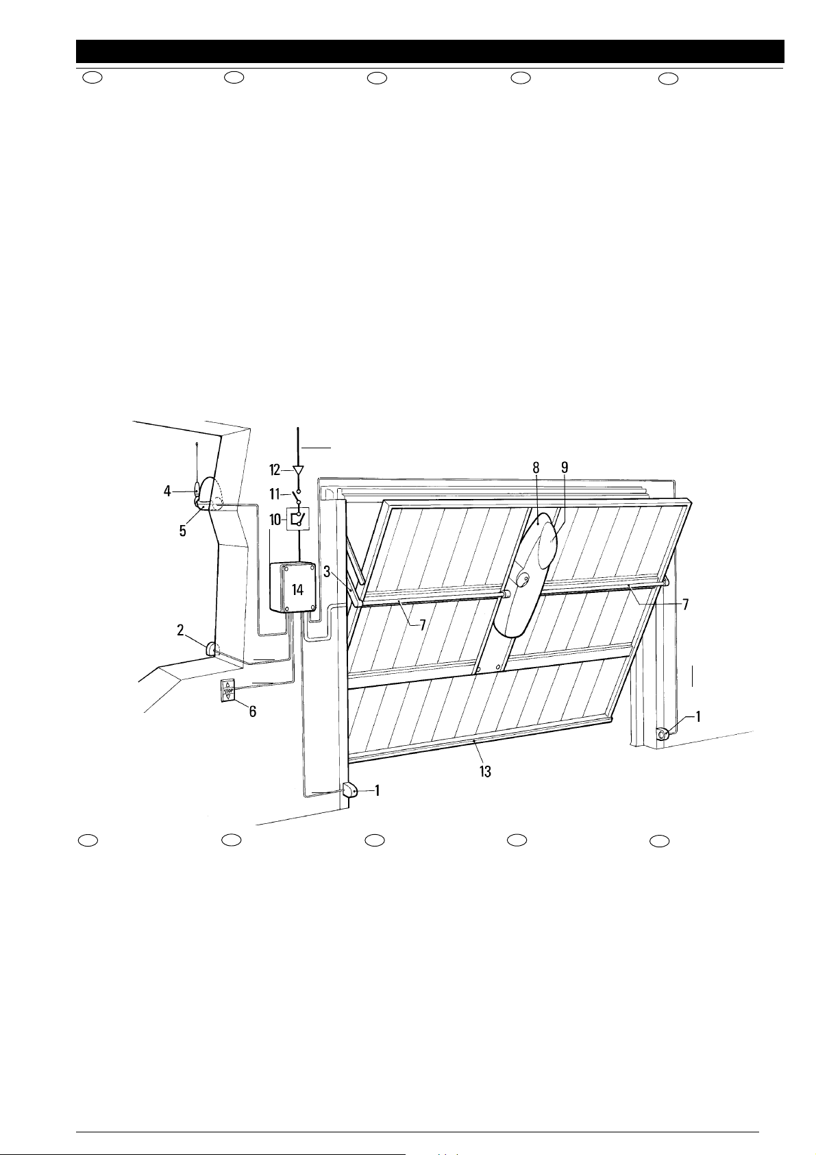
QUADRO D' INSIEME -
OVERALL PICTURE
3 x 1,5
2 x 1 RG 58
3 x 1
3 x 1
4 x 1
- CADRE GÉNÉRAL -
ÜBERSICHTZEICHNUNG
- ESQUEMA DE CONJUNTO
2 x 1
I
1) Coppia di fotocellule.
2) Selettore a chiave
o tastiera digitale.
3) Coppia di bracci
telescopici.
4) Antenna.
5) Lampeggiatore.
6) Pulsantiera interna.
7) Alberi di trasmissione.
8) Motoriduttore
9) Lampada di cortesia.
10) Interuttore differenziale.
11) Interuttore generale.
12) Linea di alimentazione.
13) Sensore pneumatico
14) Scatola di derivazione.
GB
1) Photocell pair
2) Key selector or
digital keypad
3) Pair of telescopic arms
4) Aerial
5) Flashing light
6) Internal push-button
panel
7) Drive shafts
8) Gearmotor
9) Courtesy light
10) Differential switch
11) Master switch
12) Power supply line
13) Pneumatic sensor
14) Connector block
F
1) Paire de cellules
photoélectriques
2) Sélecteur à clé et
clavier digital
3) Paire de bras
télescopiques
4) Antenne
5) Clignotant
6) Bouton de commande
interne
7) Arbre de transmission
8) Motoréducteur
9) Éclairage de
fonctionnement
10) Interrupteur différentiel
11) Interrupteur général
12) Ligne d’alimentation
13) Capteur pneumatique
14) Boîtier de dérivation
D
1) Paar Fotozellen
2) Wahlschalter mit
Schlüssel oder Tastfeld
3) Paar Teleskoparme
4) Antenne
5) Blinklampe
6) Inneres Tastfeld
7) Antriebswellen
8) Antrieb
9) Beleuchtung
10) Differentialschalter
11) Hauptschalter
12) Netzleitung
13) Pneumatiksensor
14) Verteilerdose
E
1 - Par de fotocélulas
2 - Selector de llave o
teclado digital
3 - Pareja de brazos
telescópicos
4 - Antena
5 - Luz intermitente
6 - Cuadro de pulsadores
interno
7 - Árboles de transmisión
8 - Motorreductor
9 - Lámpara de cortesía
10 - Interruptor diferencial
12 - Línea de alimentación
13 - Sensor neumático
14 - Caja de derivación
3
Page 4

OTTO
LIMITI D'IMPIEGO -
DIMENSIONI D'INGOMBRO -
LIMITS OF USE
DIMENSIONS
- LIMITES D'UTILISATION -
2,5
2,4
2,3
2,2
2,1
Altezza max. anta (m)
sì
basculante
debordante
- DIMENSIONS D’ENCOMBREMENT -
55
no
basculante
non debordante
EINSATZGRENZEN
RAUMBEDARF
- LIMITES DE EMPLEO
- DIMENSIONES
130
APPLICAZIONI TIPICHE -
TYPISCHE ANWENDUNGEN
I
Regolazione della frizione elettrica OT 21
La regolazione della coppia è affidata al trasformatore
incorporato. Vi sono 5 posizioni con indicazioni 30%÷
100% (Fig.11).
GB
Adjusting the electric clutch OT 21
The incorporated transformer regulates the torque.
There are 5 positions marked 30%
÷
100% (Fig. 11).
600
TYPICAL APPLICATIONS
- APLICACIONES HABITUALES
230
- APPLICATIONS TYPIQUES
102,5
135
179
F
RØglage de l’embrayage Ølectrique OT 21
Le rØglage du couple est assurØ par le transformateur
incorporØ. Il y a 5 positions avec indications 30%÷
100% (Fig. 11).
D
Einstellung der elektrischen kupplung OT 21
Die Einstellung des Drehmoments erfolgt durch den
integrierten Transformator. Es gibt fünf Positionen mit
der Anzeige 30% bis 100% (Abbildung 11).
E
Regulacion del embrague electrico OT 21
La regulacion del pares efectuada por eltransformador
incorporado. Se encuentran marcadas 5 posiciones
con indicaciones 30% ÷100% (Fig. 11).
4
Page 5

I
Due motori laterali.
Per porte superiori a 8 mq. si consiglia di montare due motoriduttori
lateralmente; collegati elettricamente in parallelo.
Two side motors.
GB
For doors larger than 8m
2
, you are advised to fit two gearmotors at
the sides electrically connected in parallel.
Deux moteurs latéraux.
F
Pour les portes supérieures à 8 m
2
, il est conseillé de monter deux
motoréducteurs (un de chaque côté) raccordés électriquement en
parallèle.
Zwei seitliche Motoren
D
Bei Toren mit einer Größe von über 8 m2 wird empfohlen, zwei
Antriebe seitlich zu montieren, die parallel geschaltet werden.
Dos motores laterales.
E
Para puertas con dimensiones superiores a los 8 m2, es
aconsejable montar dos motorreductores a los lados; conectados
eléctricamente en paralelo.
I
PORTA NON DEBORDANTE
Per automatizzare porte con altezza oltre i 2.50m utilizzare l’accessorio OTA51.
Altezza max portone con accessorio OTA15: 2700 mm
OTTO
GB
NON-PROJECTING DOOR
To automate doors higher than 2.50m, use the OTA51 accessory.
Max door height with OTA15 accessory: 2700 mm
F
PORTE NON DÉBORDANTE
Pour automatiser des portes d’une hauteur supérieures à 2,50 m,
utiliser l’accessoire OTA51.
Hauteur max. porte avec accessoire OTA15 : 2700 mm
NICHT AUSRAGENDES
D
VERSENKBARES TOR
Für die Automatisierung von Toren über 2,50 m Höhe Zubehör
OTA51 verwenden.
Max. Torhöhe mit Zubehör OTA15: 2700 mm
PUERTA ANGULAR
E
Para automatizar puertas con una altura de más de 2,50 m utilice
el accesorio OTA51.
Altura máx. del portón con accesorio OTA15: 2700 mm.
I
Porta snodata, con motore centrale.
GB
Jointed door with central motor.
F
Porte articulée avec moteur central
D
Falttor mit mittlerem Motor
E
Puerta articulada con motor central.
50 /100 mm.
5
Page 6

OTTO
I
POSIZIONAMENTO E SCELTA DEI
BRACCI TELESCOPICI
Posizionareilmotoriduttore con relativo supporto**, facendo in modo che l’asse di rotazione degli alberi di trasmissione, a basculante chiuso, si trovi circa 50 - 100 mm. piø
in basso rispetto al centro di rotazione della porta
basculante.
Qualoranon ci sia spaziosufficiente trabraccio disupporto
e parte fissa della porta, sarà neccessario, al fine di
evitarne l’incrocio, utilizzare i bracci curvi.
GB
POSITIONING AND CHOICE OF
TELESCOPIC ARMS
Position the gearmotor with support so that when the
pivoting door is closed, the rotation axis of the drive shafts
is approximately 50-100 mm lower than the centre of
rotation of the pivoting door.
If there is not sufficient space between the supporting arm
and fixed part of the door, curved arms must be used to
prevent crossing.
F
POSITIONNEMENT ET CHOIX DES
BRAS TÉLESCOPIQUES
50 / 100 mm.
Positionner le motorØducteur avec son support ** en
faisant en sorte que laxe de rotation des arbres de
transmission, avec la porte basculante fermØe, se trouve
environ 50 - 100 mm plus bas par rapport au centre de
rotation de la porte basculante.
Sil ny a pas suffisamment despace entre le bras de
supportet la partie fixede laporte, pourØviter lecroisement
il faut utiliser les bras courbes
D
POSITIONIERUNG UND WAHL DER
TELESKOPARME
Den Antrieb mit der entsprechenden Halterung**
ausrichten, so daß die Rotationsachse der Antriebswellen
bei geschlossenem Schwingtor sich 50 bis 100 mm
unterhalb des Rotationszentrums des Schwingtors
befinden.
Wenn zwischen dem Halterungsarm und dem festen Teil
des Tors nicht genügend Platz ist, ist zur Vermeidung von
Überkreuzungen die Verwendung von gebogenen Armen
erforderlich.
E
COLOCACIÓN Y ELECCIÓN DE LOS
BRAZOS TELESCÓPICOS
Colocar el motorreductor con su respectivo soporte** de
manera que el eje de rotación de los Ærboles de
transmisión, con elbasculante cerrado, seencuentreunos
50 o 100 mm. aproximadamente mÆs abajo del centro de
rotación de la puerta basculante.
En caso de que no hubiera espacio suficiente entre el
brazo del soportey la partefijade la puerta,serÆ necesario
utilizar brazos curvados, para evitar que se crucen.
50 / 100 mm.
I
** N.B.:
Assicurarsi, con l’ausilio di
una livella, che il tutto sia
perfettamente verticale.
Fissare il supporto al telaio,
tramite saldatura o viti adeguate.
6
GB
** N.B.
Using a spirit level, ensure
that everything is perfectly
vertical.
Fix the support to the frame
by welding or suitable
screws.
F
** N.B.:
A laide dun niveau à bulle,
sassurer que le tout est
parfaitement vertical. Fixer
le support au cadre avec
une soudure ou des vis
appropriØes.
D
** Anm.:
Mit Hilfe einer
Wasserwaage überprüfen,
ob alles vollkommen
waagerecht ist.
Die Halterung am Rahmen
anschweißen oder mit
geeigneten Schrauben
anschrauben.
E
** NOTA:
Comprobar con ayuda de
un nivel, que todo estØ
perfectamente vertical.
Fijar el soporte al bastidor
mediante soldadura y
tornillos adecuados.
Page 7

OTTO
DESCRIZIONE DI MONTAGGIO -
MONTAGEBESCHREIBUNG
OTA35
ASSEMBLY DESCRIPTION
- DESCRIPCIÓN DE MONTAJE
2
- DESCRIPTION DU MONTAGE
OTA37
1
6
3
5
4
I
1 -Motoriduttore.
2 -Staffa supporto motore.
3 -Albero di trasmissione
con supporto.
4 -Braccio dritto.
5 -Braccio curvo.
6 -Bussola.
GB
1 - Gearmotor
2 - Motor support bracket
3 - Drive shaft with support
4 - Straight arm
5 - Curved arm
6 - Bush
F
1 - Motoréducteur
2 - Profil de support moteur
3 - Arbre de transmission
avec support
4 - Bras droit
5 - Bras courbe
6 - Douille
D
1 - Antrieb
2 - Halterungsbügel Motor
3 - Antriebswelle mit
Halterung
4 - Gerader Arm
5 - Gebogener Arm
6 - Buchse
E
1 - Motorreductor
2 - Brida soporte del motor
3 - Árbol de transmisión
con soporte.
4 - Brazo recto.
5 - Brazo curvado.
6 - Casquillo
7
Page 8

OTTO
MANOVRA MANUALE DALL' INTERNO
MANUAL OPERATION FROM INSIDE
MANOEUVRE MANUELLE DE L’INTÉRIEUR
MANUELLE HANDHABUNG VON INNEN
MANIOBRA MANUAL DESDE EL INTERIOR
I
Ruotare in senso orario per sbloccare.
GB
Turn clockwise to release
F
Tourner dans le sens des aiguilles dune montre
pour dØbloquer
D
Zum Entsperren nach rechts drehen.
E
Girar en el sentido de las agujas del reloj para
desbloquear.
MANOVRA MANUALE DALL'ESTERNO - Accessorio opzionale
MANUAL OPERATION FROM OUTSIDE - Optional accessory
MANOEUVRE MANUELLE DE L’EXTÉRIEUR - Accessoire en option
MANUELLE HANDHABUNG VON AUSSEN - Auf Wunsch Zubehör
MANIOBRA MANUAL DESDE EL EXTERIOR - Accesorio opcional
I
1 -Cordino di sbocco.
2 -Registro.
3 -Staffa di supporto.
4 -Vite fissaggio cavo.
5 -Alberino di sblocco.
GB
1 - Release cord
2 - Register
3 - Supporting bracket
4 - Cable fixing screw
5 - Release shaft
F
1 - Cordon de dØblocage
2 - Écrou de rØglage
3 - Patte de support
4 - Vis de fixation câble
5 - Arbre de dØblocage
D
1 - Entblockungszug
2 - Registerschraube
3 - Halterungsbügel
4 - Befestigungsschraube Kabelzug
5 - Entblockungswelle
E
1 - Cordón de desbloqueo.
2 - Regulación.
3 - Brida de soporte.
4 - Tornillo de fijación del cable.
5 - Eje de desbloqueo.
8
Page 9

OTTO
KIT FINE CORSA - Accessorio opzionale
STROKE END KIT - Optional accessory
KIT MICROINTERRUPTEURS DE FIN DE COURSE - Accessoire en option
ENDSCHALTERSATZ - Sonderzubehör
EQUIPO DE FIN DE CARRERA - Accesorio opcional
Questo accessorio è composto da un set di due microinterruttori
comandati da due camme. Vanno fissati uno a destra e uno a sinistra del
motoriduttore e collegati alla centralina elettronica.
This accessory consists of a set of two microswitches controlled by
two cams. They must be fitted one on the right and one on the left of the
gearmotor and connected to the electronic control unit.
Cet accessoire est composé d’un jeu de deux microinterrupteurs
commandés par deux cames. Ils doivent être fixés un à droite et un à
gauche du motoréducteur et raccordés à la centrale électronique
Dieses Zubehörteil besteht aus einem Satz von zwei
Mikroschaltern, die von zwei Nocken betätigt werden. Einer wird rechts und
einer wird links von dem Antrieb montiert und sie werden an die
elektronische Steuereinheit angeschlossen.
Este accesorio está compuesto por una serie de dos
microinterruptores mandados por dos excéntricos. Se fijan uno a la
derecha y el otro a la izquierda del motorreductor y van conectados a la
centralita electrónica.
I
GB
F
D
E
I
GB F D E
ACCESSORI A
RICHIESTA
ACCESSORIES
ON REQUEST
ACCESSOIRES
SUR DEMANDE
AUF ANFRAGE
ERHÄLTLICHES
ZUBEHÖR
ACCESORIOS
A PEDIDO
9
Pz.
1
1
1
1
1
1
1
1
2
1
1
1
1
1
1
1
1
1
1
1
1
Code
PIÙ
OTA1
OTA30*
TRA-B- 1030
TRA-C- 1030*
OTA2*
OTA3*
OTA9*
OTA4
OTA5
OTA6
OTA7
OTA8
OTA10*
OTA11*
OTA12*
OTA16
TS*
OTA35*
OTA36*
OTA37*
Descrizione
Scheda espansione per
centrale elettronica
Centrale di ricambio solo
scheda per OT 21
Centrale di ricambio solo
scheda per OT 31
Tr asformatore di ricambio
per OT 21
Tr asformatore di ricambio
per OT 31
Staffa supporto motore L
= 1250 mm.
Staffa supporto motore L
= 2000 mm.
Staffa supporto motore L
= 520 mm.
Coppia alberi
trasmissione L = 1500
mm. con supporti
Braccio dritto telescopico
Braccio curvo telescopico
Bussola
Coppia alberi
trasmissione L = 2000
mm.
Kit per fine corsa
Kit per sblocco
dall’esterno con cordino
metallico
Kit per sblocco
dall’esterno con nottolino
a chiave
Braccio diritto con
bussola saldata
Tabella segnaletica
Braccio diritto telescopico
per tubi quadri
Coppia dispositivi di rinvio
per bracci OTA 35
Tubo quadro di
trasmissione 25x25
L = 3000 mm.
Description
Espansion card
Electronic for OT21
Electronic for OT31
Tr ansformer for OT 21
Tr ansformer for OT 31
Motor support bracket
L = 1250 mm.
Motor support bracket
L = 2000 mm.
Motor support bracket
L = 520 mm.
Pair of propeller shafts
L = 1500 mm.
Straight telescopic arm
Curved telescopic arm
Bush
Pair of propeller shafts
L = 2000 mm.
Kit for limit switch
Kit for unlocking from
the outside with a
metal cord
Kit for unlocking from
the outside with a lock
and key
Straight arm with
welded bush
Signalisation table
Straight telescopic arm
for OT 31
Pair of arm return
devices OTA 35
Square transmission
pipe 25x25 L = 3000
mm.
Description
Carte expansion
Centrale électranique
pour OT21
Centrale électranique
pour OT31
Tr ansformateur pour OT
21
Tr ansformateur pour OT
31
Patte de support
moteur L = 1250 mm.
Patte de support
moteur L = 2000 mm.
Patte de support
moteur L = 520 mm.
Paire arbres de transmission L = 1500 mm.
Bras droit télescopique
Bras courbe
télescopique
Douille
Paire arbres de transmission L = 2000 mm.
Kit pour microinterrupteur de fin de course
Kit pour déblocage de
l’extériur avec câble
métallique
Kit pour déblocage de
l’extériur avec cylindre à
clé
Bras droit avec douille
soudée
Ta bleau signalétique
Bras droit télescopique
pour OT 31
Paire de dispositifs de
renvoi pour bras OTA 35
Tube carré de transmission 25x25
L = 3000 mm.
Beschreibung
Erweiteryngskarte
Elektronische
Steuerzentrale für OT21
Elektronische
Steuerzentrale für OT31
Tr ansformator für
OT 21
Tr ansformator für
OT 31
Motortragbügel
L = 1250 mm.
Motortragbügel
L = 2000 mm.
Motortragbügel
L = 520 mm.
Paar Antriebswellen
L = 1500 mm.
Gerader Teleskoparm
Gebogener
Teleskoparm
Buchse
Paar Antriebswellen
L = 2000 mm.
Satz für Endschalter
Satz für Entriegelung
von außen mit
Metallschnur
Satz für Entriegelung
von außen mit Schloss
und Schlüssel
Gerader Arm mit
geschweißter Buchse
Beschilderungstabelle
Gerader Teleskoparm
für OT 31
Paar Antriebsvorrichtungen
für Arme OTA 35
Vierkantiges
Antriebsrohr 25x25
L = 3000 mm.
Descripción
Tarjeta de expansión
Central electrónica
para OT21
Central electrónica
para OT31
Tr ansformador para
OT 21
Tr ansformador para
OT 31
Estribo de soporte del
motor L =1250 mm.
Estribo de soporte del
motor L = 2000 mm.
Estribo de soporte del
motor L = 520 mm.
Par de árboles de transmisión L = 1500 mm.
Brazo telescópico
recto
Brazo telescópico
curvo
Casquillo
Par de árboles de transmisión L = 2000 mm.
Kit para microinterruptor
Kit para desbloqueo
desde afuera con
cordel metálico
Kit para desbloqueo
desde afuera con
cerradura con llave
Brazo recto con
casquillo soldado
Ta bla de las señles
Brazo telescópico
recto para OT 31
Par de dispositivos de
transmisión para brazos
Tubo cuadrado de
transmisión 25x25
L = 3000 mm.
I
GB F D E
* Accessori solo per kit OTTO-KCE - * Accessories for the OTTO-KCE kit only - * Accessoires seulement pour kit OTTO-KCE
* Zübehör nur für OTTO-KCE - * Accesorios sólo para kit OTTO-KCE.
Page 10

0TTO
I
CATALOGO RICAMBI
F
CATALOGUE DES RECHANGES
GB
SPARE PARTS CATALOGUE
D
ERSATZTEILKATALOG
E
CATÁLOGO DE RECAMBIOS
10
Page 11

OTTO
Pos.
BMGB 4567
1
BPCO 4540
2
BMMO 4540
3
BPVC 4541
4
CLOT 5320
5
GOR-4 5501
6
L1 6811
7
MO-C 2640
8
MPP 2601
9
PECR50B 4670
10
PEDS501 4650
11
PMCBR1 4630
12
PMCSE25 4630
13
PMCU3 4630
14
PMCU102 4630
15
PMDKI 4610
16
PMDKI 4610
17
PECR50B 4670
18
PMDKI 4610
19
PMDKI 4610
20
V2.9X19 5101
21
PMC66B 4630
22
PMD0033 4610
23
BPBS 4540
24
10U450A 0727
25
OTA1
26
BMMP 4567
27
BPME1 4540
28
CGU8B 5310
29
C3VF 2015
30
PMCSE15 4630
31
EMRO 4870
32
MMCOI 2620
33
PMCAC1 4630
34
EOT21 4870
35
TRA-B 1030
36
MPFB2 2601
37
EF 4870
38
MICROI-C 1617
39
PMDPS 4610
40
PMD0014D 4610
41
PMD0014C 4610
42
PMDPS1 4610
43
G6X6 5123
44
V2.9X13 5101
45
V3X12 5102
46
V4.2X9.5 5101
47
V4.8X13 5101
48
V4.8X13-A 5101
49
V6.3X19 5101
50
V6.3X25 5101
51
V2.9X9.5-A 5101
52
PBME 4540
53
PMD0231 4610
54
Code
I
Descrizione
Guscio alluminio
Coperchio motore
Maniglia
Vetrino coperchio
Cablaggio lampada
Guarnizione
Lampada
Molla di sblocco
Portalampade
Rotore motore
Statore
Bronzina 12x16x12
Anello seeger ∆25
Cuscinetto 6005 ZZ
Cuscinetto 6003 2RS
Albero intermedio
Albero iniziale portacorona
Albero motore
Albero d’uscita scanalato
Corona elicoidale
Vite 2.9x19
Chiavetta per sblocco
Perno di sblocco
Base scatola centrale
Condensatore
Scheda comando
Collare
Cuffiette coprimozzo
Guaina PVC
Connettore Alex
Anello seeger ø15
Etichetta morsettiera
Occhiello isolato
Anello compensatore
Etichetta motoriduttore
Trasformatore
Fascetta
Etichetta “Forza”
Microinterruttore
Astina di sblocco
Distanziale
Eccentrico sblocco
Perno astina sblocco
Grano M6x6
Vite autofil. 2.9x13
Vite 3x12
Vite autofil. 4.2x9.5
Vite autofil. 4.8x13
Vite autofil. 4.8x13
Vite autofil. 6.3x19
Vite autofil. 6.3x25
Vite autofil. 2.9x9.5
Eccentrici di finecorsa
Cuffietta
GB
Description
Aluminium shell
Motor cover
Handgripp
Glass cover
Lamp wiring
Gasket
Lamp
Release spring
Bulb socket
Rotore motore
Stator
Bearing 12x16x12
Circlip Ø25
Ball bearing 6005 ZZ
Ball bearing 6003 2RS
Intermediate schaft
Initial ring gear shaft
Drive shaft
Splined output shaft
Spiral ring gear
2.9x19 screw
Release key
Release pin
Base of central unit box
Capacitor
Control card
Collar
Hub-cap
PVC sheath
Alex connector
Snap ring ø15
Terminal board label
Insulated slot
Compensator ring
Gearmotor label
Transformer
Clamp
“Force” label
Microswitches
Unlock rod
Spacer
Unlock eccentric
Unlock rod pin
M6x6 threa. Dowel
2.9x13 screw
3x12 screw
4.2x9.5 screw
4.8x13 screw
4.8x13 screw
6.3x19 screw
6.3x25 screw
2.9x9.5 screw
Limit swich cams
Hub-cap
F
Description
Coque aluminium
Couvercle moteur
Poignée
Hublot couvercle
Câblage lampe
Joint
Ampoule
Ressort de déblocage
Douille lampe
Rotor moteur
Stator
Douille bronze 12x16x12
Bague seeger Ø25
Roulement 6005 ZZ
Roulement 6003 2RS
Arbre intermédiaire
Arbre initial
Arbre moteur
Arbre avec extremite sc.
Couronne hélicoïdale
Vis 2.9x19
Clavette pour déblocage
Pivot de deblocage
Base boîtier centrale
Condensateur
Carte commande
Collier
Soufflets protége-moyeu
Gaine PVC
Connecteur Alex
Bague seeger ø15
Etiquette bornier
Oeillet isolé
Bague compensatrice
Etiquette motoreducteur
Transformateur
Collier de serrage
Etiquette “Force”
Microinterrupteurs
Tige de deblocage
Entretoise
Excentrique de débl.
Goujon tige déblocage
Goujon fileté M6x6
Vis 2.9x13
Vis 3x12
Vis 4.2x9.5
Vis 4.8x13
Vis 4.8x13
Vis 6.3x19
Vis 6.3x25
Vis 2.9x9.5
Excentr. de fin de course
Soufflets
D
Beschreibung
Aluminiumschale
Motordeckel
Griff
Fensterchen Deckel
Verkabelung Lampe
Dichtung
Lampe
Entblockungsfeder
Fassung
Rotor motor
Stator
Bronzelager 12x16x12
Seegering Ø25
Lager 6005 ZZ
Lager 6003 2RS
Zwischenwelle
Eingangswelle / Krone
Motorwelle
Ausgangswelle mit Kehle
Schneckenkrone
Schraube 2.9x19
Entblockungsschlüssel
Entblockungsstift
Grundgestell Gehäuse ste.
Kondensator
Steuerungsplatine
Stellring
Nabenhauben
PVC Mantel
Alex verbinder
Seeger-Ring ø15
Klemmenbrettetikett
Schlitz
Ausgleichsring
Getriebemotoretikett
Transformator
Schelle
Etikett “Kraft”
Mikroschalter
Entriegelungsstange
Distanzstück
Entriegelungsnocken
Zapfen für Entriegelungsstange
Gewindestift M6x6
Schraube 2.9x13
Schraube 3x12
Schraube 4.2x9.5
Schraube 4.8x13
Schraube 4.8x13
Schraube 6.3x19
Schraube 6.3x25
Schraube 2.9x9.5
Anschlagnocken
Nabenhauben
Casco de aluminio
Tapa del motor
Manilla
Vidrio de la tapa
Cableado làmpara
Junta
Làmpara
Resorte de desbloqueo
Portalàmparas
Rotor motor
Estator
Casquillo 12x16x12
Anillo seeger Ø25
Cojinete 6005 ZZ
Cojinete 6003 2RS
Arbol intermedio
Arbol inicial portacorona
Eje motor
Arbol salida acanalado
Corona helicoidal
Tornillo 2.9x19
Chaveta para desbloqueo
Perno de desbloqueo
Base para caja central
Condensator
Tarjeta de mando
Collar
Envolturas tapacubos
Vaina de PVC
Connector Alex
Arandela seeger ø15
Etiqueta del tablero de bornes
Argolla aislada
Anillo compensador
Etiqueta motorreductor
Transformador
Abrazadera
Etiqueta “Fuerza”
Microinterruptores
Varilla de desbloqueo
Arandela distanciadora
Excéntrica de desbloqueo
Perno varilla de desbloqueo
Pasador roscado M6x6
Tornillo 2.9x13
Tornillo 3x12
Tornillo 4.2x9.5
Tornillo 4.8x13
Tornillo 4.8x13
Tornillo 6.3x19
Tornillo 6.3x25
Tornillo 2.9x9.5
Excéntricas de final de carrera
Envolturas
E
Descripción
I
Per i ricambi N° 19 - 26 - 53, specificare il modello di "OTTO".
GB
For parts no. 19 - 26 - 53, please specify the OTTO model.
F
Pour les pièces de rechange n° 19 - 26 - 53, préciser le modèle de “OTTO”.
D
Bei den Ersatzteilen 19 - 26 - 53, immer das Modell von “OTTO” angeben.
Para las piezas de repuesto N° 19 - 26 - 53, especificar el modelo de “OTTO”.
E
11
Page 12

IMPORTANTE / IMPORTANT
Compilare ad installazione avvenuta e trattenere ad uso garanzia.
To be completed after installation and kept for use as a warranty
Dati cliente /
Nome e cognome ....................................................
Name and surname
Client data
Telefono ....................................................................
Telephone
Indirizzo ..........................................................................................................................................................
Address
Apparecchiatura tipo ...................................................
Appliance type
Data di installazione ....................................................
Installation date
Installatore ..................................................................
Installer
Indirizzo .....................................................................
Address
Descrizione materiale installato /
Description of the components installed
Matricola ...................................................................
No. Code
Termine garanzia ........................................................
Warranty expiry date
Ditta ..........................................................................
Messrs
Telefono .....................................................................
Telephone
Centrale di comando Radio Dispositivi di sicurezza Note
Control box Radio Safety devices Notes
Controlli periodici / Periodical check-ups
Data /
Data /
Data /
Data /
Date
................................... Descrizione /
Date
................................... Descrizione /
Date
................................... Descrizione /
Date
................................... Descrizione /
Description
Description
Description
Description
............................................................................
............................................................................
............................................................................
............................................................................
Da compilare in caso di anomalia (inviare fotocopia della pagina allegandola all'attuatore in riparazione)
To fill in case of defect
Difetto segnalato /
(send copy of the page enclosed with the actuator to be repaired)
Defect
.................................................................................................................................
.......................................................................................................................................................................
Parte riservata alla MOVO per comunicazioni al cliente
Space reserved for MOVO to communicate with the Clients
Data registrazione ..................................Data riparazione............................... N. Riparazione .....................
Date of registration Repair date Repair number
Parti sostituite .............................................................................................................................................
Parts replaced
Note /
Note
....................................................................... Firma tecnico /
Technician signature
.........................................................................................
......................................................................................... .................................................................
A termini di legge ci riserviamo la proprietà di questo manuale con divieto di riprodurlo o di renderlo comunque noto a terzi
o a ditte concorrenti senza nostra autorizzazione.
carta riciclata 100% recycled paper 100% papier recycle 100% 100% Altpapier 100% papel reciclado
Nice SpA
Oderzo TV Italia
Via Pezza Alta, 13 Z.I. Rustignè
Tel. +39.0422.85.38.38
Fax +39.0422.85.35.85
info@niceforyou.com
Nice Belgium
Leuven (Heverlee) B
Tel. +32.(0)16.38.69.00
Fax +32.(0)16.38.69.01
nice.belgium@belgacom.net
Nice España Madrid E
Tel. +34.9.16.16.33.00
Fax +34.9.16.16.30.10
kamarautom@nexo.es
Nice France Buchelay F
Tel. +33.(0)1.30.33.95.95
Fax +33.(0)1.30.33.95.96
info@nicefrance.fr
Nice Polska Pruszków PL
Tel. +48.22.728.33.22
Fax +48.22.728.25.10
nice@nice.com.pl
www.niceforyou.com
ISTOT 4865 REV. 011
 Loading...