

Page 1
MOF-MOFO
photocells
Introduction
The MOON series photocell is a safety
device that can be used with automatic gate
and door openers to detect the presence of
obstacles between the transmitter (TX) and
the receiver (RX).
The effective opening angle of the photocell may be
reduced to ±5° as required by the IEC 61496-2
standard. This angle is guaranteed for TX-RX
distances greater than 1m.
Nice reserves the right to make any modifications to the
products as it sees fit.
Introduzione
La fotocellula della serie MOON, è un
dispositivo di sicurezza utilizzabile in impianti
di cancelli e porte automatiche per rilevare la
presenza di ostacoli sull’asse ottico fra
trasmettitore (TX) e ricevitore (RX).
La fotocellula è predisposta per la riduzione a ±5°
dell’effettivo angolo di apertura come richiesto dalla
norma IEC 61496-2. La riduzione dell’angolo è
garantita per distanze TX-RX superiori a 1m.
Nice si riserva di apportare modifiche migliorative ai
prodotti.
Introduccion
La fotocélula de la serie MOON es un
dispositivo de seguridad que se puede
utilizar en instalaciones de cancelas y
puertas automáticas, para detectar la
presencia de obstáculos en el eje óptico
entre el transmisor (TX) y el receptor (RX).
La fotocélula está preajustada para la reducción a ±5°
del ángulo efectivo de apertura, según los requisitos de
la norma IEC 61496-2. La reducción del ángulo está
garantizada para distancias TX-RX por encima de 1m.
Nice se reserva el derecho de realizar en sus productos
las modificaciones que considerará oportunas.
Introduction
La photocellule de la série MOON est un
dispositif de sécurité utilisable dans des
installations avec portes et portails
automatisés pour détecter la présence
d’obstacles sur l’axe optique entre émetteur
(TX) et récepteur (RX).
La photocellule est prévue pour la réduction à ±5° de
l’angle d’ouverture effectif conformément à la norme
IEC 61496-2. La réduction de l’angle est garantie
pour des distances TX-RX supérieures à 1m.
Nice se réserve le droit d’apporter à tout instant les
modifications qu’elle judgera utiles.
Einleitung
Die Photozelle der Serie MOON ist eine
Sicherheitsvorrichtung, die in Anlagen mit
automatischen Toren und Türen verwendet
werden kann, um Hindernisse auf der
optischen Achse zwischen Sender (TX) und
Empfänger wahrzunehmen (RX).
Wie von der Norm IEC 61496-2 gefordert, ist die
Photozelle für die Reduzierung des effektiven
Öffnungswinkels auf ±5° vorbereitet. Die Reduzierung
des Winkels wird für Abstände zwischen TX und RX
gewährleistet, die größer als 1 m sind.
Druckfehler vorbehalten, technische Änderungen der
Produkte im Zuge der Weiterentwicklung vorbehalten.
Przedmowa
Fotokomórka z serii MOON jest urządzeniem
zabezpieczającym do zastosowania w
bramach i drzwiach automatycznych w celu
odczytania obecność przeszkód w zasięgu
promienia optycznego pomiędzy nadajnikiem
(TX) i odbiornikiem (RX).
Fotokomórka przystosowana jest do redukcji o +/-5˚
efektywnego kąta otwarcia, tak jak jest to wymagane w
normie IEC 61496-2. Redukcja kąta zagwarantowana
jest dla odległości TX-RX powyźej 1m.
Nice rezerwuje sobie prawo wprowadzenia jakiejkolwick
zmiany w produktach, którą uzna za konieczną.
GB F E
I D PL
moon
Page 2
1 2
NC
COM
NO
NC
COM
NO
TXRX
TXRX
A
B
BA
AB
ABAB
BA BA
12345 12
12345 12
3
4
4a
4b
3b
3a
1a
1b
24 Vac
24 Vcc
SYNC.
12V
+
-
+10m
LS
100-A
099-A
LS
12V
TX RX
TXRX
12345 12
+- +-
NC
COM
NO
Page 3
6
5
5a
5b
5c
5d
7
L
A
B
RX RX
Page 4

Technical features
Type
Safety device for automatic doors and gates
Technology used
Direct TX-RX obstruction with an impulse-modulated
infrared beam
Max. range
15m (30m with jumper + “10m.” with cut jumper)
Range can be reduced by 50% in bad weather
conditions: fog, rain, dust, etc.
Range can be reduced by 30% when using the cone
for reducing the actual opening angle
Power input
without jumper 24 Vac/Vdc limits 18-35 Vdc, 15-28 Vac
with jumper 12 Vac/Vdc limits 10-18 Vdc , 9-15 Vac
Max. power consumption
25 mA RX, 30mA Tx = 55 mA per pair
Operating temperature
from -20 to +60 °C according to EN 600068-2-1 / EN
600068-2-2 standards
Level of protection
IP55 according to EN 60529 standard
Output relay contact
Max. 500mA and 48V direct or alternating current
Lifetime of contact
> 600,000 AC11 or DC11 operations according
to NFP 25-363 standard
Response time
< 30 ms according to IEC 61496-2 and NFP 25-363
standards
RX detection angle
8° ± 25% with reducing cone, according to IEC
61496-2 standard approx. 20° without reducing cone
Angle of TX beam
20° ± 25%
Detection capacity
Opaque objects with a size of ≥ 50 mm and maximum
speed of 1.6 m/s.
Warnings Please read the instructions
carefully before installing the product, improper
use or an error in connection could jeopardise the
safety or correct operation of the device.
•This photocell may only be used to detect direct
interruptions between TX and RX; it may not be
reflected.
•Fix the photocell on a hard, vibration-free surface.
•In order to obtain an “ESPE type 2” safety device, the
photocell must be connected to central units fitted
with “fototest”, or at least 2 devices must be used for
the area to protect.
•Use conductors that are large enough to cope with
the required current and make sure the overload cut-out
located up-line from the safety devices is suitable sized.
•Make sure that the power input corresponds to the
values shown in the TECHNICAL FEATURES.
Servicing The photocells do not require any special
servicing, but routine maintenance must be carried out
at least every six months in order to check the state of
the device (presence of humidity, oxidation, etc.), clean
the outer casing and the lenses and test as shown in
the above paragraph.
These photocells have been designed to work in
normal conditions for at least 10 years; from then on,
maintenance work should be carried out more
frequently.
Disposal This product is made from various kinds
of material, some of which can be recycled.
Make sure you recycle or dispose of the product in
compliance with current laws and bye-laws.
Caractéristiques techniques
Typologie
dispositif de sécurité pour portes et portails
automatisés
Technologie adoptée
Interpolation directe TX-RX avec rayon infrarouge
modulé à impulsions
Portée maximum
15 m (30 m avec shunt +”10m.” coupé)
La portée peut se réduire de 50% en présence de
phénomènes atmosphériques: brouillard, pluie,
poussières, etc.
La portée peut se réduire de 30% quand on insère le
cône pour la réduction de l’angle d’ouverture.
Alimentation
sans shunt 24 Vac/Vcc limites 18-35 Vcc, 15-28 Vac
avec shunt 12 Vac/Vcc limites 10-18 Vcc, 9-15 Vac
Absorption maximale
25 mA RX, 30 mA TX = 55 mA par paire
Température de fonct.
de –20 à +60 °C selon les normes EN 600068-2-1 /
EN 600068-2-2
Indice de protection
IP55 selon la norme EN 60529
Contact relais de sortie
Max. 500 mA et 48V courant continu ou alternatif
Durée contacts
> à 600.000 interventions AC11 ou DC11 selon
la norme NFP 25-363
Temps de réponse
< à 30 ms selon les normes IEC 61496-2 et NFP 25-363
Angle de détection RX
8° ± 25% avec cône de réduction, selon la norme
IEC 61496-2 20° environ sans cône de réduction
Angle rayon émis TX
20° ± 25%
Capacité de détection
Objets opaques avec dimensions ≥ 50 mm et vitesse
maximum de 1,6 m/s.
Recommandations
Il est opportun de lire
attentivement les instructions avant d’effectuer
l’installation, l’utilisation impropre ou une erreur de
connexion pourraient compromettre la sécurité ou le
fonctionnement correct du dispositif de sécurité.
•La photocellule doit fonctionner exclusivement par
interpolation directe TX-RX, son emploi par réflexion est
interdit.
•La photocellule doit être fixée de manière permanente
sur une surface rigide et exempte de vibrations.
•Pour obtenir un dispositif de sécurité “ESPE type 2” la
photocellule doit être connectée à des centrales avec test
de la photocellule ou bien, il faut utiliser 2 dispositifs de la
zone à protéger.
•Pour les connexions électriques, utiliser des
conducteurs en mesure de supporter les courants requis
et dimensionner correctement le dispositif de protection
contre les surcharges situé en amont des dispositifs de
sécurité.
•S’assurer que l’alimentation correspond aux valeurs
indiquées dans le tableau CARACTÉRISTIQUES
TECHNIQUES.
Maintenance
Les photocellules ne nécessitent pas
de précautions particulières mais il faut effectuer une
maintenance programmée au moins tous les 6 mois au
cours de laquelle on doit vérifier leur état (présence
d’humidité, oxydes, etc.), effectuer le nettoyage du boîtier
et des lentilles et refaire l’essai du dispositif comme le
décrit le paragraphe précédent.
Les photocellules ont été étudiées pour fonctionner dans
les conditions normales pendant au moins 10 ans, il est
donc bon d’intensifier la fréquence de la maintenance
une fois cette période écoulée.
Mise au rebut
Ce produit est constitué de matériaux
divers, certains d’entre eux peuvent être recyclés.
Informez-vous sur les systèmes de recyclage ou de mise
au rebut du produit et respectez les normes locales en
vigueur.
Caratteristiche tecniche
Tipologia
dispositivo di sicurezza per cancelli e porte
automatiche
Tecnologia adottata
Interpolazione diretta TX-RX con raggio infrarosso
modulato ad impulsi
Portata massima
15m (30m con ponticello + “10m.” tagliato)
La portata si può ridurre del 50% in presenza di
fenomeni atmosferici: nebbia, pioggia, polvere ecc.
La portata si può ridurre del 30% quando viene inserito
il cono di riduzione dell’angolo di apertura.
Alimentazione
senza ponticello 24 Vac/Vcc limiti 18-35 Vcc,15-28Vac
con ponticello 12 Vac/Vcc limiti 10-18 Vcc , 9-15 Vac
Assorbimento massimo
25 mA RX, 30mA TX = 55 mA per coppia
Temperatura di funzionamento
da –20 a +60 °C secondo norme EN 600068-2-1
EN 600068-2-2
Grado di protezione
IP55 secondo norma EN 60529
Contatto relè di uscita:
Max 500mA e 48V corrente continua o alternata
Durata contatti
> a 600.000 interventi AC11 o DC11 secondo norma
NFP 25-363
Tempo di risposta
< a 30ms secondo norme IEC 61496-2 ed NFP 25-363
Angolo di rilevazione RX
8° ± 25% con cono di riduzione, secondo norma
IEC 61496-2, 20° circa senza cono di riduzione
Angolo raggio emesso TX
20° ± 25%
Capacità di rilevamento
Oggetti opachi con dimensioni ≥ 50 mm con velocità
massima di 1,6 m/s.
Avvertenze È opportuno leggere
attentamente le istruzioni prima di eseguire
l’installazione: l’uso improprio o un errore di
collegamento potrebbe pregiudicare la sicurezza o il
corretto funzionamento del dispositivo.
•La fotocellula deve funzionare esclusivamente per
interpolazione diretta TX-RX; è vietato l’uso per
riflessione.
•La fotocellula va fissata in modo permanente su una
superficie rigida e senza vibrazioni.
•Per ottenere un dispositivo di sicurezza “ESPE tipo 2”
la fotocellula deve essere collegata a centrali dotate di
fototest, oppure si devono utilizzare almeno
2 dispositivi per zona da proteggere.
•Utilizzare per i collegamenti elettrici conduttori in
grado di sopportare le correnti richieste e
dimensionare adeguatamente il dispositivo di
protezione contro le sovracorrenti posto a monte dei
dispositivi di sicurezza.
•Accertarsi che l’alimentazione corrisponda ai valori
riportati nella tabella CARATTERISTICHE TECNICHE.
Manutenzione Le fotocellule non necessitano di
accorgimenti particolari, ma è necessaria una
manutenzione programmata almeno ogni 6 mesi nella
quale venga verificato lo stato delle stesse (presenza di
umidità, ossidi, ecc.), venga quindi eseguita la pulizia
dell’involucro esterno e delle lenti, e rieseguito
il collaudo come descritto al paragrafo precedente.
Le fotocellule sono state studiate per funzionare in
condizioni normali almeno 10 anni, è quindi opportuno
intensificare la frequenza di manutenzione trascorso
questo periodo.
Smaltimento Questo prodotto è costituito da
varie tipologie di materiali , alcuni possono essere
riciclati.
Informatevi sui sistemi di riciclaggio o smaltimento del
prodotto attenendosi alle norme di legge vigenti
a livello locale.
GB
F
I
Page 5

Technische eigenschaften
Ty p
Sicherheitsvorrichtung für automatische Tore und Türen
Angewandte Technologie
Direkte Interpolation von TX und TX über durch Impulse
modulierten Infrarotstrahl
Max. Reichweite
15m (30m mit Brücke + “10m.” mit
durchgeschrittener Brücke)
Die Leistung kann bei atmosphärischen Phänomenen
wie Nebel, Regen, Staub usw. um 50% reduziert
werden. Die Leistung kann um 30% reduziert werden,
wenn der Reduzierungstrahl der Ôffnungswinkel
einfügen wird.
Speisung
Vacohne Brücke 24 Vac/Vcc Grenzen 18-35 Vcc,15-28 Vac
mit Brücke 12 Vac/Vcc Grenzen 10-18 Vcc , 9-15
Max. Leistungsaufnahme
25 mA RX, 30mA Tx = 55 mA pro Paar
Betriebstemperatur
von –20 bis +60 °C gemäß EN 600068-2-1
EN 600068-2-2
Schutzart
IP55 gemäß EN 60529
Ausgangsrelaiskontakt
Max. 500mA und 48V Gleichstrom oder Wechselstrom
Kontaktedauer
> als 600.000 Auslösungen von AC11 oder DC11
gemäß NFP 25-363
Ansprechzeit
< als 30ms gemäß IEC 61496-2 und NFP 25-363
Erfassungswinkel von RX
8° ± 25% mit Reduzierkegel, gemäß IEC 61496-2 ca.
20° ohne Reduzierkegel
Von TX abgegebener Strahlwinkel
20° ± 25%
Erfassungsvermögen
Matte Gegenstände mit Abmessungen von ≥ 50 mm
und mit Höchstgeschwindigkeit von 1,6 m/s.
Hinweise Vor dem Einbau sollten die
Anweisungen genau gelesen werden;
unsachgemäßer Gebrauch oder ein
Anschlussfehler könnten die Sicherheit und den
korrekten Betrieb der Sicherheitsvorrichtung
beeinträchtigen.
•
Die Photozelle darf ausschließlich durch direkte
Interpolation zwischen TX und TX funktionieren, der
Gebrauch durch Reflexion ist verboten.
•
Die Photozelle muss bleibend auf einer festen und
vibrationsfreien Fläche befestigt werden.
•
Um eine Sicherheitsvorrichtung “ ESPE Typ 2” zu
erhalten, muss die Photozelle an Zentralen mit
Fototest angeschlossen werden, oder es müssen
mindestens 2 Vorrichtungen für jede zu schützende
Zone benützt werden.
•
Für die elektrischen Anschlüsse Leiter verwenden, die
für die erforderlichen Stromwerte geeignet sind, und
die Schutzvorrichtung gegen Überströme vor den
Sicherheitsvorrichtungen entsprechend bemessen.
•
Sicherstellen, dass die Stromversorgung mit den in
der Tabelle TECHNISCHE EIGENSCHAFTEN
angegebenen Werten übereinstimmt.
Wartung Die Photozellen bedürfen keiner
besonderen Eingriffe, mindestens alle 6 Monate ist
aber eine programmierte Wartung nötig, bei der ihr
Zustand überprüft wird (Vorhandensein von
Feuchtigkeit, Roststellen, usw.), dann müssen das
Außengehäuse und die Linsen gereinigt werden, und
die Prüfung wie oben beschrieben muss erneut
durchgeführt werden.
Die Photozellen wurden konstruiert, um bei normalen
Bedingungen mindestens 10 Jahre lang zu
funktionieren, nach dieser Zeit sollte die Wartung
häufiger ausgeführt werden.
Entsorgung Dieses Produkt besteht aus
verschiedenen Werkstoffen, von denen einige
wiederverwertet werden können.
Informieren Sie sich über die Recycling- oder
Entsorgungssysteme des Produktes und halten Sie
sich an die örtlich gültigen Gesetzesverordnungen.
Características técnicas
Tipología
dispositivo de seguridad para cancelas y puertas
automáticas
Tecnología adoptada
Interpolación directa TX-RX con rayo infrarrojo
modulado por impulsos
Alcance máximo
15m (30m con conexión puente + “10m.” cortada)
El alcance se puede reducir del 50% en presencia de
fenómenos atmosféricos como niebla, Iluvia, polvo, etc.
El alcance se puede reducir del 30% cuando se monta
el cono para la reducción del ángulo efectivo de
apertura.
Alimentación
sin conexión puente 24 Vca/Vcc límites
18-35 Vcc,15-28 Vca
con conexión puente 12 Vca/Vcc límites
10-18 Vcc, 9-15 Vca
Absorción máxima
25 mA RX, 30mA Tx = 55 mA por par
Temperatura de func.
desde –20 hasta +60 °C según normas
EN 600068-2-1 / EN 600068-2-2
Grado de protección
IP55 según normas EN 60529
Contacto relé de salida
Máx 500mA y 48V corriente continua o alterna
Duración contactos
> a 600.000 operaciones AC11 o DC11, según norma
NFP 25-363
Tiempo de respuesta
< a 30ms según norma IEC 61496-2 y NFP 25-363
Ángulo de detección RX
8° ± 25% con cono de reducción, según norma
IEC 61496-2 20° aprox. sin cono de reducción
Ángulo rayo emitido TX
20° ± 25%
Capacidad de detección
Objetos opacos con dimensiones ≥ 50 mm
con velocidad máxima de 1,6 m/s.
Advertencias Es conveniente leer
atentamente las instrucciones antes de la
instalación; el uso impropio o un error de conexión
podría perjudicar la seguridad y el funcionamiento
correcto del dispositivo de seguridad.
•
La fotocélula debe funcionar exclusivamente por
interpolación directa TX-RX, está prohibido el uso por
reflexión.
•
La fotocélula se fija permanentemente en una
superficie rígida y sin vibraciones.
•
Para obtener un dispositivo de seguridad “ESPE tipo
2” la fotocélula se debe conectar a centrales equipadas
con fototest, o bien se deben emplear 2 dispositivos,
como mínimo, por la zona que se ha de proteger.
Para las conexiones eléctricas, utilice conductores
que puedan soportar las corrientes requeridas y regule
adecuadamente el dispositivo de protección contra las
sobrecorrientes, situado antes de los dispositivos de
seguridad.
•
Compruebe que la alimentación corresponda a los
valores indicados en la tabla CARACTERÍSTICAS
TÉCNICAS.
Mantenimiento Las fotocélulas no requieren
precauciones especiales, sin embargo hay que
efectuar un mantenimiento programado cada 6 meses
como mínimo, durante el que se verificará el estado de
las mismas (presencia de humedad, óxido, etc.), se
limpiará la envoltura externa y las lentes, y se repetirá
el ensayo del párrafo anterior.
Las fotocélulas han sido estudiadas para funcionar en
condiciones normales por 10 años como mínimo, por
ello es oportuno intensificar la frecuencia de
mantenimiento después de transcurrido este período.
Eliminación Este producto está hecho con
distintos tipos de materiales, algunos de ellos se
pueden reciclar.
Infórmese sobre los sistemas de reciclaje o eliminación
del producto ateniéndose a las normas locales
vigentes.
Ostrzeżenie Przed wykonaniem czynności
instalowania należy uważnie przeczytać instrukcje,
niewłaściwe użytkowanie lub błąd w połączeniu
może negatywnie wpłynąć na bezpieczeństwo lub
działanie urządzenia zabezpieczającego.
-Fotokomórka ma funkcjonować tylko przy interpolacji
bezpośredniej TX-RX, zabronione jest jej użytkowanie na
odbicie.
-Fotokomórka ma być przymocowana w sposób stały
na sztywnej powierzchni bez wibracji.
-Chcąc uzyskać urządzenie bezpieczeństwa “ESPE typu
2” fotokomórka musi być podłączona do centralek, które
posiadają fototest lub należy zastosować co najmniej
dwa urządzenia do zabezpieczenia tej strefy.
-Do wykonania połączeń należy zastosować przewody,
które są w stanie zniesienia żądanych prądów i
odpowiednio powiększyć urządzenie zabezpieczające
przed przeciążeniem znajdujące się w części pod prąd
urządzeń bezpieczeństwa.
Sprawdzić, czy wartość zasilania odpowiada wartości
umieszczonej w tabeli DANE TECHNICZNE
Czynności konserwacyjne Fotokomórki nie
wymagają specjalnej uwagi, wymagana jest jedynie
kontrola okresowa co 6 miesięcy, podczas której
sprawdza się ich stan (obecność wilgotności, utlenianie,
itp.), należy wyczyścić obudowę zewnętrzną i soczewki,
następnie należy wykonać ponowne próby odbiorcze
tak jak zostało opisane w poprzednim paragrafie.
Fotokomórki zostały opracowane tak, aby w normalnych
warunkach działały przez 10 lat, dlatego też po tym
okresie należy skrócić okres programowanej
konserwacji.
Zbyt Produkt ten złożony jest z kilku rodzajów surowca,
niektóre mogą być ponownie użyte.
Należy zapoznać się z możliwościami zbytu produktu,
zaznajomić się z miejscowymi aktualnymi normami zbytu
i dostosować się do nich.
D
E
PL
Dane techniczne
Typologia
urządzenie bezpieczeństwa do bram i drzwi
automatycznych
Właściwa technologia
interpolacja bezpośrednia TX-RX z podczerwienią
modulacyjną na impulsy
Maksymalny zasięg
15 m (30 m z mostkicm + “10m.” przecięty)
Zasięg moźe zmniejszyć się o 50% w obecności
fenomenów atmosferycznych; mgła, deszcz, kurz, itp.
Zasięg moźe zmniejszyć się o 30% wtedy kiedy zostanie
założony stożek redukcji kąta otwierania.
Zasilenie
z mostkiem 12 Vpp/Vps, ograniczone 10-18 Vps, 9-15 Vpp
bez mostka 24 Vpp/Vps ograniczone18-35 Vps, 15-28 Vpp
Absorpcja maksymalna
25 mA RX, 30 mA TX = 55 mA dla pary
Temperatura funkcjonalności
od -20 do +60 ˚C według norm EN 600068-2-1 / EN
600068-2-2
Stopień zabezpieczenia
IP55 według normy EN 60529
Kontakt przekaźnika w wyjściu
Max 500mA i 48V prąd stały lub przemienny
Trwałość kontaktów
> a 600.000 interwencje AC11 lub DC11 według normy
NFP 25-363
Czas na odpowiedż
< a 30ms według norm IEC 61496-2 i NFP 25-363
Kąt odczytu RX
8˚ +/-25% ze stożkiem redukcyjnym, według normy IEC
61496-2 Około 20˚ bez stożka redukcyjnego
Kąt wychodzącego promienia TX
20˚ +/-25%
Zdolność odczytu
Przedmioty matowe o wymiarach ≥50 mm z prędkością
maksymalną 1,6 m/s.
Page 6

Indicator L
Always off
Slow flashing
Rapid flashing
Always on
Meaning
Signal OK No obstacle
Signal weak No obstacle
Signal incorrect No obstacle
No signal Obstacle present
Output status
Active
Active
Active
Alarm
Action
All OK
Improve alignment
Check alignment cleanliness and environment
Remove obstacle
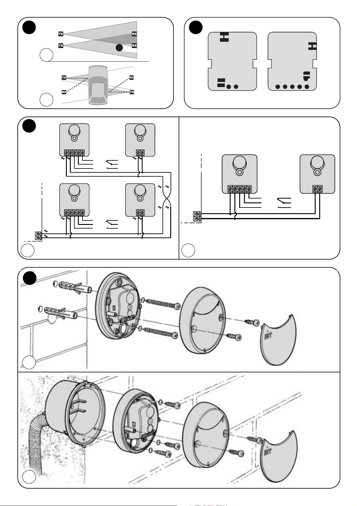
Installation The TX transmitter of the
photocell emits a beam at an angle of about 20°.
If two devices are near to one another, the beam may
interfere with the other receiver (figure 1a) and not
provide a sufficient level of safety.
In order to solve this problem and if alternating current
is available, the synchronisation system that allows the
two pairs of photocells to work alternately may be used.
This system requires the synchronism jumper “SINC”
to be cut on the two TX’s (fig. 2) and the 1
st
pair of
photocells (TX and RX) to be powered with their
phases inverted compared with the 2
nd
pair. (fig. 3).
Before proceeding with installation, check the
following points:
-If the photocells are powered with 12V, place a tin
jumper between the two “12V” points both on TX and
RX (see fig. 2).
-If the distance between TX and RX is greater than 10
metres, cut the jumper between the “+10m” points of
RX (see fig. 2).
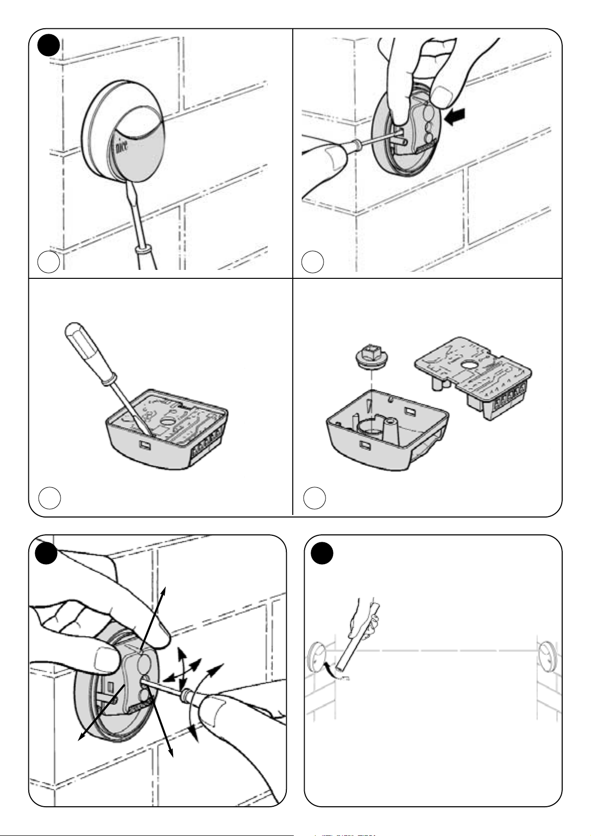
-If the effective opening angle is required to be
reduced to ±5°, fit the reducer cone as shown in fig.
5a, 5b, 5c, 5d.
-Given that the direction of the “MOF” fixed photocell
cannot be adjusted, when using this version make
sure that the surfaces to which TX and RX are fixed
allow them to be perfectly aligned.
Fix the photocells as shown in figure 4a or 4b.
Make the relative electrical connections as shown in
the control panel manuals and in fig. 3.
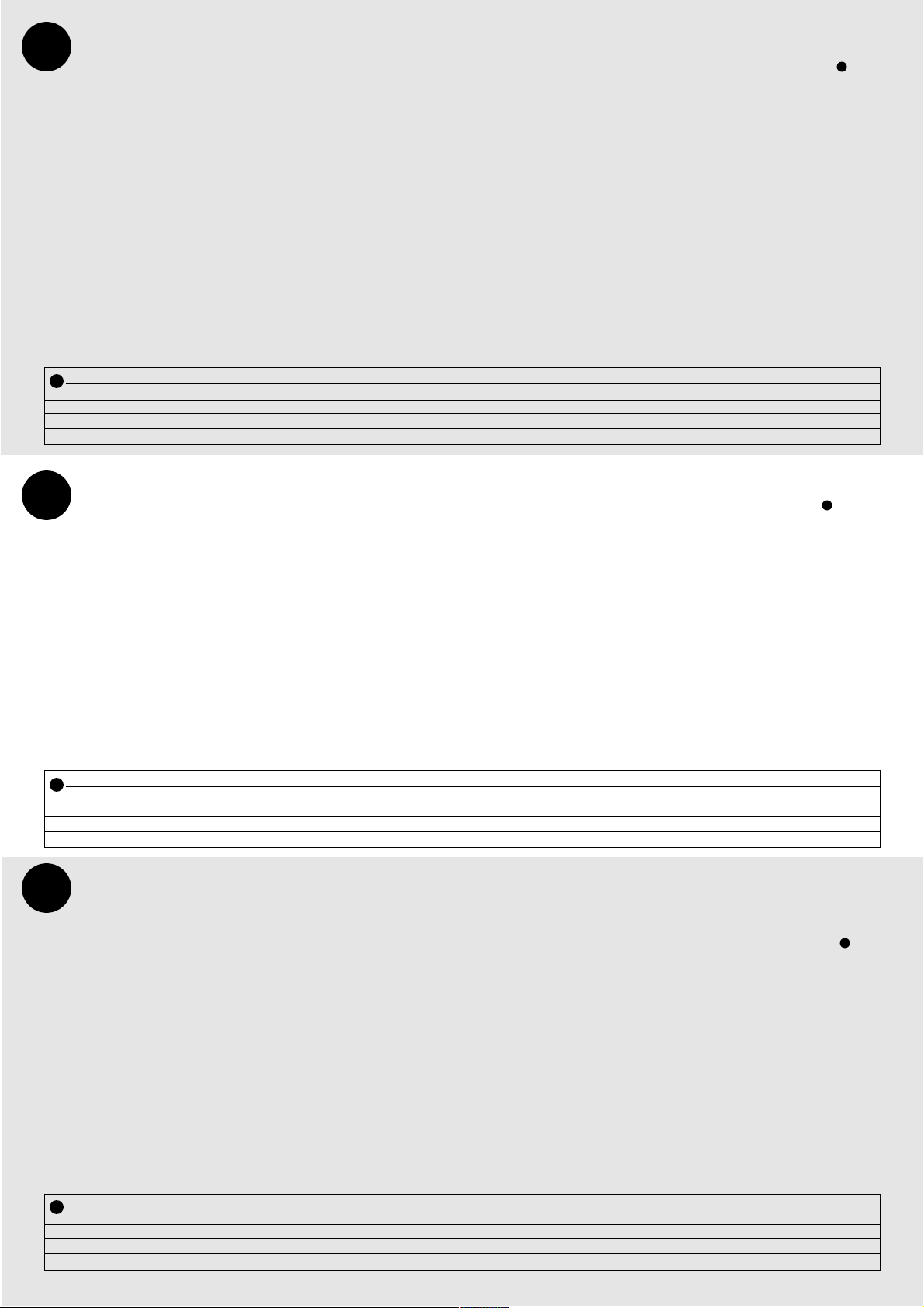
Adjusting direction The direction of the
“MOFO” mobile photocell can be adjusted to achieve
a perfect alignment even when the fixing position is not
perfect. Adjustment must be particularly precise when
the cone for reducing the effective opening angle to
±5° is used.
Proceed as shown in figure 6 to adjust the direction.
Loosen screw “A”, gently move the mobile element B
and then tighten screw “A”.
If the reducing cone is not used on the transmitter and
receiver, adjustment can be made less precisely.
If the reducing cone is used on the receiver,
adjustment must be extremely precise, follow the
indicator “L”: the slower it flashes, the better the
alignment is. Alignment is perfect when “L” stays off
but is acceptable when “L” flashes slowly; it is
incorrect when “L” flashes quickly. Afterwards, check
the result using the following table .
Testing The whole installation on which the safety
device is installed must be tested by trained and
qualified personnel who must carry out the relative
tests according to the elements of risk present. The
device must be tested using the following procedure:
-Disconnect the photocell from the power supply and
check the ALARM state
-Power the receiver and check the ALARM state
-Then power the transmitter as well and check the
ALARM state
-Use a 5 cm diameter and 20 cm long cylinder to
interrupt the beam, first near the TX’s, then near the
RX’s and lastly in the centre and check that the safety
device cuts in and modifies the state of the outputs
from ACTIVE to ALARM and vice-versa. (figure 7)
Installation L’émetteur TX de la photocellule
émet un rayon ayant un angle d’environ 20°.
Dans le cas de deux dispositifs proches l’un de
l’autre, le rayon pourrait interférer sur l’autre récepteur (figure 1a) en compromettant ainsi la sécurité.
Pour remédier à ce problème, si l’alimentation au
courant alternatif est disponible, il est possible
d’utiliser le système de synchronisme qui permet de
faire fonctionner alternativement les deux paires de
photocellules.
Ce système prévoit que le shunt de synchronisme
“SINC” soit coupé sur les deux TX (voir figure 2) et que
la 1
re
paire de photocellules (TX et RX) soit alimentée
avec les phases inversées par rapport à la 2epaire. (fig. 3).
Avant de procéder dans l’installation, il est bon de
vérifier les points suivants:
- Si les photocellules sont alimentées à 12V il faut
effectuer un shunt à l’étain entre les deux points “12V”
aussi bien sur TX que sur RX (fig. 2).
- Si la distance entre TX et RX est supérieure à 10 m,
éliminer le shunt entre les points “+10m.” du RX (fig. 2).
- S’il faut réduire l’angle d’ouverture effectif à ±5°, insérer
le cône de réduction comme sur la fig. 5a, 5b, 5c, 5d.
- Quand on utilise la photocellule MOF, le réglage de
l’orientation n’étant pas disponible, il faut contrôler que
la surface de fixation permet d’effectuer correctement
le centrage TX-RX
Fixer les photocellules comme l’indique la figure 4a -4b.
Effectuer les connexions électriques suivant la fonction
désirée, conformément aux indications figurant dans le
manuel des coffrets de commande et celles de la fig. 3
Réglage de l’orientation La photocellule
MOFO dispose du réglage de l’orientation qui permet
d’obtenir un alignement parfait même quand la fixation
n’est pas optimale. L’orientation doit être
particulièrement précise quand on insère le cône pour
la réduction de l’angle d’ouverture effectif à ±5°.
Pour régler l’orientation, procéder comme l’indique la
figure 6. Desserrer légèrement la vis “A” faire osciller
lentement la partie mobile B, puis serrer la vis “A”. Sur
l’émetteur et sur le récepteur sans cône de réduction,
le réglage peut être effectué de manière
approximative. Sur le récepteur avec cône de
réduction, le réglage doit être très précis, suivre le
signal donné par l’indicateur “L”: plus le clignotement
est lent et plus le centrage est précis.
Le centrage idéal s’obtient quand “L” reste éteint, il est
toutefois acceptable quand “L” clignote lentement; il
est par contre à risque quand “L” clignote rapidement.
À la fin de l’opération, vérifier le résultat à l’aide du
tableau ci-après .
Essai L’essai de l’installation dans laquelle est
monté le dispositif de sécurité doit être effectué par du
personnel expérimenté et qualifié qui devra se charger
des essais requis en fonction du risque présent.
L’essai du dispositif proprement dit devra être effectué
à l’aide de la procédure suivante:
- Couper l’alimentation des photocellules et vérifier
l’état d’ALARME
- Alimenter seulement le récepteur et vérifier l’état
d’ALARME
- Alimenter aussi l’émetteur et vérifier l’état d’ACTIF
- Passer avec un cylindre de 5 cm de diamètre et de
20 cm de longueur sur l’axe optique d’abord près des
TX puis près des RX et enfin au centre du passage et
vérifier que dans tous les cas, le dispositif intervient en
modifiant l’état des sorties d’ACTIF à ALARME et vice
versa. (figure 7)
GB
F
Installazione Il trasmettitore TX della
fotocellula emette un raggio con un angolo di
circa 20°. Nel caso di due dispositivi vicini, il
raggio potrebbe interferire sull’altro ricevitore
(fig.1a) non garantendo un’adeguata sicurezza.
Per ovviare a questo problema, se disponibile
l’alimentazione in corrente alternata, è possibile
utilizzare il sistema di sincronismo che permette di far
funzionare alternativamente le due copie di fotocellule.
Questo sistema prevede che venga tagliato il
ponticello di sincronismo “SINC” sui due TX ( vedi
figura 2) e che la 1
a
coppia di fotocellule (TX e RX) sia
alimenta con le fasi invertite rispetto alla 2
a
coppia.
(vedi fig 3).
Prima di procedere con l’installazione è opportuno
verificare i seguenti punti:
-Se si alimentano le fotocellule con una tensione di
12V è necessario effettuare un ponticello di stagno tra
i due punti “12V” sia su TX che su RX (vedi fig.2).
-Nel caso la distanza tra TX ed RX sia superiore a 10
metri tagliare il ponticello tra i punti “+10m.”del RX
(vedi fig.2).
-Se richiesta la riduzione dell’effettivo angolo di aper-
tura a ±5° inserire sul ricevitore il cono di riduzione
come in fig. 5a, 5b, 5c, 5d
-Quando si utilizza la fotocellula fissa MOF non
essendo disponibile la regolazione dell’orientamento
occorre accertarsi che la superfici di fissaggio
permettano una corretta centratura TX-RX
Effettuare il fissaggio delle fotocellule come indicato in
fig. 4a o 4b.
Eseguire i collegamenti elettrici in base alla funzione
richiesta, secondo quanto riportato nei manuali dei
quadri di comando e seguendo le indicazioni in fig.3.
Regolazione dell’orientamento
Nella fotocellula orientabile MOFO è disponibile la
regolazione dell’orientamento che consente di ottenere
un perfetto allineamento anche quando il fissaggio non è
ottimale. L’orientamento deve essere particolarmente
preciso quando viene inserito il cono per la riduzione
dell’effettivo angolo di apertura a ±5°.
Per regolare l’orientamento procedere come indicato in
figura 6. Allentare leggermente la vite “A” far oscillare
lentamente la parte mobile B, infine richiudere la vite “A”.
Nel trasmettitore, e nel ricevitore senza cono di riduzione,
la regolazione può essere fatta in modo approssimativo.
Nel ricevitore con cono di riduzione la regolazione deve
essere molto precisa, seguire la segnalazione
dell’indicatore “L”: minore è la velocità del lampeggio e
migliore è la centratura. La centratura ottimale si ha
quando “L” rimane spento, comunque accettabile
quando “L” lampeggia lentamente, a rischio invece
quando “L” lampeggia velocemente. Al termine verificare
il risultato tramite la seguente tabella .
Collaudo Il collaudo dell’intero impianto in cui è
inserito il dispositivo di sicurezza dovrà essere
eseguito da personale esperto e qualificato che dovrà
farsi carico delle prove richieste in funzione del rischio
presente.
Il collaudo del singolo dispositivo dovrà essere
eseguito con questa semplice procedura:
-Togliere l’alimentazione alle fotocellule e verificare lo
stato di ALLARME
-Alimentare il solo ricevitore, verificare lo stato di ALLARME
-Alimentare anche il trasmettitore e verificare lo stato di
ATTIVO
- Passare con un cilindro di diametro 5 cm e lunghezza
20 cm sull’asse ottico prima vicino ai TX, poi vicino agli
RX e infine al centro del varco e verificare che in tutti i
casi il dispositivo intervenga modificando lo stato delle
uscite da ATTIVO ad ALLARME e viceversa. (vedi fig.7)
I
Y
Indicatore L
Sempre spento
Lampeggio lento
Lampeggio veloce
Sempre acceso
Significato
Segnale OK = Nessun ostacolo
Segnale scarso = Nessun ostacolo
Segnale pessimo = Nessun ostacolo
Segnale zero = Presente ostacolo
Stato uscita
Attivo
Attivo
Attivo
Allarme
Azione
Tutto Ok
Migliorare centratura
Verificare centratura, stato pulizia e ambiente
Rimuovere ostacolo
Y
Indicateur L
Toujours éteint
Clignotement lent
Clignotement rapide
Toujours allumé
Signification
Signal OK Aucun obstacle
Signal insuffisant Aucun obstacle
Mauvais signal Aucun obstacle
Signal zéro Présence d’obstacle
État sortie
Actif
Actif
Actif
Alarme
Action
OK
Améliorer le centrage
Vérifier le centrage la propreté et l’environnement
Éliminer l’obstacle
Y
Y
Y
Y
Page 7
Instalación El transmisor TX de la fotocélula
emite un rayo con un ángulo de alrededor de 20°.
Si hay dos dispositivos cercanos, el rayo podría
interferir sobre el otro receptor (figura 1a) no
garantizando una seguridad adecuada.
Para obviar dicho problema, si está disponible la
alimentación con corriente alterna, se puede utilizar el
sistema de sincronismo y así hacer funcionar
alternativamente los dos pares de fotocélulas.
Este sistema prevé que se corte la conexión puente de
sincronismo “SINC” en los dos TX (véase figura 2) y que
el 1° par de fotocélulas (TX y RX) sea alimentado con las
fases invertidas con respecto al 2° par. (véase fig.3).
Antes de proceder con la instalación es oportuno
verifique los siguientes puntos:
- Si se alimentan las fotocélulas con una tensión de 12V
hay que hacer una conexión puente de estaño entre los
dos puntos “12V” tanto en TX como en RX (fig. 2).
- Si la distancia entre TX y RX supera los 10 metros,
corte la conexión puente entre los puntos “+10m.” del
RX (fig. 2).
- Si se requiere reducir el ángulo efectivo de apertura a
±5° monte el cono de reducción, como muestra la fig. 5a,
5b, 5c, 5d
- cuando se utiliza MOF, puesto que no se dispone de la
regulación de la orientación, compruebe que la superficie
de fijación permita un centrado correcto TX-RX
Fije las fotocélulas como indicado en la figura 4a - 4b
Realice las conexiones eléctricas según la función
requerida, de acuerdo con las indicaciones de los
manuales de los cuadros de mando y siguiendo las
indicaciones de la fig. 3
Regulación de la orientacion En MOFO se
dispone de la regulación de la orientación, que permite
obtener una alineación perfecta cuando la fijación no es
ideal. La orientación debe ser muy precisa cuando se
monta el cono para la reducción del ángulo efectivo de
apertura a ±5°.
Para regular la orientación, proceda con las
indicaciones de la figura 6. Afloje ligeramente el tornillo
“A” para hacer oscilar lentamente la parte móvil B, luego
apriete el tornillo “A”.En el transmisor y en el receptor sin
cono de reducción, la regulación será aproximada.
En el receptor con cono de reducción, la regulación debe
ser muy precisa, siga la señal del indicador “L”: menor es
la velocidad de parpadeo y mejor es el centrado. El
centrado ideal se obtiene cuando “L” queda apagado; sin
embargo, es aceptable cuando “L” parpadea
lentamente, no así cuando "L" parpadea velozmente. Al
final, controle el resultado siguiendo la tabla .
Ensayo El ensayo de toda la instalación en donde
está montado el dispositivo de seguridad deberá ser
llevado a cabo por personal experto y calificado, que
será responsable de las pruebas requeridas según el
riesgo presente.
El ensayo de cada dispositivo se deberá hacer con este
simple procedimiento:
- Corte la alimentación a la fotocélula y compruebe el
estado de ALARMA
- Alimente sólo el receptor y compruebe el estado de
ALARMA
- Alimente también el transmisor y compruebe el estado
de ACTIVO
- Pase un cilindro de 5 cm de diámetro y 20 cm de largo
sobre el eje óptico, primero cerca de los TX, luego cerca
de los RX y por último en el centro del paso y
compruebe que en todos los casos el dispositivo se
accione modificando el estado de las salidas de
ACTIVO a ALARMA y viceversa. (figura 7)
Einbau Der Sender TX der Photozelle gibt einen
Strahl mit einem Winkel von ca. 20° ab . Wenn sich
zwei Vorrichtungen nahe aneinander befinden,
könnte sich der Strahl mit dem anderen Empfänger
überschneiden (Abbildung 1a), wodurch keine passende
Sicherheit gewährleistet würde.
Um diesem Problem aus dem Weg zu gehen, wenn die
Wechselstromvorsorgung vorhanden ist, kann das
Gleichlaufsystem benützt werden, mit dem zwei
Photozellenpaare abwechselnd betrieben werden.
Bei diesem System muss die Gleichlaufbrücke “SINC” an
den zwei TX durchgeschnitten werden (siehe Abbildung 2)
und das 1. Photozellenpaar (TX und RX) muss mit
umgekehrten Phasen im Vergleich zum 2. Paar gespeist
werden (siehe Abb. 3).
Vor dem Einbau sollten folgende Punkte überprüft werden:
- Falls die Photozellen mit 12V Spannung gespeist werden,
muss sowohl an TX als auch an RX eine Brücke zwischen
die zwei “12V” Punkte gelötet werden (siehe Abb.2).
- Sollte der Abstand zwischen TX und RX größer als 10
Meter sein, die Brücke zwischen den “+10m.”-Punkten
des RX durchschneiden (siehe Abb. 2).
- Falls die Reduzierung des effektiven Öffnungswinkels
auf ±5°erforderlich ist, den Reduzierkegel wie in Abb. 5a,
5b, 5c, 5d gezeigt einfügen.
- Wenn MOF benützt wird und da die Orientierung nicht
reguliert werden kann, muss sichergestellt werden, dass
die Befestigungsflächen eine korrekte Zentrierung von TX
und TX ermöglichen. Die Photozellen gemäß den
Angaben in Abb. 4a - 4b befestigen.
Die elektrischen Anschlüsse je nach verlangten
Funktionen, nach den Angaben in den Anleitungen der
Schalttafeln und den Anweisungen in Abb. 3 ausführen.
Regulieren den Orienterung In der MOFO
kann die Orientierung reguliert werden, so dass auch bei
nicht optimaler Befestigung eine perfekte Fluchtung
erzielt wird. Die Orientierung muss besonders präzis sein,
wenn der Kegel für die Reduzierung des effektiven
Öffnungswinkels auf ±5° eingefügt wird.
Zum Regulieren der Orientierung ist wie in Abb. 6 gezeigt
vorzugehen. Die Schraube “A” etwas lockern, den
beweglichen Teil B langsam schwingen lassen, dann die
Schraube “A” wieder anziehen.
Am Sender und am Empfänger ohne Reduzierkegel kann
das Regulieren auf annähernde Weise erfolgen.
Am Empfänger mit Reduzierkegel muss sehr präzis
reguliert werden; den Anzeiger “L” beachten: je
langsamer er blinkt, desto besser ist die Zentrierung.
Optimal zentriert ist, wenn “L” gar nicht blinkt, es ist
jedoch akzeptierbar, wenn “L” langsam blinkt, ein
Schnellblinken von “L” ist mit Risiken verbunden. Am
Ende das Ergebnis nach der folgenden Tabelle .
Prüfung Die ganze Anlage, in welche die
Sicherheitsvorrichtung eingeschaltet wird, muss von
erfahrenem Fachpersonal geprüft werden, das die
erforderlichen Tests in Abhängigkeit vom vorhandenen
Risiko ausführen muss.
Die Prüfung der einzelnen Vorrichtung muss nach diesem
einfachen Verfahren erfolgen:
- Die Speisung zu den Photozellen abschalten und den
ALARM-Zustand überprüfen
- Nur den Empfänger speisen und den ALARM-Zustand
überprüfen
- Auch den Sender speisen und den AKTIV-Zustand
überprüfen
- Einen Zylinder mit 5 cm Durchmesser und 20 cm Länge
auf der optischen Achse zuerst in der Nähe der TX, dann
in der Nähe der RX und am Ende in ihrer Mitte
durchführen und prüfen, dass die Vorrichtung in allen
Fällen anspricht, indem sich der Zustand der Ausgänge
von AKTIV auf ALARM und umgekehrt ändert.
(siehe Abb.7)
Wskaźnik L
Zawsze wyłączony
Światło przerywane wolne
Światło przerywane szybkie
Zawsze włączony
Znaczenie
Sygnał OK Nie ma przeszkody
Sygnał słaby Nie ma przeszkody
Sygnał gorszy Nie ma przeszkody
Sygnał zero Jest przeszkoda
Stan wyjścia
Aktywny
Aktywny
Aktywny
Alarm
Czynność do wykonania
Wszystko Ok
Poprawić ustawienie w linii
Sprawdzić ustawienie w linii Stan czystości i środowisko
Usunąć przeszkodę
Instalowanie
Nadajnik TX fotokomórki wydaje promień z kątem
około 20˚. Gdy dwa urządzenia znajdują się blisko
siebie, wówczas promień może przeszkodzić
drugiemu odbiornikowi (rysunek 1a) nie gwarantując
właściwego zabezpieczenia.
W celu uniknięcia tego problemu gdy mamy do dyspozycji
zasilanie prądem zmiennym można zastosować system
synchronizujący, który pozwoli na pracę dwóch
fotokomórek w systemie zmiennym.
Zgodnie z tym systemem zostanie przecięty mostek
synchronizujący “SINC” na dwóch TX (patrz rysunek 2) i 1
a
para fotokomórek (TX i RX) będzie zasilana fazami w
kierunku odwróconym w stosunku do 2
a
pary (patrz
rysunek 3).
Przed czynnościami instalowania należy sprawdzić
następujące punkty:
- Gdy fotokomórki zasilane są napięciem 12V należy
wykonać mostek pomiędzy dwoma punktami “12V”, na TX
jak i na RX (patrz rysunek 2).
- W przypadku gdy odległość pomiędzy TX i RX jest
większa niż 10 metrów należy przeciąć mostek pomiędzy
punktami “+10m.” w RX (patrz rysunek 2).
- Gdy zażądana zostanie redukcja efektywnego kąta
otwarcia o +/-5˚ należy wsadzić stożek redukcyjny do
odbiornika tak jak pokazano na rysunku 5a, 5b, 5c, 5d.
- Gdy używa się fotokomórkę stalą “MOF” przy braku
możliwości regulacji kierunku należy sprawdzić czy
powierzchnie sużące do ich przymocowania pozwalają na
właściwe ustawienie w linii TX-RX
Przymocować fotokomórki tak jak zostało wskazane na
rysunku 4a - 4b
Należy wykonać podłączenia elektryczne według żądanej
funkcji, według wskazówek umieszczonych na tablicach
sterowniczych i według rysunku 3.
Regulacja kierunku
Na komórce ruchomej “MOFO” możliwa jest regulacja
kierunku, która pozwala na perfekcyjne ustawienie w linii
nawet wtedy, gdy powierzchnia mocująca nie jest
optymalna. Wówczas gdy założony jest stożek do redukcji
efektywnego kąta otwarcia +/5˚ należy dokładnie ustawić
kierunek.
Przy regulacji kierunku należy postąpić tak jak
przedstawiono na rysunku 6. Zwolnić lekko śrubę “A” tak
aby lekko przesunąć część ruchomą B, po czym dokręcić
śrubę “A”.
W nadajniku i w odbiorniku bez stożka redukcyjnego
regulacje wykonuje się w sposób podobny.
W odbiorniku ze stożkiem redukcyjnym regulacja ma być
wykonana bardzo dokładnie, należy kierować się
wskażnikiem “L”: im mniejsza prędkość przerywania światła
tym lepsze jest ustawienie w linii.
Najlepsze ustawienie w linii jest wtedy, gdy “L” nie świeci
się, do zaakceptowania gdy “L” świeci się z wolnym
przerywaniem, a jest ryzykowne wtedy, gdy przerywanie
światła “L” jest szybkie. Po zakończeniu regulacji należy
sprawdzić wynik porównując z poniższą tabelką .
Próby odbiorcze
Próby odbiorcze całego urządzenia z urządzeniem
bezpieczeństwa mają być wykonywane przez osobę z
odpowiednimi kwalifikacjami, która będzie odpowiadać za
wykonane próby jak i za bezpieczeństwo podczas ich
wykonywania. Próby odbiorcze pojedynczego urządzenia
mają być wykonywane według poniższej kolejności:
- Odciąć zasilanie fotokomórek i sprawdzić stan ALARMU
- Podłączyć zasilanie do odbiornika i sprawdzić stan
ALARMU
- Podłączyć zasilanie do nadajnika i sprawdzić
AKTYWNOŚCI
- Cylindrem o średnicy 5 cm i długość 20 przesunąć po
osi optycznej najpierw w pobliżu TX, a następnie w pobliżu
RX i po środku przejścia i sprawdzić czy w każdym
przypadku urządzenie zainterweniuje zmieniając stan
wyjściowy z AKTYWNEGO na ALARMOWY i na odwrót.
(rysunek 7)
D
E
PL
Anzeiger L
Immer aus
Langsam- blinken
Schnell-blinken
Immer ein
Bedeutung
Signal OK Kein Hindernis
Wenig Signal Kein Hindernis
Sehr schlechtes Signal Kein Hindernis
Kein Signal Hindernis vorhanden
Ausgangszustand
Aktiv
Aktiv
Aktiv
Alarm
Aktion
Alles Ok
Besser zentrieren
Zentrierung, Sauberkeit und Umgebung überprüfen
Hindernis entfernen
Y
Indicador L
Siempre apagado
Parpadeo lento
Parpadeo veloz
Siempre encendido
Significado
Señal OK Ningún obstáculo
Señal escasa Ningún obstáculo
Señal pésima Ningún obstáculo
Señal cero Presente obstáculo
Estado salida
Activo
Activo
Activo
Alarma
Acción
Todo Ok
Mejorar el centrado
Comprobar el centrado limpieza y entorno
Quitar el obstáculo
Y
Y
Y
Y
Y
Page 8

(secondo Direttiva 98/37/EC, Allegato II, parte C) (according to 98/37/EC Directive, Enclosure II, part C)
Numero / Number: 113/MOF Data / Date: 07/2000 Revisione / Revision: Ø
Il sottoscritto Lauro Buoro, Amministratore Delegato, dichiara che il prodotto
The undersigned Lauro Buoro, General Manager of the following producer, declares that the product
Nome produttore / Producer name: NICE S.p.A.
Indirizzo / Address: Via Pezza Alta 13, 31046 Z.I. Rustignè – ODERZO - ITALY
Tipo / Type: Fotocellula serie “MOON” / Photocells series “MOON”
Modello / Model: MOF, MOFO
Accessori / Accessories: Nessun accessorio / No accessory
Risulta conforme a quanto previsto dalle seguenti direttive comunitarie / Appears to be in conformity with the following community (EEC) regulations
Riferimento n° Titolo
Reference n° Title
98/37/EC (EX 89/392/CEE) DIRETTIVA MACCHINE / Machinary Directive
89/336/CEE DIRETTIVA COMPATIBILITA’ ELETTROMAGNETICA (EMC) / EMC Electromagnetic Compatibility Directive
73/23/CEE - 93/68/CEE DIRETTIVA BASSA TENSIONE e successiva modifica / Low Voltage Directive
e che sono state applicate le specifiche tecniche di prodotto sotto-indicate.
and that the product technical specifications referenced overleaf have been applied.
Inoltre dichiara che non è consentita la messa in servizio del prodotto suindicato finché la macchina, in cui il prodotto stesso è
incorporato, non sia identificata e dichiarata conforme alla direttiva 89/392/CEE
He declares, moreover, that it is not allowed to use the above mentioned product until the machine, in which this product is incorporated, has been identified
and declared in conformity with the regulation 89/392/CEE.
Riferimento relativo alle norme e specifiche tecniche, o parti di esse, utilizzate per la presente dichiarazione di conformità:
Reference about to the regulations of the technical specifications, or parts of them, applied for this declaration of conformity:
Norme armonizzate / Harmonized standards
Riferimento n° Edizione Titolo Livello di valutazione Classe
Reference n° Issue Title Estimate level Class
EN61000-4-3 11/1997 SUSCETTIBILITA’ RADIATA / Radiated susceptibility 10V/m A
ENV50204 SUSC. RADIATA MODULAZIONI A IMPULSI 10V/m A
EN61000-4-6 11/1997 SUSCETTIBILITA’ CONDOTTA / Radiated and Conducted Susceptibility 10V A
EN61000-4-4 09/1996 IMMUNITA’ AI BURST / Fast Transient 2000V B
EN61000-4-2 09/1996 IMM. ALLE SCARICHE ELETTR. (EDS) / Electrostatic Discharge 6KV, 8KV B
EN61000-4-11 09/1996 IMM. AI BUCHI DI TENSIONE / Power Fail B - C
EN61000-4-8 06/1997 IMMUNITA’ AL CAMPO MAGNETICO A FREQUENZA DI RETE B
Power – frequency Magnetic fields
EN61000-4-5 06/1997 IMMUNITA’ AI SURGE / Surge Immunity 2 KV B
EN61496-1 10/1998 SICUREZZA DEL MACCHINARIO-APPARECCHI ELETTROSENSIBILI
DI PROTEZIONE – PARTE 1: PRESCRIZIONI GENERALI E PROVE
Safety of machinary - Electro-sensitive protective
equipment - Part 1: General requirementes and tests
IEC61496-2 11-1997 SAFETY OF MACHINARY - ELECTRO-SENSITIVE
EQUIPMENT - PART 2: PARTICOLAR REQUIREMENTS
FOR EQUIPMENT USING ACTIVE OPTO - ELECTRONIC
PROTECTIVE DEVICES (AOPDs)
Altre norme e/o specifiche tecniche di prodotto / Other standards and/or product technical specifications
Riferimento n° Edizione Titolo Livello di valutazione
Reference n° Issue Title Estimate level
UNI 8612 06/1989 CANCELLI E PORTONI AUTOMATICI.
CRITERI COSTRUTTIVI E DISPOSITIVI DI PROTEZIONE
Motorized gates and main doors - Protection devices against accidents
EN 954-1 12/1998 PARTI DEI SISTEMI DI COMANDO LEGATE ALLA SICUREZZA 1
Safety - related parts of control systems
NFP25-363 08/1994 PORTES ET PORTAILS COMPLETS
COMPOSANTS DE SECURITE’ - METHODES D’ESSAIS
Shutters for open bays and gates - Outfitted doors
and gates - Safety components - Test methods
prEN12978 10/1998 DISPOSITIVI DI SICUREZZA REQUISITI E METODI DI PROVA
Safety devices - Requirement and test methods
P. S . : Il prodotto montato con le nostre centrali dotate della funzione “fototest”, permette di ottenere un livello di sicurezza di categoria 2.
The product allows to have an safety level 2, if is installed to control unit with fototest
Il prodotto suindicato si intende parte integrante di una delle configurazioni di installazione tipiche, come riportato nei nostri cataloghi generali
The above mentioned product is meant integral part of one of the installation configuration as shown on our general catalogues
Oderzo, lì 17 Luglio 2000 (Amministratore Delegato / General Manager)
Lauro Buoro
Dichiarazione CE di conformità / EC declaration of conformity
ISTFM 4854 REV. 01
Nice SpA, Oderzo TV Italia
Via Pezza Alta, 13 Z. I. Rustignè
Tel. +39.0422.85.38.38
Fax +39.0422.85.35.85
E-mail info@niceforyou.com
Web site http://www.niceforyou.com
Nice France, Buchelay
Tel. +33.(0)1.30.33.95.95
Fax +33 (0)1.30.33.95.96
Nice Polska, Pruszków
Tel. +48.22.728.33.22
Fax +48.22.728.25.10
 Loading...