


NEXCOM International Co., Ltd.
Intelligent Digital Security
IP Camera
NCr-302-VHR
User Manual
NEXCOM International Co., Ltd.
Published January 2015
www.nexcom.com

Content
Contents
Preface
Copyright .............................................................................................. v
Disclaimer ............................................................................................... v
Acknowledgements ................................................................................ v
Regulatory Compliance Statements ......................................................... v
Declaration of Conformity ....................................................................... v
RoHS Compliance .................................................................................. vi
Safety Information .................................................................................vii
Installation Recommendations ................................................................vii
Safety Precautions .................................................................................viii
Technical Support and Assistance ........................................................... ix
Conventions Used in this Manual ........................................................... ix
Package Contents ................................................................................... x
Chapter 1: Product Introduction
Overview ................................................................................................1
Key Features ...........................................................................................1
Hardware Specifications ..........................................................................2
DI/O & Function Description .................................................................... 4
DI/O Pin Definition & Waterproof Connector Description .........................4
Cable Wiring Description ........................................................................5
Cable Outlet Description ......................................................................... 6
Hardware Installation ..............................................................................6
Chapter 2: Camera Configuration
Accessing the Camera’s Configuration Menu (Graphical User Interface) ..8
Installing IP-FINDER ..........................................................................8
IP-FINDER ....................................................................................... 11
Web Browser (Internet Explorer) .....................................................13
Configuring the Camera’s Setting .........................................................14
Browsing Through the Configuration Menu .......................................15
Video .................................................................................................... 16
Video Stream .....................................................................................16
Stream 1 ........................................................................................16
Stream 2 ........................................................................................17
Stream 3 ........................................................................................17
Camera Settings ................................................................................ 18
Image Adjustments ........................................................................18
Mirror & Flip ...................................................................................19
Wide Dynamic Range (WDR) .......................................................... 19
Camera Settings Cont. ......................................................................20
White Balance ................................................................................ 20
Exposure ........................................................................................20
Day & Night ...................................................................................21
Overlay Settings .................................................................................22
Contents ........................................................................................ 22
Privacy Mask ......................................................................................23
Settings ..........................................................................................23
Mask Zones ....................................................................................24
Network ...............................................................................................25
TCP/IP ................................................................................................25
IP Address Configuration ................................................................25
Current Network Settings ...............................................................25
FTP .................................................................................................... 26
FTP Server ......................................................................................26
Copyright © 2013 NEXCOM International Co., Ltd. All Rights Reserved.
ii
NCr-302-VHR User Manual

Content
Login Information ..........................................................................26
Test Remote FTP Server ...................................................................26
SMTP .................................................................................................27
SMTP Server ................................................................................... 27
Login Information ..........................................................................27
To Mail Address ..............................................................................27
Ports ..................................................................................................28
HTTP .............................................................................................. 28
RTSP ..............................................................................................28
Events ................................................................................................... 29
Motion Detection ..............................................................................29
Settings ..........................................................................................29
Detection Zones ............................................................................. 30
Alarm In/Out Trigger .......................................................................... 31
Alarm In Control ............................................................................31
Alarm Out Control ........................................................................... 31
Event Actions ....................................................................................32
When Motion Detection Triggered .................................................32
When Alarm In Triggered ...............................................................32
System .................................................................................................. 34
Audio ................................................................................................ 34
Audio Settings ...............................................................................34
Recording Settings .............................................................................35
AVI File Setting ...............................................................................35
User Management ............................................................................. 36
Add/Modify User Accounts .............................................................36
User List ......................................................................................... 36
SD Card Management .......................................................................37
SD Card Information ......................................................................37
File List ........................................................................................... 37
Date & Time ...................................................................................... 38
Current Camera Time .....................................................................38
Time Settings ................................................................................. 38
Date & Time Format ....................................................................... 39
NTP Server .....................................................................................39
Firmware Upgrade .............................................................................40
Firmware Version ...........................................................................40
Update ...........................................................................................40
Maintenance .....................................................................................41
Maintain ........................................................................................41
Camera Name Settings ................................................................... 41
Advanced Settings ................................................................................42
Video .................................................................................................... 43
Camera Settings (Advanced) .............................................................. 43
Chroma & Sharpness Suppression ..................................................43
Manual White Balance ...................................................................43
Manual Exposure & Gain ................................................................43
Camera Settings (Advanced) Cont. ....................................................44
Auto Exposure Configuration .........................................................44
P-Iris Control ..................................................................................44
IR Cut Filter (ICR) Control ...............................................................44
IR LED Control ................................................................................45
Gamma Control .............................................................................45
ROI .................................................................................................... 46
Auto Exposure Weights .....................................................................47
Network ...............................................................................................48
DDNS ................................................................................................48
DDNS Settings ................................................................................48
SNMP ................................................................................................ 49
SNMP v1/v2 ...................................................................................49
Traps for SNMP v1/v2 ..................................................................... 49
SNMP v3 ........................................................................................ 49
Multicast ...........................................................................................50
Settings ..........................................................................................50
Copyright © 2013 NEXCOM International Co., Ltd. All Rights Reserved.
iii
NCr-302-VHR User Manual

Content
Events ................................................................................................... 51
Ethernet Lost Detection ..................................................................... 51
Settings ..........................................................................................51
Face Detection ...................................................................................52
Tampering Detection .........................................................................53
Settings ..........................................................................................53
Event Actions (Advanced) ..................................................................54
When Motion Detection Triggered .................................................54
When Tampering Detection Triggered ............................................. 54
System .................................................................................................. 55
Schedule Recording ...........................................................................55
Schedule Recording Setting ............................................................55
Chapter 3:
Viewing Live Video via VLC Media Player.............56
Copyright © 2013 NEXCOM International Co., Ltd. All Rights Reserved.
iv
NCr-302-VHR User Manual

Preface
PrefaCe
Copyright
This publication, including all photographs, illustrations and software, is
protected under international copyright laws, with all rights reserved. No
part of this manual may be reproduced, copied, translated or transmitted in
any form or by any means without the prior written consent from NEXCOM
International Co., Ltd.
Disclaimer
The information in this document is subject to change without prior notice and
does not represent commitment from NEXCOM International Co., Ltd. However,
users may update their knowledge of any product in use by constantly checking
its manual posted on our website: http://www.nexcom.com. NEXCOM shall
not be liable for direct, indirect, special, incidental, or consequential damages
arising out of the use of any product, nor for any infringements upon the rights
of third parties, which may result from such use. Any implied warranties of
merchantability or fitness for any particular purpose is also disclaimed.
Acknowledgements
NCr-302-VHR is a trademark of NEXCOM International Co., Ltd. All other
product names mentioned herein are registered trademarks of their
respective owners.
Regulatory Compliance Statements
This section provides the FCC compliance statement for Class B devices and
describes how to keep the system CE compliant.
Declaration of Conformity
FCC
This equipment has been tested and verified to comply with the limits for
a Class B digital device, pursuant to Part 15 of FCC Rules. These limits are
designed to provide reasonable protection against harmful interference when
the equipment is operated in a commercial environment. This equipment
generates, uses, and can radiate radio frequency energy and, if not installed
and used in accordance with the instructions, may cause harmful interference
to radio communications. Operation of this equipment in a residential area
(domestic environment) is likely to cause harmful interference, in which
case the user will be required to correct the interference (take adequate
measures) at their own expense.
CE
The product(s) described in this manual complies with all applicable
European Union (CE) directives if it has a CE marking. For computer systems
to remain CE compliant, only CE-compliant parts may be used. Maintaining
CE compliance also requires proper cable and cabling techniques.
Copyright © 2013 NEXCOM International Co., Ltd. All Rights Reserved.
v
NCr-302-VHR User Manual

Preface
RoHS Compliance
NEXCOM RoHS Environmental Policy and Status
Update
NEXCOM is a global citizen for building the digital
infrastructure. We are committed to providing green
products and services, which are compliant with
European Union RoHS (Restriction on Use of Hazardous Substance in
Electronic Equipment) directive 2011/65/EU, to be your trusted green
partner and to protect our environment.
RoHS restricts the use of Lead (Pb) < 0.1% or 1,000ppm, Mercury (Hg) < 0.1%
or 1,000ppm, Cadmium (Cd) < 0.01% or 100ppm, Hexavalent Chromium
(Cr6+) < 0.1% or 1,000ppm, Polybrominated biphenyls (PBB) < 0.1% or
1,000ppm, and Polybrominated diphenyl Ethers (PBDE) < 0.1% or 1,000ppm.
In order to meet the RoHS compliant directives, NEXCOM has established
an engineering and manufacturing task force to implement the introduction
of green products. The task force will ensure that we follow the standard
NEXCOM development procedure and that all the new RoHS components
and new manufacturing processes maintain the highest industry quality
levels for which NEXCOM are renowned.
The model selection criteria will be based on market demand. Vendors and
suppliers will ensure that all designed components will be RoHS compliant.
How to recognize NEXCOM RoHS Products?
For existing products where there are non-RoHS and RoHS versions, the
suffix “(LF)” will be added to the compliant product name.
All new product models launched after January 2013 will be RoHS compliant.
They will use the usual NEXCOM naming convention.
Copyright © 2013 NEXCOM International Co., Ltd. All Rights Reserved.
vi
NCr-302-VHR User Manual

Preface
Warnings
Read and adhere to all warnings, cautions, and notices in this guide and
the documentation supplied with the chassis, power supply, and accessory
modules. If the instructions for the chassis and power supply are inconsistent
with these instructions or the instructions for accessory modules, contact
the supplier to find out how you can ensure that your computer meets
safety and regulatory requirements.
Cautions
Electrostatic discharge (ESD) can damage system components. Do the
described procedures only at an ESD workstation. If no such station is
available, you can provide some ESD protection by wearing an antistatic
wrist strap and attaching it to a metal part of the computer chassis.
Safety Information
Before installing and using the device, note the following precautions:
▪ Read all instructions carefully.
▪ Do not place the unit on an unstable surface, cart, or stand.
▪ Follow all warnings and cautions in this manual.
▪ When replacing parts, ensure that your service technician uses parts
specified by the manufacturer.
▪ Avoid using the system near water, in direct sunlight, or near a heating
device.
▪ The load of the system unit does not solely rely for support from the
rackmounts located on the sides. Firm support from the bottom is highly
necessary in order to provide balance stability.
▪ The network camera is provided with a battery-powered real-time clock
circuit. There is a danger of explosion if battery is incorrectly replaced.
Replace only with the same or equivalent type recommended by the
manufacturer. Discard used batteries according to the manufacturer’s
instructions.
Installation Recommendations
Ensure you have a stable, clean working environment. Dust and dirt can get
into components and cause a malfunction. Use containers to keep small
components separated.
Adequate lighting and proper tools can prevent you from accidentally
damaging the internal components. Most of the procedures that follow
require only a few simple tools, including the following:
▪ A Philips screwdriver
▪ A flat-tipped screwdriver
▪ A grounding strap
▪ An anti-static pad
Using your fingers can disconnect most of the connections. It is recommended
that you do not use needle-nose pliers to disconnect connections as these
can damage the soft metal or plastic parts of the connectors.
Copyright © 2013 NEXCOM International Co., Ltd. All Rights Reserved.
vii
NCr-302-VHR User Manual

Preface
Safety Precautions
1. Read these safety instructions carefully.
2. Keep this User Manual for later reference.
3. Disconnect this equipment from any power sources before cleaning. Use
a damp cloth. Do not use liquid or spray detergents for cleaning.
4. For plug-in equipment, the power outlet socket must be located near the
equipment and must be easily accessible.
5. Keep this equipment away from humidity.
6. Put this equipment on a stable surface during installation. Dropping it or
letting it fall may cause damage.
8. Make sure the voltage of the power source is correct before connecting
the equipment to the power source.
10. All cautions and warnings on the equipment should be noted.
11. If the equipment is not used for a long time, disconnect it from the
power source to avoid damage by transient overvoltage.
14. If one of the following situations arises, get the equipment checked by
service personnel:
a. The power cord or plug is damaged.
b. Liquid has penetrated into the equipment.
c. The equipment has been exposed to moisture.
d. The equipment does not work well, or you cannot get it to work
according to the user’s manual.
e. The equipment has been dropped and damaged.
f. The equipment has obvious signs of breakage.
15. Do not place heavy objects on the equipment.
17. CAUTION: DANGER OF EXPLOSION IF BATTERY IS INCORRECTLY
REPLACED. REPLACE ONLY WITH THE SAME OR EQUIVALENT TYPE
RECOMMENDED BY THE MANUFACTURER. DISCARD USED BATTERIES
ACCORDING TO THE MANUFACTURER’S INSTRUCTIONS.
12. Never pour any liquid into an opening. This may cause fire or electrical
shock.
13. Never open the equipment. For safety reasons, the equipment should be
opened only by qualified service personnel.
Copyright © 2013 NEXCOM International Co., Ltd. All Rights Reserved.
viii
NCr-302-VHR User Manual

Preface
CAUTION!
Technical Support and Assistance
1. For the most updated information of NEXCOM products, visit NEXCOM’s
website at www.nexcom.com.
2. For technical issues that require contacting our technical support team or
sales representative, please have the following information ready before
calling:
– Product name and serial number
– Detailed information of the peripheral devices
– Detailed information of the installed software (operating system,
version, application software, etc.)
– A complete description of the problem
– The exact wordings of the error messages
Warning!
1. Handling the unit: carry the unit with both hands and handle it with care.
2. Maintenance: to keep the unit clean, use only approved cleaning products
or clean with a dry cloth.
Conventions Used in this Manual
Warning:
Information about certain situations, which if not observed,
can cause personal injury. This will prevent injury to yourself
when performing a task.
CAUTION!CAUTION!
Caution:
Information to avoid damaging components or losing data.
Note:
Provides additional information to complete a task easily.
Copyright © 2013 NEXCOM International Co., Ltd. All Rights Reserved.
ix
NCr-302-VHR User Manual
Preface
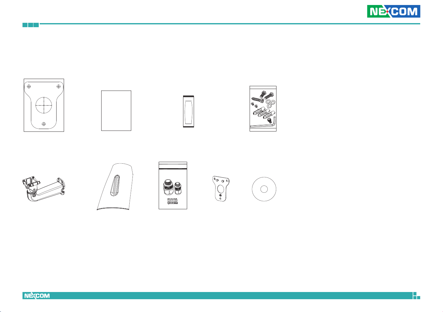
Package Contents
The 3MP Outdoor IR Bullet Camera package contains the following accessories:
Placement sticker Dehumidifier packet
2-axis cable concealed wall
mount bracket
Copyright © 2013 NEXCOM International Co., Ltd. All Rights Reserved.
Quick guide
Sunshield Waterproof connector Wall mount base CD (User Manual)
Mounting accessory kit
x
NCr-302-VHR User Manual

Chapter 1: Product Introduction
ChaPter 1: ProduCt IntroduCtIon
Overview Key Features
▪ Progressive scan CMOS sensor at 3 megapixel/1080p full HD resolution
▪ Multiple H.264 and MJPEG streams
▪ Easy installation with remote focus and zoom control
▪ Support Auto-Focus to avoid focus error through human eyes
▪ Adjustable P-iris to achieve best image quality
▪ Perfect IR exposure calculation
▪ WDR [Wide Dynamic Range] to overcome high contrast lighting environment
▪ Outdoor-ready, IP66/IP67
▪ Active tampering alarm
Copyright © 2013 NEXCOM International Co., Ltd. All Rights Reserved.
▪ Impact-resistant for IK10
▪ Excellent low light noise reduction
▪ ONVIF support
▪ Extreme weather support (-40°C to 60°C)
1
NCr-302-VHR User Manual

Chapter 1: Product Introduction
Hardware Specifications
Camera
▪ Image sensor: 1/3” 3 megapixel true WDR progressive scan CMOS sensor
▪ Lens: Motorized (3-10mm, F1.4) board type
▪ Iris type: p-iris
▪ Day and night: Yes
▪ IR distance: Effective up to 30 meters
▪ IR wavelength: 850nm (4pcs high power LED)
▪ IR control: Smart IR
▪ ICR: Yes
▪ WDR: Yes
▪ Image Enhancement
– Brightness, Contrast, Saturation, Sharpness, Backlight compensation,
Mirror, Flip, Day/Night, Anti-flicker
Video
▪ Video compression: H.264/MJPEG
▪ Video streaming: triple streaming
– H.264 Stream 1/ H.264 Stream 2/ MJPEG Stream 3
▪ Video resolution: 2048 x 1536 to 320 x 240
▪ Video quality
– VBR
– CBR
▪ Frame rate
– 2048 x 1536 @ 30 fps
– 1920 x 1080 @ 60 fps
– 1280 x 720 @ 60 fps
– 720 x 576 @ 60 fps
– 720 x 480 @ 60 fps
– 640 x 480 @ 60 fps
– 320 x 240 @ 60 fps
Audio
▪ Audio streaming: Two-way
▪ Audio compression: G.711 8KHz/ 16bit
▪ Audio input: Line-in
▪ Audio output: Line-out
Network
▪ Interface: 10/100/1000 Mbps Ethernet, RJ-45
▪ Supported protocols: HTTP, TCP/IP, UDP, RTP, RTSP, FTP, SMTP, DHCP, DNS,
DDNS, NTP, uPnP, ONVIF, IPv4/ v6
▪ Security: Multi-level passwords/ HTTP encryption
I/O Connector
▪ Audio in/ out port: Terminal block 1 in/ 1 out
▪ D I/O: DI x1, DO x1
▪ RS485: N/A
▪ Micro SD slot: Yes
▪ RJ45: Yes
Event Management
▪ Event trigger: Motion detection, DI
▪ Notifications: Trigger alarm output, email/ FTP and record video to server
or SD card
▪ Post-recording: Yes
▪ Pre-recording: Yes
Power
▪ DC: DC 12V/ AC 24V
▪ PoE: Yes/ IEEE 802.3at
Copyright © 2013 NEXCOM International Co., Ltd. All Rights Reserved.
2
NCr-302-VHR User Manual

Chapter 1: Product Introduction
General
▪ Power consumption: 14.3W max.
▪ Weight: 2kg
▪ Dimension: 406.22(D) x 161(W) x 263.3(H) mm
▪ Operating Temp.: -40°C~60°C
▪ Humidity: 90% RH (no condensation)
▪ Certification: CE/FCC
▪ Vandal resistant: IK10
▪ Outdoor capable: IP66/IP67, built-in heater
▪ Application: SDK available for application development
Copyright © 2013 NEXCOM International Co., Ltd. All Rights Reserved.
3
NCr-302-VHR User Manual

Chapter 1: Product Introduction
DI/O
54321
Gasket
Tightening
collar
Waterproof
connector
Seal nut
Main body
Gasket
Tightening
collar
Waterproof
connector
Seal nut
Strain relief
Main body
DI/O & Function Description DI/O Pin Definition & Waterproof
Connector Description
360
55
O
Rotate
O
Rotate
SB Module
8 PCS LED IR
Illuminator
Board Plate
Heater module
Ethernet / PoE
Micro SD
MB Module
Line-out
DI/O
Line-in
Reset
Dehumidier
Packet
Bracket
Latch
DC12V/
AC24V
Default
Pin Description
1 ALM_IN (+)
2 ALM_IN (-)
3 ALM_out_NC
4 ALM_out_COM
5 ALM_out_NO
Note:
Default: If the default button has been pressed for 1~4 seconds, the camera
will be re-started and all the settings will be reverted to default except IP
address. If pressed for over 5 seconds, the camera will be re-started and all
the settings will be reverted to default including IP address.
Reset: Press to reset the camera.
Copyright © 2013 NEXCOM International Co., Ltd. All Rights Reserved.
4
NCr-302-VHR User Manual

Chapter 1: Product Introduction
RJ45 PHONE
JACK
Push Lock
q
w
e
r
t
Cable Wiring Description
1. Cable Installation Steps:
2. Run the cable inside the wall mount bracket and out through the cable
opening at the front.
3. Press down the push-lock mechanism and secure the camera onto the
push-lock. Wire the network cables to the waterproof connector on
the right, and wire the line-in, line-out, DC 12V/AV 24V, DI/O and other
cables to the waterproof connector on the left. Tighten the waterproof
connector after all the cables are secured in place.
4. Secure the camera onto the wall mount bracket using the two screws
provided.
5. Open the camera’s top cover to access the wired cables. Install the RJ45
connector to the Ethernet cable and plug it into the corresponding port
on the MB module.
6. Close the camera’s top cover and secure it with the supplied hardware
tool to complete.
Copyright © 2013 NEXCOM International Co., Ltd. All Rights Reserved.
5
NCr-302-VHR User Manual

Chapter 1: Product Introduction
Cable Outlet Description
1. The camera features two waterproof connectors, the left one in the
diagram is for PoE connection, while right one is for line in, line out, DC
12V/AC 24V and DI/O connections.
2. The right one features four wire holes. Please cover unused holes with
sealing plugs to prevent water from entering.
3. Applicable cable diameter:
4. * Ø 2.5~1.8mm (Right)
5. * Ø 6.9~4.7mm (Left)
Line-out
Line-in
DC12V/AC24V
DI/O
Ethernet
Hardware Installation
1. Position the placement sticker at the desired installation location and use
a driller to drill the three holes on the sticker.
2. Insert three screw anchors into the holes then place the wall mount base
on top of them with the mounting holes aligned.
3. Open the camera’s cover and glue the dehumidifier packet onto the metal
bracket using the adhesive sticker on its back, as depicted in the diagram
below. Close the camera’s cover and ensure the clip is locked in position.
Install the sunshield and tighten a torx screw on the side of cover.
Copyright © 2013 NEXCOM International Co., Ltd. All Rights Reserved.
6
NCr-302-VHR User Manual

Chapter 1: Product Introduction
4. Secure the connecting bracket to the camera’s rear.
5. Press and hold down the latch on the wall mount bracket and put it into
the connecting bracket. Once in place, secure the other side using the
supplied hex wrench.
6. Align the mounting holes on the wall mount bracket to the mounting
holes on the wall mount plate, then secure it tightly with screws to finish
the installation.
Press
Copyright © 2013 NEXCOM International Co., Ltd. All Rights Reserved.
7
NCr-302-VHR User Manual

Chapter 2: Camera Configuration
ChaPter 2: Camera ConfIguratIon
Accessing the Camera’s Configuration Menu (Graphical User Interface)
The camera’s default IP address is 192.168.1.168, make sure the IP address
of the computer accessing the camera is on the same network subnet
before proceeding.
You can access the camera via a web browser or IP-FINDER software included
with the camera. The following information outlines the instructions for
each method.
Installing IP-FINDER
Note: If IP-FINDER is already installed, you can skip this section and continue
to the next section IP-FINDER on page 11.
1. Locate the installation file IP-FINDER-Setup.msi on the CD.
2. Once located, double click on the file to start the installation program.
3. Click the Next button on the welcome screen to continue.
Copyright © 2013 NEXCOM International Co., Ltd. All Rights Reserved.
Next button
8
NCr-302-VHR User Manual

Chapter 2: Camera Configuration
4. Confirm the directory that the program will be installed on. To specify
a different folder, please click on the Browse button and locate the
desired installation folder.
5. To check the available drives you can install the software to and their
available and required disk space, please click on the Disk Cost button.
6. Specify which user accounts on the computer can access the program,
the options are Everyone and Just me.
Browse button
Disk Cost
button
Next button
User accounts
7. Click on the Next button to continue.
Copyright © 2013 NEXCOM International Co., Ltd. All Rights Reserved.
9
NCr-302-VHR User Manual

Chapter 2: Camera Configuration
8. Click on the Next button to begin installation.
9. Once the installation process is complete, click on the Close button to
finish. A shortcut will be created on the desktop.
Next button
Close button
Copyright © 2013 NEXCOM International Co., Ltd. All Rights Reserved.
10
NCr-302-VHR User Manual
 Loading...