

Page 1
Page 2

Revised – April 26, 2015
Trademarks: NewTek, TriCaster, TriCaster XD, TriCaster 8000, TriCaster TCXD8000, TCXD8000, TriCaster 860, TriCaster TCXD860, TCXD860, TriCaster 460,
TriCaster TCXD460, TCXD460, TriCaster 410, TriCaster TCXD410, TCXD410, TriCaster Mini, TriCaster 40, TriCaster TCXD40, TCXD40, TriCaster 855, TriCaster
TCXD855, TCXD855, TriCaster 455, TriCaster TCXD455, TCXD455, TriCaster EXTREME, TriCaster 850 EXTREME, TriCaster TCXD850 EXTREME, TCXD850
EXTREME, TriCaster 450 EXTREME, TriCaster TCXD450 EXTREME, TCXD450 EXTREME, TriCaster 850, TriCaster TCXD850, TCXD850, TriCaster 450, TriCaster
TCXD450, TCXD450, TriCaster 300, TriCaster TCXD300, TCXD300, TriCaster PRO, TriCaster STUDIO, TriCaster BROADCAST, TriCaster DUO, 3PLAY, 3Play, 3Play
4800, 3PXD4800, 3Play 440, 3PXD440, 3Play 820, 3PXD820, 3Play Mini, 3Play 425, 3PXD425 3Play 330, 3PXD330, TalkShow, TalkShow VS100, ProTek, ProTek
Care, ProTek Elite, iVGA, SpeedEDIT, IsoCorder, LiveText, DataLink, LiveSet, TriCaster Virtual Set Editor, TriCaster VSE, LiveMatte, TimeWarp, VT, VT[3], VT[4],
V[T5], Video Toaster, Toaster, Inspire 3D, 3D Arsenal, Aura, LightWave, LightWave 3D and LightWave CORE are trademarks, service marks, and registered
trademarks of NewTek. All other brand names, product names, or trademarks belong to their respective holders.
Page 3

CONTENTS
ABOUT THIS MANUAL ....................................................................................................................................... 3
INTRODUCTION ................................................................................................................................................. 5
SECTION 2.1 MEET THE FAMILY ...................................................................................................................................................... 5
SECTION 2.2 OVERVIEW ................................................................................................................................................................ 5
SECTION 2.3 TRICASTER™ ADVANCED EDITION ................................................................................................................................. 5
SECTION 2.4 STARTUP SCREEN ....................................................................................................................................................... 6
SECTION 2.5 LIVE DESKTOP ............................................................................................................................................................ 6
SECTION 2.6 FEATURES ................................................................................................................................................................. 7
2.6.1 Physical....................................................................................................................................................................... 7
2.6.2 Multi-Tier Failsafe ...................................................................................................................................................... 8
2.6.3 A/V Input and Output ................................................................................................................................................. 8
2.6.4 Alpha Channel I/O ...................................................................................................................................................... 9
2.6.5 Timecode .................................................................................................................................................................... 9
2.6.6 Monitoring ................................................................................................................................................................. 9
2.6.7 Video Processing ...................................................................................................................................................... 10
2.6.8 The Switcher ............................................................................................................................................................. 10
2.6.9 M/Es ......................................................................................................................................................................... 12
2.6.10 Virtual Sets ............................................................................................................................................................. 12
2.6.11 Record and Stream ................................................................................................................................................. 12
2.6.12 Media Publishing .................................................................................................................................................... 13
2.6.13 Automation ............................................................................................................................................................ 13
2.6.14 Hotspots, Triggers and Trackers ............................................................................................................................. 13
2.6.15 Import..................................................................................................................................................................... 13
2.6.16 Audio Mixer ............................................................................................................................................................ 14
2.6.17 Integrated Media Players ....................................................................................................................................... 14
2.6.18 Buffers .................................................................................................................................................................... 15
2.6.19 Titles and Graphics ................................................................................................................................................. 16
2.6.20 Optional Control Surfaces ...................................................................................................................................... 16
SETTING UP ..................................................................................................................................................... 17
SECTION 3.1 COMMAND AND CONTROL ......................................................................................................................................... 17
SECTION 3.2 LICENSE AND REGISTRATION ....................................................................................................................................... 18
3.2.1 Online Registration ................................................................................................................................................... 18
3.2.2 Registering by Telephone ......................................................................................................................................... 18
SECTION 3.3 RACK MOUNTING TRICASTER ..................................................................................................................................... 19
SECTION 3.4 INPUT CONNECTIONS ................................................................................................................................................ 20
3.4.1 Connect A/V Sources ................................................................................................................................................ 20
3.4.2 Con n e c t ing a V i d e o R o u t e r ............................................................................................................................. 22
SECTION 3.5 GENLOCK CONNECTION ............................................................................................................................................. 23
SECTION 3.6 TIMECODE CONNECTION ............................................................................................................................................ 24
SECTION 3.7 OUTPUT CONNECTIONS ............................................................................................................................................. 24
3.7.1 A/V Output ............................................................................................................................................................... 24
3.7.2 HD and SD ................................................................................................................................................................ 24
3.7.3 Supplemental Video Outputs.................................................................................................................................... 25
SECTION 3.8 TALLY LIGHTS........................................................................................................................................................... 26
3.8.1 Connection Details ................................................................................................................................................... 26
i
Page 4

SECTION 3.9 STARTING A SESSION ................................................................................................................................................. 27
SECTION 3.10 CONFIGURE VIDEO OUTPUT ..................................................................................................................................... 29
3.10.1 Output Channel Options ......................................................................................................................................... 30
SECTION 3.11 CONFIGURE VIDEO INPUTS ....................................................................................................................................... 31
3.11.1 Co n f igure a V ideo Ro u t e r Input ................................................................................................................... 32
SECTION 3.12 CONFIGURE AUDIO ................................................................................................................................................. 32
SECTION 3.13 CONFIGURE GENLOCK ............................................................................................................................................. 34
SECTION 3.14 CONFIGURE TIMECODE ............................................................................................................................................ 35
SECTION 3.15 NETWORKING ........................................................................................................................................................ 35
BASIC TRAINING .............................................................................................................................................. 37
SECTION 4.1 RESOURCES WEBPAGE .............................................................................................................................................. 37
4.1.1 Valuable Content ...................................................................................................................................................... 38
SECTION 4.2 VIDEO TRAINING ...................................................................................................................................................... 39
SECTION 4.3 OPERATOR CERTIFICATION ......................................................................................................................................... 39
THE STARTUP SCREEN ..................................................................................................................................... 43
SECTION 5.1 INTRODUCTION TO SESSIONS ...................................................................................................................................... 43
SECTION 5.2 THE HOME PAGE...................................................................................................................................................... 45
5.2.1 New (Session) ........................................................................................................................................................... 45
5.2.2 Open (Session) .......................................................................................................................................................... 47
5.2.3 Shutdown ................................................................................................................................................................. 48
5.2.4 Help .......................................................................................................................................................................... 51
5.2.5 Add-Ons .................................................................................................................................................................... 51
SECTION 5.3 THE SESSION PAGE ................................................................................................................................................... 52
5.3.1 Live ........................................................................................................................................................................... 52
5.3.2 Graphics ................................................................................................................................................................... 52
5.3.3 Manage .................................................................................................................................................................... 54
LIVE DESKTOP: OVERVIEW............................................................................................................................... 57
SECTION 6.1 DISPLAY REQUIREMENTS ............................................................................................................................................ 57
SECTION 6.2 OVERVIEW .............................................................................................................................................................. 57
SECTION 6.3 CONTROL TYPES ....................................................................................................................................................... 58
SECTION 6.4 CUSTOMIZING THE LIVE DESKTOP ................................................................................................................................ 59
6.4.1 Rename Input ........................................................................................................................................................... 59
6.4.2 Workspaces and Min/Maximize ............................................................................................................................... 60
THE DASHBOARD............................................................................................................................................. 63
SECTION 7.1 FILE MENU ............................................................................................................................................................. 63
SECTION 7.2 OPTIONS MENU ....................................................................................................................................................... 64
SECTION 7.3 MACROS ................................................................................................................................................................ 65
SECTION 7.4 WORKSPACES .......................................................................................................................................................... 65
SECTION 7.5 INFORMATION PANEL ................................................................................................................................................ 65
I/O CONFIGURATION ....................................................................................................................................... 67
SECTION 8.1 OUTPUT CONFIGURATION .......................................................................................................................................... 67
8.1.1 Output Tab ............................................................................................................................................................... 68
8.1.2 Genlock & Failsafe .................................................................................................................................................... 71
8.1.3 Center Frequency ..................................................................................................................................................... 73
8.1.4 Failsafe ..................................................................................................................................................................... 74
ii
Page 5

SECTION 8.2 INPUT CONFIGURATION ............................................................................................................................................. 74
8.2.1 Connection Type ....................................................................................................................................................... 75
8.2.2 Act as Alpha ............................................................................................................................................................. 77
8.2.3 Frame Sync ............................................................................................................................................................... 78
8.2.4 Edges ........................................................................................................................................................................ 78
8.2.5 PTZ ............................................................................................................................................................................ 79
8.2.6 Color Control ............................................................................................................................................................ 80
8.2.7 LiveMatte ................................................................................................................................................................. 83
8.2.8 Automation .............................................................................................................................................................. 83
8.2.9 Tracker ..................................................................................................................................................................... 85
SECTION 8.3 NETWORK INPUTS .................................................................................................................................................... 86
SECTION 8.4 TIMECODE CONFIGURATION ....................................................................................................................................... 87
8.4.1 Subtract 12 Hours ..................................................................................................................................................... 87
8.4.2 Event Time ................................................................................................................................................................ 87
8.4.3 LTC Timecode ........................................................................................................................................................... 88
SWITCHER, TRANSITIONS AND OVERLAY ......................................................................................................... 89
SECTION 9.1 SWITCHER ROWS ..................................................................................................................................................... 89
SECTION 9.2 PROGRAM AND PREVIEW ........................................................................................................................................... 89
SECTION 9.3 BACKGROUND AND DSK LAYERS ................................................................................................................................. 90
9.3.1 Selecting Sources ...................................................................................................................................................... 91
9.3.2 Linking Switcher Rows .............................................................................................................................................. 91
SECTION 9.4 TRANSITIONS AND EFFECTS ......................................................................................................................................... 92
9.4.1 DSK Controls ............................................................................................................................................................. 92
9.4.2 Main Controls ........................................................................................................................................................... 96
SECTION 9.5 EFFECT VIEW ........................................................................................................................................................... 99
SECTION 9.6 UNDO/REDO ......................................................................................................................................................... 100
SECTION 9.7 SWITCHER MEMORY ............................................................................................................................................... 101
SECTION 9.8 SWITCHER MEM SLOTS ........................................................................................................................................... 101
MONITORING YOUR VIDEO ......................................................................................................................... 103
SECTION 10.1 INTERFACE AND MULTIVIEW ................................................................................................................................... 103
10.1.1 Workspace Presets ............................................................................................................................................... 104
SECTION 10.2 SCOPES .............................................................................................................................................................. 104
10.2.1 Viewport Tools ..................................................................................................................................................... 106
SECTION 10.3 PROGRAM MONITOR ............................................................................................................................................ 107
SECTION 10.4 LOOK AHEAD PREVIEW .......................................................................................................................................... 107
MEDIA PLAYERS & BUFFERS ........................................................................................................................ 109
SECTION 11.1 SPECIALIZED MEDIA PLAYERS .................................................................................................................................. 109
SECTION 11.2 SHARED FEATURES ................................................................................................................................................ 110
11.2.1 Playlists ................................................................................................................................................................ 110
11.2.2 Me d i a Browse r ............................................................................................................................................... 114
11.2.3 P l a y e r Cont r o l s ............................................................................................................................................... 116
11.2.4 Show On (…) ......................................................................................................................................................... 118
11.2.5 MEM Slots ............................................................................................................................................................ 119
11.2.6 Network Sharing .................................................................................................................................................. 120
SECTION 11.3 EDITING TITLE PAGES ............................................................................................................................................ 120
11.3.1 Header Tools ........................................................................................................................................................ 121
11.3.2 Footer Tools .......................................................................................................................................................... 121
iii
Page 6

11.3.3 DataLink ............................................................................................................................................................... 122
SECTION 11.4 BUFFERS ............................................................................................................................................................. 123
11.4.1 Buffer Types ......................................................................................................................................................... 124
11.4.2 Selecting Content ................................................................................................................................................. 125
11.4.3 Buffers Menu ........................................................................................................................................................ 126
11.4.4 Animation Features .............................................................................................................................................. 126
11.4.5 Sharing Buffers ..................................................................................................................................................... 127
11.4.6 Watch Folders ...................................................................................................................................................... 127
11.4.7 Using Buffers ........................................................................................................................................................ 127
11.4.8 Keying, Proc Amps and More ............................................................................................................................... 128
11.4.9 Editing titles ......................................................................................................................................................... 128
PTZ CONTROL .............................................................................................................................................. 129
SECTION 12.1 THE PTZ TAB ...................................................................................................................................................... 129
12.1.1 The Camera Bin .................................................................................................................................................... 129
12.1.2 PTZ Presets ........................................................................................................................................................... 130
12.1.3 Configuring Presets .............................................................................................................................................. 130
12.1.4 PTZ and the Control Surface ................................................................................................................................. 131
LIVEMATTE .................................................................................................................................................. 133
SECTION 13.1 CHROMAKEYING ................................................................................................................................................... 133
SECTION 13.2 MATTE ............................................................................................................................................................... 134
13.2.1 Color ..................................................................................................................................................................... 134
13.2.2 Tolerance .............................................................................................................................................................. 135
13.2.3 Smoothness .......................................................................................................................................................... 135
13.2.4 Luma Limit ............................................................................................................................................................ 135
SECTION 13.3 SPILL SUPPRESSION ............................................................................................................................................... 135
SECTION 13.4 COMPOSITING ..................................................................................................................................................... 136
SECTION 13.5 FINE TUNING ....................................................................................................................................................... 136
SECTION 13.6 PRACTICAL STAGING FOR LIVEMATTE ....................................................................................................................... 137
13.6.1 Lighting ................................................................................................................................................................ 137
13.6.2 Connection Considerations ................................................................................................................................... 137
MIX/EFFECT (M/E) TOOLS ............................................................................................................................ 139
SECTION 14.1 OVERVIEW .......................................................................................................................................................... 139
SECTION 14.2 M/E MODES ....................................................................................................................................................... 139
14.2.1 Mix Mode ............................................................................................................................................................. 140
14.2.2 Effect Mode .......................................................................................................................................................... 141
14.2.3 Input Position Controls ......................................................................................................................................... 141
14.2.4 Default Effects ...................................................................................................................................................... 141
14.2.5 Virtual Sets ........................................................................................................................................................... 146
14.2.6 Holographic LiveSets ............................................................................................................................................ 149
SECTION 14.3 KEY CHANNELS .................................................................................................................................................... 150
14.3.1 Key Layers and Autoplay ...................................................................................................................................... 150
14.3.2 Augmented Reality ............................................................................................................................................... 150
AUDIO ......................................................................................................................................................... 153
15.1.1 Audio Specifications ............................................................................................................................................. 154
SECTION 15.2 HEADPHONES ...................................................................................................................................................... 154
SECTION 15.3 VU METER CALIBRATION ....................................................................................................................................... 154
iv
Page 7

SECTION 15.4 EXTERNAL SOURCES .............................................................................................................................................. 154
15.4.1 Connection Type ................................................................................................................................................... 155
SECTION 15.5 COMMON CONTROLS ............................................................................................................................................ 156
15.5.1 Mute ..................................................................................................................................................................... 156
15.5.2 Lock ...................................................................................................................................................................... 156
15.5.3 Talk (Talk Over) .................................................................................................................................................... 157
15.5.4 Solo ....................................................................................................................................................................... 157
SECTION 15.6 INTERNAL SOURCES .............................................................................................................................................. 158
15.6.1 Net 1 and Net 2 .................................................................................................................................................... 158
15.6.2 Media Players ....................................................................................................................................................... 158
15.6.3 Effects (Transitions) .............................................................................................................................................. 158
SECTION 15.7 ADVANCED CONFIGURATION .................................................................................................................................. 159
15.7.1 Audio Delay .......................................................................................................................................................... 159
15.7.2 Automation .......................................................................................................................................................... 159
15.7.3 Pan ....................................................................................................................................................................... 160
15.7.4 Routing ................................................................................................................................................................. 160
15.7.5 Processing ............................................................................................................................................................ 163
SECTION 15.8 OUTPUT AND PRIMARY BUS CONTROLS .................................................................................................................... 165
15.8.1 Headroom Notes .................................................................................................................................................. 166
15.8.2 Record .................................................................................................................................................................. 167
15.8.3 Stream .................................................................................................................................................................. 167
SECTION 15.9 MEM SLOT BINS ................................................................................................................................................. 167
NETWORK INPUTS ....................................................................................................................................... 169
SECTION 16.1 IVGA ................................................................................................................................................................. 169
16.1.1 iVGA for OS X ........................................................................................................................................................ 170
16.1.2 iVGA PRO (Windows)............................................................................................................................................ 171
16.1.3 Taskbar Icon Menu ............................................................................................................................................... 174
16.1.4 Hotkeys ................................................................................................................................................................. 175
SECTION 16.2 AIRPLAY ............................................................................................................................................................. 175
SECTION 16.3 LIVETEXT (STANDALONE) ....................................................................................................................................... 176
SECTION 16.4 3PLAY™ ............................................................................................................................................................. 176
SECTION 16.5 TALKSHOW™ ...................................................................................................................................................... 176
SECTION 16.6 NETWORK VIDEO ................................................................................................................................................. 176
MACROS, AUTOMATION AND REMOTE CONTROL ....................................................................................... 179
SECTION 17.1 RECORDING MACROS ............................................................................................................................................ 180
17.1.1 Snapshot Mode .................................................................................................................................................... 180
17.1.2 Triggers ................................................................................................................................................................ 180
SECTION 17.2 MANAGING MACROS ............................................................................................................................................ 181
17.2.1 Session Macros ..................................................................................................................................................... 181
SECTION 17.3 AUTOMATION ...................................................................................................................................................... 181
SECTION 17.4 REMOTE CONTROL ............................................................................................................................................... 181
17.4.1 ‘Twinning’ TriCasters ............................................................................................................................................ 181
STREAM ....................................................................................................................................................... 183
SECTION 18.1 INTRODUCTION .................................................................................................................................................... 183
SECTION 18.2 THE WEB BROWSER ............................................................................................................................................. 183
SECTION 18.3 CONNECTIONS ..................................................................................................................................................... 183
18.3.1 Custom Connections ............................................................................................................................................. 184
v
Page 8

18.3.2 Legacy .................................................................................................................................................................. 184
18.3.3 Act as Webcam .................................................................................................................................................... 185
SECTION 18.4 AUDIO LEVEL ....................................................................................................................................................... 186
SECTION 18.5 CAPTURING THE STREAM ....................................................................................................................................... 186
SECTION 18.6 STREAMING STRATEGIES ........................................................................................................................................ 186
18.6.1 On Demand or Live Streaming? ............................................................................................................................ 186
18.6.2 Windows Media® Streaming ................................................................................................................................. 188
18.6.3 Streaming Media Providers .................................................................................................................................. 190
18.6.4 Other Resources ................................................................................................................................................... 190
SECTION 18.7 PRODUCTION AND CAPTURE CONSIDERATIONS ........................................................................................................... 190
SECTION 18.8 DIAGNOSTICS AND TROUBLESHOOTING ..................................................................................................................... 191
18.8.1 Testing your stream ............................................................................................................................................. 191
18.8.2 Is it Really a TriCaster Issue? ................................................................................................................................ 196
PUBLISH ....................................................................................................................................................... 197
SECTION 19.1 OVERVIEW .......................................................................................................................................................... 197
SECTION 19.2 PUBLISH MENU.................................................................................................................................................... 197
19.2.1 Preset List ............................................................................................................................................................. 197
19.2.2 New Preset ........................................................................................................................................................... 198
19.2.3 Social Media Sites................................................................................................................................................. 198
19.2.4 Transcode and FTP ............................................................................................................................................... 198
19.2.5 Watermarking ...................................................................................................................................................... 198
SECTION 19.3 PUBLISH BIN ........................................................................................................................................................ 198
19.3.1 Metadata ............................................................................................................................................................. 199
19.3.2 Presets .................................................................................................................................................................. 200
19.3.3 List Management ................................................................................................................................................. 200
19.3.4 The Publish Button ............................................................................................................................................... 201
SECTION 19.4 PUBLISH QUEUE ................................................................................................................................................... 201
19.4.1 The Queue Switch ................................................................................................................................................. 202
19.4.2 Auto Queue .......................................................................................................................................................... 202
19.4.3 Other ‘Add to’ Methods........................................................................................................................................ 203
RECORD AND GRAB ..................................................................................................................................... 205
SECTION 20.1 RECORD.............................................................................................................................................................. 205
20.1.1 Record Configuration ........................................................................................................................................... 205
20.1.2 Capture Tab .......................................................................................................................................................... 206
20.1.3 Replay Tab ............................................................................................................................................................ 209
SECTION 20.2 GRAB ................................................................................................................................................................. 211
AUTHORING TITLE PAGES ............................................................................................................................ 213
SECTION 21.1 SESSIONS, PROJECTS AND DISPLAY .................................................................................................................. 213
21.1.1 Files/Filebin .......................................................................................................................................................... 214
21.1.2 Naming Stand-in Images ...................................................................................................................................... 214
CONTROL SURFACES .................................................................................................................................... 217
SECTION 22.1 SOMETHING FOR EVERYONE ................................................................................................................................... 217
22.1.1 Primary Control .................................................................................................................................................... 217
22.1.2 Instant Replay ...................................................................................................................................................... 218
SECTION 22.2 CONNECTIONS & POWER ....................................................................................................................................... 218
22.2.1 Power Considerations ........................................................................................................................................... 218
vi
Page 9

SECTION 22.3 TRICASTER™ 8000 CS .......................................................................................................................................... 219
22.3.1 Overview .............................................................................................................................................................. 219
22.3.2 Delegates and Synchronization ............................................................................................................................ 219
22.3.3 MAIN TRANSITION Group ..................................................................................................................................... 221
22.3.4 M/E Controls ........................................................................................................................................................ 223
22.3.5 POSITIONER Group ............................................................................................................................................... 224
22.3.6 MEDIA PLAYERS Group ......................................................................................................................................... 227
22.3.7 Record Group ....................................................................................................................................................... 228
22.3.8 Special Buttons ..................................................................................................................................................... 228
22.3.9 MACRO ................................................................................................................................................................. 228
22.3.10 T-Bar Illumination............................................................................................................................................... 229
22.3.11 M/E TRANSITION – Lighting ............................................................................................................................... 229
22.3.12 MAIN TRANSITION ............................................................................................................................................. 229
22.3.13 PTZ Control ......................................................................................................................................................... 230
22.3.14 AirSend™ Control ................................................................................................................................................ 230
SECTION 22.4 TRICASTER™ 460 CS & 860 CS ............................................................................................................................. 231
22.4.1 Overview .............................................................................................................................................................. 231
22.4.2 Special Buttons ..................................................................................................................................................... 232
22.4.3 Delegates and Synchronization ............................................................................................................................ 232
22.4.4 Switcher Controls ................................................................................................................................................. 233
22.4.5 Transition Group .................................................................................................................................................. 235
22.4.6 M/E Group ............................................................................................................................................................ 237
22.4.7 Positioner Group .................................................................................................................................................. 239
22.4.8 Media Player Group ............................................................................................................................................. 242
22.4.9 Record Group ....................................................................................................................................................... 243
22.4.10 PTZ Control ......................................................................................................................................................... 243
22.4.11 AirSend™ Control ................................................................................................................................................ 244
SECTION 22.5 TRICASTER™ 40 CS & TRICASTER MINI CS ............................................................................................................... 244
22.5.1 Delegates and Synchronization ............................................................................................................................ 245
22.5.2 Switcher Delegates ............................................................................................................................................... 245
22.5.3 SHIFT & ALT .......................................................................................................................................................... 246
22.5.4 Transitions ............................................................................................................................................................ 248
SECTION 22.6 TIMEWARP™ ....................................................................................................................................................... 249
22.6.1 22.5.1 CONFIGURING TRICASTER ......................................................................................................................... 249
22.6.2 Overview .............................................................................................................................................................. 250
22.6.3 DDR Delegate ....................................................................................................................................................... 251
22.6.4 Edit group ............................................................................................................................................................. 251
22.6.5 Play Speed ............................................................................................................................................................ 252
22.6.6 Marking Group ..................................................................................................................................................... 252
22.6.7 ALT and Qualifiers ................................................................................................................................................ 254
22.6.8 Record toggle ....................................................................................................................................................... 254
22.6.9 DDR options .......................................................................................................................................................... 254
22.6.10 Preset (DDR Playlist) ........................................................................................................................................... 255
22.6.11 Transport (Clip controls) ..................................................................................................................................... 255
22.6.12 Tips and Tricks .................................................................................................................................................... 256
SECTION 22.7 AVID
22.7.1 Installing AVID® Artist Mix Software .................................................................................................................... 257
22.7.2 Connecting Artist Mix ........................................................................................................................................... 257
22.7.3 Getting started ..................................................................................................................................................... 258
22.7.4 Pa n e l Layout ................................................................................................................................................... 258
®
ARTIST MIX ................................................................................................................................................ 256
vii
Page 10

22.7.5 NUDGE ................................................................................................................................................................. 259
22.7.6 BANK .................................................................................................................................................................... 259
22.7.7 Level Control ......................................................................................................................................................... 260
22.7.8 Knob Set Selectors ................................................................................................................................................ 260
22.7.9 Pan Control ........................................................................................................................................................... 261
22.7.10 Talk ..................................................................................................................................................................... 261
22.7.11 Solo & Mute ....................................................................................................................................................... 261
22.7.12 Follow ................................................................................................................................................................. 262
22.7.13 EQ Control .......................................................................................................................................................... 262
22.7.14 Compressor/Limiter ............................................................................................................................................ 263
22.7.15 CHAN Mode ........................................................................................................................................................ 263
22.7.16 FLIP Mode ........................................................................................................................................................... 264
22.7.17 INSERT ................................................................................................................................................................ 264
22.7.18 Locking Channels ................................................................................................................................................ 265
22.7.19 Audio Presets ...................................................................................................................................................... 265
SECTION 22.8 MIDI CONTROL ................................................................................................................................................... 265
SECTION 22.9 GPI CONTROLLERS ........................................................................................................................................... 267
A HOW DO I … (?) ....................................................................................................................................................... 269
A.1 CONNECTIONS ............................................................................................................................................................ 271
A.1.1 Connect cameras? .............................................................................................................................................. 271
A.1.2 Connect fill + alpha sources? .............................................................................................................................. 271
A.1.3 Configure alpha matte output?.......................................................................................................................... 272
A.1.4 Color correct mismatched cameras? .................................................................................................................. 272
A.1.5 Connect monitors? ............................................................................................................................................. 272
A.1.6 Connect a supported external control surface? ................................................................................................. 274
A.1.7 Mirror control operations to another TriCaster? ............................................................................................... 274
A.1.8 Insert/Remove a Drive From TriCaster’s Removable Drive Bay ......................................................................... 274
A.1.9 Connect An External Hard Drive? ....................................................................................................................... 275
A.1.10 Eject A Hard Drive? ........................................................................................................................................ 275
A.1.11 Connect tally lights? ...................................................................................................................................... 276
A.1.12 Connect to a network? ................................................................................................................................... 276
A.1.13 Resolve iVGA PRO Quirks ............................................................................................................................... 276
ADDITIONAL NOTES ...................................................................................................................................................... 276
A.1.14 Connect to an AirPlay® Source? ..................................................................................................................... 277
A.1.15 Enable Termination for video inputs? ............................................................................................................ 279
A.1.16 Configure Wirecast® to receive TriCaster’s Network output? ....................................................................... 279
A.2 SESSIONS ................................................................................................................................................................... 279
A.2.1 Start an SD Session? ........................................................................................................................................... 280
A.2.2 Start an HD Session? .......................................................................................................................................... 280
A.2.3 Work on a Stored Session? ................................................................................................................................. 281
A.2.4 Backup a Session? .............................................................................................................................................. 281
A.2.5 Restore a Session? .............................................................................................................................................. 282
A.2.6 Delete a Session (and its Content)? .................................................................................................................... 282
A.2.7 Manage Selected Content inside a Session? ...................................................................................................... 282
A.2.8 Rename a Session? ............................................................................................................................................. 283
A.2.9 Duplicate a session? ........................................................................................................................................... 283
A.3 LIVE PRODUCTION ....................................................................................................................................................... 283
A.3.1 Make Custom Transitions and LiveSets? ............................................................................................................ 283
A.3.2 Restore the Default LiveSet? .............................................................................................................................. 283
viii
Page 11

A.3.3 Set up the ‘Nightly Show A’ LiveSet? .................................................................................................................. 283
A.3.4 Set up the ‘Night Beat 3D’ LiveSet? .................................................................................................................... 285
A.3.5 Set up the ‘Metropolis A’ LiveSet? ...................................................................................................................... 285
A.3.6 Initiate Streaming?............................................................................................................................................. 287
A.3.7 Find my Captured Stream file? ........................................................................................................................... 287
A.3.8 Record my Program? .......................................................................................................................................... 287
A.3.9 Find my Recorded Program File?........................................................................................................................ 288
A.3.10 Change Playback Speed for Clips in the DDR (Media Player)? ....................................................................... 288
A.3.11 Deal With DDR (Media Player) Clips That Seem Blurry? ................................................................................ 288
A.3.12 Get Stubborn Clips to Play in the DDR? ......................................................................................................... 288
A.3.13 Change Colors for an Entire Title Playlist at Once? ........................................................................................ 290
A.3.14 Get Live Title Pages (.cgxml) to Respect All LiveText Font Attributes? .......................................................... 290
A.3.15 Prepare a Matched Group of M/Es? .............................................................................................................. 290
A.3.16 Improve the Quality of Multiview Output? .................................................................................................... 291
A.4 FILES ......................................................................................................................................................................... 291
A.4.1 Manage Files? .................................................................................................................................................... 291
A.4.2 Import Media Files? ........................................................................................................................................... 291
A.4.3 Avoid Delays When Session Media is Offline? .................................................................................................... 291
A.4.4 Share Files On YouTube®? ................................................................................................................................... 292
A.4.5 Prepare Clips with Embedded Alpha Channel? .................................................................................................. 292
A.4.6 Add an External File Location to the File Browser? ............................................................................................ 292
A.4.7 Remove a Location From the File Browser? ....................................................................................................... 293
A.4.8 Export files to an External Drive? ....................................................................................................................... 293
A.4.9 Import/Export Files Larger Than 4 Gigabytes? .................................................................................................. 293
A.4.10 Repair damaged recordings? ......................................................................................................................... 293
A.4.11 Avoid the Error “…copy this file without its properties?” .............................................................................. 293
A.4.12 Free up Space by Deleting the Demo Clips? ................................................................................................... 294
A.5 SOFTWARE, MAINTENANCE AND UPDATES ....................................................................................................................... 294
A.5.1 Improve Performance? ....................................................................................................................................... 294
A.5.2 Resolve Serious Instability or Dropped frames? ................................................................................................. 294
A.5.3 Update TriCaster? .............................................................................................................................................. 294
A.5.4 Update the Flash® and/or Windows Media Encoder®? .................................................................................... 295
A.5.5 Install Virus Protection? ..................................................................................................................................... 295
A.5.6 Install My Favorite Software (or Codec)? ........................................................................................................... 295
A.5.7 Create a ‘User Backup’ Drive .............................................................................................................................. 296
A.5.8 Restore TriCaster Software ................................................................................................................................ 296
A.6 REGISTRATION AND TECH SUPPORT ................................................................................................................................ 298
A.6.1 Register TriCaster? ............................................................................................................................................. 298
A.6.2 Contact Customer Support? ............................................................................................................................... 298
A.6.3 Find TriCaster’s Hardware/Firmware Revision Numbers? ................................................................................. 298
A.7 MISCELLANEOUS ......................................................................................................................................................... 298
A.7.1 Access System Administration Features? ........................................................................................................... 298
A.7.2 Return to TriCaster from Administrator Mode ................................................................................................... 298
A.8 MORE QUESTIONS AND ANSWERS .................................................................................................................................. 299
A.8.1 Can I do anything to improve latency/audio sync? ............................................................................................ 299
A.8.2 Why is my power supply beeping? ..................................................................................................................... 299
A.8.3 Why Do Some Thumbnail Icons Look Wrong? ................................................................................................... 300
B PERFORMANCE CONSIDERATIONS .......................................................................................................................... 301
B.1 TESTING, ONE TWO … ................................................................................................................................................. 301
ix
Page 12

B.2 IVGA™ AND PERFORMANCE ......................................................................................................................................... 301
B.3 IMAG AND LATENCY ................................................................................................................................................... 301
B.3.1 Relativity and the Speed of Light ....................................................................................................................... 301
B.3.2 Latency and Your Audience ................................................................................................................................ 302
B.3.3 Latency and Your TriCaster ................................................................................................................................ 302
B.3.4 Other Sources of Latency ................................................................................................................................... 303
C VIDEO CALIBRATION ............................................................................................................................................... 305
C.1 WHAT (AND WHERE) TO CALIBRATE? ............................................................................................................................. 305
C.2 CALIBRATING VIDEO SOURCES ....................................................................................................................................... 306
C.2.1 Setting Black and White ..................................................................................................................................... 306
C.2.2 Adjusting Color ................................................................................................................................................... 307
C.2.3 Color Metrics ...................................................................................................................................................... 308
C.3 CALIBRATING YOUR MONITORS ..................................................................................................................................... 309
C.3.1 Computer Monitor ............................................................................................................................................. 309
C.3.2 Program Output Monitor ................................................................................................................................... 310
C.3.3 Color Adjustments .............................................................................................................................................. 310
C.4 FURTHER READING ...................................................................................................................................................... 311
D KEYSTROKE SHORTCUTS .......................................................................................................................................... 313
D.1 SWITCHER… ............................................................................................................................................................... 313
D.2 T-BAR ....................................................................................................................................................................... 313
D.3 RECORD, GRAB, AND STREAM ....................................................................................................................................... 314
D.4 TABS ......................................................................................................................................................................... 314
D.5 WORKSPACE .............................................................................................................................................................. 314
D.6 MEDIA PLAYERS .......................................................................................................................................................... 314
D.7 GENERAL ................................................................................................................................................................... 315
D.7.1 Edit Title Pane .................................................................................................................................................... 315
D.7.2 Selection and Navigation ................................................................................................................................... 315
D.7.3 Misc. ................................................................................................................................................................... 315
E DIMENSIONS AND MOUNTING................................................................................................................................ 317
SECTION 22.10 TRICASTER MINI ................................................................................................................................................ 317
SECTION 22.11 TRICASTER 460 AND 410 .................................................................................................................................... 317
SECTION 22.12 TRICASTER 8000 AND 860 .................................................................................................................................. 318
SECTION 22.13 TRICASTER 8000 CS ........................................................................................................................................... 319
SECTION 22.14 TRICASTER 860 CS ............................................................................................................................................. 320
SECTION 22.15 TRICASTER 460 CS ............................................................................................................................................. 321
F RELIABILITY TESTING ............................................................................................................................................... 323
INDEX .............................................................................................................................................................................. 325
CREDITS ........................................................................................................................................................................... 329
x
Page 13

PAR T I ( G E T T I N G S T A R T ED )
Introducing TriCaster Advanced Edition – connections and registration, a top-level overview of primary features,
and a hands-on tour to get you started.
Page 14

Page 15
This manual tells you everything you need to know to use your TriCaster™, and
occasionally, even more. It attempts to convey essential information in a friendly, concise
way, while also providing a deeper reference section you can turn to when you really need
all of the relevant details.
ABOUT THIS MANUAL
Even if you are the hands-on, never-ask-directions type, please peruse this page. If any questions about your
TriCaster arise later, you may find the information here allows you to jump directly to the details you need
with a minimum of reading.
PART I – GETTING STARTED
Introduction to TriCaster™: connecting devices (cameras, monitors, etc.) and registration, ending with
the Live Production Walkthrough – a brisk jog through fundamentals, a bit
less than 60 pages.
PART II – REFERENCE
This section covers every arcane detail related to using
TriCaster (for those who need it, and those who just like
to know everything).
PART III – APPENDICES
Leads off with a handy section titled “How do
I …?“, a helpful question and answer section
with its own brief index.
When you have a specific need, you may
well find a quick answer here, along with cross
references to more detailed information when
appropriate.
Appendix D lists all shortcut keys. You will also find a comprehensive keyword index in Part III.
Note: Consistency of layout, controls and features is a noteworthy attribute of the professional TriCaster
family. This makes it easy for you to move between TriCaster models without either a significant learning
curve or errors, and also lets us reveal them in a single manual. Model differences are noted in this Guide
where necessary by remarks such as “TriCaster 8000 only”,”8-input models only”, etc.
Page | 3
Page 16

Page 17
Thank you for purchasing this NewTek TriCaster™ system. NewTek is extremely proud
of its record of innovation and commitments to excellence in design, manufacture, and
superb product support. TriCaster Advanced Edition constitutes our best release ever,
and you will find it exceptionally powerful. This chapter provides a quick tour of its major
components of.
INTRODUCTION
SECTION 2.1 MEET THE FAM ILY
All professional model TriCasters bear a strong family resemblance. The user interfaces of TriCaster Mini,
410, 460 and 860 have a great deal in common with the flagship system, TriCaster 8000. The latter, of course,
has a number of unique attributes and features, but many aspects of the workflow and user software are
intentionally very similar. Among other benefits, this makes it easy for TriCaster users working with multiple
machines to feel right at home and avoid errors.
SECTION 2.2 OVERVIEW
Not so long ago, live high definition television production demanded very expensive equipment, daunting
technical skills, and a large crew. TriCaster™ changed all that. In one compact system, it provides a complete
set of tools you can use to create, broadcast, web stream and project your production. TriCaster even includes
NewTek’s latest edition of the famous LiveSet™ virtual set system to provide you with network quality ‘bigger
than life’ production capabilities.
TriCaster continues to raise the bar for live production systems. Simply put, TriCaster represents the most
complete, reliable and efficient integrated system available for live production and web streaming. Its
capabilities are equally well suited to broadcast center installations and remote production, and it can be
operated, if desired, by just one person. No matter what your live broadcast ambitions are, NewTek and
TriCaster stand ready to help you fulfill them.
With TriCaster you can produce and distribute live video programs from diverse sources and digital media
in both standard and high definition. Use multiple cameras, network video sources, recorded digital video,
multimedia presentations from networked laptops, live web pages, digital photos and graphics, control
robotic cameras, and much more.
TriCaster also supports the Apple AirPlay® protocol, allowing off-the-shelf mobile video devices (such as
iPhone® and iPad®) to stream content wirelessly to TriCaster. Your presentations can simultaneously be
displayed by video projectors, television monitors, broadcast by traditional means, and streamed in high
quality on the Internet.
SECTION 2.3 TRICASTER™ A DVANCED EDITION
Any TriCaster is an extremely powerful, innovative, and cost-effective tool for creative producers. With the
introduction of TriCaster™ Advanced Edition, we have taken things to a whole new level for those who need
Page | 5
Page 18
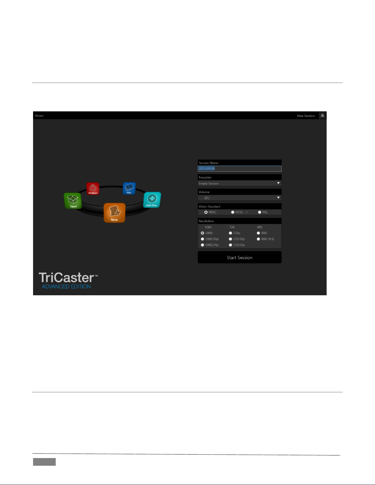
to simplify or automate complex workflows, design innovate outside-the-box solutions to creative problems,
or who just demand the very best of the best.
SECTION 2.4 STARTUP SCREEN
When you power up TriCaster the Startup Screen appears. This is your command center for initiating most
other operations.
FI GUR E 1
The Home page of the Startup Screen allows you to define and open sessions, essentially custom presets for
individual productions or other purposes. Later, when you re-open a session, all of its assets and settings
are remembered.
After creating a session (or opening an existing one), you are taken to the Session Page. Here you can launch
the Live Desktop (for live production), or perhaps choose to prepare Graphics (title pages), Manage content
(including importing and exporting media), or even create custom transitions.
SECTION 2.5 LIVE DESKTOP
TriCaster’s live production features are all available from its unique Live Desktop, which in many ways mimics
familiar production equipment. However, the Live Desktop provides far more functionality than similar
single-purpose devices, all in one integrated environment.
Page | 6
Page 19
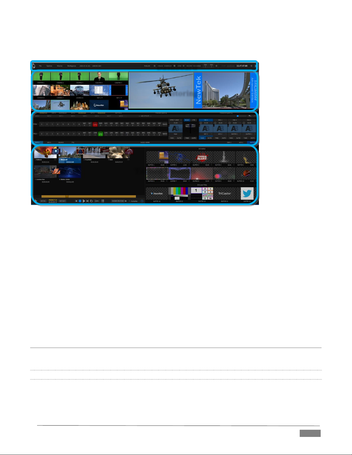
Monitoring
Dashboard
Live Control
Tabbed Modules
The various features, controls and modules comprising TriCaster’s Live Desktop are arranged in horizontal
bands, as seen in Figure 2.
FI GUR E 2
The top-most band contains TriCaster’s convenient and powerful Dashboard.
The area just below the Dashboard is *normally devoted to a multi-pane monitoring display,
providing source and output views.
* This area can be re-sized, and even completely hidden when outboard monitoring is in use; or
the display can be customized to complement the external Multiview or for numerous other
purposes.
The central Live Control section is home to the Switcher, Transition, DSKs (overlay channels) and
M/E controls (M/E panels can be minimized, and are hidden from view in Figure 2).
The bottom third of the Live Desktop holds tabbed control modules, including Media Players (DDRs
and Graphics players. plus a Sound player) and Buffers, PTZ camera controls and the Audio Mixer.
SECTION 2.6 FEATURES
Let’s take time for a brief overview of just some of TriCaster’s key features.
2.6.1 PHYSICAL
Rugged rack-mount chassis (TriCaster Mini is in a unique, durable yet extremely compact case).
Redundant power supplies (TriCaster 8000 and 860 only) ensure robust, reliable and quiet
performance in fixed or mobile installations.
Page | 7
Page 20

Massive storage capacity.
For 19” rack-mount models, all audio and video, monitoring and network connectors are easily
accessible from the rear for convenient installation in industry standard configurations.
Audio and video connectors are industry standard – XLR, ¼” TRS jack (both balanced) or BNC as
appropriate – ensuring broad compatibility and secure, locked connections. Headphone output uses
a standard 1/4” TRS stereo jack. Note that Mini uses
2.6.2 MULTI-TIER FAILSAFE
TriCaster’s ‘Always on Air’ features provide multi-tiered redundant failsafe mechanisms in both hardware
and software.
To name just a few:
Multiple software failsafe systems continually monitor and safeguard the live performance. Any
recoverable software error conditions are quickly and unobtrusively dealt with.
Video pass-through (not a TriCaster Mini feature) ensures that as long there is AC power, audio and
video from Input 8 (on 8-input models) or Input 4 (4-input models) are routed to Output 1 in a case
of catastrophic software condition.
If at all possible, streaming output and recording also continue even if all else fails.
TriCaster also has a comprehensive integrated system restore feature. Operators can quickly and
easily restore to factory defaults, or create a custom restore image on another drive and either
restore from that drive or use the backup drive to boot from if a complete hard drive failure ever
occurs.
Should a ‘less than ideal’ control surface USB connection fail, TriCaster will automatically restart it
without user intervention.
2.6.3 A/V INPUT AND OUTPUT
Live switch up to eight live video sources (8-input models).
TriCaster 460, 860 and 8000 support SDI and analog video input and output, plus internal and local
or remote network video sources. TriCaster 410 offers HD-SDI input and output without analog
support, while TriCaster Mini employs HDMI video input and output.
TriCaster 8000 only: connect popular video routers to greatly multiply input options.
Professional BNC video connectors provide increased durability and reliability for camera
connections. (TriCaster Mini includes strain relief provisions for HDMI cabling.)
Control supported robotic (PTZ) cameras via network or serial connection.
Freely mix 16:9 or 4:3 SD formats, and output HD sessions as HD and SD (4:3 or 16:9) simultaneously
from HD sessions.
Multiple Media Player modules allow you to insert pre-recorded video, music, sounds and imagery
into your live presentations.
Select Microsoft Windows® or Apple Macintosh® computers on the same network as Switcher
inputs for your live productions using NewTek's iVGA™ clients.
Assign one or both Network inputs on the Switcher to receive AirPlay
®
streams and switch live or
recorded content directly from your compatible Apple® mobile device or computer.
Update still Buffers in ‘watch folders’ from networked graphic workstations, even when these are
displayed live.
Page | 8
Page 21
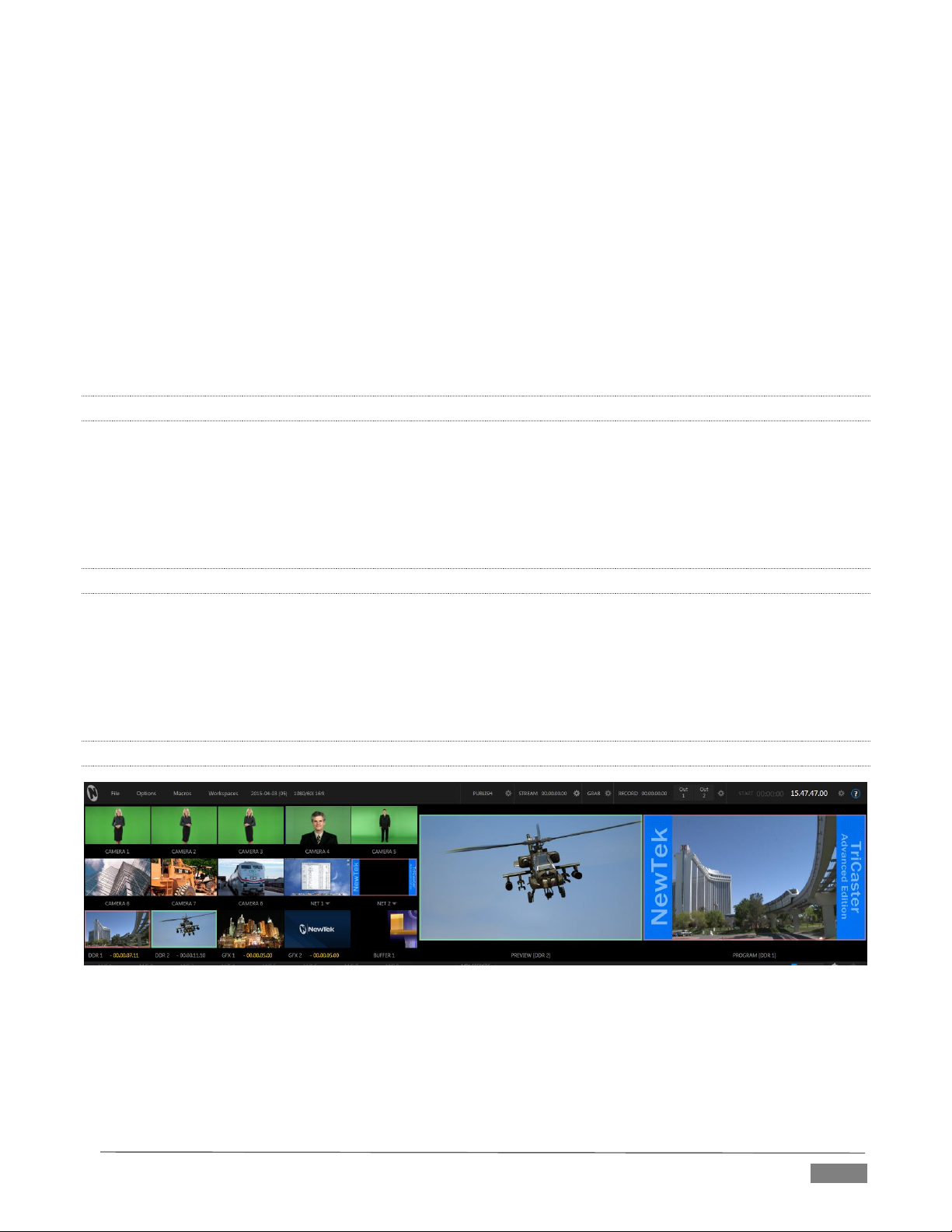
Transmit output to another TriCaster across the local network.
Create complex M/E effects and compositions using multiple sources and versatile virtual sets with
live (virtual) camera moves.
TriCaster 8000 (only) M/Es are reentrant, allowing you to cascade unbelievable effects in endless
creative ways
Use switcher row grouping to automatically harmonize video sources for multiple M/E s, etc.
Mix and route internal and external audio sources, including analog or SDI Embedded audio.
Multiple video outputs, including streaming and Network output can all supply independent feeds;
designate output mixes or individual sources at various resolutions up to 1920x1080 for output.
Two additional outputs referred to as Display ports.
Send main or custom audio mixes independently to any of the primary audio outputs, HDMI and the
Internet stream.
2.6.4 ALPHA CHANNEL I/O
Alternate video inputs can be configured as key channels for Fill + Alpha sources (not a TriCaster Mini
feature).
Network input sources, including third-party CG applications (etc.) support embedded alpha channel
(freeing up two video inputs).
Alpha channel (matte) output.
2.6.5 TIMECODE
External LTC timecode support (except TriCaster 410 and TriCaster Mini).
Default Quicktime® recording format includes full ‘per frame’ time-code.
IsoCorder™ recorded clips from multiple sources are easily aligned for synchronized post show
editing using embedded timecode (external timecode is not supported on TriCaster 410 or TriCaster
Mini).
2.6.6 MONITORING
FI GUR E 3
TriCaster’s Live Desktop includes a large monitoring pane with numerous multiple easily customized
Workspaces. By default, this area includes Program output and Look Ahead Preview monitors with
associated controls, along with all inputs.
Configurable desktop monitor array allows you to keep an eye on all live and internal video sources,
including Media Players and Network sources.
Page | 9
Page 22
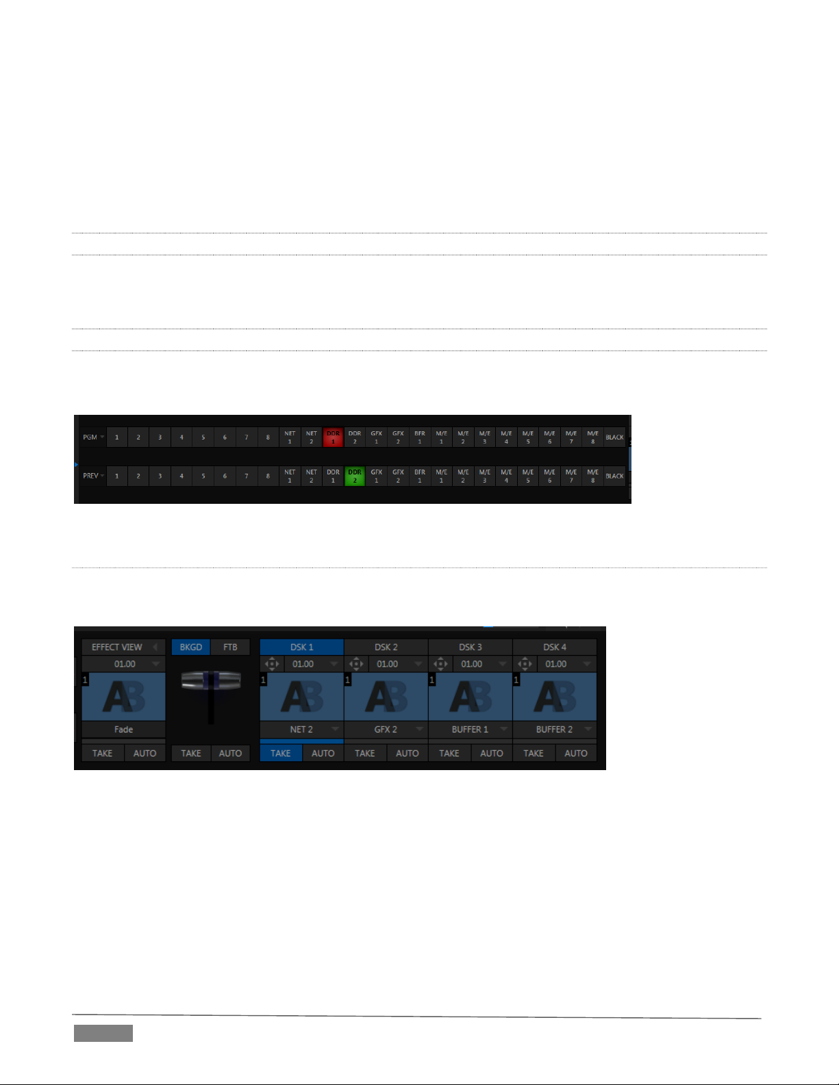
Waveform and Vectorscope monitors help you calibrate your signal to ensure your output meets
broadcast standards and looks great.
External Multiview Workspaces offer many alternatives, including numerous multi-bridge layouts,
overlays and Event Clocks.
Monitor sources on both Live Desktop and Multiview are user-configurable, and include Media Player
clip timecode counters, and custom logo display.
2.6.7 VIDEO PROCESSING
Full 4:4:4:4 32-bit floating point internal processing of all video sources.
Proc Amps and White Balance controls for every source preserve pristine image and color fidelity.
2.6.8 THE SWITCHER
TriCaster’s powerful 24-channel (8-input models)) or 15-channel switcher with native support for popular
professional video routers puts countless video sources at your fingertips.
FI GUR E 4
VI DEO LAY ERS AN D TRA NSI TIONS
The Transition section of TriCaster’s Live Desktop provides powerful tools for arranging and displaying the
numerous video and graphic layers contributing to TriCaster’s ultimate program output.
FI GUR E 5
Freely hot-punch or transition between external sources (Cameras or Network 1 or 2), internal
sources (Media Players) and M/E effects.
Latch selected Switcher and M/E source rows together in color groups to synchronize switching
operations.
TriCaster 8000 provides 4 DSK (Downstream Key) channels for the Switcher and four independent
Key channels for each M/E provide scores of creative possibilities. (Other models have two DSK and
one M/E Key channel).
Page | 10
Page 23
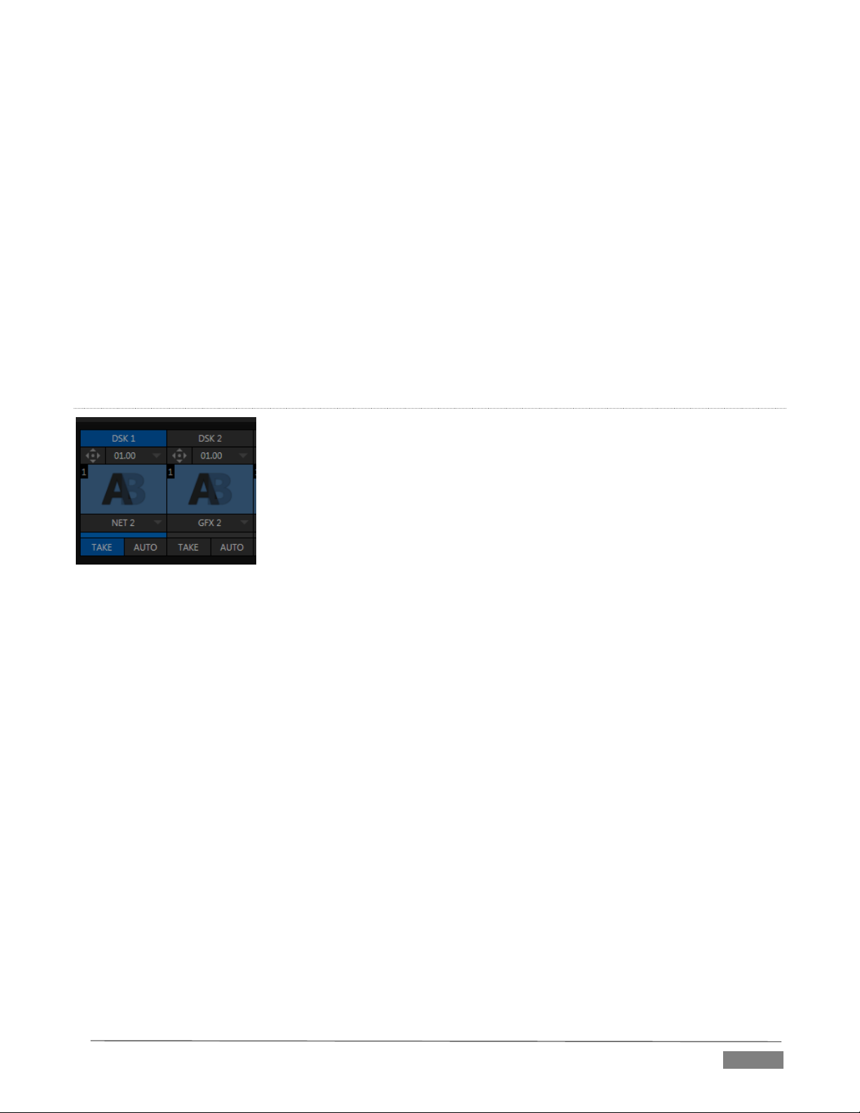
Use any of the hundreds of transitions supplied to reveal either Background or DSK/Key channels
with animated wipes, trajectories and dissolves, or select colorful and dynamic Animation Store
transitions with overlays, sound and TransWarp™ effects.
Create an unlimited number of custom transition effects with embedded sounds, dynamic cloth
effects, and full color overlays using the integrated Animation Store Creator application.
Create eye-popping animated graphics using your favorite software (such as Adobe After Effects®),
and convert them to colorful *animated Buffer effects that you can display on demand – without tying
up a Media Player. (*Not a TriCaster 410 or TriCaster Mini feature).
Reveal combinations of video layers with a single operation of the T-bar or single-click Take and Auto
buttons.
Local Transition controls for BKGD (Background) and DSK layers provide flexible, independent layout
and display of all layers and their transitions.
Select individual transition effects for every layer; adjust Transition Speed, Reverse and Ping Pong
options.
DSK CHAN NELS
FI GUR E 6
TriCaster’s DSK layers support downstream overlays (not to mention M/E Key channels, which can serve as
upstream overlays – that is ahead of the main Switcher). Some TriCaster models offer two DSKs, while
TriCaster 8000 has four.
Display DSK channels independently, and swap them during a switch with custom transitions for
each.
Use TriCaster’s numerous Media Players to overlay title pages, including scrolls, crawls and lower-
thirds, or assign a Camera feed or Network source to an overlay channel.
Alternatively, use the Buffer channels to assign a specific title, still image or animation effect to any
overlay channel.
Independent Crop, Position, 3D Rotation, and Scale controls for each DSK channel permit you (for
example) to configure multiple sources as ‘Picture in Picture’ elements, revealing them with
individual custom effects).
Page | 11
Page 24
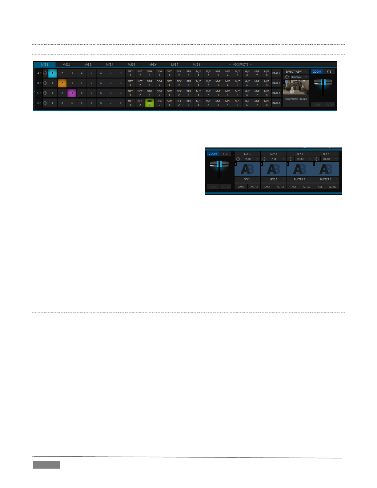
FI GUR E 8 (T RIC ASTER 80 00)
2.6.9 M/ES
FI GUR E 7 (T RIC ASTER 80 00 S HOW N )
TriCaster’s color-coded M/E (Mix/Effect) banks provide stunning effects.
These include secondary video mixing capabilities,
switching (with traditional wipes or Animation Store
transitions with TransWarp capabilities), full alpha
channel support and LiveMatte™ realtime keying
technology for green/blue screen effects, and jawdropping dynamic virtual sets, and much more.
Each M/E bank composition supports:
Multiple video sources (four for TriCaster 8000 only, or two).
One or more Key (overlay) channels, with individual transition capabilities.
Mix mode provides sub-mix functionality, with individual transitions for A/B Background layers and
Key channel(s).
Full keyers and discreet transition effects for every M/E channel.
Individual Scale, Position, Crop and Rotation controls for all channels
Buffer support in every channel.
TriCaster 8000 provides powerful realtime motion Tracker support as well.
Convenient MEM slots allow instant access to pre-configured M/E setups.
2.6.10 VIRTUAL SETS
Achieve the look of large, sophisticated studio sets in a very small space with NewTek’s astonishing
LiveSet™ virtual set technology.
Virtual sets support up to 4 keyable video sources (TriCaster 8000).
Zoom and pan the virtual ‘camera’ during live production (without touching the physical camera).
Or use a Holographic LiveSet to freely rotate and zoom the camera view.
Set up custom virtual set animation targets even while live.
2.6.11 RECORD AND STREAM
Record your live-switched production at full resolution to multi-platform, application friendly
QuickTime® formats, and more.
Optional capture formats include MPEG-2, AVI, and H.264 (m4v).
Quicktime and MPEG-2 files include embedded timecode (on supporting models).
Page | 12
Page 25
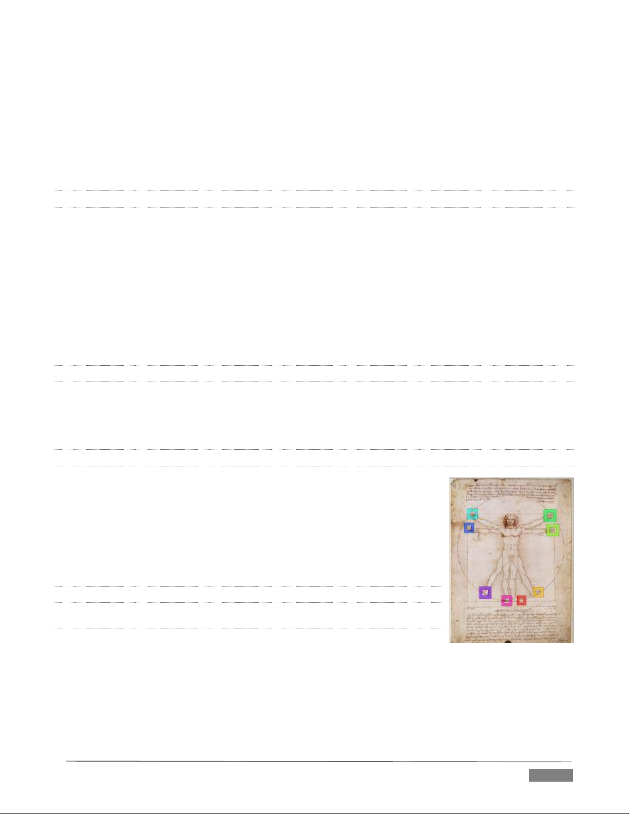
IsoCorder™ technology lets you record up to eight a/v sources (8-input models) at once, including all
camera inputs and both main outputs.
Grab still images from Output 1 or all inputs plus both main outputs at once.
Simultaneous output for broadcast, projector and live web stream to in-house and remote audiences.
Stream live to multiple Internet destinations for redistribution, and archive your stream locally.
Perform instant replays with custom transitions and playback speed with just one button press.
Or use NewTek’s TimeWarp™ instant replay control surface to mark, replay and manage highlights.
2.6.12 MEDIA PUBLISHING
Publish support makes it easy to distribute content to multiple targets in one pass. TriCaster stores
credentials for social media and upload sites, and provides a queue for uploading and file conversion.
Clips and stills from live sessions can easily be added to the Publish queue without interrupting production,
for distribution to multiple hosting services and social media sites (including Twitter®, Facebook®,
YouTube®, and more) all with a single click – even when live production recording is still underway.
This is great for concerts, galas, sport events, game shows and more. The Publish feature directly addresses
FTP sites and network locations too; transfer media to multiple locations at the same time to meet postproduction needs or other collaborative and archival requirements.
2.6.13 AUTOMATION
Record, edit, and play back macros, whether a simple operation or more involved series of events at the touch
of a button. Use powerful integrated automation systems to trigger these, simplifying complex tasks and
ensuring consistent operations.
2.6.14 HOTSPOTS, TRIGGERS AND TRACKERS
Define multiple onscreen Hotspots for different (chromakeyed) sources, and
trigger macros whenever something enters the hotspot. This live interactivity
opens up countless creative applications.
Trackers provide motion data from defined color regions as they move about in
the frame in realtime. Lock other video sources to Tracker output using Position
tools in M/Es banks and DSKs and they will follow obediently.
2.6.15 IMPORT
IM POR T MED IA
The integrated Import Media feature provides a convenient one-stop approach
to gathering productions assets.
Batch import media files for use in TriCaster’s Media Players.
Imported files are automatically categorized and sent to the correct locations, making them easy to
find and use during live productions.
Files are automatically transcoded to formats ensuring smooth playback when necessary.
Page | 13
Page 26
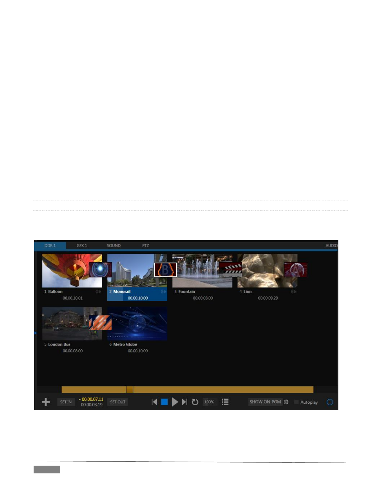
2.6.16 AUDIO MIXER
TriCaster provides extensive multi-channel audio control and management.
Adjust individual audio sources (internal and external) and introduce them into your program
manually or automatically.
Control output levels for program, headphones, auxiliary outputs, recording, and stream separately.
Convenient mixer MEM slots allow single-click access to prepared setups.
Powerful and flexible ‘audio follow video’ options.
Audio automation also allows ‘video follow audio’, and more, based on ‘threshold macros’.
Exclusive or latched Solo controls, including the ability to monitor audio captured by the IsoCorder™
module.
Independent 7-band EQ and compressor/limiter for each source and output, along with Noise Gate.
Multi-bus routing options.
Configurable VU meter calibration: Show VU meter calibration using digital (dBFS) or analog (dBVU
or dBu) scales (digital sources, SDI and AES/EBU, Streaming output and Record controls default to
dBFS).
2.6.17 INTEGRATED MEDIA PLAYERS
TriCaster’s numerous Media Players and title system serve up graphics, titles, video clips and audio files
quickly and easily during your live productions.
FI GUR E 9
Add a/v clips, sound files or still image files to Media Player playlists.
Trim and re-order playlist entries.
Page | 14
Page 27
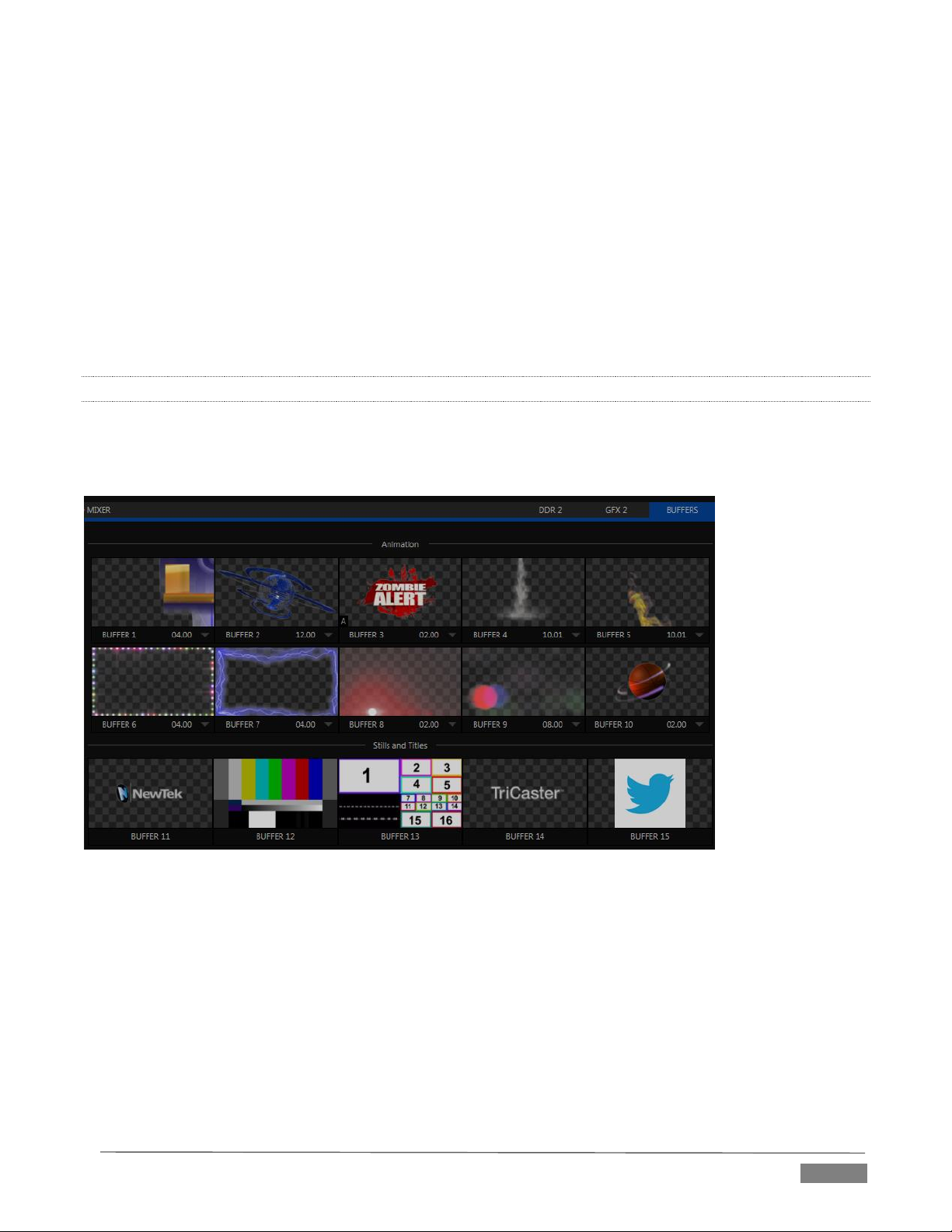
Add colorful transitions between clips.
Store playlists MEM slots for easy recall.
Flexible playback controls include variable Speed and Loop options.
Each Media Player has corresponding volume and other advanced audio controls in the Audio Mixer.
Convenient ‘per clip’ audio level and playback Speed control is provided.
Autoplay feature starts and stops playback automatically based on Switcher activity.
Control Media Players with macros triggered by other events.
Assign titles, graphics, clips or buffers to multiple DSK or M/E Key channels.
Edit titles live, even while ‘on air’.
The powerful Show button instantly transitions a selected clip to the Main Switcher or an M/E, plays
it, and then restores the target’s original source.
2.6.18 BUFFERS
The Buffers module provides quick review and management of TriCaster’s internal media buffer system, and
is in reality a combined multiview, player and asset management tool fully supported by TriCaster’s Macro
system.
FI GUR E 10 (TR ICA STER 8 000 SH OWN )
Buffers can be applied in any video channel, including all main Switcher and M/E rows, or as overlays in the
numerous DSK and Key channels. Buffer ‘slots’ can contain *animated effects (compiled from your own clips
using the supplied Animation Store Creator application), still graphics or title pages, all with full alpha
channel support (the number of buffer slots supporting animation varies by model).
Animated buffers (TriCaster 460, 860 and 8000) come in *two types, and either loop endlessly (perfect for
bugs, station IDs, etc.) or ‘auto-run’ once when displayed.
Buffer effects are resident in reserved Switcher Memory, making it possible to use them all at once without
tying up Media Players. Thus Buffers effectively substitute for many additional DDRs. In addition, each Buffer
slot has its own set of convenient presets.
Page | 15
Page 28

2.6.19 TITLES AND GRAPHICS
TriCaster includes an extensive set of live-editable title pages in various theme packs, all ready for immediate
use in your productions. Also part of TriCaster’s integrated software suite is LiveText™, NewTek’s
professional titling and graphics application. LiveText allows you to create your own great looking custom
title pages and motion graphics, including scrolls and crawls.
2.6.20 OPTIONAL CONTROL SURFACES
Most TriCaster bundles include a control surface designed as the perfect complement to your switcher,
making your live production operations even more convenient. Once you get your hands on one you’ll never
want to let go. Beyond this primary control surface, NewTek offers an optional instant replay control surface
called TimeWarp. Talk to your local reseller for a demonstration of this powerful add-on for your TriCaster.
In summary, TriCaster gives you the combined power of both a network control room and a complete post-
production facility in one simple to use broadcast appliance. Let’s jump in now. First, we’ll get you
connected; following that, we’ll explore TriCaster’s most important features.
Page | 16
Page 29
This chapter explains how to connect power, monitors and audio visual sources, and
external control devices to your NewTek TriCaster™ system. It also reviews the
registration process. After completing this short section, you’ll be all set to continue into
the Live Production Walkthrough chapter that follows it.
A word about UPS devices:
"pure sine wave" UPS. These units can
reliability.
SETTING U P
To begin, let’s review ‘what came in the box’:
NewTek TriCaster™
TriCaster 8000 only – package of three (3) 2TB hard drives
Keys to front panel of case (Rack-mount models)
Four attachable rubber feet (for desktop use)
A/C power cabling (external PSU with cable for TriCaster Mini)
BNC removal tool (to assist with cable connection and removal, rack-mount units only)
NewTek mouse and keyboard
Quick Start Guide
NewTek 3PLAY™ brochure
NewTek TriCaster registration reminder card
New product letter
SECTION 3.1 COMMAND AND CON TROL
Hint: TriCaster’s interface requires a monitor resolution setting of
at least 1600x1050.
1. Connect an external computer monitor to the port
labeled Interface on the backplate of 8-input models.
For 4-input rack-mount models, use the DVI connector
nearest to the Video In group for the interface monitor
connection. For TriCaster Mini, use either port in the
group labeled Interface/Multiview.
2. Connect the mouse and keyboard to USB ports on
TriCaster.
3. Connect the power cord (or cords, for 8-input models),
or – for TriCaster Mini – the external power supply
between the DC Power input connection on TriCaster’s
backplate and an external power receptacle.
4. Turn on the computer monitor.
5. Press the Power switch on TriCaster’s faceplate (located
behind the door on some models).
At this point, the blue Power LED will illuminate, and the adjacent
hard drive activity light should flicker as the device boots up. (If this does not
happen, check your connections and retry).
‘Modified sine wave’ UPS devices are
popular due to low manufacturing
costs. However, such units should
generally be viewed as being of low
quality and possibly inadequate to
fully protect the system from
abnormal power events..
For a modest added cost, consider a
be relied on to supply very clean
power, eliminating potential
problems, and are recommended for
applications demanding high
Page | 17
Page 30
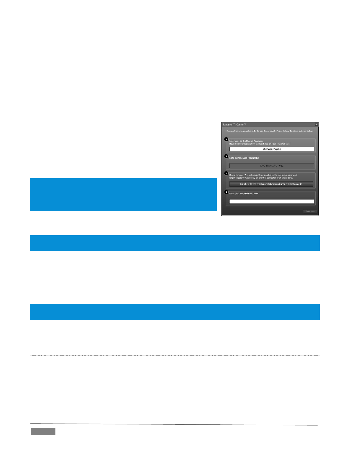
FI GUR E 11
Though not a requirement, we do strongly recommend that you connect TriCaster using an uninterruptable
power supply (UPS), as for any ‘mission critical’ system. Likewise, consider A/C “power conditioning”,
especially in situations where local power is unreliable or ‘noisy’.
Surge protection is especially important in some locales. Power conditioners can reduce wear on TriCaster’s
power supplies and other electronics, and provide a further measure of protection from surges, spikes,
lightning and high voltage.
SECTION 3.2 LICENSE AND REG ISTRATIO N
On launch, TriCaster presents an End User License Agreement dialog.
After you accept this, the Registration dialog shown in Figure 11 is
presented.
If necessary, enter the unique TriCaster Serial Number and Product ID
for your system. Important note: TriCaster’s video output displays a
watermark until the system is registered and unlocked.
Hint: If the Serial number doesn’t appear automatically, and you can’t find
it on your unit, you can obtain it from the registration webpage
mentioned in the next section, or by calling Customer Support Desk (open
seven days a week).
You can register and obtain your registration code directly from
TriCaster or other system connected to the Internet, or by telephone.
Hint: For later convenience, record the registration code for your TriCaster on the sticker provided for the purpose
inside the front access panel of the system.
3.2.1 ONLINE REGISTRATION
If you have connected your TriCaster to the Internet, simply click the button under Step 2 in the registration
dialog. This will take you to the Registration page (http://register.newtek.com) on NewTek’s website, where
you will find further directions.
Hint: More information on connecting TriCaster to a network can be found in Section 3.15 and Chapter 16, Network
Inputs.
Otherwise, you can visit the registration webpage from another system with Internet access. In either case,
after registering on the website, enter the resulting registration code into the field provided in the
Registration dialog.
3.2.2 REGISTERING BY TELEPHONE
NewTek’s Customer Support center can also handle registration requests by telephone, if that is more
convenient (when opportunity permits, you should still visit the website as discussed above to gain access
to software updates).
Page | 18
Page 31

Please have your Product ID (from the Registration dialog mentioned earlier) handy when you call. The phone
numbers for Customer Support follow:
Telephone:
(US) 1-800-862-7837
(Outside US) +1-210-370-8452
(Europe) +33 (0) 557-262-262
Hint: It’s a good idea to record the login name and password you choose when creating your website profile, and
keep them in a safe place. Jot down the registration code too; it could come in very handy if you ever need to
restore the TriCaster software to its as-shipped state when you don’t have access to the Internet.
UP DAT ES
It’s a great idea to check for recent free software updates for your system at this time, too – see the heading
System Utilities in Section 5.2.3 for more on this.
EN HAN CED SUPP ORT (PROTEK)
NewTek’s optional ProTekSM service programs offer renewable (and transferable) coverage and enhanced
support service features extending well beyond the standard warranty period.
Please see http://www.newtek.com/protek.html or your local authorized NewTek reseller for more details
regarding ProTek plan options.
SECTION 3.3 RACK MOUNTING T RICASTER
Several TriCaster models are designed for convenient mounting in standard 19” racks (mounting rails
designed for different TriCaster models are available separately from NewTek Sales).
Please keep in mind that adequate cooling is a very important requirement for virtually all electronic and
digital equipment, and this is true of TriCaster as well. We recommend allowing 1.5 to 2 inches of space on
all sides for cool (i.e., comfortable ‘room temperature’) air to circulate around the chassis.
Good ventilation at the front and rear panel is important, and 4-input rack-mount TriCasters in particular
require ventilated space above the unit (1RU minimum is recommended).
Hint: When operating TriCaster in a ‘road case’ for mobile production, it’s best to do so with both the front and
back covers (of the road case) removed.
When designing enclosures or mounting the unit, supplying good free air movement around the chassis as
discussed above should be viewed as a critical design consideration. This is especially true in fixed
installations where TriCaster will be installed inside furniture-style enclosures.
Hint: See also Appendix E, Dimensions and Mounting for helpful information for your TriCaster model.
Page | 19
Page 32
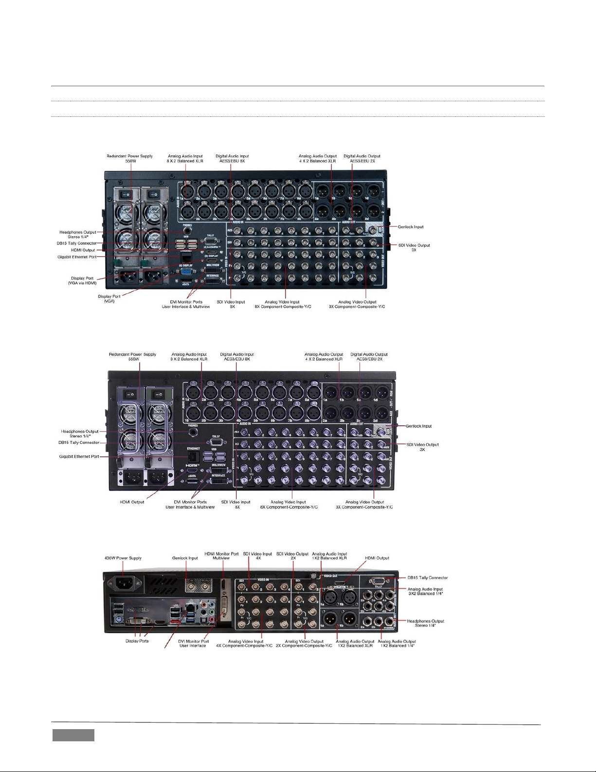
SECTION 3.4 INPUT CONNECTION S
3.4.1 CONNECT A/V SOURCES
External audio and video sources are connected to the appropriate inputs on TriCaster’s backplate.
FI GUR E 12 – T RIC A STE R 8 000
FI GUR E 13 - TR ICA STE R 860
FI GUR E 14 – T RIC A STE R 460
Page | 20
Page 33

FI GUR E 15 – T RIC A STE R 4 10
FI GUR E 16 – T RIC A STE R M INI
Note: Hardware details as depicted are subject to change without prior notice.
If your equipment supports SDI, this is the best quality option.
1. Connect sources to suitable connectors in the VIDEO IN section: SDI, HDMI (TriCaster Mini only),
Component, Y/C (S-Video), or Composite (may require RCA> BNC adapter).
a. SDI – Attach your SDI source connectors to one of the BNC connectors in the Video In group marked
SDI.
b. HDMI (TriCaster Mini only) – Connect your HDMI source cables to HDMI inputs on the front of the
unit.
Note: The analog video input connection options listed next are not provided by TriCaster 410 or Tricaster Mini.
c. Component – Attach the appropriate BNC connectors from your sources to all three analog
BNC connectors (labeled Y, Pb and Pr) in a column of the Video In group.
d. Y/C – If your S-Video equipment and cabling has the usual 4-pin mini-DIN connectors, you
will need an S-Video to dual BNC adapter.
Page | 21
Page 34

SDI Recommendations:
nevertheless have some limitations.
introduce added latency into the signal
path before TriCaster.
To connect Y/C sources, attach the Y (luma)
connector of your source to the second analog
BNC connector (labeled Pb). Attach the
source’s C (chroma) connector to the bottom
connector (labeled Pr).
e. Composite – Attach the composite source’s
connector (may require use of an RCA to BNC
adapter) to the connector in the input row
labeled Y).
Note: The broadcast video standard (such as NTSC, NTSC-J or PAL) of all
video sources connected for a given session must match.
2. To input analog audio along with the video, connect the
desired audio sources to the (XLR or ¼”) connectors as
provided in the Audio In group.
We’ll discuss audio Connection Type options a bit later,
in Section 3.12.
It’s worth mentioning here that SDI,
while ideal for many purposes, does
We do not recommend cable runs
exceeding 100 meters (for HD; or
double that for SD). Transmission
over greater distances may result in
signal losses, and call for measures to
boost levels, which may in turn
Note: SDI or HDMI video sources with embedded audio do not necessarily require separate analog audio connections.
With the appropriate software installed, TriCaster Advanced Edition systems can control and access output
from brands supporting the popular Grass Valley® Native Protocol are supported, as well as Black Magic
Design® Video Hub routers.
The implementation offers a number of configuration options; a basic setup would be as follows:
Connect the router to TriCaster by Ethernet cable, and then connect one (or more) of the router’s
video outputs to TriCaster inputs with matching numbers, using suitable video cables.
(For example, by default router output number 3 would be connected to TriCaster’s Input 3 for
control communication between the devices to be properly linked.)
Click the Shutdown icon on TriCaster’s Home page (Startup), and click the Administrator Mode at right.
In the Administrator Mode panel, click Exit to Windows.
Navigate to the C:\TriCaster\Configuration folder, and open the file named router_setup.xml by
double-clicking it (it will launch in Notepad).
3. 4.2 CONNECTING A VIDEO R OUTER
This file is where you add the routers you wish TriCaster to recognize. Each router is identified by an entry
you insert between the starting and closing “config” tags, as explained in the file comments.
A typical entry might be as follows:
<grassvalley ip="10.28.1.128" port="12345" name="AJA KUMO"/>
Page | 22
Page 35

Save the file after editing, and re-launch TriCaster.
Note: TriCaster communicates with each using individual IP address and port numbers, allowing multiple routers
to be connected simultaneously. Several TriCasters can even control either the same router(s) – especially useful
when TriCaster control is mirrored. File comments explain how you can bypass the default 1:1 mapping of router
outputs to TriCaster inputs when required, or prevent accidental changes to inputs that are displayed on Program
output, along with other extended configuration options.
Some routers allow each router input to be provided with a unique name. In such a case, TriCaster may be
able to access that name and use it for Switcher buttons as appropriate.
FI GUR E 17
To enable this behavior, checkmark the Use Router Name switch in the Properties panel (Figure 17) opened
by the Switcher (or M/E) button context menu item of the same name.
BL ACK MAG IC DESI GN® AUTO-DE TEC TIO N
For backwards compatibility reasons, these routers are auto-detected by default. (Black Magic® routers
may use a USB control connection, rather than a network connection. The router’s firmware should be up to
date. If detection fails, please contact BMD support for assistance.)
You can, if you wish, disable auto detection by editing the XML configuration file discussed above. (You might
do this to avail yourself of the extended configuration options that are provided by doing so.) To do this,
simply add the line below to the <config> section of the file.
<blackmagic_config discovery="false"/>
SECTION 3.5 GENLOCK CONNE CTION
(Not a TriCaster 410 or TriCaster Mini feature.) The Genlock input on TriCaster’s backplate is for connection
of a ‘house sync’ or reference signal (often a ‘black burst’ signal intended specifically for this purpose).
Many studios use this method to synchronize equipment in the video chain. Genlocking is commonplace in
higher-end production environments, and genlock connections are typically provided on professional gear.
If your equipment allows you to do so, you should genlock all cameras supplying TriCaster, and TriCaster
itself. To connect the genlock source TriCaster, supply the reference signal from the ‘house sync generator’
to TriCaster’s Genlock In connector. (See Section 3.13 regarding genlock configuration.)
Page | 23
Page 36

SECTION 3.6 TIMECODE CONNEC TION
(Not a TriCaster 410 or TriCaster Mini feature.) TriCaster supports external linear timecode (LTC) input.
Connect the cable from your timecode generator to one of the connectors in audio Input 7 (8-input models)
or Input 3 (4-input models). External timecode is enabled and configured in the Live Desktop (see Sections
Section 3.14 and 8.2.9).
SECTION 3.7 OUTPUT CONNEC TIONS
Next we’ll discuss the audio and video output connectors along with relevant settings. We’ll start with video
output – not only so you can view your results, but because certain items are best considered before
beginning a TriCaster session.
3.7.1 A/V OUTPUT
TriCaster provides multiple video and audio output connector groups, and very flexible options for display
of your live and recorded video streams. Here are some of the possibilities:
Simultaneously send output to standard and/or high definition devices from HD sessions.
Simultaneously send output to both analog and digital devices (except TriCaster 410, which provides
digital output connections only).
Send program output, a secondary mix, or custom ‘monitor bridge’ layouts to a supplemental monitor
or projector using Multiview.
Supply independent video outputs to the two Display ports for supplemental monitoring or projection.
Stream program output to the Internet via a suitable network connection.
3.7.2 HD AND SD
As mentioned earlier, for HD sessions TriCaster supports simultaneous output of both SD (Standard
Definition) and HD (High Definition) video. Except for TriCaster 410 and TriCaster Mini, the Video Output
connector groups on TriCaster’s backplate are arranged in vertical columns of four BNC connectors, offering
the following connection possibilities for live production:
Output 1 video output format is determined by the session (see Section 5.1). When the session is SD
4:3 or 16:9, output is likewise SD 4:3 or 16:9. When the session is HD, output is HD.
TriCaster Advanced Edition supports independent configuration of Output 2 (and Output 3 for 8-
input models). The desired format can be selected in the Live Desktop (Output Configuration panel).
1. Connect downstream video devices to the appropriate output connectors in the VIDEO OUT section,
whether SDI, HDMI, Component, Y/C (BNC) or Composite (TriCaster 410 supports SDI output only,
TriCaster Mini supports HDMI only).
Please note that Y/C and Composite may require RCA (cinch plug) or S-video (4 pin mini-DIN) to BNC
adapters, and also that both of these connection options support output at SD resolution only.
a. SDI or HDMI – Attach SDI connectors to BNC or HDMI (TriCaster Mini only) connectors in the
VIDEO OUT group labeled 1-(2 or 3).
Page | 24
Page 37

Hint: If your equipment supports SDI, this is the best alternative. Note that the following analog output options are
not supported by TriCaster 410 or TriCaster Mini
b. Component – Attach your device to the second, third and fourth BNC connectors (Y, Pb and Pr).
c. Y/C – If your S-Video equipment and cabling has the usual 4-pin mini-DIN connectors, you will
need an ‘S-Video to dual BNC’ adapter.
i. Attach the Y (luma) connector of your device to the second analog BNC connector row
(labeled Pb at far left in the VIDEO IN group).
ii. Attach the C (chroma) connector to the third analog connector (labeled Pr).
d. Composite – Attach the device’s connector to the first (top) analog connector (just above the pair
labeled Y/C).
2. Connect TriCaster’s audio outputs:
a. Analog audio – Connect external audio devices to the connectors in the AUDIO OUT section.
8-input TriCasters offer two pairs of four audio output connectors:
i. Connectors 1a-(1b or 1d) provide sound from the mix assigned to Output 1 (defaults to
Master in Output Configuration)
ii. Connectors 2a-(2b or 2d) provide sound from the mix assigned to Output 2 (defaults to Aux
in Output Configuration)
Note: These two output groups are actually treated by TriCaster as four independent stereo outputs, each
configured and controlled separately; see Chapter 15, Audio.
b. Digital audio – A separate digital audio connection is not necessary for SDI or HDMI output with
embedded audio. AES/EBU connectors are provided for Output 1(channels a-d) on 8-input
models.
Hint: TriCaster’s SDI and analog output sections can be used simultaneously. For example, you could use the
Composite output to view your program on a local composite monitor at the same time as you use the SDI
connection to supply broadcast equipment.
3.7.3 SUPPLEMENTAL VIDEO OUTPUTS
Additional dedicated video outputs make it possible to connect monitors or projection devices to TriCaster
for a variety of purposes including program output for IMAG (Image Magnification) installations or flexible
monitoring for the convenience of the operator.
1. TriCaster’s external Multiview output is supplied by a connector located near the main Interface
monitor connector (8-input models) or a neighboring HDMI port (4-input models). Again, connect a
suitable monitor or display device. The new device should be recognized and enabled by the system
automatically.
Page | 25
Page 38

Pin1 – LED1
Pin2 – LED2
Pin3 – LED3
Pin4 – LED4
Pin5 – LED5
(8-input only)
Pin6 – LED
(8-input only)
Pin7 – LED7
(8-input only)
Pin8 – LED8
(8-input only)
Pin9 – GND
Pin10 – GND
Pin11 – GPI1
Pin12 – GPI2
Pin13 – NC
Pin14 – 3.3V
(20 Ohms current limit)
Pin15 – NC
FI GUR E 18
The Multiview output offers a variety of optional monitoring layouts that can be selected at any time
in TriCaster’s Live Desktop.
2. Some TriCaster models also provide an additional, assignable video output on a labeled HDMI
connector. Simply connect a suitable external monitor or device to the connector on the backplane.
3. Stream and Network both require only a network connection.
4. Two special outputs are labeled Display (numbered [5] and [6] on 4RU TriCaster’s backplate). These
ports can serve projectors or similar large display systems, though of course they can be used for
other purposes too.
Note: A mismatch of output format and connection type is possible at times. For example, a Graphics player can
display imagery that does not correspond to the current output resolution or is not supported by the selected
connection type. TriCaster will attempt to display the output despite mismatches, but may not always succeed.
SECTION 3.8 TALLY LIGHTS
TriCaster’s Tally Light support allows you to connect external tally lights and similar devices.
These typically provide a red LED for the video input that is currently selected on the
Switcher’s Program row. (Not a TriCaster Mini feature.)
Note: Tally over SDI, as supported by devices from Blackmagic Design, is natively suported, and requires no special
configuration. Please see also: Section 22.9 regrading GPI support to trigger tally (and more); or search among
third party tally solutions listed at http://www.newtek.com/solutions/newtek-developer-network/all-partner-list.
3.8.1 CONNECTION DETAILS
Here is a pin-out listing for TriCaster’s HD15 Tally connector:
EN GIN EER ING N O TE S
Pins 1-(4 or 8) are ‘hot’ when the LED should be illuminated.
Each LED pin 1 (4 or 8) has a 200 ohm current limiting resistor inside TriCaster.
With no load (open circuit) the LED pins can reach 5V. With a typical LED load, they can be expected to
reach about 3V.
Page | 26
Page 39
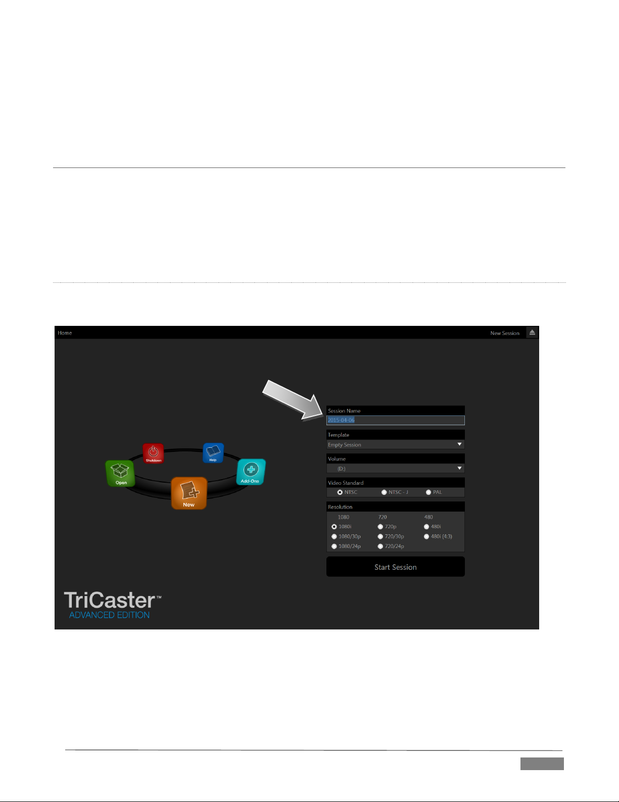
GPI stands for General Purpose Interface. Pins 11 and 12 are assigned for possible future use as GPI1 and
GPI2 connections, but support for GPI triggers has not been implemented in TriCaster at this time.)
To prevent damage to TriCaster’s components when making external connections to the tally light jacks,
care should be taken that connection to Pins designated GND (Ground) are always at ground potential.
SECTION 3.9 STARTING A SESSION
If TriCaster is not already running, power it up now to reveal the Startup Screen. (If TriCaster is already
running, and is in the Live Desktop or another area of the interface, you may need to click the small [x] button
at upper-right to exit, or click the Back arrow at upper-left in the Session Page to return to the Home Page.)
The Startup Screen consists of two similar pages – Home and Session. Among other things, the Home Page is
where you choose basic TriCaster session settings (see Section 5.1 for a discussion of sessions).
THE HOME PAGE
When no previously created sessions exist, the icon ring dominating the Home Page defaults to New, inviting
you to create a new session.
FI GUR E 19 (MU LTI - STA NDA RD TRI C AST ER S HOW N )
A link initially containing the text “Enter Session Name” is shown at the top of the right-hand pane when the
New icon is selected on the ring. Click in this area to modify the name using the keyboard if you like. (The
default name is the current date.)
Page | 27
Page 40
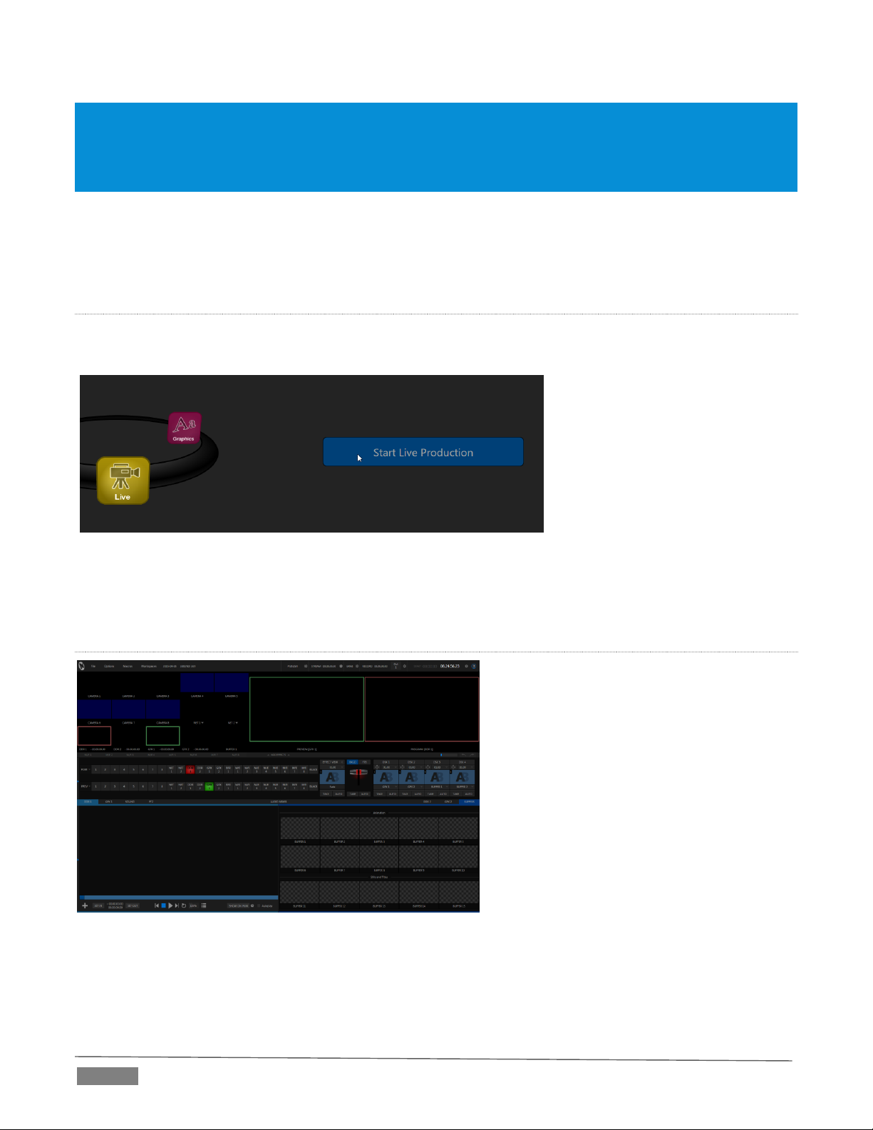
Note: TriCaster supports a variety of optional session configurations for live production. You can choose either HD
(High Definition) or SD (Standard Definition) operating modes.
SD options include both 4:3 and 16:9 (widescreen) image aspects. TriCaster Multi-standard models permit you to
select from different video standards according to your locale, choosing between NSTC, NTSC-J (Japan) or PAL.
Continue with session creation by designating the Video Standard used in your locale (Multi-standard models
only). For the moment, let’s choose 1080i for Resolution (even if the cameras you plan to connect are SD 4:3),
then click the Start Session link below. By default, new sessions are created on TriCaster’s D: (Media) drive
(see Section 5.2.1 for a discussion of session Volume options).
THE SESS ION PAGE
Clicking Start Session will take you to the Session Page. As our intention is to configure our connections (done
in TriCaster’s Live Desktop), click the Live button on the icon ring.
FI GUR E 2 0
Simply click the link labeled Start Live Production to launch the Live Desktop, which is likely where you will
spend most of your time working with TriCaster.
THE LI VE DESKTOP
Initially, as you have yet to configure input
devices or add content, the Live Desktop will
look a bit barren (Figure 21).
Take a quick look around, but then let’s
continue to configure your devices. (We had a
brief glimpse at the Live Desktop back in
Section 2.5, but we’ll examine it more closely
in Chapter 4, Basic – coming up soon.)
FI GUR E 21 (TR ICA STER 800 0 S H OWN)
Page | 28
Page 41

Let’s consider an example: An HD
1080i session offers the largest list of
optional output formats. The
controls allow you to select any of a
number of HD or SD formats.
Selecting an HD format sends the
source to TriCaster’s SDI and
Component output connectors
Selecting an SD format adds a
“Composite + Y/C” option to the
menu. Choosing this option sends
composite video output to the second
BNC connector in a given connector
row (Y), and Y/C to the third and
fourth BNC connectors (labeled Pb
As well, 16:9 or 4:3 screen aspect
alternatives are provided for SD
FI GUR E 22 (Tr iCa s ter 80 00 sho w n )
SECTION 3.10 CONFIGURE VI DEO OUTPUT
TriCaster provides complete video input
monitoring right on the Live Desktop. This allows
you to operate it without even connecting
downstream video monitors or devices. (You
might do just that in the case of productions
intended primarily for live streaming.)
Often, though, you will want to connect external
monitors or other downstream devices to the
VIDEO OUT connectors on TriCaster’s backplate
(see Section 3.6).
High definition video monitors should be
connected to either SDI or Component
connections.
For standard definition monitoring, several different connection types continue in service, including
Composite, Y/C (also known as ‘S-Video’) and – at the upper
end of the analog quality range – Component. (SDI provides a
digital output option, and is the only alternative offered by
TriCaster 410.)
To connect an analog standard definition monitor (not
supported by TriCaster 410), you must specify its connection
type in the Output Configuration panel.
Note that analog connections for LiveText™ output are pre-
defined (see Chapter 21 for details).
Let’s take a closer look at configuration options. Move your
mouse pointer over the large Program Output monitor on the
Live Desktop.
1. Click the Configure button (gear) that appears beside
the source label below the monitor pane to open the
Output Configuration panel.
This panel provides two tabbed panes, the first of which is
labeled Output. This is where the video signals present on
each of TriCaster’s video outputs, as well as the HDMI, Network
and Stream outputs and Display ports are configured.
There are various decisions to make for each output:
What video source do you want to assign to that
output?
What audio source will accompany it on connections
that carry both signals?
simultaneously.
and Pr).
output selections.
Page | 29
Page 42

FI GUR E 23 (8- I NPU T V E RS I ON SHO WN)
Optional Source selections for primary output channels include
any of the following:
Program output
A clean Program feed
The ‘look ahead’ Preview
The feed from any camera input
Either network input source
Media Player output
Direct output from any M/E
Selected Buffer content
Follow selected M/E Program or Preview, or a Switcher
color group.
Black
Which video format will be sent to the connectors?
For video outputs, which connection type will be used – SDI, Component, Y/C or Composite?
And so on …
3.10.1 OUTPUT CHANNEL OPTIONS
Let’s review Video source selection first. A drop-down menu by that name permits you to select sources for
TriCaster’s principal video output streams, referred to as Output 1 - (2 or 3, depending on the model).
TriCaster can send other streams to its outputs as well, as discussed shortly – but the primary out streams
are unique in certain respects.
Hint: Either (or both) of the a/v streams assigned to Outputs 1 and 2 are available for assignment to TriCaster’s
other outputs as well, by means of the Follow 1 and Follow 2 items in the respecitve source menus.
Audio menu options include the Master and Aux mixes, or the sound from any one of TriCaster’s audio inputs.
The video format (Resolution) for Output 1 always matches the current TriCaster session format, so its menu
is locked. For Output 2, though, the Resolution menu allows you to independently configure the format.
FI GUR E 24
Hint: Multiview, a versatile external display intended primarily for control room monitoring, is configured in
TriCaster’s Dashboard (click the Workspace menu).
It’s worth mentioning that, for TriCasters with analog outputs, SD formats offer different Analog Out options
than HD. HD is always presented on SDI and Component connectors, but in addition to these, Composite and
Y/C connections are still in common use for SD.
Page | 30
Page 43
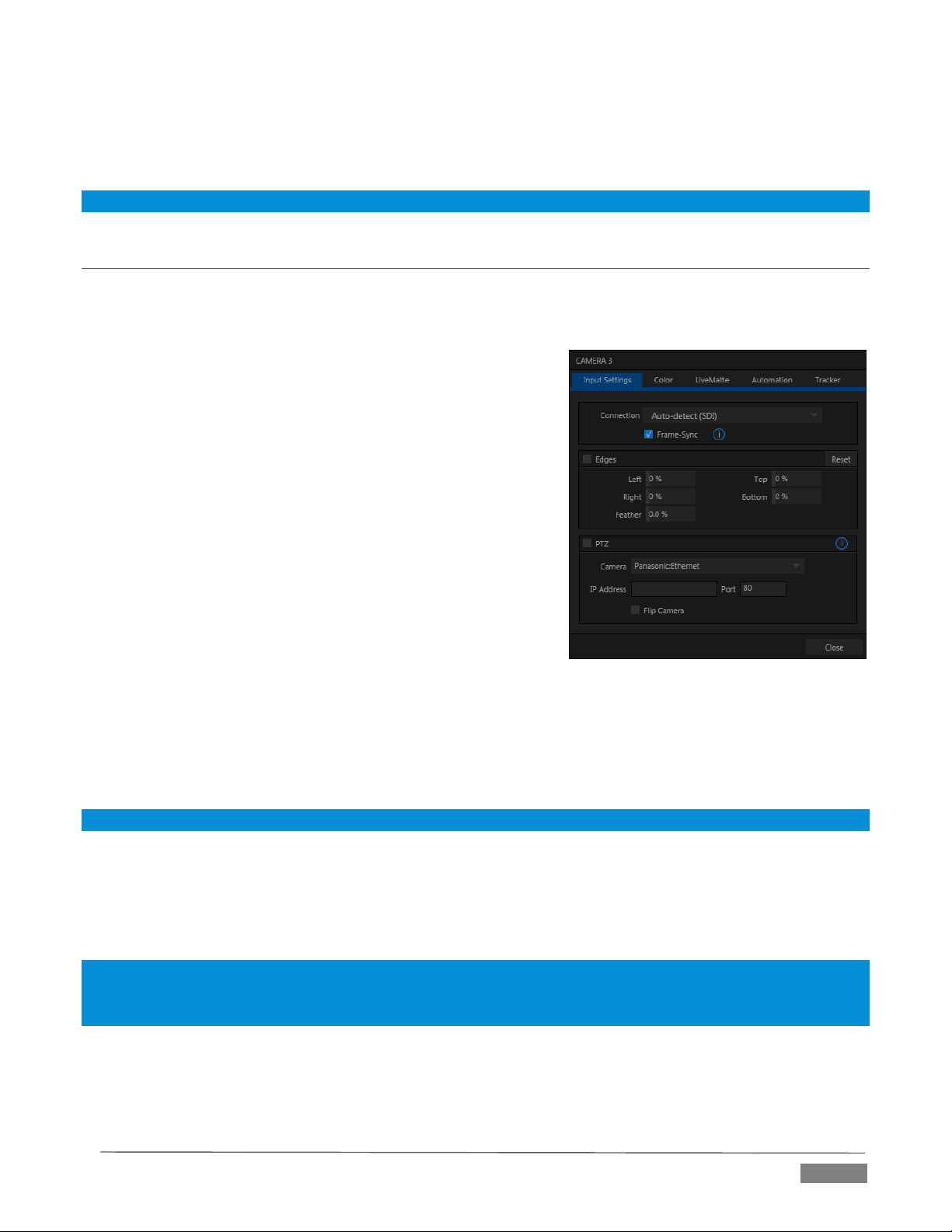
FI GUR E 25 (Tr iCa s ter 80 00 sho w n )
Composite and Y/C can even be used simultaneously, allowing three different devices to be connected to
outputs in one row for SD output formats – one digital (SDI) connection along with two analog connections
(see the example at right).
Note: See Section 8.1 for detailed information on all output options.
SECTION 3.11 CONFIGURE VIDEO INPUTS
Control over settings for video sources is provided in TriCaster’s monitoring section. The individual monitor
viewports on the Live Desktop can be flexibly assigned to show different video sources.
Complete monitor layouts can be prepared, stored and recalled
using tools located in the Workspace menu in the Dashboard.
We’ll look into that in depth in the Reference Section of this
manual, but for now let’s configure the video sources you
connected earlier (Section 3.4.1).
1. Click Workspace in the Dashboard (at the top of
TriCaster’s Live Desktop).
2. Four monitoring layout presets are listed at the top of the
menu as Interface A through D. Select Interface A, if it isn’t
already check-marked.
3. The monitoring pane will no show individual monitors
for each camera, with Camera 1 at upper left.
4. To continue, you could select Configure from the
monitor’s context menu, but let’s take a different approach.
5. Move your mouse back and forth over the Camera 1 monitor and notice that a Configure button (gear
icon) appears beneath it at right. Click this Configuration button to open a tabbed settings panel for
Camera 1 (Figure 25).
Hint: Alternatively, double-click the monitor to open this panel.
6. Click the Connection -down menu to see a list of various connection types. Select the correct format,
such as 720p (Component) or 1080i (SDI), for the video source you connected to Video Input 1 on
TriCaster’s backplate (menu alternatives vary by TriCaster model; for TriCaster 410, all connection
types are SDI).
Note: TriCaster Advanced Edition provides an Auto-detect (SDI) connection option. This will automatically
configure HD-SDI sources in an HD session, or SD-SDI sources in an SD session. However, mismatches between
source and session format require manual Connection type selection.
7. Close the Configuration panel for now (note that you can click the Close button or simply ‘click
outside’ the panel to close it).
Page | 31
Page 44

8. Continue to configure all connected external video sources in the same manner.
We’ll look at the other options and settings in the Configuration panel later (see Section 8.2), but at this point
you should be able to view the video inputs you have configured on their respective monitors.
3. 11.1 CONFIGURE A VIDEO ROU TER INPUT
Configure the input Connection to SDI, choosing the correct resolution for the device output as discussed
above, and then right-click on the Switcher row button for the TriCaster input where the router is connected
(see Section 3.4.2) to select which router input will be transmitted to TriCaster.
SECTION 3.12 CONFIGURE AUDIO
Click the Audio Mixer tab (centered in the lower third of the Live Desktop) to reveal audio features, including
configuration controls for all internal and external audio sources, IsoCorder™ recording levels and outputs,
including streaming.
FI GUR E 26 (8- I NPU T V ERS ION SHO WN)
Each input has its own small control panel, with Volume slider(s), VU meter(s), and other important features
conveniently located. At the top of each of these control panels is a label. Roll the mouse pointer over the
label to reveal a gear button at right which, when clicked, opens the Configuration panel (Figure 27) for the
input.
Page | 32
Page 45

FI GUR E 27
FI GUR E 28
A source Type selector drop-down at the top of the Configuration
panel (Figure 28) lists the Connection Type options available for the
corresponding input. Options may include Mic 1, 2 (with and without
phantom power), Line, AES/EBU, and SDI Embedded.
Note: TriCaster Mini omits this menu for inputs that support HDMI audio
only. Likewise, Phantom power is not supported by TriCaster Mini’s
analog audio inputs.
FI GUR E 29
This panel holds advanced audio features as well as basic setup controls. After you connect audio sources to
the input connectors (see also Section 3.4.1), the first thing to do is set the correct Connection Type using the
drop-down menu:
Select Mic 1, 2 for professional grade microphones or similar sources. On supporting models, use the
Phantom option for condenser type microphones requiring supplementary power.
Choose Line for most other device connections (including consumer devices such as a CD player,
computer audio output or VCR).
For 8-input models only, select AES/EBU for digital audio from an AES/EBU (AES3) output.
SDI Embedded or HDMI provide digital audio from the associated video connection.
Note: Analog audio levels conform to SMPTE RP-155. The maximum input/output level is +24 dBu, nominal Mic
input level +4 dBu (-20dBFS), and the sample rate is 96 kHz.
The Volume sliders (below the VU meters) default to their lowest settings on first launch. After adding audio
sources, slowly bring these sliders up to pass their signals through the system.
Hint: Most numeric controls in TriCaster can be reset to their defaults using Shift + double-click on the control knob.
The default value for Gain sliders is 0dBVU.
Some variation exists as respects signal levels from individual sources, even
within the same type. For Mic (and Mic + Phantom) connections, Gain (a.k.a.,
Trim) controls are provided to allow fine tuning of the input level.
To access these controls, open the Advanced Audio Configuration panel, by
clicking the Configuration button (gear) in the titlebar for an input control group.
Use the Gain knobs (Figure 29) to bring the levels for microphones and similar sources into a useful range
on the VU meter.
Page | 33
Page 46

AU DIO HE ADROO M
In digital audio systems, levels exceeding ‘legal’ values are ‘clipped’ (uniformly assigned the maximum value).
This results in audible issues that cannot be easily corrected later. For this reason, it’s customary to configure
normal operating level (also referred to as the ‘alignment level’, and sometimes, ‘nominal level’) well below
the clipping limit – sufficiently so that occasional excessively loud sounds (say, loud laughter or applause)
can be accommodated without risk.
This range above between nominal level and the highest possible level is commonly referred to as ‘audio
headroom’. What is considered a suitable headroom allowance can vary from one locale to another, in
different industry applications, and even in individual studios. TriCaster’s audio controls follow well-
established conventions, providing 20dB of headroom above nominal level (+4dBu at 0dB on the VU scale).
Hint: Confusion can sometimes arise because different calibration scales are common in various audio realms, and
even for different device types and software.
For example, analog mixers commonly show levels on VU scales indexed as just described. In contrast, digital
devices and editing software usually display levels in dBFS (Decibels Full Scale), with 0dBFS – the absolute maximum
allowable signal that can be recorded – at the top of the scale. TriCaster’s VU meters have selectable indexing,
allowing you to view a traditional dB VU scale or dBFS as you please (see Section 15.8.1).
Whatever scale you choose, use Volume controls (and, for Mic connections, the Gain controls in the
Configuration panel) to avoid over-modulation. TriCaster’s Compressor/Limiter feature (also located in the
Advanced Audio Configuration pane) is another powerful tool to help you prevent clipping – see Section 15.7.
SECTION 3.13 CONFIGURE GENLOCK
Genlocking is supported on TriCaster 460, 860 and 8000.
1. If the Live Desktop isn’t already open, launch a TriCaster session from Startup.
2. Access the Output Configuration panel by double-clicking the main Program Output monitor on the Live
Desktop.
3. Click the Genlock & Failsafe tab (Figure 30).
4. The default Reference Type in the Genlock settings group is SD (Bi-level), as this is currently the most
common reference signal type. However, if you supply an HD reference signal to the Genlock input, you
may want to change the setting to HD (Tri-level).
5. With the aid of downstream Waveform and Vector Scopes, adjust TriCaster’s Horizontal and Vertical
Position and Phase settings in the Genlock section of the I/O Configuration panel.
Page | 34
Page 47

FI GUR E 31
FI GUR E 30
Ideally both the cameras and TriCaster should be genlocked. If they are not genlocked to the same reference
signal as the TriCaster output, a TBC (Time Base Correction) operation is automatically applied. Time base
correction may drop or insert frames as necessary to maintain sync, hence is a less desirable approach.
Note: For a deeper discussion of genlocking, please see Section 8.1.2.
SECTION 3.14 CONFIGURE TIMEC ODE
TriCaster can use the system clock to generate ‘local timecode’ shown
in the Live Desktop titlebar, and also embedded in recorded Quicktime
(or MPEG2) clips.
To configure timecode, click the configure button (gear) located beside
the timecode display at right in the Dashboard. Please see Section 8.4.3
for more detail.
TriCaster 460, 860 and 8000 support external linear timecode (LTC),
which can serve in place of the local (system) time.
A switch is provided in the Timecode Configuration panel to enable this
feature, where supported.
SECTION 3.15 NETWORKING
TriCaster is capable of displaying screens from networked computers running NewTek’s iVGA Pro™ client
software, output from other supported applications (such as NewTek’s own LiveText™, or the growing
Page | 35
Page 48

number of third-party programs and systems), video streamed from additional TriCaster or 3Play™ systems
on the network, or from Apple AirPlay®.
Generally, simply connecting a suitable cable from the Ethernet port on TriCaster’s backplate to your external
network is all that is required to add TriCaster to a local area network (LAN). In some settings, additional
steps may be required. You can access the system Network and Sharing control panel to accomplish more
extensive configuration tasks – see Settings: Configure Network under the heading Administrator Mode in
Section 5.2.3. If further help connecting is required, please consult your system administrator.
The next section (Chapter 4, Basic Training) will introduce you to online tutorials, training materials and
other assets to guide you through your experience using TriCaster.
Page | 36
Page 49

This chapter provides a little information designed to guide you to other resources that
will introduce the major components and functions of your NewTek TriCaster™. This
includes extensive online training resources, friendly and helpful online communities,
and more.
In a very short time, these basics will be second nature to you. More detailed reference
material on all aspects of TriCaster follows in Part II (Reference).
BASIC TRAINING
Having made the essential external connections in the previous section, you’ll want to start your first
practical TriCaster™ session, and skim through some important fundamentals.
This would be the ideal time for us to introduce you to a special feature of your TriCaster™ - it has its very
own webpage.
SECTION 4.1 RESOURCES WEBP AGE
Having launched a session (refer to Section 3.9 if you need a refresher), those of you familiar with standard
TriCaster features will notice something new at upper-right in the Dashboard at the top of the Live Desktop.
FI GUR E 32
Click the (?) gadget shown there (Figure 32) to open a little panel that tells you how to navigate to your
TriCaster’s unique Resource webpage.
Simply connect any suitable device (be it a laptop, tablet, or desktop computer) to the same network
your TriCaster is on
Open the web browser on the device
And navigate to the URL shown in the dialog you opened by clicking (?)
Page | 37
Page 50
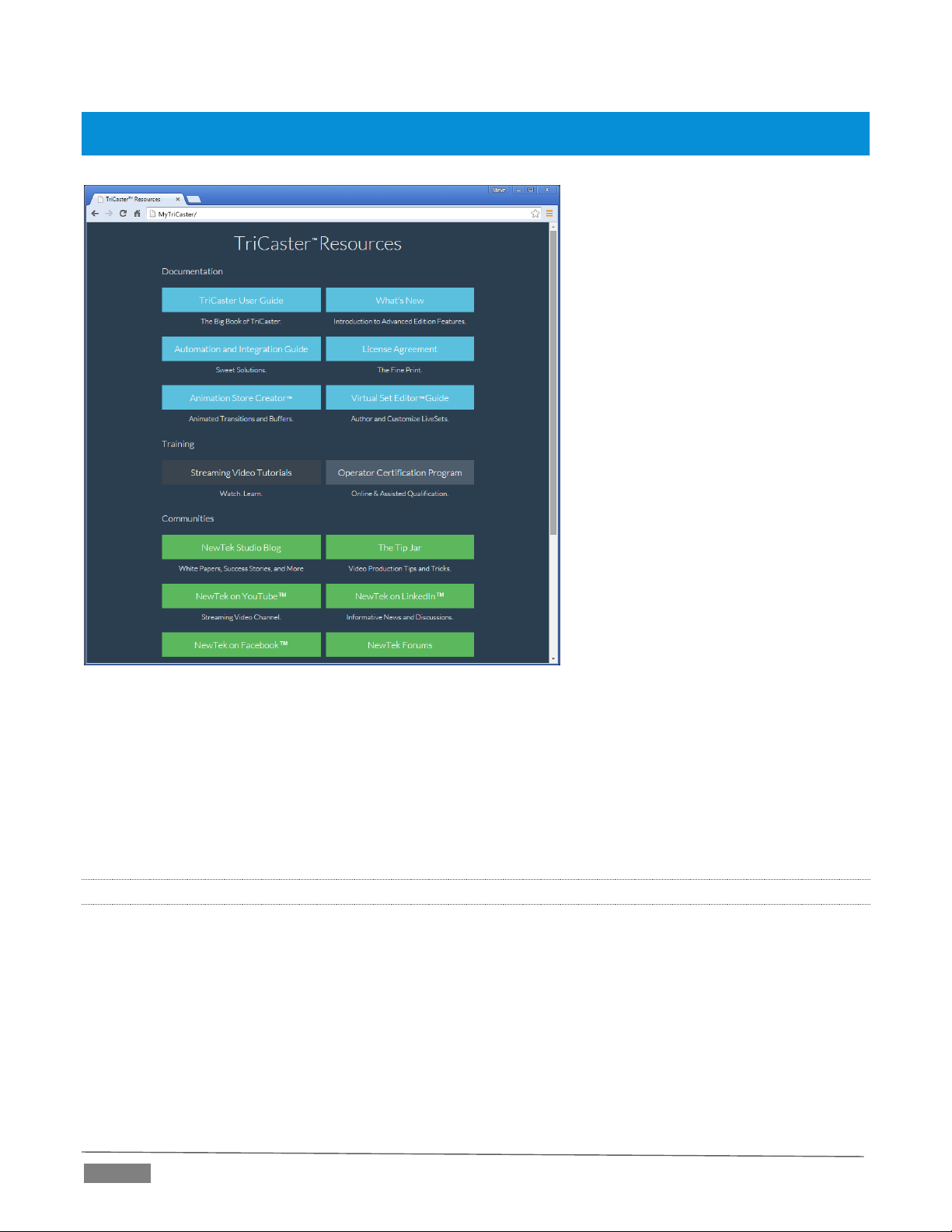
Hint: Access to the Resources webpage does not require an external Internet connection, though some of its links
will not work without one.
FI GUR E 33
The TriCaster Resources webpage is served directly from your TriCaster Advanced Edition system, and thus
is always available. Not only does this mean its content is always up to date and relevant to your installed
software, it also means that you can view it on a convenient mobile device alongside your TriCaster.
This allows you, for example, to use an iPad® or other mobile device to follow along with the steps outlined
in an online video tutorial, or look up the details of a TriCaster feature in the User Guide even during
production.
4.1.1 VALUABLE CONTENT
You’ll notice a number of different types of content grouped under the following headings on the TriCaster
Resources page:
Documentation
o What’s New – a brief overview of TriCaster Advanced Edition features
o TriCaster User Guide – the document you are reading (which tells you all about TriCaster)
o Automation and Integration Guide – provides a wealth of information pertaining to all aspects
of internal TriCaster (and 3Play™) macros and automation features, along with discussions
Page | 38
Page 51

of third-party solutions and topics related to integrating NewTek live production systems
into your studio pipeline.
o Animation Store Creator™ and Virtual Set Editor™ Guides
Training – online TriCaster video tutorials, and Operator Certification programs.
Extras - download updates, codecs and utilities, or install the DataLink™ for TriCaster web browser
extension (see Section 4.1).
Communities – forums, blogs, YouTube™ videos, Facebook
®
, and more …
Support – contact official Customer Service (including live chat), or read about product protection
programs.
SECTION 4.2 VIDEO TRAINING
NewTek is in the video production business, and it couldn’t seem more appropriate to us that we would
provide your introductory TriCaster lessons using that easy to understand and follow medium.
The link to online videos mentioned in the previous section takes you to a long list of TriCaster tutorials
designed for all users from novice to adept. From initial product registration to live production, streaming,
and publishing to social media services, to advanced topics such as M/Es, Tracking. Hotspots and automation,
you’ll find it all clearly illustrated and explained here.
It’s very likely that you will be able to easily grasp the basics of TriCaster production after viewing these
videos. When you need deeper knowledge, you will find Part II of this guide, the Reference section, takes you
there.
Hint: Generally, thanks to the considerable consistency across the TriCaster family of products, you will be able to
benefit from tutorials prepared using any TriCaster model.
SECTION 4.3 OPERATOR CERTIF ICATION
NewTek’s official Operator Certification program might interest you too, both as a way to obtain relevant
skills and knowledge as well as to assure potential clients that your attainments have been validated and
recognized.
Page | 39
Page 52

Page 53

PAR T II ( R E F E R E N C E )
A thorough examination of the various aspects of TriCaster: every button, menu item, feature and control is
considered in this section, so you can take full advantage of your system.
Page 54

Page 55
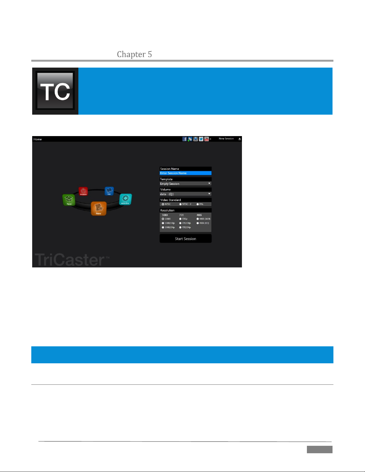
The TriCaster™ Startup Screen is the gateway to a suite of applications as well as
maintenance and management features for both sessions and the system.
We’ll discuss each of these in the pages that follow, beginning with a review of the concept
of sessions.
THE STARTUP SC REEN
The Startup Screen’s Home Page appears whenever you launch TriCaster™.
FI GUR E 34( MUL TI-S TAN DAR D M ODE L S HOW N )
From here, you create and launch sessions, then choose what sort of operations you wish to pursue within
the current session by making a selection from an icon ring on the Session Page. Your intention may be to
begin a new live production, or to produce another episode of a live series. Perhaps you wish to do prepare
some title pages for an upcoming event, or perform system maintenance.
We’ll look into each of these in turn, but first let’s consider that fundamental TriCaster concept, the session.
What is a session, and why are sessions both important and valuable to you?
Hint: Social Media accounts and other details related to TriCaster’s Share Media features are configured using
controls in the Startup screen’s titlebar. These matters are considered in Chapter 19, Publish.
SECTION 5.1 INTRODUCTION TO SESSIONS
Whenever you work with TriCaster, you provide certain information about the production environment:
What broadcast standard is used in your locale? Is it PAL, common in Europe among other places, or
perhaps NTSC, standard throughout North American regions?
Page | 43
Page 56

Finding your files – automatically.
Typical sessions include many media
clips, along with graphics, titles and
buffers. Naturally, users must ensure
make sure that all of media required is
To help with this task, TriCaster
automatically locates the necessary
media, even when drive settings have
been changed on the system (as, for
example, when a session backup has
been restored onto different drives
compared to the original setup).
If your task includes cameras or other live sources, are they HD, SD or a mixture of both?
How are cameras connected (are you using component or SDI connections, something else, or a
mixture of several connection types)?
As you continue, you may make other adjustments relevant to your current production requirements:
You might calibrate your cameras individually using the Proc Amp settings in the Input Configuration
panels.
If your production plans include the use of greenscreen staging, you will probably adjust the
LiveMatte settings for one or more cameras to provide optimal keying.
Perhaps you will use the output Proc Amps to adjust the display sent to a projection system.
What are your output device connection preferences?
o For example, will you send video to a local reference monitor using an S-Video or composite
cable?
o Do you intend to configure a connection for a projection system? What external audio
connections and adjustments are required?
You might create a playlist of custom title pages in a Media Player, along with additional playlists for
the DDRs.
During the course of the actual live production you may
perform further fine-tuning, and also add to the media content
used in the presentation:
You could grab a series of still images from Program
Output.
Grab some clips from the production for replay later.
And capture the network Stream output as a file.
The list of adjustments, activities and assets involved in a
specific production goes on, but the main point to grasp here is
that the session is comprised of all of the above collectively. If
you do not deliberately delete the session, all of your session
media and all of your session settings are ready for immediate
recall and re-use.
When you re-open an existing session, it’s just as if you were
continuing an earlier event. Thus, if you return to the same
venue another day under similar conditions, simply re-open your prior
session and you are virtually ready to go. (Of course, it’s the professional course
of wisdom to test everything before beginning any event.)
on hand for the session.
Naturally, you can store multiple sessions and re-open them freely. This greatly simplifies business models
that involve regular trips to specific remote sites or a number of unique episodic programs, and easily
accommodates different users with their own individual requirements and preferences.
Page | 44
Page 57

FI GUR E 35)
FI GUR E 36 (Mu lti- sta nda rd optio ns s ho wn)
SECTION 5.2 THE HOME PAGE
Having discussed sessions, let’s go on to consider how
sessions are created, and how you choose which one to
work on. These items, along with a few other top level
functions, are found in the TriCaster’s Home Page.
This primary screen is the first thing you encounter on
launching TriCaster. It is dominated by the icon ring
shown in Figure 35.
When you click an icon on the ring (such as New or
Open), that item advances to the front-most position.
Hint: Alternatively, you can use the keyboard’s left and right arrow keys to cycle through the icons on the ring.
Choosing an icon from the ring also updates the right-hand pane of the Home Page to provide options and
controls related to your choice.
For example, the first thing you will likely do on launching a new TriCaster is create a session. In anticipation
of that, the New icon is automatically pre-selected whenever no sessions already exist on TriCaster. This
results in the relevant session options being displayed at right, as shown in Figure 36 (Multi-standard
TriCaster options shown).
5.2.1 NEW (SESSION)
As just mentioned, clicking New on the icon ring populates the pane
at right with related options.
Principally, for each session you must designate (by selecting
switches) your local video standard
Multi-standard model only – select NTSC, PAL or NTSC-J
Session format – 1080i, 1080/24p, 1080/30p, 720p,
720/30p, 720/24p, 480/30i (16:9) or 480/30i (4:3).
Multi-standard models offer PAL format equivalents.
SE SSI ON NAME
You will see a name field for your session listed above the options
pane at right (Figure 37). You can click in this field to modify the
default name (the current date) using the keyboard.
Page | 45
Page 58
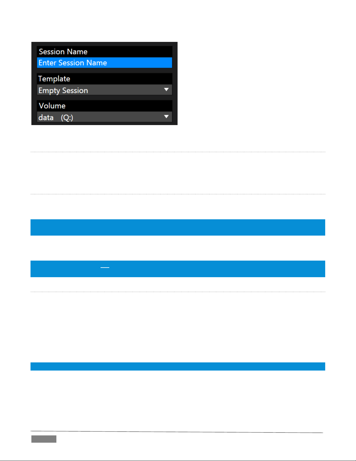
FI GUR E 37
TE MPL ATE
The Template drop-down menu (Figure 37) lists all sessions currently available on the system. If you select
an entry, the session you create subsequently retains all settings of the source session, but without content
from its Media Player playlists.
VO LUM E
A control labeled Volume appears just beneath the Session name. This assigns the hard drive the session (and
its associated content) will be created and stored on.
Note: When using TriCaster’s IsoCorder™ feature to record multiple sources, you will likely assign more than one
hard drive to capture duties. Session keep track of recorded clips too, providing easy access to them for live use.
Suitable hard drives inserted in removable drive bays on selected TriCaster models are listed in a drop-down
menu when you click on the Volume control. You can select any drive shown as the session drive.
Note: External drives are not recommended for active use as session drives. See Section A.1.8 for hard drive
recommendations for use in TriCaster’s removable drive bays.
FO RMA T AND OUTPU T CO NSI DER ATIONS
Remember that for live production, TriCaster can simultaneously supply both SD and HD output for either
SD or HD sessions. During an HD session, for example, you can output either (or both) HD or SD video, and
SD video output can be either in a 16:9 widescreen format or cropped for display on a 4:3 television (see
Section 8.1).
The session setting has some other significant ramifications, too. For example, if your session format is SD
4:3, this is the file format captured by the Record function when capturing Program output … even when the
video cameras supplying your inputs are HD; the opposite is also true.
Note: See Section 8.1 for more information on Video Output configurations.
Having made your selections, you would normally click the Start Session button at lower right to launch
TriCaster’s Live Desktop – but first, let’s explore a few other features of the Home Page.
Page | 46
Page 59
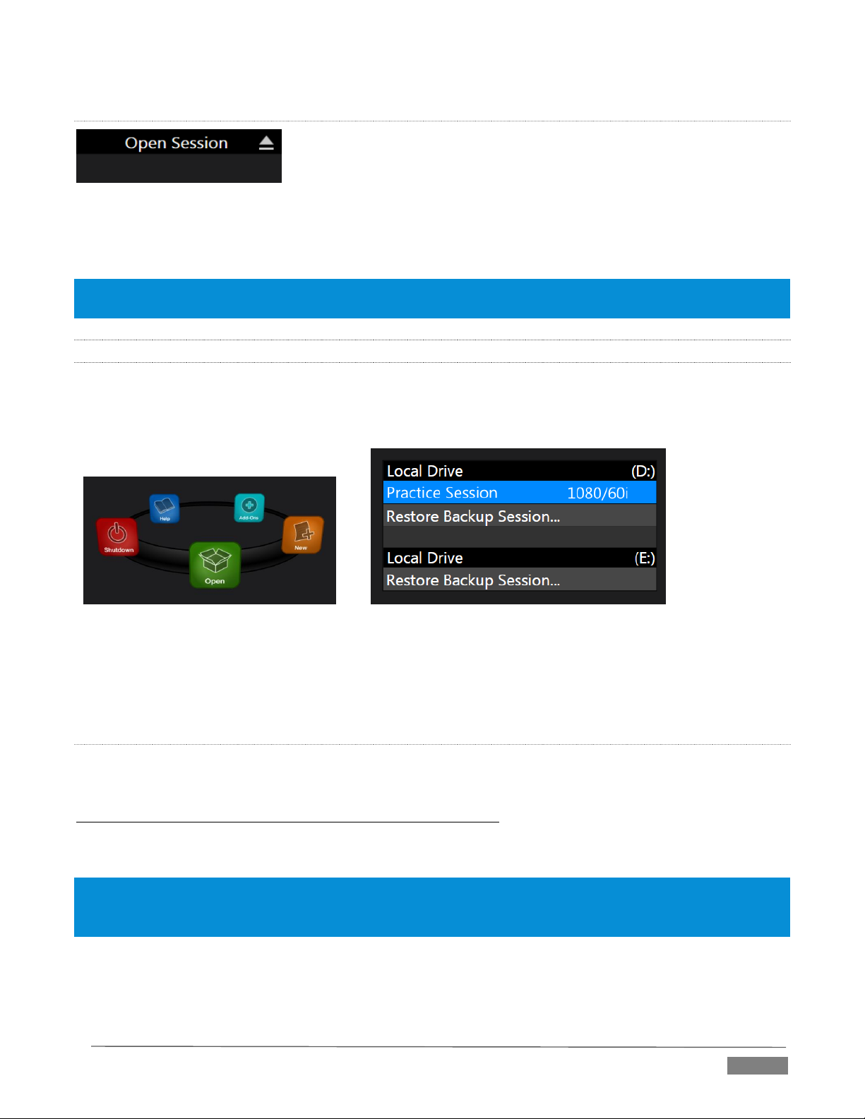
FI GUR E 39
FI GUR E 40
EJ ECT
FI GUR E 38
An Eject button at the top right corner of the page allows you to safely disconnect external drives. (Drives
can also be ejected from the Live Desktop.)
Note: Media configured as Read Only is not shown for the New or Open (session) features, since they cannot be
used for sessions. However, Read Only media can be used for import purposes.
5.2.2 OPEN (SESSION)
If there are existing sessions on TriCaster, the icon ring on the Home Page will default to Open (Figure 39).
Clicking Open causes the Sessions List to appear at right. This pane lists all sessions stored on qualified media
currently mounted on TriCaster.
Available sessions are grouped under the names of the storage volume they are located on (Figure 40). The
listing shows the Session Name and Format for each session. Let’s look at the Sessions List briefly before we
open a session.
CO NTE XT ME NU
Right-click a session name to open a context menu with two items listed in it: Rename and Delete. Be aware
that the Delete function should be used thoughtfully, as it cannot be undone.
All content stored in the named session’s folders will be deleted, including clips, images and titles, and even
LiveText title project files created within the session (unless you have deliberately saved the projects and
related files to locations outside the session folders).
Note: Content that is not local to the session but which was used in it is not deleted. For example, you may have
added still images to your playlist directly from a USB thumb-drive, doing so without actually importing the files
into the session. Those external files will not be deleted.
Page | 47
Page 60

RE STO RE SE SSION BAC KUP
In another section of the Startup Screen (Session Page>Manage) there is a feature that allows you to back up
the current session to another storage volume.
The Restore Session Backup link at the bottom of the Session List (for each drive) is provided to compliment
this feature. To restore a session you have previously archived, click Restore Session Backup (Figure 41), and
use the file explorer provided to select a .SessionBackup file.
FI GUR E 41
Click Open, and a progress gauge will track the restoration process. In due course, the newly restored session
will be added to the Session List for the specified drive.
Hint: Restoring a session that has a lot of content can take considerable time. Be judicious, then, if considering a
restoration shortly before a scheduled live production.
OPENI NG A SE SSI ON
Just as you were able to select an icon on the ring using the left and right arrow keys, you can highlight a
name in the Session List using the Up and Down arrow keys; then press the Enter key to open it (or simply
click the name of a session to open it immediately). Selecting a session takes you away from the Home Page
to the Sessions Screen.
5.2.3 SHUTDOWN
This selection provides Restart TriCaster, Shutdown TriCaster, and Administrator Mode links. The first two
options are presumably self-explanatory, but the latter deserves a bit more discussion.
AD MIN ISTRATOR M O DE
Selecting Administrator Mode from the Shutdown menu on the Home Page icon ring exits TriCaster’s live
production environment, and takes you to a new screen (Figure 42) that offers various functions and settings
having to do with TriCaster system maintenance and management.
FI GUR E 42
Page | 48
Page 61

Administrator Mode options are grouped under several headings, as discussed next.
BR OWS E
Web – Opens the default system Internet browser.
Files on Disk – Opens a system file window.
SYST EM UTI LITIE S
Register TriCaster – TriCaster shows a watermark on output before registration, so we encourage you
to register early.
Among other reasons, doing so will serve to identify the unit to NewTek as yours in case of theft, and
will also allow you to check for software updates that may have been recently released. (The steps
in the registration process were outlined back in Section 3.2, so we won’t repeat them here.)
Update TriCaster – NewTek may periodically provide software updates for your TriCaster. Updates
can enhance performance, security or even add useful new features.
If TriCaster is connected to the Internet, clicking Update TriCaster will automatically check for a more
recent software version and offer to install it. This way you can be sure the very latest *release
version of the software for your TriCaster is installed.
Alternatively, you can go to the NewTek web site, click My Account, and use the login details you
provided when registering your TriCaster to access your personal product page. Click the “my
downloads” link at the top of the page, and check the list shown.
If you find an update, you can install it manually as follows:
1. Locate a suitable update in “downloads” and click on it.
2. At the dialog popup, choose Run.
3. Comply with any onscreen prompts that follow.
* Advance software releases are also sometime posted on the ‘downloads’ page for manual
download and installation. These versions, listed as “Latest” on the web page, will be newer
than those provided by automatic update and (although not yet approved for final release)
might be well worth trying if you encounter an issue.
Hint: If you wish, you can instead access the same webpage from a second computer connected to the Internet,
then transfer update files to TriCaster using a network connection or perhaps a USB thumb-drive. Because updates
are often quite large, it is best not to download these to a mobile device.
Defragment all Drives
Over the course of lengthy use, data on hard drives devoted to audio and video storage tends to
become fragmented, which degrades playback performance. Defragmenting will correct this
condition.
Page | 49
Page 62

FI GUR E 43
You could think of your hard drive as being like a shelf in your library. As time goes along, the shelf
fills with books. Some are quite large, others smaller – just as TriCaster media files may be larger
smaller.
As time goes along, you decide to remove books you have
finished using from the shelf, in order to make room for new
additions. You remove a book here, another there, opening up
gaps between the remaining books.
This makes some shelf space available by creating gaps
between the remaining books. Sadly, another large new book
may be too big to fit in any one of the gaps.
A foolish librarian might tear the new book into smaller
sections, just big enough to fit into the open spaces on the shelf.
This would obviously be unwise. When you wish to refer to the
book later, you will waste a lot of time locating and assembling its sections before you can access it.
How much better it would be to slide the remaining books closer together, combining all the free
space first. Unfortunately, computers are ‘foolish librarians’. They tend to want to fill in all the gaps
in their storage areas, even if this requires literally shredding your ‘book’ (in reality large video files
from your TriCaster sessions) into tiny fragments.
Defragmenting the storage volume has the same effect as sliding the books together, resulting in one
or more larger gaps. The end result is that TriCaster doesn’t have to frantically search in many
different places to assemble the video streams from your recorded session.
Hint: Defragmentation can sometimes take considerable time, so it’s not something you want to begin just before
an important event.
Backup or Restore System – A complete set of Backup and Restore features are available to help in the
event of an unforeseen problem.
We strongly encourage you to protect against any unforeseen occurrence by using the Backup feature
soon after registering TriCaster. Please refer to Section A.5.7 in Appendix Chapter 22 for details.
Command Window – Open a system command line window, allowing you (among other things) to use
advanced commands to manage your system and network settings.
Swap Primary Monitor – reverse the monitor assignments currently in use for TriCaster’s interface
and Multiview displays.
SE TTI NGS
Regions and Language – Open the system language control panel.
Advanced Keyboard – Open the system keyboard controls panel.
Date and time – Open the system keyboard controls panel.
Page | 50
Page 63

The primary User Guide and Control Surface
manuals are found here, as well as documentation
for other TriCaster features, such as the LiveText™
manual.
Click the License Agreement link to review the
TriCaster license requirements, or the About
TriCaster link to list software version information,
credits and acknowledgments.
FI GUR E 44
Configure Network – Open the system network controls panel.
Display – Open the system display controls panel (useful for configuring multiple monitors, among
other things).
Fonts –Open the system font management console, allowing you to add that new font your client
wants you to use for their title pages.
System Name – It can be very useful to modify the default name your TriCaster is identified on the
network. This is especially true when more than one TriCaster might be on the same network. The
System Name feature opens the System Properties console’s Computer Name tab. Click the Change
button to modify the current name.
SHUT DOWN
Exit to Windows – Leave the Administration Mode screen and display the standard system desktop.
Back to TriCaster – Exit Administration Mode, and return to TriCaster’s Startup screen and the
production environment.
5.2.4 HELP
Select the Help icon to reveal links to open TriCaster manuals and other information.
5.2.5 ADD-ONS
NewTek offers additional software tools to expand the power of your TriCaster. The icon labeled Add-Ons
on the Home Page provides access to some of these tools.
FI GUR E 45
Page | 51
Page 64
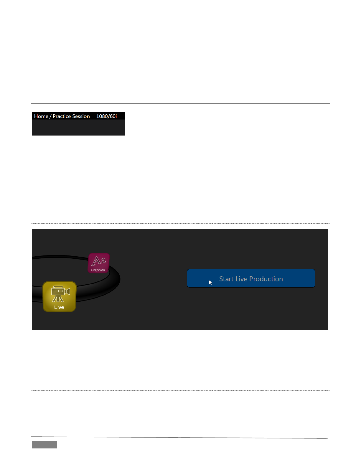
FI GUR E 46
When you select the Add-Ons icon, links are displayed at right for installed software applications, allowing
you to launch them. For example, Figure 45 shows links to the included Animation Store Creator utility as
well as a demo version of the optional Virtual Set Editor™ program and the very useful DataLink Configuration
applet (see also Section 5.3.3; please refer to the accompanying Automation and Integration Guide for full
details on DataLink’s many powerful source options).
SECTION 5.3 THE SESSION PA GE
Opening a session from the Home Page (whether using Open or New)
takes you to the Session Page, providing a new set of selections on the
icon ring.
The name of the current session is shown in the top-left corner of the screen. The current session is displayed
in the form “Home/session name”.
If you wish to leave the current session and return to the Home Page, you can click the large Back Arrow
displayed beneath the session name, or the word “Home” in the session name label.
Initially, the icon ring in the Session Page offers three selections. These are discussed next.
5.3.1 LIVE
FI GUR E 47
The icon labeled Live represents the Live Desktop, TriCaster’s live production center. Selecting it (by clicking
the icon or using the left/right arrow keys to bring it to the front), presents a Start Live Production link in the
Session Page’s right-hand pane; click this link to launch the Live Desktop.
5.3.2 GRAPHICS
TriCaster includes an integrated variant of LiveText™, NewTek’s standalone titling and CG application.
Page | 52
Page 65

FI GUR E 48
Selecting the Graphics icon displays a number of related items on the right-hand side of the Session Page.
FI GUR E 49
When you first enter a new session, no LiveText projects are listed in the area under Project Name. After you
create one or more projects, the name(s) will appear here and, as you would expect, you can re-open the
project by clicking its name.
Note: TriCaster stores new LiveText projects inside a folder named for the current session, as follows (for example):
D:\LIVETEXT PROJECTS\sessionname\projectname.cg.
LiveText’s internal File menu and Save As functions default to the same location. However, it is possible to
use File>Save As to store a project in another location outside the session structure.
Be aware that projects stored outside the session structure are not shown in the project list on the Sessions
Page. To re-open them, you’ll need to navigate to the project file using File>Open in LiveText.
Note: Similarly, external projects will not be backed up by the Backup Session function (or be deleted by the Delete
Session function)
To create a new LiveText project, click in the default project name field (just above the Start New Project link)
and modify it, then click Start New Project. When you finish working in LiveText, click the [x] button in its
upper-right corner (or select Exit in the File menu) to return to the Session Page.
Note: The integrated version of LiveText cannot be accessed during live production operation. It is provided as a
title page and graphics authoring tool only, not a CG server. A number of excellent third-party offerings, as well as
the standalone version of LiveText (available from NewTek as a separate purchase) are listed and described in the
accompanying Automation and Integration Guide.
Page | 53
Page 66
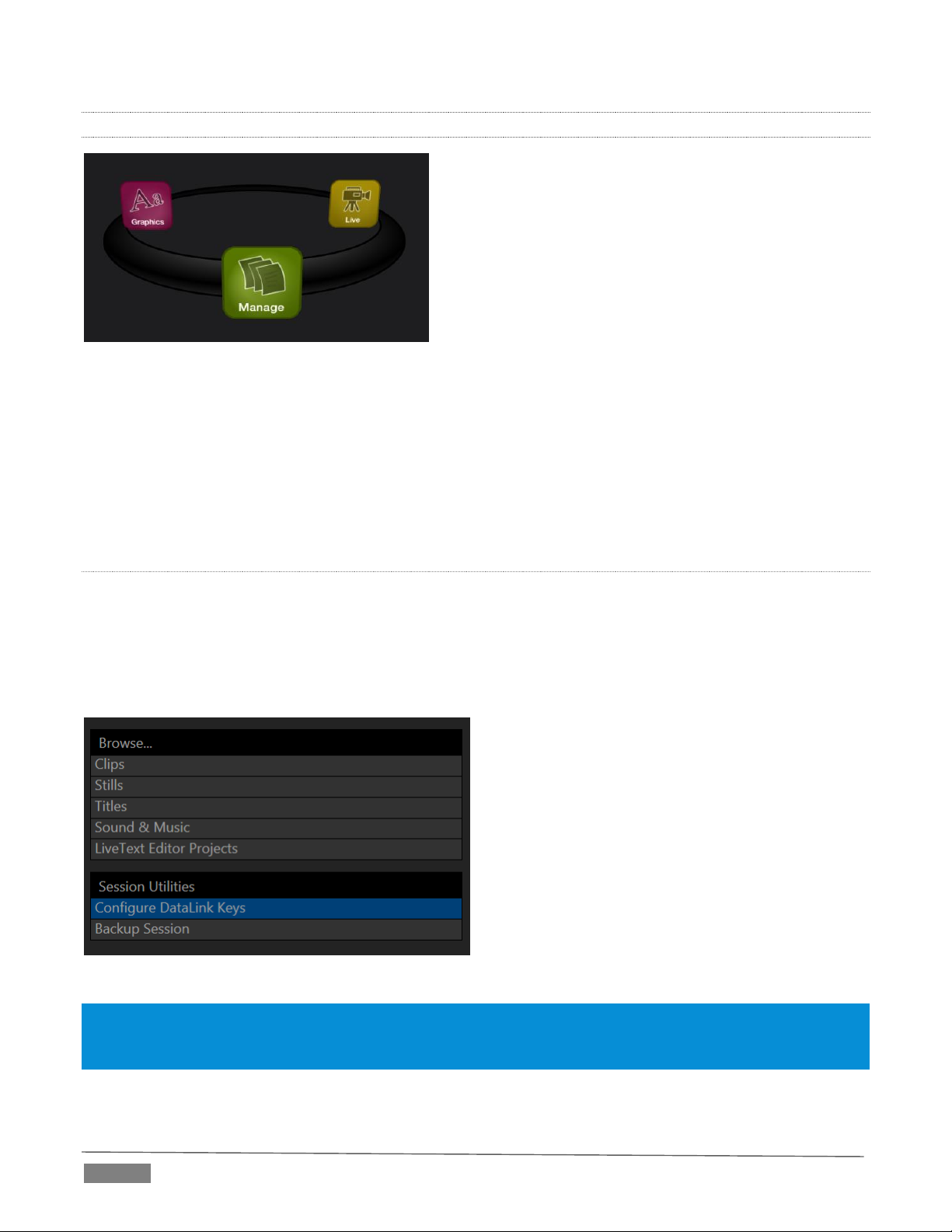
5.3.3 MANAGE
FI GUR E 50
Various TriCaster components provide filebins to permit you to manually administer files related to their
projects, playlists, and so on. The Manage icon in the Session Page provides an alternative approach to file
management.
At times you may find it useful to be able to quickly access the various files associated with specific sessions.
Selecting Manage refreshes the options pane on the right-hand side of the Session Page with a number of
convenient items.
BR OWS E
Under the label Browse, you will see direct links to the Clips, Still, and other content associated with the
current session. Clicking one of these links (or selecting it with the up/down arrow keys and pressing Enter)
opens a system file explorer.
You can use the familiar features and shortcut keystrokes in these windows (Cut, Copy, Paste, Rename, Delete
and so-on) to manage the session content.
FI GUR E 51
Hint: Of course, you can open several of these folders simultaneously, and navigate these file windows to other
locations as well. For example, you might copy the title page (.cgxml) files from the Titles folder of one session into
the Titles folder of a different one before deleting the first session.
Several other important features are contained in the Manage group, discussed next.
Page | 54
Page 67
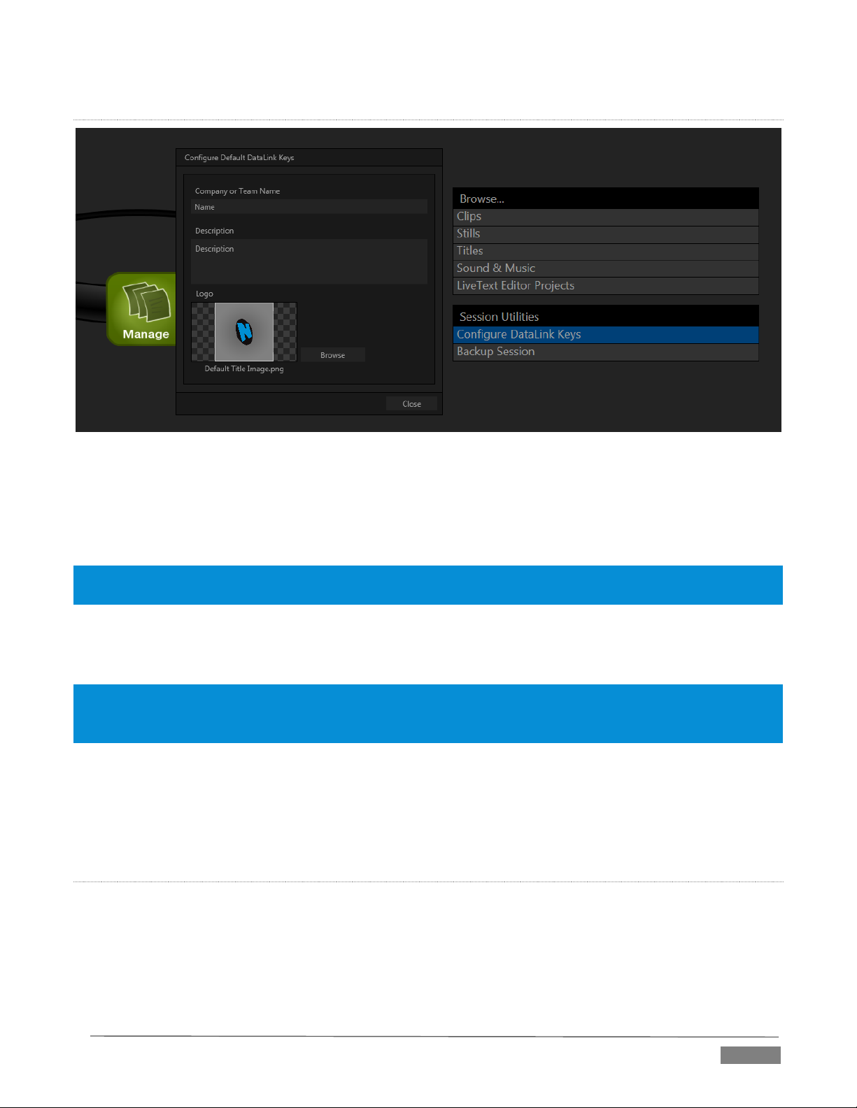
CO NFI GURE DATALINK KE YS
FI GUR E 52
DataLink™ is an astonishingly useful TriCaster Advanced Edition exclusive, allowing the handling and
updating of text and image data from both internal and external source for use in title pages in realtime, as
well as other purposes. Briefly, DataLink tracks variables, called DataLink keys, and their values, and updates
these values on-the-fly when keys are used in title pages.
Hint: DataLink keys can serve in other ways, too, as for example to automatically insert information such as time
or scores into labels and comments of social media uploads, or as instant replay clip metadata.
Since DataLink falls into the general realm of automation and also has access to external sources, complete
coverage of its features and capabilities is found in the companion Automation and Integration Guide included
with this product; but we’ll mention a few highlights as we go along in this manual as well.
Hint: If not today, we urge you to make definite plans to read the DataLink chapter in the Automation and
Integration Guide. Without exaggeration, DataLink is a game-changer. It can save you a great deal of time,
prevent embarassing and potentially costly mistakes, and lift your productions to new heights.
The Manage group link labeled Configure Datalink Keys opens a dialog that allows you to pre-assign values
to three special DataLink keys. These session keys serve as the default first and second line text inserts and
image used by many of the supplied template title pages. (By taking a moment to populate these keys with,
for example, a company name, motto, and logo, you will find much of the included graphic content ready to
use for a given production without ever having to type another line.)
BA CKU P SE SSI ON
Clicking the Backup Session button opens a system file explorer that you can use to assign a storage location
for the backup files. Backup operations can take some time, depending on the amount of content in the
session. For obvious reasons, then, it would be wise not to begin a major backup operation shortly before a
scheduled live production. A progress gauge is displayed during processing, and if necessary you may Cancel
the operation. Of course, the session to be backed up is the current session (to back up a different session,
return to the Home Page and Open a different session.
Page | 55
Page 68

The backup operation feature will determine whether all media used in the session is local (i.e., located in
folders named for that session), or whether some content is external – stored in other places on your system,
and included in the session using Add Media Location, or from folders belonging to other sessions. If all
session media is local the backup proceeds without further interruption.
When external media is used in the session, a dialog is presented stating "The following files are external to
the session. Would you like to import these files?" The optional actions in the dialog are:
Backup without importing
Import and Backup
Cancel Backup
Page | 56
Page 69

The TriCaster™ Live Desktop is the control center for all your live production work. It
provides control over switching, transitions and overlays, titles and graphics, audio
mixing, playback of digitized content, and much more.
In addition, streaming and recording features are located here, along with keying and
virtual set tools.
LIVE DESKTOP: OVERVIEW
The TriCaster™ Live Desktop is launched by creating (or opening) a session in the Startup Screen’s Home
Page, then selecting the LIVE icon and clicking Start Live Production.
SECTION 6.1 DISPLAY REQUIRE MENTS
The Live Desktop requires a minimum screen resolution of 1600x1050.
FI GUR E 53 (TR ICAS TER 80 00 SHOW N)
SECTION 6.2 OVERVIEW
TriCaster’s Live Desktop provides visual feedback for operations, including monitoring, live switching, and so
on. It is divided into five horizontal bands.
Page | 57
Page 70
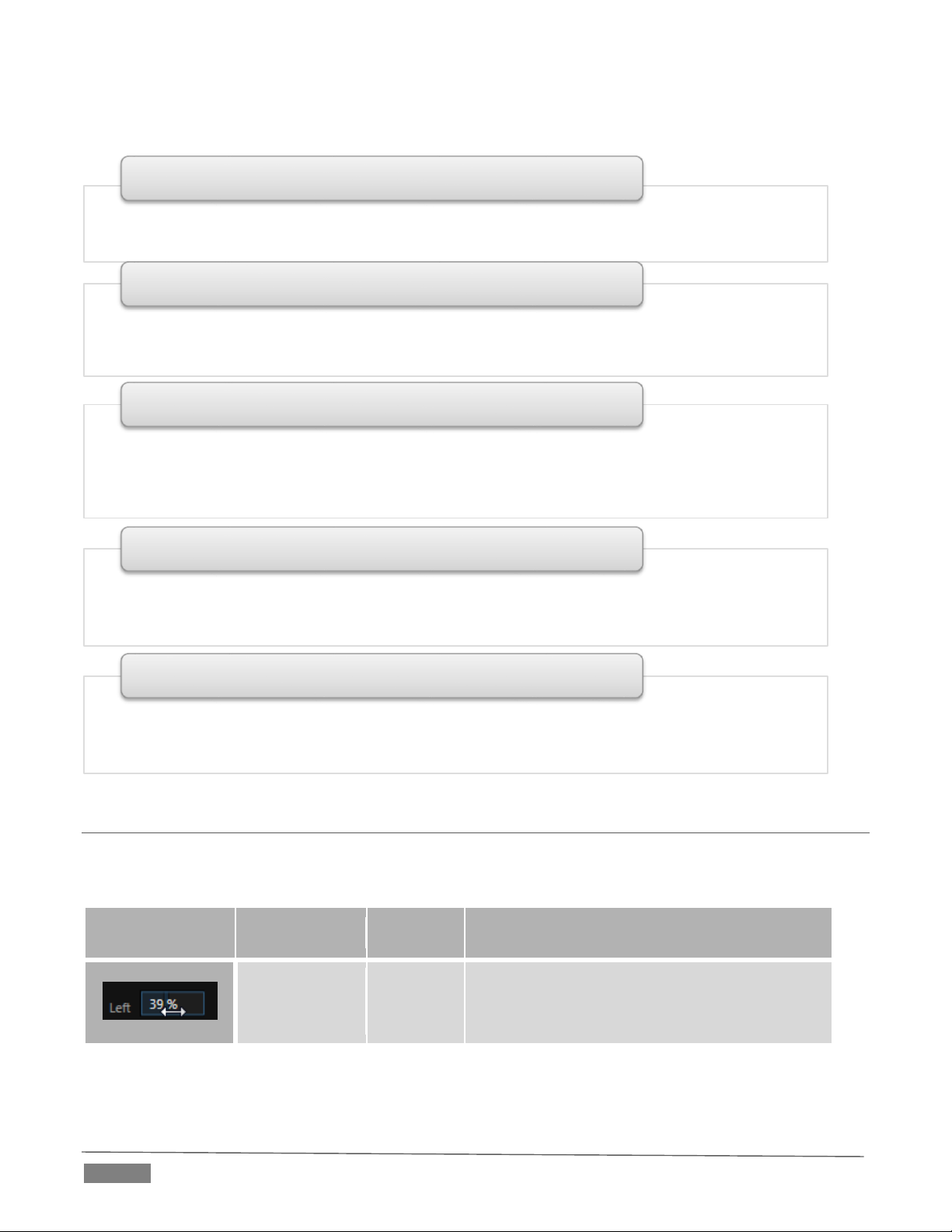
Control Type
Type
Examples
Usage
Numeric Slider
Gain, Pan
Drag in line with the control’s orientation to
raise or lower the current value.
• Quick access to interface options and important tools, including Publish and Macros along with
Record, Stream, Workspace and Timecode options.
1 - Dashboard
• User configurable layouts – monitor live inputs along with internal sources (such as DDRs, M/Es,
and Buffers) plus Look Ahead Preview and Program output
• Waveform and Vectorscope monitors
2 - Monitors
• Effect mode – control up to four primary video layers plus 4 overlay channels
• Mix mode – secondary switcher controls plus 4 overlay channels
• Each M/E includes dedicated an extensive complement of Keyers, transition generators,
scaler/positioners, and more
3 - M/Es
•Switcher rows – Program and Preview rows
•Transition controls – T-bar and Delegate buttons
• DSK video layer configuration and controls
4 - Switching
• Internal Media Players and Buffers)
•PTZ (robotic) camera controls
• Audio (mixer) – input configuration, level control, EQ and Compressor/Limiters
5 - Tabbed Control Modules
From top to bottom, these are:
SECTION 6.3 CONTROL TYPES
You will find various control types used repeatedly in TriCaster’s Live Desktop. Some examples are shown in
the table below.
Page | 58
Page 71

Rotary slider
Position,
Size,
Rotate
Drag up-down to adjust one value, left-right to
adjust the other value, diagonally to adjust two
different values simultaneously.
Hold down Alt while dragging vertically to
modify the third value (Z) when provided.
Rotary Knob
(single-value)
Audio Gain
Drag left-right to adjust the current value.
Combo-Slider
Transition,
Zoom
Duration
Drag left/right to raise or lower the current
value
Click the digits to type in a new value
Or click the triangle to open a drop-down
menu
To make very fine adjustments to slider values, hold down the Ctrl key while dragging the mouse (this
increases accuracy by 10x). Hold down the Shift key and double-click most controls to reset them to their
default values.
SECTION 6.4 CUSTOMIZING THE LIVE DES KTOP
TriCaster’s Live Desktop layout can be adapted to many different scenarios, and provides a number of
customization options that can be of benefit in your workflow. In this section, we’ll touch on several of these.
6.4.1 RENAME INPUT
As charming as descriptive names like Camera 1, DDR 2 and M/E 5 are, you may wish to change these labels
to something more appropriate for your local needs.
FI GUR E 54
Page | 59
Page 72

To do so, simply right-click on one of the following items to open the Rename Input dialog (Figure 54):
Any monitor in the Live Desktop or external Multiview
Any Switcher source button
The Rename Input dialog has either several editable text fields, including Video (the label shown under
monitors), a shorter Switcher Button label and, sometimes Audio – the name shown for the audio input with
the same number.
TriCaster Advanced Edition also provides a large Comment box here. Since both the longer Video label and
Comment can be used by DataLink to automatically update title pages as individual inputs are displayed, this
is a particularly useful feature.
6.4.2 WORKSPACES AND MIN/MAXIMIZE
Various layouts and custom monitoring options for the Live Desktop and Multiview are provided in the
Workspace menu. When a Multiview monitor is in use, the two Workspace preset options can be combined
with great flexibility, letting you see what you want to see where you want to see it. It’s easy to set up
complementary displays in the two monitor areas.
For example, you might show main Program and Preview monitors along with all 8 M/Es on the Live Desktop.
Meanwhile, the Multiview monitor could display up to eight live Camera feeds plus Media Players, as well as
the (program) output and B row selections for a specified M/E set to Mix mode.
FI GUR E 55
Notice too that you can also drag both the horizontal divider between the Live Desktop monitor pane and the
Switcher, and the divider between the Program and Preview panes at right and the viewports at left. You can
even move the horizontal divider all the way up to the bottom of the Dashboard, thus hiding the Desktop
monitor pane entirely (Figure 55), providing much more room for other modules in the process.
Hint: Reset the horizontal divider to its default locations by double-clicking it.
Page | 60
Page 73

Click the Mix Effects label or an M/E tab between the Monitor and Switcher sections to toggle display of the
M/E pane – or press the keyboard shortcut “m”.
A number of further workflow and interface options that can be very valuable are found in the TriCaster
Options menu, discussed shortly (Section 7.1).
Page | 61
Page 74

Page 75
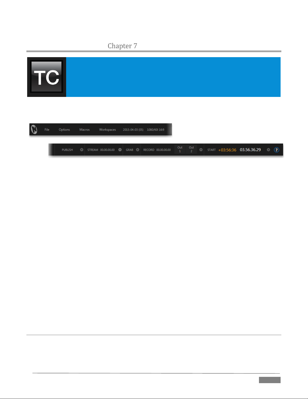
TriCaster’s Dashboard groups important production features and system display controls
in one convenient place for quick access and review.
As well, the Dashboard serves to provide information on the current session, status
updates and storage usage, along with timecode and the TriCaster Options menu.
THE DASHB OARD
TriCaster’s Dashboard is home to a number of important displays, tools and controls. Prominently located at
the very top of the Live Desktop, the Dashboard occupies the full width of the screen.
FI GUR E 56
The various elements comprising the Dashboard are listed below (starting from the left):
1. File menu
2. Options menu
3. Macros menu (see Chapter 17)
4. Workspaces menu (see Chapter 10)
5. Session Information (display)
6. PUBLISH button and Configuration
7. STREAM button and Configuration (see Chapter 18)
8. GRAB button and Configuration (see Chapter 20)
9. RECORD button, Replay Pad, and Configuration (see Chapter 20)
10. Time Display(s) and Configuration (see Section 8.2.9)
11. Information (see Section 4.1)
Of these items, some are so important that they rate their own chapters. Others are detailed in various
sections of this guide (cross references to the relevant sections of the manual are provided above). In this
chapter, we’ll focus on those Dashboard features which are not discussed in depth elsewhere.
SECTION 7.1 FILE MENU
This menu drops down to reveal the following items:
Eject – opens a sub-menu that lets you safely disconnect selected storage volumes
Page | 63
Page 76

Import – easily add media files from external sources to the appropriate session folders,
automatically transcoding them to friendly formats for optimal playback if necessary. (The Import
Bin’s features are similar to those of the Publish Bin.)
Share Media Folders and Buffers (see Section 11.4)
Exit – close your live production session, and return to the Session page of your TriCaster’s Startup
screen (all session settings are stored on exiting)
SECTION 7.2 OPTIONS MENU
A number of very useful interface and workflow options are presented in the TriCaster Options menu.
Tabs Follow
o Enable Follow Preview Row for All Inputs to display the tabbed pane for a Preview row source
automatically on selection changes (for M/E selections, the M/E pane must be maximized in
order to see the M/E tab update).
o When Tabs Follow Preview for M/Es is checked, only the M/E pane updates (when you select
an M/E as source on Preview).
Hint: Control surface delegate operations can sometimes result in a tabbed module that you want to view being
obscured when certain options are enabled. When this happens, press the control surface Delegate button again
to re-display the tabbed pane you are interest in.
FI GUR E 57 (TR ICA S TER 80 00 SHOW N)
(TriCaster 8000 only) Control System(s) Remotely – select one (or more) TriCaster 8000’s detected
on your local network, and all control operations you perform using the user interface, the control
surface, or keyboard will be echoed to the controlled system – see Section 17.4.
Default Media File Level – the default ‘per-clip’ audio level applied to imported media files is
controlled by this option.
The Hotspots menu offers Disable All Hotspots and Disable Hotspots for Sources Not on Output options
to prevent macros from being triggered inadvertently.
Page | 64
Page 77

Enabling Lock Mouse to Primary Monitor prevents the mouse from traveling into the external
Multiview display.
Enable Autoplay Out on M/Es – You may find it useful to enable Autoplay’s ‘transition-out when
nearing the end of play’ feature for M/E’s (Mix mode). By default, this option is off.
SECTION 7.3 MACROS
Macros are an extremely important TriCaster feature. Sufficiently so, in fact, that not only have we given
them a place of their own in the User Guide (Chapter 17), but they are also discussed in greatly expanded
detail in the accompanying Automation and Integration Guide.
SECTION 7.4 WORKSPACES
The Workspaces menu opens when clicked to reveal two groups labeled Interface and Multiview. These
control the monitor viewport layouts shown on the Live Desktop and external Multiview displays.
Workspace features are discussed in Section 10.1 under the heading Interface and Multiview.
SECTION 7.5 INFORMATION PANEL
An information display in the Live Desktop titlebar provides a number of useful items. Displayed information
includes:
(Session Name)
(Session format)
Status message display
FI GUR E 58
The Status message area sits next to the session information display, but is hidden when no message is
shown. When TriCaster needs to inform you regarding system events or conditions, text messages
replace the normal information display. Status messages may pertain to operations or system
conditions; they may be benign, as in *Figure 58, or cautionary.
* A brief initialization is required following system startup for DDR video playback to stabilize.
During this brief ‘warm-up’ period, an initialization countdown appears in the Status message
display...
The display automatically clears itself a few moments later so as not to pose an unnecessary distraction.
Page | 65
Page 78

Page 79

TriCaster™ provides extensive control over your video sources, along with related
creative features. Each video source (internal and external) has its own Proc Amp, keyer
(LiveMatte™) and Crop (‘garbage matte’) features. Input Configuration panels are also
home to TriCaster’s powerful realtime Hotspot and Tracker features. In addition, the
number and flexibility of TriCaster’s outputs is astonishing, and we’ll discuss these fully
in this chapter.
I/O CONFIGURATION
In a break with orthodoxy, let’s begin our discussion at the end – that is, with a consideration of TriCaster’s
plentiful Output Configuration features.
SECTION 8.1 OUTPUT CONFIGURATION
FI GUR E 59
Roll the mouse pointer over the Program monitor to reveal a Configure button (Figure 59) at right in the
titlebar below the display. Click it to open the Output Configuration panel. The features offered in this panel
vary by model.
FI GUR E 60 (TR ICAS TER 80 00 SHOW N)
Page | 67
Page 80

FI GUR E 61 (TR ICA STER 410 SHOW N )
8.1.1 OUTPUT TAB
The Output Configuration panel contains a pane governing TriCaster’s outputs, and may also include a tabbed
pane with Genlock & Failsafe options (Failsafe only for TriCaster 410) and settings. (TriCaster Mini does not
have genlock or failsafe options.)
PR IMA RY OU TPU T S
The first tab, labeled Output, provides control over all of TriCaster’s Output channels. Each of these is in some
ways unique. Depending on the model, either the first two (Mini and 2-RU models) or three (4-RU models)
of these are of particular interest.
Along with the supplementary HDMI output listed next, these primary outputs support the largest
number of optional video sources.
The primary outputs (plus HDMI) can uniquely follow the delegated M/E. or a Switcher color group.
o All other outputs can be assigned to follow a primary output, or show a designated Switcher
source.
Uniquely, Output 2 can be tasked with sending an alpha channel matte to downstream systems.
Let’s consider the optional settings provided by primary outputs:
Video menu – assign any source from the following list to either Output 1 or Output 2:
o Program
o Program (Clean)
o Preview (look ahead)
o Cameras 1-(4 or 8)
o Network 1 or 2
o Media Players
DDR 1
DDR 2
GFX 1
Page | 68
Page 81

GFX 2
o Output from M/E 1- (4 or 8)
o Any single Buffer
o Follow
M/E Preview
M/E Program
Green (FX)
Gold
Blue Red
o Black
o Alpha Matte – Output 2 only
Embedded Audio menu – choose which audio is presented on the corresponding SDI, HDMI, Stream and
Network outputs (Analog Outputs 1 and 2 connections always carry Master and Aux sound, respectively):
o Outputs
Master 1, 2 (sound from the Master 1 and 2 busses)
Aux 1, 2 (sound from the Aux 1 and 2 busses)
(See Section 15.7.2 for discussion of TriCaster’s internal audio busses).
o Inputs 1-(4 or 8) – sound from any single audio input
Resolution menu – Output 1 is always at session resolution. For other outputs, select the video format for
downstream devices you intend to connect to the corresponding output:
o 1080i or 1080p – depending on the session format
o 1080i
o 720p
o 480i (4:3) – interlaced NTSC sessions
o 480i (16:9) – interlaced NTSC sessions
o 480p – progressive sessions
o 576i (4:3) – interlaced PAL sessions, Multi-format TriCasters only
o 576i (16:9) – interlaced PAL sessions, Multi-format TriCasters only
o 576p – progressive PAL sessions, Multi-format TriCasters only
Note: Output 1 always transmits video in session format, thus shows Resolution display rather than a menu.
Analog Out menu (not present on TriCaster 410 or TriCaster Mini) – select the video connection type
for downstream devices you intend to connect to the corresponding output:
o Component
o Composite + Y/C
Note: The only analog connection type suitable for HD video is Component. The Analog Out menu for primary
outputs are automatically set to Component when the selected Resolution is HD.
Choosing Component or Composite + Y/C results in the output connectors in the corresponding row
being configured as shown in the following table:
Page | 69
Page 82

Connection Type
BNC 1 (SDI)
BNC 2 (Y)
BNC 3 (Pb)
BNC 4 (Pr)
Component
SDI Y Pb
Pr
Composite + Y/C
SDI
Composite
Y
C
Note: TriCaster’s digital (SDI) video outputs are always active, even when the analog outputs in the same group
are in use. HDMI display devices will typically show black when if they do not support video displays of the format
(resolution, etc.) selected as source.
Generally, source formats that are inconsistent with the current output resolution setting are automatically
conformed when possible. In some cases, such as non-standard image or iVGA sources, the output format may be
modified to provide a suitable display. It’s best to avoid non-standard sources whenever possible.
AL PHA MAT TE
The Video source menu options for Output 2 include a switch labeled Alpha Matte. This feature can be used
independently, or supplement the Act as Alpha option (discussed in Section 8.2.2).
An alpha matte can be automatically derived from suitable sources. It might be the matte from a LiveMatte
keyer effect, allowing Output 2 to support downstream compositing of the full color source. Or, it could be
drawn directly from an image or Title Page in a Media Player. It could just pass-through the matter from an
upstream alpha channel source. Simply enable the switch in the Output Configuration panel, and select a
suitable source using the same menu.
Note: Generally, the source’s Resolution should match session format when supplying an Alpha Matte signal to
downstream devices.
GE NER AL NO TES
Here are some other noteworthy facts related to output:
For SD session formats, session aspect (4:3 or 16:9) is respected on output (e.g., when the session is
SD 16:9, video output is also 16:9).
For HD sessions (which are always 16:9), interlaced SD video from a primary output and any output
set to Follow it) can use either a 16:9 image aspect or as (side-cropped) 4:3 video, as noted earlier
when discussing the Resolution menu.
Hint: Even if you are not using the HDMI output, , it can be especially useful, since a) it supports the full array of
optional sources, and b) secondary outputs can follow it. For example, you might set HDMI to ‘output’ an M/E,
and then send that M/E to the Network output (which is not normally able to output an M/E directly).
ST REA M AND NE TWORK
These outputs (provided on a certain models) independently offer a subset of the options available for
Outputs 1 and 2. Video menu options include:
Cameras 1-(4 or 8)
Network input sources
Media Players
Buffers
Follow 1- (3 or 4)
Page | 70
Page 83

Choosing Follow 1- (3 or 4) transmits the same video source, at the same resolution, as the ‘followed’ output.
FI GUR E 62
Network Output sends audio and video across a LAN (Local Area Network) to the Net inputs of another
TriCaster, and is enabled or disabled using the switch at left. A De-Interlace option is provided for Network
out. This is useful for connection to downstream systems that re-stream TriCaster’s network video output
but lack native ability to de-interlace it (TriCaster’s own streaming output is always de-interlaced).
Streaming Output is more complex, since there are so many different ways to stream. In this panel, you can
configure the audio and video sources sent to output. All other options and settings relevant to streaming
are located in the Streaming Configuration panel – see Chapter 18 for a full discussion of this important topic.
DI SPL AY OUTPUTS
FI GUR E 63
Two rows at the bottom of the configuration panel are labeled Display. The corresponding output ports are
intended to supply video to projection systems or other display devices. The physical Display connectors
may vary by model, but are typically presented physically on TriCaster’s rear connection panels as HDMI and
either DVI or VGA ports. Video Source options are the same as other secondary outputs. No audio is supplied
to these connectors.
When a downstream monitor is detected on a Display port, the corresponding Resolution menu permits
selection of a suitable resolution (typically, an incorrect selection here will result in an ‘out of range’ error
message being displayed on the downstream device). Switches provided at left in each row permit the
Display ports to be selectively disabled when they are not required.
Note: TriCaster Mini, depending on the model, may also provide CASE DISPLAY setup features, providing access to
a number of useful display alternatives for the side-panel LCD screen.
8.1.2 GENLOCK & FAILSAFE
TriCaster’s Genlock feature allows it to ‘lock’ its video output to a reference video signal supplied to its
Genlock input connector. (Note that neither TriCaster 410 nor TriCaster Mini include Genlock options.)
Page | 71
Page 84

Hint: The term “genlock” refers to
Professional video devices often
provide a “genlock input”, which
allows an external reference signal
(often referred to as ‘house sync’)
The output of video devices
connected in this manner is
synchronized to the reference
signal, and they are referred to as
This synchronizes TriCaster output to other external equipment
locked to the same reference. Genlocking is not a requirement, but
it is very beneficial, and you should definitely use it if you have the
“generator locking”.
capability.
TriCaster mixes and switches output from up to eight camera
sources (8-input models). Miniscule local timing differences
between these may force tiny delays during switching operations,
which can also contribute to throughput latency.
to control its video timing.
Thus, serving i) TriCaster’s Genlock input and ii) other video
devices in the chain with a single reference is the best approach.
You could think of it this way:
‘genlocked’.
Genlocking your cameras has the effect of locking their output
together, ensuring optimal synchronization for live switching.
This may result in throughput latency benefits.
Supplying the same sync source to TriCaster’s Genlock input ensures a
match between TriCaster output and any downstream video devices required to
handle both it and other (genlocked) sources.
Note: Digital audio is less tolerant in certain respects than analog. Some devices require SDI sources to be
genlocked when mixing digital audio (whether for recording or live production).
TriCaster, however, includes dynamic audio re-sampling for each input. Genlocking of SDI audio/video sources is
not a requirement. Still, genlocking sources and TriCaster to a house reference signal, or genlocking the cameras
directly to the TriCaster output is encouraged (to genlock cameras, see your camera manual).
Locking all devices to house sync is important, but this alone does not actually ensure a perfect downstream
match. Consider an army marching along: each step the soldiers take occurs at precisely the same moment,
so we could say their timing is synchronized.
Even so – problems result if one soldier leads with the left foot while everyone else is on the right. Or perhaps
everyone is evenly spaced and perfectly aligned but for one misfit who ‘tailgates’ the soldier ahead of him
and keeps stepping on his heels.
This is essentially why TriCaster provides several adjustments in its Genlock section. The Horizontal and
Vertical Position settings pin the image in the proper space in the frame, and in doing so could be likened to
making sure each marching soldier is in position relative to his fellows (as viewed from above).
The Phase setting ensures proper color alignment, corresponding to making sure everyone is on the left or
right foot at the same time.
VE RTI CAL POSI TION, HOR IZO NTA L PO SIT ION AND PHASE
Page | 72
Page 85

FI GUR E 64
Thus, the Vert Position, Horiz Position and Phase settings allow you to tweak synchronization to arrive at an
optimum match between devices. Typically, these settings are fine-tuned with the aid of a downstream
Vectorscope and Waveform Monitor. (A discussion of these adjustments goes beyond the scope of this
manual, but a quick online search for the keywords “genlock” and “adjust” turns up a number of excellent
references).
RE FER ENC E TYPE
The ‘bi-level’ reference signal long used for standard definition television is often used for genlocking both
SD and HD installations.
However, if you are supplying an HD reference signal to TriCaster’s Genlock Input (and your other
equipment), select the HD (Tri-level) switch in the Reference Type area of TriCaster’s Genlock settings.
Note: Reference Type options do not appear for SD sessions.
8.1.3 CENTER FREQUENCY
This setting is applied when a genlock reference signal is not in use. To adjust the setting, supply color bars
to an input and pass TriCaster’s video output to a downstream vectorscope. The vectorscope display is
completely stable when Center Frequency is properly adjusted.
Note: See also Section 8.2.3, Frame Sync .
Page | 73
Page 86

8.1.4 FAILSAFE
FI GUR E 65
TriCaster’s multi-tiered ‘Always on Air’ hardware and software failsafe systems (see Section 2.6.2) provide
confidence that short of a complete power failure the show will go on.
In some studio settings, however, more elaborate hardware failsafe systems may be in use. Typically, such
systems take over broadcast duties whenever the output signal fails. In such cases, TriCaster’s failsafe video
passthrough mechanism (which ensures that video output continues even in catastrophic circumstances)
can actually prevent the external system from engaging.
For this reason, a Failsafe section has been added to Output Configuration. Its sole raison d’être is to provide
a switch allowing you to disable the A/V passthrough when necessary. By default, A/V passthrough is off.
Hint: Only use fail-safe when a stable video source is connected to video Input 8.
SECTION 8.2 INPUT CONFIGURA TION
FI GUR E 66 (TR ICAS TER 80 00 SHOW N)
TriCaster’s input monitors have contextual tools that appear when you roll the mouse pointer over in the
footer (that is, the titlebar below each monitor). The right-most button is a Configure button (gear). Clicking
it opens the Configuration panel for the corresponding source (Figure 66).
Page | 74
Page 87

• Analog source, high definition, interlaced or PsF (Progressive Segmented Frame)
• 1080/60i , 21080/50i, or 1080/24p
• 1920x1080 pixels, 16:9 picture aspect
• Connected to TriCaster by Y, Pr and Pb input connectors
1080i (Component), 1080/30PsF (Component), 1080/24p Telecine
(Component)
• Digital source, high definition, interlaced
• 1080/60i or 21080/50i
• 1920x1080 pixels, 16:9 picture aspect
• Connected to TriCaster by SDI input connectors
• Optionally carries embedded audio
1080i (SDI)
8.2.1 CONNECTION TYPE
FI GUR E 67
The Configuration panel for non-network external video inputs features a Connection type menu at the top
of its Input Settings tab. Connection menu options vary depending on the Video Standard for the session.
TriCaster Multi-standard provides PAL and NTSC-J session options, in addition to NTSC.
The Connection Type menu options for a PAL session list PAL HD and SD format options. Choosing NTSC as
the session Video Standard results in a Connection Type list with appropriate formats, and it is similar for
NTSC-J. Changing from one Video Standard to another requires opening a new session.
Hint: All connected cameras must conform to the current Video Standard for the session.
AU TO-DETECT (SDI)
TriCaster Advanced Edition’s Auto Detect (SDI) feature makes configuring SDI sources easy. Generally, you
can simply connect a camera and see the signal from their SDI sources immediately, without any need to set
resolution and framerate options. (Note that this feature requires that the source is supplied in an HD format
for HD sessions, or an SD format for SD sessions. So, for example, if you connect an HD-SDI camera in an SD
session, Auto-Detect will work as expected.)
SUPP ORTED FORMATS
Other standard options are described below (note that TriCaster 410 and TriCaster Mini do not support
analog video input options):
Page | 75
Page 88

• Digital source, high definition, progressive scan, or PsF (a hybrid)
• 1920x1080 pixels, 16:9 picture aspect
• Connected to TriCaster by SDI input connectors
• Optionally carries embedded audio
1080/30p (SDI), 1080/30PsF (SDI), 1080/24p (SDI), 11080/24p Telecine
(SDI), 21080/25p (SDI), 21080/25PsF (SDI)
• Analog source, high definition, progressive scan
• 1280x720 pixels, 16:9 picture aspect
• Connected to TriCaster by Y, Pr and Pb input connectors
720/60p (Component), 2720/50p (Component)
• Digital source, high definition, progressive scan
• 1280x720 pixels, 16:9 picture aspect
• Connected to TriCaster by SDI input connectors
• Optionally carries embedded audio
720/60p (SDI), 720/30p (SDI), 720/24p (SDI), 2720/50p (SDI), 2720/25p (SDI)
• NTSC analog format, standard definition, interlaced
• 720x480 pixels, 4:3 picture aspect or anamorphic 16:9 picture aspect
• Connected to TriCaster by Y, Pr and Pb input connectors
480/30i (Component)
• NTSC digital format , standard definition, interlaced
• 720x480 pixels, 4:3 picture aspect or anamorphic 16:9 picture aspect
• Connected to TriCaster by SDI input connectors
• Optionally carries embedded audio
480/30i (SDI)
• NTSC (S-Video) analog format , standard definition, interlaced
• 720x480 pixels, 4:3 picture aspect or anamorphic 16:9 picture aspect
• Connected to TriCaster by Y and Pb input connectors
480/30i (Y/C)
The standard definition options listed below are provided in both 4:3 and 16:9 versions:
Page | 76
Page 89

• NTSC analog format , standard definition, interlaced
• 720x480 pixels, 4:3 picture aspect or anamorphic 16:9 picture aspect
• Connected to TriCaster by Y input connector
480/30i (Composite)
• PAL analog format, Standard definition, interlaced
• 720x576 pixels, 4:3 picture aspect or anamorphic 16:9 picture aspect
• Connected to TriCaster by Y, Pr and Pb input connectors
2
576/25i (Component)
• PAL digital format , standard definition, interlaced
• 720x576 pixels, 4:3 picture aspect or anamorphic 16:9 picture aspect
• Connected to TriCaster by SDI input connectors
• Optionally carries embedded audio
2
576/25i (SDI)
• PAL (S-Video) analog format , standard definition, interlaced
• 720x576 pixels, 4:3 picture aspect or anamorphic 16:9 picture aspect
• Connected to TriCaster by Y and Pb input connectors
2
576/25i (Y/C)
• PAL analog format , standard definition, interlaced
• 720x576 pixels, 4:3 picture aspect or anamorphic 16:9 picture aspect
• Connected to TriCaster by Y input connector
2
576/25i (Composite)
1
The ‘telecine’ option removes ‘2:3 pull-up’ in output from cameras claiming 24PsF but actually supplying
video at 30 fps (to make it suitable for 24P use sessions).
2
Multi-standard TriCaster PAL connection type
TriCaster optionally allows one or more neighboring pairs of video inputs to be combined as a single ‘video
+ alpha’ channel (sometimes also referred to as “fill and matte”).
8.2.2 ACT AS ALPHA
Page | 77
Page 90

FI GUR E 68
The ability to configure one input as the alpha channel source for another
is absolutely invaluable for installations employing video feeds from high
end external CG and chromakeying systems (such as Chyron® and
Ultimatte® ).
To use this feature, select Act as Alpha Channel for Input (#) as the
Connection Type in the Input Configuration panel for an even-numbered
input.
Note: The input configuration (video format and connection type) for the alpha input is automatically configured
to match the fill source it is paired with.
8.2.3 FRAME SYNC
FI GUR E 69 (TR ICA STER 800 0)
TriCaster internal Frame Sync is enabled for all sources by default, allowing you to work with a wide array of
potential video sources without concerns about video timing. For TriCaster 8000 (only), it is possible to
ensure the very lowest possible throughput latency for genlocked sources by disabling Frame Sync.
Sources with Frame Sync disabled must be genlocked, and further, must be ‘in phase’ (within 180° of the
current switcher output); otherwise, video from the source will simply not be visible.
In practice, then, disable Frame Sync for your genlocked sources, adjust the Phase setting (see Section 8.1.2)
until video is displayed and you should be all set.
Note: If Frame Sync is enabled or disabled for one source in a ‘Fill + Alpha’ input pair, the Frame Sync setting for
the corresponding input channel is automatically updated to match.
8.2.4 EDGES
It is very common for a source to be supplied with unintentional inclusions; these are often items that remain
after chromakeying is applied, but which need to be removed along with the background. (Common examples
include microphones or lighting fixtures dangling from above, or perhaps a harsh crease, blemish or tear in
the background screen.) Or, as is frequently the case, the source video itself may have a few pixels of black
or video ‘noise’ along one or more of its edges.
Cropping settings in the Edges control group can be used to remove such unwanted ‘garbage’ from the scene,
or used independently for other purposes – such as to isolate some portion of the screen for use as a ‘Picture
in Picture’ overlay source.
Page | 78
Page 91
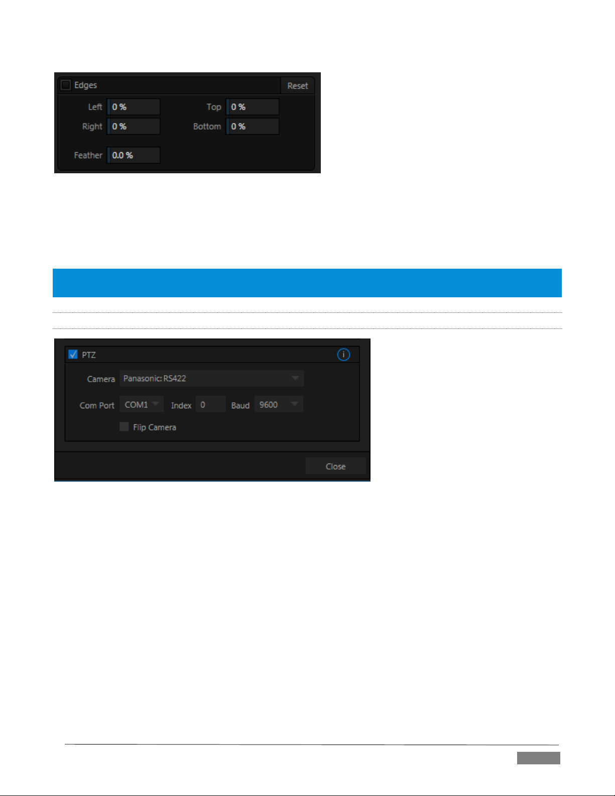
FI GUR E 70
Essentially, the numeric controls in this group allow you to define independent margins for the frame. Drag
left or right on the number fields to adjust the values interactively, or double-click a field to type a value using
the keyboard. The region defined by these controls will be completely cropped. Use the Feather setting
(TriCaster 8000 only) to soften the edges.
Hint: For added convenience, similar cropping tools are available separately in the Position panels of DSK channels
and M/Es.
8.2.5 PTZ
FI GUR E 71
PTZ (pan-tilt-zoom), or ‘robotic’ cameras can play important roles in certain types of productions. These
systems range widely in price, from a few hundred dollars to those in the ‘six figure’ range, with an equally
diverse range of quality and features.
Generally, remote control of PTZ cameras involves sending instructions to the camera across either serial
(RS232. RS422, orRS485) or network connections. TriCaster support for both types (see note below).
connection settings shown in the PTZ tab (Input Settings tab) update depending on which Camera type you
select.
Choose your camera protocol (or one similar to it) using the drop-down menu, and then enter (or select)
appropriate settings for the unit. The Flip Camera switch inverts the image, helpful when the camera is
mounted in an upside-down orientation. It also affects the pan and tilt controls, when possible (this support
varies by camera).
Page | 79
Page 92

As TriCaster does not have an external serial port, you will need to use a third party USB-to-Serial Port
adapter for PTZ cameras requiring a serial connection. Windows will automatically assign a COM port
number to the adapter, usually COM 1. In some cases, you may wish to manually assign it to a specific port.
FI GUR E 72
Exit to Windows from TriCaster’s Adminstration Mode screen (Section 5.2.3) to access the controls shown in
Figure 72. Refer to the documentation provided with your adapter for further directions.
8.2.6 COLOR CONTROL
FI GUR E 73
Page | 80
Page 93

TriCaster Advanced Edition provides extensive color control processing options for every video source.
These are hosted in the Color tab of the Input Configuration panel.
AU TO COLO R
Lighting conditions can change dramatically during many live events, especially those held outdoors. Adding
to this problem, production usually involves multiple cameras and, all too often, these may not have uniform
color characteristics. Ensuring consistent color when switching from one angle to another, avoiding
unwelcome brightness or color shifts as evening falls or when a cloud obscures the sun briefly can be
troublesome, and expensive.
To help you overcome these problems, TriCaster Advanced Edition provides Auto Color, a unique feature
capable of dynamically adapting the color characteristics of your video sources as lighting conditions vary.
For many productions, simply enabling the Auto Color switch is all it takes to produce a show that looks
amazingly consistent.
MU LTI CAM
By default, each camera with Auto Color enabled is processed uniquely – without reference to other sources.
Often, though, even greater consistency can be achieved by treating sources in similar illumination
environments as a group. Enable Multicam for several cameras causes Auto Color to evaluate and adjust
these cameras in unison. You might, for example, enable Multicam for court-side cameras in an interior
sports venue, while treating exterior or studio feeds individually.
LI STE N ONLY
The Listen Only switch allows you to include a source in the Multicam group without adding its own feed to
the group evaluation. Thus a camera trained on a giant purple dinosaur can be automatically corrected
without disproportionately biasing the group evaluation and consequent Auto Color correction.
Alternatively, one might enable Multicam for a number of sources, turning Listen Only on for all but one
camera – effectively making that camera the color reference all other cameras in the group will follow.
Note: The Proc Amp, discussed next, is downstream of the Auto Color system. This allows you to apply further
manual color adjustments to your individual sources, whether for fine tuning or to achieve a specific “look”.
PR OC AMP
FI GUR E 74
A switch at the top of the Proc Amp control group toggles the feature on/off. Other controls operate as
follows:
Page | 81
Page 94
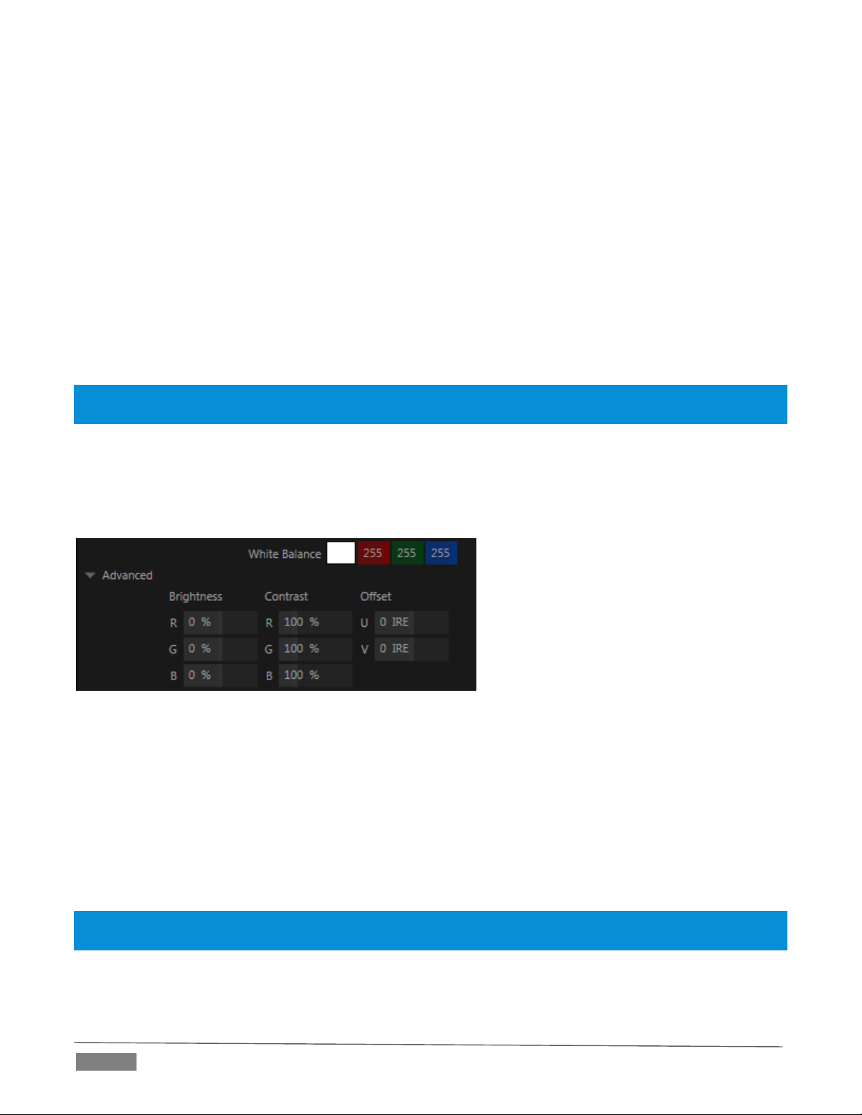
Brightness: Adjustment range from -50 to +50 IRE (the default being 0). As reference, the full luminance
range of the visible portion of a video signal can be thought of as ‘100 IRE units’ (named for the Institute
of Radio Engineers) – ignoring minor regional variations.
Contrast – Adjustment range from 25 - 400% (default 100%).
Hue – Adjustment range between -180° and +180°. Adjusts the master color of the video signal from the
attached source, swinging the entire image through the color wheel’s spectrum.
Saturation – Adjustment range from 0-500%. Zero saturation results in a ‘black and white’ picture;
increased saturation results in richer colors. High saturation values can exaggerate the color portion of
the signal.
(Note that over-saturated colors are considered illegal for broadcast transmission, and may result in
display problems on some devices.)
Hint: Proc Amp adjustments are also applied after LiveMatte is processed, which can help when composing
greenscreen shots to match a background or LiveSet.
White Balance – to automatically white balance, click and hold the mouse button on the Color well, and then
slide the ‘eyedropper’ pointer onto the monitor for the corresponding source. Release the mouse button over
a part of the image that should appear as white after processing.
AD VAN CED COL OR CONTR OLS
FI GUR E 75
This secondary control group is revealed when you click the triangle gadget beside its label.
In addition to per color channel (RGB) Brightness and Saturation sliders, it adds U Offset and V Offset controls.
The U portion of the video signal carries blue and yellow color information. Rotating the U Offset knob
clockwise shifts the signal toward blue, while a counter-clockwise twist shifts the signal toward yellow.
The V portion of the video signal carries red and green color information. Rotate V Offset clockwise to
shift the signal toward red and counter-clockwise to shift the signal toward green.
Hint: your TriCaster system provides Waveform/Vectorscope monitors, an invaluable aid to calibrating your video
sources.
Page | 82
Page 95

8.2.7 LIVEMATTE
The next tab in the Input Configuration panels is where TriCaster’s powerful realtime keying system for live
production, LiveMatte, is configured. Keying is a popular and powerful method of compositing multiple
images, whether photos, video clips or live camera streams.
FI GUR E 76 (TR ICA S TER 80 00 SHOW N)
The process involves eliminating a portion of the image (effectively cutting a digital ‘keyhole’ in it) to reveal
a user-defined background scene. It also plays an important role in the workflow of LiveSet, TriCaster’s
powerful virtual set technology.
LiveMatte’s controls are deceptively simple, making a great deal of complex digital manipulations easy to use.
Even so, much can be said about getting the best results. For that reason we’ve devoted a whole chapter in
this manual to discussing it – please see Chapter 13, LiveMatte .
Hint: When LiveMatte, Proc Amp, or Crop settings are active for a source, bright green, blue and yellow indicators
are lit under its monitor.
8.2.8 AUTOMATION
Automation is one of those wonderful things that really set TriCaster Advanced Edition apart from the
mundane. The Automation tab, located in the Input Configuration panels for all video sources is one of several
places where related features can be found.
Macros, discussed to a degree in Chapter 17, might be viewed as the basic building blocks of automation.
Macros can easily be recorded and edited, and equally easily they can be triggered by a keystroke shortcut,
control surface button, or similar means; but that isn’t really ‘automation’, is it? It’s actually a manual
operation. Somewhat obviously, automation should happen automatically, based on some predetermined
criteria. Thus the automatic transmission in your car upshifts and downshifts all by itself when certain
conditions are met. The automatic pilot on an airplane responds to flight conditions in a predetermined way,
without pilot input.
In similar fashion, the features of the Automation tab allow you to predetermine what will happen when
certain conditions are met. Consider the State Change control group.
Page | 83
Page 96

ST ATE CHAN GE
FI GUR E 77
Click the [E] button next to a ‘state’ (see Figure 77) to assign macros that will be executed on specific Switcher
operations that affect the specified state.
For example, the accompanying images depict macros that control the volume level of TriCaster’s SOUND
player. Whenever Camera 6 is newly selected on the Switcher’s PGM row, the Active macro will run.
Conversely, replacing Camera 6 with a different PGM row selection will execute the Inactive macro.
Hint: The “E” on the button is short for “Event”.
The State Change implementation thus allows you to automate all manner of operations based on such things
as the following:
Program or Preview row selection
Displaying/ hiding the source in a DSK or KEY channel
Selecting/de-selecting it on an M/E’s A row, or any M/E row, or …
Showing or hiding a source on the Program or Preview output.
This is immensely powerful, and lends itself to all endless applications, such as (to suggest just a few):
Automatically fly in a title as you switch to remote sources, and remove it after a specified time.
Or automatically select a different Audio Mixer preset when you switch from viewing a source in the
B monitor of a virtual set on Program to displaying it full-screen
And then change back to the original audio setup when you switch back to the anchor desk.
The possibilities are truly endless.
Hint: More coverage of both Macros and the larger topic of Automation can be found in the accompanying
Automation and Integration Guide.
Page | 84
Page 97

FI GUR E 79 (Tr iCa s ter 80 00 S how n)
HOTSPOT S
FI GUR E 78
The lower portion of the Automation tab is devoted to Hotspots – another of TriCaster’s powerful interactive
automation features. A Hotspot is a user-defined region of the screen that (when active) detects opacity
changes inside its boundaries (for which reason, Hotspots require LiveMatte to be enabled).
With LiveMatte properly configured, the Hotspot feature can trigger a macro when opaque pixels are newly
detected in an active Hotspot (as, for example, when talent in a greenscreen set walks into that location in
the frame), and a second macro when all opaque pixels move out of the region. All manner of creative
implementations are possible. Hotspot setup, options and use is discussed in Chapter 17, Macros, Automation
and Remote Control.
8.2.9 TRACKER
(TriCaster 8000 only) The Tracker tab provides control
over TriCaster’s realtime motion tracking features.
This feature allows you to choose a colored region of
the video frame using tools similar to those found in
the LiveMatte tab (Section 8.2.7).
The tracked region is defined by choosing a primary Color using
the color picker tool. The Tracker follows this region as it moves
and shifts within the frame over time, and outputs the motion
data to TriCaster.
In turn, Tracker output from one source can be used to control
the placement of other video sources configured to do so in their
individual Position panels (supplied wherever appropriate in
DSK controls and M/E panes).
AD JUS TIN G TO LERANCE
Click the eyedropper, keep the mouse button depressed, and drag the pointer over top of the monitor
showing the source you want to track (Figure 79). The color swatch updates constantly as you drag, until you
release the button to make a selection.
Page | 85
Page 98

FI GUR E 80
Lock Scale to prevent the Tracker from automatically compensating when the
scale of the tracked region grows or shrinks during motion.
Likewise, when Rotation is locked, the orientation of Tracker output is
constrained.
The Aspect Ratio lock forces the Tracker to conform to a square (1:1), or
rectangular (4:3 or 16:9) shape.
FI GUR E 81
TriCaster makes it easy for you to adjust the Tracker settings by making it possible to see the result of your
attempts in its monitors. Right-click on a monitor and select Tracking Markers from the Overlays options
group in the menu. A yellow-shaded rectangle is overlaid on the video using the current settings. Watch how
this overlay is affected by adjustments you make to the Tolerance value for the Tracker. Raise or lower the
Tolerance value until the result is steady, not jittering or jumping about.
SM OOT HNESS
The Smoothness setting works just like the LiveMatte feature with the same name. Its impact on tracking
data output is minimal, but it is often important when used with the Advanced Tracking effect in M/E panels
(see Section 14.2.2).
LOCK
At right are controls that permit you to Lock certain Tracker attributes (Figure 80):
Hint: Generally, locking channels in this manner make it easier to obtain a very steady motion track; but just as
often, your choices will be dictated by creative requirements.
LI MIT TO REG ION
The Tracker is designed to follow the largest shape in a
frame that meets the defined color criteria.
At times, similar colored articles or inclusions in the
frame can interfere with Tracker output. The settings in
this group allow you to limit the area of the frame the Tracker monitors,
which can help you sidestep this issue.
We’ll discuss the application of the Tracker’s data stream when discussing the Positioner tools.
SECTION 8.3 NETWORK INPUTS
TriCaster features two dedicated network video inputs, designated Net 1 and Net 2 in the interface and on
the control surface.
Hint: Like other sources, Net 1 and 2 can be renamed.
A wide variety of sources can be supplied to Net inputs, making them exceptionally versatile. In addition,
some sources support special connection features that permit two way communication and control.
Page | 86
Page 99

FI GUR E 84
FI GUR E 85
FI GUR E 83
FI GUR E 82
To cover these capabilities fully, we’ve dedicated Chapter 16 (Network Inputs) to the topic. We’ll just
mention here that both of these inputs provide TriCaster’s full gamut of creative controls, including Proc
Amps, LiveMatte, Edge control, Tracking, Hotspots, and so-on (see Section 8.2). Some sources even support
embedded audio across the network, which is why you will find Net 1 and 2 represented in the Audio Mixer,
too (Section 15.6.1).
SECTION 8.4 TIMECODE CONF IGURATION
TriCaster can supply event time values based
on the system clock, when necessary. To
access timecode options, click the small gear
icon next to the timecode display at right in
Live Desktop’s Dashboard.
Hint: You can set TriCaster’s system clock as for any computer by exiting to
the Windows® Desktop.
Most TriCasters can optionally use an external linear timecode (LTC)
reference to drive its clocks, and timecode for capture (TriCaster 410
and TriCaster Mini do not support external timecode).
We’ll discuss the shared timecode features first, and then focus on the
unique aspects of the LTC timecode support (Section 8.4.3).
8.4.1 SUBTRACT 12 HOURS
The current time value is embedded in the frames of Quicktime video files captured during the session using
TriCaster’s Record function. For this reason, a switch labeled Subtract 12 Hours is provided.
This option permits you to avoid confusion that might arise when sequencing files based on timecode that
‘wraps around’ past midnight. (Otherwise, for example, a video frame recorded one minute before midnight
would be assigned the timecode 23:59:59.00, while frames recorded one minute or more later would have
timecode ≥ 01:00:00.00 – seemingly a lower (i.e., ordinarily earlier) timecode value.)
8.4.2 EVENT TIME
Two more switches, under the label Indicate Event Time, allow you to configure Start and End times for your
upcoming show. Beside each of these is an editable time field. Enable the Start/End switches, and click inside
the field to modify the time value by direct entry, or drag left right to raise or lower the current value.
Page | 87
Page 100
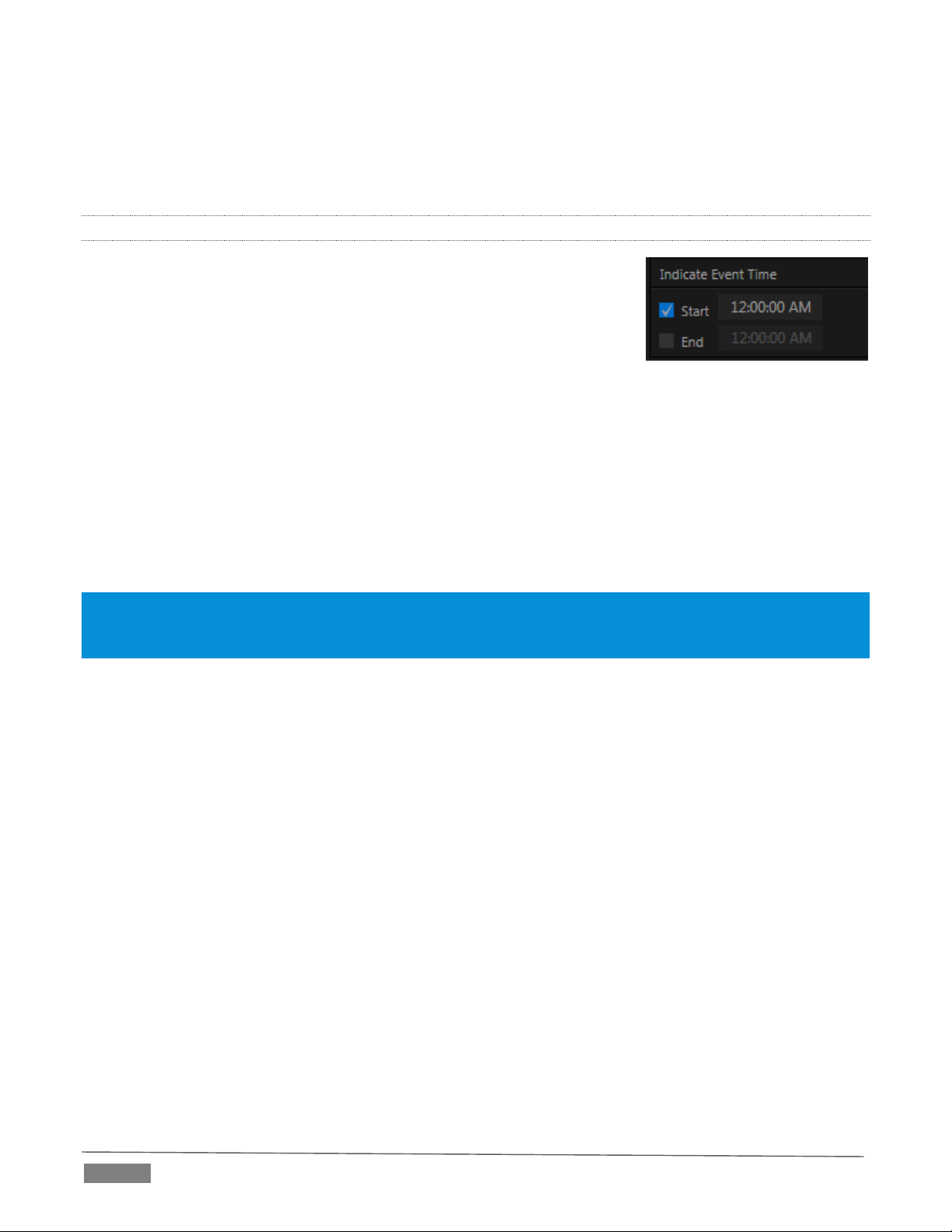
FI GUR E 86
During live production, the Dashboard and as well as TriCaster’s monitor panes and default Multiview layouts
(Figure 85) offer Broadcast Clock displays based on the current timecode.
Secondary clock displays show a useful countdown to the (production) Start and End times when the
corresponding switches are enabled in the Timecode Configuration panel.
8.4.3 LTC TIMECODE
Linear timecode is by far the most common method of sharing an external
timecode reference in video production.
Output from an external timecode generator is supplied to devices in the
video pipeline using a standard audio connection. TriCaster uses either
Audio Input 7 or 3 for this purpose (see Section 3.6), depending on the model
(as mentioned previously, TriCaster 410 and TriCaster Mini do not support
this feature).
TriCaster decodes time stamps from the audible signal, and uses the values for clock displays and embedded
timecode when recording video. This is a great asset for post-production purposes. Enable linear timecode
using the switch labeled Use External timecode (LTC) in Timecode Configuration.
Sound from the audio input tasked with supplying timecode is automatically muted for recording and output
purposes when LTC timecode is enabled, but you can un-mute it briefly in the Audio Mixer to let you adjust
input levels.
Hint: The timecode display in the Live Desktop titlebar is tinted blue when external timecode is in use. If the external
connection is lost for any reason, the display changes to white. TriCaster will attempt to maintain continuous
timecode from the interruption on, until a valid signal is restored (in which case the display turns blue once more).
Page | 88
 Loading...