

Page 1
ProSafe Wireless-N
Access Point WNAP210
Reference Manual
NETGEAR, Inc.
350 East Plumeria Drive
San Jose, CA 95134 USA
202-10474-01
March 2009
v1.0
Page 2

© 2009 by NETGEAR, Inc. All rights reserved..
Technical Support
Please refer to the support information card that shipped with your product. By registering your product at
http://www.netgear.com/register, we can provide you with faster expert technical support and timely notices of product
and software upgrades.
NETGEAR, INC. Support Information
Phone: 1-888-NETGEAR, for US & Canada only. For other countries, see your Support information card.
E-mail: support@netgear.com
North American NETGEAR website: http://www.netgear.com
Trademarks
NETGEAR, the NETGEAR logo, ProSafe, and Auto Uplink are trademarks or registered trademarks of NETGEAR, Inc.
Microsoft, Windows, Windows NT and Vista are registered trademarks of Micros oft Corporation.Other brand and
product names are registered trademarks or trademarks of their respective holders.
Statement of Conditions
In the interest of improving internal design, operational function, and/or reliability, NETGEAR reserves the right to
make changes to the products described in this document without notice.
NETGEAR does not assume any liability that may occur due to the use or application of the product(s) or circuit
layout(s) described herein.
Certificate of the Manufacturer/Importer
It is hereby certified that the ProSafe Wireless-N Access Point WNAP210 has been suppressed in accordance with the
conditions set out in the BMPT-AmtsblVfg 243/1991 and Vfg 46/1992. The operation of some equipment (for example,
test transmitters) in accordance with the regulations may, however, be subject to certain restrictions. Please refer to the
notes in the operating instructions.
The Federal Office for Telecommunications Approvals has been notified of the placing of this equipment on the market
has been granted the right to test the series for compliance with the regulations.
and
Bestätigung des Herstellers/Importeurs
Es wird hiermit bestätigt, daß dasProSafe Wireless-N Access Point WNAP210 gemäß der im BMPT-AmtsblVfg 243/
1991 und Vfg 46/1992 aufgeführten Bestimmungen entstört ist. Das vorschriftsmäßige Betreiben einiger Geräte (z.B.
Testsender) kann jedoch gewissen Beschränkungen unterliegen. Lesen Sie dazu bitte die Anmerkungen in der
Betriebsanleitung.
Das Bundesamt für Zulassungen in der Telekommunikation wurde davon unterrichtet, daß dieses Gerät auf den Markt
gebracht wurde und es ist berechtigt, die Serie auf die Erfüllung der Vorschriften hin zu überprüfen.
Voluntary Control Council for Interference (VCCI) Statement
This equipment is in the Class B category (information equipment to be used in a residential area or an adjacent area
thereto) and conforms to the standards set by the Voluntary Control Council for Interference by Data Processing
Equipment and Electronic Office Machines aimed at preventing radio interference in such residential areas. When used
near a radio or TV receiver, it may become the cause of radio interference. Read instructions for correct handling.
ii
v1.0 March 2009
Page 3

Note: Delete this note and the information below for products that are not wireless.
Regulatory Compliance Information
This section includes user requirements for operating this product in accordance with National laws for usage of radio
spectrum and operation of radio devices. Failure of the end-user to comply with the applicable requirements may result
in unlawful operation and adverse action against the end-user by the applicable National regulatory authority.
NOTE: This
product's firmware limits operation to only the channels allowed in a particular Region or Country.
Therefore, all options described in this user's guide may not be available in your version of the product.
Europe – EU Declaration of Conformity
Marking by the above symbol indicates compliance with the Essential Requirements of the R&TTE Directive of the
European Union (1999/5/EC). This equipment meets the following conformance standards:
EN300 328, EN301 489-17, EN60950, EN301 893
Europe – Declaration of Conformity in Languages of the European Community
Cesky [Czech] NETGEAR Inc. tímto prohlašuje, že tento Radiolan je ve shode se základními
požadavky a dalšími príslušnými ustanoveními smernice 1999/5/ES..
Dansk
[D
anish]
Deutsch
[German]
Eesti
an]
[Estoni
English Hereby, NETGEAR Inc.,
Español
panish]
[S
Ελληνική
[Greek]
Undertegnede NETGEAR Inc. erklærer herved, at følgende udstyr Radiolan overholder
de væsentlige krav og øvrige relevante krav i direktiv 1999/5/EF.
Hiermit erklärt NETGEAR Inc., d
den grundlegenden Anforderungen und den übrigen einschlägigen Bestimmungen der
Richtlinie 1999/5/EG befindet.
Käesolevaga kinnitab NETGEAR Inc. seadme Radiolan vastavust direktiivi 1999/5/EÜ
põhinõuetele ja nimetatud direktiivist tulenevatele teistele asjakohastele sätetele.
declares that this Radiolan is in compliance with the essential
requirements and other relevant provisions of Directive 1999/5/EC.
Por medio de la presente NETGEAR Inc. declara que el Radiolan cumple con los
requisitos esenciales y cualesquiera otras disposiciones aplicables o exigibles de la
Directiva 1999/5/CE.
ΜΕ ΤΗΝ ΠΑΡΟΥΣΑ NETGEAR Inc. ΔΗΛΩΝΕΙ ΟΤΙ Radiolan ΣΥΜΜΟΡΦΩΝΕΤΑΙ
ΠΡΟΣ ΤΙΣ ΟΥΣΙΩΔΕΙΣ ΑΠΑΙΤΗΣΕΙΣ ΚΑΙ ΤΙΣ ΛΟΙΠΕΣ ΣΧΕΤΙΚΕΣ ΔΙΑΤΑΞΕΙΣ ΤΗΣ
ΟΔΗΓΙΑΣ 1999/5/ΕΚ.
ass sich das Gerät Radiolan in Übereinstimmung mit
iii
v1.0 March 2009
Page 4

Français
[French]
Italiano [Italian] Con la presente NETGEAR Inc. dichiara che questo Radiolan è conforme ai requisiti
Par la présente NETGEAR Inc. déclare que l'appareil Radiolan est conforme aux
exigences essentielles et aux autres dispositions pertinentes de la directive 1999/5/CE.
essenziali ed alle altre disposizioni pertinenti stabilite dalla direttiva 1999/5/CE.
Latviski
[Latvian]
Lietuvių
[Lithuanian]
Nederlands
[Dutch]
Malti [Maltese] Hawnhekk, NETGEAR Inc., jiddikjara li dan Radiolan jikkonforma mal-htigijiet
Magyar
[Hungarian]
Polski [Polish] Niniejszym NETGEAR Inc. oświadcza, że Radiolan jest zgodny z zasadniczymi
Português
[Portuguese]
Slovensko
[Slovenian]
Slovensky
[Slovak]
Suomi
[Finnish]
Ar šo NETGEAR Inc. deklarē, ka Radiolan atbilst Direktīvas 1999/5/EK būtiskajām
prasībām un citiem ar to saistītajiem noteikumiem.
Šiuo NETGEAR Inc. deklaruoja, kad šis Radiolan atitinka esminius reikalavimus ir kitas
1999/5/EB Direktyvos nuostatas.
Hierbij verklaart NETGEAR Inc. dat het toestel Radiolan in overeenstemming is met de
essentiële eisen en de andere relevante bepalingen van richtlijn 1999/5/EG.
essenzjali u ma provvedimenti ohrajn relevanti li hemm fid-Dirrettiva 1999/5/EC.
Alulírott, NETGEAR Inc. nyilatkozom, hogy a Radiolan megfelel a vonatkozó alapvetõ
követelményeknek és az 1999/5/EC irányelv egyéb elõírásainak.
wymogami oraz pozostałymi stosownymi postanowieniami Dyrektywy 1999/5/EC.
NETGEAR Inc. declara que este Radiolan está conforme com os requisitos essenciais
e outras disposições da Directiva 1999/5/CE.
NETGEAR Inc. izjavlja, da je ta Radiolan v skladu z bistvenimi zahtevami in ostalimi
relevantnimi določili direktive 1999/5/ES.
NETGEAR Inc. týmto vyhlasuje, _e Radiolan spĺňa základné po_iadavky a všetky
príslušné ustanovenia Smernice 1999/5/ES.
NETGEAR Inc. vakuuttaa täten että Radiolan tyyppinen laite on direktiivin 1999/5/EY
oleellisten vaatimusten ja sitä koskevien direktiivin muiden ehtojen mukainen.
Svenska
[Swedish]
Íslenska
[Icelandic]
Norsk
[Norwegian]
iv
Härmed intygar NETGEAR Inc. att denna Radiolan står I överensstämmelse med de
väsentliga egenskapskrav och övriga relevanta bestämmelser som framgår av direktiv
1999/5/EG.
Hér með lýsir NETGEAR Inc. yfir því að Radiolan er í samræmi við grunnkröfur og aðrar
kröfur, sem gerðar eru í tilskipun 1999/5/EC.
NETGEAR Inc. erklærer herved at utstyret Radiolan er i samsvar med de
grunnleggende krav og øvrige relevante krav i direktiv 1999/5/EF.
v1.0 March 2009
Page 5

FCC Requirements for Operation in the United States
FOR HOME OR OFFICE USE
Tested to Comply
with FCC Standards
PY308400098
ProSafe Wireless-N Access Point WNAP210
FCC Information to User
This product does not contain any user serviceable components and is to be used with approved antenn as only. Any
product changes or modifications will invalidate all applicable regulatory certifications and approvals
FCC Guidelines for Human Exposure
This equipment complies with FCC radiation exposure limits set forth for an uncontrolled environment. This equipment
should be installed and operated with minimum distance of 20 cm between the radiator and your body.
This transmitter must not be co-located or oper
FCC Declaration Of Conformity
We NETGEAR, Inc., 4500 Great America Parkway, Santa Clara, CA 95054, declare under our sole responsibility that
the model WNAP210 ProSafe Wireless-N Access Point WNAP210 complies with Part 15 of FCC Rules. Operation is
subject to the following two conditions:
• This device may not cause harmful interferen
• This device must accept any interference received, including interference that may cause undesired operation.
FCC Radio Frequency Interference Warnings & Instructions
This equipment has been tested and found to comply with the limits for a Class B digital device, pursuant to Part 15 of
the FCC Rules. These limits are designed to provide reasonable protection against harmful interference in a residential
installation. This equipment uses and can radiate radio frequency energy and, if not installed and used in accordance
with the instructions, may cause harmful interference to radio communications. However, there is no guarantee that
interference will not occur in a particular installation. If this equipment does cause harmful interference to radio or
television reception, which can be determined by turning the equipment off and on, the user is encouraged to try to
correct the interference by one or more of the following methods:
• Reorient or relocate the receiving antenna
• Increase the separation between
• Connect the equipment into an electrical
• Consult the dealer or an experienced radio/TV technician for help.
the equipment and the receiver
ating in conjunction with any other antenna or transmitter.
ce, and
outlet on a circuit different from that which the radio receiver is connected
Modifications made to the product, unless expressly approved by NETGEAR, Inc., could void the user's right to operate
the equipment.
v
v1.0 March 2009
Page 6

Canadian Department of Communications Radio Interference Regulations
This digital apparatus (ProSafe Wireless-N Access Point WNAP210) does not exceed the Class B limits for radio-noise
emissions from digital apparatus as set out in the Radio Interference Regulations of the Canadian Department of
Communications.
Product and Publication Details
Model Number: WNAP210
Publication Date: March 2009
Product Family: Wireless Access Point
Product Name: ProSafe Wireless-N Access Point WNAP210
Home or Business Product: Business
Language: English
Publication Part Number: 202-10474-01
Publication Version Number: 1.0
vi
v1.0 March 2009
Page 7

Contents
About This Manual
Conventions, Formats, and Scope ................................................................................... xi
How to Use This Manual ..................................................................................................xii
How to Print This Manual .................................................................................................xii
Revision History ...............................................................................................................xiii
Chapter 1
Introduction
About the ProSafe Wireless-N Access Point WNAP210 ................................................1-1
Key Features and Standards ..........................................................................................1-2
Supported Standards and Conventionss ..................................................................1-2
Key Features ............................................................................................................1-3
802.11b/g/n Standards–based Wireless Networking ................................................1-4
Autosensing Ethernet Connections with Auto Uplink ...............................................1-5
System Requirements ....................................................................................................1-6
What Is In the Box? ........................................................................................................1-6
Hardware Description .....................................................................................................1-7
Front Panel ...............................................................................................................1-7
Rear Panel ................................................................................................................1-8
Chapter 2
Installation and Configuration
Wireless Equipment Placement and Range Guidelines .................................................2-1
Understanding WNAP210 Wireless Security Options ....................................................2-2
Installing the WNAP210 Wireless Access Point .............................................................2-3
Setting up the Wireless Access Point ......................................................................2-4
Configuring Lan and Wireless Settings ....................................................................2-4
v1.0 March 2009
vii
Page 8

Configuring Your Wireless Settings ..........................................................................2-8
Deploying the Access Point ..........................................................................................2-10
Verifying Wireless Connectivity .............................................................................. 2-11
Logging In Using the Default IP Address ............................................................... 2-11
Mounting the Access Point Using the Wall Mount Kit (Optional) ..................................2-12
Configuring and Testing Your PCs for Wireless Connectivity .................................2-13
Logging in to the Access Point ...............................................................................2-14
Setting Basic IP Options ...............................................................................................2-15
Wireless Settings ..........................................................................................................2-16
Configuring 802.11b/g/n Wireless Settings ............................................................2-16
Configuring QoS Settings .......................................................................................2-20
Setting Up and Testing Basic Wireless Connectivity ....................................................2-21
Understanding Security Profiles ...................................................................................2-22
SSID and WEP/WPA Settings Setup Form ............................................................2-26
Configuring the RADIUS Server Settings ...............................................................2-27
Setting up a Security Profile ...................................................................................2-29
Configuring WEP .............................................................................................2-31
Configuring WPA with RADIUS .......................................................................2-33
Configuring WPA2 with RADIUS .....................................................................2-34
Configuring WPA and WPA2 with RADIUS .....................................................2-35
Configuring WPA-PSK .....................................................................................2-36
Configuring WPA2-PSK ...................................................................................2-37
Configuring WPA-PSK and WPA2-PSK ...........................................................2-38
Restricting Wireless Access by MAC Address .......................................................2-39
Chapter 3
Management
Remote Management .....................................................................................................3-1
Remote Console .............................................................................................................3-2
Manage Using Telnet ...............................................................................................3-3
Upgrading the Wireless Access Point Software .............................................................3-4
Configuration File Management .....................................................................................3-5
Saving the Configuration ..........................................................................................3-6
Restoring the Configuration ......................................................................................3-8
Restoring the WNAP210 to the Factory Default Settings ...............................................3-8
viii
v1.0 March 2009
Page 9

Changing the Administrator Password ...........................................................................3-9
Enabling the SysLog Server .........................................................................................3-10
Using Activity Log Information ...................................................................................... 3-11
Viewing General Summary Information ........................................................................3-12
Viewing Network Traffic Statistics .................................................................................3-14
Viewing Available Wireless Station Statistics ................................................................3-16
Enabling Rogue AP Detection ......................................................................................3-17
Importing a Rogue AP List from a File ...................................................................3-18
Viewing and Saving AP Lists ........................................................................................3-19
Viewing AP Lists ....................................................................................................3-19
Creating AP Lists Manually ....................................................................................3-21
Chapter 4
Advanced Configuration
802.1Q VLAN .................................................................................................................4-1
Hotspot Settings .............................................................................................................4-3
Configuring Advanced Wireless Settings .......................................................................4-4
Configuring Advanced QoS Settings ..............................................................................4-6
Enabling Wireless Bridging and Repeating ....................................................................4-8
Configuring a WNAP210 as a Point-to-Point Bridge .............................................. 4-11
Configuring a Point-to-Multi-Point Wireless Bridge ................................................4-13
Configuring the WNAP210 as a Wireless Repeater ...............................................4-15
Configuring the WNAP210 for Client Mode ........................................................... 4-16
Chapter 5
Troubleshooting and Debugging
No lights are lit on the wireless access point ..................................................................5-1
The Wireless LAN activity light does not light up ............................................................5-2
The LAN light is not lit .....................................................................................................5-2
I cannot access the Internet or the LAN with a wireless capable computer ...................5-2
I cannot connect to the WNAP210 to configure lit ..........................................................5-3
When I enter a URL or IP address I get a timeout error .................................................5-3
Using the Reset Button to Restore Factory Default Settings ..........................................5-4
v1.0 March 2009
ix
Page 10

Appendix A
Default Settings and Technical Specifications
Factory Default Settings ................................................................................................ A-1
Technical Specifications ................................................................................................. A-3
Appendix B
Related Documents
Appendix C
Command Sets
Index
x
v1.0 March 2009
Page 11
About This Manual
The NETGEAR® Pr oSafe™ Wireless-N Access Point WNAP210 Refer ence Manual describes how
to install, configure and troubleshoot the ProSafe Wirele ss Access Point WNAP210. The
information in this manual is intended for readers with intermediate computer and Internet skills.
Conventions, Formats, and Scope
The conventions, formats, and scope of this manual are described in the following paragraphs:
• T
ypographical Conventions. This manual uses the following typographical conventions::
Italic Emphasis, books, CDs, file and server names, extensions
Bold User input, IP addresses, GUI screen text
Fixed Command prompt, CLI text, code
italic URL links
• Formats. This manual uses the following formats to highlight special messages:
Note: This format is used to highlight information of importance or special interest.
Tip: This format is used to highlight a procedure that will save time or resources.
Warning: Ignoring this type of note may result in a malfunction or damage to the
equipment.
v1.0 March 2009
xi
Page 12
ProSafe Wireless-N Access Point WNAP210 Reference Manual
Danger: This is a safety warning. Failure to take heed of this notice may result in
personal injury or death.
• Scope. This manual is written for the WNAP210 Wireless Access Point according to these
specifications:
Product Version Version 1.0
Manual Publication Date March 2009
For more information about network, Internet, firewall, and VPN technologies, see the links to the
NETGEAR website in Appendix B, “Related Documents”
Note: Product updates are available on the NETGEAR, Inc. website at
http://kbserver.netgear.com/main.asp.
.
How to Use This Manual
The HTML version of this manual includes the following:
• Buttons,
at a time.
•A
Double-click a link in the table of contents or index
described in the manual.
•A
model.
• Links to PDF versions of the full manual
and , for browsing forward or backward through the manual one pa ge
button that displays the table of contents and a button that displays an index.
to navigate directly to where the topic is
button to access the full NETGEAR, Inc. online knowledge base for the product
and individual chapters.
How to Print This Manual
To print this manual, you can choose one of the following options, according to your needs.
• Printing a page from HTML. Each page in the HTML version of the manual is dedicated to
a major topic. Select File > Print from the browser menu to print the page contents.
xii About This Manual
v1.0 March 2009
Page 13

ProSafe Wireless-N Access Point WNAP210 Reference Manual
• Printing from PDF. Your computer must have the free Adobe Acrobat reader installed in
order to view and print PDF files. The Acrobat reader is available on the Adobe Web site at
http://www.adobe.com.
– Printing a PDF chapter. Use the PDF
of This Chapter link at the top left corner of any
page.
• Click the PDF of This Chapter li
you want to print. The PDF version of the chapter you were viewing opens in a
browser window.
• Click the print icon in the upper left of your browser window.
– Printin
g a PDF version of the complete manual. Use the Complete PDF Manual link
at the top left corner of any page.
• Click the Complete PDF
The PDF version of the complete manual opens in a browser window.
• Click the print icon in the upper left corn
Tip: If your printer supports printing two pages on a single sheet of paper, you can
save paper and printer ink by selecting this feature.
Revision History
Part Number
Version
Number
nk at the top left corner of any page in the chapter
Manual link at the top left corner of any page in the manual.
er of your browser window.
Date Description
202-10474-01 1.0 March
200
9
About This Manual xiii
Initial edition: New product
v1.0 March 2009
Page 14

ProSafe Wireless-N Access Point WNAP210 Reference Manual
xiv About This Manual
v1.0 March 2009
Page 15

Chapter 1
Introduction
This chapter describes some of the key features of the NETGEAR ProSafe Wireless-N Access
Point WNAP210. It also includes the minimum prerequisites for installation (
Requirements” on page 1-5), package contents (“What Is In the Box?” on page 1-5), and a
description of the front and back panels of the WNAP210 (“Hardware Description” on page 1-6).
About the ProSafe Wireless-N Access Point WNAP210
The ProSafe Wireless-N Access Point WNAP210 is the basic building block of a wireless LAN
infrastructure. It provides connectivity between Ethernet wired networks and radio-equipped
wireless notebook systems, desktop systems, print servers, and other devices.
The access point provides wireless connectivity to multiple wireless network devices within a
fixed range or area of coverage—interacting with a wireless network interface card (NIC) through
an antenna. T y pically, an individual in-building access point provides a maximum connectivity
area of about a 500 foot radius. Consequently, the ProSafe Wireless-N Access Point WNAP210
can support a small group of users in a range of several hundred feet. Most access points can
handle between 10 to 30 users simultaneously.
“System
The ProSafe Wireless-N Access Point WNAP210 acts as a bridge between the wired LAN and
wireless clients. Connecting multiple WNAP210 Wireless-N Access Points through a wired
Ethernet backbone can further increase the wireless network coverage. As a mobile computing
device moves out of the range of one access point, it moves into the range of another. As a result,
wireless clients can freely roam from one access point to another and still maintain seamless
connection to the network.
The auto-sensing capability of the ProSafe Wireless-N Access Point WNAP210 allows packet
transmission at up to 300 Mbps, or at reduced speeds to compensate for distance or
electromagnetic interference.
1-1
v1.0 March 2009
Page 16

ProSafe Wireless-N Access Point WNAP210 Reference Manual
Key Features and Standards
The WNAP210 Wireless-N Access Point is easy to use and provides solid wireless and networking
support. It also offers a wide range of security options.
Supported Standards and Conventions
The following standards and conventions are supported:
• Standards Compliance. The wireless access point complies with the IEEE 802.11 b/g
standards for wireless LANs, and is WiFi certified for 802.11n draft 2.0 standard.
• Full WPA and WPA2 support. The wireless access point provides WPA and WPA2
enterprise-class strong security with RADIUS and certificate authentication as well as
dynamic encryption key generation. The WPA-PSK and WPA2-PSK preshared key
authentication is without the overhead of RADIUS servers but with all of the strong security of
WPA.
• Multiple BSSIDs. The access point supports multiple BSSIDs. When a wireless access point
is connected to a wired network and a set of wireless stations, it is called a Basic Service Set
(BSS). The Basic Service Set Identifier (BSSID) is a unique identifier attached to the header of
packets sent over a WLAN that differentiates one WLAN from another when a mobile device
tries to connect to the network.
The multiple BSSID feature allows you to configure up to eight SSIDs per radio mode on your
access point and assign different configuration settings to each SSID. All the configured
SSIDs are active, and the network devices can connect to the access point by using any of
these SSIDs.
• DHCP client support. DHCP provides a dynamic IP address to PCs and other devices upon
request. The access point can act as a client and obtain information from your DHCP server; it
can also act as a DHCP server and provide network information for wireless clients.
• SNMP Support. Support for Simple Network Management Protocol (SNMP) Management
Information Base (MIB) management.
• 802.1Q VLAN (virtual LAN) support. A network of computers that behave as if they are
connected to the same network even though they might actually be physically located on
different segments of a LAN. VLANs are configured through software rather than hardware,
which makes them extremely flexible. VLANs are very useful for user and host management,
bandwidth allocation, and resource optimization.
1-2 Introduction
v1.0 March 2009
Page 17

ProSafe Wireless-N Access Point WNAP210 Reference Manual
Key Features
The WNAP210 Access Point provides solid functionality, including the following features:
• Multiple operating modes:
– Wireless Access Point. Operates as a standard 802.11b/g/n access point.
– Point-to-Point Bridge. In this mode, the access point communicates only with another
bridge-mode wireless station or access point. Network authentication should be used to
protect this communication.
– Point-to-Multi-Point Bridge. Select this only if this access point is the “master” for a
group of bridge-mode wireless stations. The other bridge-mode wireless stations send all
traffic to this master, and do not communicate directly with each other. Network
authentication should be used to protect this traffic.
– Wireless Repeater. In this mode, the access point does not function as an access point. It
communicates only with Repeater mode, Point-to-Point Bridge mode, and Point-to-Multipoint-bridge-mode wireless stations. Network authentication should be used to protect this
communication.
• Hotspot settings. You can allow all HTTP (TCP, port 80) requests to be captured and
redirected to the URL you specify.
• Upgradeable firmware. Firmware is stored in a flash memory, you can upgrade it easily,
using only your Web browser, and you can upgrade it remotely. You can also use the
command-line interface.
• Rogue AP detection. The Rogue AP filtering feature ensures that unknown APs are not given
access to any part of the LAN.
• Access Control. The Access Control MAC address filtering feature can ensure that only
trusted wireless stations can use the access point to gain access to your LAN.
• Security profiles. When using multiple BSSIDs, you can configure unique security settings
(encryption, SSID, and so on) for each BSSID.
• Hidden mode. The SSID is not broadcast, assuring only clients configured with the correct
SSID can connect.
• Configuration backup. Configuration settings can be backed up to a file and restored.
• Secure and economical operation. Adjustable power output allows more secure or
economical operation.
• Power over Ethernet. Power can be supplied to the access point over the Ethernet port from
any 802.3af-compliant mid-span or end-span source.
Introduction 1-3
v1.0 March 2009
Page 18

ProSafe Wireless-N Access Point WNAP210 Reference Manual
• Autosensing Ethernet connection with Auto Uplink™ interface. Connects to 10/100/1000
Mbps IEEE 802.3 Ethernet networks.
• LED indicators. Power, Test, LAN speed, LAN activity, and wireless activity for each radio
mode are easily identified.
• Wireless Multimedia (WMM) support. WMM is a subset of the 802.11e standard. WMM
allows wireless traffic to have a range of priorities, depending on the kind of data. Timedependent information, like video or audio, has a higher priority than normal traffic. For
WMM to function correctly, wireless clients must also support WMM.
• Quality of Service (QoS) Support. You can configure parameters that affect traffic flowing
from the wireless access point to the client station and traffic flowing from the client station to
the wireless access point. The QoS feature allows you to prioritize traffic, such as voice and
video traffic, so that packets do not get dropped.
• VLAN security profiles. Each security profile is automatically allocated a VLAN ID when
the security profile is modified.
802.11b/g/n Standards–based Wireless Networking
The ProSafe Wireless-N Access Point WNAP210 provides a bridge between Ethernet wired LANs
and 802.11b/g and 802.11 draft n–compatible wireless LAN networks. It provides co nn ectiv ity
between Ethernet wired networks and radio-equipped wireless notebook systems, desktop
systems, print servers, and other devices. Additionally, the access point supports the following
wireless features:
• Aggregation support
• Reduced InterFrame spacing support
• Multiple input, multiple output (MIMO) support
• Distributed coordinated function (CSMA/CA, back-off procedure, ACK procedure,
retransmission of unacknowledged frames)
• RTS/CTS handshake
• Beacon generation
• Packet fragmentation and reassembly
• Auto or long preamble
• Roaming among access points on the same subnet
Autosensing Ethernet Connections with Auto Uplink
The access point can connect to a standard Ethernet network. The LAN interface is autosensing
and capable of full-duplex or half-duplex operation.
1-4 Introduction
v1.0 March 2009
Page 19

ProSafe Wireless-N Access Point WNAP210 Reference Manual
The wireless access point incorporates Auto UplinkTM technology . The Ethernet port automatically
senses whether the Ethernet cable plugged in to the port should have a “normal” connection such
as to a computer or an “uplink” connection such as to a switch or hub. That port then configures
itself correctly. This feature also eliminates any concerns about crossover cables, as Auto Uplink
accommodates either type of cable to make the right connection.
System Requirements
Before installing the access point, make sure that your system meets these requirements:
• A 10/100/1000 Mbps local area network device such as a hub or switch
• The Category 5 UTP straight-through Ethernet cable with RJ-45 connector included in the
package, or one like it
• A 100–120 V, 50–60 Hz AC power sourc e
• A Web browser for configuration such as Microsoft Internet Explorer 5.0 or later, or Mozilla
3.0 or later
• At least one computer with the TCP/IP protocol installed
• 802.11b/g- or 802.11b/g-compliant devices, such as the NETGEAR WG511 Wireless Adapter
What Is In the Box?
The product package should contain the following items:
• ProSafe Wireless-N Access Point WNAP210
• Power adapter and cord (12Vdc, 1.0A)
• Straight-through Category 5 Ethernet cable
• NETGEAR WNAP210 Wireless-N Access Point Installation Guide
• Resource CD, which includes this manual
• Vertical stand feet (2)
• Wall mount kit made up of brackets (2) and hardware
Contact your reseller or customer support in your area if there are any missing or damaged parts.
Refer to the for the the NETGEAR, Inc., website at
telephone number of customer support in your area. You should keep the Installation Guide, along
with the original packing materials, and use the packing materials to repack the access point if you
Introduction 1-5
v1.0 March 2009
http://kbserver.netgear.com/main.asp for the
Page 20
ProSafe Wireless-N Access Point WNAP210 Reference Manual
1
2
3
4
need to return it for repair. To qualify for product updates and product warranty, NETGEAR
encourages you to register on the NETGEAR Web site at http://my.netgear.com/registration/
login.aspx.
Hardware Description
This section describes the front and rear hardware functions of the access point.
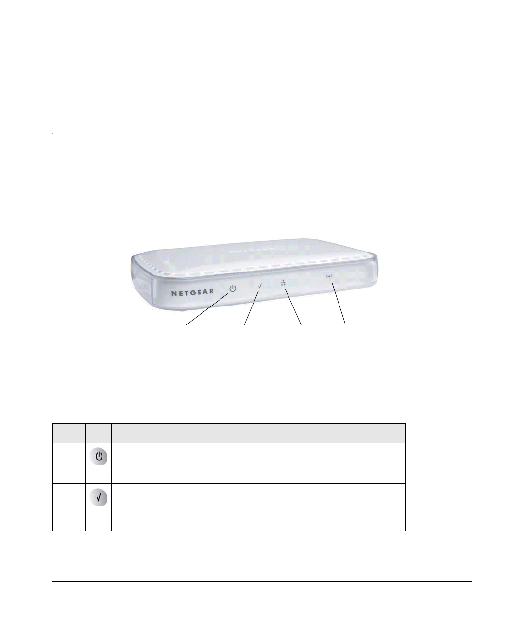
Front Panel
The WNAP210 front hardware functions are described in the following figure and table.
Figure 1-1
The following table explains the LED:
Table 1-1. Front Panel LEDs
Item LED DESCRIPTION
1 Power
Off. Power is off.
On. Power is on.
2
1-6 Introduction
Te st
Blinking. The device is running a self-test or is loading software. This
ED may blink for a minute before going off. If it continues to
L
blink, it indicates a system fault.
v1.0 March 2009
Page 21
ProSafe Wireless-N Access Point WNAP210 Reference Manual
1
32
Table 1-1. Front Panel LEDs (continued)
Item LED DESCRIPTION
3 Ethernet LAN Speed
Off. A 10 Mbps or no link detected.
Amber. A 10/100 Mbps link detected.
Green. A 1000 Mbps link detected.
4 WLAN
Blinking (Blue). Indicates Wireless activity has been detected.
Rear Panel
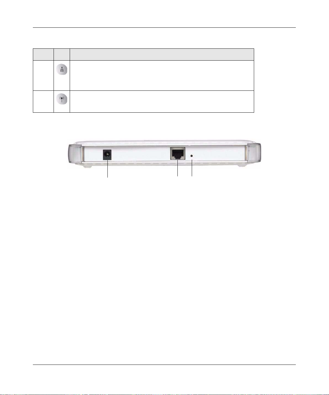
Figure 1-2
The access pointrear panel functions are described in the following list:
1. Power socket. This socket connects to the WNAP210 12V 1.0A power adapter
2. RJ-45 Ethernet port. Use the WNAP210 Ethernet RJ-45 port to connect to a
.
n Ethernet LAN
through a device such as a hub, switch, router, or PoE switch.
3. Restore factory settings button. The restore to sett
ings button restores the access point to the
factory default settings.
Introduction 1-7
v1.0 March 2009
Page 22

ProSafe Wireless-N Access Point WNAP210 Reference Manual
1-8 Introduction
v1.0 March 2009
Page 23

Chapter 2
Installation and Configuration
This chapter describes how to set up your ProSafe Wireless-N Access Point for wireless
connectivity to your LAN. This basic configuration will enable computers with 802.11b/g/n
wireless adapters to connect to the Internet, or access printers and files on your LAN.
Note: Indoors, computers can connect over 802.11b/g/n wireless networks at ranges of
several hundred feet or more. This distance allows others outside your area to
access your network. It is important to take appropriate steps to secure your
network from unauthorized access. The access point provides highly effective
security features, which are covered in detail in “Understanding WNAP210
Wireless Security Options” on page 2-2. Deploy the security features appropriate
to your needs.
You need to prepare these three things before you ca
access point:
• A location for the WNAP
“Wireless Equipment Placement and Range Guidelines” on page 2-1.
• The wireless access point connected to your LAN through a device such
router, or cable/DSL gateway.
• One or more computers with correctly config
210 that conforms to the guidelines in the following section,
n establish a connection through your wireless
as a hub, switch,
ured 802.11b/g/n wireless adapters.
Wireless Equipment Placement and Range Guidelines
The operating distance or range of your wireless connection can vary significantly based on the
physical placement of the wireless access point. The latency, data throughput performance, and
notebook power consumption of wireless adapters also vary depending on your configuration
choices.
v1.0 March 2009
2-1
Page 24

ProSafe Wireless-N Access Point WNAP210 Reference Manual
Note: Failure to follow these guidelines can result in significant performance degradation
or inability to wirelessly connect to the access point. For complete performance
specifications, see Appendix A, “Default Settings and Technical Specifications.”
For best results, place your wireless access point:
• Near the center of the area in which your PCs will operate.
• In an elevated location such as a high shelf where the wirelessly connected PCs have line-ofsight access (even if through walls).
• Away from sources of interference, such as PCs, microwaves, and 2.4 GHz cordless phones.
• Away from large metal surfaces.
A wall mount kit is provided with your wireless access point. For installation instructions, see
“Mounting the Access Point Using the Wall Mount Kit (Optional)” on page 2-12.
If using multiple access points, it is better if adjacent access points use different radio frequency
channels to reduce interference. The recommended channel spacing between adjacent access
points is five channels (for example, use channels 1 and 6, or 6 and 11).
The time it takes to establish a wireless connection can vary depending on both your security
settings and placement. Some types of security connections can take slightly longer to establish
and can consume more battery power on a notebo ok computer.
Understanding WNAP210 Wireless Security Options
Anyone wih a compatible wireless adapter can recieve your wireless data transmissions well
beyond your walls. For this reason, use the security features of your wireless equipment. The
access point provides highly effective security features, which are covered in detail in this chapter.
Deploy the security features appropriate to your needs.
2-2 Installation and Configuration
v1.0 March 2009
Page 25

ProSafe Wireless-N Access Point WNAP210 Reference Manual
Figure 2-1
There are several ways you can enhance the security of your wireless network:
• Res
trict access based on MAC address. You can restrict access to only trusted PCs so that
unknown PCs cannot wirelessly connect to the access point. MAC address filtering adds an
obstacle against unwanted access to your network, but the data broadcast over the wireless link
is fully exposed.
urn off the broadcast of the wireless network name (SSID). If you disable broadcast of the
• T
SSID, only devices that have the correct SSID can connect. This nullifies the wireless network
“discovery” feature of some products such as Windows XP, but the data is still fully exposed
to a determined snoop using specialized test equipment like wireless sniffers.
• Use WE
P. Wired Equivalent Privacy (WEP) data encryption provides data security. WEP
open authentication and WEP data encryption will block all but the most determined
eavesdropper.
• Use
WPA or WPA-PSK. Wi-Fi Protected Access (WPA) data encryption provides data
security. The very strong authentication along with dynamic per frame rekeying of WPA make
it virtually impossible to compromise. Because this is a new standard, wireless device driver
and software availability might be limited.
Note: WEP and TKIP provide only legacy (slower) rates of operation. AES
encryption is recommended in order to use the 11n rates and speed. See
Table 2-1 on page 2-23.
Installation and Configuration 2-3
v1.0 March 2009
Page 26

ProSafe Wireless-N Access Point WNAP210 Reference Manual
Installing the WNAP210 Wireless Access Point
Before installing the ProSafe Wireless-N Access Point, you should make sure that your Ethernet
network is up and working. You will be connecting the access point to the Ethernet network so that
computers with 802.11b/g/n wireless adapters will be able to communicate with computers on the
Ethernet network. For this to work correctly , you should verify that you have met all of the system
requirements, shown in “System Requirements” on page 1-5.
Setting Up the Wireless Access Point
Tip: Before mounting the access point in a high location, set up and test the access point
to verify wireless network connectivity.
To set up the access point:
1. Prepa
2. T
3. Connect an Ethernet cable from the ac
4. Connect the
re a computer with an Ethernet adapter. If this computer i s already part o f yo ur network,
record its TCP/IP settings.
urn on your computer and configure it with a static IP address of 192.168.0.210 and a subnet
mask of 255.255.255.0.
cess point to the computer.
power adapter to the access point, and verify the following:
• The Power LED goes on.
• The Ethernet LAN LED is lit when connected to
• The WLAN LED is blinking.
a powered-on computer.
Configuring Lan and Wireless Settings
To configure the access point for LAN access:
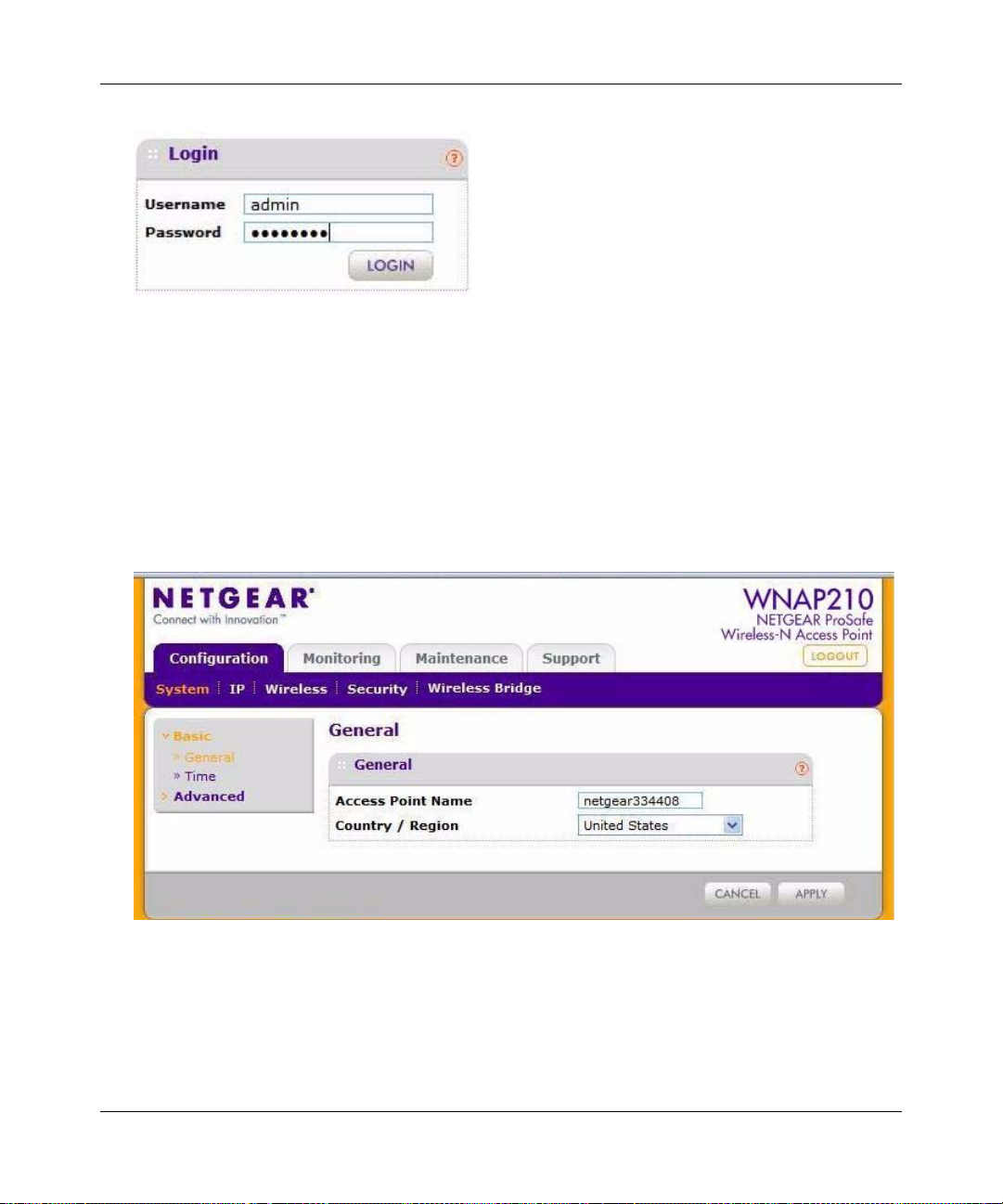
1. Connect to the acc
192.168.0.236 in the address field. The access pointlogin screen displays.
2. Enter adm
in for the user name and password for the password, both in lower case letters.
ess point by opening a browser window on your PC and entering http://
2-4 Installation and Configuration
v1.0 March 2009
Page 27
ProSafe Wireless-N Access Point WNAP210 Reference Manual
Figure 2-2
3. Login. The general screen of the the access point displays as shown in Figure 2-3. The default
settings should be suitable for most users and environments.
• When the wireless access point is connected to the Inte
rnet, you can select the
Documentation link under the Web Support menu to view the documentation for the
wireless access point.
• Select LOGOUT to exit
the access point setup screens. (You a rel automatically logged
out of the wireless access point after 5 minutes of no activity.)
Figure 2-3
4. Enter the access point name of the WNAP210.
Installation and Configuration 2-5
v1.0 March 2009
Page 28
ProSafe Wireless-N Access Point WNAP210 Reference Manual
This unique name is the access point NetBIOS name. The access point name is printed on the
rear label of the access point. The default is netgearxxxxxx, where xxxxxxx represents the last
6 digits of the access point MAC address. You can replace the default name with a unique
name up to 15 characters long.
5. From the Countr
y/Region drop-down menu, select the region where the access point will be
used (the Country/Region is not Configurable in the United States; but is configurable in the
rest of the world). Click Apply.
Note: If your country or region is not listed, please check with NETGEAR Support.
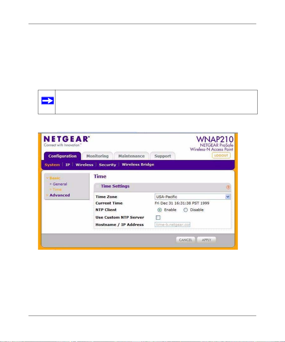
6. Select System > Basic > Time.
Figure 2-4
• Time Zone. From the drop-down list, select the local time zone for your wireless access
point from a list of all available time zones. The default is USA-Pacific. The wireless
access point will get the current time from the connecting PC.
2-6 Installation and Configuration
v1.0 March 2009
Page 29
ProSafe Wireless-N Access Point WNAP210 Reference Manual
• NTP Client. Enable the NTP client to synchronize the time of the access point with an
NTP server. The default is Enable.
Note: You must have a n Inte rnet connection to get the current time using an NTP
client.
– Use Custom NTP Server. Select this check box if you have a custom NTP server. The
default is not selected.
– Hostname / IP Addr
ess. Enter the host name or the IP address of the custom NTP server.
The default is time-b.netgear.com.
7. Click Ap
ply.
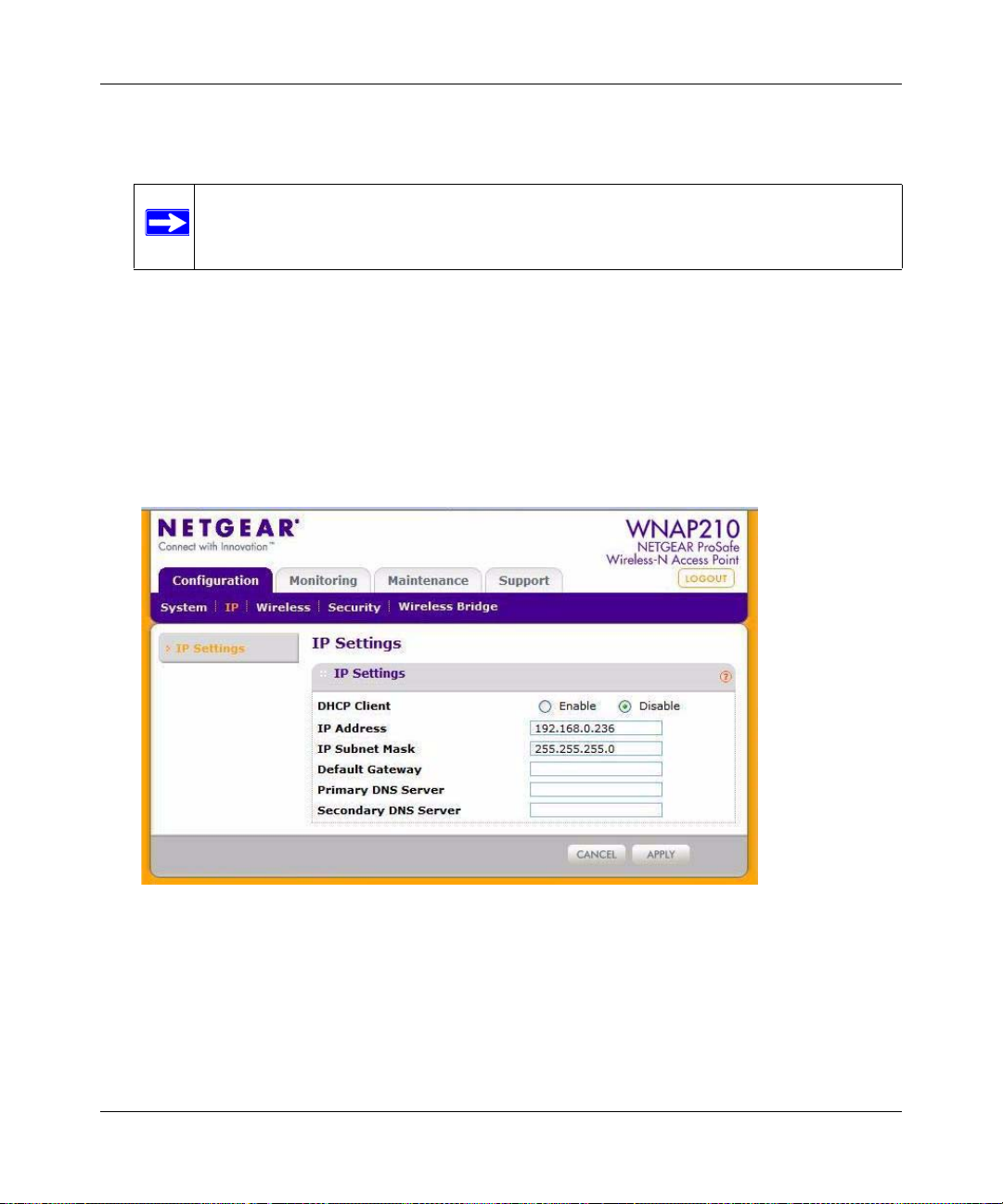
8. Select Configuration > IP to display IP
Settings.
Figure 2-5
9. Fill in the IP address fields of the access point. (See the online help for more information about
how to specify the settings on this screen).
Installation and Configuration 2-7
v1.0 March 2009
Page 30
ProSafe Wireless-N Access Point WNAP210 Reference Manual
• DHCP Client. By default, the Dynamic Host Configuration Protocol (DHCP) client is
disabled. If you have a DHCP server on your LAN and you enable DHCP, the wireless
access point will get its IP address, subnet mask, and default gateway settings
automatically from the DHCP server on your network when you connect the access point
to your LAN.
• IP Addr
ess. Enter the IP Address of your wireless access point.The default IP address is
192.168.0.236. To change it, enter an unused IP address from the address range used on
your LAN; or enable DHCP.
• IP Su
bnet Mask. The Access Point will automatically calculate the subnet mask based on
the IP address that you assign. Otherwise, you can use 255.255.255.0 (the default) as the
subnet mask.
• Default Gateway
. Enter the IP address of the gateway for your LAN. For more complex
networks, enter the address of the router for the network segment to which the wireless
access point is connected. The default is 0.0.0.0.
• Primary DNS Se
rvers. The access point will use this IP address as the primary Domain
Name Server used by stations on your LAN. The default is 0.0.0.0.
• Secondary DNS Se
rvers. The access point will use this IP address as the secondary
Domain Name Server used by stations on your LAN. The default is 0.0.0.0.
10. Click Ap
ply to save your Basic IP settings.
Note: If you change the default subnet of the LAN IP address, you will be
disconnected from the access point user interface. To reconnect, reconfigure
your computer with a static IP address within the new LAN IP subnet.
By default, the access point is set with the DHCP client
disabled. If your network uses dynamic IP
addresses, you must change this setting (see “Logging In to the Access Point” on page 2-14),
Configuring Your Wireless Settings
The following sections describe how to configure the wireless settings for 802.11b/g/n operation.
To configure the access point wireless settings:
1. Select Configuration > W
6.
2-8 Installation and Configuration
ireless.The Wireless Settings screen displays as shown in Figure 2-
v1.0 March 2009
Page 31

ProSafe Wireless-N Access Point WNAP210 Reference Manual
.
Figure 2-6
2. Configure the Wireless LAN settings based on the following field descriptions:
ireless Mode. Select the wireless operating mode you want to use:
• W
– 11b. 802.11b wireless stations only.
–
11bg. Both 802.11b and 802.11g wireless stations can be used.
– 11ng. Both 802.11n, and 802.11g wireless stations can be used.
The default is 11ng.
• Tu
rn Radio On. On by default, you can also turn off the radio to disable access through
this device. This can be helpful for configuration, network tuning, or troubleshooting
activities.
Installation and Configuration 2-9
v1.0 March 2009
Page 32

ProSafe Wireless-N Access Point WNAP210 Reference Manual
• Wireless Network Name (SSID). Enter a 32-character (maximum) service set ID in this
field; the characters are case-sensitive. When the wireless access point is deployed in
“infrastructure” mode, the SSID assigned to a wireless device must match the wireless
access point SSID for the wireless device to communicate with the access point. If they do
not match, you will not get a wireless connection to the access point. The default is
NETGEAR.
• Br
• Channel/Fr
3. Click Ap
oadcast Wireless Network Name (SSID). If Yes, the access point broadcasts its SSID
allowing wireless stations which have a “null” (blank) SSID to adopt the correct SSID. If
set to No, the SSID is not broadcast. The default is Yes.
equency. From the drop-down list, select the channel you wish to use on your
wireless LAN. The wireless channels to use in the United States. and Canada are 1 to 11;
for Europe and Australia, 1 to 13. The default is Auto.
It should not be necessary to change the wireles
interference (shown by lost connections or slow data transfers). Should this happen, you
might want to experiment with different channels to see which is the best. See the article
“Wireless Networking Basics” available on the NETGEAR website. (A link to this article
and other articles of interest can be found in Appendix B, “Related Documents.”)
ply to save your wireless settings.
s channel unless you experience
Deploying the Access Point
Now that you have completed the setup steps, you can deploy the access point in your network. If
necessary, you can now reconfigure the computer you used in Step1 “Installing the WNAP210
Wireless Access Point” on page 2-4.
Tip: Before mounting the WNAP210 in a high location, first set up and test the
WNAP210 to verify wireless network connectivity.
To deploy the access point:
1. Disconnect the
location is elevated, such as on a wall or ceiling or on the top of a cubicle, at the center of your
wireless coverage area, and within line of sight of all the mobile devices.
2-10 Installation and Configuration
access point from the PC, and position it where it will be deployed. The best
v1.0 March 2009
Page 33

ProSafe Wireless-N Access Point WNAP210 Reference Manual
2. Connect an Ethernet cable from your access point to a LAN port on your router, switch, or
hub.
Note: By default, access point is set with the DHCP client disabled. If your network
uses dynamic IP addresses, you must change this setting. To connect to the
access point after the DHCP server on your network assigns it a new IP
address, enter the wireless access point name in your W eb browser. The default
wireless access point name is netgearxxxxxx, where xxxxxx represents the
last 6 bytes of the MAC address. The default name is printed on the bottom
label of the access point.
3. If you are not using PoE, connect the power adapter to the wireless access point, and plug the
power adapter into a power outlet. The Power and LAN LEDs should be on, and the WLAN
LED should blink.
Verifying Wireless Connectivity
Follow the instructions in the next sections to set up and test basic wireless connectivity. Once you
have established basic wireless connectivity, you can enable security settings appropriate to your
needs (see “Understanding WNAP210 Wireless Security Options” on page 2-2).
The default SSID for the 802.11b/g/n is NETGEAR_11ng. The SSID of any wireless access
adapte
rs must match the SSID configured in the ProSafe Wireless-N Access Point. If they do not
match, no wireless connection will be made.
Note: If you are unable to connect, see Chapter 5, “Troubleshooting and Debugging.”
Logging In Using the Default IP Address
After you install the access point, log in to the wireless access point to configure the basic settings
and the wireless settings. The access point is set, by default, with the IP address of 192.168.0.236
with DHCP disabled.
Note: The computer you are using to connect to the access point should be configured
with an IP address that starts with 192.168.0.x and a subnet mask of 255 .255.255.0.
Installation and Configuration 2-11
v1.0 March 2009
Page 34

ProSafe Wireless-N Access Point WNAP210 Reference Manual
To log in using the default IP Address:
1. Open a
Connect to the access point by entering its default address of http://
browser. Your Web browser should automatically find the access point and display the home
screen.
2. Enter adm
use a new LAN address and password if you have set them up.
3. Click Lo
4. Select Conf
the correct (default) channel has been selected for your network.
It should not be necessary to change the wireles
problems or are near another wireless access point. Select a channel that is not being used by
any other wireless networks within several hundred feet of your wireless access point.
5. Click Ap
Web browser such as Internet Explorer, Mozilla Firefox, or Netscape Navigator.
192.168.0.236 into your
in for the user name and password for the password, both in lower case letters or
gin.
iguration > Wireless. Verify your operating mode, 1 1b , 1 1 bg, or 11ng. Verify that
s channel unless you notice interference
ply to save any changes.
Mounting the Access Point Using the Wall Mount Kit
(Optional)
Tip: Before mounting the access point in a high location, first set up and test the access
point to verify wireless network connectivity.
To install the wireless access point mounting brackets:
1. Disconnect
elevated, such as on a wall or ceiling or the top of a cubicle, at the center of your wireless
coverage area, and within line of sight of all the mobile devices (see Figure 2-7 on page 2-13).
2. Use the paper template provided to determine the location for the mounting holes. Drill holes
3/8 in. (~ 9 mm) and 13/16 in. (~20 mm) deep. The holes should be 10 1/4 in. ( 26 cm) appart,
as shown in (A). Then tap in the anchors as shown in (B).
3. The
2-12 Installation and Configuration
tabs at the center of each of the brackets hook into the center vent slots on the bottom of
the access point. The tabs on the ends of the brackets hook into the corner vent slots on the top
of the access point. Hook the center tabs of one bracket in first. Then gently snap the tabs at
the ends of the bracket into the top vents as shown in (C). Repeat for the second bracket.
the access point and position it where it will be deployed. The best location is
v1.0 March 2009
Page 35

ProSafe Wireless-N Access Point WNAP210 Reference Manual
4. Attach the brackets to the anchors using the screws from the mounting kit as shown in (D).
Figure 2-7
5. Connect an Ethernet cable from your access point to a LAN port on your router, switch, or
hub. If power is not provided by PoE, connect the power adapter to the wireless access point
and plug the power adapter into a power outlet. The Power, LAN, an d Wireless LAN LEDs
should light up.
Configuring and Testing Your PCs for Wireless Connectivity
Program the wireless adapter of your PCs to have the same SSID and channel that you configured
in the Wireless Settings for the access point. Check that they have a wireless link and are able to
obtain an IP address by DHCP from the access point.
Note: If you are configuring the access point from a wireless computer and you change
the SSID, channel, or security profile settings, you will lose your wireless
connection when you click Apply. You must then change the wireless settings of
your computer to match the new settings.
Once your PCs have basic wireless connectivity to the ac
configure the advanced wireless security functions.
Installation and Configuration 2-13
v1.0 March 2009
cess point, you can deploy the apoint and
Page 36

ProSafe Wireless-N Access Point WNAP210 Reference Manual
http://192.168.0.233
Logging In to the Access Point
The access pointis set by default with the IP address of 192.168.0.236 with DHCP disabled.
Note: If you log in using the default IP address, the computer you are using to connect to
the access point should be configured with an IP address in the range 192.168.0.0
to 192.168.0.255 and a subnet mask of 255.255.255.0.
If DHCP is enabled, there are two methods you ca
n use to connect to the WNAP210 after the
DHCP server on your network assigns it a new IP address.
• If your wireless access point is to be deployed on a loc
al network, you can enter the NetBIOS
name in your Web browser. The default wireless access point name is netgearxxxxxx, where
xxxxxx represents the last 6 bytes of the MAC address. The MAC address is printed on the
rear label of the WNAP210. (Using the NetBIOS naming convention to access your router
across several network segments is known to be unreliable.)
• Reserve an IP address (based on the access point’s MAC address) on the DHCP server. That
, if your router is deployed across several segments, you can configure the wireless access
way
point with a static IP address, which you can always use to log in to make future configuratio n
changes.
To log in using the default IP aAddress:
1. Open a
2. Connect to the acc
Web browser such as Mozilla Firefox, Internet Explorer, or Netscape Navigator.
ess point by entering the default address of http://192.168.0.236 into your
browser.
Figure 2-8
3. The login screen displays. Enter admin for the user name and password for the password,
both in lower case letters.
4. Click Lo
Your Web browser should automatically find the ac
shown in Figure 2-3.
2-14 Installation and Configuration
gin.
cess point and display the home screen as
v1.0 March 2009
Page 37

ProSafe Wireless-N Access Point WNAP210 Reference Manual
Setting Basic IP Options
Enter the basic IP settings for your wireless access point on this screen. The default settings will
work in most cases. However, if your wireless access point is part of a more complex LAN
network, then modify these settings to meet the requirements of your network.
To configure the basic IP settings of your wireless access point:
1. Select Configuration > IP. The
Figure 2-9
IP Settings screen will display as shown in Figure 2-9.
2. If necessary, edit the IP address fields of the WNAP210.
– D
HCP Client. By default, the Dynamic Host Configuration Protocol (DHCP) client is
disabled. If you have a DHCP server on your LAN and you enable DHCP, the wireless
access point will get its IP address, subnet mask, and default gateway settings
automatically from the DHCP server on your network when you connect the WNAP210 to
your LAN.
– IP Addr
ess. Enter the IP address of your wireless access point. The default IP address is
192.168.0.236. To change it, enter an unused IP address from the address range used on
your LAN, or enable DHCP.
Installation and Configuration 2-15
v1.0 March 2009
Page 38

ProSafe Wireless-N Access Point WNAP210 Reference Manual
– IP Subnet Mask. The access point will automatically calculate the subnet mask based on
the IP address that you assign. Otherwise, you can use 255.255.255.0 (the default) as the
subnet mask.
– Default Gateway. Enter the IP address of the gateway for your LAN. For more complex
networks, enter the address of the router for the network segment to which the wireless
access point is connected. The default is 0.0.0.0.
– Primary DNS Servers. The access point will use this IP address as the primary Domain
Name Server used by stations on your LAN. The default is 0.0.0.0.
– Secondary DNS Servers. The access point will use this IP address as the secondary
Domain Name Server used by stations on your LAN. The default is 0.0.0.0.
3. Click Apply to save your basic IP settings.
Wireless Settings
The following sections describe how to configure the wireless settings.
Configuring 802.11b/g/n Wireless Settings
To configure the wireless settings of your 802.11 b/g/n wireless access point:
1. Select Configuration > Wireless. The Wireless Settings screen displays, as shown in
Figure 2-10.
2-16 Installation and Configuration
v1.0 March 2009
Page 39

Figure 2-10
ProSafe Wireless-N Access Point WNAP210 Reference Manual
2. Specfy the Wireless LAN settings based on the following field descriptions:
ireless Mode. Select the wireless operating mode you want to use. The default is 11ng.
• W
The options are:
– 11
b. All 802.11b wireless stations can be used. (The 802.11g wireless stations can still
be used if they can operate in 802.11b mode.)
Note: If you select this option and if other settings on this screen are
disabled, then you must select the Turn Radio On check box to
enable available options on this screen.
– 11bg. Both 802.11b and 802.11g wireless stations can be used.
– 11
ng. All 11b, 11g, and 11ng wireless stations can be used. This is the default. If you
select this option, then two additional options, Channel Width and Guard Interval,
display.
• Tu
rn Radio On. On by default. You can also turn off the radio to disable access through
this device. This can be helpful for configuration, network tuning, or troubleshooting
activities.
Installation and Configuration 2-17
v1.0 March 2009
Page 40

ProSafe Wireless-N Access Point WNAP210 Reference Manual
• Wireless Network Name (SSID). This is the name of your wireless network. It is set to
the default name of NETGEAR_11a for 802.11a/n devices and NETGEAR_11ng for
802.11b/g/n devices.
• Broadcast Wireless Network Name (SSID). If you disable broadcast of the SSID, only
devices that have the correct SSID can connect. This nullifies the wireless network
“discovery” feature of some products such as Windows XP, but the data is still fully
exposed to a determined snoop using specialized test equipment like wireless sniffers. The
default is Yes.
• Channel/Frequency. From the drop-down list, select the channel you wish to use on your
wireless LAN. The wireless channel in use will be from 1 to 11 for the United States and
Canada, 1 to 13 for Europe and Australia. The default is Auto.
It should not be necessary to change the wireless channel unless you experience
interference (shown by lost connections or slow data transfers). Should this happen, you
might need to experiment with different channels to see which is the best. Alternatively,
you can select the Auto channel option for the AP to intelligently pick the channel with
the least interference. See the article “Wireless Networking Basics” available on the
NETGEAR website. (A link to this article and other articles of interest can be found in
Appendix B, “Related Documents”). When selecting or changing channels, bear these
points in mind:
– Access points use a fixed channel. You can select the channel used. This allows you to
choose a channel that provides the least interference and best performance. In the
United States and Canada, 11 channels are available.
– If you are using multiple access points, it is better if adjacent access points use
different channels to reduce interference. The recommended channel spacing between
adjacent access points is 5 channels (for example, use channels 1 and 6, or 6 and 11).
– Wireless stations usually scan all channels, looking for an access point. If more than
one access point can be used, the one with the strongest signal is used. This can
happen only when the various access points are using the same SSID.
• MCS Index/Data Rate. From the drop-down list, select the available transmit data rate of
the wireless network. Also, depending on the band selected, the set of rates will vary.
(When auto channel is enabled in the 802.11ng mode, then the d efault channel width mode
is 20 MHz. In this case, you can not modify this parameter unless you change to a static
channel.) The possible supported data rates are:
2-18 Installation and Configuration
v1.0 March 2009
Page 41

ProSafe Wireless-N Access Point WNAP210 Reference Manual
• Channel Width=20 MHz and Guard Interval=sho rt (400 ms). Best, 7.2 Mbps, 14.4
Mbps, 21.7 Mbps, 28.9 Mbps, 43.3 Mbps, 57.8 Mbps, 65 Mbps, 72.2 Mbps, 14.44
Mbps, 28.88 Mbps, 43.33 Mbps, 57.77 Mbps, 86.66 Mbps, 115.56 Mbps, 130 Mbps,
144.44 Mbps.
• Channel Width=40 MHz and Guard Interval=short. Best, 15 Mbps, 30 Mbps, 45
Mbps, 60 Mbps, 90 Mbps, 120 Mbps, 135 Mbps, 150 Mbps, 30 Mbps, 60 Mbps, 90
Mbps, 120 Mbps, 180 Mbps, 240 Mbps, 270 Mbps, 300 Mbps.
• Channel Width. From the drop-down list, select the channel width you want to use.
– 20 MHz. This is the static, legacy mode. It gives the least throughput.
– 40 MHz. This is the static, high-throughput mode. Legacy clients will not be able to
connect in this mode.
– 20/40 MHz. This is the dynamic, complatibility mode. Legacy clients can connect to
20 MHz and 11n clients can connect to 40 MHz.
• Guard Interval. From the drop-down list, select the guard interval you want to use. The
guard interval protects from interference from other transmissions. The default is Auto.
• Output Power . From the drop-down list, select the transmit power of the access point.
The options are Full, Half, Quarter, Eighth, and Minimum. Decrease the transmit power if
two or more APs are close together and use the same channel frequency. The default is
Full. (The transmit power might vary depending on the local regulatory regulations.
3. Click Apply to save your 802.11b/g/n wireless settings.
Installation and Configuration 2-19
v1.0 March 2009
Page 42

ProSafe Wireless-N Access Point WNAP210 Reference Manual
Configuring QoS Settings
Wireless Multimedia (WMM) is a subset of the 802.11e standard. WMM allows wireless traffic to
have a range of priorities, depending on the type of data.
Time-dependent information , such as vid e o or au dio , has a
higher priority than normal traffic. For
WMM to function correctly, wireless clients must also support WMM.
To configure your wireless QoS settings for 11b/g/n operation:
1. Select Configu
ration > Wireless > Basic > QoS Settings. The QoS Settings screen displays,
as shown in Figure 2-11.
Figure 2-11
2. Wi-FI Multimedia (WMM) is enabled by default. Select the Disable radio button to disable
WMM support.
3. Click Ap
2-20 Installation and Configuration
ply to save your settings.
v1.0 March 2009
Page 43

ProSafe Wireless-N Access Point WNAP210 Reference Manual
Setting Up and Testing Basic Wireless Connectivity
Follow the instructions in this section to set up and test basic wireless connectivity . Once you have
established basic wireless connectivity , you can enable security settings appropriate to your needs.
1. Fro
2. Select Configuration > System.
3. Click Ap
4. Select Wireless, and ensure that the auto channel (default) feature is selected for your
5. Click Ap
6. Select Se
m your Web browser, log in to the WNAP210 using its default address of
192.168.0.236. U
a new LAN address and password if you have set them up.
interface will operate has been selected.
ply to save any changes.
network. This feature selects a channel that has the least interference.
It should not be necessary to change the wireles
problems or are near another wireless access point. Select a channel that is not being used by
any other wireless networks within several hundred feet of your wireless access point.
ply to save any changes.
curity. For initial configuration and testing, the security profile settings for Profile 1
(the default profile) are set to Open System and the SSID is set to NETGEAR_11ng (see
“Understanding Security Profiles” on page 2-22 to configure a profile).
Note: The SSID of any wireless access point must match the SSID you configured in
se the default user name of admin and default password of password, or use
Verify that the correct country/region in which the wireless
s channel unless you notice interference
the access point. If they do not match, you will not get a wireless connection to
the WNAP210.
7. Click Apply to save any changes.
8. Configure and
Program the wireless adapter of your PCs to have the same
WNAP210. Check that they have a wireless link and can obtain an IP address by DHCP from
the WNAP210.
Installation and Configuration 2-21
test your PCs for wireless connectivity.
SSID that you configured in the
Note: If
you are configuring the WNAP210 from a wireless computer and you
change the SSID, channel, or security profile settings, you will lose your
wireless connection when you click Apply. You must then change the
wireless settings of your computer to match the new settings.
v1.0 March 2009
Page 44

ProSafe Wireless-N Access Point WNAP210 Reference Manual
Once your PCs have basic wireless connectivity to the WNAP210, you can configure the advanced
wireless security functions.
Understanding Security Profiles
Security profiles let you configure unique security settings for each SSID. You can configure up to
eight unique 802.11b/g/n wireless security profiles on the WNAP210. The Profile Settings screen
is shown in Figure 2-12.
Note: If you are using a RADIUS server, configure the RADIUS settings first, as
described in the
“Configuring WPA with RADIUS” on page 2-33.
Figure 2-12
An overview of the information that
is required to set up a security profile follows—including a
description of the network authentication choices that are available:
2-22 Installation and Configuration
v1.0 March 2009
Page 45

ProSafe Wireless-N Access Point WNAP210 Reference Manual
• Profile definition. Specify the following settings:
– Security Pr
ofile Name. Use a name that makes it easy to recognize the profile—and to
tell profiles apart. (The default names are NETGEAR_11ng, NETGEAR-1_11ng,
NETGEAR-2_11ng, and so on.) You can enter a value of up to 32 alphanumeric
characters.
Note: Only the first profile is enabled by default. The rest of the profiles are disabled
and must be enabled if configured.
– Wireless Network Name (SSID). This is the name of your wireless network. It is set to
the default name of NETGEAR_11ng for 802.11b/g/n.
– Br
oadcast Wireless Network Name (SSID). If you disable broadcast of the SSID, only
devices that have the correct SSID can connect. This nullifies the wireless network
“discovery” feature of some products such as Windows XP, but the data is still fully
exposed to a determined snoop using specialized test equipment like wireless sniffers. The
default is enabled.
• Authentication settings. Specify the following settings:
– Network Authentication. The
WNAP210 access point is set by default as an open system
with no authentication. When setting up network authentication, bear in mind the
following:
• If you are using Access Point mode, then all options are available. In other modes
such a
s Repeater or Bridge, some options might be unavailable.
• Not all wireless adapters support WPA or WPA2. Windows XP and Windows 2000
with Service Pack 3 do include the client software that supports
WP A. However , client
software is required on the client. Consult the product documentation for your
wireless adapter and WPA or WPA2 client software for instructions on configuring
WPA2 settings.
You can configure the WNAP210 to use the typ
es of network authentication shown in the
table.
Table 2-1. Network Authentication Types
a
Type
Open System Can be used with WEP encryption or no encryption.
Shared Key You must use WEP encryption and enter at least one shared key.
Legacy 802.1x You must configure the RADIUS Server Setti
Installation and Configuration 2-23
Description
ngs to use this option.
v1.0 March 2009
Page 46

ProSafe Wireless-N Access Point WNAP210 Reference Manual
Table 2-1. Network Authentication Types
a
Type
WPA with RADIUS You must configure the RADIUS server settings to use this option.
WPA2 with RADIUS
(WPA2 is a later version of WPA.)
WPA and WPA2 with RADIUS This selection allows clients to use either WPA (with TKIP) or WPA2
WPA-PSK You must use TKIP or TKIP + AES
WPA2-PSK
(WPA2 is a later version of WPA )
WPA-PSK and WPA2-PSK This selection allows clients to use either WPA (with TKIP) or WPA2
a. All options are available if you are using Access Point mode. In other modes (for example, Repeater or Bridge) some
options might be unavailable.
Description
Select this only if all clients suppor
AES encryption and configure the RADIUS server settings.
(with AES). If selected, you must use TKIP + AES encryption and
configure the RADIUS server settings.
passphrase (network key).
Select this only if all clients support WPA2. If selected, you must use
AES and TKIP + AES encryption and enter the WPA passphrase
(Network key).
(with AES). If selected, you must use TKIP + AES encryption and
enter the WPA passphrase (network key).
t WPA2. If selected, you must use
encryption and enter the WPA
• Data Encryption. The available options depend on the network authentication setting
selected (see Table 2-1); otherwise, the default is None.
The Data Encryption settings are
• explained in the follokwing
table:
Table 2-2. Data Encryption Settings
Data Encryption Type Description
None No encryption is used.
64 bits WEP Standard WEP encryption, using 40/64 bit encryption.
128 bits WEP Standard WEP encryption, using 10
152 bits WEP Proprietary mode that will only work with other wireless devices that support
this mode.
TKIP This is the standard encryption method used with WPA and WPA2.
AES This is the standard encryption method for WPA2.
TKIP + AES This setting supports both WPA and WPA2. Broadcast packets use TKIP. For
un
icast (point-to-point) transmissions, WPA clients use TKIP, and WPA2
clients use AES.
4/128 bit encryption.
2-24 Installation and Configuration
v1.0 March 2009
Page 47

ProSafe Wireless-N Access Point WNAP210 Reference Manual
Passphrases and Keys are used in the following ways:
– Passphrase. To use the passphrase to generate the WEP keys, enter a passphrase and
click the Generate Keys button. You can also enter the keys directly. These keys must
match the other wireless stations.
– Key 1, Key 2, Key 3, Key 4. If you are using WEP, select the key to be used as the
default key. Data transmissions are always encrypted using the default key. The other
keys be used only to decrypt received data.
– WPA Preshared Key Passphrase. If you are using WPA-PSK, enter the passphrase
here. All wireless stations must use the same passphrase (network key). The network
key must be from 8 to 64 characters in length.
• Wireless Client Security Separation. If this feature is enabled, the associated wireless
clients will not be able to communicate with each other. (This feature is intended for
hotspots and other public access situations.) The default is No.
• VLAN ID. If the hubs/switches on your LAN support the VLAN (802.1Q) standard and
this feature has been enabled, the default VLAN ID for WNAP210 will be associated with
each profile. The default profile VLAN ID must match the IDs used by other network
devices.
Installation and Configuration 2-25
v1.0 March 2009
Page 48

ProSafe Wireless-N Access Point WNAP210 Reference Manual
SSID and WEP/WPA Settings Setup Form
For a new wireless network, print or copy this form and fill in the configuration parameters. For an
existing wireless network, the person who set up or is responsible for the network can provide this
information. Be sure to set the regulatory domain correctly as the first step.
• SSID: The service set identification (SSID) identifies the wireless local area network.
NETGEAR_11ng is the default WNAP210 SSID. However , you can customize it by using up
to 32 alphanumeric characters. Write your customized SSID here.
___________________________________
Note: The SSID in the wireless access point is the SSID you configure in the wireless adapter
card. All wireless nodes in the same network must be configured with the same SSID.
• Authentication.
Circle one: Open System or Shared Key. (Choose Shared Key for more security.)
Note: If you select Shared Key, the other devices in the network will not connect unless they
are set to shared key as well and have the same keys in the same positions as those in the
WNAP210.
• WEP Encryption Keys.
Circle one: 64, 128, or 152 bits. (Enter all four 802.11b/g/n keys for the key size chosen.)
Key 1: ___________________________________
Key 2: ___________________________________
Key 3: ___________________________________
Key 4: ___________________________________
• WPA-PSK (Preshared Key)
Record the WPA-PSK key ___________________________________
• WPA RADIUS Settings. For WPA, record the following settings for the primary and
secondary RADIUS servers:
Server Name/IP Address: Primary _________________ Secondary __________________
Port: ___________________________________
Shared Secret: ___________________________________
___________________________________
2-26 Installation and Configuration
v1.0 March 2009
Page 49

ProSafe Wireless-N Access Point WNAP210 Reference Manual
Use the procedures described in the following sections to configure the WNAP210. Store this
information in a safe place.
Configuring the RADIUS Server Settings
You can set p or modify the RADIUS server settings to compliment network authentication
security options. The RADIUS server must be used with Legacy 802.1x, and can be used with
WPA and WPA2 network authentication. When using a RADIUS server, the RADIUS server
settings before completing the network authentication security profile (see “Configuring WPA
with RADIUS” on page 2-33, “Configuring WPA2 with RADIUS” on page 2-35, or “Configuring
WPA and WPA2 with RADIUS” on page 2-36 for specifics on implementing these security
options).
Note: The RADIUS server settings apply to all profiles. They o need to be configured
only once per wireless access point.
To set up or modify the RADIUS server settings:
1. Fro
m your Web browser, log in to the WNAP210 using the default LAN address of
http://192.168.0.236, user
name admin, and password password, or use the LAN address and
password that you set up.
2. Select Configuration > Security > Advanced > RAD
Server Settings screen displays, as shown in Figure 2-13.
IUS Server Settings. The RADIUS
Installation and Configuration 2-27
v1.0 March 2009
Page 50

ProSafe Wireless-N Access Point WNAP210 Reference Manual
Figure 2-13
3. Enter the following RADIUS server settings:
• Authentication Se
server.The IP address, port number , and shared secret are required for communication with
the primary RADIUS server. You can also configure a secondary RADIUS server to use, if
the primary RADIUS server fails.
– IP Addr
– Port. The p
– Shar
server when the supplicant (wireless client) is authenticated.
• Acc
ounting Server. This configuration is required for accounting using a RADIUS
server. The IP address, port number, and shared secret are required for communication
with the primary RADIUS server. You can also configure a secondary RADIUS server to
use if the primary RADIUS server fails.
– IP Addr
– Port.
– Shar
server while authenticating the supplicant (wireless client).
4. Click Ap
ply to save your settings.
rver . This configuration is required for authentication usi ng a RADIUS
ess. The IP address of the RADIUS server. The default is 0.0.0.0.
ort number of the RADIUS server. The default is 1812.
ed Secret. This is shared between the wireless access point and the RADIUS
ess. The IP address of the RADIUS server. The default is 0.0.0.0
Port number of the RADIUS server. The default: 1813
ed Secret. This is shared between the wireless access point and the RADIUS
2-28 Installation and Configuration
v1.0 March 2009
Page 51

ProSafe Wireless-N Access Point WNAP210 Reference Manual
Setting Up a Security Profile
The access point allows you to set up eight different security profiles. You can configure each
profile with a different security option for network authentication.
Note: If you are using a RADIUS server, configure the RADIUS settings first, as
described in the
.
“Configuring the RADIUS Server Settings” on page 2-27.
Figure 2-14
Installation and Configuration 2-29
v1.0 March 2009
Page 52

ProSafe Wireless-N Access Point WNAP210 Reference Manual
To configure a security profile:
1. From
your Web browser, log in to the access point using the default LAN address of
http://192.168.0.236, user
name admin, and password password, or use the LAN address and
password that you set up.
2. Select Configuration > Security > Pr
display as shown in Figure 2-14.
3. Select the rad
io button of the profile you want to modify and click Edit. The Edit Security
Profile screen for the selected profile displays.
ofile Settings. The profile settings you selected will
Figure 2-15
4. Give your profile a meaningful name so that you can remember it later.
5. The
6. Enable or disable the broadcast wireless
wireless network name (SSID) is set by default to identify it as NETGEAR_11ng.
network name (SSID). It is enabled by default. (If it is
broadcast, it can be easily detected by other clients.)
7. From
the drop-down list shown in Figure 2-15, select the network authentication type you
want to use for this profile:
2-30 Installation and Configuration
v1.0 March 2009
Page 53

ProSafe Wireless-N Access Point WNAP210 Reference Manual
• For information on how to configure WEP encryption for Open Systems or Shared Key,
see “Configuring WEP” on page 2-32.
• For information on how to configure WPA with RADIUS, see “Configuring WPA with
RADIUS” on page 2-33.
• For information on how to configure WP
A2 with RADIUS, see “Configuring WPA2 with
RADIUS” on page 2-35.
• For information on how to configure WPA and WPA2 with RADIUS, see “Configuring
WPA and WPA2 with RADIUS” on page 2-36.
• For information on how to configure WPA-PSK, see “Configuring WPA-PSK” on
page 2-37.
• For information on how to o configure WPA2-PSK, see “Configuring WPA2-PSK” on
page 2-38.
• For information on how to configure WPA-PSK and WPA2-PSK, see “Configuring WPA-
PSK and WPA2-PSK” on page 2-39.
8. Wireless Client Security Separation is set
to No (disabled) by default. If this feature is
enabled, the associated wireless clients will not be able to communicate with each other.
9. If t
he hubs and switches on your LAN support the VLAN (802.1Q) standard and this feature
has been enabled, the default VLAN ID for WNAP210 will be associated with each profile.
The default Profile VLAN ID must match the IDs used by other network devices.
10. Click Ap
11. Click Ba
ply to save your Security Profile settings.
ck. Your new settings will appear in the Security Profiles table identified by the
profile name of the profile. A VLAN ID will also be assigned to your profile.
Note: Security profiles that share the same type of network authentication need not
share the same passphrase or keys. Security profiles that use WEP must share
the same four keys, but they do not need to use the same default key.
To enable your security profile:
1. Select the check
2. Click Ap
ply. Your security profile is enabled. If you enabled VLAN 802.1Q, your VLAN
box in the Enable column next to your profile.
profile is enabled. (See “Setting Basic IP Options” on page 2-15 for information on how to
enable VLAN 802.1Q.)
Installation and Configuration 2-31
v1.0 March 2009
Page 54

ProSafe Wireless-N Access Point WNAP210 Reference Manual
Configuring WEP
To configure WEP data encryption:
1. From the Network Authentication drop-down list, select
either Open System or Shared
Key.
2. From the Data Encryption
drop-down list, select encryption strength (64 bits, 128 bits, or 152
bits).
ou manually or automatically program the four data encryption keys. These values must be
3. Y
identical on all PCs and wireless access points in your network. Choose either:
• Automatic. Enter a word or group of printable characters in the Passphrase box and click
the Generate button. The four key boxes will be automatically populated with key values.
• Manual. Enter the number of hexadecimal digits appropriate to the encryption strength:
10 characters for 64-bit, 26 digits for 128-bit, or 32 characters for 152-bit WEP encryption
(any combination of 0–9, a–f, or A–F).
Select which of the four keys will be the default.
Figure 2-16
4. Select the ke
y to be used as the default key by selecting the radio button. (Data transmissions
are always encrypted using the default key.)
2-32 Installation and Configuration
v1.0 March 2009
Page 55

ProSafe Wireless-N Access Point WNAP210 Reference Manual
See the document “Wireless Networking Basics” for a full explanation of each of these
options, as defined by the IEEE 802.11 wireless communication standard. A link to this
document on the NETGEAR website is in
Appendix B, “Related Documents.”
5. Wireless Client Security Separation is set to No (disabled) by default. If this feature is
enabled, associated wireless clients will not be able to communicate with each other. (This
feature is intended for hotspots and other public access situations.
6. Click Apply to save your settings.
Note: If you use a wireless computer to configure WEP settings, you will be
disconnected when you click Apply. Reconfigure your wireless adapter to match
the new settings or access the wireless access point from a wired computer to
make any further changes.
Configuring WPA with RADIUS
Not all wireless adapters support WPA. Furthermore, client software is required on the client.
Windows XP and Windows 2000 with Service Pack 3 or later do include the client software that
supports WPA. Nevertheless, the wireless adapter hardware and driver must also support WPA.
Consult the product document for your wireless adapter and WPA client software for instructions
on configuring WPA settings.
To configure WPA:
1. Select Configuration > Security > Advanced > RADIUS Server Settings. The RADIUS
Server Settings screen displays.
2. Enter the RADIUS server settings as shown in “Configuring the RADIUS Server Settings” on
page 2-27.
3. Click Apply to save your RADIUS server settings.
Installation and Configuration 2-33
v1.0 March 2009
Page 56

ProSafe Wireless-N Access Point WNAP210 Reference Manual
4. Select Security Profile Settings. The screen for the profile settings you selected displays.
When the Security Profile screen displays, check the radio button of the security profile you
want to modify, and click Edit.
Figure 2-17
5. Select WPA with RADIUS from the from the Network Authentication drop-down list. Data
Encryption will be set to TKIP by default.
6. Wireless Client Security Separation is set
to No (disabled) by default. If this feature is
enabled, associated wireless clients will not be able to communicate with each other. (This
feature is intended for hotspots and other public access situations.
7. Click Ap
2-34 Installation and Configuration
ply to save your settings.
v1.0 March 2009
Page 57

ProSafe Wireless-N Access Point WNAP210 Reference Manual
Configuring WPA2 with RADIUS
Not all wireless adapters support WP
A2. Furthermore, client software is required on the client.
Make sure your client card supports WPA2. Consult the product document for your wireless
adapter and WPA2 client software for instructions on configuring WPA2 settings.
Figure 2-18
To configure WPA2 with RADIUS:
1. Select Configuration > Security >Advance
d > RADIUS Server Settings. The RADIUS
Server Settings screen displays.
2. Enter the RADIUS sett
ings as shown in “Configuring the RADIUS Server Settings” on
page 2-27.
3. Click Ap
4. Select Secu
ply to save your RADIUS settings.
rity Profile Settings. The screen for the profile settings you selected will display.
When the Security Profile screen displays, select the radio button of the security profile you
want to modify, and click Edit.
5. From the Network Authentication
drop-down list, select WP A2 with RADIUS from the list.
By default, Data Encryption will be set to AES.
6. Wireless Client Security Separation is set
to No (disabled) by default. If this feature is
enabled, associated wireless clients will not be able to communicate with each other. (This
feature is intended for hotspots and other public access situations.)
7. Click Ap
Installation and Configuration 2-35
ply to save your settings.
v1.0 March 2009
Page 58

ProSafe Wireless-N Access Point WNAP210 Reference Manual
Configuring WPA and WPA2 with RADIUS
Not all wireless adapters support WP
• Windows XP and Windows 2000 with Service Pack 3, or later
A and WPA2. Client software is required on the client:
, do include the client software
that supports WPA. The wireless adapter hardware and driver must also support WPA.
• Service Pack 3 does not include the client software
that supports WPA2. Make sure that your
client card supports WPA2. The wireless adapter hardware and driver must also support
WPA2.
Consult the product documentation for your wireless ad
apter, WPA client software for instructions
on configuring WPA settings, and WPA2 client software for instructions on configuring WPA2
settings.
Figure 2-19
To configure WPA and WPA2 with RADIUS:
1. Select Configuration > Security > Advanced >R
ADIUS Server Settings. The RADIUS
Server Settings screen displays.
2. Enter the RADIUS sett
ings as shown in “Configuring the RADIUS Server Settings” on
page 2-27.
3. Click Ap
4. Select Secu
ply to save your RADIUS settings.
rity Profile Settings. The screen for the profile settings you selected displays.
When the Security Profile screen displays, select the security profile you want to modify and
click Edit.
2-36 Installation and Configuration
v1.0 March 2009
Page 59

ProSafe Wireless-N Access Point WNAP210 Reference Manual
5. From the Network Authentication drop-down list, select WPA & WPA2 with RADIUS
from the list. By default, Data Encryption will be set to TKIP+AES.
6. Wireless Client Security Separation is set
to No (disabled) by default. If this feature is
enabled, associated wireless clients will not be able to communicate with each other. (This
feature is intended for hotspots and other public access situations.)
7. Click Ap
ply to save your settings.
Configuring WPA-PSK
Not all wireless adapters support WP
A. Furthermore, client software is required on the client.
Windows XP and Windows 2000 with Service Pack 3 or later include the client software that
supports WPA. Nevertheless, the wireless adapter hardware and driver must also support WPA.
Consult the product document for your wireless adapter and WPA client software for instructions
on configuring WPA settings.
Figure 2-20
Installation and Configuration 2-37
v1.0 March 2009
Page 60

ProSafe Wireless-N Access Point WNAP210 Reference Manual
To configure WPA-PSK:
1. From the Network Authentication dro
p-down list, select WPA-PSK. By default, Data
Encryption will be set to TKIP.
2. En
3. Wireless Client Security Separation is set
ter the preshared key passphrase (network key).
to No (disabled) by default. If this feature is
enabled, associated wireless clients will not be able to communicate with each other. (This
feature is intended for hotspots and other public access situations.)
4. Click Ap
ply to save your settings.
Configuring WPA2-PSK
Not all wireless adapters support WP
A2. Furthermore, client software is required on the client.
Make sure your client card supports WPA2. Consult the product document for your wireless
adapter and WPA2 client software for instructions on configuring WPA2 settings.
Figure 2-21
To configure WPA2-PSK:
1. From the Network Authentication dro
p-down list, select WPA2-PSK.. By default, Data
Encryption is set to AES.
2. En
2-38 Installation and Configuration
ter the preshared key passphrase (network key).
v1.0 March 2009
Page 61

ProSafe Wireless-N Access Point WNAP210 Reference Manual
3. Wireless Client Security Separation is set to No (disabled) by default. If this feature is
enabled, associated wireless clients will not be able to communicate with each other. (This
feature is intended for hotspots and other public access situations.)
4. Click Ap
ply to save your settings.
Configuring WPA-PSK and WPA2-PSK
Not all wireless adapters support WP
• Windows XP and Windows 2000 with Service Pack
A and WPA2. Client software is required on the client:
3 or later do include the client software
that supports WPA. The wireless adapter hardware and driver must also support WPA.
• Service Pack 3 does not include the client software
that supports WPA2. Make sure that your
client card supports WPA2. The wireless adapter hardware and driver must also support
WPA2.
Consult the product documentation for your wireless ad
apter, WPA client software for instructions
on configuring WPA settings,; and WPA2 client software for instructions on configuring WPA2
settings.
Figure 2-22
To configure WPA-PSK and WPA2-PSK:
1. From the Network Authentication dro
p-down list, select WPA-PSK & WPA2-PSK. By
default, Data Encryption will be set to TKIP+AES.
2. Enter the WP
Installation and Configuration 2-39
A Passphrase (network key).
v1.0 March 2009
Page 62

ProSafe Wireless-N Access Point WNAP210 Reference Manual
3. Wireless Client Security Separation is set to No (disabled) by default. If this feature is
enabled, associated wireless clients will not be able to communicate with each other. (This
feature is intended for hotspots and other public access situations.)
4. Click Ap
ply to save your settings.
Restricting Wireless Access by MAC Address
The access control list lets you block the network access privilege of any specified stations through
the acess point. When you enable access control, the access point accepts connections only from
clients on the selected access control list. This provides an additional layer of security.
Note: If configuring the
in the access control list, if you select Turn Access Control On, you will lose
your wireless connection when you click Apply. You must then access the
wireless access point from a wired computer or from a wireless computer that is
on the access control list to make any further changes.
To restrict access based on MAC addresses:
1. Lo
g in to the WNAP210 using the default address of http://192.168.0.236, user name of
admin, and default password of password, or whatever LAN address and password you have
set up.
2. Select Configuration > Security > Advanced > MAC Authetication. The
Authetication screen displays.
WNAP210 from a wireless computer whose MAC address is not
MAC
2-40 Installation and Configuration
v1.0 March 2009
Page 63

ProSafe Wireless-N Access Point WNAP210 Reference Manual
Figure 2-23
3. Select the Turn Access Control On check box to enable the access control feature.
4. Select the acc
• Local MAC Addr
ess control database options. The options are:
ess Database. The access point will use the local MAC address table
for access control. This is the default.
• RADI
US MAC Address Database. The access point will use the MAC address table
located on the external RADIUS server on the LAN for access control. If you select this
database, you must configure the RADIUS server settings first (see “Configuring the
RADIUS Server Settings” on page 2-27).
5. The T
rusted Wireless Stations list shows any wireless stations you have entered. If you have
not entered any wireless stations, this list is empty. To delete an existing entry, select it and
click Delete.
6. Click R
7. Select the stations from the
efresh to refresh the available wireless stations list found in your area.
list of available wireless stations, or enter station MAC addresses
manually. (The MAC address is usually on the bottom of the wireless adapter.)
8. Click Add to add
the wireless device to the Trusted W ir eless Stations list. Repeat these steps
for each additional device you want to add to the list.
9. Click Ap
Now, only devices on this list will be allowed t
Installation and Configuration 2-41
ply to save your wireless access control list settings.
o wirelessly connect to the access point.
v1.0 March 2009
Page 64

ProSafe Wireless-N Access Point WNAP210 Reference Manual
2-42 Installation and Configuration
v1.0 March 2009
Page 65

Chapter 3
Management
This chapter describes how to use the management and monitoring features of your ProSafe
Wireless-N Access Point. To ac cess these features, connect to the WNAP210 access point as
described in “Logging In Using the Default IP Address” on page 2-11. Then select the
Maintenance or Monitoring in the
Remote Management
Both the SNMP and Remote Console are enabled by default, which allows for remote
management of the WNAP210 from a client running SNMP management software, as well as
from a secure Telnet console.
To set up an SNMP management interface:
main menu of the browser interface.
1. Select Maintenance > Remote
in Figure 3-1.
Figure 3-1
Management > SNMP. The SNMP screen displays, as shown
3-1
v1.0 March 2009
Page 66

ProSafe Wireless-N Access Point WNAP210 Reference Manual
2. Enter the following information in the SNMP fields:
•SNMP. Enable SNMP to allow the SNMP network management software, such as HP
OpenView, to manage the wireless access point through SNMPv1/v2 protocol.
• Read-Only Community Name. The community string to allow the SNMP manager to
read the wireless access point´s MIB objects. The default is Public.
• Read-Write Community Name. The community string to allow the SNMP manager to
read and write the wireless access point´s MIB objects. The default is Private.
• Trap Community Name. The community string to allow the SNMP manager to send
traps. The default is Trap.
• IP Address to Receive Traps. The IP address of the SNMP manager to receive traps sent
from the wireless access point. The default is 0.0.0.0.
3. Click Apply.
Remote Console
Remote Console configuration features are located under the Maintenance, Remote
Management, Remote Console. Enter the following information in the Remote Console screen,
as shown in
Figure 3-2:
• Secure Shell (SSH). If set to Enable, the wireless access point will allow remote access only
through Secure Shell and Secure Telnet. The default is Enable.
• Telnet. If set to Enable, the wireless access point will allow remote access through Telnet. The
default is Disable. If Telnet is enabled and the access point is accessed using a browser, the
Telnet access will be disconnected.
3-2 Management
v1.0 March 2009
Page 67

ProSafe Wireless-N Access Point WNAP210 Reference Manual
Figure 3-2
4. Click Apply.
Management Using Telnet
1. Open a secure Telnet session from your computer to the access point. The screen shown in
Figure 3-3 should display.
Figure 3-3
2. Enter the login name and password (admin and password are the defaults).
After successful login, the <
Access Point Name> prompt should appear. In this example,
the prompt is netgear334408.
3. Enter the desired
Management 3-3
CLI commands. You can enter help to display the CLI command help.
v1.0 March 2009
Page 68

ProSafe Wireless-N Access Point WNAP210 Reference Manual
The CLI commands are listed in Appendix C, “Command Line Reference.”
Upgrading the Wireless Access Point Software
The software of the WNAP210 Wireless Access Point is stored in flash memory, and can be
upgraded as NETGEAR releases new software . Y ou can download upgrade files from the Netgear
website. If the upgrade file is compressed (.zip file), you must first extract the image (.rmt) file
before sending it to the wireless access point. You can send the upgrade file using your browser.
Note: The Web browser used to upload new firmware into the WNAP210 access point
must support HTTP uploads, such as Microsoft Internet Explorer 6.0 or later, or
Netscape Navigator 4.78 or later, or Mozilla 1.5 or later.
You cannot perform the software upgrade from a computer that is connected to the WNAP210
Wireless Access Point with a wireless link. You must use a computer that is connected to the
WNAP210 Wireless Access Point with a Ethernet cable.
Warning: When uploading software to the WNAP210 Wireless Access Point, it is
important not to interrupt the Web browser by closing the window, clicking a
link, or loading a new page. If the browser is interrupted, the upload might
fail, corrupt the software, and render the WNAP210 access point completely
inoperable.
3-4 Management
v1.0 March 2009
Page 69

ProSafe Wireless-N Access Point WNAP210 Reference Manual
The Web browser used to upload new firmware into the WNAP210 must support HTTP uploads,
such as Microsoft Internet Explorer 6.0 or above, or Netscape Navigator 4.78 or above.
Figure 3-4
To upgrade the WNAP210 firmware:
1. Download
the new software file from the NETGEAR website, save it to your hard disk, and
unzip it.
2. Select Maintenance > Upgrade > Firmware Upgrade. The Firmware Upgrade screen
displays as shown in Figure 3-4.
3. Click Br
4. Click Ap
When the upload is completed, your wireless a
owse and browse to the location of the image (.rmg) upgrade file.
ply.
ccess point automatically restarts. The upgrade
process typically takes at least 3 minutes.
Managing the Configuration File
The WNAP210 Wireless Access Point settings are stored in the wireless access point in a
configuration file. This file can be saved (backed up) to a user’s computer, retrieved (restored)
from the user’s computer, or reset to factory default settings.
The Configuration Backup/Restore Settings menu allows you to save or retrieve a file containing
your wireless access
point’s configuration settings.
Management 3-5
v1.0 March 2009
Page 70

ProSafe Wireless-N Access Point WNAP210 Reference Manual
Saving the Configuration
To save your settings:
1. Select Maintenance > Upgrade > Backup Settings to
Backup Settings screen displays. See Figure 3-5.
Figure 3-5
2. Click Backup. Your browser will extract the configuration file from the wireless access point
and prompt you for a location on your computer to store the file.
3. Give
the file a meaningful name, such as WNAP210.cfg, and click Save.
back up your current settings.The
Restoring the Configuration
To restore your settings from a saved configuration file:
1. Select Mainte
Defaults screen displays. See Figure 3-6.
2. Select No for Restor
allowing you to select a file where you have previously saved configuration settings.
3. Enter the full path to the file on
4. When you have
the WNAP210 will reboot automatically.
3-6 Management
nance > Reset > Restore Defaults to restore your settings. The Restore
e to factory default settings and then Apply. This displays a dialog
your computer or click the Browse button to locate the file.
located the file, click Restore to upload the file. After completing the upload,
v1.0 March 2009
Page 71

ProSafe Wireless-N Access Point WNAP210 Reference Manual
Figure 3-6
Restoring the WNAP210 to the Factory Default Settings
You can restore the wireless access point to the factory default settings using the Restore function..
To restore the factory settings:
1. Select Mainte
Figure 3-7
nance > Reset > Restore Defaults. The Restore Defaults screen displays.
2. On the Restore Defaults screen, select the Yes radio button, as shown in Figure 3-7.
Management 3-7
v1.0 March 2009
Page 72

ProSafe Wireless-N Access Point WNAP210 Reference Manual
3. Click Apply to reset to the factory default settings.
After a restore, the wireless access point password will be password, the WNAP210 DHCP client
will be disabled, the default LAN IP address will be 192.168.0.236, and the access point name will
reset to the name printed on the label on the bottom of the unit.
To restore the factory default configuration settings when you do not know the login password or
IP address, you must use the reset button on the rear panel of the wireless access point (see
Figure 1-2 on page 1-7). The reset button has two functions:
• Reboot. When this button is pressed and released, the wireless access point reboots (restarts).
• Reset to factory defaults. This button can also be used to clear all data and restore all settings
to the factory default values.
To clear all data and restore the factory default values:
1. Power off the WNAP210.
2. Using something with a small point, such as a pen, hold the restore settings button for 5
seconds while you power on the WNAP210.
3. Continue holding the restore settings button until the LEDs blink twice.
4. Release the restore settings button.
The factory default configuration has now been restored, and the WNAP210 is ready for use.
Changing the Administrator Password
The default password is password. You should change this password to a more secure password,
since you cannot change the administrator login name.
To change the administrator password:
1. Select Maintenance > Password > Change Password. The Change Password screen displays
as shown in
3-8 Management
Figure 3-8.
v1.0 March 2009
Page 73

ProSafe Wireless-N Access Point WNAP210 Reference Manual
Figure 3-8
2. First enter the old password in the Current Password field.
3. The
n enter the new password twice—once in the New Password field and again in the Repeat
New Password field.
4. Click Ap
ply to save your change.
Enabling the Syslog Server
The Syslog screen allows you to enable the syslog option if you have a syslog server on your LAN.
To enable a syslog server:
1. Select Configuration > System
Figure 3-9.
Management 3-9
> Advanced > SysLog to display the Syslog screen. See
v1.0 March 2009
Page 74

ProSafe Wireless-N Access Point WNAP210 Reference Manual
Figure 3-9
2. Enable Syslog. Enable this option if you have a syslog server on your LAN. If this feature is
enabled, you must enter the IP address of your syslog server and the port number your SysLog
server is configured to use. The default is disabled.
3. Syslog Server IP Address.The
access point will send all the syslog file to the specified IP
address if syslog option is enabled. The default is 0.0.0.0.
4. Port Number. Th
e port number configured in the syslog server on your LAN. The default is
514.
5. Click Ap
ply to save your syslog settings.
Using Activity Log Information
The Activity Log screen displays the access point system activity.
1. Select Mon
3-10 Management
itoring > Logs. The Logs screen displays as shown in Figure 3-10.
v1.0 March 2009
Page 75

ProSafe Wireless-N Access Point WNAP210 Reference Manual
Figure 3-10
2. Click Refresh to update the display, click Clear to clear the log content, or click Save As to
save the log contents into a file on your PC or to save the file to a disk drive.
Viewing General Summary Information
The System screen, under the Monitoring tab provides a summary of the current WNAP210
configuration settings, including current IP settings and current wireless settings. This information
is read only, so any changes must be made on other screens.
Management 3-11
v1.0 March 2009
Page 76

ProSafe Wireless-N Access Point WNAP210 Reference Manual
To access the System screen:
1. Select Monitoring > System view the
System screen, shown in Figure 3-11. This screen
shows the parameters listed in Table 3-1:
Table 3-1. System Information Fields
Field Description
Access Point Information
Access Point Name Indicates the NetBIOS name. The default name can be changed, if you
wish.
MAC Address Displays the Media Access Control address (MAC address) of the wireless
access point’s Ethernet port.
Country/Region Displays the domain or region for which the wireless access point is
licensed for use. It might not be legal to operate this wireless access point in
a region other than one of those identified in this field.
Firmware Version The version of the firmware currently installed.
Access Point Mode Identifies the operating mode of the WNAP210: Access Point, Point-to-point
bridge, Point-to-point bridge with Access Point, Multi-point bridge, or
Repeater.
Current IP Settings
IP Address The IP address of the wireless access point.
Subnet Mask The subnet mask for the wireless access point.
Default Gateway The default gateway for the wireless access point communication.
DHCP Client Enabled indicates that the current IP address was obtained from a DHCP
server on your network. Disabled indicated a static IP configuration.
Current Wireless Settings for 802.11n/g
Operating Mode Identifies the 802.11 operating mode of the WNAP210.
Channel/Frequency Identifies the channel the wireless port is using. 11 is the default channel
setting. Channel frequencies used on each channel can be found in “Wire-
less Networking Basics”; a link
uments”.
Rogue AP Detection Identifies whether the Rogue AP detection feature is enabled or disabled.
to this article is in Appendix B, “Related Doc-
3-12 Management
v1.0 March 2009
Page 77

ProSafe Wireless-N Access Point WNAP210 Reference Manual
Figure 3-11
Viewing Network Traffic Statistics
The Statistics screen displays information for both wired (LAN) and wireless (WLAN) interface
network traffic.
To access statistics information:
1. Select Monitoring > S
Management 3-13
tatistics. The Statistics screen displays, as shown in Figure 3-12.
v1.0 March 2009
Page 78

ProSafe Wireless-N Access Point WNAP210 Reference Manual
Figure 3-12
2. Click Refresh to update the statistics information for each interface. .
Table 3-2 describes the information fields detailed on the
Table 3-2. Statistics Fields
Field Description
Wired Ethernet
Packets The number of packets sent and received since the WNAP210 was
restarted.
Bytes The number of bytes sent and received since the WNAP210 was restarted.
Wireless 11n/g
Unicast Packets The unicast packets sent and received since the WNAP210 was restarted.
Broadcast Packets The broadcast packets sent and received since the WNAP210 was
restarted.
3-14 Management
v1.0 March 2009
Statistics screen.
Page 79

ProSafe Wireless-N Access Point WNAP210 Reference Manual
Table 3-2. Statistics Fields
Field Description
Multicast Packets Themulticast packets sent and received since the WNAP210 was restarted.
Total Packets The wireless packets sent and received since the WNAP210 was restarted.
Tota l B yt es The wireless bytes sent and received since the WNAP210 was restarted.
Viewing Available Wireless Station Statistics
The Available Wireless Stations list contains a table of all IP devices associated with this wireless
access point in the wireless network defined by the wireless network name (SSID). For each
device, the table shows the station ID, MAC address, IP address, BSSID, SSID, AID, channel rate,
Status (whether the device is allowed to communicate with the wireless access point or not), type,
mode, and state.
Note: A wireless network can include multiple wireless access points, all using the same
network name (SSID). This extends the reach of the wireless network and allows
users to roam from one access point to another, providing seamless network
connectivity. Under these circumstances, be aware that the Available Wireless
Stations list includes only the stations associated with this access point.
Management 3-15
v1.0 March 2009
Page 80

ProSafe Wireless-N Access Point WNAP210 Reference Manual
To view the Wireless Stations list:
1. Select Monitoring > W
ireless Stations. The Wireless Stations list displays, as shown in
Figure 3-13.
Figure 3-13
2. Click Refresh to update the list.
Tip: If the wireless access point is rebooted, the table data is lost until the wireless
access point rediscovers the devices. To force the wireless access point to look
for associated devices, click the Refresh button.
Enabling Rogue AP Detection
The WNAP210 can detect rogue APs and wireless stations and can prevent them from connecting
to the WNAP210. The WNAP210 maintains a list of access points and wireless stations that it
detects in the area. Initially all detected access points are displayed in the Unknown AP List. You
restrict communication to approved access points by adding them to the Known AP List and
enabling rogue AP detection. To enable rogue AP detection:
1. Select Configuration > Security > Advanced > Rogue AP. The Rogue AP scre
as shown in Figure 3-8 below.
3-16 Management
v1.0 March 2009
en displays,
Page 81

Figure 3-14
ProSafe Wireless-N Access Point WNAP210 Reference Manual
2. Click Refresh to discover the APs. See “Importing Rogue AP List from a File” on page 3-17
for more information.
3. Click Move
4. Click De
5. Select the T
to add APs in the Unknown AP List to the Known AP List.
lete to remove APs from the Known AP List back to the Unknown AP List.
urn Rogue AP Detection On check box to enable rogue AP detection, and click
Apply.
If you enable rogue AP detection, the AP continuously
scans the wireless network and collects
information about all APs heard on its channel.
Importing a Rogue AP List from a File
You can import the Known AP List from a file.
To replace the existing AP list:
1. Select the Replac
add the new MAC addresses to the existing list.
2. Click Br
owse, and navigate to the location of the file containing the device list.
3. Select the fil
Management 3-17
e radio button to replace the existing list of known APs, or select Merge to
e, and click Open.
v1.0 March 2009
Page 82

ProSafe Wireless-N Access Point WNAP210 Reference Manual
4. Click Import to upload the list to the AP.
To merge a file with an existing AP list:
1. Select the Merge radio button to add the new MAC addresses to the existing list.
2. Click Browse, and navigate to the location of the file containing the device list.
3. Select the file, and click Open.
4. Click Import to upload the list to the AP.
Viewing and Saving AP Lists
The WNAP210 detects nearby APs and wireless stations and maintains them in a list. Y ou can use
this list to prevent them from connecting to the WNAP210 Wireless Access Point.
Viewing AP Lists
To view AP lists:
1. Select Monitoring > Rogue AP. Select Unknown AP List or Known AP List as required.
The respective screens display, as shown in
Figure 3-15 and Figure 3-16.
3-18 Management
v1.0 March 2009
Page 83

Figure 3-15
ProSafe Wireless-N Access Point WNAP210 Reference Manual
Figure 3-16
2. In the Unknown AP List or the Known AP List sections, click Refresh to update the
corresponding list.
Management 3-19
v1.0 March 2009
Page 84

ProSafe Wireless-N Access Point WNAP210 Reference Manual
3. Click SAVE to export the list of unknown or known APs to a file. A window opens so you can
browse to the location where you want to save the file. The default file name is
WNAP210Rogue.cfg.
You can now import the saved lists into the Rogue AP screen.
Creating AP Lists Manually
You can create and save lists of devices ma nually:
Create a text file that contains the MAC address of each known AP, separated by a space. The
following example shows a list of six known APs that an administrator might upload to the AP:
00:0c:41:d7:ee:a5 00:0f:b5:92:cd:49 00:12:17:70:85:3d
00:14:bf:ae:b1:e4 00:40:f4:f8:47:03 00:0c:41:d7:ee:b4
4. Select Configure > Security > Advanced > Rogue AP, and import the file.
3-20 Management
v1.0 March 2009
Page 85

Chapter 4
Advanced Configuration
This chapter describes how to configure the advanced features of your ProSafe Wireless-N Access
Point. The advanced configuration features are located under various sub-menus under
Configuration and provide the following functions:
•802.1Q VLAN. Enabling untagged VLAN operation
• Hotspot settings. Enabling HTTP redirect
• Wireless settings. Configuring advanced wireless LAN parameters.
• Access point settings. Enabling wireless bridge and repeater modes.
802.1Q VLAN
The 802.1Q VLAN protocol on the access point logically separates traffic on the same physical
network. See
• Untagged VLAN. When this check box is selected, one VLAN can be configured as an
untagged VLAN. When the access point sends frames associated with the untagged VLAN out
the LAN (Ethernet) interface, those frames will be untagged. When the access point receives
untagged traffic from the LAN (Ethernet) interface, those frames are assigned to the untagged
VLAN.
Figure .
If this check box is not selected, the access point tags all outgoing LAN (Ethernet) frames.
Only incoming frames tagged with known VLAN IDs will be accepted.
Note: The Untagged VLAN check box should not be selected only if the hubs or switches on
your LAN support the VLAN (802.1Q) standard. Likewise, the Untagged VLAN value
should be changed only if the hubs and switches on your LAN support the VLAN
(802.1Q) standard. Changing either of these values will result in a loss of IP
connectivity if the hubs and switches on your network have not yet been configured
with the corresponding VLANs.
4-1
v1.0 March 2009
Page 86

ProSafe Wireless-N Access Point WNAP210 Reference Manual
• Management VLAN. Management VLANs are used for managing traf fic (Telnet, SNMP , and
HTTP) to and from the access point.
Frames belonging to the management VLAN are no
t given any 802.1Q header when sent over
the trunk. If a port is in a single VLAN, it can be untagged. But if the port needs to be a
member of multiple VLANs, it must be tagged.
Figure 4-1
4-2 Advanced Configuration
v1.0 March 2009
Page 87

ProSafe Wireless-N Access Point WNAP210 Reference Manual
Hotspot Settings
If you want the wireless access point to capture and redirect all HTTP (TCP, port 80) requests, use
this feature to redirect the requests to the specified URL. For example, a hotel might want all
wireless connections to go to its server to start a billing transaction.
Figure 4-2
Note: The redirection will occur only the first time a wireless client opens a web browser.
To set up a hotspot server:
1. Select Configuration > System >
Advanced. The Hotspot screen displays, as shown in
Figure 4-2.
2. For HT
TP Redirect, enter the URL of the Web server to which you wish to redirect HTTP
(port 80) requests.
3. Click Ap
Advanced Configuration 4-3
ply. All port 80 requests will now be redirected to the specified URL.
v1.0 March 2009
Page 88

ProSafe Wireless-N Access Point WNAP210 Reference Manual
Configuring Advanced Wireless Settings
The Wireless Settings screen are used to configure and enable various wireless LAN parameters
for 11b/g/n mode. The default wireless LAN parameters usually work well. However, you can use
these settings to fine-tune the overall performance of your wireless access point for your
environment.
To configure advanced wireless settings:
1. Select Configuration > W
ireless > Advanced > Wireless Settings. The Wireless Settings
screen displays, as shown in Figure 4-3.
Figure 4-3
4-4 Advanced Configuration
v1.0 March 2009
Page 89

ProSafe Wireless-N Access Point WNAP210 Reference Manual
2. Enter the appropriate information in the following fields:
• RTS Threshold (0 - 2347). Request to Send Threshold. The packet size that is used to
determine if it should use the CSMA/CD (Carrier Sense Multiple Access with Collision
Detection) mechanism or the CSMA/CA mechanism for packet transmission. With the
CSMA/CD transmission mechanism, the transmitting station sends out the actual packet
as soon as it has waited for the silence period. With the CSMA/CA transmission
mechanism, the transmitting station sends out an RTS packet to the receiving station, and
waits for the receiving station to send back a CTS (Clear to Send) packet before sending
the actual packet data. The default is 2347.
• Fragmentation Length (256 – 2346). This is the maximum packet size. Packets larger
than the size specified in this field will be fragmented. The Fragment length value must be
larger than the RTS Threshold value. The default is 2346.
• Beacon Interval (100 – 1000). The time interval between 100 ms and 1000 ms for each
beacon transmission, which allows the access point to synchronize the wireless network.
The default is 100.
• Aggregation Length (1024 – 65535). The aggregation length defines the size of
aggregated packets. Larger aggregation lengths can sometimes lead to better network
performance. The default is 65535.
• AMPDU. Aggregated MAC Protocol Data Unit. Aggregates several MAC frames into a
single large frame to achieve higher throughput. The default is enabled.
• RIFS Transmission. Reduced Interframe Space. RIFS transmissions are shorter than
other interframe spaces, and if this feature is enabled the access point will allow
transmission of successive frames at different transmit powers. The default is disabled.
• DTIM Interval. The Delivery Traffic Indication Message. Specifies the data beacon rate
between 1 and 255. The default is 3.
• Preamble Type. A long transmit preamble can provide a more reliable connection or a
slightly longer range. A short transmit preamble gives better performance. The Auto
settings automatically handles both long and short preambles. The default is Auto.
3. Click Apply to enable the wireless settings.
Advanced Configuration 4-5
v1.0 March 2009
Page 90

ProSafe Wireless-N Access Point WNAP210 Reference Manual
Configuring Advanced QoS Settings
Wireless Multimedia (WMM) is a subset of the 802.11e standard. WMM allows wireless traffic to
have a range of priorities, depending on the type of data. Time-dependent information, such as
video or audio, has a higher priority than normal traffic. For WMM to function correctly, Wireless
clients must also support WMM.
For most networks, the default QoS (Quality of Service) queue parameter settings work well.You
can specify parameters on multiple queues for increased throughput and better performance of
differentiated wireless traffic, like V oice-over-IP (VoIP), other types of audio, video, and
streaming media, as well as traditional IP data.
Figure 4-4 shows the QoS screen.
4-6 Advanced Configuration
v1.0 March 2009
Page 91

ProSafe Wireless-N Access Point WNAP210 Reference Manual
Figure 4-4
The QoS options on the WNAP210 are as follows:
• AP EDCA paramete
rs. Specify the AP EDCA parameters for different types of data
transmitted from the access point to the wireless client.
• S
tation EDCA parameters. Specify the Station EDCA parameters for different types of data
transmitted from the wireless client to the access point. If WMM is disabled, you cannot
configure Station EDCA parameters.
Advanced Configuration 4-7
v1.0 March 2009
Page 92

ProSafe Wireless-N Access Point WNAP210 Reference Manual
Table 4-1 describes the settings for QoS queues.
Table 4-1. QoS Queues and Parameters
QoS Queue Description
Data 0 (Voice) High-priority queue, minimum delay. Time-sensitive data such as VoIP
and
streaming media are automatically sent to this queue.
Data 1 (Video) High-priority queue, minimum delay. Time-sensitive video data is
automatica
Data 2 (Best Effort) Medium-priority queue, medium thro
IP data is sent to this queue.
Data 3 (Background) Lowest-priority queue, high throughput. Bulk data that requires
maximum th
(FTP data, for example).
AIFS (Arbitration Inter-Frame
pace)
S
cwMin (Minimum Contention
dow)
Win
cwMax (Maximum Contention
dow)
Win
Max. Burst Length Specifies (in milliseconds) the maximum burst length allowed for packet
Specifies a wait time (in milliseconds) for data frames. Valid values for
AIFS are 1 through 255.
Upper limit (in milliseconds) of a range from which the initial random
backoff wait time is determined. Valid values for the cwMin are 1, 3, 7,
15, 31, 63, 127, 255, 511, and 1024. The value for cwMin must be lower
than the value for cwMax.
Upper limit (in milliseconds) for the doubling of the random backoff
value. Valid values for the cwMax are 1, 3, 7, 15, 31, 63, 127, 255, 511,
and 1024. The value for cwMax must be higher than the value for
cwMin.
burst
frames transmitted without header information. Valid values for
maximum burst length are 0.0 through 999.9.
lly sent to this queue.
ughput and delay. Most traditional
roughput and is not time-sensitive is sent to this queue
s on the wireless network. A packet burst is a collection of multiple
Enabling Wireless Bridging and Repeating
The ProSafe Wireless-N Access Point lets you build large bridged wireless networks. Select the
wireless access point mode you want to use for your environment:
ireless Point-to-Point Bridge. In this mode, the WNAP210 can communicate with another
• W
bridge-mode wireless station and with wireless clients if you select the Enable Wireless
Client Association check box. To associate wireless clients with this access point, select
clients from the list in the Enable Wireless Clients Association table, and select the
corresponding check box in the Enable column.
4-8 Advanced Configuration
v1.0 March 2009
Page 93

ProSafe Wireless-N Access Point WNAP210 Reference Manual
When you click the Edit button, you must enter the profile name and the MAC address
(physical address) of the other bridge-mode wireless station in the fields provided. WEP,
WPA-PSK, or WPA2-PSK are supported. WPA2-P SK can (and should) be used to protect this
communication.
• W
ireless Point-to-Multi-Point Bridge. Select this only if this WNAP210 access point is the
master for a group of bridge-mode wireless stations. This mode supports default association
with wireless clients. To associate wireless clients with this Access Point, choose clients from
the list in the Enable Wireless Clients Association table, and select the corresponding check
box in the Enable column.
The other bridge-mode wireless stations must be set to point-t
o-point bridge mode, using the
MAC address of this WNAP210 access point. They then send all traffic to this master, rather
than communicate directly with each other.
When you click the Edit button, you must enter the
profile name and the MAC address
(physical address) of the other bridge-mode wireless stations in the fields provided. WEP,
WPA-PSK, or WPA2-PSK are supported. WPA2-P SK can (and should) be used to protect this
communication.
These features are accessed by selecting Configuration
> Wireless Bridge (see Figure 4-5
below).
• Repeater. If
this option is selected, this wireless access point will operate as a repeater only,
and send all traffic to the remote access point.
Note: This option does not support communication with wireless clients, that is, the
client cannot associate with the access point when it is operating as a repeater.
When you click the Edit button, you must enter the profile name and the MAC address
(physical address) of the other bridge-mode wireless station in the fields provided. WEP,
WPA-PSK, or WPA2-PSK are supported. WPA2-P SK can (and should) be used to protect this
communication.
• Client Mode. If selected, this wireless access point will
operate as a client bridge only, and
send all traffic to the remote access point or peer device. MAC Cloning can also be enabled in
Client Mode..
Advanced Configuration 4-9
v1.0 March 2009
Page 94

ProSafe Wireless-N Access Point WNAP210 Reference Manual
Figure 4-5
On the screen shown in Figure 4-5, when you select the radio button for any option, an Edit button
displays. Click this button to edit the security profile of the wireless bridge settings, as shown in
Figure 4-6.
4-10 Advanced Configuration
v1.0 March 2009
Page 95

ProSafe Wireless-N Access Point WNAP210 Reference Manual
Figure 4-6
Configuring a WNAP210 as a Point-to-Point Bridge
To configure a point-to-point bridge as shown in Figure 4-7:
1. Select Configuration > Wireless Bridge > Bridging and Repeating. The Bridging and
Repeating screen displays.
2. Configure the WNAP210 access point (AP1) on LAN Segment 1 in Point-to-Point Bridge
mode.
Advanced Configuration 4-11
v1.0 March 2009
Page 96

ProSafe Wireless-N Access Point WNAP210 Reference Manual
Figure 4-7
3. Configure the WNAP210 access point (AP2) on LAN Segment 2 in Point-to-Point Bridge
mode.
AP1 must have AP2’s MAC address in its Remote MAC Address field, and AP2 must have
AP1’
s MAC address in its Remote MAC Address field.
4. Configure
• Verify that both access points are configured to operate
and verify the following parameters for both access points:
in the same LAN network address
range as the LAN devices.
• Both use the same ESSID (Extended Service Set Identification), channel
, authentication
mode, if any, and security settings if security is in use.
4-12 Advanced Configuration
v1.0 March 2009
Page 97

ProSafe Wireless-N Access Point WNAP210 Reference Manual
5. Verify connectivity across the LAN 1 and LAN 2.
A computer on either LAN segment should be able to connect to the
Internet or share files and
printers of any other PCs or servers connected to LAN Segment 1 or LAN Segment 2.
6. Click Ap
ply to save your settings.
Configuring a Point-to-Multi-Point Wireless Bridge
To configure a point-to-multi-point wireless bridge as shown in Figure 4-8:
1. Select Configuration > W
Repeating screen displays.
ireless Bridge > Bridging and Repeating. The Bridging and
Figure 4-8
Advanced Configuration 4-13
v1.0 March 2009
Page 98

ProSafe Wireless-N Access Point WNAP210 Reference Manual
2. Configure the operating mode of the access points:
• Configure WNAP210 (AP1) on LAN Segment 1 in point-to-point
bridge mode with the
remote MAC address of AP2.
• Because it is in the central location, config
ure WNAP210 (AP2) on LAN Segment 2 in
Point-to-Multi-Point Bridge mode. The MAC addresses of the adjacent APs are required
in AP2.
• Configure the WNAP210 (AP3) on LAN 3 in Point-to-Poi
nt Bridge mode with the
Remote MAC Address of AP2.
3. V
erify the following parameters for all access points:
• Verify that both access points are configured to operate
in the same LAN network address
range as the LAN devices.
• Only one access point is configured in Point-to-Multi-Point Bridge mode, and
others are in Point-to-Point Bridge mode.
• All access points must be on the same LAN. That is, all
the APs LAN IP addresses must
be in the same network.
• If you are using DHCP, all of the access points should be set to Obtain an IP addr
automatically (DHCP Client) in the IP address source portion of the Basic Settings
screen.
• All ProSafes use the same SSID, channel, authentication mode, if any
• All point-to-point access points must have the AP2 MAC addre
, and encryption.
ss in their Remote AP
MAC Address fields.
all the
ess
4. V
erify connectivity across the LANs.
• A computer on any LAN segment should be able to
connect to the Internet or share files
and printers with any other PCs or servers connected to any of the three LAN segments.
• Wirel ess stations will be able to connect
to the ProSafes in the previous illustration. If you
require wireless stations to access any LAN segment, you can add additional access points
configured in wireless bridge mode to any LAN segment.
5. Click Ap
ply to save your settings.
Note: You can extend this multi-point bridging by adding additional WNAP210s
configured in Point-to-Point Bridge mode for each additional LAN segment.
Furthermore, you can extend the range of the wireless network with NETGEAR
wireless antenna accessories.
4-14 Advanced Configuration
v1.0 March 2009
Page 99

ProSafe Wireless-N Access Point WNAP210 Reference Manual
Configuring the WNAP210 as a Wireless Repeater
To configure the WNAP210 as a wireless repeater as shown in Figure 4-9:
1. Select Configuration > W
ireless Bridge > Bridging and Repeating. The Bridging and
Repeating screen displays.
2. Configure the operating mode of the
access points.
• Configure WNAP210 (AP1) on LAN Segment 1 in Repeater mode with the r
address of AP2.
• Configure WNAP210 (AP2) in Repeater mode
• Configure the WNAP210 (AP3) in Repeater mode with
with MAC addresses of AP1 and AP3.
the remote MAC address of AP2.
emote MAC
Figure 4-9
3. Verify the following paramete rs for all access points:
• The access points are configured to operate in
the same LAN network address range as the
LAN devices.
• All access points must be on the same LAN. That is, all
the LAN IP addresses of the
access points must be in the same network.
Advanced Configuration 4-15
v1.0 March 2009
Page 100

ProSafe Wireless-N Access Point WNAP210 Reference Manual
• If you are using DHCP, all access points should be set to Obtain an IP address
automatically (DHCP Client) in the IP Address Source portion of the Basic Settings
screen.
• All ProSafes use the same SSID, channel, authentication mode, if any
4. V
erify connectivity across the LANs.
A computer on any LAN segment should be able to
connect to the Internet or share files and
, and encryption.
printers with any other PCs or servers connected to any of the three WLAN segments.
5. Click Ap
ply to save your settings.
Note: You can extend repeating by adding up to two additional WNAP210 s configured in
Repeater mode. However, since repeater configurations communicate in halfduplex mode, the bandwidth decreases as you add repeaters to the network.
Configuring the WNAP210 for Client Mode
In Client mode the WNAP210 operates as a client bridge only and sends traffic to the selected
remote AP or peer device. To configure the WNAP210 for Client mode:
1. Select Configuration > W
Repeating screen displays. See Figure 4-10.
ireless Bridge > Bridging and Repeating. The Bridging and
Figure 4-10
4-16 Advanced Configuration
v1.0 March 2009
 Loading...