

Page 1

Reference Manual for the
54 Mbps Wireless Router
with Phone Adapter
WGR826V
NETGEAR, Inc.
4500 Great America Parkway
Santa Clara, CA 95054 USA
202-10051-01
March 2005
202-10051-01, March 2005
Page 2

© 2005 by NETGEAR, Inc. All rights reserved. March 2005.
Trademarks
NETGEAR is a trademark of Netgear, Inc.
Microsoft, Windows, and Wi ndow s NT are registered trademar ks of Microsoft Corporation.
Other brand and product names are registered trademarks or trademarks of their respective holders.
Statement of Conditions
In the interest of improving internal design, operational function, and/or reliability, NETGEAR reserves the right to
make changes to the products described in this document without notice.
NETGEAR does not assume any liability that may occur due to the use or application of the product(s) or circuit
layout(s) described herein.
Federal Communications Commission (FCC) Compliance Notice: Radio Frequency Notice
This equipment has been tested and found to comply with the limits for a Class B digital device, pursuant to
part 15 of the FCC Rules. These limits are designed to provide reasonable protection against harmful interference in a
residential installation. This equipment generates, uses, and can radiate radio frequency energy and, if not installed and
used in accordance with the instruct ions, may cause harmf ul interference to radio communications. However, there is no
guarantee that interference will not occur in a particular installation. If this equipment does cause harmful interference to
radio or television reception, which can be determined by turning the equipment off and on, the user is encouraged to try
to correct the interference by one or more of the following measures:
• Reorient or relocate the receiving antenna.
• Increase the separation between the equipment and receiver.
• Connect the equipment into an outlet on a circuit different from that to which the receiver is connected.
• Consult the dealer or an experienced radio/TV technician for help.
EN 55 022 Declaration of Conformance
This is to certify that the WGR826V 54 Mbps Wireless Router wi th Phone Adapter is shielded against the generation of
radio interference in accordance with the application of Council Directive 89/336/EEC, Article 4a. Conformity is
declared by the application of EN 55 022 Class B (CISPR 22).
Bestätigung des Herstellers/Importeurs
Es wird hiermit bestätigt, daß das WGR826V 54 Mbps Wireless Router with Phone Adapter gemäß der im
BMPT-AmtsblVfg 243/199 1 und Vfg 46/1992 aufgeführten Bestimmungen entstört ist. Das vorschriftsmäßige Betreiben
einiger Geräte (z.B. Testsender) kann jedoch gewissen Beschränkungen unterliegen. Lesen Sie dazu bitte die
Anmerkungen in der Betriebsanleitung.
Das Bundesamt für Zulassungen in der Telekommunikation wurde davon unterrichtet, daß dieses Gerät auf den Markt
gebracht wurde und es ist berechtigt, die Serie auf die Erfüllung der Vorschriften hin zu überprüfen.
Certificate of the Manufacturer/Importer
It is hereby certified that the WGR826V 54 Mbps Wireless Router with Phone Adapter has been suppressed
in accordance with the conditions set out in the BMPT-AmtsblVfg 243/1991 and Vfg 46/1992. The operation of some
equipment (for example, test transmitters) in accordance with the regulations may, however, be subject to certain
restrictions. Please refer to the notes in the operating instructions.
Federal Office for Telecommunications Approvals has been notified of the placing of this equipment on the market
and has been granted the right to test the series for compliance with the regulations.
ii
202-10051-01, March 2005
Page 3

Voluntary Control Council for Interference (VCCI) S tatement
This equipment is in the second category (information equipment to be used in a residential area or an adjacent area
thereto) and conforms to the standards set by the Voluntary Control Council for Interference by Data Processing
Equipment and Electronic Office Machines aimed at preventing radio interference in such residential areas.
When used near a radio or TV receiver , it may become the cause of radio interference.
Read instructions for correct handling.
Customer Support
Refer to the Support Information Card that shipped with your WGR826V 54 Mbps Wireless R outer with Phone Adapter.
World Wide Web
NETGEAR maintains a World Wide Web home page that you can access at the universal resource locator (URL)
http://www.netgear.com. A direct connection to the Internet and a Web browser such as Internet Explorer
or Netscape are required.
Product and Publication Details
Model Number: WGR826V
Publication Date: March 2005
Product Family: router
Product Name: WGR826V 54 Mbps Wireless Router with Phone Adapter
Home or Business Product: Home
Language: English
Publication Part Number: 202-10051-01
202-10051-01, March 2005
iii
Page 4

This page intentionally left blank
iv
202-10051-01, March 2005
Page 5

Contents
Chapter 1
About This Manual
Audience, Scope, Conventions, and Formats ................................................................1-1
How to Use This Manual ................................................................................................1-2
How to Print this Manual .................................................................................................1-3
Chapter 2
Getting to Know Your NETGEAR Wireless Router
Package Contents ..........................................................................................................2-1
The Front Panel .......................................................................................................2-2
The Rear Panel ........................................................................................................2-4
Chapter 3
Connecting the Router to the Internet
Prepare to Install Your Wireless Router ..........................................................................3-1
First, Connect the Wireless Router to Your Network ......................................................3-1
Now, Set Up a Computer for Wireless Connectivity .....................................................3-10
Troubleshooting Tips ....................................................................................................3-10
Chapter 4
Content Filtering
Content Filtering Overview .............................................................................................4-1
Firewall Rules .................................................................................................................4-1
Outbound Services ................................. ... ... ... ... .... ... ... .......................................... ..4-4
Inbound Services .....................................................................................................4-6
Blocking Access to Internet Sites ...................................................................................4-8
Blocking Access to Internet Services .............................................................................4-9
Configuring a User Defined Service ... .... ... ... .......................................... ... ... .... ... ...4-10
Configuring Services Blocking by IP Address Range ............................................4-10
Scheduling When Blocking Will Be Enforced ...............................................................4-11
Viewing Logs of Web Access or Attempted Web Access .............................................4-12
Configuring E-Mail Alert and Web Access Log Notifications ........................................4-14
Contents v
202-10051-01, March 2005
Page 6

Chapter 5
Optimizing Wireless Connectivity and Security
Observe Performance, Placement, and Range Guidelines .......................... .................. 5-1
Implement Appropriate Wireless Security ......................................................................5-2
Understanding Wireless Settings ...................................................................................5-3
Default Factory Settings ...........................................................................................5-5
Information to Gather Before Changing Basic Wireless Settings .............................5-6
Chapter 6
Doing Basic Router Housekeeping
Changing the Administrator Password ...........................................................................6-1
Reviewing the Router Status ..........................................................................................6-2
Reviewing the Attached Devices ....................................................................................6-4
Backing up Your Settings ................................................................................................6-5
Using Diagnostics ...........................................................................................................6-7
Reviewing the VoIP and QoS Settings ...........................................................................6-8
Chapter 7
Setting Up Advanced Router Configurations
Using the LAN IP Setup Options ....................................................................................7-1
Configuring LAN TCP/IP Setup Parameters ............................................................7-2
Using the Router as a DHCP server ........................................................................7-3
Using Address Reservation ......................................................................................7-4
Configuring Static Routes ...............................................................................................7-4
Configuring WAN Setup Options ....................................................................................7-6
Setting Up a Default DMZ Server .............................. ... ... .... ... ... ... .... ... ... ... ...............7-7
Setting the MTU Size ......................... .... ... ... ... ... .... ... ... ... .... .....................................7-8
Port Triggering ............................. .... ... ... ... .... .......................................... ........................7-8
Access Control List .......................................................................................................7-10
UPnP Setting ................................................................................................................7-12
Firmware Upgrade, Provisioning, VoIP and QoS Advanced Settings ..........................7-12
Chapter 8
Troubleshooting Common Problems
Basic Functioning ...........................................................................................................8-1
Power Light Not On ..................................................................................................8-1
Lights Never Turn Off ...............................................................................................8-2
LAN or Internet (WAN) Port Lights Not On ...............................................................8-2
Troubleshooting the Web Configuration Interface ..........................................................8-2
vi Contents
202-10051-01, March 2005
Page 7

Troubleshooting the ISP Connection ..............................................................................8-3
Troubleshooting a TCP/IP Network Using a Ping Utility .................................................8-5
Testing the LAN Path to Your Router .......................................................................8-5
Testing the Path from Your Computer to a Remote Device .....................................8-6
Restoring the Default Configuration and Password ............... .........................................8-7
Appendix A
Technical Specifications
Appendix B
Network, Routing, and Firewall Basics
Related Publications ...................................................................................................... B-1
Basic Router Concepts .................................................................................................. B-1
What is a Router? ................................................................................................... B-1
Routing Information Protocol ................................................................................... B-2
IP Addresses and the Internet .. ... .... ... ... ... .... ................................................................. B-2
Netmask .................................... ................................................................ ..............B-4
Subnet Addressing .................................................................................................. B-5
Private IP Addresses ................................. ... ... ... .......................................... ........... B-7
Single IP Address Operation Using NAT ....................................................................... B-8
MAC Addresses and Address Resolution Protocol ................................................. B-9
Related Documents ................................................................................................. B-9
Domain Name Server .............................................................................................. B-9
IP Configuration by DHCP ............................... .......................................... ... ... ... .... ..... B-10
Internet Security and Firewalls .................................................................................... B-10
What is a Firewall? .................................................................................................B-11
Stateful Packet Inspection ............................... ... .... ... ... ... .... ... ................................B-11
Denial of Service Attack .........................................................................................B-11
Ethernet Cabling ................................. ... ... .... .......................................... ... ... ... .............B-11
Category 5 Cable Quality ...................................................................................... B-12
Inside Twisted Pair Cables .................................................................................... B-13
Uplink Switches, Crossover Cables, and MDI/MDIX Switching ............................ B-14
Appendix C
Preparing Your Network
What You Need To Use a Router with a Broadband Modem ......................................... C-1
Cabling and Computer Hardware ............................................................................C-1
Computer Network Configuration Requirements ............................. ... ... ... ... .... ... ... . C-1
Contents vii
202-10051-01, March 2005
Page 8

Internet Configuration Requirements ...................................................................... C-2
Where Do I Get the Internet Configuration Parameters? ........................................ C-2
Record Your Internet Connection Information ......................................................... C-3
Preparing Your Computers for TCP/IP Networking ............................................ .... ... ... . C-3
Configuring Windows 95, 98, and Me for TCP/IP Networking ....................................... C-4
Install or V erify Windows Networking Components ................................................. C-4
Enabling DHCP to Automatically Configure TCP/IP Settings in Windows 95B, 98, and Me
C-6
Selecting Windows’ Internet Access Method .......................................................... C-8
Verifying TCP/IP Properties .................................................................................... C-8
Configuring Windows NT4, 2000 or XP for IP Networking ............................................C-9
Install or V erify Windows Networking Components ................................................. C-9
DHCP Configuration of TCP/IP in Windows XP, 2000, or NT4 .................... .... ... .. C-10
DHCP Configuration of TCP/IP in Windows XP ................................................... C-10
DHCP Configuration of TCP/IP in Windows 2000 ................................................ C-12
DHCP Configuration of TCP/IP in Windows NT4 .................................................. C-15
Verifying TCP/IP Properties for Windows XP, 2000, and NT4 ......................... ... .. C-17
Configuring the Macintosh for TCP/IP Networking ...................................................... C-18
MacOS 8.6 or 9.x ...................... ... ... ... .... .......................................... .....................C-18
MacOS X ...... ... .......................................... .......................................... ..................C-18
Verifying TCP/IP Properties for Macintosh Computers ... .... ... ... ... .... ... ... ... ... .... .....C-19
Verifying the Readiness of Your Internet Account ....................................................... C-20
Are Login Protocols Used? ................................................................................... C-20
What Is Your Configuration Information? ..............................................................C-20
Obtaining ISP Configuration Information for Windows Computers .......................C-21
Obtaining ISP Configuration Information for Macintosh Computers .....................C-22
Restarting the Network ................................................................................................ C-23
Appendix D
Wireless Networking Basics
Wireless Networking Overview .............................. ... .... ... ... ... .... ... ... ... .... ... ... ... ... .... ... ....D-1
Infrastructure Mode .................................................................................................D-1
Ad Hoc Mode (Peer-to-Peer Workgroup) ................................................................ D-2
Network Name: Extended Service Set Identification (ESSID) ................................D-2
Authentication and WEP Data Encryption .............................................. ... ... ... ... .... ... ... . D-2
802.11 Authentication ..............................................................................................D-3
Open System Authentication .............................. .... ... ... ... .... ... ... ... .... ....................... D-3
viii Contents
202-10051-01, March 2005
Page 9

Shared Key Authentication ......................................................................................D-4
Overview of WEP Parameters ................................................................................ D-5
Key Size .................................................................................................................. D-6
WEP Configuration Options ...................... ... ... ... .... ... ... ... .... ... ... .............................. D-7
Wireless Channels ....................... .... ... ... ... ..................................................................... D-7
WPA and WPA2 Wireless Security ................................................................................D-8
How Does WPA Compare to WEP? ........................................................................ D-9
How Does WPA Compare to WPA2 (IEEE 802.11i)? ............................................D-10
What are the Key Features of WPA and WPA2 Security? ........... .... ... ... ... ... .... ... .. D-10
WPA/WP A2 Authentication: Enterprise-level User
Authentication via 802.1x/EAP and RADIUS ..................................................D-12
WPA/WPA2 Data Encryption Key Management ............................................. D-14
Is WPA/WPA2 Perfect? .......................... ... ... ... ... .... ... ... ... ...................................... D-16
Product Support for WPA/WPA2 ...........................................................................D-16
Supporting a Mixture of WPA, WPA2, and WEP
Wireless Clients is Discouraged ............................... .... ... ... ... .... ... ... ... ... .... ... .. D-16
Changes to Wireless Access Points ............................................................... D-17
Changes to Wireless Network Adapters .........................................................D-17
Changes to Wireless Client Programs .......................... ......................... ......... D-18
Glossary
Contents ix
202-10051-01, March 2005
Page 10

This page intentionally left blank
x Contents
202-10051-01, March 2005
Page 11
Chapter 1
About This Manual
This chapter describes the intended audience, scope, conventions, and formats of this manual.
Audience, Scope, Conventions, and Formats
This reference manual assumes that the reader has basic to intermediate computer and Internet
skills. However, basic computer network, Internet, firewall, and VPN technologies tutorial
information is provided in the Appendices and on the Netgear website.
This guide uses the following typographical conventions:
Table 1-1. Typographical Conventions
italics Emphasis, books, CDs, URL names
bold User input
fixed Screen text, file and server names, extensions, commands, IP addresses
This guide uses the following formats to highlight special messages:
Note: This format is used to highlight information of importance or special interest.
This manual is written for the WGR826V Wireless Router according to these specifications:
Table 1-2. Manual Scope
Product Version WGR826V 54 Mbps Wireless Router with Phone Adapter
Manual Publication Date March 2005
Note: Product updates are available on the NETGEAR, Inc. Web site at
http://kbserver.netgear.com/products/WGR826V.asp.
About This Manual 1-1
202-10051-01, March 2005
Page 12
Reference Manual for the 54 Mbps Wireless Router with Phone Adapter WGR826V
How to Use This Manual
The HTML version of this manual includes the following:
• Buttons, and , for browsing forwards or backwards through the manual one page
at a time
• A button that displays the table of contents and an button. Double-click on a
link in the table of contents or index to navigate directly to where the topic is described in the
manual.
• A button to access the full NETGEAR, Inc. online knowledge base for the
product model.
• Links to PDF versions of the full manual and individual chapters.
1-2 About This Manual
202-10051-01, March 2005
Page 13

Reference Manual for the 54 Mbps Wireless Router with Phone Adapter WGR826V
How to Print this Manual
To print this manual you can choose one of the following several options, according to your needs.
• Printing a Page in the HTML View.
Each page in the HTML version of the manual is dedicated to a major topic. Use the Print
button on the browser toolbar to print the page contents.
• Printing a Chapter.
Use the PDF of This Chapter link at the top left of any page.
– Click the PDF of This Chapter link at the top right of any page in the chapter you want to
print. The PDF version of the chapter you were viewing opens in a browser window.
Note: Your computer must have the free Adobe Acrobat reader installed in order to view
and print PDF files. The Acrobat reader is available on the Adobe Web site at
http://www.adobe.com.
– Click the print icon in the upper left of the window.
Tip: If your printer supports printing two pages on a single sheet of paper, you can save
paper and printer ink by selecting this feature.
• Printing the Full Manual.
Use the Complete PDF Manua l link at the top left of any page.
– Click the Complete PDF Manual link at the top left of any page in the manual. The PDF
version of the complete manual opens in a browser window.
– Click the print icon in the upper left of the window.
Tip: If your printer supports printing two pages on a single sheet of paper, you can save
paper and printer ink by selecting this feature.
About This Manual 1-3
202-10051-01, March 2005
Page 14

Reference Manual for the 54 Mbps Wireless Router with Phone Adapter WGR826V
This page intentionally left blank
1-4 About This Manual
202-10051-01, March 2005
Page 15

Chapter 2
Getting to Know Your NETGEAR Wireless Router
NETGEAR WGR826V Wireless Routers provide connections for multiple computers to the
Internet through an external broadband access device such as a cable modem or DSL modem that
is normally intended for use by a single computer. This chapter introduces the NETGEAR
WGR826V 54 Mbps Wireless Router with Phone Adapter.
Package Contents
The product package should contain the following items:
• WGR826V 54 Mbps Wireless Router with Phone Adapter.
•AC power adapter.
• A Category 5 (CAT5) Ethernet cable.
• The Setup CD, including:
— This guide.
— Application Notes and other helpful information.
• Support Registration card
If any of the parts are incorrect, missing, or damaged, contact your NETGEAR dealer. Keep the
carton, including the original packing materials, in case you need to return the router for repair.
Getting to Know Your NETGEAR Wireless Router 2-1
202-10051-01, March 2005
Page 16
Reference Manual for the 54 Mbps Wireless Router with Phone Adapter WGR826V
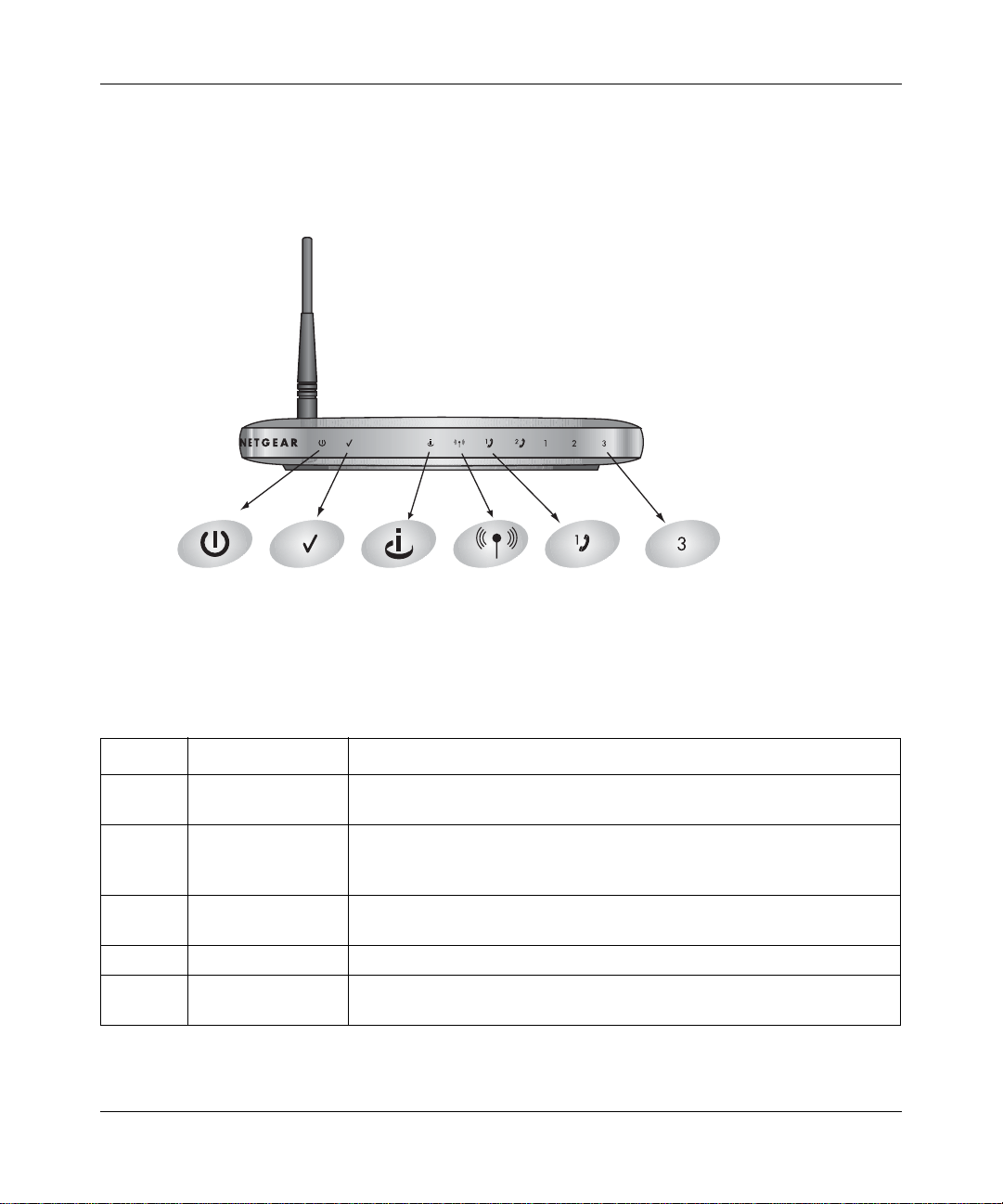
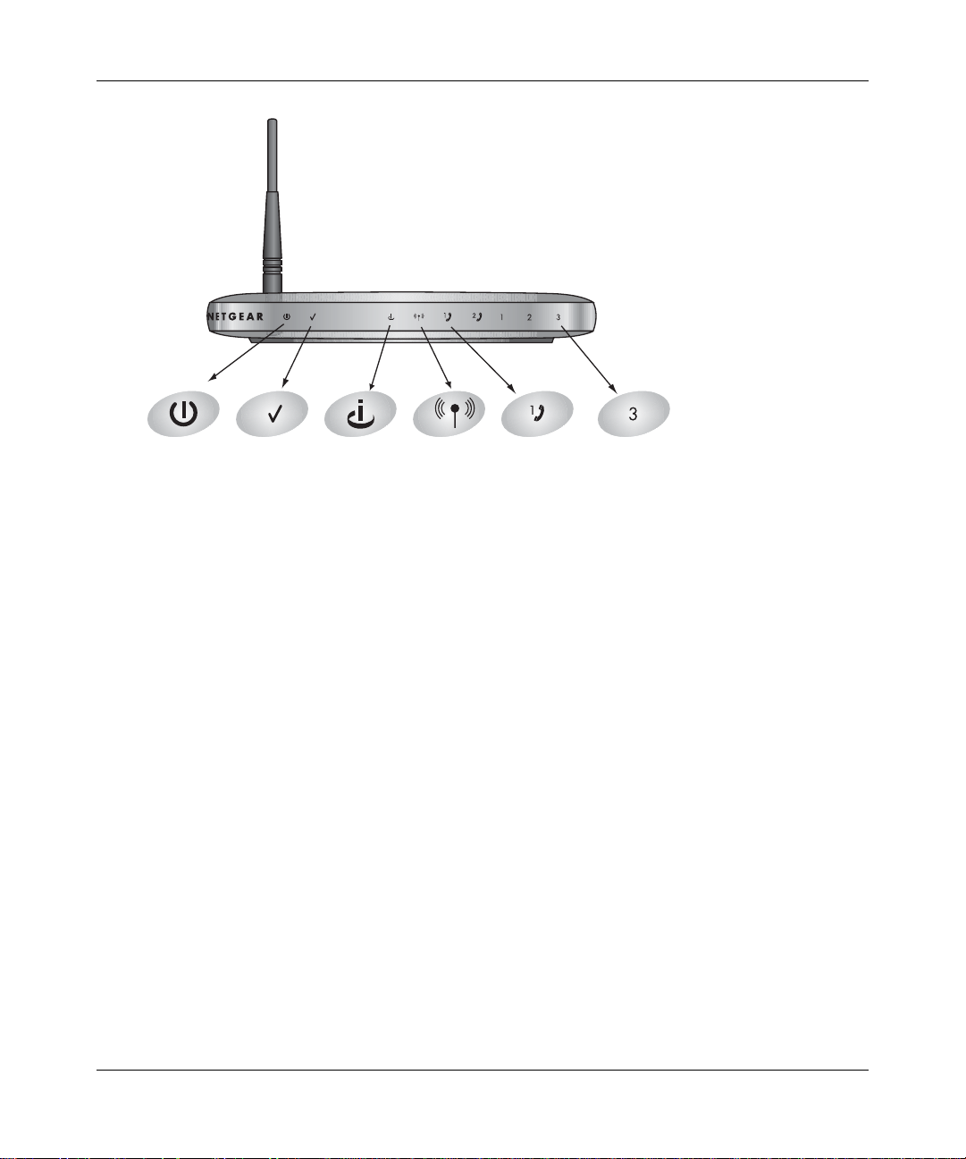
The Front Panel
The front of the WGR826V Wireless Router includes these status lights you can use to verify
connections.
Power Internet Port Wireless LAN Port 3Call Agent Phone 1
Figure 2-1: WGR826V Front Panel
Viewed from left to right, the table below describes the lights on the front panel of the router.
Table 2-1. Status Light Descriptions
Label Activity Description
Power On Green Solid
Off
Call Agent On Green Solid
Blinking
Off
Internet
Port
Wireless On The 802.11g wireless interface is enabled.
Internet
Port
On
Blink
On
Blink
2-2 Getting to Know Your NETGEAR Wireless Router
Power is supplied to the router.
Power is not supplied to the router.
The router is registered with the call agent.
The router is registering with the call agent.
The router is not registered.
The Internet port has detected a link with an attached device.
Data is being transmitted or received by the Internet port.
The Internet port has detected a link with an attached device.
Data is being transmitted or received by the Internet port.
202-10051-01, March 2005
Page 17

Reference Manual for the 54 Mbps Wireless Router with Phone Adapter WGR826V
Table 2-1. Status Light Descriptions (continued)
Label Activity Description
Phone
*
Port
Green Fast Blinking
(60Hz)
Green Slow
Port is enabled and trying to register to the server (1) during boot time or
(2) failed just previously and is attempting to re-register.
Port is ready to use and currently on hook (in talking state).
Blinking (30Hz)
Repeat of "Green
Slow Blinking
Port is ready to use and currently on hook with Message Waiting. If the
phone goes off-hook, then it will be Green Slow Blinking (30Hz).
(30Hz) Twice and
then OFF for 5
seconds"
OFF Port account is disabled/inactive.
Green ON Port is ready to use and currently on hook.
LAN Ports Green
Amber
*
An occasional quick flash of the phone LEDs is normal and indicates that the TA is communicating with the call agent.
The LAN port has detected a 100 Mbps link with an attached device.
The LAN port has detected a 10 Mbps link with an attached device.
Getting to Know Your NETGEAR Wireless Router 2-3
202-10051-01, March 2005
Page 18
Reference Manual for the 54 Mbps Wireless Router with Phone Adapter WGR826V
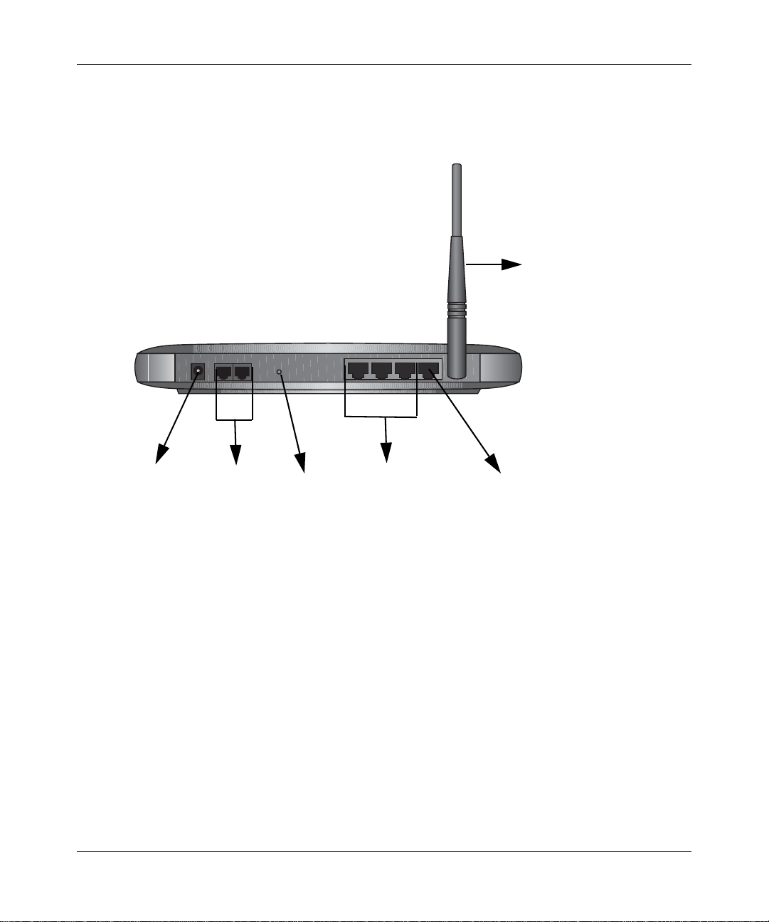
The Rear Panel
The rear panel of the WGR826V router contains the items listed below.
Wireless
Antenna
1
2
Power
Figure 1-2: WGR826V Rear Panel
2 Phone
Ports
32
Reset
Button
3 LAN
Ports
1
Internet Port
Viewed from left to right, the rear panel contains the following features:
• Outlet for 12V DC @ 1.5A output AC power adapter
• Two phone ports
• Factory default reset push button
• Three LAN phone ports
• Internet (WAN) Ethernet port for connecting the router to a cable or DSL modem
• Wireless antenna
2-4 Getting to Know Your NETGEAR Wireless Router
202-10051-01, March 2005
Page 19

Chapter 3
Connecting the Router to the Internet
This chapter describes how to set up the router on your local area network (LAN) and connect to
the Internet. You will find out how to configure your wireless router for Internet access.
Follow these instructions to set up your router.
Prepare to Install Your Wireless Router
• For Cable Modem Service: When you perform the wireless router setup steps be sure to use
the computer you first registered with your cable ISP.
• For DSL Service: You may n eed information such as the DSL login name/e-mail address and
password in order to complete the wireless router setup.
Before proceeding with the wireless router installation, familiarize yourself with the contents of
the Setup CD, especially this manual and the tutorials for configuring computers for networking.
First, Connect the Wireless Router to Your Network
1. CONNECT THE WIRELESS RO UT ER, THE COMPUTER, AND THE MODEM
a. Turn off your computer.
b. Turn off the cable or DSL broadband modem.
Connecting the Router to the Internet 3-1
202-10051-01, March 2005
Page 20
Reference Manual for the 54 Mbps Wireless Router with Phone Adapter WGR826V
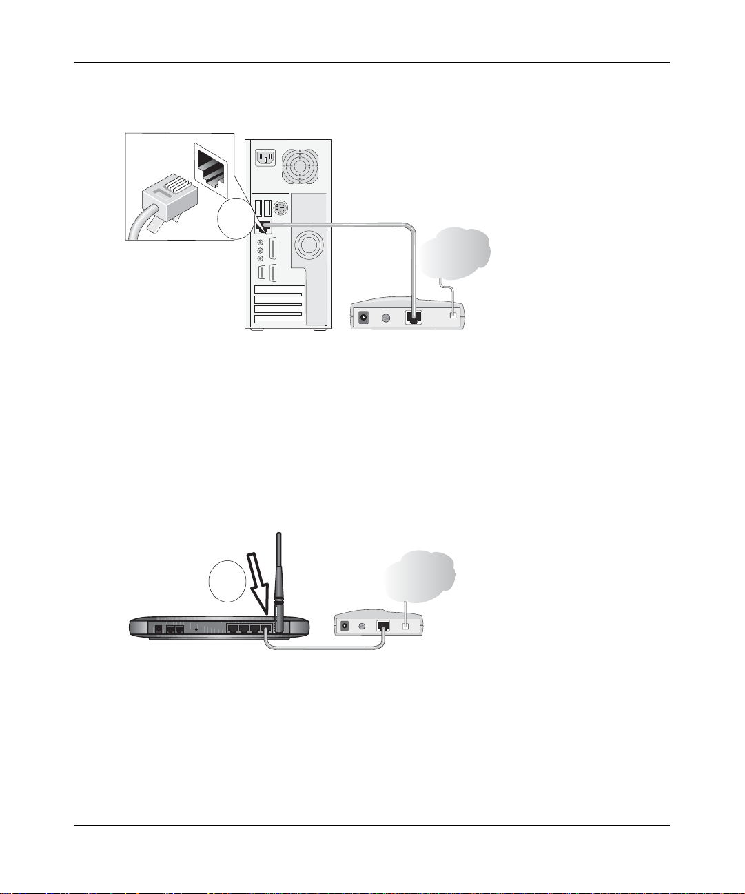
Locate the Ethernet cable (cable 1 in the diagram) that connects your PC to the modem.
c.
A
&DEOH
,QWHUQHW
FRPSXWHU
Figure 3-1: Disconnect the Ethernet cable from the computer
d.
Disconnect the cable at the computer end only, point A in the diagram above.
e. Look at the label on the bottom of the wireless router. Locate the Internet port. Securely
insert the Ethernet cable from your modem (cable 1 in the diagram below) into the Internet
port of the wireless router as shown in point B of the diagram below.
,QWHUQHW3RUW
PRGHP
,QWHUQHW
B
5RXWHU
&DEOH
Figure 3-2: Connect the wireless router to the modem
Note: Place the WGR826V Wireless Router in a location which conforms to the “Observe
Performance, Placement, and Range Guidelines” on page 5-1. The stand provided with the
wireless router provides a convenient, space-saving way of installing the wireless router.
Avoid stacking it on other electronic equipment.
3-2 Connecting the Router to the Internet
202-10051-01, March 2005
0RGHP
Page 21
Reference Manual for the 54 Mbps Wireless Router with Phone Adapter WGR826V
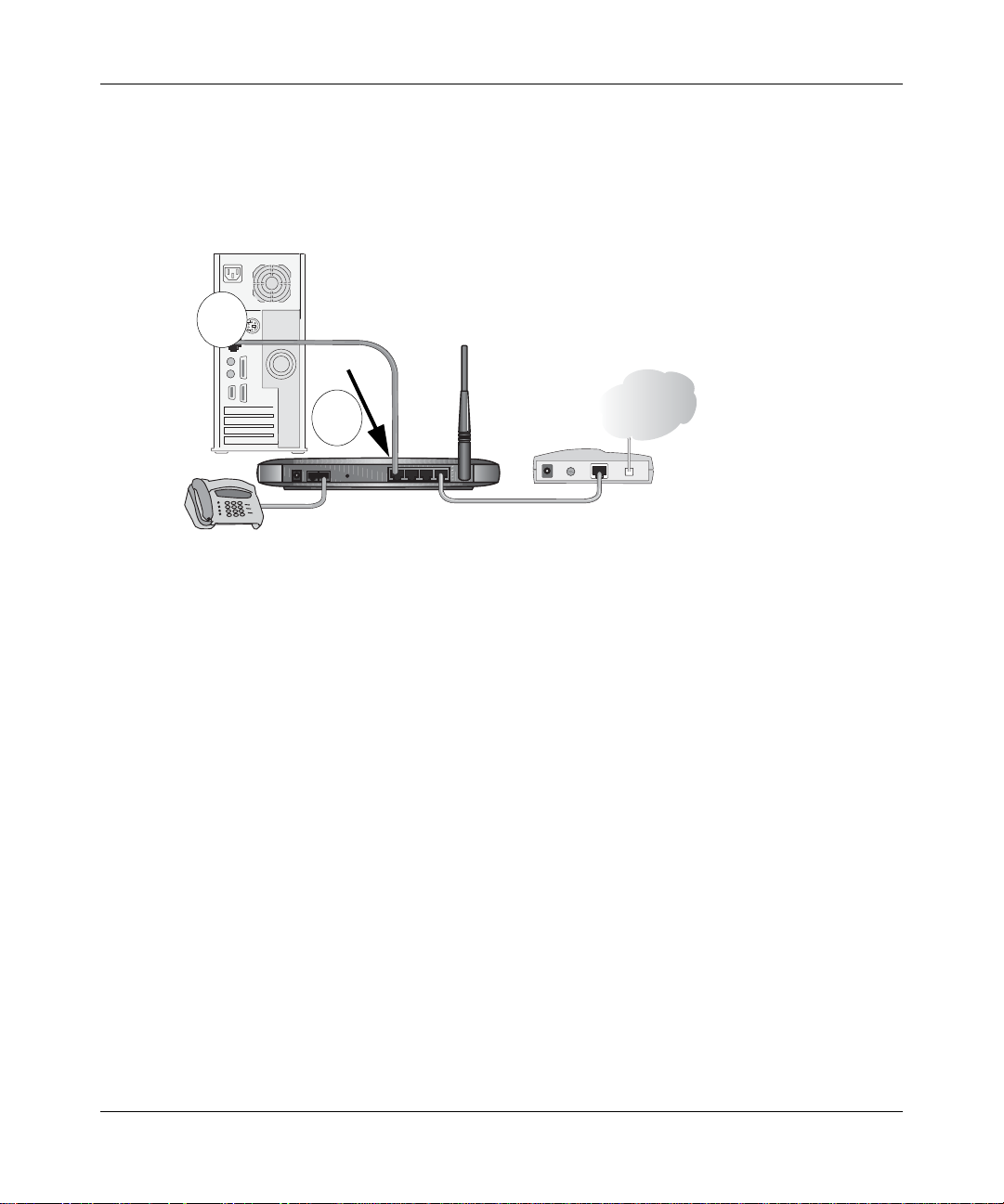
Securely insert the cable that came with your wireless router (the NETGEAR cable in the
f.
diagram below) into a LAN port on the router such as LAN port 4 (point C in the
diagram), and the other end into the Ethernet port of your computer (point D in the
diagram).
&RPSXWHU
1(7*($5
D
&DEOH
C
5RXWHU
,QWHUQHW
0RGHP
+j
Figure 3-3: Connect the computer to the wireless router
3KRQH
3RUWV
/$1
3RUWV
• If you have AT&T CallVantageSM Service or plan to order it, connect a telephone to
Phone Port 1 on the Wireless Router using a standard phone cord (not included).
Your network cables are connected and you are ready to restart your network.
2. RESTART YOUR NETWORK IN THE CORRECT SEQUENCE
Warning: Failure to restart your network in the correct sequence could prevent you from
connecting to the Internet.
a. First, plug in and turn on the broadband modem. Wait about 2 minutes.
b. Now, plug in the power cord to your wireless router. Wait about 2 minutes.
c. Last, turn on your computer.
Note: For DSL customers, if software logs you in to the Internet, do not run that software. Y ou
may need to go to the Internet Explorer T ools menu, Internet Options, Connections tab page
where you can select “Never dial a connection.”
Connecting the Router to the Internet 3-3
202-10051-01, March 2005
Page 22
Reference Manual for the 54 Mbps Wireless Router with Phone Adapter WGR826V
Power Internet Port Wireless LAN Port 3Call Agent Phone 1
Figure 3-4: Verify the connections according to the status lights on the wireless router
d.
Check the wireless router status lights to verify the following:
• Power: The power light should turn solid green. If it does not, see “Troubleshooting
Tips” on page 3-10.
• Call Agent: The LED will be blinking when the unit is registering with the call agent
and will be solid if the unit is registered with the call agent. The LED will of off if the
unit is not registered.
• Internet: The Internet port light should be lit. If not, make sure the Ethernet cable is
securely attached to the wireless router Internet port and the modem, and the modem
is powered on.
• Wireless: The wireless lights should be lit. If not, see “Troubleshooting T ips ” on page
3-10.
• Phone: The Phone light will not be lit until your phone service provider provisions the
phone service. Check the user guide from your phone service provider for details on
provisioning the phone service.
• LAN: A LAN light should be lit. Green indicates your computer is communicating at
100 Mbps; yellow indicates 10 Mbps. If a LAN light is not lit, check that the Ethernet
cable from the computer to the router is securely attached at both ends, and that the
computer is turned on.
3-4 Connecting the Router to the Internet
202-10051-01, March 2005
Page 23
Reference Manual for the 54 Mbps Wireless Router with Phone Adapter WGR826V
3. OPEN A BROWSER AND LOG IN TO THE ROUTER
For DSL customers, if your Internet service provider had you install software logs you in to the
Internet, do not run that software. If such software automatically starts when you open a browser,
you may need to go to the Internet Explorer Tools menu, Internet Options, Connections tab page
where you can select “Never dial a connection.”
1. From the Ethernet connected computer you just set up, open a browser such as Internet
Explorer or Netscape® Navigator.
Note: If your browser connects you to the Internet, you can skip this section and proceed to the
Now, Set Up a Computer for Wireless Connectivity section below.
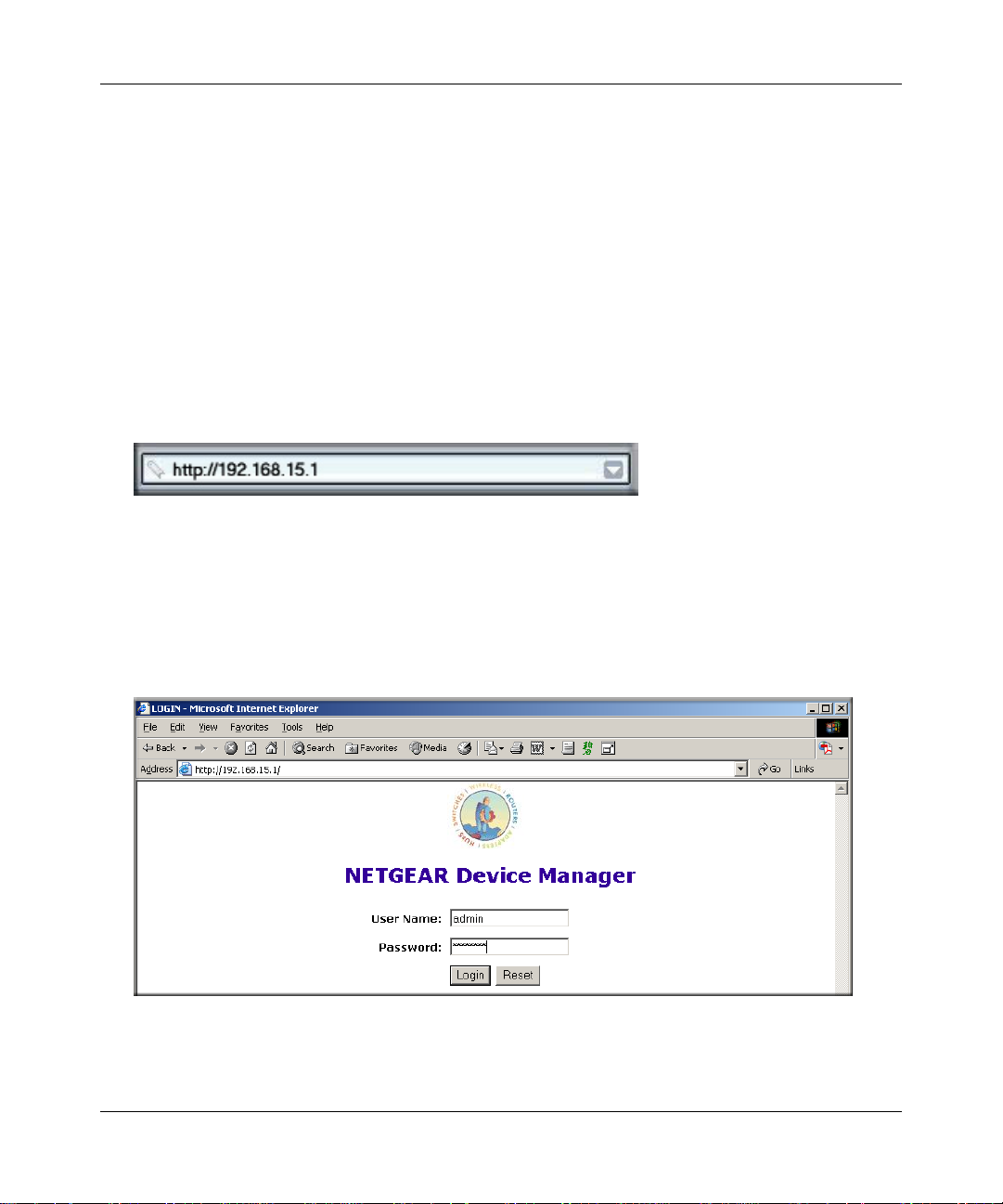
2. Connect to the wireless router by typing http://192.168.15.1 in the address field of your
browser, then click Enter.
3. For security reasons, the router has its own user name and password. When prompted, enter
admin for the router user name and password for the router password, both in lower case
letters.
Note: The router user name and password are not the same as any user name or password you
may use to log in to your Internet connection.
A login window like the one shown below opens:
Figure 3-5: Login window
Connecting the Router to the Internet 3-5
202-10051-01, March 2005
Page 24
Reference Manual for the 54 Mbps Wireless Router with Phone Adapter WGR826V
Note: If you cannot connect to the wireless router, verify your cables are connected correctly,
that the router is powered on, and that the networking setup of your computer is set to obtain
its settings automatically via DHCP. It should be set to obtain both IP and DNS server
addresses automatically, which is usually so. For help with this, please see the tutorials on the
CD.
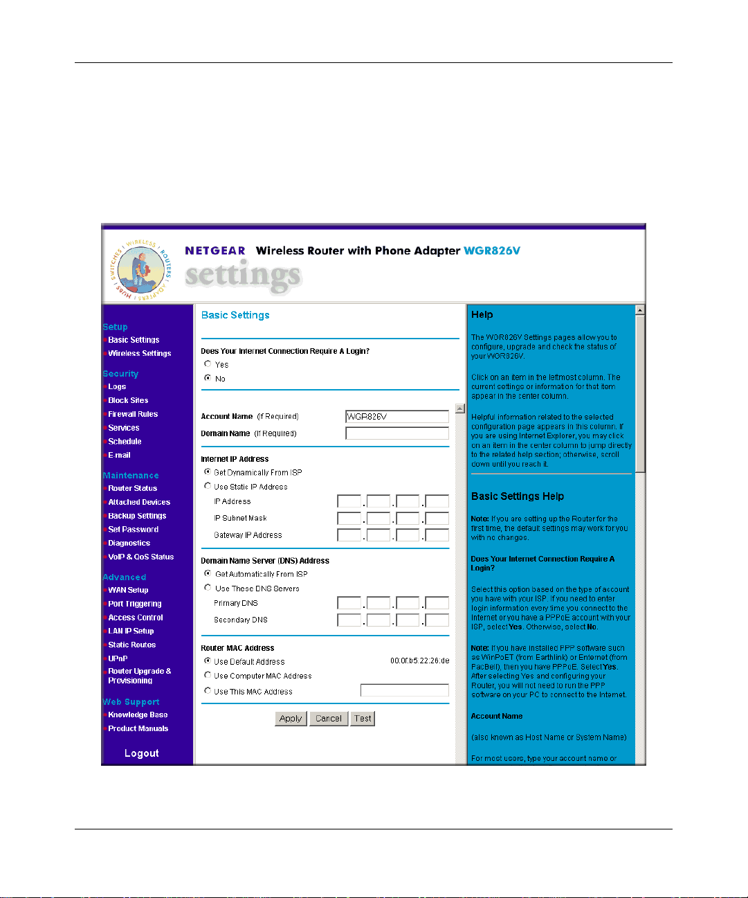
After logging in to the router, you will see the settings main page.
Figure 3-6: Settings main page
3-6 Connecting the Router to the Internet
202-10051-01, March 2005
Page 25
Reference Manual for the 54 Mbps Wireless Router with Phone Adapter WGR826V
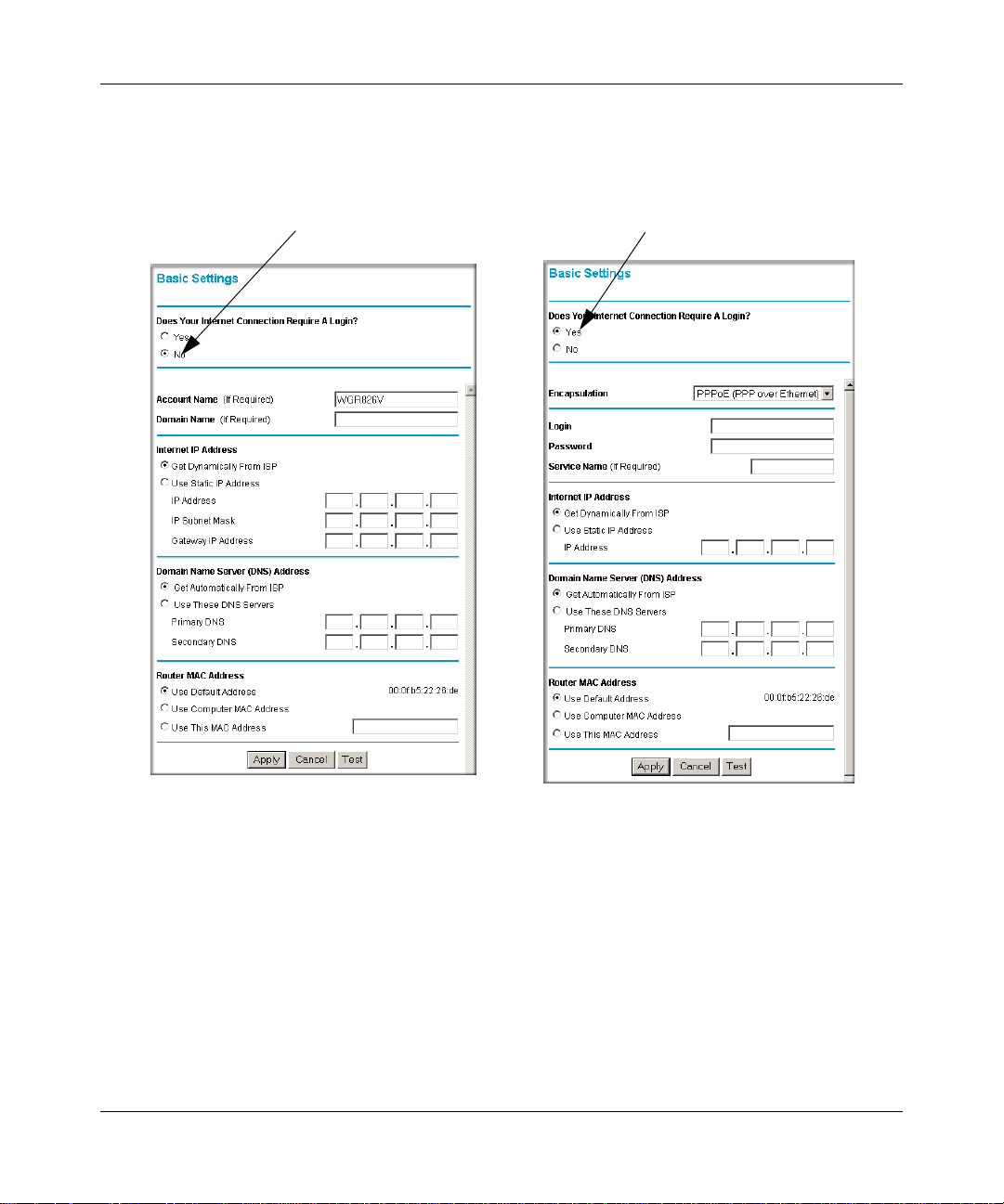
4. CONFIGURE YOUR WIRELESS ROUTER TO CONNECT TO THE INTERNET
Configure the router using the Basic Settings menu shown here:
ISP Does Not Require Login
ISP Does Require Login
Figure 3-7: Browser-based configuration Basic Settings menus
1.
Connect to the wireless router by typing http://192.168.15.1 in the address field of your
browser, then click Enter.
2. For security reasons, the wireless router has its own user name and password. When prompted,
admin for the router user name and password for the router password, both in lower
enter
case letters.
3. Click Basic Settings on the Setup menu.
Connecting the Router to the Internet 3-7
202-10051-01, March 2005
Page 26

Reference Manual for the 54 Mbps Wireless Router with Phone Adapter WGR826V
If your Internet connection does not require a login, click No at the top of the Basic Settings
4.
menu and fill in the settings according to the instructions below. If your Internet connection
does require a login, click Yes, and skip to step 5.
a. Enter your Account Name (may also be called Host Name) and Domain Name.
These parameters may be necessary to access your ISP’s services such as mail or news
servers.
b. Internet IP Address:
If your ISP has assigned you a permanent, fixed (static) IP address for your computer,
select “Use static IP address”. Enter the IP address that your ISP assigned. Also enter the
netmask and the Gateway IP address. The Gateway is the ISP’s router to which your router
will connect.
c. Domain Name Server (DNS) Address:
If you know that your ISP does not automatically transmit DNS addresses to the router
during login, select “Use these DNS servers” and enter the IP address of your ISP’s
Primary DNS Server. If a Secondary DNS Server address is available, enter it also.
Note: If you enter an address here, restart the computers on your network so that these
settings take effect.
d. Router’s MAC Address:
This section determines the Ethernet MAC address that will be used by the router on the
Internet port. Some ISPs will register the Ethernet MAC address of the network interface
card in your computer when your account is first opened. They will then only accept
traffic from the MAC address of that computer. This feature allows your router to
masquerade as that computer by “cloning” its MAC address.
To change the MAC address, select “Use this Computer’s MAC address.” The router
will then capture and use the MAC address of the computer that you are now using. You
must be using the one computer that is allowed by the ISP. Or, select “Use this MAC
address” and type it in here.
e. Click Apply to save your settings.
5. CONFIGURE THE WIRELESS SETTINGS
a. If you are not already logged in to the wireless router, type
192.168.15.1 in your Internet browser address bar and click Enter. When
http://
prompted, type admin for the router user name and password for the password. Click
OK.
3-8 Connecting the Router to the Internet
202-10051-01, March 2005
Page 27
Reference Manual for the 54 Mbps Wireless Router with Phone Adapter WGR826V
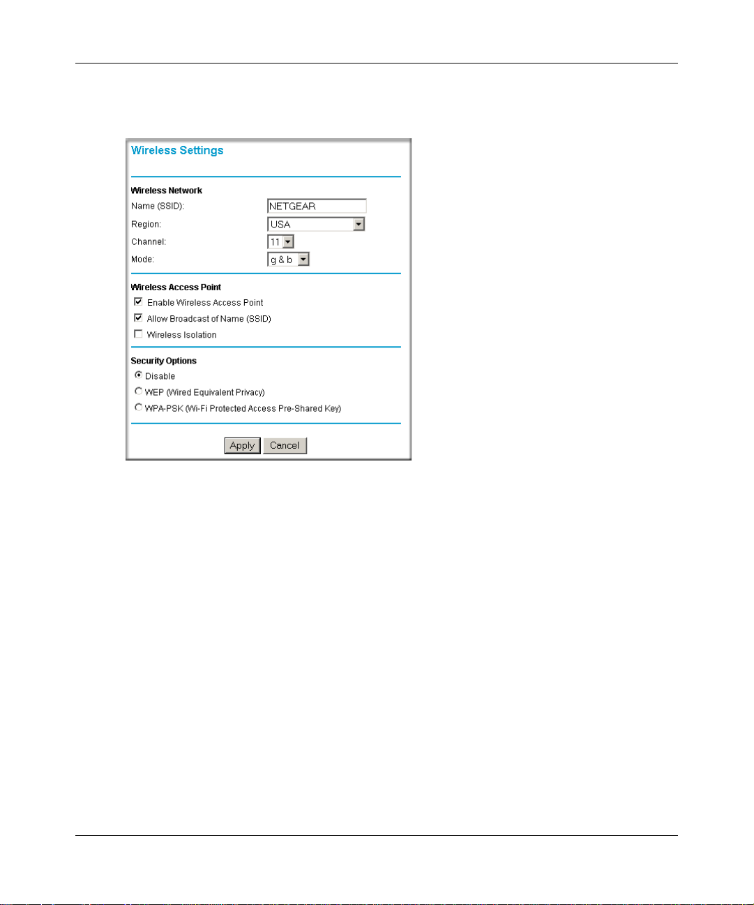
Click Wireless Settings in the main configuration menu. Select a Region. Do not change
b.
the other settings. Click Apply.
Figure 3-8: Wireless Settings menu
c.
Configure your computer to use the Network Name (SSID) NETGEAR with WEP
Security disabled.
Warning: The (SSID) is case sensitive. Entering nETgear will not work.
d. To verify wireless connectivity, connect to the Internet or log in to the WGR826V
Wireless Router from a computer with a wireless adapter.
You are now connected to the Internet and the wireless feature of the wireless router is enabled!
Next, configure your wireless computers to connect to the NETGEAR Network Name (SSID).
Connecting the Router to the Internet 3-9
202-10051-01, March 2005
Page 28
Reference Manual for the 54 Mbps Wireless Router with Phone Adapter WGR826V
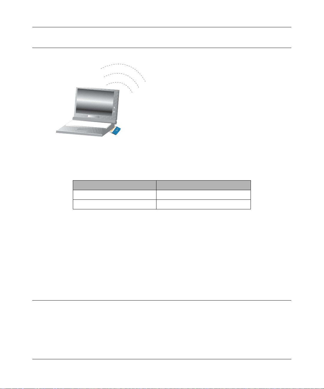
Now, Set Up a Computer for Wireless Connectivity
:LUHOHVV$GDSWHULQD
1RWHERRN&RPSXWHU
Configure the wireless adapter to match your wireless router settings exactly. If you changed the
default Network Name (SSID), be sure to use what you set in the wireless router.
WIRELESS FEATURE DEFAULT SETTING
802.11g Network Name (SSID) NETGEAR
WEP or WPA Security Disabled
Warning: The Network Name (SSID) is case sensitive. Typing nETgear for the SSID will not
work.
If you need to verify the wireless settings of your wireless router, go to a computer that is
connected via an Ethernet cable to the wireless router and simply open a browser. Enter
http://192.168.15.1 in your browser. Then, when prompted, enter admin as the user name and
password for the password both in lower case letters.
You are now wirelessly connected to the Internet with strong security!
Troubleshooting Tips
Here are some tips for correcting simple problems you may have.
Be sure to restart your network in this sequence:
1. Turn off and unplug the modem, turn off the wireless router, and turn off the computer
2. Turn on the modem. Wait about 2 minutes
3-10 Connecting the Router to the Internet
202-10051-01, March 2005
Page 29

Reference Manual for the 54 Mbps Wireless Router with Phone Adapter WGR826V
Turn on the wireless router. Wait about 2 minutes
3.
4. Turn on the computer.
Make sure the Ethernet cables are securely plugged in.
• The Internet status light on the wireless router will be lit if the Ethernet cable to the wireless
router from the modem is plugged in securely and the modem and wireless router are turned
on.
• For each powered on computer connected to the wireless router with a securely plugged in
Ethernet cable, the corresponding wireless router LAN port status light will be lit. The label on
the bottom of the wireless router identifies the number of each LAN port.
Make sure the wireless settings in the computer and router match exactly.
The Wireless Network Name (SSID) and security settings of the router and wireless computer
must match exactly.
Make sure the network settings of the computer are correct.
• LAN and wirelessly connected computers must be configured to obtain an IP address
automatically via DHCP. Please see Appendix C, “Preparing Your Network” or the animated
tutorials on the CD for help with this.
• Some cable modem ISPs require you to use the MAC address of the computer registered on
the account. If so, in the Router MAC Address section of the Basic Settings menu, select “Use
this Computer’s MAC Address.” The router will then capture and use the MAC address of the
computer that you are now using. You must be using the computer that is registered with the
ISP. Click Apply to save your settings. Restart the network in the correct sequence.
Check the router status lights to verify correct router operation.
• If the Power light does not turn solid green within 2 minutes after turning the router on, reset
the router according to the instructions in “Restoring the Default Configuration and Password”
on page 8-7.
• If the Wireless light does not come on, verify that the wireless feature is turned on according to
the instructions in “Understanding Wireless Settings” on page 5-3.
Connecting the Router to the Internet 3-11
202-10051-01, March 2005
Page 30

Reference Manual for the 54 Mbps Wireless Router with Phone Adapter WGR826V
This page intentionally left blank
3-12 Connecting the Router to the Internet
202-10051-01, March 2005
Page 31

Chapter 4
Content Filtering
This chapter describes how to use the content filtering features of the WGR826V 54 Mbps
Wireless Router with Phone Adapter to protect your network. These features can be found by
clicking on the Content Filtering heading in the Main Menu of the browser interface.
Content Filtering Overview
The WGR826V 54 Mbps Wireless Router with Phone Adapter provides you with Web content
filtering options, plus browsing activity reporting and instant alerts via e-mail. Parents and
network administrators can establish restricted access policies based on time of day, Web
addresses and Web address keywords. You can also block Internet access by applications and
services, such as chat or games.
To configure these features of your router, click on the subheadings under the Content Filtering
heading in the Main Menu of the browser interface. The subheadings are described below:
Firewall Rules
The Firewall will always block DoS (Denial of Service) attacks. A DoS attack does not attempt to
steal data or damage your PCs, but overloads your Internet connection so you can not use it - the
service is unavailable. As well, you can use this screen to create Firewall rules to block or allow
specific traffic.
Note: This feature is for Advanced Administrators only! Incorrect configuration will cause serious
problems.
Content Filtering 4-1
202-10051-01, March 2005
Page 32

Reference Manual for the 54 Mbps Wireless Router with Phone Adapter WGR826V
Click on Firewall Rules on the Main menu bar to see the Firewall Rules page:
Figure 4-1: Firewall Rules menu
• Outbound Services: This lists all existing firewall rules for outbound traffic. If you have not
defined any firewall rules, only the default firewall rule will be listed. The default firewall rule
allows all outgoing traffic.
To create a new firewall rule:
a. Click the "Add" button. (It does not matter which radio button is selected)
The "Outbound Service" screen will be displayed. This screen has its own help file.
b. Complete the "Outbound Service" screen, and save the data. The new firewall rule will be
listed in the table when you return to this screen.
4-2 Content Filtering
202-10051-01, March 2005
Page 33

Reference Manual for the 54 Mbps Wireless Router with Phone Adapter WGR826V
To make changes to an existing firewall rule:
a. Click the radio button at the beginning of that row in the table.
b. Click the button for the desired actions:
• Edit - to make any changes to the firewall rule definition. The "Outbound Service"
screen will be displayed, with the data for the selected firewall rule.
• Move - to move the selected firewall rule to a new position in the table. You will be
prompted for the new position.
• Delete - to delete the selected firewall rule.
• Inbound Services: This lists all existing firewall rules for inbound traffic. If you have not
defined any firewall rules, only the default firewall rule will be listed. The default firewall rule
blocks all inbound traffic.
To create a new firewall rule:
a. Click the "Add" button. (It does not matter which radio button is selected)
The "Inbound Service" screen will be displayed. This screen has its own help file.
b. Complete the "Inbound Service" screen, and save the data. The new rule will be listed in
the table when you return to this screen.
To make changes to an existing firewall rule:
a. Click the radio button next to a row in the table.
b. Click the button for the desired actions:
• Edit - to make any changes to the firewall rule definition. The "Inbound Service"
screen will be displayed, with the data for the selected firewall rule.
• Move - to move the selected firewall rule to a new position in the table. You will be
prompted for the new position.
• Delete - to delete the selected firewall rule.
• Ping Response and Telnet
– If you want the router to not respond to a 'ping' from the Internet, deselect the Respond to
Ping on Internet WAN Port check box. This option, however, should be enabled to allow
the AT&T Call Server to adjust for optimum voice quality settings.
– Click on (enable) the checkbox of T elnet will allow you to telnet into the router and see the
system settings from LAN. Be very cautious to enable this functionality.
Content Filtering 4-3
202-10051-01, March 2005
Page 34

Reference Manual for the 54 Mbps Wireless Router with Phone Adapter WGR826V
• Pass Through: This feature enables you to allow certain traffic, such as L2TP, PPTP and IPSec
Protocols. When you enable a type of traffic, the Router allows that traffic to Internet.
• Attacks
– Enabling the Stealth Mode will allow the Router to work in stealth mode. It will not
acknowledge its existence on the network. If it is disabled (unchecked), Router will work
in normal mode.In stealth mode the router silently discards the incoming packets that do
not have access policies.
– Check on (enable) the SYN Flood Check will enable the Router to perform SYN Flood
attack check on the traffic. Unchecking the checkbox will disable the Router to conduct
the SYN Flood check.
Outbound Services
You can use this screen to define a new Outbound Firewall rule, or edit an existing rule. Outbound
Firewall rules are used to block or allow access by computers on your network to services or
applications on the Internet.
Click on Add Outbound Services on the Firewall Rules menu to see the Outbound Services page:
Figure 4-2: Outbound Services menu
4-4 Content Filtering
202-10051-01, March 2005
Page 35

Reference Manual for the 54 Mbps Wireless Router with Phone Adapter WGR826V
• Services: Select the desired Service or application to be covered by this firewall rule. If the
desired service or application does not appear in the list, you must define it using the Services
menu.
• Action: Select the desired action for packets covered by this rule:
–BLOCK always
– ALLOW always
– ALLOW by schedule, otherwise Block
Note:
Any outbound traffic which is not blocked by firewall rules you create will be allowed by the
Default rule.
ALLOW rules are only useful if the traffic is already covered by a BLOCK rule. (That is, you
wish to allow a subset of traffic which is currently blocked by another rule.)
To define the Schedule used in these selections, use the "Schedule" screen.
• LAN users: These settings determine which computers on your network are affected by this
firewall rule, based on their source (LAN) IP address. Select the desired option:
– Any - All local IP addresses are covered by this firewall rule.
– Address range - If this option is selected, you must enter the "Start" and "Finish" fields.
– Single address - Enter the required address in the "Start" fields.
• WAN Servers: These settings determine which Internet locations are covered by the firewall
rule, based on their d estimation (WAN) IP address. Select the desired option:
– Any - All Internet IP address are covered by this firewall rule.
– Address range - If this option is selected, you must enter the "Start" and "Finish" fields.
– Single address - Enter the required address in the "Start" fields.
• Log: This determines whether packets covered by this firewall rule are logged. Select the
desired action:
– Never - never log traffic considered by this firewall rule, whether it matches or not.
– Match - Log traffic only it matches this firewall rule. (The action is determined by this
firewall rule.)
Content Filtering 4-5
202-10051-01, March 2005
Page 36

Reference Manual for the 54 Mbps Wireless Router with Phone Adapter WGR826V
Inbound Services
You can use this screen to define a new Inbound firewall rule, or edit an existing firewall rule.
Firewall rules can be used to block or allow specific traffic. This feature is for Advanced
Administrators only! Incorrect configuration will cause serious problems.
Click on Add Inbound Services on the Firewall Rules menu to see the Inbound Services page:
Figure 4-3: Inbound Services menu
• Services: Select the desired Service. This determines which packets are covered by this
firewall rule. If necessary, you can define a new Service on the "Services" screen, by defining
the protocols and port numbers used by the Service.
If you want to create a new custom service with incoming protocol and port (or range of ports)
here itself then select "Create custom service". Select TCP or UDP or TCP/UDP and then
enter incoming port or Range of Ports.
Start port should be between 1 to 65535 and Finish port should be entered only if you want to
allow range of ports. Ensure that Finish port is always greater than or equal to start port.
• Action: Select the desired action for packets covered by this firewall rule:
– ALLOW always
– ALLOW by schedule, otherwise Block
–BLOCK always
4-6 Content Filtering
202-10051-01, March 2005
Page 37

Reference Manual for the 54 Mbps Wireless Router with Phone Adapter WGR826V
Note:
Any inbound traffic which is not allowed by firewall rules you create will be blocked by the
Default rule.
BLOCK rules are only useful if the traffic is already covered by an ALLOW rule. (That is, you
wish to block a sub-set of traffic which is currently allowed by another rule.)
To define the Schedule used in these selections, use the "Schedule" screen.
• LAN Server: Enter the IP address of the PC or Server on your LAN which will receive the
inbound traffic covered by this rule.This field is disabled if action selected is "Block Always".
• Forwarding Port
– If you select 'Same as Incoming port' then all incoming traffic on specified Service is
forwarded to LAN server without modifying Destination Port.
– If you select 'Forward to another port range' then all incoming traffic received on the
Service port (or range of ports) is forwarded to this port or range of ports of the LAN
Server.
– This field is disabled if action selected is "Block Always".
– If you want to forward the traffic to a single port then enter port value in start port and
leave finish port empty.
– If you want to forward the traffic to range of ports then enter non zero value in finish port
and make sure that service record attached to this rule has range of ports and range is equal
to that of forwarding ports.
– For example if you select Service as HTTP (TCP/80), LAN Server IP address as
192.168.15.10 and Forwarding port as 8080 then all traffic coming from internet on
– TCP/80 (HTTP) to this Router is redirected to TCP/8080 port of 192.168.15.10
• WAN Users: These settings determine which packets are covered by the firewall rule, based on
their source (WAN) IP address. Select the desired option:
– Any All IP addresses are covered by this firewall rule.
– Address range If this option is selected, you must enter the "Start" and "Finish" fields.
– Single address Enter the required address in the "Start" fields.
• Log: This determines whether packets covered by this firewall rule are logged. Select the
desired action.
– Never - never log traffic considered by this firewall rule, whether it matches or not.
– Match - Log traffic only it matches this firewall rule. (The action is determined by this
firewall rule.)
Content Filtering 4-7
202-10051-01, March 2005
Page 38

Reference Manual for the 54 Mbps Wireless Router with Phone Adapter WGR826V
Blocking Access to Internet Sites
The WGR826V Wireless Router allows you to restrict access based on Web addresses and Web
address keywords. Up to 255 entries are supported in the Keyword list. The Block Sites menu is
shown in Figure 4-4 below:
Figure 4-4: Block Sites menu
To add a keyword or domain, type it in the Keyword box, click Add Keyword, then click Apply.
To delete a keyword or domain, select it from the list, click Delete Keyword, then click Apply.
Keyword application examples:
• If the keyword “XXX” is specified, the URL <http://www .badstuff.com/xxx.html> is blocked.
• If the keyword “.com” is specified, only Web sites with other domain suffixes (such as .edu or
.gov) can be viewed.
• If you wish to block all Internet browsing access during a scheduled period , enter the keyword
“.” and set the schedule in the Schedule menu.
Click Apply.
4-8 Content Filtering
202-10051-01, March 2005
Page 39

Reference Manual for the 54 Mbps Wireless Router with Phone Adapter WGR826V
Blocking Access to Internet Services
The WGR826V Wireless Router allows you to block the use of certain Internet services by PCs on
your network. This is called services blocking or port filtering. The Block Services menu is shown
below:
Figure 4-5: Block Services menu
Services are functions performed by server computers at the request of client computers. For
example, Web servers serve Web page s, time servers serve time and date information, and game
hosts serve data about other players’ moves. When a computer on your network sends a request for
service to a server computer on the Internet, the requested service is identified by a service or port
number. This number appears as the destination port number in the transmitted IP packets. For
example, a packet that is sent with destination port number 80 is an HTTP (Web server) request.
To enable service blocking, select either Per Schedule or Always, then click Apply. If you want to
block by schedule, be sure that a time period is specified in the Schedule menu.
Content Filtering 4-9
202-10051-01, March 2005
Page 40

Reference Manual for the 54 Mbps Wireless Router with Phone Adapter WGR826V
T o specify a service for blocking, click Add. The Add Services menu will appear, as shown below:
Figure 4-6: Add Services menu
From the Service Type list, select the application or service to be allowed or blocked. The list
already displays several common services, but you are not limited to these choices. To add any
additional services or applications that do not already appear, select User Defined.
Configuring a User Defined Service
To define a service, first you must determine which port number or range of numbers is used by
the application. The service numbers for many common protocols are defined by the Internet
Engineering Task Force (IETF) and published in RFC1700, “Assigned Numbers.” Service
numbers for other applications are typically chosen from the range 1024 to 65535 by the authors of
the application. This information can usually be determined by contacting the publisher of the
application or from user groups of newsgroups.
Enter the Starting Port and Ending Port numbers. If the applicatio n uses a single port number , enter
that number in both boxes.
If you know that the application uses either TCP or UDP , select the appropriate protocol. If you are
not sure, select Both.
4-10 Content Filtering
202-10051-01, March 2005
Page 41

Reference Manual for the 54 Mbps Wireless Router with Phone Adapter WGR826V
Scheduling When Blocking Will Be Enforced
The WGR826V Wireless Router allows you to specify when blocking will be enforced. The
Schedule menu is shown below:
Figure 4-7: Schedule menu
• Use this schedule for blocking content. Check this box if you wish to enable a schedule for
Content Filtering. Click Apply .
• Days to Block. Select days to block by checking the appropriate boxes. Select Everyday to
check the boxes for all days. Click Apply.
• Time of Day to Block. Select a start and end time in 23:59 format. Select All day for 24 hour
blocking. Click Apply.
Be sure to select your Time Zone in the E-Mail menu.
Content Filtering 4-11
202-10051-01, March 2005
Page 42

Reference Manual for the 54 Mbps Wireless Router with Phone Adapter WGR826V
Viewing Logs of Web Access or Attempted Web Access
The log is a detailed record of what W eb sites you have accessed or attempted to access. Up to 128
entries are stored in the log. Log entries will only appear when keyword blocking is enabled. An
example is shown below:
Figure 4-8: Logs menu
4-12 Content Filtering
202-10051-01, March 2005
Page 43

Reference Manual for the 54 Mbps Wireless Router with Phone Adapter WGR826V
Log entries are described in Table 4-1
Table 4-1. Log entry descriptions
Field Description
Number The index number of the content filter log entries. 128 entries
are available numbered from 0 to 127. The log will keep the
record of the latest 128 entries.
Date and Time The date and time the log entry was recorded.
Source IP The IP address of the initiating device for this log entry.
Action This field displays whether the access was blocked or allowed.
The name or IP address of the Web site or newsgroup visited or
attempted to access.
Log action buttons are described in Table 4-2
Table 4-2. Log action buttons
Field Description
Refresh Click this button to refresh the log screen.
Clear Log Click this button to clear the log entries.
Send Log Click this button to E-mail the log immediately.
Content Filtering 4-13
202-10051-01, March 2005
Page 44

Reference Manual for the 54 Mbps Wireless Router with Phone Adapter WGR826V
Configuring E-Mail Alert and Web Access Log Notifications
In order to receive logs and alerts by E-mail, you must provide your E-mail information in the
E-Mail menu, shown below:
Figure 4-9: Email menu
• Turn e-mail notification on
Check this box if you wish to receive e-mail logs and alerts from the router.
• Your outgoing mail server
Enter the name of your ISP’s outgoing (SMTP) mail server (such as mail.myISP.com). You
may be able to find this information in the configuration menu of your e-mail program. If you
leave this box blank, log and alert messages will not be sent via e-mail.
• Send to this e-mail address
Enter the e-mail address to which logs and alerts are sent. This e-mail address will also be used
as the From address. If you leave this box blank, log and alert messages will not be sent via
e-mail.
You can specify that logs are automatically sent to the specified e-mail address with these options:
• Send alert immediately
Check this box if you would like immediate notification of attempted access to a blocked site.
• Send logs according to this schedule
Specifies how often to send the logs: Hourly, Daily, Weekly, or When Full.
4-14 Content Filtering
202-10051-01, March 2005
Page 45

Reference Manual for the 54 Mbps Wireless Router with Phone Adapter WGR826V
– Day for sending log
Specifies which day of the week to send the log. Relevant when the log is sent weekly or
daily.
– Time for sending log
Specifies the time of day to send the log. Relevant when the log is sent daily or weekly.
If the Weekly, Daily or Hourly option is selected and the log fills up before the specified
period, the log is automatically e-mailed to the specified e-mail address. After the log is sent,
the log is cleared from the router’s memory. If the router cannot e-mail the log file, the log
buffer may fill up. In this case, the router overwrites the log and discards its contents.
The WGR826V Wireless Router uses the Network Time Protocol (NTP) to obtain the current time
and date from one of several Network Time Servers on the Internet. In order to localize the time
for your log entries, you must specify your Time Zone:
•Time Zone
Select your local time zone. This setting will be used for the blocking schedule and for
time-stamping log entries.
• Daylight Savings Time
Check this box if your time zone is currently under daylight savings time.
Content Filtering 4-15
202-10051-01, March 2005
Page 46

Reference Manual for the 54 Mbps Wireless Router with Phone Adapter WGR826V
4-16 Content Filtering
202-10051-01, March 2005
Page 47

Chapter 5
Optimizing Wireless Connectivity and Security
This chapter describes how to configure the wireless features of your WGR826V Wireless Router.
In planning your wireless network, you should consider the level of security required. You should
also select the physical placement of your firewall in order to maximize the network speed.
The full manual with detailed how to instructions is available via the Documentation link in the
configuration utility of the WGR826V Wireless Router.
Observe Performance, Placement, and Range Guidelines
The operating distance or range of your wireless connection can vary significantly bas ed on the
physical placement of the Wireless Access Point. The latency, data throughput performance, and
notebook power consumption of wireless adapters also vary depending on your configuration
choices.
Note: Failure to follow these guidelines can result in significant performance
degradation or inability to wirelessly connect to the router. For complete range/
performance specifications, please see Appendix A, “Technical Specifications.”
For best results, place your Wireless Access Point:
• Near the center of the area in which your computers will operate.
• In an elevated location such as a high shelf where the wirelessly connected computers have
line-of-sight access (even if through walls).
• Away from sources of inte rference, such as computers, microwaves, and 2.4 GHz cordless
phones.
• Away from large metal surfaces.
• Put the antenna in a vertical position for best side-to-side coverage. Put the antenna in a
horizontal position for best up-and-down coverage.
The time it takes to establish a wireless connection can vary depending on both your security
settings and placement. WEP or WPA connections can take slightly longer to establish.
Optimizing Wireless Connectivity and Security 5-1
202-10051-01, March 2005
Page 48

Reference Manual for the 54 Mbps Wireless Router with Phone Adapter WGR826V
:LUHOHVV'DWD
6HFXULW\2SWLRQV
5DQJHXSWRIRRWUDGLXV
2SHQV\VWHPHDV\EXWQRVHFXULW\
0$&DFFHVVOLVWQRGDWDVHFXULW\
:(3VHFXULW\EXWVRPHSHUIRUPDQFHLPSDFW
:3$36.YHU\VWURQJVHFXULW\
Implement Appropriate Wireless Security
Note: Indoors, computers can connect over 802.11b/g wireless networks at ranges of up
to 300 feet. Such distances can allow for others outside of your immediate area to access
your network.
Unlike wired network data, your wireless data transmissions can be received well beyond your
walls by anyone with a compatible adapter. For this reason, use the security features of your
wireless equipment. The WGR826V Wireless Router provides highly effective security features
which are covered in detail in this chapter. Deploy the security features appropriate to your needs.
Figure 5-1: WGR826V wireless data security options
There are several ways you can enhance the security of your wireless network.
• Turn Off the Broadcast of the Wireless Network Name SSID. If you disable broadcast of
the SSID, only devices that have the correct SSID can connect. This nullifies the wireless
network ‘discovery’ feature of some products such as Windows XP, but the data is still fully
exposed to a determined snoop using specialized test equipment like wireless sniffers.
• WEP. Wired Equivalent Privacy (WEP) data encryption provides data security. WEP Shared
Key authentication and WEP data encryption will block all but the most determined
eavesdropper.
• WPA-PSK. Wi-Fi Protected Access (WPA) data encryption provides strong data security.
WPA-PSK will block eavesdropping. Because this is a new standard, wireless device driver
and software availability may be limited.
5-2 Optimizing Wireless Connectivity and Security
202-10051-01, March 2005
Page 49

Reference Manual for the 54 Mbps Wireless Router with Phone Adapter WGR826V
• Turn Off the Wired LAN. If you disable the wireless LAN, wireless devices cannot
communicate with the router at all. You might choose to turn off the wireless the LAN when
you are away and the others in the household all use wired connections.
Understanding Wireless Settings
To configure the Wireless settings of your firewall, click the Wireless Settings link in the main
menu of the browser interface.
Figure 5-2: Wireless Settings menu
• Name (SSID). The SSID is also known as the wireless network name. Enter a value of up to
32 alphanumeric characters. In a setting where there is more than one wireless network,
different wireless network names provide a means for separating the traffic. Any device you
want to participate in a particular wireless network will need to use this SSID for that network.
• Region. This field identifies the region where the WGR826V can be used (when this option is
available). It may not be legal to operate the wireless features of the wireless router in a region
other than one of those identified in this field.
Optimizing Wireless Connectivity and Security 5-3
202-10051-01, March 2005
Page 50

Reference Manual for the 54 Mbps Wireless Router with Phone Adapter WGR826V
• Channel. This field determines which operating frequency will be used. It should not be
necessary to change the wireless channel unless you notice interference problems with another
nearby access point.
• Mode. This field determines which data communications protocol will be used.
• Security Options. These options are the wireless security features you can enable. The table
below identifies the various basic wireless security options.
Table 5-1. Basic Wireless Security Options
Field Description
Disable No wireless security.
WEP WEP offers the following options:
Open System
With Open Network Authentication and 64- or 128-bit WEP Data Encryption, the WGR826V
does perform 64- or 128-bit data encryption but does not perform any authentication.
Shared Key
Shared Key authentication encrypts the SSID and data.
Choose the Encryption Strength (64- or 128-bit data encryption). Manually enter the key
values or enter a word or group of printable characters in the Passphrase box. Manually
entered keys are case sensitive but passphrase characters are not case sensitive.
Note: Not all wireless adapter configuration utilities support passphrase key generation.
Auto
WPA-PSK WPA-Pre-shared Key does perform authentication, uses 128-bit data encryption and
dynamically changes the encryption keys making it nearly impossible to circumvent.
Enter a word or group of printable characters in the Password Phrase box. These characters
are case sensitive.
Note: Not all wireless adapter configuration utilities support WPA. Furthermore, client software
is required on the client. Windows XP and Windows 2000 with Service Pack 3 do include the
client software that supports WPA. Nevertheless, the wireless adapter hardware and driver
must also support WPA.
• Allow Broadcast of Name (SSID). If you disable broadcast of the SSID, only devices that
have the correct SSID can connect. Disabling SSID broadcast nullifies the wireless network
‘discovery’ feature of some products such as Windows XP.
• Enable Wireless Access Point. If you disable the wireless access point, wireless devices
cannot connect to the WGR826V.
5-4 Optimizing Wireless Connectivity and Security
202-10051-01, March 2005
Page 51

Reference Manual for the 54 Mbps Wireless Router with Phone Adapter WGR826V
Default Factory Settings
When you first receive your WGR826V, the default factory settings are shown below. You can
restore these defaults with the Factory Default Restore button on the rear panel. After you install
the WGR826V Wireless Router, use the procedures below to customize any of the settings to
better meet your networking needs.
WIRELESS FEATURE DEFAULT SETTING
Wireless Access Point Enabled
SSID broadcast Enabled
Network Name (SSID) NETGEAR
WPA and WEP Security Disabled
Warning: The Network Name (SSID) and passphrase are case sensitive. Typing nETgear for the
SSID will not work.
Optimizing Wireless Connectivity and Security 5-5
202-10051-01, March 2005
Page 52

Reference Manual for the 54 Mbps Wireless Router with Phone Adapter WGR826V
Information to Gather Before Changing Basic Wireless Settings
Before customizing your wireless settings, print this form and record the following information.
• 802.11g Wireless Network Name (SSID): ______________________________
The SSID, identifies the wireless network. Y ou can use up to 32 alphanumeric characters. The
SSID is case sensitive. The SSID in the wireless adapter card must match the SSID of the
wireless router. In some configuration utilities (such as in Windows XP), the term “wireless
network name” is used instead of SSID.
• If WEP Authentication is Used. Circle one: Open System, Shared Key, or Auto.
Note: If you select Shared Key, the other devices in the network will not connect unless they
are set to Shared Key as well and are configured with the correct key.
– WEP Encryption key size. Choose one: 64-bit or 128-bit. Again, the encryption key size
must be the same for the wireless adapters and the wireless router.
– Data Encryption (WEP) Keys. There are two methods for creating WEP data encryption
keys. Whichever method you use, record the key values in the spaces below.
• Passphrase method. ___________________________ __ _
These characters are case
sensitive. Enter a word or group of printable characters and click the Generate Keys
button. Not all wireless devices support the passphrase method.
• Manual method. These values are not case sensitive. For 64-bit WEP, enter 10 hex
digits (any combination of 0-9 or a-f). For 128-bit WEP, enter 26 hex digits.
Key 1: ___________________________________
Key 2: ___________________________________
Key 3: ___________________________________
Key 4: ___________________________________
• If WPA-PSK Authentication is Used.
– Passphrase: ___________________________ ___
These characters are case sensitive.
Enter a word or group of printable characters. When you use WPA-PSK, the other devices
in the network will not connect unless they are set to WP A-PSK as well and are configured
with the correct Passphrase.
Use the procedures described in the reference manual to configure the WGR826V.
5-6 Optimizing Wireless Connectivity and Security
202-10051-01, March 2005
Page 53

Chapter 6
Doing Basic Router Housekeeping
This chapter describes how to use some of the maintenance features of your WGR826V 54 Mbps
Wireless Router with Phone Adapter. These features can be found by clicking on the Maintenance
heading in the Main Menu of the browser interface. Other maintenance features not presented in
this chapter can be found accessed via links in the browser interface of the wireless router to the
documentation and in the help screens.
Changing the Administrator Password
The default password for the wireless router’s Web Configuration Manager is password. Change
this password to a more secure password.
From the Main Menu of the browser interface, under the Maintenance heading, select Set
Password to bring up the menu shown below.
Figure 6-1: Set Password menu
To change the password, first enter the old password, then enter the new password twice. Click
Apply.
Doing Basic Router Housekeeping 6-1
202-10051-01, March 2005
Page 54

Reference Manual for the 54 Mbps Wireless Router with Phone Adapter WGR826V
Reviewing the Router Status
You can use the Router Status page to check the current settings for your Router. If something
needs to be changed, you will have to change it on the relevant page.
Click on Router Status on the Main menu bar to see the Router Status page:
Figure 6-2: Router Status page
• Account Name: This is the Account Name that you entered in Basic Settings.
6-2 Doing Basic Router Housekeeping
202-10051-01, March 2005
Page 55

Reference Manual for the 54 Mbps Wireless Router with Phone Adapter WGR826V
• Firmware Version: This is the current software the Router is using. This will change if you
upgrade your Router.
• WAN Port: These are the current settings that you set in the Basic Settings page.
– MAC Address - the physical address of the WGR826V, as seen from the Internet.
– IP Address - current Internet IP address. If assigned dynamically, and no Internet
connection exists, this will be blank or 0.0.0.0
– Network Type - indicates either DHCP (IP address is obtained dynamically), PPPoE (IP
address requires a login), or Static (IP is statically entered).
– IP Subnet Mask - the subnet mask associated with the Internet IP address.
– Gateway IP Address - the Gateway associated with the Internet IP address.
– Domain Name Server - displays the address of the current DNS.
• LAN Port: These are the current settings, as set in the LAN IP Setup page.
– MAC Address - the physical address of the WGR826V, as seen from the local LAN.
– IP Address - LAN IP address of the Router.
– DHCP - indicates if the WGR826V is acting as a DHCP Server for devices on your LAN.
– IP Subnet Mask - subnet mask associated with the LAN IP address.
• Wireless Port: These are the current settings, as set in the Wireless Settings page.
– Name (SSID) - Service Set Identifier (SSID) of the WGR826V.
– Region - the location (country).
– Channel/Frequency - the current channel in use and Frequency of the Channel in
GigaHertz.
– Mode - Mode of operation of the Wireless router.
– Wireless AP - indicates if the Access Point feature of the WGR826V is enabled or not. If
not enabled, wireless users will not be connected to the Internet.
– Broadcast Name - indicates if the WGR826V is broadcasting its SSID.
– WEP/WPA Status - indicates whether security is enabled or disabled on the wireless port
and displays the security mode if enabled
– BSSID - Basic service Set Identification. Usually MAC address of the wireless port of the
WGR826V
• Click Connection Status to see information about your current connection.
Doing Basic Router Housekeeping 6-3
202-10051-01, March 2005
Page 56

Reference Manual for the 54 Mbps Wireless Router with Phone Adapter WGR826V
Reviewing the Attached Devices
Click on Attached Devices on the Main menu bar to see the Attached Devices page:
Figure 6-3: Attached Devices page
This page shows the attached devices information. It lists out the device IP Address, Device Name,
MAC (Media Access Control) Address, Lease Start Time and Lease End Time for each computer
attached to the Router.
You cannot chang e any of the values on this page. To update this page and to show the current
attached devices, click on the Refresh button.
6-4 Doing Basic Router Housekeeping
202-10051-01, March 2005
Page 57

Reference Manual for the 54 Mbps Wireless Router with Phone Adapter WGR826V
Backing up Your Settings
Click on Backup Settings on the Main menu bar to see the Backup Settings page:
Figure 6-4: Backup Settings page
This page allows you to backup, restore and erase the Router's current settings.
Once you have the Router working properly, you should backup the information to have it
available if something goes wrong. When you backup the settings, they are saved as a file on your
computer. You can restore the Router's settings from this file.
To create a backup file of the current settings:
1. Click Backup.
2. If you don't have your browser set up to save downloaded files automatically , locate where you
want to save the file, rename it if you like, and click Save.
If you have your browser set up to save downloaded files automatically, the file is saved to the
your browser's download location on the hard disk and is called netgear.cfg.
IMPORTANT! Once you start restoring settings or erasing the Router, do NOT try to go online,
turn off the Router, shutdown the computer or do anything else to the Router until it finishes
restarting! This should only take a minute or so. When the Test light (looks like a check mark)
stops blinking, wait a few more seconds before doing anything with the Router.
Doing Basic Router Housekeeping 6-5
202-10051-01, March 2005
Page 58

Reference Manual for the 54 Mbps Wireless Router with Phone Adapter WGR826V
To restore settings from a backup file:
1. Click Browse.
2. Locate and select the previously saved backup file (by default, netgear.cfg).
3. Click Restore.
A window appears letting you know that the Router has been successfully restored to previous
settings. The Router will restart. This will take about one minute.
IMPORTANT! Do not try to go online, turn off the Router, shutdown the computer or do
anything else to the Router until it finishes restarting! When the Test light (looks like a check
mark) stops blinking, wait a few more seconds before doing anything with the Router.
4. Close the message window.
To erase the current settings and reset the Router to the original factory default settings:
1. Click Erase.
IMPORTANT! Do not try to go online, turn off the Router, shutdown the computer or do
anything else to the Router until the Router finishes restarting! When the Test light (looks like
a check mark) stops blinking, wait a few more seconds before doing anything with the Router.
After you have erased the Router's current settings, the Router's password will be password, the
LAN IP address will be 192.168.15.1 and the Router will act as a DHCP server on the LAN and
act as a DHCP client to the Internet.
6-6 Doing Basic Router Housekeeping
202-10051-01, March 2005
Page 59

Reference Manual for the 54 Mbps Wireless Router with Phone Adapter WGR826V
Using Diagnostics
Click on Diagnostics on the Main menu bar to see the Diagnostics page:
Figure 6-5: Diagnostics page
You can use this page to perform various diagnostics. For normal operation, these are not required.
• Ping or Trace an IP address
– Ping: Use this to send a "ping" packet request to the specified IP address. This is often
used to test a connection. If the request "times out" (no reply is received), this usually
means the destination is unreachable. However, some network devices can be configured
not to respond to a ping.
The ping results will be displayed in a new screen; click "Back" to return to the
Diagnostics screen.
– Trace: Often called "Trace Route", this will list all Routers between the source (this
device) and the destination IP address.
The Trace Route results will be displayed in a new screen; click "Back" to return to the
Diagnostics screen.
Doing Basic Router Housekeeping 6-7
202-10051-01, March 2005
Page 60

Reference Manual for the 54 Mbps Wireless Router with Phone Adapter WGR826V
• Perform a DNS Lookup: A DNS (Domain Name Server) converts the Internet name (e.g.
www.netgear.com) to an IP address. If you need the IP address of a Web, FTP, Mail or oth er
Server on the Internet, you can do a DNS lookup to find the IP address.
• Display the Routing Table: This operation will display the internal routing table. This
information is used by Technical Support and other staff who understand Routing Tables.
• Reboot the Router: Use this button to perform a remote reboot (restart). You can use this if the
Router seems to have become unstable or is not operating normally.
Note: Rebooting will break any existing connections either to the Router (such as this one) or
through the Router (for example, LAN users accessing the Internet). However, connections to the
Internet will automatically be re-established when possible.
Reviewing the VoIP and QoS Settings
You can use the VoIP and QoS Status Help page to check the current settings for your VoIP and
QoS that the Router is provisioned automatically by provisioning server (SASVP). This page also
displays the other downloaded configuration information, such as, firmware file name and Name
servers (primary and secondary). If you wish you to change this configuration, you'll have to
change it on the Router Upgrade and Provisioning page.
6-8 Doing Basic Router Housekeeping
202-10051-01, March 2005
Page 61

Reference Manual for the 54 Mbps Wireless Router with Phone Adapter WGR826V
Click on VoIP and QoS Settings on the Main menu bar to see the VoIP and QoS Settings page:
Figure 6-6: VoIP and QoS Settings page
• Firmware Image and NTP Server
– Image File Name - This is the Firmware file name and version that the router is configured
with and currently running.
Doing Basic Router Housekeeping 6-9
202-10051-01, March 2005
Page 62

Reference Manual for the 54 Mbps Wireless Router with Phone Adapter WGR826V
– NTP Server -- Primary and Secondary - These are the NTP servers that the Router is
currently configured with.
•QoS
– MSS Value - This value indicates the Maximum Segment Size (MSS), which will be set to
the TCP connections that are initiated while Voice call is in progress.
– Gap Interval - This value indicates the inter-packet interval of the data packets that are
transmitted by the Router over WAN while Voice call is in progress. This value is
dynamically programmed by the provisioning server (SASV P) b ased on the uplink
bandwidth of the Router.
– Packet Threshold - This value indicates the packet length for packet classification and
scheduling. The data packets are classified based on packet length. Packets of length less
than or equal to this threshold value are given higher priority over others.
– Uplink Bandwidth - This value indicates the current uplink bandwidth. It is comp uted
from Gap Interval so configured by provisioning server (SASVP).
• VoIP Configuration
– Registration Proxy - This parameter indicates the domain to be specified in the
REGISTER requests sent to the NAT Proxy.
• Port - This indicates the UDP/ TCP port of Registration Proxy.
• Transport - This parameter indicates the transport (UDP/TCP) to be used for
communicating with Registration Proxy.
• Expires - This value indicates the interval at which REGISTER requests are sent to the
Registration Proxy.
– NAT Proxy - This parameter indicates the Server to which the SIP requests need to be
sent.
• Port - This indicates the UDP/ TCP port of NAT Proxy.
• Transport - This parameter indicates the transport (UDP/TCP) to be used for
communicating with NAT Proxy.
– Proxy Domain - This parameter indicates the domain of SIP to be specified in the SIP
request messages (other than REGISTER) sent to the NAT Proxy.
• Port - This indicates the UDP/ TCP port of Proxy Domain.
• Transport - This parameter indicates the transport (UDP/TCP) to be used for
communicating with Proxy Domain.
6-10 Doing Basic Router Housekeeping
202-10051-01, March 2005
Page 63

Reference Manual for the 54 Mbps Wireless Router with Phone Adapter WGR826V
– Digit Timer -This value in seconds indicates the Inter-digit timeout. When the customer
does not dial expected number digits, the Router waits for this time after every digit
dialed.
– Critical Timer - This value in seconds indicates the last digit time-out. When the customer
dialed the expect number of digits, the Router waits for this time for every digit dialed
until the maximum number of digits dialed before it initiates connection setup.
– Long Connect Timer- This value in seconds indicates the maximum time the Router can
wait for the customer to dial digits before it initiates connection setup.
– DTMF Relay State - This state indicates whether the dialed digits need to relayed through
the server or not. If it is disabled, the digits are sent in-band with the speech.
– DTMF Relay Payload - This value indicates the Payload value to be used in the RTP
packets sent for DTMF relay.
– DTMF Relay Repetitions - This value indicates the repetition rate to RTP packets sent for
DTMF relay.
– Receive Gain - This value in dB indicates the gain of speech to be played on the voice
ports, received over the network.
– Transmit Gain - This value in dB indicates the gain of speech sent out of the voice ports
over the network.
– RTP Packet Sequence Check - This parameter indicates whether sequence number to be
checked is in the received RTP packets.
– Subscribe Timer - This value indicates the interval at which SUBSCRIBE requests are
sent to the server to get the voice mail notifications.
– Jitter Control - This state indicates whether Jitter Control is enabled or not. It gives the
minimum and maximum jitter queue lengths if Jitter Control is enabled.
– Emergency Service # - Indicate the Telephone number(s) of Emergency service.
•PORT-1:
– Phone Number - Telephone number of port -1
– Display Name - Name of the customer
– Business Group ID - Business Group Id of the customer
– Password - Password used for digests sent in SIP REGISTER/ INVITE messages sent to
the server
Doing Basic Router Housekeeping 6-11
202-10051-01, March 2005
Page 64

Reference Manual for the 54 Mbps Wireless Router with Phone Adapter WGR826V
– Codec Priorities - Indicates the codecs in the priority order to be sent to the server in call
set up
•PORT-2:
– Phone Number - Telephone number of port -2
– Display Name - Name of the customer
– Business Group ID - Business Group Id of the customer
– Password - Password used for digests sent in SIP REGISTER/ INVITE messages sent to
the server.
– Codec Priorities - Indicates the codecs in the priority order to be sent to the server in call
set up
• Click Phone Status to check the status of phone ports and their registration status.
Figure 6-7: Phone Status page
6-12 Doing Basic Router Housekeeping
202-10051-01, March 2005
Page 65

Reference Manual for the 54 Mbps Wireless Router with Phone Adapter WGR826V
• Click Digit Map to look at the digit map configured.
Figure 6-8: Digit Map page
Doing Basic Router Housekeeping 6-13
202-10051-01, March 2005
Page 66

Reference Manual for the 54 Mbps Wireless Router with Phone Adapter WGR826V
6-14 Doing Basic Router Housekeeping
202-10051-01, March 2005
Page 67

Chapter 7
Setting Up Advanced Router Configurations
This chapter describes how to configure some of the advanced setup features of your WGR826V
54 Mbps Wireless Router with Phone Adapter. These features can be found by clicking on the
Advanced heading in the Main Menu of the browser interface. Features not presented in this
chapter are presented in the User Guide and help screens available by following the links in the
browser interface of the wireless router.
Using the LAN IP Setup Options
LAN IP Setup is under the Advanced heading of the browser interface. This menu allows
configuration of LAN IP services such as DHCP and RIP. From the Main Menu of the browser
interface, under Advanced, click on LAN IP Setup to view the LAN IP Setup menu, shown below.
Figure 7-1: LAN IP Setup Menu
Setting Up Advanced Router Configurations 7-1
202-10051-01, March 2005
Page 68

Reference Manual for the 54 Mbps Wireless Router with Phone Adapter WGR826V
Configuring LAN TCP/IP Setup Parameters
The router is shipped preconfigured to use private IP addresses on the LAN side, and to act.as a
DHCP server. The router’s default LAN IP configuration is:
• LAN IP addresses—192.168.15.1
• Subnet mask—255.255.255.0
These addresses are part of the IETF-designated private address range for use in private networks,
and should be suitable in most applications. If your network has a requirement to use a different IP
addressing scheme, you can make those changes in this menu.
The LAN IP parameters are:
• IP Address
This is the LAN IP address of the router.
• IP Subnet Mask
This is the LAN Subnet Mask of the router. Combined with the IP address, the IP Subnet Mask
allows a device to know which other addresses are local to it, and which must be reached
through a gateway or router.
• RIP Direction
RIP (Router Information Protocol) allows a router to exchange routing information with other
routers. The RIP Direction selection controls how the router sends and receives RIP packets.
Both is the default.
— When set to Both or Out Only, the router will broadcast its routing table periodically.
— When set to Both or In Only, it will incorporate the RIP information that it receives.
— When set to None, it will not send any RIP packets and will ignore any RIP packets
received.
• RIP Version
This controls the format and the broadcasting method of the RIP packets that the router sends.
(It recognizes both formats when receiving.) By default, this is set for RIP-1.
— RIP-1 is universally supported. RIP-1 is probably adequate for most networks, unless you
have an unusual network setup.
— RIP-2 carries more information. RIP-2B uses subnet broadcasting.
7-2 Setting Up Advanced Router Con fig ur at ion s
202-10051-01, March 2005
Page 69

Reference Manual for the 54 Mbps Wireless Router with Phone Adapter WGR826V
Note: If you change the LAN IP address of the router while connected through the
browser, you will be disconnected. You must then open a new connection to the new IP
address and log in again.
Using the Router as a DHCP server
By default, the router will function as a DHCP (Dynamic Host Configuration Protocol) server,
allowing it to assign IP, DNS server, and default gateway addresses to all computers connected to
the router's LAN. The assigned default gateway address is the LAN address of the router. IP
addresses will be assigned to the attached computers from a pool of addresses specified in this
menu. Each pool address is tested before it is assigned to avoid duplicate addresses on the LAN.
For most applications, the default DHCP and TCP/IP settings of the router are satisfactory. See “IP
Configuration by DHCP” on page B-10 for an explanation of DHCP and information about how to
assign IP addresses for your network.
If another device on your network will be the DHCP server, or if you will manually configure the
network settings of all of your computers, clear the ‘Use router as DHCP server’ check box.
Otherwise, leave it checked.
Specify the pool of IP addresses to be assigned by setting the Starting IP Address and Ending IP
Address. These addresses should be part of the same IP address subnet as the router’s LAN IP
address. Using the default addressing scheme, you should define a range between 192.168.15.2
and 192.168.15.253, although you may wish to save part of the range for dev i ces with fixed
addresses.
The router will deliver the following parameters to any LAN device that requests DHCP:
• An IP Address from the range you have defined
• Subnet Mask
• Gateway IP Address (the router’s LAN IP address)
• Primary DNS Server (if you entered a Primary DNS address in the Basic Settings menu;
otherwise, the router’s LAN IP address)
• Secondary DNS Server (if you entered a Secondary DNS address in the Basic Settings menu
Setting Up Advanced Router Configurations 7-3
202-10051-01, March 2005
Page 70

Reference Manual for the 54 Mbps Wireless Router with Phone Adapter WGR826V
Using Address Reservation
When you specify a reserved IP address for a computer on the LAN, that computer will always
receive the same IP address each time it access the router’s DHCP server. Reserved IP addresses
should be assigned to servers that require permanent IP settings.
To reserve an IP address:
1. Click the Add button.
2. In the IP Address box, type the IP address to assign to the computer or server.
(choose an IP address from the router’s LAN subnet, such as 192.168.15.X)
3. Type the MAC Address of the computer or server.
(Tip: If the computer is already present on your network, you can cop y its MAC address from
the Attached Devices menu and paste it here.)
4. Click Apply to enter the reserved address into the table.
Note: The reserved address will not be assigned until the next time the computer contacts the
router's DHCP server. Reboot the computer or access its IP configuration and force a DHCP
release and renew.
To edit or delete a reserved address entry:
1. Click the button next to the reserved address you want to edit or delete.
2. Click Edit or Delete.
Configuring Static Routes
Static Routes provide additional routing information to your router. Under normal circumstances,
the router has adequate routing information after it has been configured for Internet access, and
you do not need to configure additional static routes. You must configure static routes only for
unusual cases such as multiple routers or multiple IP subnets located on your network.
From the Main Menu of the browser interface, under Advanced, click on Static Routes to view the
Static Route menu, shown below.
7-4 Setting Up Advanced Router Con fig ur at ion s
202-10051-01, March 2005
Page 71

Reference Manual for the 54 Mbps Wireless Router with Phone Adapter WGR826V
Figure 7-2. Static Route Summary Table
To add or edit a Static Route:
1. Click the Add button to open the Add/Edit Menu, shown below.
Figure 7-3. S tatic Route Entry and Edit Menu
2.
Type a route name for this static route in the Route Name box under the table.
(This is for identification purposes only.)
3. Select Private if you want to limit access to the LAN only. The static route will not be reported
in RIP.
4. Select Active to make this route effective.
5. Type the Destination IP Address of the final destination.
6. Type the IP Subnet Mask for this destination.
If the destination is a single host, type 255.255.255.255.
7. Type the Gateway IP Address, which must be a router on the same LAN segment as the router.
8. Type a number between 1 and 15 as the Metric value.
This represents the number of routers between your network and the destination. Usually, a
setting of 2 or 3 works, but if this is a direct connection, set it to 1.
9. Click Apply to have the static route entered into the table.
Setting Up Advanced Router Configurations 7-5
202-10051-01, March 2005
Page 72

Reference Manual for the 54 Mbps Wireless Router with Phone Adapter WGR826V
As an example of when a static route is needed, consider the following case:
• Your primary Internet access is through a cable modem to an ISP.
• You have an ISDN router on your home network for connecting to the company where
you are employed. This router’s address on your LAN is 192.168.15.100.
• Your company’s network is 134.177.0.0.
When you first configured your router, two implicit static routes were created. A default route was
created with your ISP as the gateway, and a second static route was created to your local network
for all 192.168.15.x addresses. With this configuration, if you attempt to access a device on the
134.177.0.0 network, your router will forward your request to the ISP. The ISP forwards your
request to the company where you are employed, and the request will likely be denied by the
company’s firewall.
In this case you must define a static route, telling your router that 134.177.0.0 should be accessed
through the ISDN router at 192.168.15.100. The static route would look like Figure 7-3.
In this example:
• The Destination IP Address and IP Subnet Mask fields specify that this static route applies to
all 134.177.x.x addresses.
• The Gateway IP Address fields specifies that all traffic for these addresses should be
forwarded to the ISDN router at 192.168.15.100.
• A Metric value of 1 will work since the ISDN router is on the LAN.
• Private is selected only as a precautionary security measure in case RIP is activated.
Configuring WAN Setup Options
The WAN Setup options let you configure a DMZ server, change the MTU size and enable the
wireless router to respond to a Ping on the WAN port. These options are discussed below.
7-6 Setting Up Advanced Router Con fig ur at ion s
202-10051-01, March 2005
Page 73

Reference Manual for the 54 Mbps Wireless Router with Phone Adapter WGR826V
Figure 7-4: WAN Setup menu.
Setting Up a Default DMZ Server
The default DMZ server feature is helpful when using some online games and videoconferencin g
applications that are incompatible with NAT. The router is programmed to recognize some of these
applications and to work properly with them, but there are other applications that may not function
well. In some cases, one local computer can run the application properly if that computer’s IP
address is entered as the default DMZ server.
Note: DMZ servers pose a security risk. A computer designated as the default DMZ
server loses much of the protection of the firewall, and is exposed to exploits from the
Internet. If compromised, the DMZ server can be used to attack your network.
Incoming traffic from the Internet is normally discarded by the router unless the traffic is a
response to one of your local computers or a service that you have configured in the Ports menu.
Instead of discarding this traffic, you can have it forwarded to one computer on your network. This
computer is called the Default DMZ Server.
The WAN Setup menu, shown below lets you configure a Default DMZ Server.
To assign a computer or server to be a Default DMZ server, follow these steps:
1. Click WAN Setup on the Advanced section of the main menu.
2. Type the IP address for that server. To remove the default DMZ server, replace the IP address
numbers with all zeros.
3. Click Apply to save your settings.
Setting Up Advanced Router Configurations 7-7
202-10051-01, March 2005
Page 74

Reference Manual for the 54 Mbps Wireless Router with Phone Adapter WGR826V
Setting the MTU Size
The default MTU size is usually fine. The normal MTU (Maximum Transmit Unit) value for most
Ethernet networks is 1500 Bytes. For some ISPs, particularly some using PPPoE, you may need to
reduce the MTU to 1492. This should not be done unless you are sure it is necessary by your ISP.
Any packets sent through the router that are larger than the configured MTU size will be
repackaged into smaller packets to meet the MTU requirement. To change the MTU size:
Under MTU Size, enter a new size between 64 and 1500. Then, click Apply to save the new
configuration.
Port Triggering
Port Triggering is used to allow applications which would otherwise be blocked by the firewall.
Using this feature requires that you know the port numbers used by the Application.
7-8 Setting Up Advanced Router Con fig ur at ion s
202-10051-01, March 2005
Page 75

Reference Manual for the 54 Mbps Wireless Router with Phone Adapter WGR826V
Click on Port Triggering on the Main menu bar to see the Port Triggering page:
Figure 7-5: Port Triggering menus
Once configured, operation is as follows:
1. A PC makes an outgoing connection using a port number defined in the Port Triggering table.
2. This Router records this connection, opens the INCOMING port or ports associated with this
entry in the Port Triggering table, and associates them with the PC.
3. The remote system receives the PCs request, and responds using a different port number.
4. This Router matches the response to the previous request, and forwards the response to the PC.
(Without Port Triggering, this response would be treated as a new connection request rather
than a response. As such, it would be handled in accordance with the Port Forwarding rules.)
Note
Only 1 PC can use a "Port Triggering" application at any time.
After a PC has finished using a "Port Triggering" application, there is a "Time-out" period
before the application can be used by another PC. This is required because this Router cannot
be sure when the application has terminated.
Setting Up Advanced Router Configurations 7-9
202-10051-01, March 2005
Page 76

Reference Manual for the 54 Mbps Wireless Router with Phone Adapter WGR826V
• Port Triggering Rules: This table lists the current rules:
– Enable - Indicates if the rule is enabled or disabled. Generally, there is no need to disable a
rule unless it interferes with some other function, such as Port Forwarding.
– Name - The name for this rule.
– Outgoing Ports - The ports for outgoing traf fic. An outgoing co nnection using one of th ese
ports will "Trigger" this rule.
– Incoming Ports - The port or port range used by the remote system when it responds to the
outgoing request. A response using one of these ports will be forwarded to the PC which
triggered this rule.
• Adding a new Rule: To add a new rule, click the Add and enter the following data on the
resulting screen.
– Name - enter a suitable name for this rule (e.g. the name of the application)
– Enable/Disable - select the desired option.
– Outgoing (Trigger) Ports - enter the port number used by the application when it
generates an outgoing request.
– Incoming (Response) Port Range - enter the range of port numbers used by the remote
system when it responds to the PC's request.
• Modifying or Deleting an existing Rule:
– Select the desired rule by clicking the radio button beside the rule.
– Click Edit or Delete as desired.
Access Control List
This list consist of the Mac Addresses of the PC's or Devices. Incoming packets to the router are
filtered if "Access Control" is ON. if "Access Control" is ON then only PC's or devices with MAC
address matching are allowed to access Internet or router.This also known as Mac Filtering.
7-10 Setting Up Advanced Router Configurations
202-10051-01, March 2005
Page 77

Reference Manual for the 54 Mbps Wireless Router with Phone Adapter WGR826V
Click on Access Control on the Main menu bar to see the Access Control page:
Figure 7-6: Access Control pages
• Turn Access Control On: Select this option if you want to restrict the Internet access only to
some specific PC's or devices. This checkbox is disabled if MAC address filter list is empty.
To enable this option there should be at least one entry in the MAC address filter list.
Note: When you do this operation, WGR826V will automatically add your computer's MAC
Address to the filter list if it doesn't exists in the list to avoid loss of connection.
• T o add an MAC Address: Click Add to add an MAC address to the List. Enter a MAC address
in xx:xx:xx:xx:xx:xx format where x is any hexadecimal character. e.g. 00:20:78:00:98:2f
when you do add operation WGR826V will automatically add your computer's MAC Address
if it doesn't exists in the list to maintain the connectivity.
• T o delete an MAC Address: To Delete the MAC address from the list, just select the entry and
click Delete button.
Note: If there are more than one entry in MAC address list then user is not allowed to delete
his own MAC address to avoid loss of connection to the router. If there is only one entry then
user is allowed to delete his or any MAC address and Access Control feature is automatically
disabled.
Setting Up Advanced Router Configurations 7-11
202-10051-01, March 2005
Page 78

Reference Manual for the 54 Mbps Wireless Router with Phone Adapter WGR826V
UPnP Setting
Universal Plug and Play (UPnP) helps devices, such as Internet appliances and computers, access
the network and connect to other devices as needed. UPnP devices can automatically discover the
services from other registered UPnP devices on the network.
Click on UPnP on the Main menu bar to see the UPnP Settings page:
Figure 7-7: UPnP Settings page
Turn UPnP On: UPnP can be enabled or disabled for automatic device configuration. The default
setting for UPnP is enabled. If disabled, the router will not allow any device to automatically
control the resources, such as port forwarding (mapping), of the router.
1. Click the check box to Turn UPnP On.
2. Click the Apply button to save changes.
Firmware Upgrade, Provisioning, VoIP and QoS Advanced Settings
Note: Access to the Firmware Upgrade, Provisioning, VoIP and QoS Advanced S ettings
page requires a password from AT&T technical support.
7-12 Setting Up Advanced Router Configurations
202-10051-01, March 2005
Page 79

Reference Manual for the 54 Mbps Wireless Router with Phone Adapter WGR826V
Click on Firmware Upgrade, Provisioning, VoIP and QoS Advanced Settings on the Main menu
bar to see the Firmware Upgrade, Provisioning, VoIP and QoS Advanced Settings page:
Figure 7-8: Firmware Upgrade, Provisioning, VoIP and QoS Advanced Settings page
In this page you can select the mode of provisioning. After login, you can perform provisioning
with AT&T server or conduct advanced VoIP and QoS configuration.
• Provisioning Mode
– XML provisioning: This is the default provisioning mode. In this mode, the Router
contacts AT&T provisioning server (SASVP) and gets the configuration information and
provisions the Router. When you login, you can upgrade the image, check the provision
status and initiate provision process manually. You can get the login details by contacting
AT&T CallVantage Support Staff.
– Turn Local Provisioning On: This mode enables configuration of VoIP and QoS
parameters with the assistance of AT&T Support Staff. In order to do the configuration,
you need a login ID and password. You can get these details by contacting AT&T
CallVantage Support Staff.
• The configurations made in this mode will be retained as long as the Local Provisioning mode
is selected. The configuration gets saved in non-volatile memory and gets loaded on every
power ON of the Router. When you change the mode to XML Provisioning, the Router
immediately gets this configuration information from SASVP server and provisions it.
Note: The modifications done in local mode will be lost on changing to XML mode.
Setting Up Advanced Router Configurations 7-13
202-10051-01, March 2005
Page 80

Reference Manual for the 54 Mbps Wireless Router with Phone Adapter WGR826V
This page intentionally left blank
7-14 Setting Up Advanced Router Configurations
202-10051-01, March 2005
Page 81

Chapter 8
Troubleshooting Common Problems
This chapter gives information about troubleshooting your WGR826V 54 Mbps Wireless Router
with Phone Adapter. After each problem description, instructions are provided to help you
diagnose and solve the problem.
Basic Functioning
After you turn on power to the router, the following sequence of events should occur:
1. When power is first applied, verify that the Power light is on.
2. After approximately 10 seconds, verify that:
a. The power light is solid green.
b. The LAN port lights are lit for any local ports that are connected.
c. The Internet port light is lit.
If a port’s light is lit, a link has been established to the connected device. If a LAN port is
connected to a 100 Mbps device, verify that the port’ s light is green. If the port is 10 Mbps, the
light will be amber.
If any of these conditions does not occur, refer to the appropriate following section.
Power Light Not On
If the Power and other lights are off when your router is turned on:
• Make sure that the power cord is properly connected to your router and that the power supply
adapter is properly connected to a functioning power outlet.
• Check that you are using the 12V DC @ 1.5A output power adapter supplied by NETGEAR
for this product.
If the error persists, you have a hardware problem and should contact technical support.
Troubleshooting Common Problems 8-1
202-10051-01, March 2005
Page 82

Reference Manual for the 54 Mbps Wireless Router with Phone Adapter WGR826V
Lights Never Turn Off
When the router is turned on, the lights turns on for about 10 seconds and then turn off. If all the
lights stay on, there is a fault within the router.
If all lights are still on one minute after power up:
• Cycle the power to see if the router recovers.
• Clear the router’s configuration to factory defaults. This will set the router’s IP address to
192.168.15.1. This procedure is explained in “Restoring the Default Configuration and
Password” on page 8-7.
If the error persists, you might have a hardware problem and should contact technical support.
LAN or Internet (WAN) Port Lights Not On
If either the LAN lights or Internet light do not light when the Ethernet connection is made, check
the following:
• Make sure that the Ethernet cable connections are secure at the router and at the hub or
workstation.
• Make sure that power is turned on to the connected hub or workstation.
• Be sure you are using the correct cable:
— When connecting the router’s Internet port to a cable or DSL modem, use the cable that
was supplied with the cable or DSL modem. This cable could be a standard
straight-through Ethernet cable or an Ethernet crossover cable.
Troubleshooting the Web Configuration Interface
If you are unable to access the router’s Web Configuration interface from a computer on your local
network, check the following:
• Check the Ethernet connection between the computer and the router as described in the
previous section.
8-2 T ro ub lesh oo tin g Co mm o n Proble m s
202-10051-01, March 2005
Page 83

Reference Manual for the 54 Mbps Wireless Router with Phone Adapter WGR826V
• Make sure your computer’s IP address is on the same subnet as the router. If you are using the
default addressing schemes, your computer’s address should be in the range of 192.168.15.2 to
192.168.15.253. Refer to “Verifying TCP/IP Properties” on page C-8 or “Verifying TCP/IP
Properties for Macintosh Computers” on page C-19 to find your computer’s IP address.
Follow the instructions in Appendix C to configure your computer.
Note: If your computer’s IP address is shown as 169.254.x.x, the computer is not configured
correctly for your network. Recent versions of Windows and MacOS will generate and assign
a 169.254.x.x IP address if the computer cannot reach a DHCP server. These auto-generated
addresses are in the range of 169.254.x.x. If your IP address is in this range, check the
connection from the computer to the router and reboot your computer.
• Make sure your browser has Java, JavaScript, or ActiveX enabled. If you are using Internet
Explorer, click Refresh to be sure the Java applet is loaded.
• Try quitting the browser and launching it again.
• Make sure you are using the correct login information. The URL for the router is
http://192.168.15.1. The factory default login name is admin and the password is password,
both in lower case letters. Make sure that CAPS LOCK is off when entering this information.
If the router does not save changes you have made in the Web Configuration Interface, check the
following:
• When entering configuration settings, be sure to click the APPLY button before moving to
another menu or tab, or your changes are lost.
• Click the Refresh or Reload button in the Web browser. The changes may have occurred, but
the Web browser may be caching the old configuration.
Troubleshooting the ISP Connection
If your router is unable to access the Internet, you should first determine whether the router is able
to obtain a WAN IP address from the ISP. Unless you have been assigned a static IP address, your
router must request an IP address from the ISP. You can determine whether the request was
successful using the Web Configuration Manager.
To check the WAN IP address:
1. Launch your browser and select an external site such as www.netgear.com
2. Access the Main Menu of the router’s configuration at http://192.168.15.1.
3. Under the Maintenance heading, select Router Status
Troubleshooting Common Problems 8-3
202-10051-01, March 2005
Page 84

Reference Manual for the 54 Mbps Wireless Router with Phone Adapter WGR826V
Check that an IP address is shown for the WAN Port
4.
If 0.0.0.0 is shown, your router has not obtained an IP address from your ISP.
If your router is unable to obtain an IP address from the ISP, you may need to force your cable or
DSL modem to recognize your new router by performing the following procedure:
1. Turn off power to the cable or DSL modem.
2. Turn off power to your router.
3. Wait five minutes and reapply power to the cable or DSL modem.
4. When the modem’s lights indicate that it has reacquired sync with the ISP, reapply power to
your router.
5. Then restart your computer.
If your router is still unable to obtain an IP address from the ISP, the problem may be one of the
following:
• Your ISP may require a login program.
Ask your ISP whether they require PPP over Ethernet (PPPoE) or some other type of login.
• If your ISP requires a login, you may have incorrectly set the login name and password in the
router.
• Your ISP may check for your computer's host name.
Assign the computer Host Name of your ISP account as the Account Name in the Basic
Settings menu.
• Your ISP only allows one Ethernet MAC address to connect to Internet, and may check for
your computer’s MAC address. In this case:
Inform your ISP that you have bought a new network device, and ask them to use the router’s
MAC address.
OR
Configure your router to spoof your computer’s MAC address. This can be done in the Basic
Settings menu.
If your router can obtain an IP address, but your computer is unable to load any Web pages from
the Internet:
• Your computer may not recognize any DNS server addresses.
8-4 T ro ub lesh oo tin g Co mm o n Proble m s
202-10051-01, March 2005
Page 85

Reference Manual for the 54 Mbps Wireless Router with Phone Adapter WGR826V
A DNS server is a host on the Internet that translates Internet names (such as www addresses)
to numeric IP addresses. Typically your ISP will provide the addresses of one or two DNS
servers for your use. If you entered a DNS address during the router’s configuration, reboot
your computer and verify the DNS address as described in “Install or Verify Windows
Networking Components” on page C-9. Alternatively, you may configure your computer
manually with DNS addresses, as explained in your operating system documentation.
• Your computer may not have the router configured as its TCP/IP gateway.
If your computer obtains its information from the router by DHCP, reboot the computer and
verify the gateway address as described in “Install or Verify Windows Networking
Components” on page C-9.
Troubleshooting a TCP/IP Network Using a Ping Utility
Most TCP/IP terminal devices and routers contain a ping utility that sends an echo request packet
to the designated device. The device then responds with an echo reply. Troubleshooting a TCP/IP
network is made very easy by using the ping utility in your computer or workstation.
Testing the LAN Path to Your Router
You can ping the router from your computer to verify that the LAN path to your router is set up
correctly.
To ping the router from a running Windows 95 or later:
1. From the Windows toolbar, click on the Start button and select Run.
2. In the field provided, type Ping followed by the IP address of the router, as in this example:
ping 192.168.15.1
3. Click on OK.
You should see a message like this one:
Pinging <IP address> with 32 bytes of data
If the path is working, you see this message:
Reply from < IP address >: bytes=32 time=NN ms TTL=xxx
If the path is not working, you see this message:
Request timed out
Troubleshooting Common Problems 8-5
202-10051-01, March 2005
Page 86

Reference Manual for the 54 Mbps Wireless Router with Phone Adapter WGR826V
If the path is not functioning correctly, you could have one of the following problems:
• Wrong physical connections
— Make sure the LAN port LED is on. If the LED is off, follow the instructions in “LAN
or Internet (WAN) Port Lights Not On” on page 8-2.
— Check that the corresponding Link LEDs are on for your network interface card and
for the hub ports (if any) that are connected to your workstation and router.
• Wrong network configuration
— Verify that the Ethernet card driver software and TCP/IP software are both installed
and configured on your computer or workstation.
— Verify that the IP address for your router and your workstation are correct and that the
addresses are on the same subnet.
Testing th e Path from Your Computer to a Remote Device
After verifying that the LAN path works correctly, test the path from your computer to a remote
device. From the Windows run menu, type:
PING -n 10 <IP address>
where <IP address> is the IP address of a remote device such as your ISP’s DNS server.
If the path is functioning correctly, replies as in the previous section are displayed. If you do not
receive replies:
— Check that your computer has the IP address of your router listed as the default gateway. If
the IP configuration of your computer is assigned by DHCP, this information will not be
visible in your computer’s Network Control Panel. Verify that the IP address of the router
is listed as the default gateway as described in “Install or Verify Windows Networking
Components” on page C-9.
— Check to see that the network address of your computer (the portion of the IP address
specified by the netmask) is different from the network address of the remote device.
— Check that your cable or DSL modem is connected and functioning.
— If your ISP assigned a host name to your computer, enter that host name as the Account
Name in the Basic Settings menu.
8-6 T ro ub lesh oo tin g Co mm o n Proble m s
202-10051-01, March 2005
Page 87

Reference Manual for the 54 Mbps Wireless Router with Phone Adapter WGR826V
— Your ISP could be rejecting the Ethernet MAC addresses of all but one of your computers.
Many broadband ISPs restrict access by only allowing traffic from the MAC address of
your broadband modem, but some ISPs additionally restrict access to the MAC address of
a single computer connected to that modem. If this is the case, you must log in to the
router and use the Basic Settings menu to configure your router to “clone” or “spoof” the
MAC address from the authorized computer.
Restoring the Default Configuration and Password
This section explains how to restore the factory default configuration settings, changing the
router’s administration password to password. You can erase the current configuration and restore
factory defaults.
To restore the factory default configuration settings without knowing the administration password
or IP address, you must use the Default Reset button on the rear panel of the router.
1. Press and hold the Default Reset button until the power light blinks on (about 10 seconds).
2. Release the Default Reset button and wait for the router to reboot.
If the wireless router fails to restart or the power light continues to blink or turns solid amber,
the unit may be defective. If the error persists, you might have a hardware problem and should
contact technical support.
Troubleshooting Common Problems 8-7
202-10051-01, March 2005
Page 88

Reference Manual for the 54 Mbps Wireless Router with Phone Adapter WGR826V
This page intentionally left blank
8-8 T ro ub lesh oo tin g Co mm o n Proble m s
202-10051-01, March 2005
Page 89

Appendix A
Technical Specifications
This appendix provides technical specifications for the WGR826V 54 Mbps Wireless Router with
Phone Adapter.
Network Protocol and Standards Compatibility
Data and Routing Protocols: TCP/IP, RIP-1, DHCP
PPP over Ethernet (PPPoE)
Power Adapter
All regions (output): 12V DC @ 1.5A output
Environmental Specifications
Operating temperature: 0° to 40° C (32º to 104º F)
Operating humidity: 90% maximum relative humidity, noncondensing
Electromagnetic Emissions
Meets requirements of: FCC Part 15 Class B
Interface Specifications
LAN: 10BASE-T or 100BASE-Tx, RJ-45, autosensing and capable of
WAN: 10BASE-T or 100BASE-Tx, RJ-45, autosensing and capable of
Wireless
Radio Data Rates 1, 2, 5.5, 6, 9, 12, 18, 24, 36, 48, and 54 Mbps
Frequency 2.4Ghz
Data Encoding: 802.11b/g 2.4GHz to 2.5GHz CCK and OFDM Modulation
Maximum Computers Per Wireless
Network:
The router incorporates Auto Uplink
the need for crossover cables.
full-duplex or half-duplex operation.
full-duplex or half-duplex operation.
Auto Rate Sensing
Limited by the amount of wireless network traffic generated by each
node. Typically up to 30 nodes.
TM
technology which eliminates
Technical Specifications A-1
202-10051-01, March 2005
Page 90

Reference Manual for the 54 Mbps Wireless Router with Phone Adapter WGR826V
Operating Frequency Ranges: 2.412~2.462 GHz (US)
802.11 Security: 40-bits (also called 64-bits) and 128-bits WEP and WPA
A-2 Technical Specifications
202-10051-01, March 2005
Page 91

Appendix B
Network, Routing, and Firewall Basics
This chapter provides an overview of IP networks, routing, and networking.
Related Publications
As you read this document, you may be directed to various RFC documents for further
information. An RFC is a Request For Comment (RFC) published by the Internet Engineering
T ask Force (IETF), an open organization that defines the architecture and operation of the Internet.
The RFC documents outline and define the standard protocols and procedures for the Internet. The
documents are listed on the World Wide Web at www.ietf.org and are mirrored and indexed at
many other sites worldwide.
Basic Router Concepts
Large amounts of bandwidth can be provided easily and relatively inexpensively in a local area
network (LAN). However, providing high bandwidth between a local network and the Internet can
be very expensive. Because of this expense, Internet access is usually provided by a slower-speed
wide-area network (WAN) link such as a cable or DSL modem. In order to make the best use of the
slower WAN link, a mechanism must be in place for selecting and transmitting only the data traffic
meant for the Internet. The function of selecting and forwarding this data is performed by a router.
What is a Router?
A router is a device that forwards traffic between networks based on network layer information in
the data and on routing tables maintained by the router. In these routing tables, a router builds up a
logical picture of the overall network by gathering and exchanging information with other routers
in the network. Using this information, the router chooses the best path for forwarding network
traffic.
Network, Routing, and Firewall Basics B-1
202-10051-01, March 2005
Page 92

Reference Manual for the 54 Mbps Wireless Router with Phone Adapter WGR826V
Routers vary in performance and scale, number of routing protocols supported, and types of
physical WAN connection they support. The WGR826V 54 Mbps Wireless Router with Phone
Adapter is a small office router that routes the IP protocol over a single-user broadband
connection.
Routing Information Protocol
One of the protocols used by a router to build and maintain a picture of the network is the Routing
Information Protocol (RIP). Using RIP, routers periodically update one another and check for
changes to add to the routing table.
The WGR826V Wireless Router supports both the older RIP-1 and the newer RIP-2 protocols.
Among other improvements, RIP-2 supports subnet and multicast protocols. RIP is not required
for most home applications.
IP Addresses and the Internet
Because TCP/IP networks are interconnected across the world, every machine on the Internet must
have a unique address to make sure that transmitted data reaches the correct destination. Blocks of
addresses are assigned to organizations by the Internet Assigned Numbers Authority (IANA).
Individual users and small organizations may obtain their addresses either from the IANA or from
an Internet service provider (ISP). You can contact IANA at www.iana.org.
The Internet Protocol (IP) uses a 32-bit address structure. The address is usually written in dot
notation (also called dotted-decimal notation), in which each group of eight bits is written in
decimal form, separated by decimal points.
For example, the following binary address:
11000011 00100010 00001100 00000111
is normally written as:
195.34.12.7
The latter version is easier to remember and easier to enter into your computer.
In addition, the 32 bits of the address are subdivided into two parts. The first part of the address
identifies the network, and the second part identifies the host node or station on the network. The
dividing point may vary depending on the address range and the application.
B-2 Network, Routing, and Firewall Basics
202-10051-01, March 2005
Page 93

Reference Manual for the 54 Mbps Wireless Router with Phone Adapter WGR826V
C
N
C
C
There are five standard classes of IP addresses. These address classes have different ways of
determining the network and host sections of the address, allowing for different numbers of hosts
on a network. Each address type begins with a unique bit pattern, which is used by the TCP/IP
software to identify the address class. After the address class has been determined, the software
can correctly identify the host section of the address. The follow figure shows the three main
address classes, including network and host sections of the address for each address type.
lass A
etwork Node
lass B
Network Node
lass C
Network Node
Figure B-1: Three Main Address Classes
The five address classes are:
• Class A
Class A addresses can have up to 16,777,214 hosts on a single network. They use an eight-bit
network number and a 24-bit node number. Class A addresses are in this range:
1.x.x.x to 126.x.x.x.
• Class B
Class B addresses can have up to 65,354 hosts on a network. A Class B address uses a 16-bit
network number and a 16-bit node number. Class B addresses are in this range:
128.1.x.x to 191.254.x.x.
• Class C
Class C addresses can have 254 hosts on a network. Class C addresses use 24 bits for the
network address and eight bits for the node. They are in this range:
192.0.1.x to 223.255.254.x.
Network, Routing, and Firewall Basics B-3
202-10051-01, March 2005
Page 94

Reference Manual for the 54 Mbps Wireless Router with Phone Adapter WGR826V
• Class D
Class D addresses are used for multicasts (messages sent to many hosts). Class D addresses are
in this range:
224.0.0.0 to 239.255.255.255.
• Class E
Class E addresses are for experimental use.
This addressing structure allows IP addresses to uniquely identify each physical network and each
node on each physical network.
For each unique value of the network portion of the address, the base address of the range (host
address of all zeros) is known as the network address and is not usually assigned to a host. Also,
the top address of the range (host address of all ones) is not assigned, but is used as the broadcast
address for simultaneously sending a packet to all hosts with the same network address.
Netmask
In each of the address classes previously described, the size of the two parts (network address and
host address) is implied by the class. This partitioning scheme can also be expressed by a netmask
associated with the IP address. A netmask is a 32-bit quantity that, when logically combined (using
an AND operator) with an IP address, yields the network address. For instance, the netmasks for
Class A, B, and C addresses are 255.0.0.0, 255.255.0.0, and 255.255.255.0, respectively.
For example, the address 192.168.170.237 is a Class C IP address whose network portion is the
upper 24 bits. When combined (using an AND operator) with the Class C netmask, as shown here,
only the network portion of the address remains:
11000000 10101000 10101010 11101101 (192.168.170.237)
combined with:
11111111 11111111 11111111 00000000 (255.255.255.0)
Equals:
11000000 10101000 10101010 00000000 (192.168.170.0)
As a shorter alternative to dotted-decimal notation, the netmask may also be expressed in terms of
the number of ones from the left. This number is appended to the IP address, following a backward
slash (/), as “/n.” In the example, the address could be written as 192.168.170.237/24, indicating
that the netmask is 24 ones followed by 8 zeros.
B-4 Network, Routing, and Firewall Basics
202-10051-01, March 2005
Page 95

Reference Manual for the 54 Mbps Wireless Router with Phone Adapter WGR826V
C
Subnet Addressing
By looking at the addressing structures, you can see that even with a Class C address, there are a
large number of hosts per network. Such a structure is an inefficient use of addresses if each end of
a routed link requires a different network number . It is unlikely that the smaller office LANs would
have that many devices. You can resolve this problem by using a technique known as subnet
addressing.
Subnet addressing allows us to split one IP network address into smaller multiple physical
networks known as subnetworks. Some of the node numbers are used as a subnet number instead.
A Class B address gives us 16 bits of node numbers translating to 64,000 nodes. Most
organizations do not use 64,000 nodes, so there are free bits that can be reassigned. Subnet
addressing makes use of those bits that are free, as shown below.
lass B
Network Subnet Node
Figure B-2: Example of Subnetting a Class B Address
A Class B address can be effectively translated into multiple Class C addresses. For example, the
IP address of 172.16.0.0 is assigned, but node addresses are limited to 255 maximum, allowing
eight extra bits to use as a subnet address. The IP address of 172.16.97.235 would be interpreted as
IP network address 172.16, subnet number 97, and node number 235. In addition to extending
the number of addresses available, subnet addressing provides other benefits. Subnet addressing
allows a network manager to construct an address scheme for the network by using different
subnets for other geographical locations in the network or for other departments in the
organization.
Although the preceding example uses the entire third octet for a subnet address, note that you are
not restricted to octet boundaries in subnetting. To create more network numbers, you need only
shift some bits from the host address to the network address. For instance, to partition a Class C
network number (192.68.135.0) into two, you shift one bit from the host address to the network
address. The new netmask (or subnet mask) is 255.255.255.128. The first subnet has network
number 192.68.135.0 with hosts 192.68.135.1 to 129.68.135.126, and the second subnet has
network number 192.68.135.128 with hosts 192.68.135.129 to 192.68.135.254.
Network, Routing, and Firewall Basics B-5
202-10051-01, March 2005
Page 96

Reference Manual for the 54 Mbps Wireless Router with Phone Adapter WGR826V
Note: The number 192.68.135.127 is not assigned because it is the broadcast address
of the first subnet. The number 192.68.135.128 is not assigned because it is the network
address of the second subnet.
The following table lists the additional subnet mask bits in dotted-decimal notation. To use the
table, write down the original class netmask and replace the 0 value octets with the dotted-decimal
value of the additional subnet bits. For example, to partition your Class C network with subnet
mask 255.255.255.0 into 16 subnets (4 bits), the new subnet mask becomes 255.255.255.240.
Table 8-1. Netmask Notation Translation Table for One Octet
Number of Bits Dotted-Decimal Value
1 128
2 192
3 224
4 240
5 248
6 252
7 254
8 255
The following table displays several common netmask values in both the dotted-decimal and the
masklength formats.
Table 8-2. Netmask Formats
Dotted-Decimal Masklength
255.0.0.0 /8
255.255.0.0 /16
255.255.255.0 /24
255.255.255.128 /25
255.255.255.192 /26
255.255.255.224 /27
255.255.255.240 /28
255.255.255.248 /29
B-6 Network, Routing, and Firewall Basics
202-10051-01, March 2005
Page 97

Reference Manual for the 54 Mbps Wireless Router with Phone Adapter WGR826V
Table 8-2. Netmask Formats
255.255.255.252 /30
255.255.255.254 /31
255.255.255.255 /32
Configure all hosts on a LAN segment to use the same netmask for the following reasons:
• So that hosts recognize local IP broadcast packets
When a device broadcasts to its segment neighbors, it uses a destination address of the local
network address with all ones for the host address. In order for this scheme to work, all devices
on the segment must agree on which bits comprise the host address.
• So that a local router or bridge recognizes which addresses are local and which are remote
Private IP Addresses
If your local network is isolated from the Internet (for example, when using NAT), you can assign
any IP addresses to the hosts without problems. However, the IANA has reserved the following
three blocks of IP addresses specifically for private networks:
10.0.0.0 - 10.255.255.255
172.16.0.0 - 172.31.255.255
192.168.0.0 - 192.168.255.255
Choose your private network number from this range. The DHCP server of the WGR826V
Wireless Router is preconfigured to automatically assign private addresses.
Regardless of your particular situation, do not create an arbitrary IP address; always follow the
guidelines explained here. For more information about address assignment, refer to RFC 1597,
Address Allocation for Private Internets, and RFC 1466, Guidelines for Management of IP
Address Space. The Internet Engineering Task Force (IETF) publishes RFCs on its Web site at
www.ietf.org.
Network, Routing, and Firewall Basics B-7
202-10051-01, March 2005
Page 98

Reference Manual for the 54 Mbps Wireless Router with Phone Adapter WGR826V
1
1
1
1
Single IP Address Operation Using NAT
In the past, if multiple computers on a LAN needed to access the Internet simultaneously , you had
to obtain a range of IP addresses from the ISP. This type of Internet account is more costly than a
single-address account typically used by a single user with a modem, rather than a router. The
WGR826V Wireless Router employs an address-sharing method called Network Address
Translation (NAT). This method allows several networked computers to share an Internet account
using only a single IP address, which may be statically or dynamically assigned by your ISP.
The router accomplishes this address sharing by translating the internal LAN IP addresses to a
single address that is globally unique on the Internet. The internal LAN IP addresses can be either
private addresses or registered addresses. For more information about IP address translation, refer
to RFC 1631, The IP Network Address Translator (NAT).
The following figure illustrates a single IP address operation.
Private IP addresses
assigned by user
IP addresses
92.168.0.2
92.168.0.3
92.168.0.4
92.168.0.5
192.168.0.1 172.21.15.105
assigned by ISP
Internet
Figure B-3: Single IP Address Operation Using NAT
This scheme offers the additional benefit of firewall-like protection because the internal LAN
addresses are not available to the Internet through the translated connection. All incoming
inquiries are filtered out by the router. This filtering can prevent intruders from probing your
system. However, using port forwarding, you can allow one computer (for example, a Web server)
on your local network to be accessible to outside users.
B-8 Network, Routing, and Firewall Basics
202-10051-01, March 2005
Page 99

Reference Manual for the 54 Mbps Wireless Router with Phone Adapter WGR826V
MAC Addresses and Address Resolution Protocol
An IP address alone cannot be used to deliver data from one LAN device to another. To send data
between LAN devices, you must convert the IP address of the destination device to its media
access control (MAC) address. Each device on an Ethernet network has a unique MAC address,
which is a 48-bit number assigned to each device by the manufacturer. The technique that
associates the IP address with a MAC address is known as address resolution. Internet Protocol
uses the Address Resolution Protocol (ARP) to resolve MAC addresses.
If a device sends data to another station on the network and the destination MAC address is not yet
recorded, ARP is used. An ARP request is broadcast onto the network. All stations on the network
receive and read the request. The destination IP address for the chosen station is included as part of
the message so that only the station with this IP address responds to the ARP request. All other
stations discard the request.
Related Documents
The station with the correct IP address responds with its own MAC address directly to the sending
device. The receiving station provides the transmitting station with the required destination MAC
address. The IP address data and MAC address data for each station are held in an ARP table. The
next time data is sent, the address can be obtained from the address information in the table.
For more information about address assignment, refer to the IETF documents RFC 1597, Address
Allocation for Private Internets, and RFC 1466, Guidelines for Management of IP Address Space.
For more information about IP address translation, refer to RFC 1631, The IP Network Address
Translator (NAT).
Domain Name Server
Many of the resources on the Internet can be addressed by simple descriptive names such as
www.NETGEAR.com. This addressing is very helpful at the application level, but the descriptive
name must be translated to an IP address in order for a user to actually contact the resource. Just as
a telephone directory maps names to phone numbers, or as an ARP table maps IP addresses to
MAC addresses, a domain name system (DNS) server maps descriptive names of network
resources to IP addresses.
Network, Routing, and Firewall Basics B-9
202-10051-01, March 2005
Page 100

Reference Manual for the 54 Mbps Wireless Router with Phone Adapter WGR826V
When a computer accesses a resource by its descriptive name, it first contacts a DNS server to
obtain the IP address of the resource. The computer sends the desired message using the IP
address. Many large organizations, such as ISPs, maintain their own DNS servers and allow their
customers to use the servers to look up addresses.
IP Configuration by DHCP
When an IP-based local area network is installed, each computer must be configured with an
IP address. If the computers need to access the Internet, they should also be configured with a
gateway address and one or more DNS server addresses. As an alternative to manual
configuration, there is a method by which each computer on the network can automatically obtain
this configuration information. A device on the network may act as a Dynamic Host Configuration
Protocol (DHCP) server. The DHCP server stores a list or pool of IP addresses, along with other
information (such as gateway and DNS addresses) that it may assign to the other devices on the
network. The WGR826V Wireless Router has the capacity to act as a DHCP server.
The WGR826V Wireless Router also functions as a DHCP client when connecting to the ISP. The
firewall can automatically obtain an IP address, subnet mask, DNS server addresses, and a
gateway address if the ISP provides this information by DHCP.
Internet Security and Firewalls
When your LAN connects to the Internet through a router, an opportunity is created for outsiders
to access or disrupt your network. A NAT router provides some protection because by the very
nature of the process, the network behind the router is shielded from access by outsiders on the
Internet. However, there are methods by which a determined hacker can possibly obtain
information about your network or at the least can disrupt your Internet access. A greater degree of
protection is provided by a firewall router.
B-10 Network, Routing, and Firewall Basics
202-10051-01, March 2005
 Loading...