


V
ERSALINK® WIRELESS GATEWAY (MODEL 7500)
USER GUIDE
Copyright © 2009 Westell, Inc. 1 August 2009

)
User Guide VersaLink Wireless Gateway (Model 7500
CONTENTS
1.
PRODUCT DESCRIPTION ..................................................................................................................................4
2. SAFETY INSTRUCTIONS...................................................................................................................................4
3. REGULATORY INFORMATION........................................................................................................................5
3.1 FCC Compliance Note...............................................................................................................................5
3.2 Canada Certification Notice.......................................................................................................................6
4. HARDWARE FEATURES....................................................................................................................................8
4.1 LED Indicators...........................................................................................................................................8
4.2 Cable Connectors and Switch Locations....................................................................................................9
4.3 Connector Descriptions..............................................................................................................................9
4.4 Installation Requirements ........................................................................................................................10
4.5 Before You Begin....................................................................................................................................10
4.6 Microfilters ..............................................................................................................................................10
5. HARDWARE INSTALLATIONS.......................................................................................................................11
5.1 Connecting Your Gateway to a DSL Network.........................................................................................12
5.2 Connecting Your Gateway to a Network via E1/UPLINK......................................................................12
5.3 Connecting Other Networking Devices to Your Gateway.......................................................................13
6. INSTALLING THE USB DRIVERS...................................................................................................................16
6.1 Installing the USB Driver for Windows 2000..........................................................................................16
6.2 Installing the USB Driver for Windows XP.............................................................................................20
6.3 Installing the USB Driver for Windows Vista™ .....................................................................................21
7. ACCESSING YOUR GATEWAY ......................................................................................................................22
7.1 Logging on to Your Gateway...................................................................................................................22
7.2 Configuring Your Internet Connection Using the Installation Wizard ....................................................23
7.3 Configuring Your Internet Connection Manually....................................................................................27
7.4 Confirming Your Internet Connection.....................................................................................................30
7.5 Disconnecting from an Internet Session ..................................................................................................31
7.6 Changing the Administration Password...................................................................................................32
8. SETTING UP MACINTOSH OS X.....................................................................................................................33
8.1 Opening the System Preference Screen...................................................................................................33
8.2 Choosing the Network Preferences..........................................................................................................33
8.3 Creating a New Location .........................................................................................................................34
8.4 Naming the New Location.......................................................................................................................34
8.5 Selecting the Ethernet Configuration.......................................................................................................34
8.6 Checking the IP Connection ....................................................................................................................35
8.7 Accessing Your Gateway.........................................................................................................................35
9. BASIC CONFIGURATION ................................................................................................................................37
030-300613 Rev A 2 August 2009

)
User Guide VersaLink Wireless Gateway (Model 7500
10. HOME..................................................................................................................................................................38
10.1 Broadband Connection Panel...................................................................................................................38
10.2 Quick Links Panel....................................................................................................................................39
10.3 My Network Panel...................................................................................................................................40
10.4 Services Panel..........................................................................................................................................40
11. MY NETWORK...................................................................................................................................................41
11.1 Network Devices......................................................................................................................................41
11.2 Network Summary...................................................................................................................................43
12. WIRELESS ..........................................................................................................................................................44
12.1 Wireless Basic Setup................................................................................................................................44
12.2 Wireless Simple Config...........................................................................................................................45
12.3 Wireless Security.....................................................................................................................................47
12.4 MAC Filtering..........................................................................................................................................52
12.5 Wireless Advanced Settings.....................................................................................................................54
13. SECURITY ..........................................................................................................................................................56
13.1 Security Level..........................................................................................................................................56
13.2 Security Services......................................................................................................................................58
13.3 Wireless Security.....................................................................................................................................72
13.4 Change Password.....................................................................................................................................72
13.5 Security Log.............................................................................................................................................73
14. ADVANCED........................................................................................................................................................75
14.1 Version Data............................................................................................................................................75
14.2 Diagnostics...............................................................................................................................................76
14.3 LAN (Local Area Network).....................................................................................................................96
14.4 WAN (Wide Area Network)..................................................................................................................102
14.5 Single Static IP.......................................................................................................................................120
14.6 Restart....................................................................................................................................................122
15. TECHNICAL SUPPORT INFORMATION......................................................................................................123
16. PRODUCT SPECIFICATIONS.........................................................................................................................123
17. SOFTWARE LICENSE AGREEMENT............................................................................................................124
18. PUBLICATION INFORMATION.....................................................................................................................126
030-300613 Rev A 3 August 2009
)
User Guide VersaLink Wireless Gateway (Model 7500
1. PRODUCT DESCRIPTION
The Westell
®
VersaLink® Wireless Gateway provides reliable, high-speed, Internet access to your existing small
office phone line and is capable of data rates hundreds of times faster than a trad itional analog modem. But unlike
analog modems, the VersaLink Gateway allows you to use the same phone line for simultaneous voice/fax
communications and high-speed Internet access, eliminating the need for dedicated phone lines for voice and data
needs. In addition, VersaLink supports a variety of networking interfaces such as Wireless 802.11b/g, ADSL,
Ethernet, and USB, along with the following optional features:
• E1/UPLINK: Alternate WAN uplink port
• E4/DATA: Alternate Ethernet/USB connection
• Layer w/2 QOS with VLAN tagging
• HotSpot
• Simultaneous publi c/ private network support
®
Hereafter, the Westell
The Westell Gateway is powered by an ENERGY STAR
VersaLink® Wireless Gateway will be referred to as “Gateway.”
®
qualified adapter.
2. SAFETY INSTRUCTIONS
• Never install any telephone wiring during a lightning storm.
• Never install telephone jacks in wet locations unless the jack is specifically designed for wet locations.
• Never touch non-insulated telephone wires or terminals unless the telephone line has been disconnected at
the network interface.
• Use caution when installing or modifying telephone lines.
WARNING
Risk of electric shock. Voltages up to 140 Vdc (with reference to
ground) may be present on telecommunications circuits.
030-300613 Rev A 4 August 2009

)
User Guide VersaLink Wireless Gateway (Model 7500
3. REGULATORY INFORMATION
3.1 FCC Compliance Note
(FCC ID: CH87500XX-07)
This equipment has been tested and found to comply with the limits for a Class B digital device, pursuant to Part 15
of the Federal Communication Commission (FCC) Rules. These limits are designed to provide reasonable protection
against harmful interference in a residential installation. This equipment generates, uses, and can radiate radio
frequency energy, and if not installed and used in accordance with the instructions, may cause harmful interference
to radio communications. However, there is no guarantee that interference will not occur in a particular installation.
If this equipment does cause harmful interference to radio or television reception, which can be determined by
turning the equipment OFF and ON, the user is encouraged to try to correct the interference by one or more of the
following measures:
• Reorient or relocate the receiving antenna.
• Increase the separation between the equipment and the receiver.
• Connect the equipment to a different circuit from that to which the receiver is connected.
• Consult the dealer or an experienced radio/TV technician for help.
• This device complies with part 15 of the FCC Rules. Operation is subj ect to the following two conditions:
(1) this device may not cause harmful interference, and (2) this device must accept any interference
received, including interference that may cause undesired operation.
WARNING: While this device is in operation, a separation distance of at least 20 cm (8 inches) must be maintained
between the radiating antenna and users ex posed to the transmitter in order to meet the FCC RF exposure guidelines.
Making changes to the antenna or the device is not permitted. Doing so may result in the installed system exceeding
RF exposure requirements. This device must not be co-located or operated in conjunction with any other antenna or
radio transmitter. Installers and end users must follow the installation in structions provided in this guide.
Modifications made to the product, unless expressly approved, could void the users’ rights to operate the
equipment.
47 CFR PART 68 COMPLIANCE REGISTRATION
a) This equipment complies with Part 68 of the FCC rules and the requirements adopted by the ACTA. On the
bottom side of this equipment is a label that contains, among other information, a product identifier in the format
US:AAAEQ##TXXXX. If requested, this number must be provided to the telephone company.
b) The applicable certification jack Universal Service Order Code (“USOC”) for this equipment is RJ11.
c) A plug and jack used to connect this equipment to the premises wiring and telephone network must comply with
the applicable FCC Part 68 rules and requirements adopted by the ACTA. A compliant telephone cord and modular
plug is provided with this product. It is designed to be connected to a compatible modular jack that is also
compliant. See installation instructions for details.
d) The REN is used to determine the number of devices that may be connected to a telephone line. Excessive RENs
on a telephone line may result in the devices not ringing in response to an incoming call. In most but not all areas,
the sum of RENs should not exceed five (5.0). To be certain of the number of devices that may be connected to a
line, as determined by the total RENs, contact the local telephone company. The REN for this product is part of the
product identifier that has the format US:AAAEQ##TXXXX. The digits represented by ## are the REN without a
decimal point (e.g., 01 is a REN of 0.1).
030-300613 Rev A 5 August 2009

)
User Guide VersaLink Wireless Gateway (Model 7500
e) If this equipment, the Model 7500, causes harm to the telephone network, the telephone company will notify you
in advance that temporary discontinuance of service may be required. But if advance notice isn't practical, the
telephone company will notify the customer as soon as possible. Also, you will be advised of your right to file a
complaint with the FCC if you believe it is necessary.
f) The telephone company may make changes in its facilities, equipment, operations or procedures that could affect
the operation of the equipment. If this happens, the telephone company will prov ide advance notice in order for you
to make necessary modifications to maintain uninterrupted service.
g) If trouble is experienced with this equipment, the Model 7500, for repair or warra nt y information, please contact
your Internet Service Provider.
If the equipment is causing harm to the telephone network, the telephone company may request that you disconnect
the equipment until the problem is resolved.
h) If you experience trouble with this equipment (Model 7500), do not try to repair the equipment yourself. The
equipment cannot be repaired in the field and must be returned to the manufacturer. Repairs to certified equipment
should be coordinated by a representative, and designated by the supplier. Contact your service provider for
instructions.
i) Connection to party line service is subject to state tariffs. Contact the state public utility commission, public
service commission or corporation commission for information.
j) If your home has specially wired alarm equipment connected to the telephone line, ensure the installation of this
Model 7500 does not disable your alarm equipment. If you have questions about what will disable alarm equipment,
consult your telephone company or a qualified installer.
3.2 Canada Certification Notice
The Industry Canada label identifies certified equipment. This certification means that the equipment meets certain
telecommunications network protect i ve, o pe rat i ons and safety requirements as prescribed in the appropriate
Terminal Equipment Technical Requirements document(s). The department does not guarantee the equipment will
operate to the user’s satisfaction.
This equipment meets the applicable Industry Canada Terminal Equipment Technical Specification. This is
confirmed by the registration number. The abbreviation, IC, before the registration number signifies that registration
was performed based on a Declaration of Conformity indicating that Industry Canada technical specifications were
met. It does not imply that Industry Canada approved the equipment. The Ringer Equivalence Number (REN) is 0.0.
The Ringer Equivalence Number that is assigned to each piece of terminal equipment provides an indication of the
maximum number of terminals allowed to be connected to a telephone interface. The termination on an interface
may consist of any combination of devices subject only to the requirement that the sum of the Ringer Equivalence
Numbers of all the devices does not exceed five.
Before installing this equipment, users should ensure that it is permissible to be connected to the facilities of the
local Telecommunication Company. The equipment must also be installed using an acceptable method of
connection. The customer should be aware that compliance with the above conditions may not prevent degradation
of service in some situations. Connection to a party line service is subject to state tariffs. Contact the state public
utility commission, public service commission, or corporation commission for information.
If your home has specially wired alarm equipment connected to the telephone line, ensure that the installation of this
equipment (Model 7500) does not disable your alarm equipment. If you have questions about what will disable
alarm equipment, consult your telephone company or a qualified installer.
030-300613 Rev A 6 August 2009

)
User Guide VersaLink Wireless Gateway (Model 7500
If you experience trouble with this equipment (Model 7500), do not try to repair the equipment yourself. The
equipment cannot be repaired in the field and must be returned to the manufacturer. Repairs to certified equipment
should be coordinated by a representative, and designated by the supplier. Contact your service provider for
instructions.
The termination on an interface may consist of any combination of devices subject only to the requirement that the
sum of the Ringer Equivalence Nu mbers of all the devices does not exceed five.
Users should ensure, for their own protection, that the electrical ground connections of the power utility, telephone
lines, and internal, metallic water pipe system, if present, are connected together. This precaution may be
particularly important in rural areas.
CAUTION
Users should not attempt to make such connections themselves, but should contact the
appropriate electrical inspection authority, or electrician, as appropriate.
030-300613 Rev A 7 August 2009

)
User Guide VersaLink Wireless Gateway (Model 7500
4. HARDWARE FEATURES
4.1 LED Indicators
This section explains the LED States and Descriptions. LED indicators are used to verify the unit’s operation and
status.
LED States and Descriptions
LED State Description
Gateway power is ON.
Gateway power is OFF.
POST (Power On Self Test), Failure (not bootable) or Devi ce
Malfunction. Note: The Power LED should be red no longer than
two seconds after the power on self test passes.
Powered device is connected to the associated port (includes
devices with wake-on LAN capability where slight voltage is
supplied to an Ethernet connection).
Note: When using the optional upli n k p ort (E1), Ethernet LAN
connection is limited to E2, E3, and E4.
10/100 Base-T LAN activity is present (traffic in either direction)
Gateway power is OFF, no cable or no powered devi ce is
connected to the associated port.
Link Established.
Wireless LAN activity is present (traffic in either direction).
Gateway power is OFF or No Link.
USB link established.
USB LAN activity present (traffic in either direction).
No USB link established.
Good DSL link.
DSL attempting to sync.
Gateway is in safeboot mode.
Gateway power is OFF.
Internet link established. With DSL up, the Gateway has a WAN
IP address from IPCP or DHCP; or a static IP is configured; or
PPP negotiation has successfully completed (if used) and no traffic
is detected.
IP connection established and IP Traffic is passing through device
(in either direction). Note: If the IP or PPP session is dropped due
to an idle timeout, the light will remain solid green, if a DSL
connection is still present. If the session is dropped for any other
reason, the light is turned OFF. The light will turn red when it
attempts to reconnect and DHCP or PPP fails).
Device attempted to become IP connected and failed (no DHCP
response, no PPP response, PPP authentication failed, no IP
address from IPCP, etc.).
Gateway power is OFF, Gateway is in Bridge Mode, or the DSL
connection is not present.
POWER
E1, E2, E3, E4
(Ethernet LAN)
WIRELESS
USB
DSL
INTERNET
Solid Green
OFF
Solid Red
Solid Green
Flashing Green
OFF
Solid Green
Flashing Green
OFF
Solid Green
Flashing Green
OFF
Solid Green
Flashing Green
Solid Amber
OFF
Solid Green
Flashing Green
Solid Red
OFF
030-300613 Rev A 8 August 2009
)
(
)
User Guide VersaLink Wireless Gateway (Model 7500
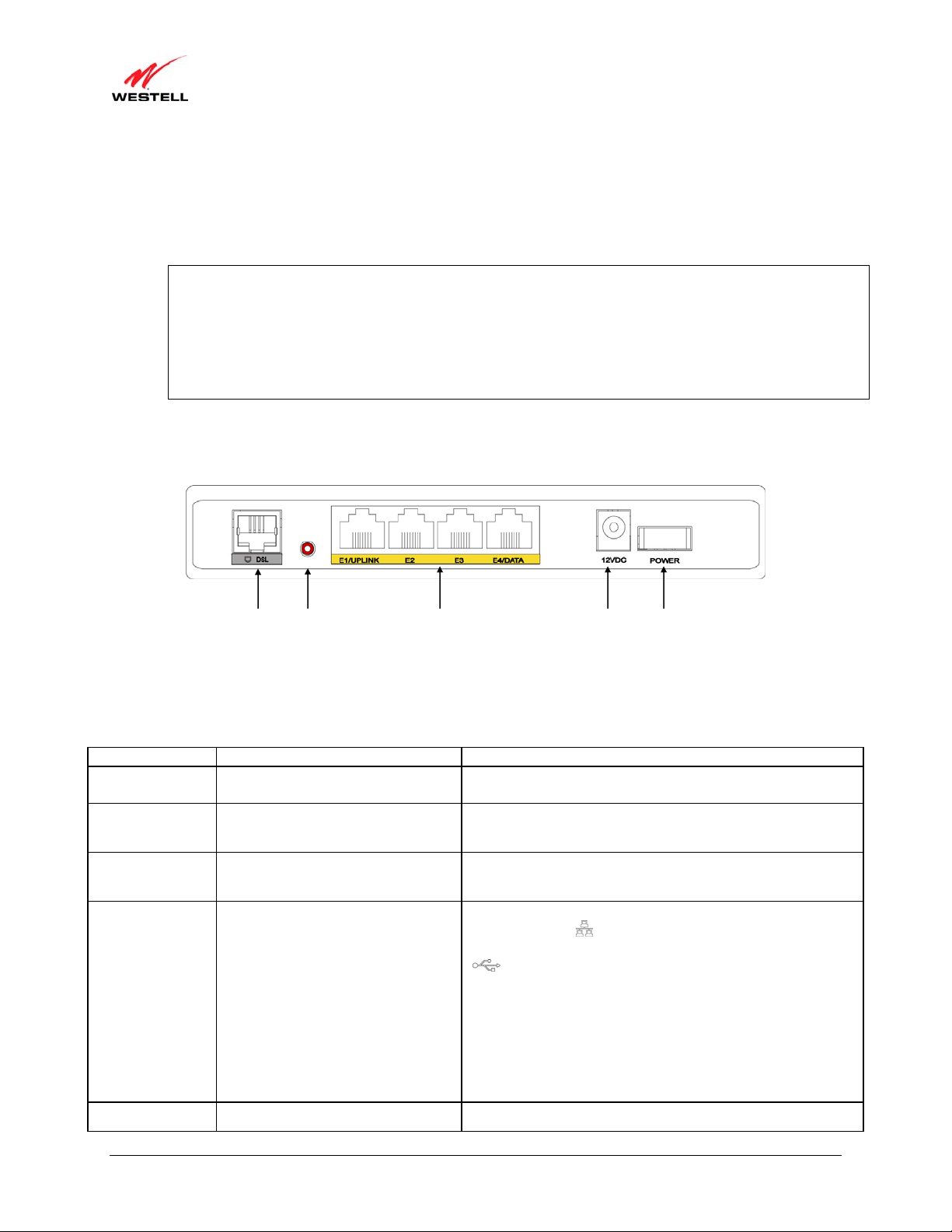
4.2 Cable Connectors and Switch Locations
• DSL connector (RJ-11)
• Reset push button
• Four Ethernet (RJ-45) connectors with optional E1/UPLINK port and optional E4/DATA port
NOTE:
1. When using the optional E1/ UPLINK jack (when Gateway is configured for WAN Uplink mode), Ethernet
LAN connection is limited to ports E2, E3, and E4. The Uplink feature is option a l. If Uplink is not enabled
via the Web pages, your Gateway will use DSL as the WAN interface.
2. If you desire to install your Gateway using a USB cable, use the optional E4/DATA port, which can be
used for either USB or Ethernet installation. Refer to section 5, “Hardware Installations,” for hardware
installation instructions.
• Power connector (12 VDC) barrel
• OFF/ON power switch
Gateway - Rear View
DSL Line
Connector
Reset
Button
Ethernet Connectors
E1/UPLINK E2, E3, E4/DATA
Power
Connector
Off/On
Power Switch
4.3 Connector Descriptions
The following chart displays the Gateway’s connector types.
AME TYPE FUNCTION
N
DSL LINE Modular 6-pin (RJ-11) DSL jack
E1/UPLINK M od ula r 8-pin (RJ-45) Ethernet jack
E2/E3/E4 Modular 8-pin (RJ-45) Ethernet jack
E4/DATA Modular 8-pin (RJ-45) Ethernet jack
POWER Barrel connector Connects the 12 VDC power connector to an AC wall jack.
030-300613 Rev A 9 August 2009
Connects the Gateway to a telephone jack that has active
DSL service or to the DSL port of a POTS splitter.
Connects the Gateway to a PC or Hub via 10/100 BaseT
Ethernet.
Connects the Gateway to a PC or Hub via 10/100 BaseT
Ethernet.
Connects the Y-cable provided with the kit to the 10/100
Base-T Ethernet
DATA port on the rear of the Gateway
and to the Ethernet port on a PC or Hub. The USB connector
built in to the Y-cable also functions through the
Gateway’s E4/DATA port. When the Ethernet connector is
plugged in to the Gateway’s DATA port, the USB cable can
then be plugged in to the USB port on a PC or Hub. Thus, the
Y-cable provides Internet connectivity via Ethernet or USB;
however, both connectors cannot be used sumultaneously. If
both connectors are installed in a PC or Hub at the same time,
only the connector that syncs up first will be used.

)
User Guide VersaLink Wireless Gateway (Model 7500
4.4 Installation Requirements
This section explains the hardware installation procedures for installing your Gateway.
To install the Gateway, you will need the following:
• Active DSL line
• Network Interface Card (NIC) installed in your PC, or
• Available USB port installed in your PC, or
• 802.11 b/g wireless adapter installed in your PC
IMPORTANT: Please wait until you have received notification from your Internet service provider (ISP) that your
DSL line has been activated before installing your Gateway.
4.5 Before You Begin
Make sure that your kit contains the following items:
• Westell VersaLink Gateway
• Power Supply
• Y-cable comprising:
o Built-in 10/100 BaseT Ethernet cable—labeled PC/Ethernet, yellow
o Built-in USB cable—labeled PC/USB, blue
• RJ-11 Phone cable
• CD-ROM containing User Guide in PDF format
4.6 Microfilters
DSL signals must be blocked from reaching each telephone, answering machine, fax machine, computer Modem, or
any similar conventional device. Failure to do so may degrade telephone voice quality and DSL performance. Install
a microfilter if you desire to use the DSL-equipped line jack for telephone, answering machine, fax machine, or
other telephone device connections. Microfilter installation requires no tools or telephone rewiring. Just unplug the
telephone device from the baseboard or wall mount and snap in a microfilter; next, snap in the telephone device.
You can purchase microfilters from your local electronics retailer, or contact the original provider of your DSL
equipment.
030-300613 Rev A 10 August 2009

)
User Guide VersaLink Wireless Gateway (Model 7500
5. HARDWARE INSTALLATIONS
The following instructions explain how to install your Gateway using 10/100 Base-T Ethernet, Wireless, Ethernet
Uplink, or USB connections. Before you begin, please read the following notes:
NOTE:
1. If your Ethernet card does not auto-negotiate, set it to half duplex. Refer to the Ethernet card manufacturer’s
instructions for installing and configuring your Ethernet card.
2. If you are using your Gateway in conjunction with an Ethernet Hub or Switch, refer to the manufacturer’s
instructions for proper installation and configuration.
3. When using a Microfilter, confirm that the DSL RJ-11 phone cable is connected to the DSL port of the DSL/HPN
non-filtered jack.
4. It is recommended that you use a surge suppressor to protect equipment attached to the power supply. Use only
the power supply provided with your kit.
5. Depending on the installation method you are using, additional Ethernet cables may be required. Ethernet cables
and DSL filters can be purchased at your local computer hardware retailer.
6. Your Gateway supports simu ltaneous 10/100 Base-T Ethernet and Wireless configurations. To use this
installation method, follow the instructions provided in sections 5.3.1, “Connecting Ethernet Devices to Your
Gateway,” and 5.3.2, “Networking Wireless Devi ces to Your Gateway.” Your Gateway does not su pp ort
connection via 10/100 Base-T Ethernet and USB simultaneously.
Your Gateway supports two modes for WAN access, which are configurable through your Gateway’s Web pages:
(1) LAN Ethernet port mode and (2) WAN Uplink port mode.
• LAN Ethernet port mode allows you to use your Gateway’s DSL port for WAN access (Gateway’s DSL
functionality is Enabled). In this mode you should install your Gateway according to the instructions in
section 5.1, “Connecting Your Gateway to a DSL Network.”
• WAN Uplink port mode allows you to use your Gateway as an Ethernet gateway (for example, to connect
to a cable modem or to another DSL device that provides WAN access). In WAN Uplink port mode, your
Gateway’s DSL functionality is disabled. In this mode, you should install your Gateway according to the
instructions in section 5.2, “Connecting Your Gateway to a Network via E1/UPLINK.”
030-300613 Rev A 11 August 2009
)
User Guide VersaLink Wireless Gateway (Model 7500
5.1 Connecting Your Gateway to a DSL Network
To connect your Gateway to a network provisioned with active DSL service, please follow these steps:
1. Connect the DSL phone from the connector marked DSL on the rear panel of the Gateway to the telephone wall
jack provisioned with DSL service. Please use the DSL phone cable that was provided with your kit.
IMPORTANT: Plug the RJ-11 DSL phone cable from the Gateway into the DSL port of the microfilter
plugged into the telephone jack at the wall.
2. Plug the small end of the power supply cord into the connector marked 12VDC on the rear panel of the Gateway.
Plug the other end of the power supply into an AC wall socket.
3. Turn on the Gateway (if it is not already on) by pressing the POWER switch on the back of the Gateway.
4. Check to see if the POWER LED is solid green. Solid green indicates that the Gateway is functioning properly.
5. Check to see if the DSL LED is solid green. If it is solid green, DSL is functioning properly.
6. Log on to your account, and establish an Internet connection, as explained later in section 7, “Accessing Your
Gateway.”
7. Check to see if the Gateway’s INTERNET LED is solid green. Solid green indicates that the Internet link has
been established. (Flashing green indicates the presence of IP traffic.)
Congratulations! You have completed the installation. Now, go to section 5.3, “Connecting Other Networking Devi ces to
Your Gateway,” for instructions on connecting other networking devices to your Gateway.
5.2 Connecting Your Gateway to a Network via E1/UPLINK
The Uplink feature is optional. To install your Gateway so that it uplinks to another DSL device, such as an existing
DSL or cable modem installed on your network, please follow these steps:
1. Ensure that your existing DSL or cable modem is properly installed on your network and has active broadband
(Internet) connection.
2. Obtain a 10/100 BaseT Ethernet cable, and plug one end of the cable into the port marked E1/UPLINK on the
rear panel of your Gateway. Then, plug the other end of the Ethernet cable into the Ethernet port on the attached
DSL or cable modem.
If desired, you can use the Y-cable provided with your kit. Simply plug the “Y” end of the cable (Ethernet jack
labeled PC/Ethernet, yellow) into the Ethernet port on your existing DSL or cable modem. Then plug the other
end of the Y-cable (Ethernet jack labeled PC/Ethernet, yellow) into the E1/UPLINK port on the rear panel of
your Gateway.
Later, in your Gateway’s Web pages, be sure to select WAN Uplink port mode to allow your Gateway to uplink
to the existing broadband device. When your Gateway is configured for WAN Uplink port, your Gatew ay’s DSL
transceiver will not be used. The broadband device to which your Gateway is connected will be your WAN
interface to the Internet. LAN Ethernet port is your Gateway’s factory default setting.
3. Plug the small end of the power supply cord into the connector marked 12VDC on the rear panel of the Gateway.
Plug the other end of the power supply into an AC wall socket.
4. Make sure the existing modem on your network is powered on.
5. Turn on the Gateway (if it is not already on) by pressing the POWER switch on the back of the Gateway.
6. Check the front of the Gateway to see if the POWER LED is solid green. Solid green indicates that the Gateway
is powered on.
030-300613 Rev A 12 August 2009
)
User Guide VersaLink Wireless Gateway (Model 7500
7. Check to see if the ETHERNET LED is solid green. Solid green indicates that Ethernet is working properly.
8. Log on to your account, and establish an Internet connection, as explained later in section 7, “Accessing Your
Gateway.”
9. Check to see if the Gateway’s INTERNET LED is solid green. Solid green indicates that the Internet link has
been established. (Flashing green indicates the presence of IP traffic.)
Congratulations! You have completed the installation. Now, go to section 5.3, “Connecting Other Networking Devi ces to
Your Gateway,” for instructions on connecting other networking devices to your Gateway.
5.3 Connecting Other Networking Devices to Your Gateway
Now that you have connected your Gateway to your broadband network, you can connect Ethernet, USB, and
Wireless networking devices to your Gateway, allowing for Internet connection throughout your home without
disrupting your cable or satellite television services. Refer to the following sections for connection and networking
instructions:
• Section 5.3.1, “Connecting Ethernet Devices to Your Gateway,” explains how to connect Ethernet devices
to your Gateway.
• Section 5.3.2, “Networking Wireless Devices to Your Gateway,” explains how to network Wireless devices
to your Gateway.
• Section 5.3.3, “Connecting USB Devices to Your Gateway,” explains how to connect USB devices to your
Gateway.
5.3.1 Connecting Ethernet Devices to Your Gateway
To network computers in your home or office to your Gateway using an Ethern et installation, please follow these
steps:
1. Ensure that you have connected your Gateway to your broadband service using one of the installation methods
explained earlier in sections 5.1, “Connecting Your Gateway to a DSL Network,” and 5.2, “Connecting Your
Gateway to a Network via E1/UPLINK.”
2. Obtain an Ethernet cable. Connect the Ethernet cable from any one of the four Ethernet jacks marked E1, E2,
E3, and E4 on the rear panel of the Gateway to the Ethernet port on your computer. Repeat this step to connect
up to three additional PCs to the Gateway. (If you’re not already using the Y-cable prov ided with your kit, you
can use the Y-cable—the jacks labeled PC/Ethernet, yellow—for this Ethernet installation.
NOTE:
1. If you are networking computers to your Gateway using Ethernet, you can plug in to any of the four LAN
Ethernet jacks on the Gateway’s rear panel; each jack serves as an Ethernet switch.
2. If you are using the E1/UPLINK jack for your broa dband connection, you can network PCs to your Gateway via
Ethernet using jacks E2, E3, or E4.
3. If you are networking a PC to your Gateway using USB, use only the E4/DATA jack on the rear of your
Gateway.
3. Check to see if the Gateway’s ETHERNET LED is solid green. Solid green indicates that the Ethernet
connection is functioning properly. Check the ETHERNET LED for each Ethernet jack to which you are
connected.
Congratulations! You have completed the connection. Now, go to section 7, “Accessing Your Gateway,” to access
your Gateway’s Web pages.
030-300613 Rev A 13 August 2009

)
User Guide VersaLink Wireless Gateway (Model 7500
5.3.2 Networking Wireless Devices to Your Gateway
IMPORTANT: In order to communicate with the Gateway, each PC’s wireless network adapter must be configured
with the same SSID as that of the Gateway. The default SSID for the Gateway is the serial number of the unit
(located on the bottom of the Gateway and also on the shipping carton). The SSID is also provided in the Gateway’s
Web pages, in the Wireless menu. Use this SSID in each connecting PC. Later, for privacy, you can change the
Gateway’s SSID by following the procedures outlined in section 12.1, “Wireless Basic Setup.” Be sure to change
the SSID in the connecting PCs as well, so that they always match the Gateway’s SSID.
1. Client PCs can use any Wireless 802.11b/g certified card to communicate with your Gateway.
2. Configuring the Gateway so that it hides its SSID offers some security benefits—by reducing the Gateway’s
visibility. If the Gateway’s SSID is hidden, each wireless station will need to be manually configured to match
the Gateway’s SSID in order to connect to the network. When the Gateway’s SSID is not hidden, then the SSID
will show up when the PC displays the list of available networks. (By factory default, the Gateway’s SSID is
displayed in the Wireless Basic Setup screen; “Hide SSID” is disabled.)
3. The wireless network connection utility on most PCs can automatically determine the availability of the Gateway
and its security type. The utility typically displays a list of available networks that are in range. By selecting the
network and clicking connect, yo u should get a screen prompting you for the security key.
4. If you are configuring the wireless station manually, the Wireless card and Gateway must use the same security
code type. If you use WPA or WEP wireless security, you must configure your computer’s wireless adapter for
the security type and security key that you use. Consult the wireless adapter’s manual for instructions on
configuring the security parameters.
To network computers in your home or office to your Gateway using a wireless installation, please follow these
steps:
1. Ensure that you have connected your Gateway to your broadband service using one of the installation methods
explained earlier in sections 5.1, “Connecting Your Gateway to a DSL Network,” or 5.2, “Connecting Your
Gateway to a Network via E1/UPLINK.”
2. Ensure that wireless operation in the Gateway is Enabled. Refer to section 12, “Wireless,” for details.
3. Make sure each PC on your wireless network has an 802.11b/g wireless network adapter installed.
4. Ensure that the appropriate drivers for the wireless adapter have been installed on each PC.
5. Locate and run the utility software provided with your PC’s wireless network adapter. If needed, refer to the
wireless adapter manufacturer’s instructions.
6. Check to ensure that the wireless adapter is using the identical SSID as the one used in your Gateway.
7. Ensure that the wireless adapter is using the identical security keys as the ones used in your G a teway (if you are
using wireless security in your Gateway).
8. Check to see if the Gateway’s WIRELESS LED is solid green. This means that the Gateway’s Wireless
interface is functioning properly.
9. Check to see if the connecting PC has established a wireless connection; your wireless utility should indicate
that you have a wireless signal. (You might need to wait a brief moment for the PC to connect to the Gateway.)
Congratulations! You have completed the connection. Now, go to section 7, “Accessing Your Gateway,” to access
your Gateway’s Web pages.
030-300613 Rev A 14 August 2009
)
User Guide VersaLink Wireless Gateway (Model 7500
5.3.3 Connecting USB Devices to Your Gateway
It is recommended that you connect your Gateway via Ethernet connections. However, if you choose to connect
your computer via USB, please follow the instructions in this section.
IMPORTANT: The USB installation will not function for Macintosh computers. Macintosh users will need to
install the Gateway via Ethernet connection. Refer to section 5.3.1, “Connecting Ethernet Devices to Your
Gateway,” for Ethernet installation instructions.
To network a computer in your home or office to your Gateway using a USB connection, please follow these steps:
1. Ensure that you have connected your Gateway to your broadband service using one of the installation methods
explained earlier in sections 5.1, “Connecting Your Gateway to a DSL Network,” or 5.2, “Connecting Your
Gateway to a Network via E1/UPLINK.”
2. Insert the CD-ROM provided with your kit into the CD-ROM drive of the PC that will connect via USB.
3. Use the Y-cable provided with your kit. At the “Y” end of the cable, plug the USB jack (labeled PC/USB, blue)
into the USB port on your computer. Then, at the other end of the Y-cable, plug the Ethernet jack (labeled
PC/ETHERNET, yellow) into the Ethernet connector marked E4/DATA on the rear panel of the Gateway.
NOTE:
1. If you are networking a PC to your Gateway using USB, use only the E4/DATA jack on the rear of your
Gateway.
2. If you are using the E1/UPLINK jack for your broa dband connection, you can network PCs to your Gateway via
Ethernet using jacks E2, E3, or E4.
3. If you are networking computers to your Gateway using Ethernet, you can use any of the four LAN Ethernet
jacks on the Gateway’s rear panel; each jack serves as an Ethernet switch.
4. Plug the small end of the power supply cord into the connector marked 12VDC on the rear panel of the
Gateway. Plug the other end of the power supply into an AC wall socket, and then turn on the Gateway (if it is
not already on) by pressing the POWER switch on the back of the Gateway.
5. Complete the instructions outlined in section 6, “Installing the USB Drivers.” Then, return to this section to
complete the remaining step.
6. After the USB drivers have been installed, check to see if the USB LED is solid green. Solid green indicates that the
USB connection is functioning properly.
Congratulations! You have completed the USB hardware installation. Now, go to section 7, “Accessing Your
Gateway,” to access your Gateway’s Web pages.
030-300613 Rev A 15 August 2009
)
User Guide VersaLink Wireless Gateway (Model 7500
6. INSTALLING THE USB DRIVERS
This section explains how to install the USB drivers for your Gateway. If you are using only an Ethernet connection,
USB driver installation is not necessary. The Microsoft Plug and Play (PnP) auto-detect feature recognizes when
new hardware has been installed. After you connect the Gateway to the PC, the Gateway will be detected
automatically.
IMPORTANT: Make sure that the CD-ROM provided with your kit is inserted into the PC’s CD-ROM drive before
connecting the USB jack, as explained in section 5.3.3, “Connecting USB Devices to Your Gateway.”
Determine which operating system is installed on your PC, and then follow the USB driver instructions that match
your operating system. The following table provides a reference to the USB driver installation instructions. After
you have completed the USB driver installation, return to section 5.3.3, “Connecting USB Devices to Your
Gateway,” to complete the USB hardware installation instructions.
Your Operating System Refer to this section for USB driver instructions
Windows 2000 6.1. Installing the USB Driver for Windows 2000
Windows XP 6.2. Installing the USB Driver for Windows XP
Windows Vista™ 6.3. Installing the USB Driver for Windows Vista™
6.1 Installing the USB Driver for Windows 2000
To install the USB driver for Windows 2000, please follow these steps:
IMPORTANT: Confirm that the CD-ROM provided with the Gateway kit is inserted into the PC’s CD-ROM drive
before beginning this installation.
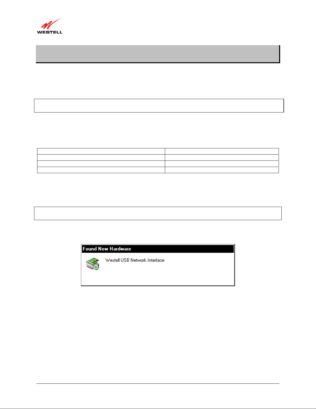
1. Windows 2000: After you connect the Gateway to your PC, the Found New Hardware window will appear
(Figure 1). After a brief delay, the Found New Hardware Wizard will appear (Figure 2). Click Next.
Figure 1. Windows 2000
030-300613 Rev A 16 August 2009
)
User Guide VersaLink Wireless Gateway (Model 7500
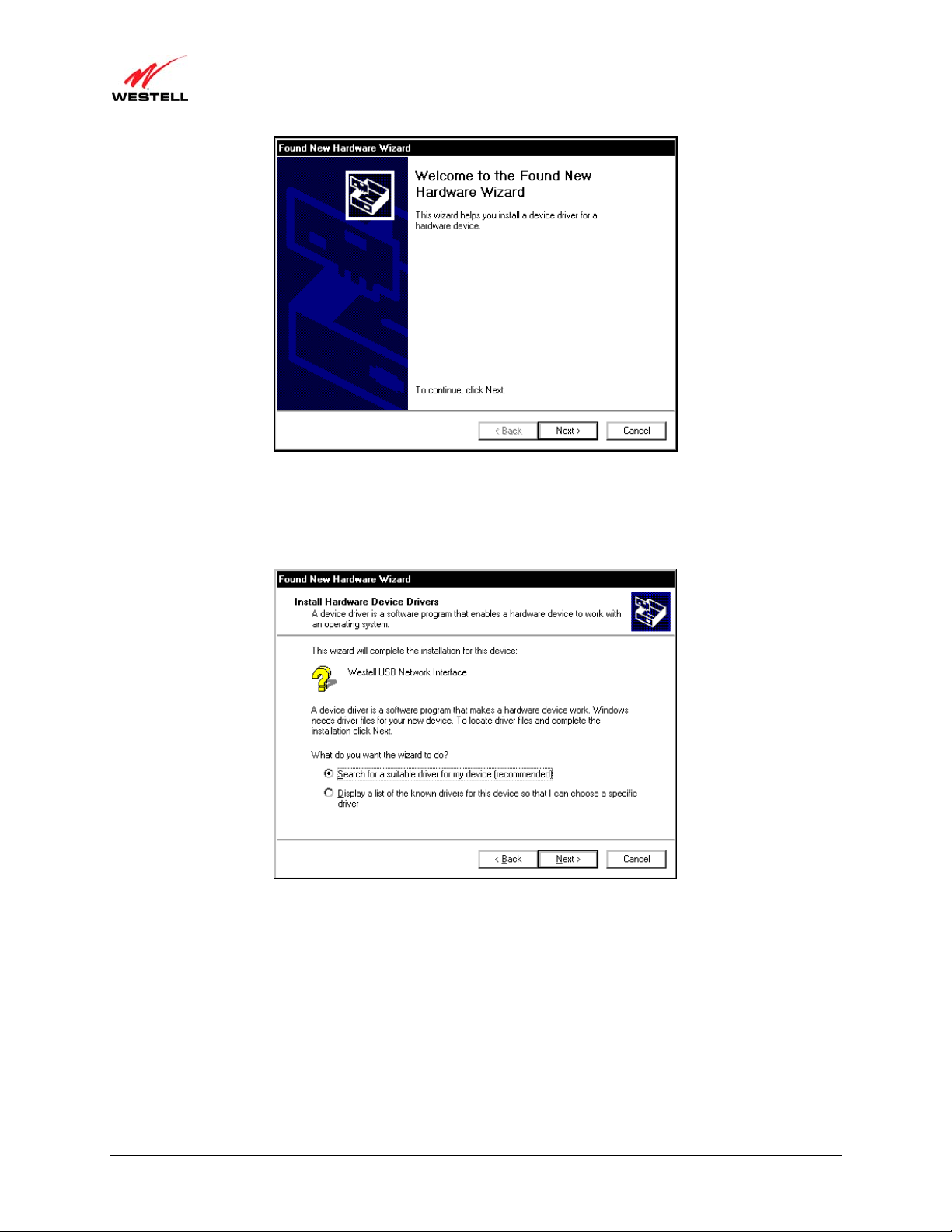
2. Windows 2000: The Install Hardware Device Drivers window will appear (Figure 3). Select Search for a
suitable driver for my device (recommended). Click Next.
Figure 2. Windows 2000
Figure 3. Windows 2000
030-300613 Rev A 17 August 2009
)
User Guide VersaLink Wireless Gateway (Model 7500
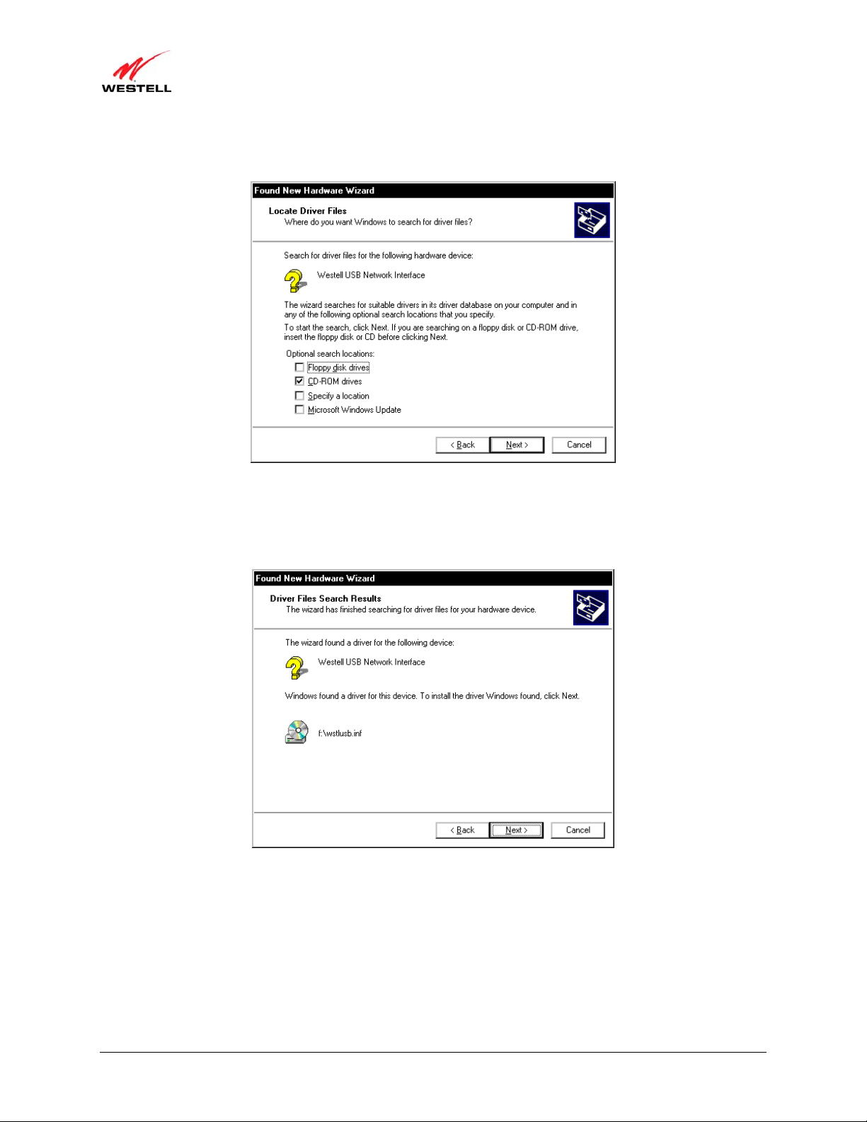
3. Windows 2000: The Locate Driver Files window will appear. Select CD-ROM drives (Figure 4). Click Next.
Figure 4. Windows 2000
4. Windows 2000: The Driver Files Search Results window will appear (Figure 5). Note the drive “letter” may
vary. Click Next.
Figure 5. Windows 2000
030-300613 Rev A 18 August 2009
)
User Guide VersaLink Wireless Gateway (Model 7500
5. Windows 2000: The window below confirms that the PC has finished loading the drivers (Figure 6). Click
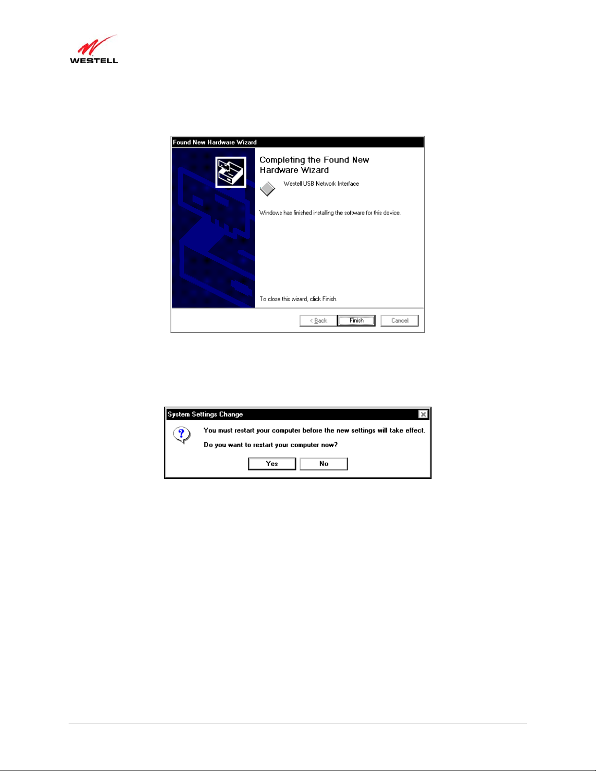
Finish.
Figure 6. Windows 2000
6. Windows 2000: When the System Settings Change screen appears, the USB d rivers are installed properly
(Figure 7). Click Yes to restart your computer.
Figure 7. Windows 2000
Congratulations! You have completed the software installation for the USB drivers. Now, return to section 5.3.3,
“Connecting USB Devices to Your Gateway,” to complete the hardware installation instructions.
030-300613 Rev A 19 August 2009
)
User Guide VersaLink Wireless Gateway (Model 7500
6.2 Installing the USB Driver for Windows XP
To install the USB driver for Windows XP, please follow these steps:
IMPORTANT: Confirm that the CD-ROM provided with the Gateway kit is inserted into the PC’s CD-ROM drive
before beginning this installation.
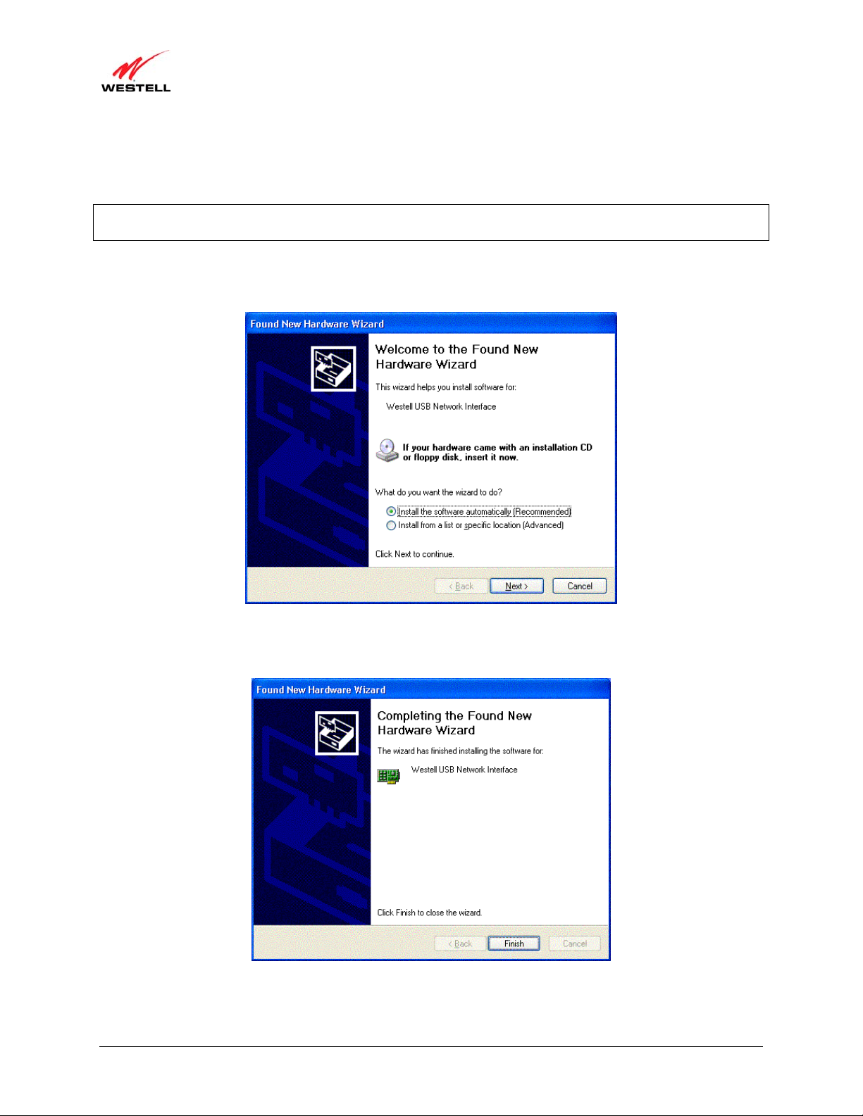
1. Windows XP: After you connect the Gateway to your PC, the following screen will appear (Figure 8). Select
Install the software automatically (Recommended). Click Next.
Figure 8. Windows XP
2. Windows XP: The window below confirms that the PC has finished loading the drivers (Figure 9). Click Finish.
Figure 9. Windows XP
Congratulations! You have completed the software installation for the USB drivers. Now return to section 5.3.3,
“Connecting USB Devices to Your Gateway,” to complete the hardware installation instructions.
030-300613 Rev A 20 August 2009
)
User Guide VersaLink Wireless Gateway (Model 7500
6.3 Installing the USB Driver for Windows Vista™
To install the USB driver for Windows Vista™, please follow these steps:
IMPORTANT: Confirm that the CD-ROM provided with the Gateway kit is inserted into the PC’s CD-ROM drive
before beginning this installation.
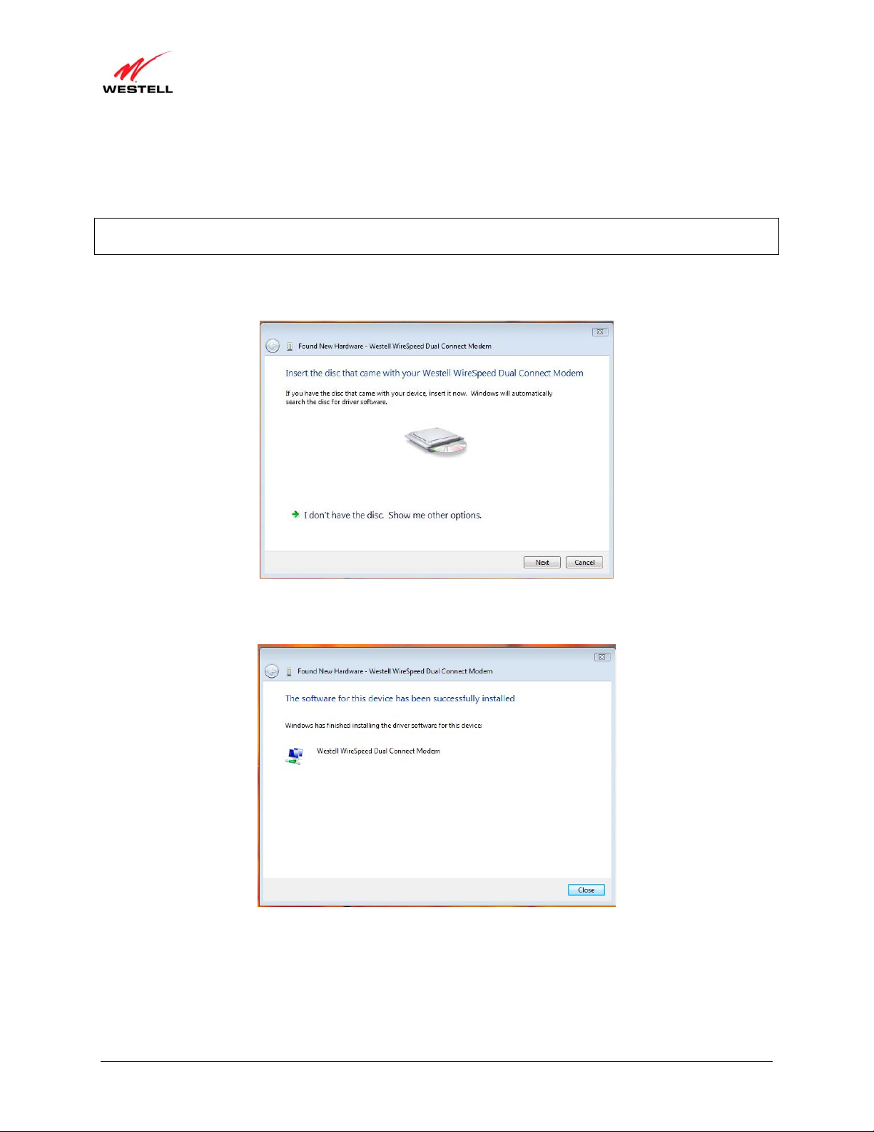
1. Windows Vista™: After you connect the Gateway to your PC, the following Found New Hardware screen
will appear (Figure 10). Click Next.
Figure 10. Windows Vista
2. Windows Vista™: The window below confirms that the PC has finished loading the drivers (Figure 11). Click
Close.
Figure 11. Windows Vista
Congratulations! You have completed the software installation for the USB drivers. Now return to section 5.3.3,
“Connecting USB Devices to Your Gateway,” to complete the hardware installation instructions.
030-300613 Rev A 21 August 2009
)
User Guide VersaLink Wireless Gateway (Model 7500
7. ACCESSING YOUR GATEWAY
7.1 Logging on to Your Gateway
This section explains the logon procedures for your Gateway. These procedures should be used any time you want to
access or make changes to your Gateway’s configurations or firewall settings.
IMPORTANT: Your Gateway is capable of automatically sensing protocol type (DHCP or PPPoE). Th is process is
designed to start after you have connected your Gateway to your network. To access your Gateway’s Web pages,
your PC must be configured for DHCP. Refer to your Windows help screen for information on configuring your
computer for DHCP. At your PC, click Start, then Help to access the Windows help screen.
Your ISP determines the type of protocol you will use to connect to the Internet. Routed IP allows you to connect to
your ISP equipment without first having to identify yourself (authenticate) with your ISP. PPPoE requires that you
authenticate (type an account ID and password) before obtaining an Internet connection. After automatic protocol
detection starts, the Gateway will determine which protocol you will use for your Internet connection.
To log on to your Gateway, start your Web browser, and type the following IP address in th e browser’s address bar:
http://192.168.1.1
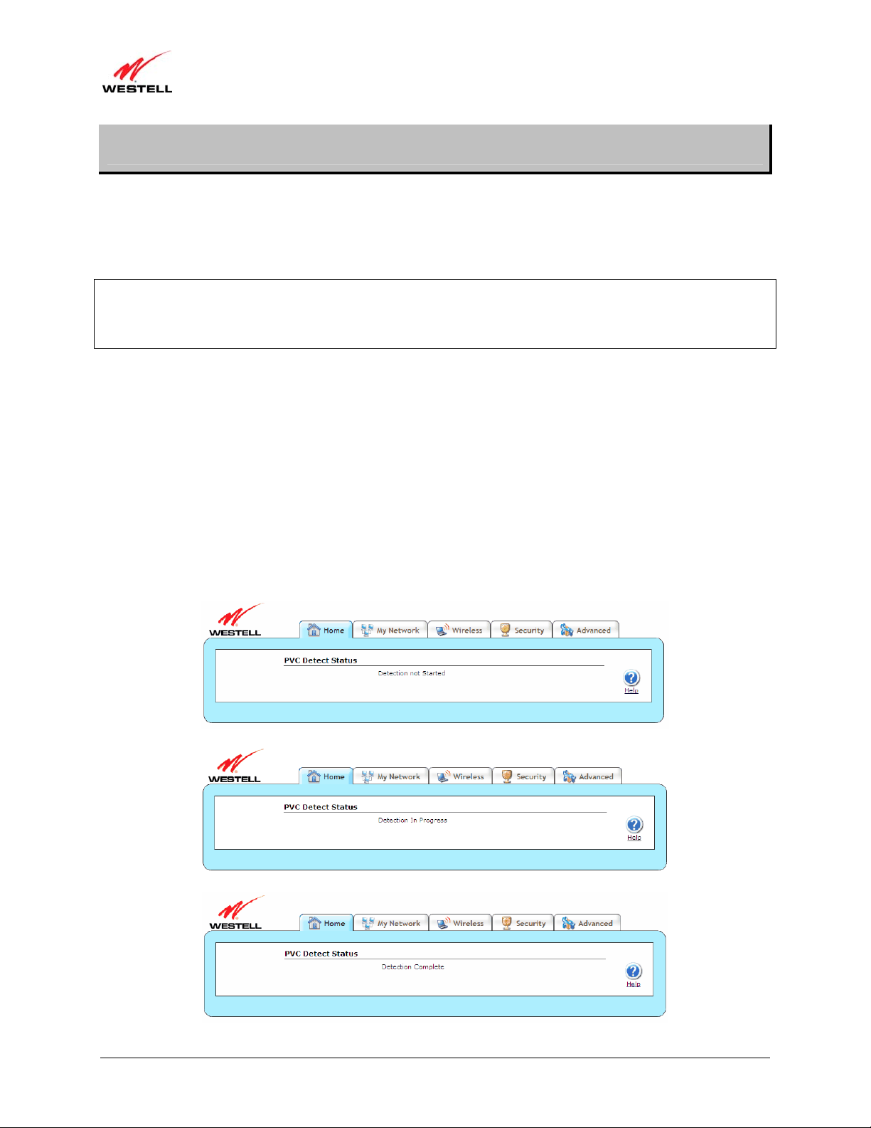
After you have typed the URL address, press Enter on your keyboard. If your Gateway has the Automatic PVC
Detection feature enabled (optional), you will see this screen while the Gateway detects and configures the WAN
connection.
The detection process will then begin as shown in the following screen.
Once the detection process is complete, you will see the following screen.
030-300613 Rev A 22 August 2009

)
User Guide VersaLink Wireless Gateway (Model 7500
7.1.1 Connecting to the Internet via Routed IP Protocol
If Automatic WAN Protocol Detection finds that your ISP’s server is DHCP, the ISP’s DHCP server will send your
Gateway a WAN IP address. A WAN IP address indicates that you have established a connection with your ISP.
Routed IP allows you to connect to your ISP equipment without first having to identify yourself (authenticate) with
your ISP. Once your Gateway has obtained a WAN IP address, you do not need to configur e any additional settings
Congratulations! You have completed the Gateway’s Automatic WAN Protocol Detection process. Now, go to
section 7.4, “Confirming Your Internet Connection,” to confirm your Internet connection.
NOTE: If you want to modify your Routed IP settings, go to section 14.4.3, “VersaPort.” The Gateway’s factory
default protocol is Routed IP.
7.1.2 Connecting to the Internet via PPPoE Protocol
Some ISPs require that you identify yourself using PPP (Point-to-Point Protocol) authentication be fore obtaining an
Internet connection. To connect to the Internet for the first time via PPP, go to one of the following sections:
• Section 7.2, “Configuring Your Internet Connection Using the Installation Wizard,” for details on
connecting to the Internet using the Gateway’s built-in Installation Wizard. Use this method for simple,
less-detailed configuration process.
• Section 7.3, “Configuring Your Internet Connection Manually,” for details on connecting to the Internet
using a manually set up connection. Use this method for a more detailed configuration process.
7.2 Configuring Your Internet Connection Using the Installation Wizard
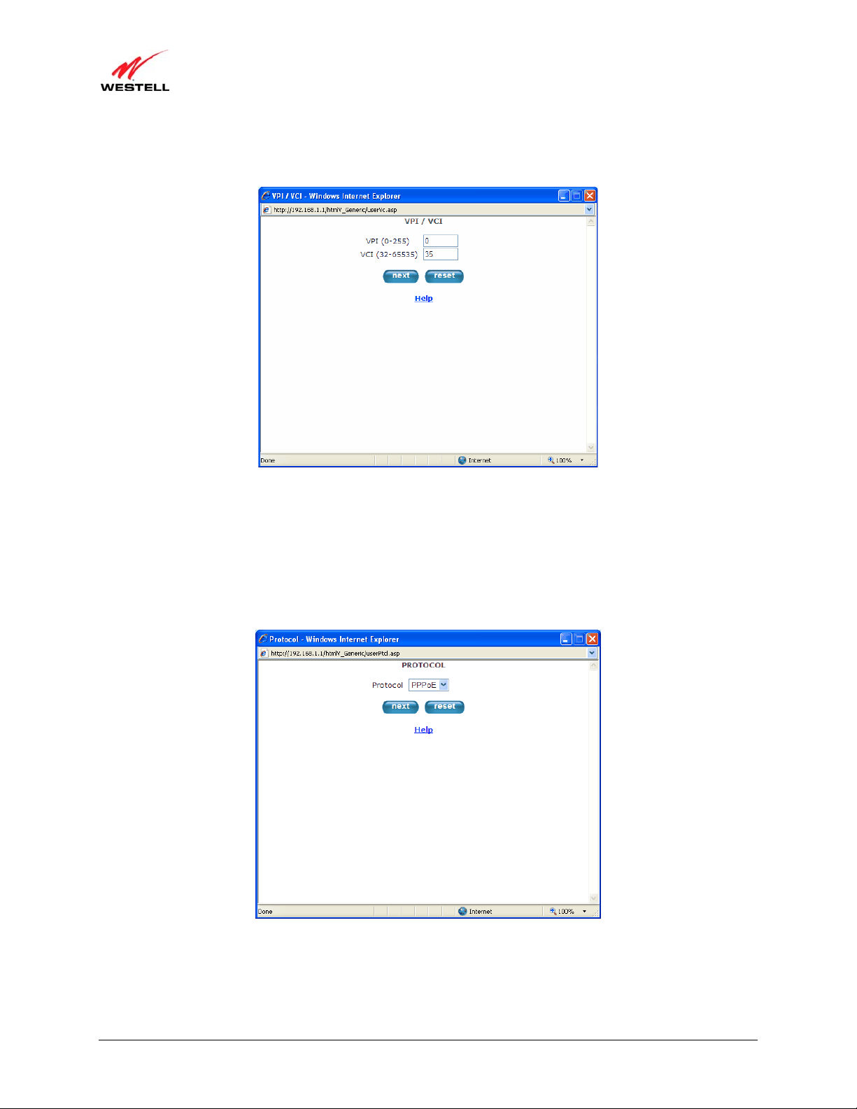
To connect to the Internet using the Gateway’s built-in Installation Wizard, please follow these steps:
1. Click the Add/Edit Connection
Started window will appear.
link in the Broadband Connection panel of the Home screen. The Getting
030-300613 Rev A 23 August 2009
)
User Guide VersaLink Wireless Gateway (Model 7500
2. Click next. The User Name window will appear, requesting information that will allow the Gateway to make a
connection to your ISP. This information is stored in your Gateway.
3. Type in the following information in the fields provided:
• Connection Name: This is a description of the default connection profile that your Gateway will use.
You may use the default or assign a new description.
• Account ID: This is supplied by your ISP. This is a text string which uniquely identifies you with your
ISP.
• Account Password: This is supplied by your ISP. This is a key phrase or text string that verifies your
identity to the ISP.
030-300613 Rev A 24 August 2009
)
User Guide VersaLink Wireless Gateway (Model 7500
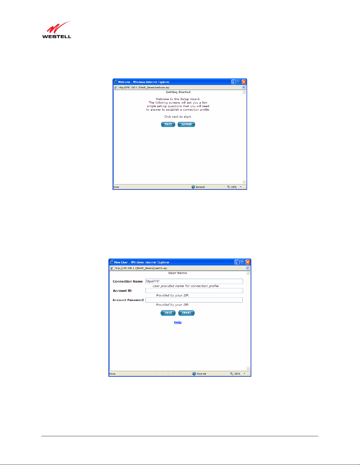
4. Click next. The VPI/VCI window will appear, requesting information that will allow the Gateway to establish a
communications channel to the ISP.
5. Type in the following information in the fields provided:
• VPI (0-255): This is Virtual Path Indicator. This value is supplied by your ISP.
• VCI (32-65535): This is the Virtual Channel Indicator. This value is supplied by your ISP.
6. Click next. The PROTOCOL window appears, requesting a networking protocol to use when communicating
with the ISP.
7. Click the drop-down menu to select a protocol: PPPoA, PPoE, or Bridge. This information is provided by your
ISP.
030-300613 Rev A 25 August 2009
)
User Guide VersaLink Wireless Gateway (Model 7500
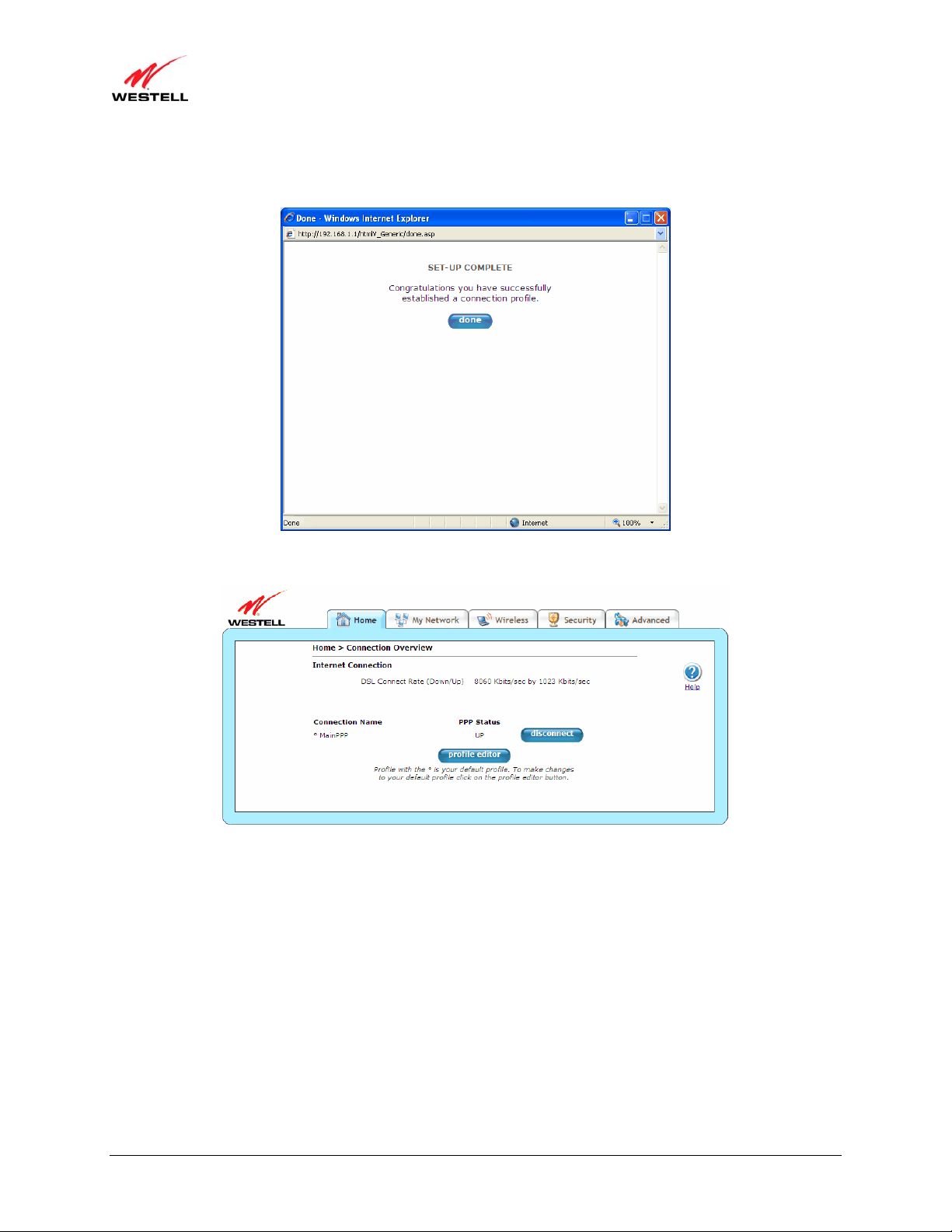
8. Click the next button. The SET-UP COMPLETE window will appear, signifying that you have successfully
established a connection profile.
9. Click the done button. The Connection Overview screen appears. The Installation Wizard is now done.
10. Click Home in the main menu to exit the process completely.
Congratulations! You have com pl eted configuring your Internet connection using the Installation Wizard. Now, go
to section 7.4, “Confirming Your Internet Connection,” to confirm your Internet connection.
030-300613 Rev A 26 August 2009
)
User Guide VersaLink Wireless Gateway (Model 7500
7.3 Configuring Your Internet Connection Manually
Your Gateway allows you to set up connection profiles for PPP authentication with your ISP. A connection profile
contains your account ID and password (provided by your ISP), and several connection options that you can specify
for your profile. The account ID and password are used for each connection profile that you set up. Connection
profiles can be associated with specific service settings, such as firewall settings or NAT services, enabling you to
customize your Gateway for specific users.
IMPORTANT: Before setting up a connection profile, confirm that you have an Account ID and Account Password
from your ISP.
To connect to the Internet manually by setting up a PPPoE connection profile, please follow these steps:
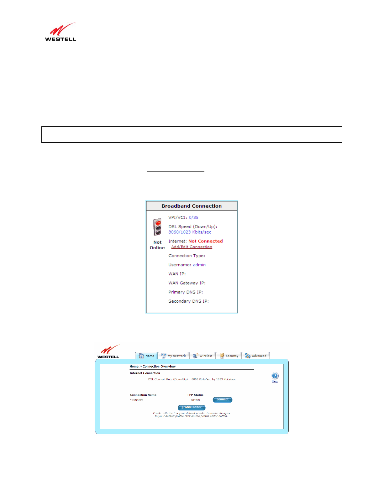
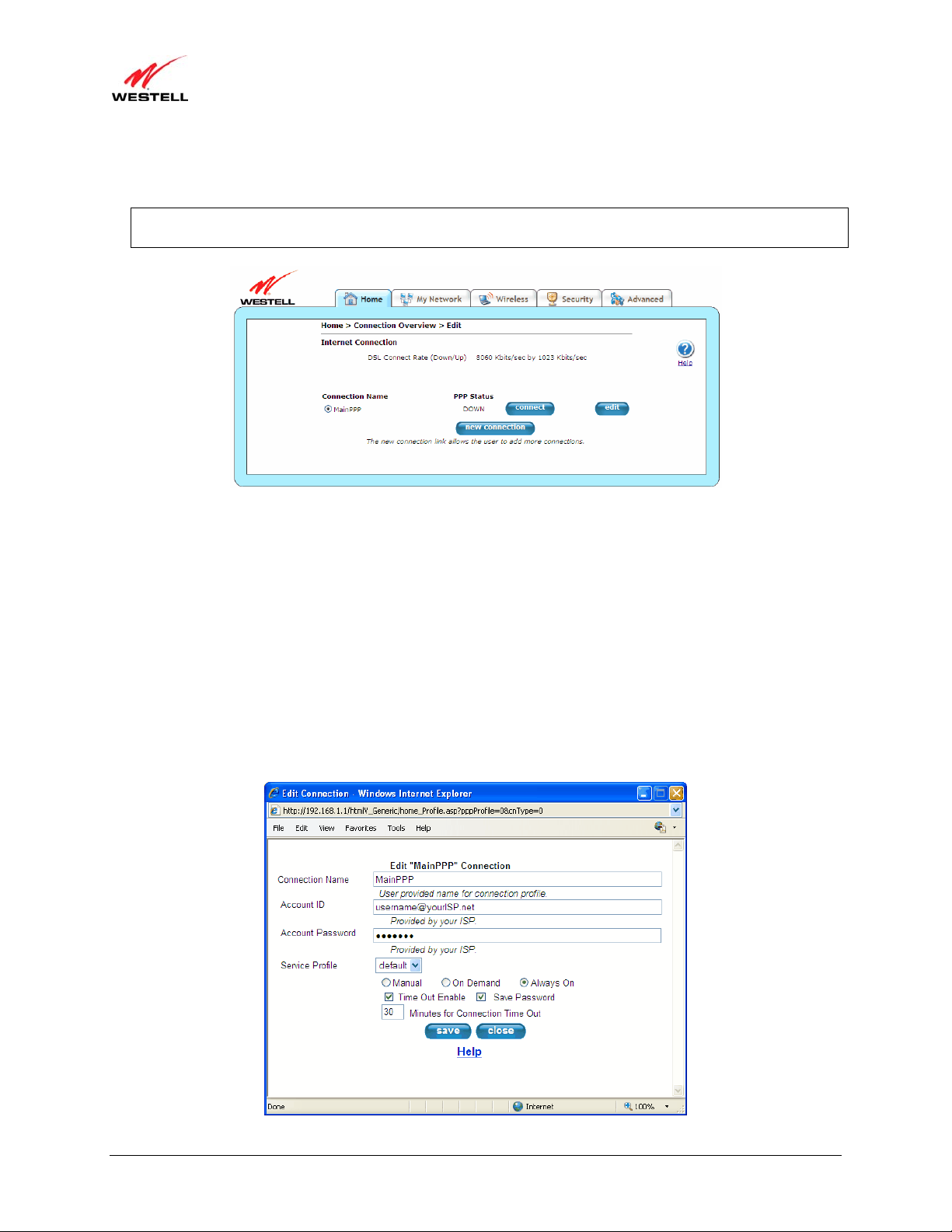
1. Go to the Home page, and click the Add/Edit Connection
Connection Overview screen. The Connection Overview screen displays the status of your Internet
connection. In the screen below, the status displays DOWN. This means that you do not have an Internet
connection.
link in the Broadband Connection to go to the
2. Click profile editor to set up your connection profile. The Edit screen (Home > Connection Overview) will
appear.
030-300613 Rev A 27 August 2009
)
User Guide VersaLink Wireless Gateway (Model 7500
3. Click edit. The Edit Connection window will appear. This window allows you to change the connection profile
settings defined in the Gateway.
NOTE: To create an entirely new connection profile, rather than edit an existing one, click new connection
instead of edit.
4. Type in the following information in the fields provided and select from the following options:
• Connection Name: This is description for the connection profile that your Gateway will use. This name
is supplied by your ISP.
• Account ID: This is your account ID. This ID is supplied by your ISP.
• Account Password: This is your account’s password. This password is provided by your ISP.
• Service Profile: This drop-down menu lists pre-defined Service Profi le s.
• Manual/On Demand/Always On: These are options for specifying how this particular connection
profile is used.
• Time Out Enable: This check box enables/disables an automatic Gateway inactivity timeout.
• Save Password: This check box to enables/disables automatic password entry.
• Minutes for Connection Time Out: This is the number of minutes specified before the Time Out
Enable feature disconnects the Gateway from the ISP.
030-300613 Rev A 28 August 2009

)
User Guide VersaLink Wireless Gateway (Model 7500
Refer to the following table for detailed information on each of the Edit/New Connection window fields.
Connection Name Displays the description for the connection profile that your Gateway will use. This
field allows you to type in the desired name that you want to use for each profile that
you set up. You can create and store up to eight unique connection profiles in your
Gateway, which you can use once you establish a PPP session with your ISP. This
field allows a maximum of 64 characters. Remember, use MainPPP as the connection
name if you are connecting for the first time.
Note: When you establish a PPPoE session for the first time, you must use the factory
default Connection Name “MainPPP” to connect to your ISP. Then, if you want set
up additional profiles, you can use connection names of your choice. The Connection
Name is the name associated each connection profile.
Account ID Displays your Account ID as supplied by your ISP. The Account ID field allows a
maximum of 255 characters.
Account Password
Displays your Account Password as provided by your ISP. The Account Password is
masked for extra security. This field allows a maximum of 255 characters.
Service Profile Click this drop-down menu to select a pre-defined Service Profile. A service profile is
a collection of settings for the built-in firewall and NAT. These settings control which
applications are enabled to communicate through the Gateway. This selection
specifies which service profile is used with this connection.
Manual/On
Demand/Always On
Select the option to specify how this connection profile is used. By default, the
Gateway’s connection setting is set to Always On.
• Manual: Select this option to manually establish your PPP session.
• On Demand: Select this option to automatically reestablish your PPP session
on demand anytime your PC requests Internet activity (for example,
browsing the Internet, email, etc.). Please note that when you have Internet
traffic, this setting may cause a delay.
• Always On: Select this option to automatically establish a PPP session when
you log on or if the PPP session goes down.
Time Out Enable Click this check box to enable disconnect timeout. If enabled, the Gateway will
monitor the ISP connection for activity. If there is no activity for the time out period,
the Gateway will disconnect from the ISP.
Note: The timeout option will be dimmed if you select Always On as your
connection setting.
Save Password Click this check box to enable automatic password entry. If enabled, the Gateway will
automatically insert your Account Password. By default, this feature is enabled
(checked).
Minutes for Connection
Time Out
Displays the number of minutes of inactivity before your gateway will disconnect
from the ISP.
5. Click save and then OK to save the connection settings.
Congratulations! You have completed setting up your PPPoE connection profile. Now, go to section 7.4,
“Confirming Your Internet Connection,” to confirm your Internet connection.
030-300613 Rev A 29 August 2009
)
User Guide VersaLink Wireless Gateway (Model 7500
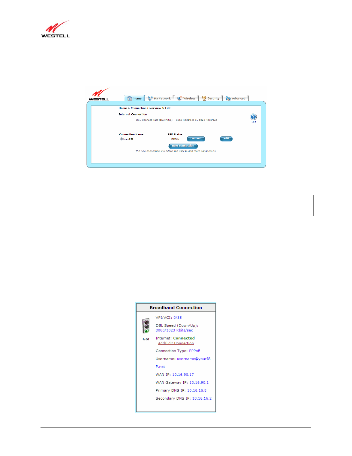
7.4 Confirming Your Internet Connection
If you clicked the Save button in the Edit or New Connection window, the following screen will appear.
Click the Connect button, and wait a brief moment while the Gateway connects to the Internet. The Status field will
display UP once an Internet connection has been established.
NOTE: If your Gateway’s connection setting is set to Always On or On Demand, after a brief delay, the Internet
connection will be established automatically; however, if the connection setting is set to Manual, you must click the
Connect button in the Connection screen to establish an Internet connection.
Additional ways to confirm your Internet connection are:
• In the Broadband Connection panel of the Home page, vi ew the Internet field. If the status reads Not
Connected, you do not have a DSL link. However, if the Internet field displays Connected and the Speed
(Down/Up) field displays numeric values, a DSL link has been established. The values displayed represent
the transmission rates of your DSL signal (downstream and upstream). You may need to wait a brief
moment for the Gateway to report these valu es.
• At the top of the Gateway, check to see if the DSL LED is solid green. Solid green indicates that the
Gateway’s DSL connection has been established. (The DSL LED may flash while the connection is being
established.) Please wait a brief moment for the Gateway to connect.
030-300613 Rev A 30 August 2009

)
User Guide VersaLink Wireless Gateway (Model 7500
If you do not have a DSL sync, first check your physical connections. (Refer to section 5, “Hardware Installations,”
if needed.) If the problem persists, contact your ISP for further instructions.
Congratulations! You have established an Internet connection. You can now Go! browse the Internet. For example, to
visit Westell’s home page, type http://www.westell.com in your Internet browser’ s address bar, and then press Enter
on your keyboard.
7.5 Disconnecting from an Internet Session
If you have finished browsing the Internet and want to disconnect from your ISP, click the Add/Edit Connection
link from the Broadband Connection panel. The following Home > Connection Overview screen will appear.
Click disconnect and then OK.
IMPORTANT: If you disconnect the PPP session, this will disconnect the Gateway from the Internet, and Internet
access for all users connected to the Gateway will be down until the PPP session is re-established.
If you clicked the disconnect button in the Home > Connection Overview screen, after a brief moment, PPP
Status should display DOWN. This means that you no longer have a PPP session. However, your DSL session will
not be affected. When you are ready to end your DSL session, simply turn o ff the Gateway via the POWER switch
on the Gateway’s rear panel.
When you are ready to establish a PPP session again, click the connect button in the Home > Connection
Overview screen. If you have previously turned off the Gateway, first turn on the Gateway, and then log on to your
account profile to establish a PPP session.
030-300613 Rev A 31 August 2009

)
User Guide VersaLink Wireless Gateway (Model 7500
NOTE: When you are ready to exit the Gateway’s interface, click on the X (close) in the upper-right corner of the
browser window. This will not affect your PPP Status; i.e., your PPP session will not be disconnected. You must
click the disconnect button to disconnect your PPP session. To restore this interface, open your Internet browser
window, type http://192.168.1.1/ in the browser’s address bar, and then press Enter on your keyboard. Type your
User name and Password in the pop-up screen as needed.
7.6 Changing the Administration Password
It is recommended that you change the administration password of your Gateway after completing initial installatio n
and setup. You can accomplish this through the Change Password screen (Security > Change Password). This
screen allows you to change the default administration name and password to values of your choice.
IMPORTANT:
1. The Security > Change Password screen allows you to use admin as your administrator name (your
administrator name can match yo ur user name). However, you may not use password as your administrator
password. The values in these fields are case sensitive. Once you decide on an administrator name and password,
please record them for future reference.
2. This feature changes the Administrator’s password, not the PPP password.
Type your Administration Name and your Administration Password in the fields provided, and then click change
and OK. The password fields will be masked for security purposes.
Type a new password.
(Do not type the word
password here.)
If you clicked OK after clicking change, the following screen will appear. Type in your new User name and
Password in the fields provided, and then click OK.
Type admin or
the name of
your choice.
030-300613 Rev A 32 August 2009

)
User Guide VersaLink Wireless Gateway (Model 7500
8. SETTING UP MACINTOSH OS X
This section provides instructions on how to use Macintosh Operating System 10 with the Gateway. Follow the
instructions in this section to create a new network configuration for Macintosh OS X.
NOTE: Macintosh computers must use the Gateway’s Ethernet installation. Refer to section 5, “Hardware
Installations,” for details.
8.1 Opening the System Preference Screen
After you have connected the Gateway to the Ethernet port of your Macintosh, the screen below will appear. Click
the Apple icon in the upper-left corner of the screen, and select System Preferences.
8.2 Choosing the Network Preferences
After selecting System Preferences from the previous screen, the following screen will appear. Click the Network
icon.
030-300613 Rev A 33 August 2009

)
User Guide VersaLink Wireless Gateway (Model 7500
8.3 Creating a New Location
After clicking the Network icon, the following screen will appear. Select New Location from the Location field.
8.4 Naming the New Location
After selecting New Location in the Network screen, the following screen will appear. In the field labeled
Name your new location:, change the text from Untitled to Westell. Click OK.
8.5 Selecting the Ethernet Configuration
After clicking OK in the Name your new location: screen, the Network screen will appear. The Network screen
displays the settings for the newly created location. From th e Configure field in the Network screen, select Built-in
Ethernet. Click Save to save the settings.
NOTE: Default settings for the Built-in Ethernet configuration are sufficient to operate the Gateway.
030-300613 Rev A 34 August 2009

)
User Guide VersaLink Wireless Gateway (Model 7500
8.6 Checking the IP Connection
To verify that the computer is communicating with the Gateway, please follow these steps:
1. Go to the Apple icon in the upper-left corner of the screen, and select System Preferences.
2. In the System Preferences screen, click the Network icon. The Network screen will appear.
3. In the Configure field in the Network screen, select Built-in Ethernet.
4. View the IP address field. An IP address that begins with 192.168.1 should appear.
Congratulations! You have successfully verified communication between the computer and Gateway. Now, go to
section 8.7, “Accessing Your Gateway,” to access your Gateway’s Web pages.
NOTE: The Gateway’s DHCP server provides this IP address. If this IP address is not displayed, check the
Gateway’s wiring connection to the PC. If necessary, refer to section 5, “Hardware Installations,” for instructions.
8.7 Accessing Your Gateway
In your Internet Explorer Web browser ad dress bar, type http://192.168.1.1/. Next, press Enter on your keyboard.
030-300613 Rev A 35 August 2009

)
User Guide VersaLink Wireless Gateway (Model 7500
The Modem Secure screen will appear. Go to the Modem Secure screen in section 7.1, “Logging on to Your
Gateway,” for logon instructions.
030-300613 Rev A 36 August 2009

)
User Guide VersaLink Wireless Gateway (Model 7500
9. BASIC CONFIGURATION
IMPORTANT: The following sections assume that you have active DSL and Internet service.
Your Gateway allows you to make changes to the configurable features of your Gateway, such as account profiles,
routing configurations, wireless settings, and security settings. The following sections explain each feature and show
you how to make changes to the Gateway’s settings. The main menu, displayed at the top of each page, allows you
to navigate to the various configuration screens of your Gateway. Wh enever you change the conf igurable settin gs of
your Gateway, you must click save (or apply where applicable) to allow the changes to take effect in the Gateway.
To configure the settings in your Gateway, follow the instructions provided in sections 10 through 14.
NOTE: The menu options displayed will vary according to the configuration you have chosen to use: LAN
Ethernet port or WAN Uplink port. If you are using WAN Uplink port, some menu options will not be available.
However, all menu options will be available when the Gateway is configured for LAN Ethernet port. Instructions on
enabling and disabling LAN Ethernet port and WAN Uplink port are explained in the section 14.4.3, “VersaPort.”
This document was created with the Gateway configured for LAN Ethernet port mode.
030-300613 Rev A 37 August 2009

)
User Guide VersaLink Wireless Gateway (Model 7500
10. HOME
This section explains the initial screen of your Gateway and guides you through the configurable settings.
After you have logged on to your Gateway and established a PPP session with your Internet service provider (ISP),
click Home in the top navigational menu (also referred to as the “main menu”), and the following screen will appear.
The Home screen allows you to view connection information reported by your Gateway and to quickly access Internet
services provided by your ISP. The following sections discuss each panel in the Home screen.
10.1 Broadband Connection Panel
The Broadband Connection panel of the Home screen allows you to view details about your Gateway’s
connections. By clicking the Add/Edit Internet Connection
up new account profiles, edit existing account profiles, and connect or disconnect from your ISP. After you have
connected to your ISP, this panel will display the connection details. Additional information about your Gateway’s
broadband connection can be found in section 7, “Accessing Your Gateway.”
030-300613 Rev A 38 August 2009
link, you can access the screens that allow you to set

)
User Guide VersaLink Wireless Gateway (Model 7500
VPI/VCI Displays VPI (Virtual Path Indicator) value and VCI (Virtual Channel Indicator) for a
DSL Speed
(Down/Up)
Internet Displays status of your Internet connection: Connected or Not Connected.
Add/Edit Connection Click this link to open the Home > Connection Overview screen, which provides a quick
Connection Type Displays the protocol used for your Internet connection, which is provided by your ISP.
Username Displays the username that you used to connect to your ISP. The username and password
WAN IP Displays a WAN IP address that has been assigned to your Gateway by your ISP. You will
WAN Gateway IP Displays the WAN IP address of the “upstream” connection point.
Primary DNS IP Displays primary DNS IP provided by your ISP.
Secondary DNS IP Displays secondary DNS IP provided by your ISP.
particular VC, which is defined by your ISP.
Displays the transmission rates (in Kbits/sec) of your DSL signal. Down is the rate at
which data is transmitted downstream (from the Internet to your computer). Up is the rate
at which data is transmitted upstream (from your computer to the Internet).
summary of your Gateway’s Internet connection settings. Refer to sections 7, “Accessing
Your Gateway.”
are provided by your ISP.
receive a WAN IP address only after your Gateway has established an Internet connection
with your ISP. (The IP address “192.168.1.1” is your Gateway’s LAN IP address, which is
assigned to your Gateway by factory default.)
10.2 Quick Links Panel
The Quick Links panel of the Home screen allows you to quickly access certain features of your Gateway by
clicking on the icon.
Enable an online game connection… Click this link to set up a service profile and attach VPN,
Gaming, or other NAT services to the profile. Refer to
13.2.2, “Port Forwarding” for additional information.
Show more information about my Internet
connection…
Check for updates and improvements for this
software…
Change the password required to make changes to my
network…
030-300613 Rev A 39 August 2009
Click this link to display a summary your Gateway’s
network statistics. Refer to section 14.2.3.1, “Summary,”
for additional information.
Click this link to update your Gateway’s software, if
available. Refer to section 14.2.8, “Update Device,” for
additional information.
Click this link to change your administrator password.
Refer to section 13.4, “Change Password,” for additional
information.

)
User Guide VersaLink Wireless Gateway (Model 7500
Test Connection… Click this link to test your Gateway’s connection and run
diagnostics as shown in the following screen.
10.3 My Network Panel
The My Network panel of the Home screen allows you to view information about devices that are connected to
your network.
Name Displays the ASCII (text) name of the device connected to the network
Type Displays the type of device connected to your network.
Connection Displays the physical connection used to interface with your Gateway.
IP Address Displays the IP address assigned to your computer by your Gateway’s DHCP server.
Access Shared Files Click this link to access shared files from a device on your local network. (The device
must have file sharing enabled.) Note: If the device has a firewall turned on, you will
not be able to access shared files fr om the device.
10.4 Services Panel
The Services panel of the Home screen allows you to access features and services provided by your ISP.
NOTE: The links displayed in the Services panel will only be available after you have established a PPP session
with your ISP and are specific to the services offered by your ISP.
Go To My Home Page Click this button to go to the default page of your Web browser; however, if your PPP
session is down, you will not have Internet access. To browse the Internet, you must
first establish a PPP session with your ISP. When you are ready to return to the
Gateway’s Web interface, type http://192.168.1.1/ in your Internet br owser’s address
bar, and press Enter on your keyboard.
030-300613 Rev A 40 August 2009

)
User Guide VersaLink Wireless Gateway (Model 7500
11. MY NETWORK
This section explains the network settings of your Gateway’s local area network (LAN) and guides you through the
configurable settings.
The following screen will appear if you select My Network from the main menu. This screen displays information
about the devices connected to your local area network (LAN).
11.1 Network Devices
The Network Devices panel of the My Network screen displays details for each device connected to your LAN.
Name Displays the ASCII (text) name of the device connected to the network
Type Displays the type of device connected to your network.
Status Displays the connection status for the device.
Connection Displays the physical connection used to interface with your Gateway.
IP Address Displays the IP address assigned to your computer by your Gateway’s DHCP server.
Access Shared Files Click this link to access shared files from a device on your local network. (The device
must have file sharing enabled.) Note: If the device has a firewall turned on, you will not
be able to access shared files from the device.
View Device Details Click this link to view information about devices connected to your LAN as shown in the
following screen.
030-300613 Rev A 41 August 2009

)
User Guide VersaLink Wireless Gateway (Model 7500
Rename Device Click this link to change the names of devices connected to your LAN. In the following
Rename Device screen, type the desired name in the Device Name field, and then select
an option from the Device type drop-down menu. Click the rename device button to
allow the changes to take affect; or click cancel to return to the Device Details screen.
Enable Application Click this link to set up applications for your service profile, such as port forwarding and
port triggering services as shown in the following screen. This feature enables
applications (Games, Webcams, IM, and othe rs) by op ening a tunnel between remote
(Internet) computers and a specific device port inside your LAN. Refer to 13.2.2, “Port
Forwarding,” for additional information on this screen.
030-300613 Rev A 42 August 2009

)
User Guide VersaLink Wireless Gateway (Model 7500
11.2 Network Summary
The Network Summary panel of the My Network screen displays the number of Ethernet, Wireless, and USB
devices connected to your LAN.
IMPORTANT: If you have PCs on your network that are not being displayed, check the firewall setting on the PCs
to ensure that the firewall is disabled.
Connected Devices Displays the interfaces that can be used to connect to your Gateway. Note: If you have
computers on your network that are not being displayed, check the firewall setting on the
PCs to ensure that the firewall is disabled.
Ethernet Displys the number of devices that are connected to the Gateway via Ethernet 10/100
Base-T connection.
Wireless Displys the number of devices that are connected to the Gateway via Wireless
connection.
USB Displys the number of devices that are connected to the Gateway via USB connection.
reset device list Click this button to update the list of connected devices if, for example, devices have
been recently added or removed and you want to update the list.
030-300613 Rev A 43 August 2009

)
User Guide VersaLink Wireless Gateway (Model 7500
12. WIRELESS
This section explains the wireless features of your Gateway and guides you through the configurable settings.
The Gateway functions as a wireless Access Point in a wireless network. Clients that connect to the Gateway are
known as “stations.” Typical stations are laptop computers, desktop PCs with wireless cards, and other devices, such
as wireless printer servers. Stations connected to the Gateway via wireless networking have access to the Internet
through the Gateway’s Internet connection.
12.1 Wireless Basic Setup
The following screen will appear if you select Wireless > Basic Setup from the main menu. The Gateway is
preconfigured to allow wireless operation. All configuration performed on the Basic Setup screen is optional.
Changing these parameters will make your Gateway unique within your networking environment. If you change the
settings in this screen, click save and then OK. If you click reset or Cancel, the screen will return to its previous
settings.
IMPORTANT:
1. If you are connecting to your Gateway via a wireless network adapter, the Service Set ID (SSID) must be the same
for both your Gateway and your PC’s wireless network adapter. Th e default SSID for your Gateway is the serial
number of the unit (located below the bar code on the bottom of the unit and also on the Gateway’s shipping
carton). The PC’s wireless network adapter must be configured with the SSID (in order to communicate with your
Gateway) before you begin your Gateway’s account setup and configuration procedures. Locate and run the utility
software provided with your PC’s Wireless network adapter, and type the SSID value. For security purposes, it is
recommended that you later change the Network Name (SSID) to a new value of your choosing.
2. Be sure to type the default WEP key into your wireless adapter. The WEP key is located below the barcode on the
bottom of your Gateway.
Wireless Operation Click this drop-down menu to enable or disable the wireless operation within your
Gateway. If you do not want to allow wireless devices to connect to your Gateway,
select Disable. By default, wireless operation is enabled, allowing wireless devices to
connect to your Gateway.
030-300613 Rev A 44 August 2009

)
User Guide VersaLink Wireless Gateway (Model 7500
Network Name (SSID) Displays your Gateway’s primary network SSID. This value is a unique name that
Channel Click this drop-down menu to select the ch annel number to be used by the Gateway to
Mode Click this drop-down menu to select the mode of communication your Gateway will
Hide SSID Click this drop-down menu to set whether or not you want your Gateway’s SSID
identifies your Gateway in a wireless environment. The default SSID value displayed
in this field is the serial number of the Gateway. To change the SSID, type in a unique
name of choice. The unique name must be 32 characters or fewer in length. This name
will display in a list of available networks on your station’s wireless utility program.
To connect to the Gateway, the SSID on a station must match the SSID on the
Gateway.
transmit and receive data. The Gateway can be set to any of the channels on the preprogrammed list (1-11). Station cards do not have to be set to the same channel as the
Gateway; the stations scan all channels and automatically detect the operating channel.
By default, the channel is set to 6.
use to communicate to the wireless adapters within the network.
• Mixed: Station using any of the 802.11b and 802.11g rates can communicate
with the Gateway.
• 11b only: Communication with Gateway is limited to 802.11b.
• 11g only: Communication with Gateway is limited to 802.11g.
visible to all wireless devices in the Gateway’s range. Hide SSID offers some security
benefits by reducing this visibility. When the SSID is hidden, each wireless station
(PC or other networking device) will need to be manually configured to match the
Gateway’s SSID in order to connect to the network. To enable this feature, click the
drop-down menu, and select Enabled. By default, Hide SSID is set to disabled.
Hint: An easy way to configure wireless stations for use with a hidden SSID is as
follows: (1) Disable Hide SSID to allow the SSID to be broadcast, (2) Establish the
wireless connection with new wireless stations being added to the network, and (3)
Enable the Hide SSID feature; your wireless stations will remember the SSID of the
Gateway, even if the Gateway reboots.
12.2 Wireless Simple Config
The following screen will appear if you select Wireless > Simple Config from the main menu. Devices that support
Wi-Fi protected setup can quickly connect to your Gateway using the Gateway’s Simple Config button, without
first requesting long keywords or passphrases. By default, this feature is disabled in the Gateway.
During the developmental period for an easy push-button method for securely connecting wireless devices,
manufacturers were eager to deliver their own push-button methods, and the common name used was “Simple
Config.” When the procedure finally became standardized, it was renamed to Wi-Fi Protected Setup—or WPS—by
the standards organization.
WPS simplifies establishing wireless connections among stations and your Gateway (wireless access point).
Although some stations (clients) do not support WPS, for those that do, you can use WPS to quickly connect to your
Gateway without first having to input long security keywords. The stations using WPS will automatically acquire th e
security settings of the Gateway once connected.
If wireless security is disabled in your Gateway, WPS will still function; however, it is recommended that you select
some level of security in the Gateway. The type of security that is used must be the same for all stations connecting
to the wireless network. For example, if you have a device in your network that can only support WEP, then you
must use WEP security in the Gateway and in all wireless stations connected to your network. Refer to section 12.3,
“Wireless Security,” for additional information.
030-300613 Rev A 45 August 2009

)
User Guide VersaLink Wireless Gateway (Model 7500
NOTE:
1. Your wireless station must support Wi-Fi Protected Setup in order to use WPS in the Gateway. If the station has
WPS capability, it will have WPA security capability as well. If needed, refer to your station’s user guide for
details about your station.
2. To use WPS, your Gateway must be configured for WPA-PSK, WEP Open, or WPA2-PSK settings.
3. Security settings WEP Shared Key and WPA Enterprise are not supported by Simple Config.
Begin Simple Config Click this button to initiate the WPS procedure.
Use Push Button method Select this option to configure the Wi-Fi client using the Push Bu tton method. This
option allows you to click/press a button on the Gateway and on the client (usually a
software button) to automatically set up secure wireless access to the Gateway.
Use PIN entry method Select this option to configure the Wi-Fi client using the Pin Entry method. This
option allows you to type a PIN code generated by the client (PC, Wireless Printer,
Dual Mode Phone, etc.) into the Gateway to automatically set up secure wireless
access to the Gateway.
Device PIN: Displays the PIN of your Wi-Fi client device. This number is usually affixed to a label
on the Wi-Fi client device. Type this number when using the PIN entry method.
Disable Simple Config/
Enable Simple Config
Click this button to disable or enable WPS for the device. By default, Simple Config
is disabled in the Gateway.
Push Button Method
To configure wireless connection to the Gateway using the push button method, please follow these steps:
1. Click the Enable Simple Config button of the Gateway’s Simple Config screen.
2. Select Use Push Button method option.
3. Click the Begin Simple Config button
button
4. Return to your client within two minutes of pressing the Begin Simple Config button, and click the client’s
software button to run the Wi-Fi protected setup application. The client will search for the device and make the
wireless connection to the Gateway.
Congratulations! You have confi gu red yo ur wi rel ess c o nnection using the push button method.
located on top of your Gateway.
in the Gateway’s Simple Config screen, or press the simple config
030-300613 Rev A 46 August 2009

)
User Guide VersaLink Wireless Gateway (Model 7500
Pin Entry Method
To configure wireless connection to the Gateway using the pin entry method, please follow these steps:
1. Run your client’s Wi-Fi protected setup application to generate a pin value. This process will vary according to
your client’s manufacturer instructions.
2. Click the Enable Simple Config button of the Gateway’s Simple Config screen.
3. Select Use Pin Entry method option.
4. Type the pin value in the field provided .
5. Click the Begin Simple Config button
button
6. Return to your client within two minutes of pressing the Begin Simple Config button, and click the client’s
software button to run the Wi-Fi protected setup application. The client will search for the device and make the
wireless connection to the Gateway.
Congratulations! You have configured your wireless connection using the pin entry method.
located on top of your Gateway.
in the Gateway’s Simple Config screen, or press the simple config
12.3 Wireless Security
The following screen will appear if you select Wireless > Security from the main menu. This screen allows you to
configure basic security settings for your Gateway, such as SSID an d WEP security values. If you change the
settings in this screen, click save and then OK. If you click reset or Cancel, the screen will return to its previous
settings.
It is recommended that you use some level of wireless security to protect the devices on your network. Wireless
networks broadcast messages using radio signals and are easily susceptible to eavesdropping, unwelcomed stations,
and other malicious attacks. By default, the Gateway’s wireless security is enabled for WEP.
030-300613 Rev A 47 August 2009

)
User Guide VersaLink Wireless Gateway (Model 7500
IMPORTANT:
1. If you are connecting to your Gateway via a wireless network adapter, the computer’s wireless network adapter
must be configured with your Gateway’s Service Set ID (SSID) in order to communicate with your Gateway; that
is, the SSID used in the wireless network adapter must be identical to your Gateway’s SSID. The default SSID
for your Gateway is the serial number of the unit (located below the bar code on the bottom of the unit and also
on the shipping carton). Locate and run the utility software provided with the wireless network adapter, and then
type the identical SSID and security settings displayed in your Gateway. For security purposes, it is
recommended that you later change the SSID to a new value of your choosing.
2. In order for every computer on your network to connect to the Gateway wirelessly, confirm that each computer is
using the same security settings you have configured in your Gateway. After you have configured all the settings
in this screen, please record the settings for future reference.
12.3.1 WEP Security
If you select WEP from the Wireless Security drop-down menu (Wireless > Security), the following screen will
appear. If you change the settings in this screen, click save and then OK. If you click reset or Cancel, the screen
will return to its previous settings.
IMPORTANT: WEP was the original security offered for Wi-Fi networks and uses an encryption algorithm that
has been compromised. WPA2 is the most robust security method available and is recommended if the wireless
stations support it. WPA is a good second choice. Whenever possible, use one of the WPA security types for your
wireless security operations. WEP should only be used when there are no other security choices available on the
connecting station.
Wireless
Security
030-300613 Rev A 48 August 2009
Click this drop-down menu to select the wireless security option for your Gateway from a dropdown menu. By default, the Gateway is set to WEP.
• Disabled: Disables wireless security on the Gateway.
• WPA: The Gateway uses enhanced encryption methods for privacy. A shared key is used
as a starting point. This key can then be regularly changed and rotated automatically so
that the same encryption key is never used twice.
• WEP: The Gateway uses encryption based off a 64-, 128-, or 256-bit key for privacy.

)
User Guide VersaLink Wireless Gateway (Model 7500
Authentication
Type
Click this drop-down menu to select the method of authentication for your Gatew ay. By default,
the Gateway is set to Open System.
• Open System: Open System authentication is the default selection.
• Shared Key: To use Shared Key authentication, WEP mu st be enabled, and a valid WEP
key must be present. Enabling WEP does not force the use of Shared Key authentication.
It is permissible to have WEP enabled and still use Open System authentication.
Key Select Click this drop-down menu to select the WEP used with WEP wireless security, treating the WEP
Key as a string of text characters, and the number of characters must be either 5 (for 64-bit
encryption) or 13 (for 128-bit encryption) or 29 (for 256-bit encryption). If not selected, the WEP
key is treated as a string of hexadecimal characters, and the number of characters must be either 10
(for 64-bit encryption), 26 (for 128-bit en cryption), or 58 (for 256-bit encryption). The only
allowable hexadecimal characters are 0-9 and A-F.
Note: The WEP key must be the same value and type for both Gateway and the wireless network
adapter. “Pass Phrase” is not the same as “text” and should not be used.
Key Displays the password/identifier that the wireless client connects to. This key is typically located
on the product itself.
Key bit setting Click this drop-down menu to select the key bit setting for the WEP key.
• 64 bit: 5 text or 10 hexadecimal digits.
• 128 bit: 13 text or 26 h exadecimal digits.
To configure WEP security, please follow these steps:
1. Select the Authentication Type from the drop-down menu.
2. Select the Key from the Key Select drop-down menu.
3. Type in a Key to be used when connecting the Gateway to a wireless adapter: 64-bit Key uses 5 text letters or
10 hexadecimal digits; 128-bit Key uses 13 text letters or 26 hexadecimal digits. The Key that was selected
must be typed into the wireless station’s setup/connection screen (unless WPS is being used to make the
connection).
4. Select 64 bit or 128 bit from the key bit setting drop-down menu.
5. Click the save button.
After you have typed in your values and clicked save in the WEP screen, a pop-up screen will appear, indicating
that wireless access may be interrupted. Click OK to continue.
Congratulations! You have configured your Gateway for WEP security.
NOTE: Wireless access to the Gateway may be interrupted and wireless stations may require reconfiguration.
030-300613 Rev A 49 August 2009

)
User Guide VersaLink Wireless Gateway (Model 7500
12.3.2 WPA Security
If you select WPA from the Wireless Security drop-down menu (Wireless > Security), the following screen will
appear. If you change the settings in this screen, click save and then OK. If you click reset or Cancel, the screen
will return to its previous settings.
IMPORTANT: WPA2 is the most robust security method available, and WPA2 is recommended if the wireless
stations support it. WPA is a good second choice.
Wireless Security Click this drop-down menu to select the wireless security option for your Gateway. By default,
the Gateway is set to WEP.
• Disabled: Disables wireless security on the Gateway.
• WPA: The Gateway uses enhanced encryption methods for pr ivacy. A shared key is
used as a starting point. This key can then be regularly changed and rotated
automatically so that the same encryption key is never used twice.
• WEP: The Gateway uses encryption based off a 64-, 128-, or 256-bit key for privacy.
Authentication Click this drop-down menu to select the method of authentication for your Gatew ay. By
default, the Gateway is set to Personal (Pre-shared Key).
• Personal (Pre-shared Key): WPA stations share a pre-shared key (string format) with
the Router and do not authenticate with the RADIUS server.
• Enterprise (802.1x): WPA stations authenticate with the RADIUS server using EAP-
TLS over 802.1x, a standard for passing extensible authentication protocol (EAP) for
authentication purposes. EAP is used to communicate authentication information
between the supplicant and the authentication server. With 802.1x EAP messages are
packaged in Ethernet frames, rather than using and PPP.
WPA Type Click this drop-down menu to select the WPA Type.
• WPA: Enables stations that support WPA v.1 to connect to the AP.
• WPA2: Enables stations th at support WPA v.2 to connect to the AP.
• WPA Mixed: Enables stations that suppo rt WPA v.1/WPA v.2 to connect to the AP.
WPA2 PreAuthentication
Data Encryption Click this drop-down menu to select the Data Encryption type.
Click this check box to enable the WPA2 Pre-Authentication feature. By default, WPA2 PreAuthentication is disabled (uncheked).
• TKIP: Temporal Key Integrity Protocol.
030-300613 Rev A 50 August 2009

)
User Guide VersaLink Wireless Gateway (Model 7500
• AES: Advanced encryption Standard.
• TKIP + AES: Accepts either TKIP or AES encryption.
WPA Shared Key Displays the passphrase (also called a shared secret) shared by the wireless Gateway and
wireless client, which can be either 8 to 63 text characters or 64 hexadecimal (hex) characters.
The only allowable hexadecimal characters are 0-9, and A-F. This option is available when
Personal (Pre-shared Key) is selected from Authentication type.
RADIUS Secret Displays the RAIUS server’s secret that it shares with the Gateway. This option is available
when Enterprise (802.1x) is selected from Authentication type.
RADIUS Server
IP Address
Displays the RAIUS server’s IP address used for authentication purposes. This option is
available when Enterprise (802.1x) is selected from Authentication type.
RADIUS Port Displays the RAIUS server’s port. This option is available when Enterprise (802.1x) is
selected from Authentication type.
WPA Group
ReKey Interval
Displays the number of seconds between rekeying the WPA group key. 0 means that rekeying
is disabled. By default, WPA Group ReKey Interval is set to 3600.
To configure WPA security, please follow these steps:
1. Select the Authentication Type method from the drop-down menu.
• Personal (Pre-Shared Key) must use 8 to 63 text characters or 64 hexadecimal digits to authenticate the
wireless adapter.
• Enterprise (802.1x) authentication uses a third
-party radius server to authenticate the wireless adapter.
2. Select the WPA Type from the drop-down menu:
• WPA Mixed – Enables stations that support WPA v.1 or WPA v.2 to connect to the AP.
• WPA – Enables stations that suppo rt WPA v.1 to connect to th e AP.
• WPA2 – Enables stations that support WPA v.2 to connect to the AP.
3. Select the Data Encryption from the drop-down menu:
• TKIP – Temporal key Integrity Protocol
• AES – Advanced Encryption Standard
• TKIP + AES – Accepts either TKIP or AES encryption
If Enterprise (302.1x) was selected as the Authentication Type in step 1, type the following information in the
fields provided:
• RADIUS Secret – The secret that the AP shares with the RADIUS server.
• RADIUS Server IP Address – The RADIUS server’s IP address used for authentication.
• RADIUS Port – The RADIUS server’s port.
If Personal (Pre-shared Key) was selected as the Authentication Type in step 1, type the following information in the
field provided:
• WPA Shared Key – This is a passphrase (also called a shared secret) that must be typed into both the
wireless Gateway and the wireless client. This shared secret can be between 8 to 63 text characters (or 64
hexadecimal characters) and can include special characters and spaces. The WPA Shared Key should be a
random sequence of either keyboard characters (upper a n d lowe rcase letters, numbers, and punctuation), at
least 20 characters long, or hexadecimal digits (numbers 0-9 and letters A-F) at least 24 hexadecimal digits
long. The more random your WPA Shared Key, the safer it is to use.
4. Type the WPA Group ReKey Interval in the field provided. This is the number of seconds between rekeying
the WPA group key. A zero “0” means that rekeying is disabled.
5. Click the save button.
After you have typed in your values and clicked save in the WPA screen, a pop-up screen appears, indicating that
wireless access may be interrupted. Click OK to continue.
030-300613 Rev A 51 August 2009

)
User Guide VersaLink Wireless Gateway (Model 7500
Congratulations! You have configured your Gateway for WPA security.
NOTE: Wireless access to the Gateway may be interrupted and wireless stations may require reconfiguration.
12.4 MAC Filtering
The following screen will appear if you select Wireless > MAC Filtering from the main menu. This feature allows
only wireless stations that have been added to the MAC Filtering table to have access to the Gateway. All other
stations will be blocked. This is an effective way to ensure that only those devices you designate can join your
network. However, it does not replace other security measures. With security turned off and MAC filtering turned
on, unwanted (unauthorized) stations cannot connect to your network, but they can still eavesdrop on your
unsecured data transmissions.
MAC address
filtering
Enabled/Disabled
MAC Address Displays the MAC address assigned to the station that you want to “allow” access. You can edit
Station Name Displays the station name or description that the MAC address is assigned to. This is an
Add new entry Click this button to add a new MAC address entry to the MAC Filter Table.
Wireless Station
Status
refresh Click this button to update the Wireless Station Status table.
030-300613 Rev A 52 August 2009
Select this option to enable or disable MAC address filtering, which, when enabled, will allow
only those stations displayed in the MAC Filter Table to connect to the Gateway.
a MAC Address by clicking on it in the MAC Filter Table.
optional field that is useful in identifying the station. You can edit a Station Name by clicking
on it in the MAC Filter Table.
Displays descriptions for all stations connected to the AP.

)
User Guide VersaLink Wireless Gateway (Model 7500
In the following screen, the Wireless Station Status table displays a list of wireless devices that are currently
connected to the Gateway. To add a station(s) from this list to the MAC Filter Table, click add to filter table. The
station is then added to the MAC Filter Table.
Now click the MAC address filtering Enable option, and then click OK in the pop-up screen to activate MAC
filtering.
030-300613 Rev A 53 August 2009

)
User Guide VersaLink Wireless Gateway (Model 7500
To add a station that is currently connected to the Gateway to the MAC Filter Table, please follow these steps:
1. Type their MAC Address and Station Name in the fields provided.
2. Click add new entry to table to add the station.
3. Click the MAC address filtering Enable option. Click OK in the pop-up screen to activate MAC filtering.
Congratulations! You have successfully added a station to the MAC Filter Table.
The following is an alternative procedure for configuring multiple wireless stations for use with MAC filtering:
1. Click Disable MAC address filtering to allow all stations to connect.
2. Click refresh at the bottom of the screen to update the Wireless Station Status table.
3. Click add new entry to table for each station you want to add to your wireless network.
4. Add the stations from the Wireless Station Status table to the MAC filter table.
5. Click the MAC address filtering Enable option. Click OK in the pop-up screen to activate MAC filtering.
You can suspend stations in the MAC filter table without having to delete them by simply clicking the suspend
button for a given station. They will be blocked, but are held in reserve for easy re-activation later.
12.5 Wireless Advanced Settings
The following screen will appear if you select Wireless > Advanced Settings from the main menu. This screen
allows you to configure advanced settings of your wireless network. If you change the settings in this screen, click
save and then OK. If you click reset or Cancel, the screen will return to its previous settings.
IMPORTANT: Any changes made to this screen will severely affect the wireless operation of the Gateway.
030-300613 Rev A 54 August 2009

)
User Guide VersaLink Wireless Gateway (Model 7500
Beacon Period Displays the time interval between beacon frame transmissions. Beacons contain rate and
capability information and are used to identify the access points in the area.
RTS
Threshold
Displays the Request to Send/Clear to Send (RTS/CTS) handshaking performed for any data or
management packet containing a number of bytes greater than the threshold. If this value is larger
than the packet size (typically set by the fragmentation threshold), no handshaking will be
performed. A value of 0 will enable handshaking for all MPDUs (MAC Protocol Data Unit).
Fragmentation
Threshold
Supported
Rates
Displays the packet size value where numbers larger than this value will be fragmented into
multiple packets of the specified size or smaller.
Click these drop-down menus to select the allowable communication rates the Gateway will
attempt to use. The rates are also broadcast within the connection protocol as the rates supported
by the Gateway. Each Mode has a corresponding set of default Supported Rate values. These
default values may be changed as desired.
• N: not supported: Th is rate is not supported for transmit.
• Y: supported: This rate is supported.
• B: basic supported : This rate is supported. Only stations that support all of these basic
rates will associate with the Gateway.
030-300613 Rev A 55 August 2009

)
User Guide VersaLink Wireless Gateway (Model 7500
13. SECURITY
This section explains the security features of your Gateway and guides you through the configurable settings.
13.1 Security Level
The following screen will appear if you select Security > Security Level from the main menu. This screen allows
you to change your firewall security levels by selecting from the available options. If you change the settings in this
screen, click save and then OK. If you click Cancel, the screen will return to its previous settings.
IMPORTANT: It is recommended that you do not change the settings in the Custom Rules screen. If you need to
reset your Gateway to factory default settings, push the reset butto n on the top of Gateway.
Security Level Select these options to control outbound traffic initiated within the local network. By
default, the Security Level is set to None. Note: Only the most advanced users should
select the Custom option.
• High: Select this option to allow only basic Internet functionality. Only
Mail, News, Web, FTP, and IPSEC are allowed. All other traffic is
prohibited.
• Medium: Select this option to allow only basic Internet functionality by
default; however, Medium security allows customization through NAT
configuration so that you can enable the traffic that you want to pass.
• Low: Select this option to allow all traffic except for known attacks. With
Low security, your Gateway is visible to other computers on the Internet.
• None: Select this option to disable security and allow all traffic. (All traffic
is passed.)
• Custom: Select this option to edit the firewall configuration directly. When
Custom is selected, the edit button will be clickable. Clicking edit will open
the Custom Rules screen, which allows for user customization of Gateway
security settings.
030-300613 Rev A 56 August 2009

)
User Guide VersaLink Wireless Gateway (Model 7500
Note: The syslog server must be configured to listen on udp port 514, which is usually the default port. In order
for the logs to be saved to the syslog server, the server should be configured to save the logs to a file. Some of the
free syslog servers available on the Internet are kiwisyslog, MT_sy sl o g a nd 3C sy sl o g.
Enable Click this check box to enable the Gateway to send firewall logs to a syslog server.
Remote IP Address Displays the IP address of the syslog server machine to which the diagnostics logs to
Remote Logging
By default, remote logging is disabled (unchecked).
be sent.
13.1.1 Custom Rules
The following screen will appear if you select Custom and then OK from the Security Level screen and click the
edit button (Security > Security Level > Custom Rules). The Custom Rules screen allows you to configure the
security parameters on your Inbound and Outbound traffic. Inbound rules will restrict inbound traffic from the WAN
to the LAN. Outbound rules will restrict outbound traffic from the LAN to WAN. If you change the settings in this
screen, click save. If you click cancel, the screen will return to its previous settings.
IMPORTANT: Custom security is an advanced configuration option that allows you to edit the firewall
configuration directly. Only expert users should attempt this. It is recommended that you do not change the settings
in this screen. If you need to reset your Gateway to factory default settings, push the reset button on the rear of the
Gateway; or follow the instructions in section 14.2.1, “Backup/Restore,” to restore the Gateway to default settings.
NOTE: The default security setting is applied if a packet does not match any defines rules. Clicking Save allows the
firewall rules to be saved to flash (a temporary storage area in your Gateway).
030-300613 Rev A 57 August 2009

)
User Guide VersaLink Wireless Gateway (Model 7500
Security Default Select the option to allow or deny default action to be taken if no rule is found to
Rule Name Displays the name of the new rule.
Type Select the option to allow or deny the packet matching this rule.
Protocol Click this drop-down menu to select the protocol for the new rule: TCP, UDP,
Source Address Displays the source address of the packet to check the rule against.
Destination Address Displays the destination address of the packet to check the rule against.
Source Port Displays the source port of the packet to check the rule against.
Destination Port Displays the destination port of the packet to check the rule against.
Mode Click this drop-down menu to specify whether or not packets need to be logged: Log
Direction Click this drop-down menu to select the traffic direction for which the rule is applied:
match the given packet.
• Allow: Allow the packet if no rule matches it.
• Deny: Block the packet if no rule matches it.
• Allow: Allow the packet matching this rule.
• Deny: Block the packet matching this rule.
Protocol Number, ICMP Type, or All.
or No Log.
Inbound, Outbound, or Both.
13.2 Security Services
This section discusses the Security Services screens (ALG, Port Forwarding, and Port Triggering) of your Gateway
and guides you through the configurable settings.
030-300613 Rev A 58 August 2009

)
User Guide VersaLink Wireless Gateway (Model 7500
13.2.1 ALG
The following screen will appear if you select Security > Services > ALG from the main menu. This screen enables
you to configure application-layer gatewa y (ALG) services for your Gateway by clicking on the check box of each
service that you want to enable (a check mark will appear in the box). If you change the settings in this screen, click
apply and then OK. If you click Cancel, the screen will return to its previous settings.
Enabling an ALG service opens the IP ports associated with the corresponding service. For example, if you have an
IPSec client running on a LAN-side PC attached to the Gateway, it is necessary to enable the IPSec ALG. Enabling
IPSec opens the default ports used by IPSec, 500 and 1500, so that traffic to and from the IPSec client may pass
through.
NOTE: When the firewall level is set to “High,” some services may not be configurable.
FTP Click this check box to enable the FTP ALG.
H323 Click this check box to enable the H323 ALG.
TFTP Click this check box to enable the TFTP ALG.
PPTP Click this check box to enable the PPTP ALG.
IPSec Click this check box to enable the IPSec ALG.
SIP Click this check box to enable the SIP ALG.
030-300613 Rev A 59 August 2009

)
User Guide VersaLink Wireless Gateway (Model 7500
13.2.2 Port Forwarding
The following screen will appear if you select Security > Services > Port Forwarding from the main menu. This
screen allows you to forward incoming traffic from the outside network to a range of WAN ports on an IP address
on the LAN. You can also enable traffic from a local network (to a specified port range) to be allowed to go outside
of the network in medium firewall settings. Displayed are currently active port forwarding services. You can add
more pre-defined services (or create your own services) by selecting the appropriate entry in the Service Name
drop-down menu.
Current Profile Click this drop-down menu to display the NAT (Net wo r k Ad dr ess Tra nsl at i on)
services available. All of the settings on this screen are associated with a Service
Profile. The service profile is selected from the Current Profile drop-down menu. If
no profile has been created, the settings chosen are applied to the default profile.
The Service Profile drop-down menu located in the Home > Connection Overview
> Edit screen (on the Home screen, click the Add/Edit Connection
service profile with one or more of your “Connection Profiles.” This means different
connections can allow different services to be associated with them. Use the Current
Profile drop-down menu to select a profile to edit. However the profile will be
activated from the Home > Connection Overview > Edit screen.
• To create a new service profile, click the new button.
• To remove a service profile, click the delete button (not available for the
Default profile).
• To chang e the name of a service profile, click the edit button.
030-300613 Rev A 60 August 2009
link) associates a

)
User Guide VersaLink Wireless Gateway (Model 7500
Service Name Click this drop-down menu to select the NAT (Network Address Translation) service
for configuring your Gateway. Service Name lists all of the configu red services
available for the selected Service Profile. To enable a predefined or custom service,
select it from the drop-down menu, and click the enable button. The Enable
PreDefined Service window will open, showing a detailed description of that service
and will step you through the process of enabling a service. The Gateway will then
configure the port(s) to enable the service. Refer to section 13.2.2.2, “Enable
PreDefined Service.”
• To delete the selected service from the Service Name listing, click the
delete button.
• To edit a Custom Defined Service, including allowing you to delete an
existing rule from the service or add new rule to the service, click the edit
button. Refer to section 13.2.2.1, “Edit Custom Service.”
UPnP Enable Click this check box to enable UPnP (Universal Plug and Play), allowing the
Gateway to seamlessly connect and communicate with other UPnP-enabled devices,
without the need for user configuration, centralized servers, or product-specific
device drivers. When enabled, UPnP advertises the presence of your Gateway on the
LAN. Click OK to restart the Gateway and save the changes. The Gateway will then
configure itself to respond to UPnP messages. By default, UPnP Enable is disabled.
Service Name Displays the Service Name of a previously enabled NAT service.
LAN IP Address Displays the LAN IP Address of a previously enabled NAT service.
details Click this button to open the Service Details screen (Security > Services > Port
Forwarding > Service Details). This allows you to view details of the selected
enabled port forwarding service.
delete Click this button to delete an enabled NAT service.
new custom service Click this button to open the New Custom Service screen (Security > Services >
Port Forwarding > New Custom Service), which will step you through the process
of creating a custom service entry.
Firewall is enabled Click this link to open the Security Level screen (Security > Security Level),
allowing you to modify your firewall settings as needed. Refer to section
Static NAT Click this button to open the Static NAT pop-up window. Use this window to map a
private IP address to a public IP address, where the public address is WAN IP address
of the Gateway. This allows an internal host to have an unregistered (private) IP
address and still be reachable over the Internet.
• To enable a Static NAT device, click the drop-down menu to select a Static
NAT Device, type the IP Address of the device that will function as the
default NAT destination in the provided field, and click the enable button.
• To disable a static NAT device, click the drop-down menu to select a Static
NAT Device, and click the disable button.
• Click cancel to return to the Port Forwarding screen without implementing
any changes.
030-300613 Rev A 61 August 2009

)
User Guide VersaLink Wireless Gateway (Model 7500
13.2.2.1 Edit Custom Service
The following screen will appear if you click the edit button after selecting a custom-defined service from the
Service Name drop-down menu of the P ort Forwarding screen (Security > Services > Port Forwarding > Edit
Custom Service). This screen allows you to edit a custom-defined service selected from the Port Forwarding
Service Name drop-down menu. If you change the settings in this screen, click add and then done.
Service Name Displays the name of the selected service.
Protocol Displays the IP Protocol type.
• TCP: Transmission Control Protocol.
• UDP: User Datagram Protocol.
• BOTH: Both Transmission Control Protocol and User Datagram Protocol.
Start Point Displays the starting Port number for Incoming/Outgoing Packets.
End Point Displays the ending Port number for Incoming/Outgoing Packets.
LAN Port Displays the port number to map the Incoming WAN Packets to.
Direction Displays the direction of the packet.
• in: Incoming WAN packets.
• out: Outgoing WAN packets.
• BOTH: both incoming WAN packets and outgoing WAN packets.
Port Displays the port that needs to be checked.
• dst: Rule will be created for destinatio n port.
• src: Rule will be created for source port.
• BOTH: Rule will be created for both the destination and source ports.
delete Click this button to delete the currently selected rule from the custom service.
Protocol Click this drop-down menu to select the IP Protocol type.
• both: BOTH Transmission Control Protocol and User Datagram Protocol.
• tcp: Transmission Control Protocol.
• udp: User Datagram Protocol.
030-300613 Rev A 62 August 2009

)
User Guide VersaLink Wireless Gateway (Model 7500
Start Port Displays the start Port number for Incoming/Outgoing Packets.
End Port Displays the end Port number for Incoming/Outgoing Packets.
LAN Port Displays the Port number to map the Incoming WAN Packets to. This will not be
Direction Click this drop-down menu to select the direction of the packet.
Port Direction Click this drop-down menu to select the port that needs to be checked:
add Click this button to create/add a rule to the custom service.
done Click this button to return to the Port Forwarding screen.
required for outgoing packets.
• in: Incoming WAN packets.
• out: Outgoing WAN packets.
• BOTH: both incoming WAN packets and outgoing WAN packets.
• dst: Rule will be created for destinatio n port.
• src: Rule will be created for source port.
13.2.2.2 Enable PreDefined Service
The following screen will appear if you click the enable button after selecting a service from the Service Name
drop-down menu of the Port Forwarding screen (Security > Services > Port Forwarding > Enable PreDefined
Service). This screen allows you to add predefined and custom-defined applications to your Port Forwarding
Service Name drop-down menu. You can enable the selected service as a host service or a dynamic service. If you
change the settings in this screen, click apply and then OK. If you click back or Cancel, the screen will return to its
previous settings.
For host services, all the rules of the selected service are applicable only for the selected host connected to the
Gateway. Dynamic service will enable all the rules in the service as dynamic rules; that is, rules are applicable for
all devices connected to the Gateway. Traffic from the outside network coming to the Gateway needs to be directed
to a particular host connected to the Gateway; therefore, any service that contains a rule for inbound traffic (such as
having direction as “in”) cannot be enabled as a dynamic service. A predefined service can be enabled in any
direction with the proper mode selected (host service or dynamic service). Dynamic application is not applicable for
services having direction as “Inbound Only” or “Both.”
030-300613 Rev A 63 August 2009

)
User Guide VersaLink Wireless Gateway (Model 7500
Service Name Displays the name of the selected service.
Protocol Displays the IP Protocol type.
• TCP: Transmission Control Protocol.
• UDP: User Datagram Protocol.
• BOTH: Both Transmission Control Protocol and User Datagram Protocol.
Start Point Displays the starting Port number for Incoming/Outgoing Packets.
End Point Displays the ending Port number for Incoming/Outgoing Packets.
LAN Port Displays the port number to map the Incoming WAN Packets to.
Port Displays the port that needs to be checked.
• Dst: Rule will be created for destination port.
• Src: Rule will be created for source port.
• BOTH: Rule will be created for both the destination and source ports.
Packet Direction Select these options to set the direction for the rules in the predefined service. These
options will only be shown for pre-defined services.
• Inbound Only: All the rules of the service will be applicable for the incoming
Select LAN Device
OR
Enter an IP address
traffic from the outside network.
• Outbound Only:
traffic from the local network.
• Both: A
outgoing traffic to and from the Gateway.
ll the rules of the service will be applicable for the incoming as well as
All the rules of the service will be applicable for the outgoing
Click this drop-down menu to select the IP Address of the LAN computer for this
service; or, you can select the “name” of the computer from the drop-down menu. If
you enable the Dynamic Application check box, then the IP Address field will be
disabled and contain the IP address of 0.0.0.0.
Dynamic Application Click this check box to enable Dynamic Application, which will only allow outgoing
connections from any local PC. If the Dynamic Application check box is not
checked, then the service will be applied as a host service.
030-300613 Rev A 64 August 2009

)
User Guide VersaLink Wireless Gateway (Model 7500
13.2.2.3 Service Details
The following screen will appear if you click the details button for a Service Name on the Port Forwarding screen
(Security > Services > Port Forwarding > Service Details). This screen displays the details of the selected
enabled port forwarding service, including applied rules for the selected enabled service having direction as “in”
(rules destined for incoming traffic from outside network).
Service Name Displays the name of the selected service.
Inbound Rules
Displays the applied rules for the selected enabled service having direction as “in” (rules destined for incoming
traffic from outside network).
Protocol Displays the IP Protocol type.
• TCP: Transmission Control Protocol.
• UDP: User Datagram Protocol.
• BOTH: Both Transmission Control Protocol and User Datagram Protocol.
Wan Start Point Displays the starting Port number for incoming WAN packets.
Wan End Point Displays the ending Port number for incoming WAN packets.
LAN Port Displays the port number to map the incoming WAN packets to.
LAN IP Address Displays the IP address of the LAN computer to map the packets to.
Outbound Rules
Displays the applied rules for the selected enabled service having direction as “out” (rules destined for o ut g oi n g
traffic from local network).
Protocol Displays the IP Protocol type.
• TCP: Transmission Control Protocol.
• UDP: User Datagram Protocol.
• BOTH: Both Transmission Control Protocol and User Datagram Protocol.
Dest port Start Displays the destination starting port number for outgoing packets.
Dest port End Displays the destination ending port number for outgoing packets.
Src port Start Displays the source starting port number for outgoing packets.
Src port End Displays the source ending port number for outgoing packets.
LAN IP Address Displays the IP address of the LAN computer to map the packets to.
back Click this button to return to the Port Forwarding screen.
030-300613 Rev A 65 August 2009

)
User Guide VersaLink Wireless Gateway (Model 7500
13.2.2.4 New Custom Service
The following screen will appear if you click the new custom service button from the Port Forwarding screen
(Security > Services > Port Forwarding > New Custom Service). This screen allows you to add predefined and
custom-defined applications to your Port Forwarding Service Name drop-down menu. You can enable the selected
service as a host service or a dynamic service.
To create a service rule for outgoing traffic from the local network, select the desired protocol, and specify the port
range from which you want to allow traffic in medium firewall settings, direction as out, and port direction as “dst”
(if you want to check for destination port in outgoing traf fic) or “src” (if you want to check for source port in
outgoing traffic).
If you want to allow incoming traffic from outside the network to the local network, create an “in” direction rule,
and select the port range on which you want to allow incoming traffic. Select LAN port on which this traffic needs
to be directed and the desired protocol.
These rules can be applied by enabling the service from the Service Name drop-down menu on the Port
Forwarding screen.
Service Name Displays the name for the “new” service being created.
Protocol Click this drop-down menu to select the IP Protocol type.
• both: BOTH Transmission Control Protocol and User Datagram Protocol.
• tcp: Transmission Control Protocol.
• udp: User Datagram Protocol.
Start Port Displays the start Port number for Incoming/Outgoing Packets.
End Port Displays the end Port number for Incoming/Outgoing Packets.
LAN Port Displays the Port number to map the Incoming WAN Packets to. This will not be
required for outgoing packets.
Direction Click this drop-down menu to select the direction of the packet.
• in: Incoming WAN Packets.
• out: Outgoing WAN Packets.
030-300613 Rev A 66 August 2009

)
User Guide VersaLink Wireless Gateway (Model 7500
Port Direction Click this drop-down menu to select the port that needs to be checked.
add Click this button to create/adds a rule to the custom service.
done Click this button to return to the Port Forwarding screen.
• dst: Rule will be created for destinatio n port.
• src: Rule will be created for source port.
13.2.2.5 Static NAT
The following screen will appear if you click the static NAT button from the Port Forwarding screen (Security >
Services > Port Forwarding). This screen allows you to set up an IP address to be your default NAT destination,
mapping a private IP address to a public IP address, where the public address is the WAN IP address of the
Gateway. This allows an internal host to have an unregistered (private) IP address and still be reachable over the
Internet. If you change the settings in this screen, click enable. If you click cancel, the screen will return to its
previous settings. Click disable to disable Static NAT.
Static NAT Device Click this drop-down menu to select name of the device that will function as the
default NAT destination.
IP Address Displays the IP address of the device that will function as the default NAT
destination.
030-300613 Rev A 67 August 2009

)
User Guide VersaLink Wireless Gateway (Model 7500
13.2.3 Port Triggering
The following screen will appear if you select Security > Services > Port Triggering from the main menu. This
screen allows you to configure port triggering. In port triggering, outbound traffic on predetermined ports
(“triggering ports”) causes inbound traffic to specific incoming ports to be dynamically forwarded to the initiating
host while the outbound ports are in use. This screen contains the Port Triggering Rule Configuration, which allows
you to forward a range of ports to the LAN only after outbound traffic has been sent to a specified range of ports.
Currently active port triggering ranges are displayed and can be removed by clicking the delete button.
Triggering Rule Click this drop-down menu to select an active Port Triggering Rule.
enable Click this button to open the Apply Rule screen (Security > Services > Port
Triggering > Apply Rule), which will show the details of the rule and allow you to
apply the selected rule. Refer to section 13.2.3.1, “Apply Rule.”
delete Click this button to delete an existing Port Triggering rule.
Rule Name Displays name of the Triggering Rule enabled from the drop-down menu.
Outgoing Protocol Displays the protocol for outgoing connection from the local network.
Port Start Displays the LAN side TCP/UDP start port.
Port End Displays the LAN side TCP/UDP end port.
Incoming Protocol Displays the incoming protocol for the triggered ports.
Port Start Displays the WAN side TCP/UDP start port.
Port End Displays the WAN side TCP/UDP end port.
New triggering rule Click this button to add a new Port Triggering rule using the New Triggering Rule
screen (Security > Services > Port Triggering > New Triggering Rule). Refer to
section 13.2.3.2, “New Triggering Rule.”
NOTE: Not all of the options are available on every screen.
030-300613 Rev A 68 August 2009

)
User Guide VersaLink Wireless Gateway (Model 7500
The following screen appears when you select a Triggering Rule from the drop-down menu, and click the enable
button.
To apply the triggering rule, click the apply button and then OK. The Port Triggering screen will now display the
newly applied triggering rul e.
030-300613 Rev A 69 August 2009

)
User Guide VersaLink Wireless Gateway (Model 7500
13.2.3.1 Apply Rule
The following screen will appear if you click the enable button from the Port Triggering screen (Security >
Services > Port Triggering > Apply Rule). This screen allows you to apply a rule previously selected from the
Triggering Rule drop-down menu.
Rule Name Displays the name for the new port triggering rule being created.
Outgoing Protocol Click this drop-down menu to select an outgoing connection from the local network
on a predetermined port or range of ports:
• Tcp: Transmission Control Protocol.
• Udp: User Datagram Protocol.
Port Start Displays the local LAN side TCP/UDP start port.
Port End Displays the local LAN side TCP/UDP end port.
Incoming Protocol Click this drop-down menu to select the incoming protocol for the triggered ports:
• Tcp: Transmission Control Protocol.
• Udp: User Datagram Protocol.
Port Start The WAN side TCP/UDP start port.
Port End The WAN side TCP/UDP end port.
apply Click this button to create a port triggering rule that can be enabled from the Port
Triggering screen’s Triggering Rule drop-down menu.
back Click this button to return to the Port Triggering screen.
030-300613 Rev A 70 August 2009

)
User Guide VersaLink Wireless Gateway (Model 7500
13.2.3.2 New Triggering Rule
The following screen will appear if you click the new custom service button from the Port Triggering screen
(Security > Services > Port Triggering > New Triggering Rule). This screen allows you to create a “new” port
triggering rule that will then be added to the Triggering Rule drop-down menu.
Rule Name Displays the name for the new port triggering rule being created.
Outgoing Protocol Click this drop-down menu to select an outgoing connection from the local network
on a predetermined port or range of ports:
• Tcp: Transmission Control Protocol.
• Udp: User Datagram Protocol.
Outgoing Port Start Displays the local LAN side TCP/UDP start port.
Outgoing Port End Displays the local LAN side TCP/UDP end port.
Incoming Protocol Click this drop-down menu to select the incoming protocol for the triggered ports:
• Tcp: Transmission Control Protocol.
• Udp: User Datagram Protocol.
Incoming Port Start The WAN side TCP/UDP start port.
Incoming Port End The WAN side TCP/UDP end port.
add Click this button to create a port triggering rule that can be enabled from the Port
Triggering screen’s Triggering Rule drop-down menu.
back Click this button to return to the Port Triggering screen.
030-300613 Rev A 71 August 2009

)
User Guide VersaLink Wireless Gateway (Model 7500
13.3 Wireless Security
The following screen will appear if you select Security > Wireless Security from the main menu. For more
information on Wireless Security, please refer to section 12.3, “Wireless Security.”
13.4 Change Password
The following screen will appear if you select Security > Change Password from the main menu. This screen
allows you to change your Administration Name and Administration Password, protecting the Gateway from any
unauthorized modifications to the configuration settings. The values typed in the password fields will be masked for
security purposes. If you change the settings in this screen, click change and then OK. If you click Cancel, the
screen will return to its previous settings.
NOTE: If the Gateway is password protected and you are not an authorized user, you will not be able to change the
value in this screen. (The Gateway cannot be configured unless an authorized user is logged in.) Contact your
network administrator for further instructions.
IMPORTANT: The Security > Change Password screen allows you to use admin as your administration name
(your administration name can match your user name). However, this screen does not allow you to use “password”
as your administration password. You must type a different password in order for this screen to take effect. If you
type password in the fields labeled Enter Administration Password and Verify Administration Password, this
screen will not continue the logon. Once you decide on an administration name and password, please record them
for future reference.
030-300613 Rev A 72 August 2009

)
User Guide VersaLink Wireless Gateway (Model 7500
Enter Administrative Name
Note: This changes the Systems Administrator
password, not the PPP password.
Enter Administrative Password Type your network administrator’s password in this field.
Verify Administrative Password Retype your network administrator’s password in this field.
Type the name of your network administrator.
13.5 Security Log
The following screen will appear if you select Security > Security Log from the main menu. This screen is an
advanced diagnostics screen and will alert you of noteworthy information sent to your Gateway from the Internet. It
may also contain entries that indicate Local Administrative Access and/or Remote Access logins or failures. Up to
1000 entries can be made, but a maximum of 50 entries are displayed at a time. Once 1000 entries have been logged,
the oldest entry is removed to make space for new entries as they occur.
Clear log Click this button to remove all entries from the log.
printable/savable format Click this button to open a new window that contains a list of all the logged packets
that can be saved to file or sent to a local printer.
Settings Click this button to select the information that you want logged via the Firewall Log
Settings window. Click OK on the pop-screen that follows. Refer to section 13.5.1,
“Firewall Log Settings.”
030-300613 Rev A 73 August 2009

)
User Guide VersaLink Wireless Gateway (Model 7500
Packet Displays the packet number.
Time Displays the time that the packet was sent.
Direction/Source Displays the direction of transmission.
Rule/Reason Displays the internal rule that caused the logged event. The internal rule is set up
Details Displays a description of the logged event.
Page Clicking a number link at the bottom of the page navigates you to the corresponding
under Firewall rules.
range of entries. The most recent entries are always on the highest numbered page.
13.5.1 Firewall Log Settings
The following screen will appear if you click the settings button from the Security Log screen (Security > Security
Log > Firewall Log Settings). This screen allows you to configure firewall logging. Remote logging allows the
firewall logs to be sent to a machine running a syslog server.
Log Allowed Traffic Click this drop-down menu to choose from the log allowed traffic options.
• Disabled: System will not log allowed traffic.
• Inbound Packets: System will log inbound packets only.
• Outbound Packets: System will lo g outbound packets only.
• All Packets: System will log both inbound and outbound packets.
Log Blocked Traffic Click this drop-down menu to choose from the log blocked traffic options.
• Disabled: System will not log blocked traffic.
• Inbound Packets: System will log inbound packets only.
• Outbound Packets: System will lo g outbound packets only.
• All Packets: System will log both inbound and outbound packets.
Log Traffic Specified In
Rules
Log Administrative
Access
save Click this button to save the changes made on this screen.
cancel Click this button to cancel the changes made on this screen.
030-300613 Rev A 74 August 2009
Click this drop-down menu to enable or disable logging traffic specified in rules.
Click this drop-down menu to enable or disable logging administrative access.

)
User Guide VersaLink Wireless Gateway (Model 7500
14. ADVANCED
This section explains the advanced features of your Gateway and guides you through the configurable settings. It
provides instructions on backing up and restoring your Gateway’s configuration setting s, gives details about the
statistic screens of your Gateway, and allows you to configure your Gateway’s LAN, WAN, an d Static IP features.
NOTE: Not all options in the Advanced menu may be available if your Gateway’s Ethernet VersaPort is configured
for “WAN Uplink Port” instead of “LAN Ethernet Port.” Refer to section 14.4.3, “VersaPort.”
14.1 Version Data
The following screen will appear if you select Advanced > Version Data from the main menu. This screen displays
general information about your Gateway.
Model Number Displays your Gateway manufacturer’s model number.
Serial Number Displays your Gateway manufacturer’s serial number.
MAC Address Displays your Gateway Media Access Controller (MAC); i.e., hardware address
of this device.
Software Version Displays your Gateway’s version of application software.
Software Model Displays your Gateway’s application type.
Description Displays your Gateway’s product description.
Boot Loader Displays your Gateway’s version of boot loader software
Configuration Displays your Gateway’s proprietary configuration number.
030-300613 Rev A 75 August 2009

)
User Guide VersaLink Wireless Gateway (Model 7500
14.2 Diagnostics
This section discusses the Diagnostics screens (Backup/restore, Date Time, Network Statistics, System Status
Tables, System Logs, Test Utilities, Remote Access, Update Device) of your Gateway and guides you through the
configurable settings.
14.2.1 Backup/Restore
The following screen will appear if you select Advanced > Diagnostics > Backup/Restore from the main menu.
This screen allows you to configure backup and restore settings for your Gateway.
NOTE: Backup settings are stored in a separate area of flash memory in the Gateway, not to an external backup
source.
CAUTION: If you restore the Gateway to factory default settings, any data that the Gateway has reported will be
lost.
Current configuration becomes
Backup Configuration
Backed up configuration becomes
current configuration
Factory default becomes Current
configuration
030-300613 Rev A 76 August 2009
Click this button to store the current configuration of your Gateway
so that it can be recalled later.
Click this button to retrieve the last back up copy of all configuration
parameters and make these values current.
Click this button to set all user configurable parameters back to the
factory default settings.

)
User Guide VersaLink Wireless Gateway (Model 7500
14.2.2 Date Time
The following screen will appear if you select Advanced > Diagnostics > Date Time from the main menu. This
feature allows you to set the date and time values of your Gateway. If you change the settings in this screen, click
apply and then OK. If you click Cancel, the screen will return to its previous settings.
Local Time Displays the local time after applying the daylight savings settings.
TimeZoneName Click this drop-down menu to select your Time Zone values: Eastern, Central,
Mountain, or Pacific.
Daylight Saving Time
Enabled/Disabled
Daylight Saving Time
Start
Daylight Saving Time
End
Automatic Time Update
Enabled/Disabled
Time Server Displays the Time Server used for updating the Gateway.
Action Edit
Action New
Add Click this icon to open the Time Server Settings screen (Advanced >
Click this check box to enable daylight savings feature.
Click these drop-down menus and type data into fields to set daylight savings start
date and time.
Click these drop-down menus and type data into fields to set daylight savings end
date and time.
Click this check box to enable or disable the Automatic Time Update feature. This
feature contains the entry for the time server that is contacted for obtaining the
time settings. Enabling or disabling the NTP server allows you to edit the first
NTP server entry or add/remove/edit a second NTP server.
Click this icon to open the Time Server Settings screen (Advanced >
Diagnostics > Date Time > Time Server Settings). Refer to section 14.2.2.1,
“Time Server Settings.”
Click this icon to open the Time Server Settings screen (Advanced >
Diagnostics > Date Time > Time Server Settings). Refer to section 14.2.2.1,
“Time Server Settings.”
Diagnostics > Date Time > Time Server Settings). Refer to section 14.2.2.1,
“Time Server Settings.”
030-300613 Rev A 77 August 2009

)
User Guide VersaLink Wireless Gateway (Model 7500
14.2.2.1 Time Server Settings
The following screen will appear if you click the Action Edit (
Date Time screen (Advanced > Diagnostics > Date Time > Time Server Settings). This screen allows you to edit
NTP server domain name or IP address. If you change the settings in this screen, click apply and then OK. If you
click Cancel, the screen will return to its previous settings.
), Action New ( ), or Add icons/link on the
14.2.3 Network Statistics
This section discusses the Network Statistics screens (Summary, Ethernet, DSL Transceiver, WAN VC, USB, and
Wireless) of your Gateway and guides you through the configurable settings.
030-300613 Rev A 78 August 2009

)
User Guide VersaLink Wireless Gateway (Model 7500
14.2.3.1 Summary
The following screen will appear if you select Advanced > Diagnostics > Network Statistics > Summary from the
main menu. This screen displays summary information about your Gateway. The DSL connection state is shown
along with the amount of traffic that has passed through the Gateway. Each connection profile is listed with its
associated usage information.
Connection Rate Displays status of DSL signal and rate of your connection.
Connection Status Displays the number of packets received (IN) or sent (OUT) in packets via DSL as well as
corresponding error packets.
IP Network Address Displays IP Network Address data.
• PPP: An IP address identifies your device on the Internet.
• Gateway: IP address of your Gateway.
• Primary DNS: Provided by your ISP.
• Secondary DNS: Provided by ISP.
Ethernet Status Displays the number of packets received (IN) or sent (OUT) in packets via Ethernet.
ATM Network
Address
Firewall Status Displays your firewall traffic in packets.
Connection Name Displays the connection profile established previously in section 7, “Accessing Your
Connection Duration Displays how long your PPP session has been connected.
Status Displays the status of your PPP session as either UP (connected) or DOWN (disconnected).
Number of Reconnects Displays the number of attempts that were made to establish a PPP session.
Displays your VPI and VCI values, which are provided by your ISP.
• Passed: Monitors information traffic that was successfully received (IN) or
transmitted (OUT) in packets.
• Dropped: Monitors information traffic that was not successfully received (IN) or
transmitted (OUT) due to your firewall settings.
Connection Information
Gateway.”
030-300613 Rev A 79 August 2009

)
User Guide VersaLink Wireless Gateway (Model 7500
14.2.3.2 Ethernet
The following screen will appear if you select Advanced > Diagnostics > Network Statistics > Ethernet from the
main menu. This screen displays information about your Gateway’s Ethernet connections.
Ethernet MTU Displays the maximum transmission unit (MTU): the number of data bytes
contained in the Ethernet frame.
Packet Information Displays packet information reported for ports 1-4.
In Non Unicast Packets Displays the number of non-Unicast packets received on the Ethernet interface.
“In” is from the PC to the Gateway.
In Unicast Packets Displays the number of Unicast packets received on the Ethernet interface. “In” is
from the PC to the Gateway.
Out Non Unicast Packets Displays the number of non-Unicast packets transmitted on the Ethernet interface.
“Out” is from the Gateway to the PC.
Out Unicast Packets Displays the number of Unicast packets transmitted on the Ethernet interface.
“Out” is from the Gateway to the PC.
Interface Description Displays the Gateway’s interface type.
030-300613 Rev A 80 August 2009

)
User Guide VersaLink Wireless Gateway (Model 7500
14.2.3.3 DSL Transceiver
The following screen will appear if you select Advanced > Diagnostics > Network Statistics > DSL Transceiver
from the main menu. This screen displays information about your Gateway’s DSL transceiver.
NOTE: If your Gateway’s Ethernet VersaPort is configured fo r “WAN Uplink Port” instead of “LAN Ethernet
Port,” this feature will not be available. Refer to section 14.4.3, “VersaPort.”
Transceiver Revision Displays the transceiver software version number.
Vendor ID Code Displays the CPE vendor’s chipset ID code.
Line Mode Displays the operational mode: ADSL2, Annexl, ADSL_ANSI_T1.413,
ADSL_G.dmt, ADSL_G.lite, ADSL_2plus, and ADSL_re-adsl.
Data Path Displays the data path used (either Fast or Interleaved).
Transceiver Information-Downstream Path/Upstream Path
DSL Speed (Kbits/Sec) Displays the transmission rate provided by your ISP.
Margin (db) Displays the Signal-to-Noise Ratio (S/N), where 0 db = 1x10⁻⁷, which inhibits
your DSL speed.
Line Attenuation (dB) Displays DSL line loss.
Transmit Power (db/Hz) Displays transmitted signal strength.
030-300613 Rev A 81 August 2009

)
User Guide VersaLink Wireless Gateway (Model 7500
14.2.3.4 WAN VC
The following screen will appear if you select Advanced > Diagnostics > Network Statistics > WAN VC from the
main menu. This screen displays information about your Gateway’s WAN virtual connection (VC) settings.
NOTE: If your Gateway’s Ethernet VersaPort is configured fo r “WAN Uplink Port” instead of “LAN Ethernet
Port,” this feature will not be available. Refer to section 14.4.3, “VersaPort.”
VPI/VCI Displays the VPI/VCI values obtained from your ISP.
In Errors Displays the number of error packets received on the ATM port. “In” is from the PC
to the remote.
In Discard Packets Displays the number of discarded packets received. “In” is from the PC to the
remote.
In Unicast Packets Displays the number of Unicast packets received on the ATM port. “In” is from the
PC to the remote.
In Octets Displays the number of bytes received on the ATM port. “In” is from the PC to the
remote.
Out Errors Displays the number of outbound packets that could not be transmitted due to errors.
“Out” is from the remote to the PC.
Out Discard Packets Displays the number of outbound packet discarded. “Out” is from the remote to the
PC.
Out Unicast Packets Displays the number of Unicast packets transmitted on the ATM port. “Out” is from
the remote to the PC.
Out Octets Displays the number of bytes transmitted on the ATM port. “Out” is from the remote
to the PC.
030-300613 Rev A 82 August 2009

)
User Guide VersaLink Wireless Gateway (Model 7500
14.2.3.5 USB
The following screen will appear if you select Advanced > Diagnostics > Network Statistics > USB from the main
menu. This screen displays information about your Gateway’s USB connection.
Number of Resets Displays the number of times the Host PC reset the USB Interface.
Number of Isrs Displays the number of times the Host PC requested communication with the
Gateway.
In Unicast Packets Displays the nu mber of packets received that did not have a Multicast or Broadcast
class destination IP address. “In” is from the host PC to the Gateway.
In Non-Unicast Packets Displays the number of packets received that had a Multicast or Broadcast class
destination IP address. “In” is from the host PC to the Gateway.
In Multicast Frames Displays the number of frames received that had a Multicast class destination IP
address. “In” is from the host PC to the Gateway.
In Broadcast Frames Displays the number of frames received that had a Broadcast class destination IP
address. “In” is from the host PC to the Gateway.
In Errors Displays the number of packets received with an invalid format. “In” is from the host
PC to the Gateway.
Out Good Frames Displays the number of frames sent to the Host PC. “Out” is from the Gateway to the
host PC.
Out Unicast Packets Displays the number of packets sent that did not have a Multicast or Broadcast class
destination IP address. “Out” is from the Gateway to the host PC.
Out Non-Unicast Packets Displays the number of packets sent that had a Multicast or Broadcast class
destination IP address. “Out” is from the Gateway to the host PC.
Out Multicast Frames Displays the number of frames sent that had a Multicast class destination IP address.
“Out” is from the Gateway to the host PC.
Out Broadcast Frames Displays the number of frames sent that had a Broadcast class destination IP address.
“Out” is from the Gateway to the host PC.
Out Errors Displays the number of packets received by the Gateway but not sent to PC due to an
Error condition. “Out” is from the Gateway to the host PC.
030-300613 Rev A 83 August 2009

)
User Guide VersaLink Wireless Gateway (Model 7500
14.2.3.6 Wireless
The following screen will appear if you select Advanced > Diagnostics > Network Statistics > Wireless from the
main menu. This screen displays information about your Gateway’s wireless connectio n.
Network Name (SSID) Displays a string of 32 characters or less, which is the name
associated with the Access Point (AP). To connect to the Gateway,
the Service Set ID (SSID) on a Station card must match the SSID on
the Gateway.
802.11 MAC Address (BSSID) Displays the Media Access Controller address of the AP. It is used as
the Basic Service Set Identifier (BSSID).
FW Version Displays the Network Interface Card Identifier. It uniquely identifies
the hardware platform of the AP. This is used with other information
to determine if the inserted card can be used as a modem, and if so,
the version of modem firmware to be used. Not all makes of wireless
station cards can be used as a modem.
Communication Statistics
OUT-Unicast Frames Displays the number of successfully transmitted frames whose
destination address was a single station, not necessarily the same
station, but to any single station. This is as opposed to a transmission
that multiple stations would receive, as in the case of broadcast
messages. “Out” is from the Gateway to the host PC.
OUT-Multicast Frames Displays the number of successfully transmitted frames whose
destination address was a multicast address (received by more that
one station), not necessarily broadcast to all stations, but more than a
single station. Broadcast messages are included in the count. “Out” is
from the Gateway to the host PC.
OUT-Dropped Frames Displays the number of frames that did not transmit due to the short
or long retry limit being reached as a result of no acknowledgement or
CTS received. “Out” is from the Gateway to the host PC.
OUT-Packets Displays the total number of packets sent. “Out” is from the Gateway
to the host PC.
OUT-Bytes Displays the total number of bytes sent. “Out” is from the Gateway to
the host PC.
030-300613 Rev A 84 August 2009

)
User Guide VersaLink Wireless Gateway (Model 7500
OUT-Errors Number of packets sent with error. “Out” is from the Gateway to th e
IN-Unicast Frames Displays the number of successfully received frames whose
IN-Multicast Frames Displays the number of successfully received frames whose
IN-Dropped Frames Displays the number of received frames which are invalid or cannot
IN-Packets Displays the total number of packets received. “In” is from the host
IN-Bytes Displays the total number of bytes received. “In” is from the host PC
IN-Errors Displays the number of packets received with error. “In” is from the
host PC.
destination address was a single location, not necessarily the same
location, but to any single location as opposed to the broadcast
address. “In” is from the host PC to the Gateway.
destination address was a multicast address. Broadcast messages are
included in this count. “In” is from the host PC to the Gateway.
be passed on. “In” is from the host PC to the Gateway.
PC to the Gateway.
to the Gateway.
host PC to the Gateway.
14.2.4 System Status Tables
This section discusses the System Status Tables screens (LAN Devices, Wireless Stations, RIP Tabl es , and QoS) of
your Gateway and guides you through the configurable settings.
030-300613 Rev A 85 August 2009

)
User Guide VersaLink Wireless Gateway (Model 7500
14.2.4.1 LAN Devices
The following screen will appear if you select Advanced > Diagnostics > System Status Tables > LAN Devices
from the main menu. The Gateway scans the network for devices that are connected to your LAN. If you want to
disable this feature in the Gateway, click disable scanning.
IP Address Displays the IP network address that your Gateway is on.
MAC Address Displays the Media Access Controller (MAC) address of this device.
Name Displays the ASCII (text) name of the devices connected to the LAN.
Status Displays the status of the devices connected to the LAN.
Enable/disable scanning Click this button to enable or disable the scanning function.
14.2.4.2 Wireless Stations
The following screen will appear if you select Advanced > Diagnostics > System Status Tables > Wireless
Stations from the main menu. This screen displays the wireless devices that are connected to your LAN along with
a history of all stations that authenticated and/or associated with the AP. There is only one entry per station, and the
data shown is based on the most recent authentication or association transaction between the AP and the given
station.
Authentication is the security process by which a station is recognized and allowed to associate for the purpose of
passing data. A station must be authenticated before it can associate with an AP. A station can be authenticated by
multiple access points; however, it may be associated with only one at a time. Authentication and association are
separate processes involving separate records. A station initiates both authentication and association, and the AP
firmware completes both. The AP informs the Gateway of the processes via autonomous management messages.
During periods of heavy WLAN traffic, it is possible that management messages will be dropped in favor of data. In
such instances, it is possible for the history to show a station still associated with the AP even though the station
may have roamed to another AP or is off.
NOTE: A Wireless device must be connected to the Gateway for this table to be populated.
030-300613 Rev A 86 August 2009

)
User Guide VersaLink Wireless Gateway (Model 7500
Station Displays the order number in which the stations are first accessed by Gateway. The
history allows a maximum of 250 stations.
MAC Address Displays the Media Access Controller Address assigned to the station. This is a unique
number typed into the WLAN device’s permanent memory during production. A
station’s MAC address is typically printed on the card or can be viewed using the
card’s configuration utility.
State Displays the current state of the negotiation between the station and Gateway.
14.2.4.3 RIP Table
The following screen will appear if you select Advanced > Diagnostics > System Status Tables > RIP Table from
the main menu. The RIP Table allows you to monitor network routes received via the Routing Information Protocol
(RIP).
NOTE: RIP must be enabled for this table to be populated.
RIP Network Routing Table Displays network routes received vi a RI P.
RIP Host Routing Table Displays the host routes received via RIP.
Destination Displays the destination IP address of the route.
Netmask Displays the IP mask of the route.
Gateway Displays the gateway of the rou te.
Metric Displays the RIP metric (0-15). A lower value is better.
030-300613 Rev A 87 August 2009

)
User Guide VersaLink Wireless Gateway (Model 7500
14.2.4.4 QOS
The following screen will appear if you select Advanced > Diagnostics > System Status Tables > QOS from the
main menu. This screen contains the Internet Protocol QoS Status.
NOTE: If your Gateway’s Ethernet VersaPort is configured fo r “WAN Uplink Port” instead of “LAN Ethernet
Port,” this feature will not be available. Refer to section 14.4.3, “VersaPort.”
Click close to return to the Version Data screen.
NOTE: QoS must be enabled for this table to be populated.
Qdisc Name Displays the QoS Discipline Name.
Qdisc Handle Displays the QoS Discipline Handle.
Interface Displays the QoS Discipline Interface.
Bytes Sent Displays the QoS Discipline Interface.
Packets Sent Displays the number of bytes sent.
Packets Dropped Displays the number of packets dropped.
Packets Over Limit Displays the number of packets over the committed limit.
close Click this button to exit out of the QoS screen.
reset Click this button to reset the QoS statistics information to 0.
030-300613 Rev A 88 August 2009

)
User Guide VersaLink Wireless Gateway (Model 7500
14.2.5 System Logs
The following screen will appear if you select Advanced > Diagnostics > System Logs from the main menu. This
screen allows you to manage diagnostic log data. If you change the settings in this screen, click save and then OK.
If you click Cancel, the screen will return to its previous settings.
Date Displays the current date.
Time Displays the current time.
LOGS Click this drop-down menu to select a logging option.
• All: Lists both Connection and System logs.
• Connection: List all events related to connectio n activity (Any traffic on
the USB, Ethernet, or DSL ports).
• System: List all events related to system activity (Time, Errors, Boot
Information, etc).
Clear diagnostic log Click this button to clear diagnostic log data.
Printable/savable format Click this button to open up a pop-up window detailing modem status and events
that may be printed or saved to file.
Remote Logging
Enable/Disable
Remote IP Address Displays the IP address of the syslog server machine to which the diagnostics
save Click this button to save changes made to the System Logs screen.
Click this check box to en able/disable Remote Logging. Remote Logging
contains the configuration for the diagnostics remote logging, allowing
diagnostics logs to be sent to a machine running a syslog server. If saving the
diagnostics logs is desired, remote diagnostics logging should be enabled, and
the IP address of the syslog server must be configured.
Note: The syslog server must be configured to listen on udp port 514, which is
usually the default. In order for the logs to be saved to the syslog server, the
server should be configured to save the logs to a file. Some of the free syslog
servers available on the internet are kiwisyslog, MT_syslog and 3CSyslog.
logs will be sent.
030-300613 Rev A 89 August 2009

)
User Guide VersaLink Wireless Gateway (Model 7500
14.2.6 Test Utilities
The following screen will appear if you select Advanced > Diagnostics > Test Utilities from the main menu. This
screen provides tools for diagnosing network connection problems. Some tests depend on the modem status and the
capabilities exercised by previous tests, and, therefore, may not be run.
If you want to PING using the Test Utilities screen, type your DNS or IP address in the fields provided, and click
the test button. The System Self Test will run a diagnostic test that executes independent of firewall security
settings.
If you want to PING using the MS-DOS (shell) window on your PC or station, you will first need to check your
firewall security setting. (If you PING via DOS shell you are susceptible to firewall rules, as this PING is dependent
on your Gateway’s firewall settings.) If your firewall is set to Medium or High, you will not be able to PING. You
must set your firewall security setting to Low or None.
• To run a DNS test, type the appropriate host name in the field provided, and then click test.
• To run a PING test, type the appropriate IP address or host name in the field provided, and then click test.
• To run a Trace Route, type the appropriate IP address or host name in the field provided, and then click
trace.
• To run a full diagno stic test on your Gateway, click Test All.
DSL Displays the DSL connection status. If the status is DOWN, check to be sure the cable connecting
your Gateway to the DSL wall jack is properly connected. (Also, ensure the plug is properly seated
in the Gateway jack.) If this is ok, then try another phone cable. Next, wait for the Gateway to train
(this may take up to two minutes). If it still hasn’t come into sync, try power cycling the Gateway. If
after trying these approaches the Gateway still will not sync, contact your ISP.
• UP: Your Gateway is operating correctly and has obtained synchronization with the
opposing network device.
• DOWN: Your Gateway is operatin g correctly, but not synchronized with the opposing
device.
030-300613 Rev A 90 August 2009

)
User Guide VersaLink Wireless Gateway (Model 7500
PPPoE Displays the PPPoE session status:
• Session UP: A valid PPPoE session has been detected.
• No Session: Currently, there is no active PPPoE session established.
• Initiating Session: A PPP session must be connected from the homepage screen.
• Connecting: The connection process for a PPPoE session has been initialized. Wait 10-15
seconds and try again. If discovery still cannot complete, there may be a configuration
issue with your ISP’s equipment. Verify your VPI/VCI settings (on the Advanced > WAN
> VCs screen) and contact your provider.
• Authenticating: The authentication process for a PPPoE session has been initialized. Wait
10-15 seconds and try again. If this fails, there may be a configuration issue with your
provider’s equipment. Verify your Username/Password settings (on the Advanced > WAN
> Connection Overview > profile editor > edit screen), and contact your provider.
• Idle: A PPPoE session was halted. WAN Cable must be connected and UP, then a PPP
session must be connected from the Home screen. If the connection still cannot complete,
there may be a configuration issue with your ISP’s equipment. Verify your VPI/VCI
settings (on the Advanced > WAN > VCs screen) and contact your ISP.
• Disconnecting: The disconnection process for a PPPoE session has been initialized. Wait a
few seconds for the PPPoE connection to come down.
PPP Displays the PPP connection status. Note: A PPPoE session must already be established.
• Connection UP: Gateway has established a PPP connection
• No Connection: There is no PPP connection. A PPP session must be connected from the
Home screen.
Test Description / Test Results
Self Test Displays the results of an integrity check of certain internal components of the Gateway.
• Success: The Gateway is operating correctly.
• Flash Corrupt: The self test process has detected a problem with internal flash memory.
Restart the Gateway. If the error persists, contact your ISP.
PING
ISP’s
Router
Displays the results of an IP network check (an IP Ping) of the ISP’s router. This test verifies that
the Gateway can exchange IP traffic with an entity on the other side of the DSL line.
• Success: Gateway has detected an IP Remote Router connection.
• No Response: The IP Remote Router does not answer the IP Ping. This test fails when the
ISP’s router does not give its IP address to the modem during session establishment. Try
pinging another host, using the IP Address – PING test button. If you are able to ping any
host, or even if you are able to find an IP address for a given host name (try
“www.yahoo.com”), then the failure of the “IP Remote Router” test is moot because the
success of the ping demonstrates that you are getting IP traffic across the DSL line. If the
separate ping fails as well, contact your ISP.
DNS test Type the host name in the provided field, and click the DNS test button to resolve the name of a
particular host.
• Success: Your Gateway has successfully obtained the resolved address. The IP address is
shown below the host name field.
• No Response: Your Gateway has failed to obtain the resolved address. Determine the IP
addresses of your DNS servers (from the Home screen, click Edit > Advanced), and then
ping test those addresses. This may provide useful information when you contact your ISP
and speak with Technical Support.
• Host not found: The DNS Server was unable to find an address for the given host name.
• No data, enter host name: No host name is specified.
• Could not test: The test could not be executed due to your Gateway’s settings. Check your
DSL sync or your PPP session. You must have both a DSL sync and a PPP connection
established to execute a ping.
030-300613 Rev A 91 August 2009

)
User Guide VersaLink Wireless Gateway (Model 7500
IP
Address
PING test
IP
Address
PING
trace
Test All Click this button to run a full diagnostic test on your Gateway.
Type the IP Address or host name in the provided field, and click the IP Address PING test button
to perform an IP continuity check to a remote computer either within or beyond the ISP’s network.
If you ping by host name, DNS will be used to look up the appropriate IP address for that name.
• Success: The Remote Host computer was detected.
• No Response: Many IP hosts are configured to not respond to IP ping message. If you are
successful with a DNS test using the same host name, your connection is probably fine
whether you can ping the named host or not.
• No name or address to PING: No host name or IP address was specified.
• Could not test: The test could not be executed due to your Gateway’s settings. Check your
DSL sync or your PPP session. You must have both a DSL sync and a PPP connection
established to execute a ping.
Type the IP Address or host name in the Trace Route field, and click the trace button to perform
an IP traceroute to a remote computer either within or beyond the ISP’s network. Trace Route is
used to determine where the packet is stopped on the network. If you trace by name, DNS will be
used to look up the appropriate IP address for that name.
• Success: Trace will display its progress in the provided field. Trace will show three round
trip times and the DNS name (if available) of each intermediate Gateway.
• Failure: Trace will display “*” when it doesn’t receive a response or can’t determine the
DNS name of an intermediate Gateway. This is not necessarily an error; some Gateways
are configured to ignore trace route packets or don’t have DNS names.
14.2.7 Remote Access
The following screen will appear if you select Advanced > Diagnostics > Remote Access from the main menu.
This screen allows you to configure your Gateway so that it can be configured remotely. Once enabled, this feature
can be manually disabled or will automatically disable after the configured period of inactivity. If you chang e the
settings in this screen, click apply and then OK. If you click Cancel, the screen will return to its previous settings.
User Name Displays your User Name in the provided field.
Password Displays your Password in the provided field.
Timeout Displays the Timeout minutes in the provided field. This is the number of minutes
after which remote access will be deactivated (if it has been activated).
030-300613 Rev A 92 August 2009

)
User Guide VersaLink Wireless Gateway (Model 7500
Disable Timeout Click this check box (a checkmark will appear) to activate the Disable Timeout
Enable Remote Access Click this check box (a checkmark will appear) to activate Enable Remote Access.
URL Displays the IP address of the remote management device (Gateway). This address
feature. Uncheck the check box to deactivate this feature.
Uncheck the check box to deactivate this feature.
must be placed in a remote PC’s Web browser in order to communicate with your
Gateway. If this field says “Not Connected,” you are not currently connected to the
Internet.
To enable remote access, please follow these steps:
1. Type the administrator’s password in the field provided.
NOTE: The password should be at least 4 characters long and should not exceed 32 characters. Do
not type a blank space or asterisks in the Password field. The password is case sensitive.
2. Click the Enable Remote Access check box (a check mark will appear in the check box).
3. Click apply button to allow the settings to take effect.
Congratulations! You have successfully enabled remote access.
14.2.8 Update Device
The following screen will appear if you select Advanced > Diagnostics > Update Device from the main menu. This
screen is used to update the firmware that controls the operation of your Gateway. The updated firmware may be
loaded either from a file that is located on a local hard drive or from update files stored on an Internet server.
This maintenance screen enables users to check the Internet for Gateway software upgrades, using the check for
web update button. (An Internet site must be specified that contains the proper update files and may or may not be
specified by default.) A local update now button option allows users to update the software from a file stored
locally.
CAUTION: The configurable settings of your Gateway may be erased during the update process.
030-300613 Rev A 93 August 2009

)
User Guide VersaLink Wireless Gateway (Model 7500
Current Version Displays the current version of the Gateway software.
Available Version Displays the version of software available for download. This field is only valid after
the check for web update button is clicked and completed.
Issues/Errata Displays issues/errata that have been addressed in the version to be downloaded and
issues/errata that are known to exist. This field is only valid after the check for web
update button is clicked and completed.
check for web update Click this button to initiate your Gateway reading the Upgrade File from the Internet
site specified in the settings and display the information in the Available Version and
Issues/Errata fields. This command only provides information about the latest version.
To actually perform the update, click th e web update now button.
Note: If you click check for web update, and the screen returns “bug information not
available,” this indicates that the software update file is not available.
web update now Click this button to initiate your Gateway reading the update file from the Internet site
specified in the settings, and if the update is applicable, download the update file and
apply it to the Gateway.
local update now Click this button to open the Update Software screen. This screen can be used to
update the Gateway from a file stored locally.
settings Click this button to open the Update Settings screen. This screen can be used to
configure the FTP/HTTP site where the update information for this product is stored.
To display the location of the software update file, click the settings button in the Advanced > Diagnostics >
Update Device screen (Advanced > Diagnostics > Update Device > Update Settings). The following screen will
appear. Click save to save this file to the desired location.
To update your Gateway’s software using an upgrade file stored on a local hard drive, please follow these steps:
1. Click the local update now button in the Advanced > Diagnostics > Update Device screen. The following
window will appear.
030-300613 Rev A 94 August 2009

)
User Guide VersaLink Wireless Gateway (Model 7500
2. Click Browse… and navigate to the location where the upgrade file is stored.
3. Select the appropriate upgrade file from your browser, and click Open. The file name will appear in the field
labeled Upgrade File.
4. Click the upload file button from the Software Upgrade window, and the upload will begin.
Once the upload is complete, the following screen will appear, and your Gateway will reset.
After a brief delay, the Home screen will appear.
5. Confirm that you have a DSL sync and that th e PPP Status displays UP. (If necessary, click connect in the
Home > Connection Overview screen to establish your PPP session.)
Congratulations! You have successfully updated your Gateway’s software.
030-300613 Rev A 95 August 2009

)
User Guide VersaLink Wireless Gateway (Model 7500
14.3 LAN (Local Area Network)
This section discusses the LAN (Local Area Network) screens (DNS, DHCP, Private LAN, VLAN, and Public
LAN) of your Gateway and guides you through the configurable settings.
14.3.1 DNS
The following screen will appear if you select Advanced > LAN > DNS from the main menu. Your Gateway has a
built-in DNS server and a feature called Dynamic DNS. When an IP address is assigned, the Gateway will
interrogate the new device for a machine name, using several well-known networking protocols. Any names learned
will be added “dynamically” to the DNS server’s table of local hosts. A static host assignment is only needed if the
new device does not support any of the well-known protocols.
Domain Name Type your Domain Name (name of your network) in the provided field. This name
uses the Internet standard for delineating domain names. To add a Domain Name,
type in your new domain name and click Set.
030-300613 Rev A 96 August 2009

)
User Guide VersaLink Wireless Gateway (Model 7500
Host Name Type a Host Name for your Gateway and IP Address in the fields provided, and
IP Address Displays the IP address that is assigned to the Host Name.
Discovered Local Devices Displays a list of local devices on the LAN that were assigned a DHCP Address.
NOTE: Names may not contain spaces. Only letters, digits and the special characters dash (-), underscore (_) and
dot (.) may be used. These special characters may not appear at the beginning o r at the end of a name. The maximum
length of a name can be is 63 characters.
To add a new DNS entry, please follow these steps:
1. Type the new Domain Name in the provided field, and then click Set to save the setting.
2. Type a Host Name and IP Address in the fields provided, and then click Add.
Static Host Assignment
click the set button. To add a new Host name, in the field under Static Host
Assignment, type in the host name and IP address and click set.
If you click add, the screen will show that the Host Name and IP Address have
been added to the DNS server. If you want to delete a static host assignment, click
the delete button adjacent to the Host Name and IP Address fields that you want to
delete.
The DNS name and IP address entry of each discovered device is displayed. If “No
Discovered Devices” is displayed, manually refresh the screen.
NOTE: Adding or deleting a static host is immediate, and does not require you to save changes.
Congratulations! You have successfully added a new DNS entry.
14.3.2 DHCP
The following screen will appear if you select Advanced > LAN > DHCP from th e main menu. This screen
contains the settings that control how your Gateway interacts with local devices connected to it. It is recommended
that these settings not be changed. If you change the settings in this screen, click save and then OK. If you click
reset or Cancel, the screen will return to its previous settings.
Your Gateway’s Dynamic Host Configuration Protocol (DHCP) server makes it possible to easily add computers
that are configured as DHCP clients to the home network. It provides a mechanism for allocating IP addresses and
delivering network configuration parameters to DHCP clients. A client (host) is a device connected to a network.
A client sends out a broadcast message on the LAN requesting an IP address for itself. The Gateway’s DHCP server
then checks its list of available addresses and leases a local IP address to the client for a specific period of time. It
simultaneously designates this IP address as “taken,” and the client keeps this IP address for the duration of the
lease.
NOTE: If you want to disable the DHCP server in the Gateway, uncheck th e check box next to Enable DHCP
Server. Westell recommends that you do not change these settings unless your ISP instructs you to do so.
030-300613 Rev A 97 August 2009

)
User Guide VersaLink Wireless Gateway (Model 7500
DHCP Server Click this drop-down menu to select th e DHCP (Dynamic Host Control Protocol)
server. DHCP is an Internet standard that allows your Gateway to automatically
assign IP addresses to devices connected on the LAN network. It is advised that this
be enabled for Private LAN.
• Off: DHCP Server is disabled.
• Private LAN: DHCP addresses will be saved into the Private LAN
configuration.
• Public LAN: DHCP addresses will be saved into the Pub lic LAN
configuration. This option is only available when Public LAN DHCP
server is enabled.
DHCP Start Address (if
DHCP is enabled)
DHCP End Address (if
DHCP is enabled)
DHCP Lease Time (if
DHCP is enabled)
Displays the start of the IP address pool that the Gateway uses to assign IP addresses
to local devices. Start Address must be within the IP address and lower than the
DHCP End Address (any number from 0-254). By default, DHCP Start Address is
set to 192.168.1.15.
Displays the end address of the IP address pool that the Gateway uses for automatic
configuration of local devices. End Address must be within the IP address and
higher than the DHCP Start Address (any number from 0-254). By default, DHCP
End Address is set to 192.168.1.47.
Displays the DHCP lease time in days/hours/minutes/seconds. This is the amount of
time the provided addresses will be valid, after which the DHCP client will usually
re-submit a request. DHCP Lease Time must be greater than 10 seconds (seconds
must be between 0 and 59; minutes must be between 0 and 59; and hours must be
between 0 and 23). By default, DHCP Lease Time is set to 01:00:00:00.
14.3.3 Private LAN
The following screen will appear if you select Advanced > LAN > Private LAN from the main menu. This screen
contains the settings that allow you to control how your Gateway interacts with lo cal devices connected to the
Gateway. It is recommended that these settings not be changed. If you change the settings in this screen, click save
and then OK. If you click reset or Cancel, the screen will return to its previous settings.
IMPORTANT: Whenever you change the Private LAN settings, the screen will display the changes; however, you
must click save to allow the changes to take effect in the Gateway.
030-300613 Rev A 98 August 2009

)
User Guide VersaLink Wireless Gateway (Model 7500
Private LAN DHCP Server Enable Click this ch eck box to enable the Private LAN DHCP Server feature.
DHCP is an Internet standard that allows the Gateway to automatically
assign IP addresses to devices connected on the LAN. It is recommended
that you enable this for the private LAN. By default, Private LAN DHCP
Server Enable is enabled (checked).
Private LAN Enable Click this check box to enable the Private LAN feature. This setting
enables the addresses from the Private LAN to use the NAT interface.
Westell recommends that you leave this feature enabled. By default,
Private LAN Enable is enabled (checked).
Modem IP Address Displays your Gateway’s IP address.
Subnet Mask Displays the Subnet Mask, which determines what portion of an IP
address is controlled by the local network and which portion is controlled
by the host.
DHCP Start Address (if DHCP is
enabled for Private LAN)
DHCP End Address (if DHCP is
enabled for Private LAN)
DHCP Lease Time (if DHCP is
enabled for Private LAN)
Displays the first IP address that the DHCP server will provide to assign
IP addresses to local devices.
Displays the last IP address that the DHCP server will provide for
automatic configuration of local devices.
Displays the DHCP lease time in days/hours/minutes/seconds. This is the
amount of time the provided addresses will be valid, after which the
DHCP client will usually re-submit a request. DHCP Lease Time must be
greater than 10 seconds (seconds must be between 0 and 59; minutes must
be between 0 and 59; and hours must be between 0 and 23). By default,
the DHCP Lease Time is set to 01:00:00:00.
If the settings typed in the Private LAN Configuration screen are incorrect, the following warning messages may
be displayed in pop-up screens. If this occurs, check the settings in the Private LAN Configuration screen.
Warning Message Check Private LAN DHCP Settings fields.
Start Address is not part of the Subnet Check the value in the DHCP Start Address field.
End Address is not part of the Subnet Check the value in the DHCP End Address field.
End Address is below the Start Address Check the value in the DHCP End Address field.
Lease time must be greater than 10 seconds Check the values in the DHCP Lease Time fields.
Seconds must be between 0 and 59 Check the Seconds value in the DHCP Lease Time field.
Minutes must be between 0 and 59 Check the Minutes value in the DHCP Lease Time field.
Hours must be between 0 and 23 Check the Hours value in the DHCP Lease Time field.
030-300613 Rev A 99 August 2009

)
User Guide VersaLink Wireless Gateway (Model 7500
14.3.4 VLAN
The following screen will appear if you select Advanced > LAN > VLAN from the main menu. This screen is used
to configure VLAN interfaces over the Gateway’s Ethernet ports. If you change the settings in this screen, click save
and then OK. If you click reset or Cancel, the screen will return to its previously settings.
IMPORTANT: Whenever you change the Private LAN settings, the screen will display the changes; however, you
must click save to allow the changes to take effect in the Gateway.
NOTE: If your Gateway’s Ethernet VersaPort is configured fo r “WAN Uplink Port” instead of “LAN Ethernet Port,”
this feature will not be available. Refer to section 14.4.3, “VersaPort.”
VLAN Enable Click this check box to enable virtual interfaces on the data ports, allowing
data to be mapped according to the VLAN ID assigned to the port. By
default, VLAN Enable is enabled (checked).
LAN Port Click this drop-down menu to select the LAN port that you want to
configure.
VLAN ID
NOTE: For VLAN to function properly, the VLAN ID must be set to a value other than “1” in the VLAN
Configuration screen and in the VC 1 Configuration screen when you are using the Bridge (VLAN Bridge)
protocol.
Click this drop-down menu to assign a VLAN ID (1 through 8) to the port.
VLAN ID 1 is used for non-VLAN traffic.
030-300613 Rev A 100 August 2009
 Loading...