

Page 1
ProSecure Unified Threat Management (UTM) Appliance
Reference Manual
350 East Plumeria Drive
San Jose, CA 95134
USA
October 2012
202-10780-03
v1.0
Page 2

ProSecure Unified Threat Management (UTM) Appliance
Support
Thank you for choosing NETGEAR.
After installing your device, locate the serial number on the label of your product and use it to register your product
at https://my.netgear.com. You must register your product before you can use NETGEAR telephone support.
NETGEAR recommends registering your product through the UTM’s Registration screen (see Register the UTM
with NETGEAR on page 65). You can also register your product through the NETGEAR website. For product
updates and web support, visit http://support.netgear.com.
Phone (US & Canada only): 1-888-NETGEAR.
Phone (Other Countries): Check the list of phone numbers at
http://support.netgear.com/general/contact/default.aspx.
NETGEAR recommends that you use only the official NETGEAR support resources.
Trademarks
NETGEAR, the NETGEAR logo, and Connect with Innovation are trademarks and/or registered trademarks of
NETGEAR, Inc. and/or its subsidiaries in the United States and/or other countries. Information is subject to change
without notice. Other brand and product names are registered trademarks or trademarks of their respective
holders. © NETGEAR, Inc. All rights reserved.
ProSecure Product Updates
Product updates are available on the NETGEAR website at http://prosecure.netgear.com or
http://support.netgear.com.
ProSecure Forum
Visit http://prosecure.netgear.com/community/forum.php for information about the ProSecure forum and to
become part of the ProSecure community.
Revision History
Publication
Part Number
202-10780-03 1.0 October 2012 • Added the UTM25S, which supports the same features as
Version Publish Date Comments
the UTM9S.
• Stated support for the NETGEAR Network Management
System NMS200.
• Updated the figures and menu paths in Chapter 6, Content
Filtering and Optimizing Scans, because the Application
Security configuration menu of the web management
interface was revised and several minor features were
added.
• Added Configure HTTPS Smart Block.
•Revised Use a Simple Network Management Protocol
Manager because new SNMP features, including support
for SNMPv3, were added.
•Revised Chapter 11, Monitor System Access and
Performance because several minor features were added.
• Updated Appendix B, Wireless Network Module for the
UTM9S and UTM25S, because the wireless network
module now supports four wireless security profiles and
the Wireless Settings configuration menu of the web
management interface was revised.
2
Page 3

ProSecure Unified Threat Management (UTM) Appliance
202-10780-03
(continued)
202-10780-02 2.0 May 2012 • Updated the main navigatio n menus and configuration
202-10780-02 1.0 April 2012 • Added new features for all UTM models:
1.0
(continued)
October 2012
(continued)
(continued)
• Added Appendix C, 3G/4G Dongles for the UTM9S and
UTM25S.
• Added many more default values to Appendix H, Default
Settings and Technical Specifications.
menus for many figures in the manual to show consistency
in the presentation of the web management interface
(GUI).
• Updated the outbound rules overview (see Table 27) and
inbound rules overview (Table 28).
• Updated Features That Reduce Traffic and Features That
Increase Traffic.
- Application control (see Configure Application Control)
- Traffic metering for LAN usage (see Create Traffic
Meter Profiles)
- The use of custom user groups in firewall rules (see
Overview of Rules to Block or Allow Specific Kinds of
Traffic and VLAN Rules)
Application control and traffic metering also affect the way
that firewall rules are implemented (see Overview of Rules
to Block or Allow Specific Kinds of Traffic)
• Added support of the following features for all UTM models
(these features were previously supported on the UTM9S
only):
- ReadyNAS integration, quarantine options, and
quarantine logs (see Connect to a ReadyNAS and
Configure Quarantine Settings, Query and Manage the
Quarantine Logs, and Appendix E, ReadyNAS
Integration)
- PPTP server (see Configure the PPTP Server)
- L2TP server (see Configure the L2TP Server)
• Revised the following existing features:
- Firewall scheduling (see Set a Schedule to Block or
Allow Specific Traffic and Overview of Rules to Block or
Allow Specific Kinds of Traffic)
- IPS (see Enable and Configure the Intrusion
Prevention System)
- System status, dashboard, and report functions (see
Chapter 11, Monitor System Access and Performance)
- Diagnostics (see Use Diagnostics Utilities)
• Reorganized the web managem en t in terface (GUI) menus
(for example, the Email Notification configuration menu
link has been moved to the Monitoring main menu; the
Custom Groups configuration menu link has been moved
to the Users main menu)
3
Page 4

ProSecure Unified Threat Management (UTM) Appliance
202-10780-01 1.0 September 2011 • Added the UTM9S with the foll owing major new features:
- xDSL module (see Chapter 1, Introduction and Chapter
3, Manually Configure Internet and WAN Settings)
- Wireless module (see Chapter 1, Introduction and
Appendix B, Wireless Network Module for the UTM9S
and UTM25S)
- ReadyNAS integration, quarantine options, and
quarantine logs (see Connect to a ReadyNAS and
Configure Quarantine Settings, Query and Manage the
Quarantine Logs, and Appendix E, ReadyNAS
Integration)
- PPTP server (see Configure the PPTP Server)
- L2TP server (see Configure the L2TP Server)
• Updated the VPN client sections with the new VPN client
(see Chapter 7, Virtual Private Networking
Using IPSec, PPTP, or L2TP Connections)
202-10674-02 1.0 March 2011 • Added the UTM150.
• Removed the platform-specific chapters and sections
because the UTM5, UTM10, and UTM25 now support the
same web management interface menu layout that was
already supported on the UTM50. The major cha nges for
the UTM5, UTM10, and UTM25 are documented in
Chapter 3, Manually Configure Internet and WAN Settings,
and in the following sections:
- Set Exception Rules for Web and Application Access
- Configure Authentication Domains, Groups, and Users
• Added new features (for all UTM models). The major new
features are documented in the following sections:
- Electronic Licensing
- VLAN Rules
- Create Service Groups
- Create IP Groups
- Manage SSL Certificates for HTTPS Scanning
- Update the Firmware
- View, Schedule, and Generate Reports
202-10674-01 1.0 September 2010 • Added the UTM50 and UTM5 0-specific chapters and
sections.
• Revised the DMZ WAN and LAN DMZ default policies.
202-10482-03 1.0 May 2010 • Applied numerous nontechnical edits.
• Added the Requirements for Entering IP Addresses
section.
• Added a note about the processing of normal email traffic
in the Configure Distributed Spam Analysis section.
• Updated the NTP section.
202-10482-02 1.0 January 2010 Updated the web management interface screens, made the
manual platform-independent, added a model comparison
table, and removed performance specifications (see marketing
documentation for such specifications).
202-10482-01 1.0 September 2009 Initial publication of this reference manual.
4
Page 5

Contents
Chapter 1 Introduction
What Is the ProSecure Unified Threat Management (UTM) Appliance? . .15
Key Features and Capabilities . . . . . . . . . . . . . . . . . . . . . . . . . . . . . . . . . .16
Multiple WAN Port Models for Increased Reliability or
Outbound Load Balancing . . . . . . . . . . . . . . . . . . . . . . . . . . . . . . . . . . .17
Wireless Features. . . . . . . . . . . . . . . . . . . . . . . . . . . . . . . . . . . . . . . . . .18
DSL Features . . . . . . . . . . . . . . . . . . . . . . . . . . . . . . . . . . . . . . . . . . . . .18
Advanced VPN Support for Both IPSec and SSL. . . . . . . . . . . . . . . . . .18
A Powerful, True Firewall . . . . . . . . . . . . . . . . . . . . . . . . . . . . . . . . . . . .19
Stream Scanning for Content Filtering . . . . . . . . . . . . . . . . . . . . . . . . . .19
Security Features . . . . . . . . . . . . . . . . . . . . . . . . . . . . . . . . . . . . . . . . . .20
Autosensing Ethernet Connections with Auto Uplink . . . . . . . . . . . . . . .20
Extensive Protocol Support . . . . . . . . . . . . . . . . . . . . . . . . . . . . . . . . . .21
Easy Installation and Management . . . . . . . . . . . . . . . . . . . . . . . . . . . .21
Maintenance and Support . . . . . . . . . . . . . . . . . . . . . . . . . . . . . . . . . . .22
Model Comparison . . . . . . . . . . . . . . . . . . . . . . . . . . . . . . . . . . . . . . . . .22
Service Registration Card with License Keys. . . . . . . . . . . . . . . . . . . . . . .23
Package Contents . . . . . . . . . . . . . . . . . . . . . . . . . . . . . . . . . . . . . . . . . . .24
Hardware Features. . . . . . . . . . . . . . . . . . . . . . . . . . . . . . . . . . . . . . . . . . .24
Front Panel UTM5 and UTM10 . . . . . . . . . . . . . . . . . . . . . . . . . . . . . . .25
Front Panel UTM25 . . . . . . . . . . . . . . . . . . . . . . . . . . . . . . . . . . . . . . . .26
Front Panel UTM50 . . . . . . . . . . . . . . . . . . . . . . . . . . . . . . . . . . . . . . . .26
Front Panel UTM150 . . . . . . . . . . . . . . . . . . . . . . . . . . . . . . . . . . . . . . .27
Front Panel UTM9S and UTM25S and Network Modules . . . . . . . . . . .28
LED Descriptions, UTM5, UTM10, UTM25, UTM50, and UTM150 . . . .30
LED Descriptions, UTM9S, UTM25S, and their Network Modules. . . . .32
Rear Panel UTM5, UTM10, and UTM25 . . . . . . . . . . . . . . . . . . . . . . . .33
Rear Panel UTM50 and UTM150. . . . . . . . . . . . . . . . . . . . . . . . . . . . . .34
Rear Panel UTM9S and UTM25S . . . . . . . . . . . . . . . . . . . . . . . . . . . . .35
Bottom Panels with Product Labels . . . . . . . . . . . . . . . . . . . . . . . . . . . .36
Choose a Location for the UTM . . . . . . . . . . . . . . . . . . . . . . . . . . . . . . . . .39
Use the Rack-Mounting Kit. . . . . . . . . . . . . . . . . . . . . . . . . . . . . . . . . . .40
Chapter 2 Use the Setup Wizard to Provision the UTM in Your
Network
Steps for Initial Connection. . . . . . . . . . . . . . . . . . . . . . . . . . . . . . . . . . . . .41
Qualified Web Browsers. . . . . . . . . . . . . . . . . . . . . . . . . . . . . . . . . . . . .42
Requirements for Entering IP Addresses . . . . . . . . . . . . . . . . . . . . . . . .42
Log In to the UTM. . . . . . . . . . . . . . . . . . . . . . . . . . . . . . . . . . . . . . . . . . . .42
5
Page 6

ProSecure Unified Threat Management (UTM) Appliance
Web Management Interface Menu Layout. . . . . . . . . . . . . . . . . . . . . . . . . 44
Use the Setup Wizard to Perform the Initial Configuration. . . . . . . . . . . . . 47
Setup Wizard Step 1 of 10: LAN Settings. . . . . . . . . . . . . . . . . . . . . . . .48
Setup Wizard Step 2 of 10: WAN Settings . . . . . . . . . . . . . . . . . . . . . . . 51
Setup Wizard Step 3 of 10: System Date and Time. . . . . . . . . . . . . . . .54
Setup Wizard Step 4 of 10: Services . . . . . . . . . . . . . . . . . . . . . . . . . . .55
Setup Wizard Step 5 of 10: Email Security. . . . . . . . . . . . . . . . . . . . . . .57
Setup Wizard Step 6 of 10: Web Security . . . . . . . . . . . . . . . . . . . . . . . 58
Setup Wizard Step 7 of 10: Web Categories to Be Blocked. . . . . . . . . .60
Setup Wizard Step 8 of 10: Email Notification . . . . . . . . . . . . . . . . . . . .62
Setup Wizard Step 9 of 10: Signatures & Engine. . . . . . . . . . . . . . . . . .63
Setup Wizard Step 10 of 10: Saving the Configuration . . . . . . . . . . . . .64
Register the UTM with NETGEAR . . . . . . . . . . . . . . . . . . . . . . . . . . . . . . . 65
Use the Web Management Interface to Activate Licenses. . . . . . . . . . .65
Electronic Licensing . . . . . . . . . . . . . . . . . . . . . . . . . . . . . . . . . . . . . . . .67
Automatic Retrieval of Licenses after a Factory Default Reset . . . . . . .67
Verify Correct Installation . . . . . . . . . . . . . . . . . . . . . . . . . . . . . . . . . . . . . .68
Test Connectivity . . . . . . . . . . . . . . . . . . . . . . . . . . . . . . . . . . . . . . . . . .68
Test HTTP Scanning . . . . . . . . . . . . . . . . . . . . . . . . . . . . . . . . . . . . . . . 68
What to Do Next. . . . . . . . . . . . . . . . . . . . . . . . . . . . . . . . . . . . . . . . . . . . .68
Chapter 3 Manually Configure Internet and WAN Settings
Internet and WAN Configuration Tasks . . . . . . . . . . . . . . . . . . . . . . . . . . .71
Automatically Detecting and Connecting the Internet Connections . . . . . . 71
Manually Configure the Internet Connection . . . . . . . . . . . . . . . . . . . . . . .75
Configure the WAN Mode . . . . . . . . . . . . . . . . . . . . . . . . . . . . . . . . . . . . . 80
Overview of the WAN Modes . . . . . . . . . . . . . . . . . . . . . . . . . . . . . . . . .80
Configure Network Address Translation (All Models). . . . . . . . . . . . . . .81
Configure Classical Routing (All Models). . . . . . . . . . . . . . . . . . . . . . . .82
Configure Auto-Rollover Mode and the Failure Detection
Method (Multiple WAN Port Models) . . . . . . . . . . . . . . . . . . . . . . . . . . . 82
Configure Load Balancing and Optional Protocol Binding
(Multiple WAN Port Models). . . . . . . . . . . . . . . . . . . . . . . . . . . . . . . . . . 85
Configure Secondary WAN Addresses . . . . . . . . . . . . . . . . . . . . . . . . . . . 89
Configure Dynamic DNS . . . . . . . . . . . . . . . . . . . . . . . . . . . . . . . . . . . . . .91
Set the UTM’s MAC Address and Configure Advanced WAN Options . . .94
Additional WAN-Related Configuration Tasks . . . . . . . . . . . . . . . . . . . . . . 97
Chapter 4 LAN Configuration
Manage Virtual LANs and DHCP Options . . . . . . . . . . . . . . . . . . . . . . . . .98
Port-Based VLANs . . . . . . . . . . . . . . . . . . . . . . . . . . . . . . . . . . . . . . . . . 99
Assign and Manage VLAN Profiles . . . . . . . . . . . . . . . . . . . . . . . . . . .100
VLAN DHCP Options . . . . . . . . . . . . . . . . . . . . . . . . . . . . . . . . . . . . . .101
Configure a VLAN Profile . . . . . . . . . . . . . . . . . . . . . . . . . . . . . . . . . . .103
Configure VLAN MAC Addresses and Advanced LAN Settings. . . . . .108
Configure Multihome LAN IP Addresses on the Default VLAN . . . . . . . .109
Manage Groups and Hosts (LAN Groups) . . . . . . . . . . . . . . . . . . . . . . . . 111
6
Page 7

ProSecure Unified Threat Management (UTM) Appliance
Manage the Network Database . . . . . . . . . . . . . . . . . . . . . . . . . . . . . .112
Change Group Names in the Network Database . . . . . . . . . . . . . . . . .115
Set Up Address Reservation . . . . . . . . . . . . . . . . . . . . . . . . . . . . . . . .116
Configure and Enable the DMZ Port . . . . . . . . . . . . . . . . . . . . . . . . . . . .117
Manage Routing. . . . . . . . . . . . . . . . . . . . . . . . . . . . . . . . . . . . . . . . . . . .121
Configure Static Routes . . . . . . . . . . . . . . . . . . . . . . . . . . . . . . . . . . . .121
Configure Routing Information Protocol . . . . . . . . . . . . . . . . . . . . . . . .123
Static Route Example. . . . . . . . . . . . . . . . . . . . . . . . . . . . . . . . . . . . . .126
Chapter 5 Firewall Protection
About Firewall Protection . . . . . . . . . . . . . . . . . . . . . . . . . . . . . . . . . . . . .127
Administrator Tips. . . . . . . . . . . . . . . . . . . . . . . . . . . . . . . . . . . . . . . . .128
Overview of Rules to Block or Allow Specific Kinds of Traffic . . . . . . . . .128
Outbound Rules (Service Blocking) . . . . . . . . . . . . . . . . . . . . . . . . . . .129
Inbound Rules (Port Forwarding) . . . . . . . . . . . . . . . . . . . . . . . . . . . . .133
Order of Precedence for Rules. . . . . . . . . . . . . . . . . . . . . . . . . . . . . . .138
Configure LAN WAN Rules . . . . . . . . . . . . . . . . . . . . . . . . . . . . . . . . . . .139
Create LAN WAN Outbound Service Rules . . . . . . . . . . . . . . . . . . . . .140
Create LAN WAN Inbound Service Rules . . . . . . . . . . . . . . . . . . . . . .141
Configure DMZ WAN Rules . . . . . . . . . . . . . . . . . . . . . . . . . . . . . . . . . . .142
Create DMZ WAN Outbound Service Rules. . . . . . . . . . . . . . . . . . . . .144
Create DMZ WAN Inbound Service Rules . . . . . . . . . . . . . . . . . . . . . .144
Configure LAN DMZ Rules. . . . . . . . . . . . . . . . . . . . . . . . . . . . . . . . . . . .145
Create LAN DMZ Outbound Service Rules . . . . . . . . . . . . . . . . . . . . .147
Create LAN DMZ Inbound Service Rules. . . . . . . . . . . . . . . . . . . . . . .147
Examples of Firewall Rules . . . . . . . . . . . . . . . . . . . . . . . . . . . . . . . . . . .148
Inbound Rule Examples . . . . . . . . . . . . . . . . . . . . . . . . . . . . . . . . . . . .148
Outbound Rule Example. . . . . . . . . . . . . . . . . . . . . . . . . . . . . . . . . . . .153
Configure Other Firewall Features . . . . . . . . . . . . . . . . . . . . . . . . . . . . . .154
VLAN Rules . . . . . . . . . . . . . . . . . . . . . . . . . . . . . . . . . . . . . . . . . . . . .154
Attack Checks, VPN Pass-through, and Multicast Pass-through . . . . .157
Set Session Limits . . . . . . . . . . . . . . . . . . . . . . . . . . . . . . . . . . . . . . . .160
Manage the Application Level Gateway for SIP Sessions and
VPN Scanning . . . . . . . . . . . . . . . . . . . . . . . . . . . . . . . . . . . . . . . . . . .161
Create Services, QoS Profiles, Bandwidth Profiles, and
Traffic Meter Profiles . . . . . . . . . . . . . . . . . . . . . . . . . . . . . . . . . . . . . . . .162
Add Customized Services. . . . . . . . . . . . . . . . . . . . . . . . . . . . . . . . . . .163
Create Service Groups. . . . . . . . . . . . . . . . . . . . . . . . . . . . . . . . . . . . .165
Create IP Groups . . . . . . . . . . . . . . . . . . . . . . . . . . . . . . . . . . . . . . . . .167
Create Quality of Service Profiles. . . . . . . . . . . . . . . . . . . . . . . . . . . . .169
Create Bandwidth Profiles . . . . . . . . . . . . . . . . . . . . . . . . . . . . . . . . . .171
Create Traffic Meter Profiles. . . . . . . . . . . . . . . . . . . . . . . . . . . . . . . . .174
Set a Schedule to Block or Allow Specific Traffic. . . . . . . . . . . . . . . . . . .177
Enable Source MAC Filtering . . . . . . . . . . . . . . . . . . . . . . . . . . . . . . . . . .179
Set Up IP/MAC Bindings . . . . . . . . . . . . . . . . . . . . . . . . . . . . . . . . . . . . .181
Configure Port Triggering. . . . . . . . . . . . . . . . . . . . . . . . . . . . . . . . . . . . .183
Configure Universal Plug and Play. . . . . . . . . . . . . . . . . . . . . . . . . . . . . .186
Enable and Configure the Intrusion Prevention System. . . . . . . . . . . . . .187
7
Page 8

ProSecure Unified Threat Management (UTM) Appliance
Chapter 6 Content Filtering and Optimizing Scans
About Content Filtering and Scans. . . . . . . . . . . . . . . . . . . . . . . . . . . . . . 192
Default Email and Web Scan Settings . . . . . . . . . . . . . . . . . . . . . . . . .193
Configure Email Protection. . . . . . . . . . . . . . . . . . . . . . . . . . . . . . . . . . . .194
Customize Email Protocol Scan Settings . . . . . . . . . . . . . . . . . . . . . . .194
Customize Email Antivirus and Notification Settings . . . . . . . . . . . . . . 196
Email Content Filtering. . . . . . . . . . . . . . . . . . . . . . . . . . . . . . . . . . . . . 199
Protect Against Email Spam. . . . . . . . . . . . . . . . . . . . . . . . . . . . . . . . .202
Configure Web and Services Protection . . . . . . . . . . . . . . . . . . . . . . . . .210
Customize Web Protocol Scan Settings. . . . . . . . . . . . . . . . . . . . . . . .210
Configure HTTPS Smart Block. . . . . . . . . . . . . . . . . . . . . . . . . . . . . . .212
Configure Web Malware or Antivirus Scans. . . . . . . . . . . . . . . . . . . . .216
Configure Web Content Filtering . . . . . . . . . . . . . . . . . . . . . . . . . . . . . 218
Configure Web URL Filtering . . . . . . . . . . . . . . . . . . . . . . . . . . . . . . . .224
Configure HTTPS Scanning and SSL Certificates . . . . . . . . . . . . . . . . . . 228
How HTTPS Scanning Works . . . . . . . . . . . . . . . . . . . . . . . . . . . . . . .228
Configure the HTTPS Scan Settings . . . . . . . . . . . . . . . . . . . . . . . . . .230
Manage SSL Certificates for HTTPS Scanning . . . . . . . . . . . . . . . . . . 231
Specify Trusted Hosts for HTTPS Scanning . . . . . . . . . . . . . . . . . . . .235
Configure the SSL Settings for HTTPS Scanning . . . . . . . . . . . . . . . .237
Configure FTP Scanning . . . . . . . . . . . . . . . . . . . . . . . . . . . . . . . . . . . . .238
Customize FTP Antivirus Settings . . . . . . . . . . . . . . . . . . . . . . . . . . . .238
Configure FTP Content Filtering. . . . . . . . . . . . . . . . . . . . . . . . . . . . . .239
Configure Application Control. . . . . . . . . . . . . . . . . . . . . . . . . . . . . . . . . . 240
Set Exception Rules for Web and Application Access . . . . . . . . . . . . . . . 248
Create Custom Categories for Exceptions for Web and
Application Access . . . . . . . . . . . . . . . . . . . . . . . . . . . . . . . . . . . . . . . 258
Set Scanning Exclusions for IP Addresses and Ports . . . . . . . . . . . . . . .262
Chapter 7 Virtual Private Networking
Using IPSec, PPTP, or L2TP Connections
Considerations for Dual WAN Port Systems
(Multiple WAN Port Models Only). . . . . . . . . . . . . . . . . . . . . . . . . . . . . . .264
Use the IPSec VPN Wizard for Client and Gateway Configurations . . . .266
Create Gateway-to-Gateway VPN Tunnels with the Wizard . . . . . . . . 266
Create a Client-to-Gateway VPN Tunnel . . . . . . . . . . . . . . . . . . . . . . . 271
Test the Connection and View Connection and Status Information. . . . . 287
Test the NETGEAR VPN Client Connection . . . . . . . . . . . . . . . . . . . .287
NETGEAR VPN Client Status and Log Information . . . . . . . . . . . . . . .289
View the UTM IPSec VPN Connection Status . . . . . . . . . . . . . . . . . . .289
View the UTM IPSec VPN Log. . . . . . . . . . . . . . . . . . . . . . . . . . . . . . . 290
Manage IPSec VPN and IKE Policies . . . . . . . . . . . . . . . . . . . . . . . . . . . 291
Manage IKE Policies . . . . . . . . . . . . . . . . . . . . . . . . . . . . . . . . . . . . . . 292
Manage VPN Policies. . . . . . . . . . . . . . . . . . . . . . . . . . . . . . . . . . . . . .300
Configure Extended Authentication (XAUTH) . . . . . . . . . . . . . . . . . . . . .308
Configure XAUTH for VPN Clients. . . . . . . . . . . . . . . . . . . . . . . . . . . .309
User Database Configuration. . . . . . . . . . . . . . . . . . . . . . . . . . . . . . . . 310
8
Page 9

ProSecure Unified Threat Management (UTM) Appliance
RADIUS Client and Server Configuration. . . . . . . . . . . . . . . . . . . . . . .310
Assign IP Addresses to Remote Users (Mode Config). . . . . . . . . . . . . . .312
Mode Config Operation. . . . . . . . . . . . . . . . . . . . . . . . . . . . . . . . . . . . .312
Configure Mode Config Operation on the UTM . . . . . . . . . . . . . . . . . .312
Configure the ProSafe VPN Client for Mode Config Operation . . . . . .319
Test the Mode Config Connection . . . . . . . . . . . . . . . . . . . . . . . . . . . .326
Modify or Delete a Mode Config Record. . . . . . . . . . . . . . . . . . . . . . . .327
Configure Keep-Alives and Dead Peer Detection . . . . . . . . . . . . . . . . . .328
Configure Keep-Alives . . . . . . . . . . . . . . . . . . . . . . . . . . . . . . . . . . . . .328
Configure Dead Peer Detection . . . . . . . . . . . . . . . . . . . . . . . . . . . . . .329
Configure NetBIOS Bridging with IPSec VPN . . . . . . . . . . . . . . . . . . . . .330
Configure the PPTP Server . . . . . . . . . . . . . . . . . . . . . . . . . . . . . . . . . . .331
View the Active PPTP Users . . . . . . . . . . . . . . . . . . . . . . . . . . . . . . . .333
Configure the L2TP Server. . . . . . . . . . . . . . . . . . . . . . . . . . . . . . . . . . . .334
View the Active L2TP Users. . . . . . . . . . . . . . . . . . . . . . . . . . . . . . . . .336
For More IPSec VPN Information. . . . . . . . . . . . . . . . . . . . . . . . . . . . . . .336
Chapter 8 Virtual Private Networking
Using SSL Connections
SSL VPN Portal Options. . . . . . . . . . . . . . . . . . . . . . . . . . . . . . . . . . . . . .337
Build a Portal Using the SSL VPN Wizard . . . . . . . . . . . . . . . . . . . . . . . .338
SSL VPN Wizard Step 1 of 6 (Portal Settings). . . . . . . . . . . . . . . . . . .339
SSL VPN Wizard Step 2 of 6 (Domain Settings) . . . . . . . . . . . . . . . . .342
SSL VPN Wizard Step 3 of 6 (User Settings). . . . . . . . . . . . . . . . . . . .347
SSL VPN Wizard Step 4 of 6 (Client IP Addresses and Routes) . . . . .348
SSL VPN Wizard Step 5 of 6 (Port Forwarding). . . . . . . . . . . . . . . . . .350
SSL VPN Wizard Step 6 of 6 (Verify and Save Your Settings). . . . . . .351
Access the New SSL VPN Portal . . . . . . . . . . . . . . . . . . . . . . . . . . . . .353
View the UTM SSL VPN Connection Status. . . . . . . . . . . . . . . . . . . . .356
View the UTM SSL VPN Log . . . . . . . . . . . . . . . . . . . . . . . . . . . . . . . .357
Manually Configure and Modify SSL Portals . . . . . . . . . . . . . . . . . . . . . .357
Manually Create or Modify the Portal Layout . . . . . . . . . . . . . . . . . . . .359
Configure Domains, Groups, and Users. . . . . . . . . . . . . . . . . . . . . . . .362
Configure Applications for Port Forwarding . . . . . . . . . . . . . . . . . . . . .363
Configure the SSL VPN Client . . . . . . . . . . . . . . . . . . . . . . . . . . . . . . .365
Use Network Resource Objects to Simplify Policies. . . . . . . . . . . . . . .369
Configure User, Group, and Global Policies. . . . . . . . . . . . . . . . . . . . .371
For More SSL VPN Information . . . . . . . . . . . . . . . . . . . . . . . . . . . . . . . .377
Chapter 9 Manage Users, Authentication, and VPN Certificates
Authentication Process and Options . . . . . . . . . . . . . . . . . . . . . . . . . . . .378
Configure Authentication Domains, Groups, and Users. . . . . . . . . . . . . .380
Login Portals. . . . . . . . . . . . . . . . . . . . . . . . . . . . . . . . . . . . . . . . . . . . .380
Active Directories and LDAP Configurations . . . . . . . . . . . . . . . . . . . .384
Configure Domains. . . . . . . . . . . . . . . . . . . . . . . . . . . . . . . . . . . . . . . .388
Configure Groups . . . . . . . . . . . . . . . . . . . . . . . . . . . . . . . . . . . . . . . . .394
Configure Custom Groups . . . . . . . . . . . . . . . . . . . . . . . . . . . . . . . . . .397
9
Page 10

ProSecure Unified Threat Management (UTM) Appliance
Configure User Accounts . . . . . . . . . . . . . . . . . . . . . . . . . . . . . . . . . . . 401
Set User Login Policies . . . . . . . . . . . . . . . . . . . . . . . . . . . . . . . . . . . . 404
Change Passwords and Other User Settings. . . . . . . . . . . . . . . . . . . . 408
DC Agent . . . . . . . . . . . . . . . . . . . . . . . . . . . . . . . . . . . . . . . . . . . . . . .409
Configure RADIUS VLANs. . . . . . . . . . . . . . . . . . . . . . . . . . . . . . . . . . 415
Configure Global User Settings . . . . . . . . . . . . . . . . . . . . . . . . . . . . . . 416
View and Log Out Active Users . . . . . . . . . . . . . . . . . . . . . . . . . . . . . .417
Manage Digital Certificates for VPN Connections . . . . . . . . . . . . . . . . . .419
VPN Certificates Screen. . . . . . . . . . . . . . . . . . . . . . . . . . . . . . . . . . . .420
Manage CA Certificates . . . . . . . . . . . . . . . . . . . . . . . . . . . . . . . . . . . .421
Manage Self-Signed Certificates . . . . . . . . . . . . . . . . . . . . . . . . . . . . . 422
Manage the Certificate Revocation List . . . . . . . . . . . . . . . . . . . . . . . .426
Chapter 10 Network and System Management
Performance Management. . . . . . . . . . . . . . . . . . . . . . . . . . . . . . . . . . . .428
Bandwidth Capacity . . . . . . . . . . . . . . . . . . . . . . . . . . . . . . . . . . . . . . .428
Features That Reduce Traffic. . . . . . . . . . . . . . . . . . . . . . . . . . . . . . . .429
Features That Increase Traffic . . . . . . . . . . . . . . . . . . . . . . . . . . . . . . .432
Use QoS and Bandwidth Assignments to Shift the Traffic Mix . . . . . . . 435
Monitoring Tools for Traffic Management. . . . . . . . . . . . . . . . . . . . . . .436
System Management . . . . . . . . . . . . . . . . . . . . . . . . . . . . . . . . . . . . . . . . 436
Change Passwords and Administrator and Guest Settings . . . . . . . . . 436
Configure Remote Management Access . . . . . . . . . . . . . . . . . . . . . . .438
Use a Simple Network Management Protocol Manager. . . . . . . . . . . .440
Manage the Configuration File . . . . . . . . . . . . . . . . . . . . . . . . . . . . . . .445
Update the Firmware . . . . . . . . . . . . . . . . . . . . . . . . . . . . . . . . . . . . . .448
Update the Scan Signatures and Scan Engine Firmware . . . . . . . . . .454
Configure Date and Time Service . . . . . . . . . . . . . . . . . . . . . . . . . . . .456
Connect to a ReadyNAS and Configure Quarantine Settings . . . . . . . . .458
Log Storage . . . . . . . . . . . . . . . . . . . . . . . . . . . . . . . . . . . . . . . . . . . . .459
Connect to a ReadyNAS . . . . . . . . . . . . . . . . . . . . . . . . . . . . . . . . . . .459
Configure the Quarantine Settings. . . . . . . . . . . . . . . . . . . . . . . . . . . .460
Chapter 11 Monitor System Access and Performance
Enable the WAN Traffic Meter . . . . . . . . . . . . . . . . . . . . . . . . . . . . . . . . .462
Configure Logging, Alerts, and Event Notifications . . . . . . . . . . . . . . . . .466
Configure the Email Notification Server . . . . . . . . . . . . . . . . . . . . . . . .466
Configure and Activate System, Email, and Syslog Logs. . . . . . . . . . .467
How to Send Syslogs over a VPN Tunnel between Sites . . . . . . . . . . 471
Configure and Activate Update Failure and Attack Alerts . . . . . . . . . .473
Configure and Activate Firewall Logs. . . . . . . . . . . . . . . . . . . . . . . . . .476
Monitor Real-Time Traffic, Security, and Statistics . . . . . . . . . . . . . . . . . 477
Monitor Application Use in Real Time . . . . . . . . . . . . . . . . . . . . . . . . . . .483
View Status Screens . . . . . . . . . . . . . . . . . . . . . . . . . . . . . . . . . . . . . . . .486
View the System Status . . . . . . . . . . . . . . . . . . . . . . . . . . . . . . . . . . . .486
View the Active VPN Users . . . . . . . . . . . . . . . . . . . . . . . . . . . . . . . . .499
View the VPN Tunnel Connection Status. . . . . . . . . . . . . . . . . . . . . . .500
10
Page 11

ProSecure Unified Threat Management (UTM) Appliance
View the Active PPTP and L2TP Users . . . . . . . . . . . . . . . . . . . . . . . .501
View the Port Triggering Status . . . . . . . . . . . . . . . . . . . . . . . . . . . . . .502
View the WAN, xDSL, or USB Port Status . . . . . . . . . . . . . . . . . . . . . .504
View Attached Devices and the DHCP Leases . . . . . . . . . . . . . . . . . .505
Query and Manage the Logs . . . . . . . . . . . . . . . . . . . . . . . . . . . . . . . . . .507
Overview of the Logs . . . . . . . . . . . . . . . . . . . . . . . . . . . . . . . . . . . . . .508
Query and Download Logs. . . . . . . . . . . . . . . . . . . . . . . . . . . . . . . . . .509
Example: Use the Logs to Identify Infected Clients . . . . . . . . . . . . . . .513
Log Management . . . . . . . . . . . . . . . . . . . . . . . . . . . . . . . . . . . . . . . . .514
Query and Manage the Quarantine Logs . . . . . . . . . . . . . . . . . . . . . . . . .514
Query the Quarantined Logs . . . . . . . . . . . . . . . . . . . . . . . . . . . . . . . .515
View and Manage the Quarantined Spam Table . . . . . . . . . . . . . . . . .517
View and Manage the Quarantined Infected Files Table . . . . . . . . . . .518
Spam Reports for End Users . . . . . . . . . . . . . . . . . . . . . . . . . . . . . . . .519
View, Schedule, and Generate Reports. . . . . . . . . . . . . . . . . . . . . . . . . .520
Enable Application Session Monitoring . . . . . . . . . . . . . . . . . . . . . . . .521
Report Filtering Options . . . . . . . . . . . . . . . . . . . . . . . . . . . . . . . . . . . .522
Use Report Templates and View Reports Onscreen . . . . . . . . . . . . . .524
Schedule, Email, and Manage Reports . . . . . . . . . . . . . . . . . . . . . . . .529
Use Diagnostics Utilities. . . . . . . . . . . . . . . . . . . . . . . . . . . . . . . . . . . . . .531
Use the Network Diagnostic Tools . . . . . . . . . . . . . . . . . . . . . . . . . . . .532
Use the Real-Time Traffic Diagnostics Tool. . . . . . . . . . . . . . . . . . . . .533
Gather Important Log Information and Generate a
Network Statistics Report . . . . . . . . . . . . . . . . . . . . . . . . . . . . . . . . . . .534
Perform Maintenance on the USB Device, Reboot the UTM,
or Shut Down the UTM. . . . . . . . . . . . . . . . . . . . . . . . . . . . . . . . . . . . .536
Chapter 12 Troubleshoot and Use Online Support
Basic Functioning. . . . . . . . . . . . . . . . . . . . . . . . . . . . . . . . . . . . . . . . . . .539
Verify the Correct Sequence of Events at Startup . . . . . . . . . . . . . . . .539
Power LED Not On. . . . . . . . . . . . . . . . . . . . . . . . . . . . . . . . . . . . . . . .539
Test LED Never Turns Off . . . . . . . . . . . . . . . . . . . . . . . . . . . . . . . . . .539
LAN or WAN Port LEDs Not On . . . . . . . . . . . . . . . . . . . . . . . . . . . . . .540
Troubleshoot the Web Management Interface . . . . . . . . . . . . . . . . . . . . .540
When You Enter a URL or IP Address, a Time-Out Error Occurs . . . . . .541
Troubleshoot the ISP Connection. . . . . . . . . . . . . . . . . . . . . . . . . . . . . . .541
Troubleshoot a TCP/IP Network Using a Ping Utility . . . . . . . . . . . . . . . .543
Test the LAN Path to Your UTM. . . . . . . . . . . . . . . . . . . . . . . . . . . . . .543
Test the Path from Your Computer to a Remote Device . . . . . . . . . . .544
Restore the Default Configuration and Password . . . . . . . . . . . . . . . . . .545
Problems with Date and Time . . . . . . . . . . . . . . . . . . . . . . . . . . . . . . . . .546
Use Online Support . . . . . . . . . . . . . . . . . . . . . . . . . . . . . . . . . . . . . . . . .546
Enable Remote Troubleshooting . . . . . . . . . . . . . . . . . . . . . . . . . . . . .546
Send Suspicious Files to NETGEAR for Analysis . . . . . . . . . . . . . . . .547
Access the Knowledge Base and Documentation . . . . . . . . . . . . . . . .548
11
Page 12

ProSecure Unified Threat Management (UTM) Appliance
Appendix A xDSL Network Module for the UTM9S and UTM25S
xDSL Network Module Configuration Tasks. . . . . . . . . . . . . . . . . . . . . . . 550
Configure the xDSL Settings . . . . . . . . . . . . . . . . . . . . . . . . . . . . . . . . . .550
Automatically Detecting and Connecting the xDSL Internet Connection.553
Manually Configure the xDSL Internet Connection . . . . . . . . . . . . . . . . .556
Configure the WAN Mode . . . . . . . . . . . . . . . . . . . . . . . . . . . . . . . . . . . . 561
Overview of the WAN Modes . . . . . . . . . . . . . . . . . . . . . . . . . . . . . . . .561
Configure Network Address Translation. . . . . . . . . . . . . . . . . . . . . . . . 562
Configure Classical Routing. . . . . . . . . . . . . . . . . . . . . . . . . . . . . . . . . 563
Configure Auto-Rollover Mode and the Failure Detection Method. . . .563
Configure Load Balancing and Optional Protocol Binding . . . . . . . . . .566
Configure Secondary WAN Addresses . . . . . . . . . . . . . . . . . . . . . . . . . . 570
Configure Dynamic DNS . . . . . . . . . . . . . . . . . . . . . . . . . . . . . . . . . . . . .572
Set the UTM’s MAC Address and Configure Advanced WAN Options . .574
Additional WAN-Related Configuration Tasks . . . . . . . . . . . . . . . . . . . . . 577
Appendix B Wireless Network Module for the UTM9S and UTM25S
Overview of the Wireless Network Module. . . . . . . . . . . . . . . . . . . . . . . . 579
Configuration Order . . . . . . . . . . . . . . . . . . . . . . . . . . . . . . . . . . . . . . .579
Wireless Equipment Placement and Range Guidelines. . . . . . . . . . . .579
Configure the Basic Radio Settings . . . . . . . . . . . . . . . . . . . . . . . . . . . . . 580
Operating Frequency (Channel) Guidelines. . . . . . . . . . . . . . . . . . . . . 583
Wireless Data Security Options . . . . . . . . . . . . . . . . . . . . . . . . . . . . . . . .584
Wireless Security Profiles. . . . . . . . . . . . . . . . . . . . . . . . . . . . . . . . . . . . .585
Before You Change the SSID, WEP, and WPA Settings . . . . . . . . . . .587
Configure and Enable Wireless Profiles. . . . . . . . . . . . . . . . . . . . . . . .588
Restrict Wireless Access by MAC Address . . . . . . . . . . . . . . . . . . . . .593
View the Access Point Status and Connected Clients
for a Wireless Profile . . . . . . . . . . . . . . . . . . . . . . . . . . . . . . . . . . . . . .595
Configure a Wireless Distribution System . . . . . . . . . . . . . . . . . . . . . . . .596
Configure Advanced Radio Settings . . . . . . . . . . . . . . . . . . . . . . . . . . . .598
Configure WMM QoS Priority Settings. . . . . . . . . . . . . . . . . . . . . . . . . . .600
Test Basic Wireless Connectivity . . . . . . . . . . . . . . . . . . . . . . . . . . . . . . .602
For More Information About Wireless Configurations . . . . . . . . . . . . . . . 602
Appendix C 3G/4G Dongles for the UTM9S and UTM25S
3G/4G Dongle Configuration Tasks . . . . . . . . . . . . . . . . . . . . . . . . . . . . .603
Manually Configure the USB Internet Connection . . . . . . . . . . . . . . . . . .604
Configure the 3G/4G Settings . . . . . . . . . . . . . . . . . . . . . . . . . . . . . . . . .608
Configure the WAN Mode . . . . . . . . . . . . . . . . . . . . . . . . . . . . . . . . . . . . 610
Overview of the WAN Modes . . . . . . . . . . . . . . . . . . . . . . . . . . . . . . . .611
Configure Network Address Translation. . . . . . . . . . . . . . . . . . . . . . . . 612
Configure Classical Routing. . . . . . . . . . . . . . . . . . . . . . . . . . . . . . . . . 613
Configure Load Balancing and Optional Protocol Binding . . . . . . . . . .614
Configure Dynamic DNS . . . . . . . . . . . . . . . . . . . . . . . . . . . . . . . . . . . . .618
Additional WAN-Related Configuration Tasks . . . . . . . . . . . . . . . . . . . . . 621
12
Page 13

ProSecure Unified Threat Management (UTM) Appliance
Appendix D Network Planning for Dual WAN Ports
(Multiple WAN Port Models Only)
What to Consider Before You Begin. . . . . . . . . . . . . . . . . . . . . . . . . . . . .622
Plan Your Network and Network Management and Set Up Accounts .622
Cabling and Computer Hardware Requirements . . . . . . . . . . . . . . . . .624
Computer Network Configuration Requirements . . . . . . . . . . . . . . . . .624
Internet Configuration Requirements . . . . . . . . . . . . . . . . . . . . . . . . . .624
Overview of the Planning Process . . . . . . . . . . . . . . . . . . . . . . . . . . . . . .626
Inbound Traffic . . . . . . . . . . . . . . . . . . . . . . . . . . . . . . . . . . . . . . . . . . . . .627
Inbound Traffic to a Single WAN Port System . . . . . . . . . . . . . . . . . . .628
Inbound Traffic to a Dual WAN Port System . . . . . . . . . . . . . . . . . . . .628
Virtual Private Networks . . . . . . . . . . . . . . . . . . . . . . . . . . . . . . . . . . . . . .629
VPN Road Warrior (Client-to-Gateway) . . . . . . . . . . . . . . . . . . . . . . . .630
VPN Gateway-to-Gateway . . . . . . . . . . . . . . . . . . . . . . . . . . . . . . . . . .633
VPN Telecommuter (Client-to-Gateway through a NAT Router) . . . . .635
Appendix E ReadyNAS Integration
Supported ReadyNAS Models . . . . . . . . . . . . . . . . . . . . . . . . . . . . . . . . .638
Install the UTM Add-On on the ReadyNAS . . . . . . . . . . . . . . . . . . . . . . .639
Connect to the ReadyNAS on the UTM . . . . . . . . . . . . . . . . . . . . . . . . . .641
Appendix F Two-Factor Authentication
Why Do I Need Two-Factor Authentication? . . . . . . . . . . . . . . . . . . . . . .644
What Are the Benefits of Two-Factor Authentication? . . . . . . . . . . . . .644
What Is Two-Factor Authentication?. . . . . . . . . . . . . . . . . . . . . . . . . . .645
NETGEAR Two-Factor Authentication Solutions . . . . . . . . . . . . . . . . . . .645
Appendix G System Logs and Error Messages
System Log Messages. . . . . . . . . . . . . . . . . . . . . . . . . . . . . . . . . . . . . . .649
System Startup. . . . . . . . . . . . . . . . . . . . . . . . . . . . . . . . . . . . . . . . . . .649
Reboot . . . . . . . . . . . . . . . . . . . . . . . . . . . . . . . . . . . . . . . . . . . . . . . . .649
NTP. . . . . . . . . . . . . . . . . . . . . . . . . . . . . . . . . . . . . . . . . . . . . . . . . . . .650
Login/Logout. . . . . . . . . . . . . . . . . . . . . . . . . . . . . . . . . . . . . . . . . . . . .650
Firewall Restart. . . . . . . . . . . . . . . . . . . . . . . . . . . . . . . . . . . . . . . . . . .651
IPSec Restart . . . . . . . . . . . . . . . . . . . . . . . . . . . . . . . . . . . . . . . . . . . .651
WAN Status . . . . . . . . . . . . . . . . . . . . . . . . . . . . . . . . . . . . . . . . . . . . .651
Traffic Metering Logs . . . . . . . . . . . . . . . . . . . . . . . . . . . . . . . . . . . . . .655
Unicast, Multicast, and Broadcast Logs . . . . . . . . . . . . . . . . . . . . . . . .655
Invalid Packet Logging . . . . . . . . . . . . . . . . . . . . . . . . . . . . . . . . . . . . .656
Service Logs. . . . . . . . . . . . . . . . . . . . . . . . . . . . . . . . . . . . . . . . . . . . . . .658
Content-Filtering and Security Logs. . . . . . . . . . . . . . . . . . . . . . . . . . . . .658
Web Filtering and Content-Filtering Logs. . . . . . . . . . . . . . . . . . . . . . .659
Spam Logs . . . . . . . . . . . . . . . . . . . . . . . . . . . . . . . . . . . . . . . . . . . . . .660
Traffic Logs. . . . . . . . . . . . . . . . . . . . . . . . . . . . . . . . . . . . . . . . . . . . . .661
Malware Logs . . . . . . . . . . . . . . . . . . . . . . . . . . . . . . . . . . . . . . . . . . . .661
13
Page 14

ProSecure Unified Threat Management (UTM) Appliance
Email Filter Logs. . . . . . . . . . . . . . . . . . . . . . . . . . . . . . . . . . . . . . . . . .661
IPS Logs. . . . . . . . . . . . . . . . . . . . . . . . . . . . . . . . . . . . . . . . . . . . . . . .662
Anomaly Behavior Logs . . . . . . . . . . . . . . . . . . . . . . . . . . . . . . . . . . . . 662
Application Logs. . . . . . . . . . . . . . . . . . . . . . . . . . . . . . . . . . . . . . . . . .663
Routing Logs . . . . . . . . . . . . . . . . . . . . . . . . . . . . . . . . . . . . . . . . . . . . . .663
LAN-to-WAN Logs . . . . . . . . . . . . . . . . . . . . . . . . . . . . . . . . . . . . . . . .663
LAN-to-DMZ Logs. . . . . . . . . . . . . . . . . . . . . . . . . . . . . . . . . . . . . . . . .664
DMZ-to-WAN Logs. . . . . . . . . . . . . . . . . . . . . . . . . . . . . . . . . . . . . . . .664
WAN-to-LAN Logs . . . . . . . . . . . . . . . . . . . . . . . . . . . . . . . . . . . . . . . .664
DMZ-to-LAN Logs. . . . . . . . . . . . . . . . . . . . . . . . . . . . . . . . . . . . . . . . .665
WAN-to-DMZ Logs. . . . . . . . . . . . . . . . . . . . . . . . . . . . . . . . . . . . . . . . 665
Appendix H Default Settings and Technical Specifications
Default Settings . . . . . . . . . . . . . . . . . . . . . . . . . . . . . . . . . . . . . . . . . . . .666
Physical and Technical Specifications . . . . . . . . . . . . . . . . . . . . . . . . . . .673
Appendix I Notification of Compliance (Wired)
Appendix J Notification of Compliance (Wireless)
Index
14
Page 15

1. Introduction
This chapter provides an overview of the features and capabilities of the NETGEAR ProSecure®
Unified Threat Management (UTM) Appliance. This chapter contains the following sections:
• What Is the ProSecure Unified Threat Management (UTM) Appliance?
• Key Features and Capabilities
• Service Registration Card with License Keys
• Package Contents
• Hardware Features
• Choose a Location for the UTM
Note: For more information about the topics covered in this manual, visit the
Support website at http://support.netgear.com.
1
Note: Firmware updates with new features and bug fixes are made
available from time to time at downloadcenter.netgear.com. Some
products can regularly check the site and download new firmware,
or you can check for and download new firmware manually. If the
features or behavior of your product do not match what is described
in this guide, you might need to update your firmware.
What Is the ProSecure Unified Threat Management (UTM) Appliance?
The ProSecure Unified Threat Management (UTM) Appliance, hereafter referred to as the
UTM, connects your local area network (LAN) to the Internet through one or two external
broadband access devices such as cable modems, DSL modems, satellite dishes, or
wireless ISP radio antennas, or a combination of those. Dual wide area network (WAN) port s
allow you to increase the effective data rate to the Internet by utilizing both WAN ports to
15
Page 16

ProSecure Unified Threat Management (UTM) Appliance
carry session traffic, or to maintain a backup connection in case of failure of your primary
Internet connection.
As a complete security solution, the UTM combines a powerful, flexib le firewall with a content
scan engine that uses NETGEAR Stream Scanning technology to protect your network from
denial of service (DoS) attacks or distributed DoS (DDoS) attacks, unwanted traffic, traffic
with objectionable content, spam, phishing, and web-borne threats such as spyware, viruses,
and other malware threats.
The UTM provides advanced IPSec and SSL VPN technologies for secure and simple
remote connections. The use of Gigabit Ethernet LAN and WAN ports ensures high data
transfer speeds.
The UTM is a plug-and-play device that can be installed and configured within minutes.
Key Features and Capabilities
• Multiple WAN Port Models for Increased Reliability or Outbound Load Balancing
• Wireless Features
• DSL Features
• Advanced VPN Support for Both IPSec and SSL
• A Powerful, True Firewall
• Stream Scanning for Content Filtering
• Security Features
• Autosensing Ethernet Connections with Auto Uplink
• Extensive Protocol Support
• Easy Installation and Management
• Maintenance and Support
• Model Comparison
The UTM provides the following key features and capabilities:
• For the single WAN port models, a single 10/100/1000 Mbps Gigabit Ethernet WAN port.
For the multiple WAN port models, dual or quad 10/100/1000 Mbps Gigabit Ethernet
WAN ports for load balancing or failover protection of your Internet connection, providing
increased system reliability or increased data rate.
• Built-in four- or six-port 10/100/1000 Mbps Gigabit Ethernet LAN switch for fast data
transfer between local network resources.
• Wireless network module (UTM9S and UTM25S only) for either 2.4-GHz or 5-GHz
wireless modes.
• xDSL network module (UTM9S and UTM25S only) for ADSL and VDSL.
• 3G/4G dongle (UTM9S and UTM25S only) for wireless connection to an ISP.
• Advanced IPSec VPN and SSL VPN support.
Introduction
16
Page 17

ProSecure Unified Threat Management (UTM) Appliance
• Depending on the model, bundled with a one-user license of the NETGEAR ProSafe
VPN Client software (VPN01L).
• Advanced stateful packet inspection (SPI) firewall with multi-NAT support.
• Patent-pending S tream Scanning technology that enables scanning of real-t ime protocols
such as HTTP.
• Comprehensive web and email security, covering six major network protocols: HTTP,
HTTPS, FTP, SMTP, POP3, and IMAP.
• Malware database containing hundreds of thousands of signatures of spyware, viruses,
and other malware threats.
• Very frequently updated malware signatures, hourly if necessary. The UTM can
automatically check for new malware signatures as frequently as every 15 minutes.
• Multiple antispam technologies to provide extensive protection against unwanted mail.
• Application control for multiple categories of applications and individual applications to
safeguard data, protect users, and enhance productivity.
• Easy, web-based wizard setup for installation and management.
• SNMP manageable with support for SNMPv1, SNMPv2, and SNMPv3.
• Support for the NETGEAR Network Management System NMS200.
• Front panel LEDs for easy monitoring of status and activity.
• Flash memory for firmware upgrade.
• Internal universal switching power supply.
Multiple WAN Port Models for Increased Reliability or Outbound Load Balancing
The UTM product line offers models with two broadband WAN ports. The second WAN port
allows you to connect a second broadband Internet line that can be configured on a mutually
exclusive basis to:
• Provide backup and rollover if one line is inoperable, ensuring that you are never
disconnected.
• Load balance, or use both Internet lines simultaneously for outgoing traffic. A UTM with
dual WAN port s balances users between the two line s f or maximum bandwidth efficiency.
See Appendix D, Network Planning for Dual WAN Port s (Multiple W AN Port Models Only) for
the planning factors to consider when implementing the following capabilities with dual WAN
port gateways:
• Single or multiple exposed hosts
• Virtual private networks
Introduction
17
Page 18

ProSecure Unified Threat Management (UTM) Appliance
Wireless Features
Wireless client connections are supported on the UTM9S and UTM25S with an NMWLSN
wireless network module installed. The UTM9S and UTM25S support the following wireless
features:
• 2.4-GHz radio and 5-GHz radio. Either 2.4-GHz band support with 802.11b/g/n/ wireless
modes or 5-GHz band support with 802.11a/n wireless modes.
• Wireless security profiles. Support for up to four wireless security profiles, each with it s
own SSID.
• WMM QoS priority. Wi-Fi Multimedia (WMM) Quality of Service (QoS) priority settings to
map one of four queues to each Differentiated Services Code Point (DSCP) value.
• Wireless Distribution System (WDS). WDS enables expansion of a wireless network
through two or more access points that are interconnected.
• Access control. The Media Access Control (MAC) address filtering feature can ensure
that only trusted wireless stations can use the UTM to gain access to your LAN.
• Hidden mode. The SSID is not broadcast, assuring that only clients configured with the
correct SSID can connect.
• Secure and economical operation. Adjustable power output allows more secure or
economical operation.
• 3G/4G dongle. Mobile broadband USB adapter for a wireless connection to an ISP.
DSL Features
DSL is supported on the UTM9S and UTM25S with an NMVDSLA or NMVDSLB DSL
network module installed. The UTM9S and UTM25S support the following types of DSL
connections:
• ADSL, ADSL2, and ADSL2+
• VDSL and VDSL2
Annex A, Annex B, and Annex M are supported to accommodate PPPoE, PPPoA, and IPoA
ISP connections.
Advanced VPN Support for Both IPSec and SSL
The UTM supports IPSec and SSL virtual private network (VPN) connections.
• IPSec VPN delivers full network access between a central office and branch offices, or
between a central office and telecommuters. Remote access by telecommuters requires
the installation of VPN client software on the remote computer.
- IPSec VPN with broad protocol support for secure connection to other IPSec
gateways and clients.
- Depending on the model, bundled with a one-user license of the NETGEAR ProSafe
VPN Client software (VPN01L).
Introduction
18
Page 19

ProSecure Unified Threat Management (UTM) Appliance
• SSL VPN provides remote access for mobile users to selected corporate resources
without requiring a preinstalled VPN client on their computers.
- Uses the familiar Secure Sockets Layer (SSL) protocol, commonly used for
e-commerce transactions, to provide client-free access with customizable user
portals and support for a wide variety of user repositories.
- Allows browser-based, platform-independent remote access through a number of
popular browsers, such as Microsoft Internet Explorer, Mozilla Firefox, and Apple
Safari.
- Provides granular access to corporate resources based on user type or group
membership.
A Powerful, True Firewall
Unlike simple NA T routers, the UTM is a true firewall, using st ateful packet inspection (SPI) to
defend against hacker attacks. Its firewall features have the following capabilities:
• DoS protection. Automatically detects and thwarts (distributed) denial of service (DoS)
attacks such as Ping of Death and SYN flood.
• Secure firewall. Blocks unwanted traffic from the Internet to your LAN.
• Schedule policies. Permits scheduling of firewall policies by day and time.
• Logs security incidents. Logs security events such as blocked incoming traffic, port
scans, attacks, and administrator logins. You can configure the firewall to email the log to
you at specified intervals. You can also configure the firewall to send immediate alert
messages to your email address or email pager whenever a significant event occurs.
Stream Scanning for Content Filtering
Stream Scanning is based on the simple observation that network traffic travels in streams.
The UTM scan engine starts receiving and analyzing traf fic as the stream enters the network.
As soon as a number of bytes are available, scanning starts. The scan engine continues to
scan more bytes as they become available, while at the same time another thread starts to
deliver the bytes that have been scanned.
This multithreaded approach, in which the receiving, scanning, and delivering processes
occur concurrently, ensures that network performance remains unimpeded. The result is that
file scanning is up to five times faster than with traditional antivirus solutions—a performance
advantage that you really notice.
Stream Scanning also enables organizations to withstand massive spikes in traffic, as in the
event of a malware outbreak. The scan engine has the following capabilities:
• Real-time protection. The patent-pending Stream Scanning technology enables
scanning of previously undefended real-time protocols, such as HTTP. Network activities
susceptible to latency (for example, web browsing) are no longer brought to a standstill.
• Comprehensive protection. Provides both web and email security, covering six major
network protocols: HTTP, HTTPS, FTP, SMTP, POP3, and IMAP. The UTM uses
enterprise-class scan engines employing both signature-based and distributed spam
Introduction
19
Page 20

ProSecure Unified Threat Management (UTM) Appliance
analysis to stop both known and unknown threats. The malware database contains
hundreds of thousands of signatures of spyware, viruses, and other malware.
• Objectionable traffic protection. The UTM prevents objectionable content from
reaching your computers. You can control access to the Internet content by screening for
web services, web addresses, and keywords within web addresses. You can log and
report attempts to access objectionable Internet sites.
• Application control. The UTM provides application control for entire categories of
applications, individual applications, or a combination of both. You can either globally
allow or block applications or configure custom application control profiles for groups of
users, individual users, or a combination of both. The UTM supports multiple applications.
• Automatic signature updates. Malware signatures are updated as frequently as every
hour, and the UTM can check automatically for new signatures as frequently as every 15
minutes.
Security Features
The UTM is equipped with several features designed to maintain security:
• Computers hidden by NAT. NAT opens a temporary path to the Internet for requests
originating from the local network. Requests originating from outside the LAN are
discarded, preventing users outside the LAN from finding and directly accessing the
computers on the LAN.
• Port forwarding with NAT. Although NAT prevents Internet locations from directly
accessing the computers on the LAN, the UTM allows you to direct incoming traffic to
specific computers based on the service port number of the incoming request. You can
specify forwarding of single ports or ranges of ports.
• DMZ port. Incoming traffic from the Internet is usually discarded by the UTM unless the
traffic is a response to one of your local computers or a service for which you have
configured an inbound rule. Instead of discarding this traffic, you can use the dedicated
demilitarized zone (DMZ) port to forward the traffic to one computer on your network.
Autosensing Ethernet Connections with Auto Uplink
With its internal four- or six-port 10/100/1000 Mbps switch and single or dual
(model-dependant) 10/100/1000 WAN ports, the UTM can connect to either a 10-Mbps
standard Ethernet network, a 100-Mbps Fast Ethernet network, or a 1000-Mbps Gigabit
Ethernet network. The four LAN and one or two WAN interface s are autosensing and capable
of full-duplex or half-duplex operation.
TM
The UTM incorporates Auto Uplink
whether the Ethernet cable plugged into the port should have a normal connection such as to
a computer or an uplink connection such as to a switch or hub. Tha t port then configures it self
correctly. This feature eliminates the need for you to think about crossover cables, as Auto
Uplink accommodates either type of cable to make the right connection.
technology. Each Ethernet port automatically senses
Introduction
20
Page 21

ProSecure Unified Threat Management (UTM) Appliance
Extensive Protocol Support
The UTM supports the T ransmission Control Protocol/Internet Proto col (TCP/IP) and Routing
Information Protocol (RIP). For further information about TCP/IP, see Internet Configuration
Requirements on page 624. The UTM provides the following protocol support:
• IP address sharing by NAT. The UTM allows many networked computers to share an
Internet account using only a single IP address, which might be statically or dynamically
assigned by your Internet service provider (ISP). This technique, known as Network
Address Translation (NAT), allows the use of an inexpensive single-user ISP account.
• Automatic configuration of attached computers by DHCP. The UTM dynamically
assigns network configuration information, including IP, gateway, and Domain Name
Server (DNS) addresses, to attached computers on the LAN using the Dynamic Host
Configuration Protocol (DHCP). This feature greatly simplifies configuration of computers
on your local network.
• DNS proxy. When DHCP is enabled and no DNS addresses are specified, the firewall
provides its own address as a DNS server to the attached computers. The firewall obt ains
actual DNS addresses from the ISP during connection setup and forwards DNS request s
from the LAN.
• PPP over Ethernet (PPPoE). PPPoE is a protocol for connecting remote hosts to the
Internet over a DSL connection by simulating a dial-up connection.
• Quality of Service (QoS). The UTM supports QoS, including traffic prioritization and
traffic classification with Type of Service (ToS) and Differentiated Services Code Point
(DSCP) marking.
Easy Installation and Management
You can install, configure, and operate the UTM within minutes after connecting it to the
network. The following features simplify installation and management tasks:
• Browser-based management. Browser-based configuration allows you to easily
configure the UTM from almost any type of operating system, such as Windows,
Macintosh, or Linux. A user-friendly Setup Wizard is provided, and online help
documentation is built into the browser-based web management interface.
• Autodetection of ISP. The UTM automatically senses the type of Internet connection,
asking you only for the information required for your type of ISP account.
• IPSec VPN Wizard. The UTM includes the NETGEAR IPSec VPN Wizard so you can
easily configure IPSec VPN tunnels according to the recommendations of the Virtual
Private Network Consortium (VPNC). This ensures that the IPSec VPN tunnels are
interoperable with other VPNC-compliant VPN routers and clients.
• SSL VPN Wizard. The UTM includes the NETGEAR SSL VPN Wizard so you can easily
configure SSL connections over VPN according to the recommendations of the VPNC.
This ensures that the SSL connections are interoperable with other VPNC-compliant
VPN routers and clients.
Introduction
21
Page 22

ProSecure Unified Threat Management (UTM) Appliance
• SNMP. The UTM supports the Simple Network Management Protocol (SNMP) to let you
monitor and manage log resources from an SNMP-compliant system manager. The
SNMP system configuration lets you change the system variables for MIB2.
• Diagnostic functions. The UTM incorporates built-in diagnostic functions such as ping,
traceroute, DNS lookup, and remote reboot.
• Remote management. The UTM allows you to log in to the web management interface
from a remote location on the Internet. For security, you can limit remote management
access to a specified remote IP address or range of addresses.
• Visual monitoring. The UTM’s front panel LEDs provide an easy way to monitor its
status and activity.
Maintenance and Support
NETGEAR offers the following features to help you maximize your use of the UTM:
• Flash memory for firmware upgrades.
• Technical support seven days a week, 24 hours a day. Information about support is
available on the NETGEAR ProSecure website at
http://prosecure.netgear.com/support/index.php.
Model Comparison
The following table compares the UTM models to show the differences. For performance
specifications and sizing guidelines, see NETGEAR’s marketing documentation at
http://prosecure.netgear.com.
Table 1. UTM model comparison
Feature UTM5 UTM9S UTM10 UTM25 UTM25S UTM50 UTM150
IPSec VPN tunnels
Number of supported site-to-site
IPSec VPN tunnels (from which the
model derives its model number, with
the exception of the UTM9S)
Hardware
LAN ports (Gigabit RJ-45) 4444464
WAN ports (Gigabit RJ-45) 1212224
DMZ interfaces (configurable)1111111
USB ports 1111111
Console ports (RS232) 1111111
5 1010252550150
Flash memory
RAM
2 GB
512 MB
2 GB
512 MB
Introduction
22
2 GB
512 MB
2 GB
1 GB
2 GB
1 GB
2 GB
1 GB
2 GB
1 GB
Page 23
ProSecure Unified Threat Management (UTM) Appliance
Table 1. UTM model comparison (continued)
Feature UTM5 UTM9S UTM10 UTM25 UTM25S UTM50 UTM150
Network Modules and Broadband Adapters
xDSL network module with RJ11 port
Wireless network module
3G/4G USB dongle
Deployment
VLAN support
Dual WAN auto-rollover mode
Dual WAN load balancing mode
Single WAN mode
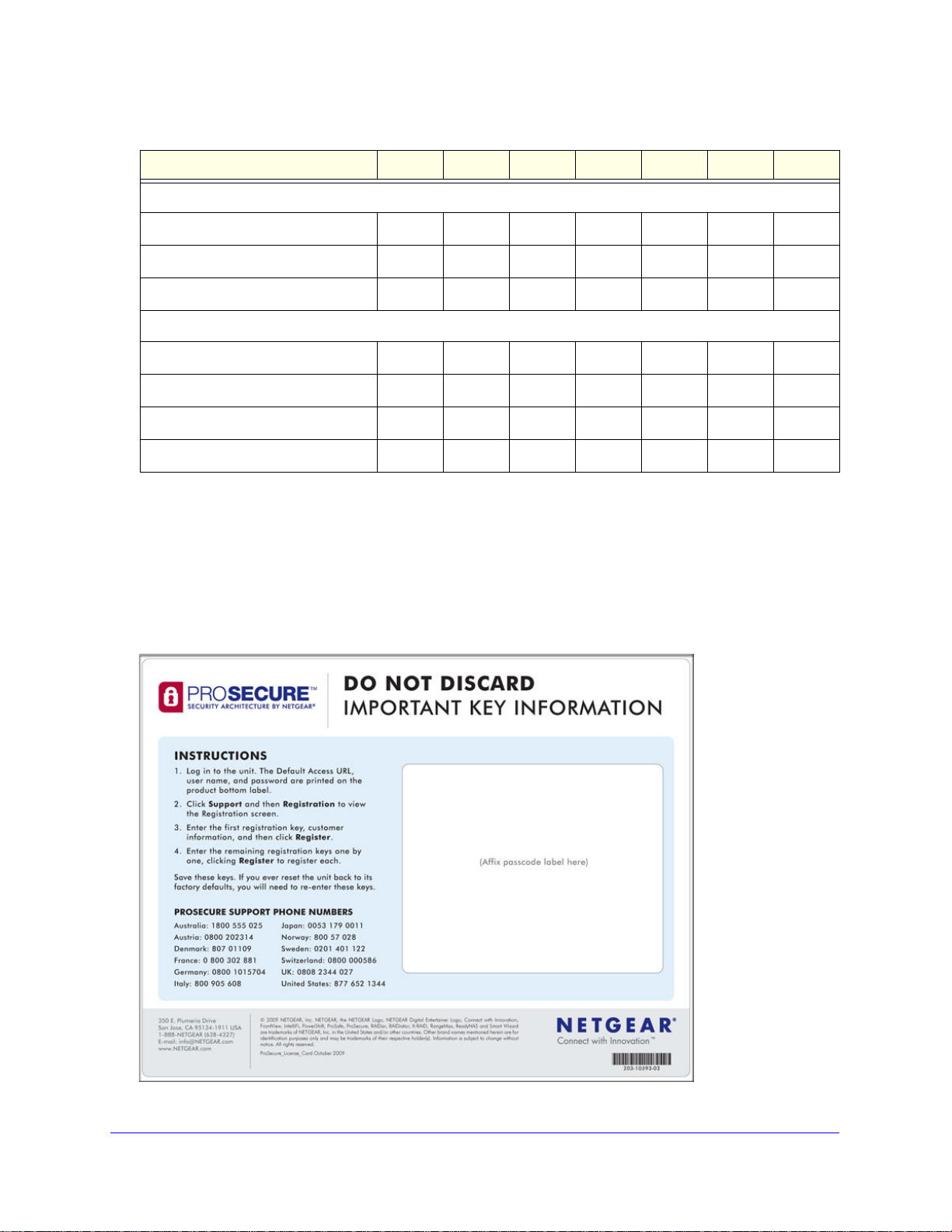
Service Registration Card with License Keys
Be sure to store the license key card that came with your UTM (see a sample card in the
following figure) in a secure location. If you do not use electronic licensing (see Electronic
Licensing on page 67), you need these service license keys to activate your product during
the initial setup. The service license keys are assigned to the serial number of your product.
Figure 1.
Introduction
23
Page 24

ProSecure Unified Threat Management (UTM) Appliance
Note: When you reset the UTM to the original factory default settings after
you have entered the license keys to activate the UTM (se e Register
the UTM with NETGEAR on page 65), the license keys are erased.
The license keys and the different types of licenses that are
available for the UTM are no longer displayed on the Registration
screen. However, af ter you have reconfigured the UTM to connect to
the Internet and to the NETGEAR registration server, the UTM
retrieves and restores all registration information based on its MAC
address and hardware serial number . You do not need to reenter the
license keys and reactivate the UTM.
Package Contents
The UTM product package contains the following items:
• ProSecure Unified Threat Management (UTM) Appliance
• One AC power cable
• Rubber feet (4)
• One rack-mounting kit (depends on UTM model)
• ProSecure Unified Threat Management UTM Installation Guide
• resource CD, including:
- Application Notes and other helpful information
- ProSafe VPN Client software (VPN01L) (depends on the UTM model)
• Service Registration Card with license keys
If any of the parts are incorrect, missing, or damaged, contact your NETGEAR dealer. Keep
the carton, including the original packing materials, in case you need to return the product for
repair.
Hardware Features
• Front Panel UTM5 and UTM10
• Front Panel UTM25
• Front Panel UTM50
• Front Panel UTM150
• Front Panel UTM9S and UTM25S and Network Modules
• LED Descriptions, UTM5, UTM10, UTM25, UTM50, and UTM150
• LED Descriptions, UTM9S, UTM25S, and their Network Modules
• Rear Panel UTM5, UTM10, and UTM25
Introduction
24
Page 25
ProSecure Unified Threat Management (UTM) Appliance
Power LED
Test LED
Left LAN LEDs
Right LAN LEDs
DMZ LED
Left WAN LED
Right WAN LED
USB port
• Rear Panel UTM50 and UTM150
• Rear Panel UTM9S and UTM25S
• Bottom Panels with Product Labels
The front panels contain ports an d LEDs; the rear panels contain port s, connectors, and other
components; and the bottom panels contain product labels.
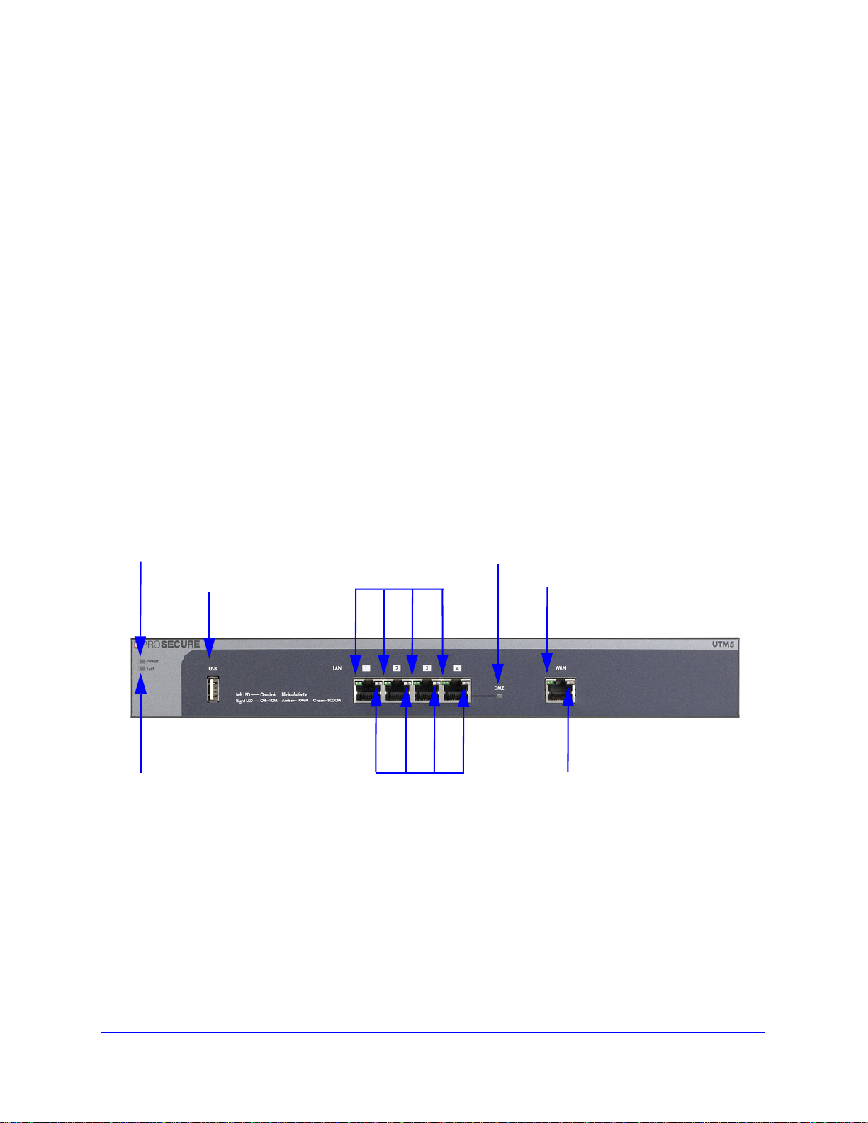
Front Panel UTM5 and UTM10
Viewed from left to right, the UTM5 and UTM10 front panel contains the following ports:
• One nonfunctioning USB port. This port is included for future management
enhancements. The port is currently not operable on the UTM.
• LAN Ethernet ports. Four switched N-way automatic speed negotiating, Auto MDI/MDIX,
Gigabit Ethernet ports with RJ-45 connectors.
• WAN Ethernet port. One independent N-way automatic speed negotiating, Auto
MDI/MDIX, Gigabit Ethernet ports with RJ-45 connectors.
The front panel also contains three groups of status indicator light-emitting diodes (LEDs),
including Power and Test LEDs, LAN LEDs, and WAN LEDs, all of which are explained in
detail in Table 2 on page 30. In addition, the front panel provides some LED explanation to
the left of the LAN ports.
Figure 2. Front panel UTM5 and UTM10
Introduction
25
Page 26
ProSecure Unified Threat Management (UTM) Appliance
Power LED
Test LED
Left LAN LEDs
Right LAN LEDs
DMZ LED
Left WAN LEDs
Right WAN LEDs
Active
WAN
USB port
LEDs
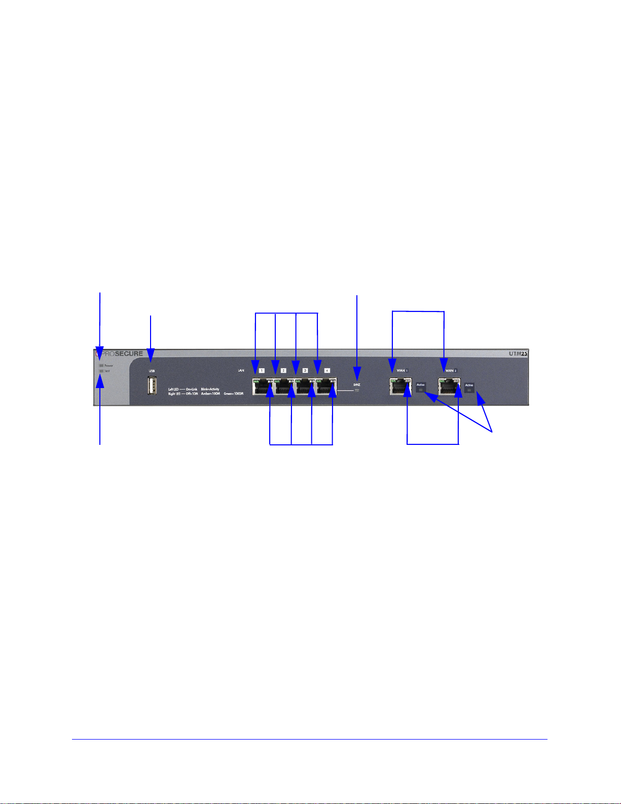
Front Panel UTM25
Viewed from left to right, the UTM25 front panel contains the following ports:
• One nonfunctioning USB port. This port is included for future management
enhancements. The port is currently not operable on the UTM.
• LAN Ethernet ports. Four switched N-way automatic speed negotiating, Auto MDI/MDIX,
Gigabit Ethernet ports with RJ-45 connectors.
• WAN Ethernet ports. Two independent N-way automatic speed negotiating, Auto
MDI/MDIX, Gigabit Ethernet ports with RJ-45 connectors.
The front panel also contains three groups of st atus indicator LEDs, including Powe r and Test
LEDs, LAN LEDs, and WAN LEDs, all of which are explained in detail in Table 2 on page 30.
In addition, the front panel provides some LED explanation to the left of the LAN ports.
Figure 3. Front panel UTM25
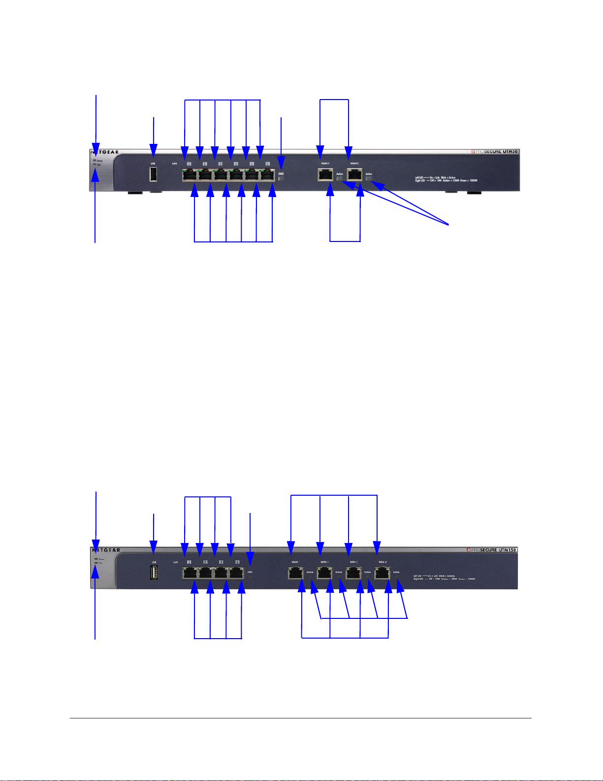
Front Panel UTM50
Viewed from left to right, the UTM50 front panel contains the following ports:
• One nonfunctioning USB port. This port is included for future management
enhancements. The port is currently not operable on the UTM.
• LAN Ethernet ports. Six switched N-way automatic speed negotiating, Auto MDI/MDIX,
Gigabit Ethernet ports with RJ-45 connectors.
• WAN Ethernet ports. Two independent N-way automatic speed negotiating, Auto
MDI/MDIX, Gigabit Ethernet ports with RJ-45 connectors.
The front panel also contains three groups of st atus indicator LEDs, including Powe r and Test
LEDs, LAN LEDs, and WAN LEDs, all of which are explained in detail in Table 2 on page 30.
In addition, the front panel provides some LED explanation to the right of the WAN ports.
Introduction
26
Page 27
ProSecure Unified Threat Management (UTM) Appliance
Power LED
Test LED
Left LAN LEDs
Right LAN LEDs
DMZ LED
Left WAN LEDs
Right WAN LEDs
Active
WAN
USB port
LEDs
Power LED
Test LED
Left LAN LEDs
Right LAN LEDs
DMZ LED
Left WAN LEDs
Right WAN LEDs
Active WAN LEDs
USB port
Figure 4. Front panel UTM50
Front Panel UTM150
Viewed from left to right, the UTM150 front panel contains the following ports:
• One nonfunctioning USB port. This port is included for future management
enhancements. The port is currently not operable on the UTM.
• LAN Ethernet ports. Four switched N-way automatic speed negotiating, Auto MDI/MDIX,
Gigabit Ethernet ports with RJ-45 connectors.
• WAN Ethernet ports. Four independent N-way automatic speed negotiating, Auto
MDI/MDIX, Gigabit Ethernet ports with RJ-45 connectors.
The front panel also contains three group s of status indicator LEDs, including Power and Test
LEDs, LAN LEDs, and WAN LEDs, all of which are explained in d et a il in Table 2 on page 30.
In addition, the front panel provides some LED explanation to the right of the WAN ports.
Figure 5. Front panel UTM150
Introduction
27
Page 28
ProSecure Unified Threat Management (UTM) Appliance
Power LED
Test LED
Left LAN LEDs
Right LAN LEDs
DMZ LED
Left WAN LEDs
Right WAN LEDs
Active WAN LEDs
USB port
USB LED
Slot 1
Slot 2
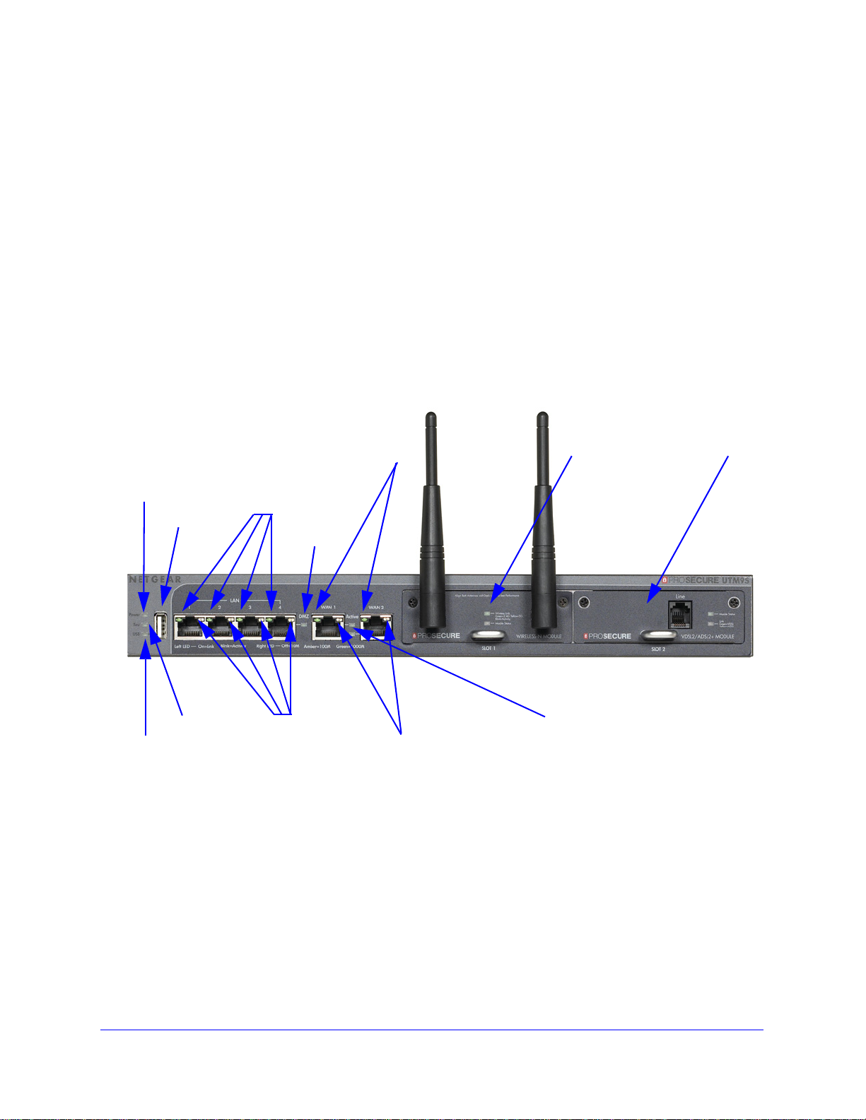
Front Panel UTM9S and UTM25S and Network Modules
Viewed from left to right, the UTM9S and UTM25S front panel contains the following ports
and slots:
• One USB port that can accept a 3G/4G dongle for wireless connectivity to an ISP. The
port is currently operable on the UTM9S and UTM25S only.
• LAN Ethernet ports. Four switched N-way automatic speed negotiating, Auto MDI/MDIX,
Gigabit Ethernet ports with RJ-45 connectors.
• WAN Ethernet ports. Two independent N-way automatic speed negotiating, Auto
MDI/MDIX, Gigabit Ethernet ports with RJ-45 connectors.
The front panel also contains three groups of st atus indicator LEDs, including Powe r and Test
LEDs, LAN LEDs, and WAN LEDs, all of which are explained in detail in Table 3 on page 32.
Some LED explanation is provided on the front panel below the LAN and WAN ports.
Figure 6. Front panel UTM9S and UTM25S
Introduction
28
Page 29
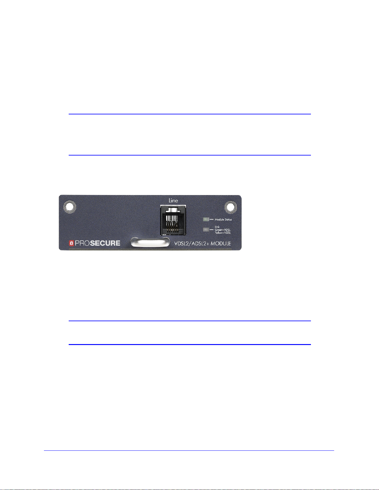
ProSecure Unified Threat Management (UTM) Appliance
xDSL Network Modules
The following xDSL network modules are available for insertion in one of the UTM9S or
UTM25S slots:
• NMSDSLA. VDSL/ADSL2+ network module, Annex A.
• NMSDSLB. VDSL/ADSL2+ network module, Annex B.
Note: In previous releases for the UTM9S, these network modules were
referred to as the UTM9SDSLA and UTM9SDSLB. The UTM9SDSLA
is identical to the NMSDSLA, and the UTM9SDSLB is identical to the
NMSDSLB.
The xDSL network module provides one RJ-11 port for connection to a telephone line. The
two LEDs are explained in Table 3 on page 32.
Figure 7. xDSL network module
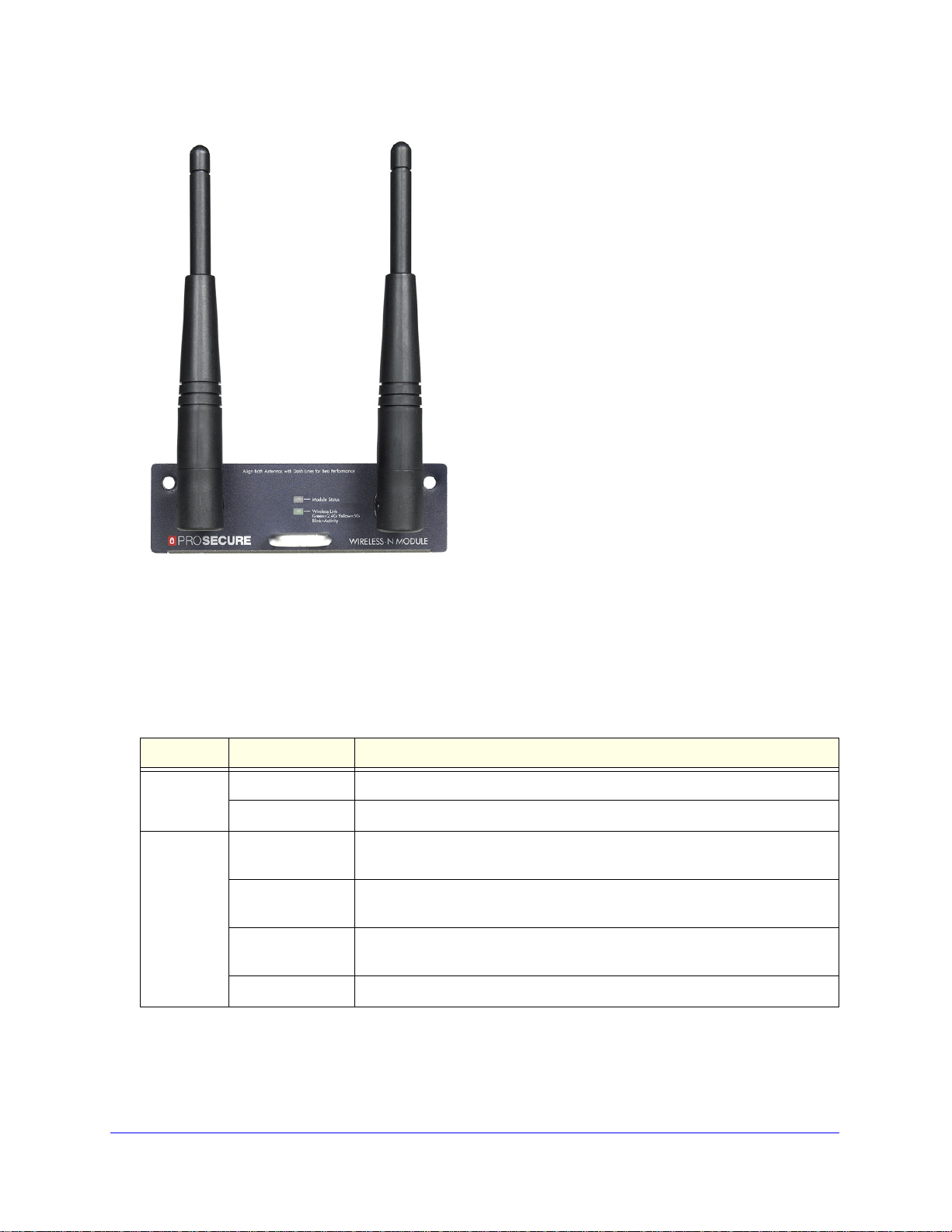
Wireless Network Modules
The wireless network module (NMSWLSN) can be inserted in one of the UTM9S and
UTM25S slots. The wireless network module does not provide any ports. The antennas are
detachable. The two LEDs are explained in Table 3 on page 32.
Note: In previous releases for the UTM9S, this network module was referred to
as the UTM9SWLSN. The UTM9SWLSN is identical to the NMSWLSN.
Introduction
29
Page 30
ProSecure Unified Threat Management (UTM) Appliance
Figure 8. Wireless network module
LED Descriptions, UTM5, UTM10, UTM25, UTM50, and UTM150
The following table describes the function of each LED.
Table 2. LED descriptions UTM5, UTM10, UTM25, UTM50, and UTM150
LED Activity Description
Power LED On (green) Power is supplied to the UTM.
Off Power is not supplied to the UTM.
Test LED On (amber) during
startup
On (amber) during
any other time
Blinking (amber) The UTM is writing to flash memory (during upgrading or resetting to
Off The UTM has booted successfully.
Test mode. The UTM is initializing. After approximately 2 minutes, when the
UTM has completed its initialization, the Test LED goes off.
The initialization has failed, or a hardware failure has occurred.
defaults).
Introduction
30
Page 31

ProSecure Unified Threat Management (UTM) Appliance
Table 2. LED descriptions UTM5, UTM10, UTM25, UTM50, and UTM150 (continued)
LED Activity Description
LAN ports
Left LED Off The LAN port has no link.
On (green) The LAN port has detected a link with a connected Ethernet device.
Blinking (green) Data is transmitted or received by the LAN port.
Right LED Off The LAN port is operating at 10 Mbps.
On (amber) The LAN port is operating at 100 Mbps.
On (green) The LAN port is operating at 1000 Mbps.
DMZ LED Off Port 4 (UTM5, UTM9S, UTM10, UTM25, and UTM150) or port 6 (UTM50) is
operating as a normal LAN port.
On (green) Port 4 (UTM5, UTM9S, UTM10, UTM25, and UTM150) or port 6 (UTM50) is
operating as a dedicated hardware DMZ port.
WAN ports
Left LED Off The WAN port has no physical link, that is, no Ethernet cable is plugged into
the UTM.
On (green) The WAN port has a valid connection with a device that provides an Internet
connection.
Blinking (green) Data is transmitted or received by the WAN port.
Right LED Off The WAN port is operating at 10 Mbps.
On (amber) The WAN port is operating at 100 Mbps.
On (green) The WAN port is operating at 1000 Mbps.
Active LED
(multiple
WAN port
models only)
Off The WAN port either is not enabled or has no link to the Internet.
On (green) The WAN port has a valid Internet connection.
Introduction
31
Page 32

ProSecure Unified Threat Management (UTM) Appliance
LED Descriptions, UTM9S, UTM25S, and their Network Modules
The following table describes the function of each LED on the UTM9S and UTM25S and their
network modules.
Table 3. LED descriptions UTM9S and UTM25S
LED Activity Description
Power LED On (green) Power is supplied to the UTM.
Off Power is not supplied to the UTM.
Test LED On (amber) during
startup
On (amber) during
any other time
Blinking (amber) The UTM is writing to flash memory (during upgrading or resetting to
Off The UTM has booted successfully.
USB LED On (green) A USB device is connected to the USB port.
Off A USB device is not connected to the USB port.
LAN ports
Left LED Off The LAN port has no link.
On (green) The LAN port has detected a link with a connected Ethernet device.
Blinking (green) Data is transmitted or received by the LAN port.
Right LED Off The LAN port is operating at 10 Mbps.
On (amber) The LAN port is operating at 100 Mbps.
On (green) The LAN port is operating at 1000 Mbps.
Test mode. The UTM is initializing. After approximately 2 minutes, when the
UTM has completed its initialization, the Test LED goes off.
The initialization has failed, or a hardware failure has occurred.
defaults).
DMZ LED Off Port 4 is operating as a normal LAN port.
On (green) Port 4 is operating as a dedicated hardware DMZ port.
WAN ports
Left LED Off The WAN port has no physical link, that is, no Ethernet cable is plugged into
the UTM.
On (green) The WAN port has a valid connection with a device that provides an Internet
connection.
Blinking (green) Data is transmitted or received by the WAN port.
Introduction
32
Page 33

ProSecure Unified Threat Management (UTM) Appliance
Security lock
receptacle
Console port
Factory Defaults
AC power
receptacle
reset button
Table 3. LED descriptions UTM9S and UTM25S (continued)
LED Activity Description
Right LED Off The WAN port is operating at 10 Mbps.
On (amber) The WAN port is operating at 100 Mbps.
On (green) The WAN port is operating at 1000 Mbps.
Active LED Off The WAN port either is not enabled or has no link to the Internet.
On (green) The WAN port has a valid Internet connection.
Wireless network module
Module
Status LED
Wireless
Link LED
xDSL network modules
Module
Status LED
Link LED Off The xDSL port has no Internet connection.
Off The module is not enabled.
On (green) The module is enabled.
Off The wireless access point is not enabled.
On (green) The wireless access point is enabled in 2.4-GHz operating mode.
Blinking (green) There is wireless activity in 2.4-GHz operating mode.
On (yellow) The wireless access point is enabled in 5-GHz operating mode.
Blinking (yellow) There is wireless activity in 5-GHz operating mode.
Off The module is enabled or has a link to the telephone line.
On (green) The module either is not enabled or has no link to the telephone line.
On (green) The xDSL port functions in ADSL mode.
On (yellow) The xDSL port functions in VDSL mode.
Rear Panel UTM5, UTM10, and UTM25
The rear panel of the UTM5, UTM10, and UTM25 includes the cable lock receptacle, the
console port, the Factory Defaults reset button, and the AC power connection.
Figure 9. Rear panel of the UTM5, UTM10, and UTM25
Introduction
33
Page 34

ProSecure Unified Threat Management (UTM) Appliance
Security lock
receptacle
Console port
Factory Defaults
AC power
receptacle
reset button
Viewed from left to right, the rear panel of the UTM5, UTM10, and UTM25 contains the
following components:
1. Cable security lock receptacle.
2. Console port. Port for connecting to an optional console terminal. The port has a DB9 male
connector. The default baud rate is 9600 K. The pinouts are (2) Tx, (3) Rx, (5) and (7) Gnd.
3. Factory Defaults Reset button. Using a sharp object, press and hold this button for about
8 seconds until the front panel Test LED flashes to reset the UTM to factory d efault settings.
Configuration changes are lost, and the default password is restored.
4. AC power receptacle. Universal AC input (100–240 VAC, 50–60 Hz).
Rear Panel UTM50 and UTM150
The rear panel of the UTM50 and UTM150 includes the cable lock receptacle, the console
port, the Factory Defaults reset button, and the AC power connection.
Figure 10. Rear panel of the UTM50 and UTM150
Viewed from left to right, the rear panel of the UTM50 and UTM150 contains the following
components:
1. Console port. Port for connecting to an optional console terminal. The port has a DB9
male connector. The default baud rate is 9600 K. The pinouts are (2) Tx, (3) Rx, (5) and
(7) Gnd.
2. Factory Defaults reset button. Using a sharp object, press and hold this button for about
8 seconds until the front panel Test LED flashes to reset the UTM to factory d efault settings.
Configuration changes are lost, and the default password is restored.
3. Cable security lock receptacle.
4. AC power receptacle. Universal AC input (100–240 VAC, 50–60 Hz).
Introduction
34
Page 35

ProSecure Unified Threat Management (UTM) Appliance
Security lock
receptacle
Console port
Factory Defaults
AC power
receptacle
reset button
Console switch
Power
switch
Rear Panel UTM9S and UTM25S
The rear panel of the UTM9S and UTM25S includes the cable lock receptacle, the console
port and console switch, the Factory Defaults reset button, the AC power connection, and the
power switch.
Figure 11. Rear panel of the UTM9S and UTM25S
Viewed from left to right, the rear panel of the UTM9S and UTM25S contains the following
components:
1. Cable security lock receptacle.
2. Factory Defaults Reset button. Using a sharp object, press and hold this button for about
8 seconds until the front panel Test LED flashes to reset the UTM to factory default settings.
Configuration changes are lost, and the default password is restored.
3. Console switch to select the console connection: Main Board (left position), Slot 1 (middle
position), or Slot 2 (right position).
4. Console port (9600,N,8,1). Port for connecting to an optional console terminal . The port has
a DB9 male connector. The default baud rate is 9600 K. The pinouts are (2) Tx, (3) Rx, (5)
and (7) Gnd.
5. AC power receptacle. Universal AC input (100–240 VAC, 50–60 Hz).
6. Power On/Off switch.
Introduction
35
Page 36
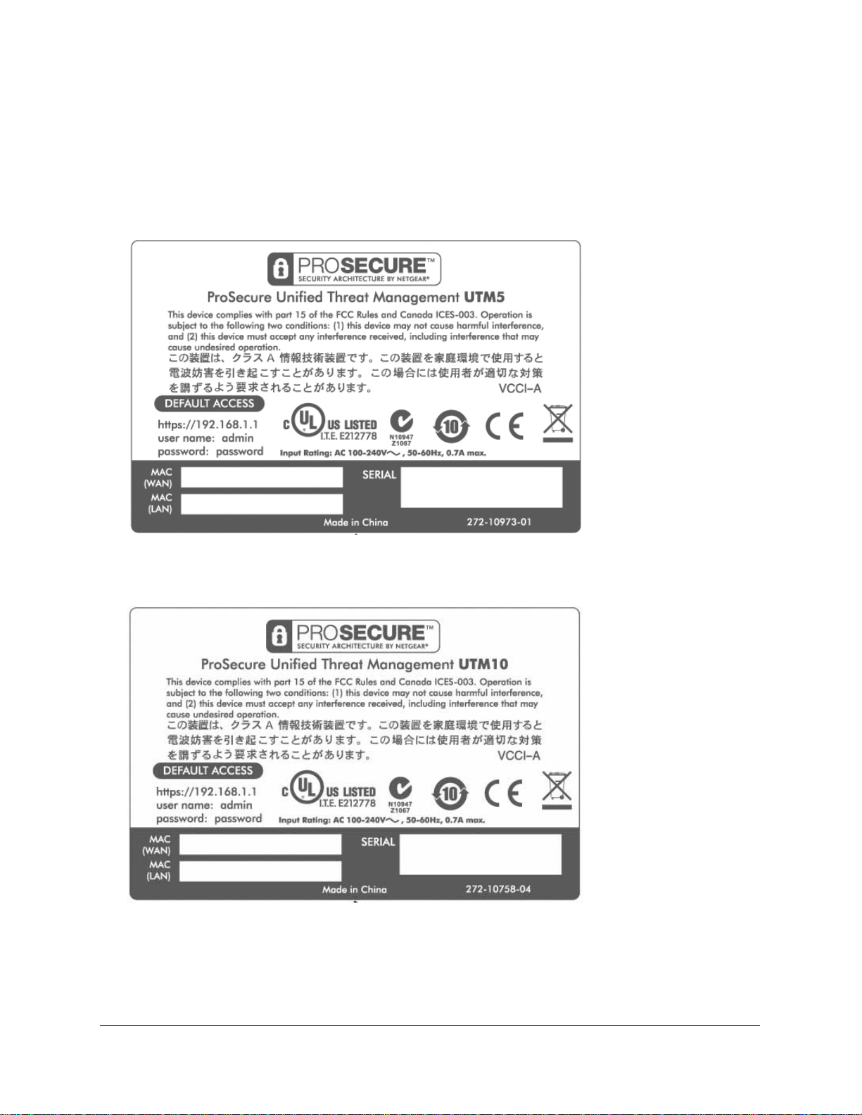
ProSecure Unified Threat Management (UTM) Appliance
Bottom Panels with Product Labels
The product label on the bottom of the UTM’s enclosure displays factory defaults settings,
regulatory compliance, and other information.
The following figure shows the product label for the UTM5:
Figure 12.
The following figure shows the product label for the UTM10:
Figure 13.
Introduction
36
Page 37

ProSecure Unified Threat Management (UTM) Appliance
The following figure shows the product label for the UTM25:
Figure 14.
The following figure shows the product label for the UTM50:
Figure 15.
Introduction
37
Page 38

ProSecure Unified Threat Management (UTM) Appliance
The following figure shows the product label for the UTM150:
Figure 16.
The following figure shows the product label for the UTM9S:
Figure 17.
Introduction
38
Page 39

ProSecure Unified Threat Management (UTM) Appliance
The following figure shows the product label for the UTM25S:
Figure 18.
Choose a Location for the UTM
The UTM is suitable for use in an office environment where it can be freestanding (on its
runner feet) or mounted into a standard 19-inch equipment rack. Alternatively, you can
rack-mount the UTM in a wiring closet or equipment room. A rack-mounting kit, containing
two mounting brackets and four screws, is provided in th e p ackage for the multiple WAN port
models.
Consider the following when deciding where to position the UTM:
• The unit is accessible, and cables can be connected easily.
• Cabling is away from sources of electrical noise. These include lift shafts, microwave
ovens, and air-conditioning units.
• Water or moisture cannot enter the case of the unit.
• Airflow around the unit and through the vents in the side of the case is not restricted.
Provide a minimum of 25-mm or 1-inch clearance.
• The air is as free of dust as possible.
• Temperature operating limits are not likely to be exceeded. Install the unit in a clean,
air-conditioned environment. For information about the recommended operating
temperatures for the UTM, see Appendix H, Default Settings and Technical
Specifications.
Note: For the UTM9S and UTM25S, see also Wireless Equipment
Placement and Range Guidelines on page 579.
Introduction
39
Page 40

ProSecure Unified Threat Management (UTM) Appliance
Use the Rack-Mounting Kit
Use the mounting kit for the UTM to install the appliance in a rack. (A mounting kit is provided
in the package for the multiple WAN port models.) Attach the mounting brackets using the
hardware that is supplied with the mounting kit.
Figure 19.
Before mounting the UTM in a rack, verify that:
• You have the correct screws (supplied with the installation kit).
• The rack onto which you will mount the UTM is suitably located.
Introduction
40
Page 41

2. Use the Setup Wizard to Provision the
UTM in Your Network
This chapter explains how to log in to the UTM and use the web management interface, how to
use the Setup Wizard to provision the UTM in your network, and how to register the UTM with
NETGEAR. The chapter contains the following sections:
• Steps for Initial Connection
• Log In to the UTM
• Web Management Interface Menu Layout
• Use the Setup Wizard to Perform the Initial Configuration
• Register the UTM with NETGEAR
• Verify Correct Installation
• What to Do Next
2
Steps for Initial Connection
• Qualified Web Browsers
• Requirements for Entering IP Addresses
Typically, the UTM is installed as a network gateway to function as a combined LAN switch,
firewall, and content scan engine to protect the network from all incoming and outgoing
malware threats.
Generally, five steps are required to complete the basic and security configuration of your
UTM:
1. Connect the UTM physically to your network. Connect the cables and restart your
network according to the instructions in the Installation Guide. See the ProSecure
Unified Threat Management UTM Installation Guide for complete steps. A PDF of the
Installation Guide is on the NETGEAR website at
http://www.prosecure.netgear.com/resources/document-library.php.
2. Log in to the UTM. After logging in, you are ready to set up and configure your UTM. See
Log In to the UTM on page 42.
3. Use the Setup Wizard to configure basic connections and s ecurity. During this phase,
you connect the UTM to one or more ISPs (more than one ISP applies to multiple WAN port
models only). See Use the Setup Wizard to Perform the Initial Configuration on page 47.
41
Page 42

ProSecure Unified Threat Management (UTM) Appliance
4. Verify the installation. See Verify Correct Installation on page 68.
5. Register the UTM. See Register the UTM with NETGEAR on page 65.
Each of these tasks is described separately in this chapter. The configuration of the WAN
mode (required for multiple WAN port models), Dynamic DNS, and other WAN options is
described in Chapter 3, Manually Configure Internet and WAN Settings.
The configuration of LAN, firewall, scanning, VPN, management, and monitoring features is
described in later chapters.
Qualified Web Browsers
To configure the UTM, you need to use a web browser such as Microsoft Internet Explorer 6
or later, Mo zilla Firefox 3 or later, or Apple Safari 3 or later with JavaScript, cookies, and SSL
enabled.
Although these web browsers are qualified for use with the UTM’s web management
interface, SSL VPN users should choose a browser that supports JavaScript, Java, cookies,
SSL, and ActiveX to take advantage of the full suite of applications. Java is required only for
the SSL VPN portal, not for the web management interface.
Requirements for Entering IP Addresses
The fourth octet of an IP address needs to be between 1 and 254 (both inclusive). This
requirement applies to any IP address that you enter on a screen of the web management
interface.
Log In to the UTM
To connect to the UTM, your computer needs to be configured to obtain an IP address
automatically from the UTM through DHCP.
To connect and log in to the UTM:
1. Start any of the qualified web browsers, as explained in the previous section, Qualified
Web Browsers.
2. In the address field, enter https://192.168.1.1. The NETGEAR Configuration Manager Login
screen displays in the browser. (The following figure shows the screen for the UTM50.) This
screen also provides the User Portal Login Link. For general information about the User
Portal Login Link, see Access the New SSL VPN Portal on page 353; for platform-specific
information, see Login Portals on page 380.
Note: The UTM factory default IP address is 192.168.1.1. If you change
the IP address, you need to use the IP address that you assigned to
the UTM to log in to the UTM.
Use the Setup Wizard to Provision the UTM in Y our Network
42
Page 43

ProSecure Unified Threat Management (UTM) Appliance
Figure 20.
3. In the User Name field, type admin. Use lowercase letters.
4. In the Password / Passcode field, type password. Here, too, use lowercase letters.
Note: The UTM user name and password are not the same as any user
name or password you might use to log in to your Internet
connection.
5. Click Login. The web management interface displays, showing the System Status screen.
The following figure shows the top part of the UTM50 System Status screen. For more
information, see View the System Status on page48 6.
Note: After 5 minutes of inactivity (the default login time-out), you are
automatically logged out.
Use the Setup Wizard to Provision the UTM in Y our Network
43
Page 44

ProSecure Unified Threat Management (UTM) Appliance
Figure 21.
Web Management Interface Menu Layout
The following figure shows the menu at the top the UTM50 web management interface as an
example.
Use the Setup Wizard to Provision the UTM in Y our Network
44
Page 45
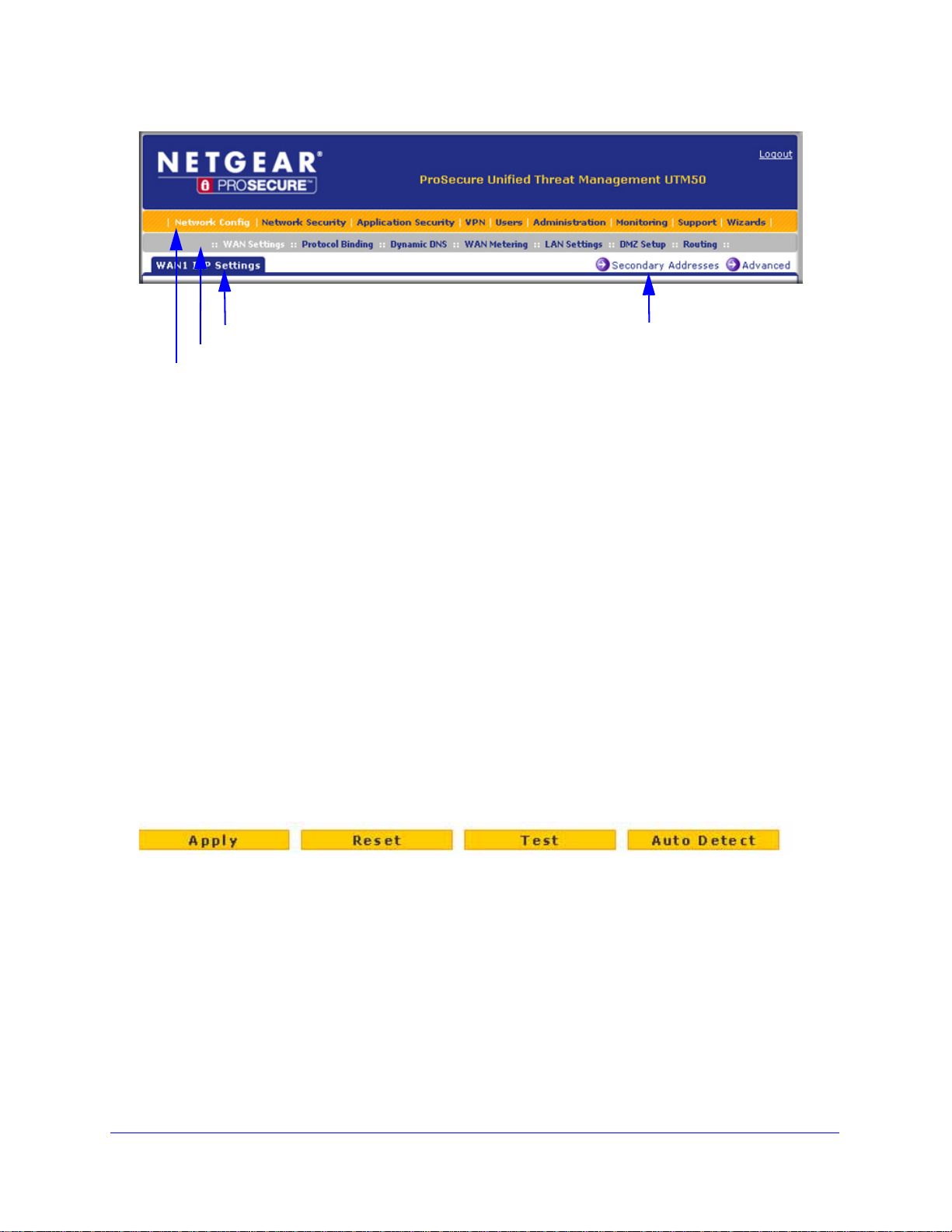
ProSecure Unified Threat Management (UTM) Appliance
1st level: Main navigation menu link (orange)
2nd level: Configuration menu link (gray)
3rd level: Submenu tab (blue)
Option arrow: Additional screen for submenu item
Figure 22.
The web management interface menu consists of the following components:
• 1st level: Main navigation menu links. The main navigation menu in the orange bar
across the top of the web management interface provides access to all the configuration
functions of the UTM, and remains constant. When you select a main navigation menu
link, the letters are displayed in white against an orange background.
• 2nd level: Configuration menu links. The configuration menu links in the gray bar
(immediately below the main navigation menu bar) change according to the main
navigation menu link that you select. When you select a configuration menu link, the
letters are displayed in white against a gray background.
• 3rd level: Submenu tabs. Each config uration menu item has one or more submenu tabs
that are listed below the gray menu bar. When you select a submenu tab, the text is
displayed in white against a blue background.
• Option arrows. If there are additional screens for the submenu item, links to the screens
display on the right side in blue letters against a white background, preceded by a white
arrow in a blue circle.
The bottom of each screen provides action buttons. The nature of the screen determines
which action buttons are shown. The following figure shows an example:
Figure 23.
Any of the following action buttons might display on screen (this list might not be complete):
• Apply. Save and apply the configuration.
• Reset. Cancel the changes and reset the configuration to the current values.
• Test. Test the configuration before you decide whether to save and apply the
configuration.
• Auto Detect. Enable the UTM to detect the configuration automatically and suggest
values for the configuration.
• Next. Go to the next screen (for wizards).
Use the Setup Wizard to Provision the UTM in Y our Network
45
Page 46

ProSecure Unified Threat Management (UTM) Appliance
• Back. Go to the previous screen (for wizards).
• Search. Perform a search operation.
• Cancel. Cancel the operation.
• Send Now. Send a file or report.
When a screen includes a table, table buttons display to let you configure the table entries.
The nature of the screen determines which table buttons are shown. The following figure
shows an example:
Figure 24.
Any of the following table buttons might display on screen:
• Select All. Select all entries in the table.
• Delete. Delete the selected entry or entries from the table.
• Enable. Enable the selected entry or entries in the table.
• Disable. Disable the selected entry or entries in the table.
• Add. Add an entry to the table.
• Edit. Edit the selected entry.
• Up. Move up the selected entry in the table.
• Down. Move down the selected entry in the table.
• Apply. Apply the selected entry.
Almost all screens and sections of screens have an accompanying help screen. To open the
help screen, click the (question mark) icon.
Use the Setup Wizard to Provision the UTM in Y our Network
46
Page 47

ProSecure Unified Threat Management (UTM) Appliance
Use the Setup Wizard to Perform the Initial Configuration
• Setup Wizard Step 1 of 10: LAN Settings
• Setup Wizard Step 2 of 10: WAN Settings
• Setup Wizard Step 3 of 10: System Date and Time
• Setup Wizard Step 4 of 10: Services
• Setup Wizard Step 5 of 10: Email Security
• Setup Wizard Step 6 of 10: Web Security
• Setup Wizard Step 7 of 10: Web Categories to Be Blocked
• Setup Wizard Step 8 of 10: Email Notification
• Setup Wizard Step 9 of 10: Signatures & Engine
• Setup Wizard Step 10 of 10: Saving the Configuration
The Setup Wizard facilitates the initial configuration of the UTM by taking you through 10
screens, the last of which allows you to save the configuration. If you prefer to perform the
initial WAN setup manually, see Chapter 3, Manually Configure Internet and WAN Settings.
To start the Setup Wizard:
1. Select Wizards from the main navigation menu. The Welcome to the Netgear
Configuration Wizard screen displays:
Figure 25.
2. Select the Setup Wizard radio button.
3. Click Next. The first Setup Wizard screen displays.
The following sections explain the 9 configuration screens of the Setup Wizard. On the 10th
screen, you can save your configuration.
The tables in the following sections explain the buttons and fields of the Setup Wizard
screens. Additional information about the settings in the Setup Wizard screens is provided in
other chapters that explain manual configuration; each of the following sections provides a
specific link to a section in another chapter.
Use the Setup Wizard to Provision the UTM in Y our Network
47
Page 48

ProSecure Unified Threat Management (UTM) Appliance
Setup Wizard Step 1 of 10: LAN Settings
Figure 26.
Enter the settings as explained in the following table, and then click Next to go the following
screen.
Note: In this first step, you are configuring the LAN settings for the UTM’s
default VLAN. For more information about VLANs, see Manage
Virtual LANs and DHCP Options on page 98.
Use the Setup Wizard to Provision the UTM in Y our Network
48
Page 49

ProSecure Unified Threat Management (UTM) Appliance
Table 4. Setup Wizard Step 1: LAN Settings screen settings
Setting Description
LAN TCP/IP Setup
IP Address Enter the IP address of the UTM’s default VLAN (the factory default address is
192.168.1.1).
Note: Always make sure that the LAN port IP address and DMZ port IP address are in
different subnets.
Note: If you change the LAN IP address of the UTM’s default VLAN while being
connected through the browser, you are disconnected. You then need to open a new
connection to the new IP address and log in again. For example, if you change the
default IP address from 192.168.1.1 to 10.0.0.1, you now need to enter https://10.0.0.1
in your browser to reconnect to the web management interface.
Subnet Mask Enter the IP subnet mask. The subnet mask specifies the network number portion of an
IP address. The UTM automatically calculates the subnet mask based on the IP
address that you assign. Unless you are implementing subnetting, use 255.255.255.0
as the subnet mask (computed by the UTM).
DHCP
Disable DHCP Server If another device on your network is the DHCP server for the default VLAN, or if you will
configure the network settin gs o f al l of your computers manually, select the Disable
DHCP Server radio button to disable the DHCP server. By default, this radio button is
not selected, and the DHCP server is enabled.
Enable DHCP Server Select the Enable DHCP Server radio button to enable the UTM to function as a
Dynamic Host Configuration Protocol (DHCP) server, providing TCP/IP configuration
for all computers connected to the default VLAN. Enter the following settings.
Domain Name This setting is optional. Enter the domain name of the UTM.
Starting IP
Address
Ending IP
Address
Enter the starting IP address. This address specifies the first of the
contiguous addresses in the IP address pool. Any new DHCP client
joining the LAN is assigned an IP address between this address and
the ending IP address. The IP address 192.168.1.2 is the default
starting address.
Enter the ending IP address. This address specifies the last of the
contiguous addresses in the IP address pool. Any new DHCP client
joining the LAN is assigned an IP address between the starting IP
address and this IP address. The IP address 192.168.1.100 is the
default ending address.
Note: The starting and ending DHCP IP addresses should be in the
same network as the LAN TCP/IP address of the UTM (that is, the IP
address in the LAN TCP/IP Setup section as described earlier in this
table).
Use the Setup Wizard to Provision the UTM in Y our Network
49
Page 50

ProSecure Unified Threat Management (UTM) Appliance
Table 4. Setup Wizard Step 1: LAN Settings screen settings (continued)
Setting Description
Enable DHCP Server
(continued)
DHCP Relay Select the DHCP Relay radio button to use the UTM as a DHCP relay agent for a
Enable LDAP
information
Primary DNS
Server
Secondary DNS
Server
WINS Server This setting is optional. Enter a WINS server IP address to specify
Lease Time Enter a lease time. This specifies the duration for which IP addresses
DHCP server somewhere else on your network. Enter the following setting:
Relay Gateway The IP address of the DHCP server for which the UTM serves as a
Select the Enable LDAP information check box to enable the DHCP server to provide
Lightweight Directory Access Protocol (LDAP) server information. Enter the following
settings.
Note: The LDAP settings that you specify as part of the VLAN profile are used only for
SSL VPN and UTM authentication, but not for web and email security.
LDAP Server The IP address or name of the LDAP server.
This setting is optional. If an IP address is specified, the UTM
provides this address as the primary DNS server IP address. If no
address is specified, the UTM provides its own LAN IP address as
the primary DNS server IP address.
This setting is optional. If an IP address is specified, the UTM
provides this address as the secondary DNS server IP address.
the Windows NetBIOS server, if one is present in your network.
are leased to clients.
relay.
Search Base The search objects that specify the location in the directory tree from
which the LDAP search begins. You can specify multiple search
objects, separated by commas. The search objects include:
• CN (for common name)
• OU (for organizational unit)
• O (for organization)
• C (for country)
• DC (for domain)
For example, to search the Netgear.net domain for all last names of
Johnson, you would enter:
cn=Johnson,dc=Netgear,dc=net
Port The port number for the LDAP server. The default setting is 0 (zero).
DNS Proxy
Enable DNS Proxy This setting is optional. Select the Enable DNS Proxy radio button to enable the UTM
to provide a LAN IP address for DNS address name resolution. This radio button is
selected by default.
Note: When the DNS Proxy option is disabled, all DHCP clients receive the DNS IP
addresses of the ISP but without the DNS proxy IP address.
Use the Setup Wizard to Provision the UTM in Y our Network
50
Page 51

ProSecure Unified Threat Management (UTM) Appliance
Table 4. Setup Wizard Step 1: LAN Settings screen settings (continued)
Setting Description
Inter VLAN Routing
Enable Inter VLAN
Routing
This setting is optional. To ensure that traffic is routed only to VLANs for which
inter-VLAN routing is enabled, select the Enable Inter VLAN Routing check box. This
setting is disabled by default. When the Enable Inter VLAN Routing check box is not
selected, traffic from this VLAN is not routed to other VLANs, and traffic from other
VLANs is not routed to this VLAN.
Note: For information about inter-VLAN firewall rules, see VLAN Rules on page 154.
After you have completed the steps in the Setup Wizard, you can ch ange the LAN settings by
selecting Network Config > LAN Settings > Edit LAN Profile. For more information about
these LAN settings, see VLAN DHCP Options on page 101.
Setup Wizard Step 2 of 10: WAN Settings
Figure 27.
Use the Setup Wizard to Provision the UTM in Y our Network
51
Page 52

ProSecure Unified Threat Management (UTM) Appliance
Enter the settings as explained in the following table, and then click Next to go the following
screen.
Note: Instead of manually entering the settings, you can also click the
Auto Detect action button at the bottom of the screen. The
autodetect process probes the WAN port for a range of connection
methods and suggests one that your ISP is most likely to support.
Table 5. Setup Wizard Step 2: WAN Settings screen settings
Setting Description
ISP Login
Does your Internet
connection require a
login?
ISP Ty pe
What type of ISP
connection do you
use?
Austria (PPTP) If your ISP is Austria Telecom or any other ISP that uses PPTP for login, select this
If you need to enter login information every time you connect to the Internet through
your ISP, select the Yes radio button. Otherwise, select the No radio button, which is
the default setting, and skip the ISP Type section. If you select the Yes radio button,
enter the following settings.
Login The login name that your ISP has assigned to you.
Password The password that your ISP has assigned to you.
If your connection is PPPoE or PPTP, then you need to log in. Select the Yes radio
button. Based on the connection that you select, the text fields that require data entry
are highlighted. If your ISP has not assigned any login information, then select the No
radio button and skip this section. If you select the Yes radio button, enter the following
settings.
radio button and enter the following settings:
Account Name The account name is also known as the host name or system
name. Enter the valid account name for the PPTP connection
(usually your email ID assigned by your ISP). Some ISPs
require you to enter your full email address here.
Domain Name Your domain name or workgroup name assigned by your ISP,
or your ISP’s domain name. You can leave this field blank.
Idle Timeout Select the Keep Connected radio button to keep the
connection always on. To log out after the connection is idle
for a period:
1. Select the Idle Timeout radio button.
2. In the time-out field, enter the number of minutes to wait
before disconnecting.
This is useful if your ISP charges you based on the period that
you are logged in.
Use the Setup Wizard to Provision the UTM in Y our Network
52
Page 53

ProSecure Unified Threat Management (UTM) Appliance
Table 5. Setup Wizard Step 2: WAN Settings screen settings (continued)
Setting Description
Austria (PPTP)
(continued)
Other (PPPoE) If you have installed login software such as WinPoET or Ethernet, then your connection
My IP Address The IP address assigned by the ISP to make the connection
with the ISP server.
Server IP Address The IP address of the PPTP server.
type is PPPoE. Select this radio button and enter the following settings:
Account Name The valid account name for the PPPoE connection.
Domain Name The name of your ISP’s domain or your domain name if your
ISP has assigned one. You can leave this field blank.
Idle Timeout Select the Keep Connected radio button to keep the
connection always on. To log out after the connection is idle
for a period:
1. Select the Idle Timeout radio button.
2. In the time-out field, enter the number of minutes to wait
before disconnecting.
This is useful if your ISP charges you based on the period that
you are logged in.
Note: When you use a PPPoE connection and select the Idle
Timeout radio button, you cannot configure load balancing
(see Configure Load Balancing (Multiple WAN Port Models)
on page 86). To use load balancing on a PPPoE connection,
select the Keep Connected radio button.
Connection Reset Select the Connection Reset check box to specify a time
when the PPPoE WAN connection is reset, that is, the
connection is disconnected momentarily and then
reestablished. Then, specify the disconnect time and delay.
Disconnect Time Specify the hour and minutes when the connection should be
disconnected.
Delay Specify the period in seconds after which the connection
should be reestablished.
Internet (IP) Address
Click the Current IP Address link to see the currently assigned IP address.
Get Dynamically from
ISP
If your ISP has not assigned you a static IP address, select the Get dynamically from
ISP radio button. The ISP automatically assigns an IP address to the UTM using DHCP
network protocol.
Client Identifier Select the Client Identifier check box if your ISP requires the
client identifier information to assign an IP address using
DHCP.
Vendor Class Identifier Select the Vendor Class Identifier check box if your ISP
requires the vendor class identifier information to assign an IP
address using DHCP.
Use the Setup Wizard to Provision the UTM in Y our Network
53
Page 54

ProSecure Unified Threat Management (UTM) Appliance
Table 5. Setup Wizard Step 2: WAN Settings screen settings (continued)
Setting Description
Use Static IP Address If your ISP has assigned you a fixed (static or permanent) IP address, select the Use
Static IP Address radio button and enter the following settings.
IP Address The static IP address assigned to you. This address identifies
the UTM to your ISP.
Subnet Mask The subnet mask, which is usually provided by your ISP.
Gateway IP Address The IP address of the ISP’s gateway, which is usually
provided by your ISP.
Domain Name Server (DNS) Servers
Get Automatically from
ISP
Use These DNS
Servers
If your ISP has not assigned any Domain Name Servers (DNS) addresses, select the
Get Automatically from ISP radio button.
If your ISP has assigned DNS addresses to you, select the Use These DNS Servers
radio button. Make sure that you fill in valid DNS server IP addresses in the fields.
Incorrect DNS entries might cause connectivity issues.
Primary DNS Server The IP address of the primary DNS server.
Secondary DNS Serve The IP address of the secondary DNS server.
After you have completed the steps in the Set up Wizard, you can change to the W AN settings
by selecting Network Config > WAN Settings. Then click the Edit button in the Action
column of the WAN interface for which you want to change the settings.
For more information about these WAN settings, see Manually Configure the Internet
Connection on page 75.
Setup Wizard Step 3 of 10: System Date and Time
Figure 28.
Use the Setup Wizard to Provision the UTM in Y our Network
54
Page 55

ProSecure Unified Threat Management (UTM) Appliance
Enter the settings as explained in the following table, and then click Next to go the following
screen.
Table 6. Setup Wizard Step 3: System Date and Time screen settings
Setting Description
Set Time, Date, and NTP Servers
Date/Time From the drop-down list, select the local time zone in which the UTM operates. The
correct time zone is required in order for scheduling to work correctly. The UTM
includes a real-time clock (RTC), which it uses for scheduling.
Automatically Adjust for
Daylight Savings Time
NTP Server (default or
custom)
If daylight savings time is supported in your region, select the Automatically Adjust
for Daylight Savings Time check box.
From the drop-down list, select an NTP server:
• Use Default NTP Servers. The UTM’s RTC is updated regularly by contacting a
default NETGEAR NTP server on the Internet.
• Use Custom NTP Servers. The UTM’s RTC is updated regularly by contacting
one of the two NTP servers (primary and backup), both of which you need to
specify in the fields that become available with this selection.
Note: If you select this option but leave either the Server 1 or Server 2 field blank, both
fields are set to the default NETGEAR NTP servers.
Note: A list of public NTP servers is available at
http://support.ntp.org/bin/view/Servers/WebHome.
Server 1 Name / IP
Address
Server 2 Name / IP
Address
Enter the IP address or host name of the primary NTP server.
Enter the IP address or host name of the backup NTP server.
After you have completed the steps in the Setup Wizard, you can change the date and time
by selecting Administration > System Date & Time. For more information about these
settings, see Configure Date and Time Service on page 456.
Setup Wizard Step 4 of 10: Services
Figure 29.
Use the Setup Wizard to Provision the UTM in Y our Network
55
Page 56

ProSecure Unified Threat Management (UTM) Appliance
IMPORTANT:
Enter the settings as explained in the following table, and then click Next to go the following
screen.
Table 7. Setup Wizard Step 4: Services screen settings
Setting Description
Email
SMTP SMTP scanning is enabled by
default on standard service port 25.
POP3 POP3 scanning is enabled by default
on standard service port 110.
IMAP IMAP scanning is enabled by default
on standard service port 143.
Web
To disable any of these services, clear the
corresponding check box. You can change the
standard service port or add another port in the
corresponding Ports to Scan field.
HTTP HTTP scanning is enabled by default
on standard service port 80.
HTTPS HT TPS scann ing is disabled by
default.
FTP FTP scanning is enabled by default
on standard service port 21.
To disable HTTP scanning, clear the corresponding
check box. You can change the standard service port
or add another port in the corresponding Ports to Scan
field.
To enable HTTPS scanning, select the corresponding
check box. You can change the standard service port
(443) or add another port in the corresponding Ports to
Scan field.
To disable FTP scanning, clear the corresponding
check box. You cannot change the standard service
port in the corresponding Ports to Scan field.
To enable scanning of encrypted emails, you need to configure the
SSL settings (see Configure HTTPS Scanning and SSL Certificates
on page 228).
After you have completed the steps in the Setup Wizard, you can change the security
services by selecting Application Security > Services. For more information about these
settings, see Customize Email Protocol Scan Settings on page 194 and Customize Web
Protocol Scan Settings on page 210.
Use the Setup Wizard to Provision the UTM in Y our Network
56
Page 57

ProSecure Unified Threat Management (UTM) Appliance
Setup Wizard Step 5 of 10: Email Security
Figure 30.
Enter the settings as explained in the following table, and then click Next to go the following
screen.
Table 8. Setup Wizard Step 5: Email Security screen settings
Setting Description
Action
SMTP From the SMTP drop-down list, select one of the following actions to be
taken when an infected email is detected:
• Block infected email. This is the default setting. The email is
blocked, and a log entry is created.
• Delete attachment. The email is not blocked, but the attachment
is deleted, and a log entry is created.
• Log only. Only a log entry is created. The email is not blocked,
and the attachment is not deleted.
• Quarantine attachment. The email is not blocked, but the
attachment is quarantined on a ReadyNAS, and a log entry is
created (see the Note on page 193).
• Quarantine infected email. The email is quarantin ed on a
ReadyNAS, and a log entry is created (see the Note on page 193).
POP3 From the POP3 drop-down list, select one of the following actions to be
taken when an infected email is detected:
• Delete attachment. This is the default setting. The email is n ot
blocked, but the attachment is deleted, and a log entry is created.
• Log only. Only a log entry is created. The email is not blocked,
and the attachment is not deleted.
• Quarantine attachment. The email is not blocked, but the
attachment is quarantined on a ReadyNAS, and a log entry is
created (see the Note on page 193).
To disable antivirus
scanning, clear the
corresponding check
box.
Use the Setup Wizard to Provision the UTM in Y our Network
57
Page 58

ProSecure Unified Threat Management (UTM) Appliance
Table 8. Setup Wizard Step 5: Email Security screen settings (continued)
Setting Description
IMAP From the IMAP drop-down list, select one of the following actions to be
taken when an infected email is detected:
• Delete attachment. This is the default setting. The email is not
blocked, but the attachment is deleted, and a log entry is created.
• Log only. Only a log entry is created. The email is not blocked,
and the attachment is not deleted.
• Quarantine attachment. The email is not blocked, but the
attachment is quarantined on a ReadyNAS, and a log entry is
created (see the Note on page 193).
Scan Exceptions
The default maximum size of the file or message that is scanned is 2048 KB, but you can define a maximum size
of up to 10240 KB. However, setting the maximum size to a high value might affect the UTM’s performance (see
Performance Management on page 428).
From the drop-down list, select one of the following actions to be taken when the file or message exceeds the
maximum size:
• Skip. The file is not scanned but skipped, leaving the end user vulnerable. This is the default setting.
• Block. The file is blocked and does not reach the end user.
To disable antivirus
scanning, clear the
corresponding check
box.
After you have completed the steps in the Setup Wizard, you can change the email security
settings by selecting Application Security > Email Anti-Virus. The Email Anti-Virus screen
also lets you specify notification settings and email alert settings. For more information about
these settings, see Customize Email Antivirus and Notification Settings on page 196.
Setup Wizard Step 6 of 10: Web Security
Figure 31.
Enter the settings as explained in the following table, and then click Next to go the following
screen.
Use the Setup Wizard to Provision the UTM in Y our Network
58
Page 59

ProSecure Unified Threat Management (UTM) Appliance
Table 9. Setup Wizard Step 6: Web Security screen settings
Setting Description
Action
HTTP From the HTTP drop-down list, select one of the following actions to be
taken when an infected web file or object is detected:
• Delete file. This is the default setting. The web file or obj ect is
deleted, and a log entry is created.
• Log only. Only a log entry is created. The web file or object is not
deleted.
• Quarantine file. The web file or object is quarantined, and a log
entry is created (see the Note on page 193).
Select the Streaming check box to enable streaming of partially
downloaded and scanned HTTP file parts to the user. This method
allows the user to experience more transparent web downloading.
Streaming is enabled by default.
HTTPS From the HTTPS drop-down list, select one of the following actions to
be taken when an infected web file or object is detected:
• Delete file. This is the default setting. The web file or obj ect is
deleted, and a log entry is created.
• Log only. Only a log entry is created. The web file or object is not
deleted.
• Quarantine file. The web file or object is quarantined, and a log
entry is created (see the Note on page 193).
Select the Streaming check box to enable streaming of partially
downloaded and scanned HTTPS file parts to the user. This method
allows the user to experience more transparent web downloading.
Streaming is enabled by default.
To disable antivirus
scanning, clear the
corresponding check
box.
FTP From the FTP drop-down list, select one of the following actions to be
taken when an infected web file or object is detected:
• Delete file. This is the default setting. The FTP file or object is
deleted, and a log entry is created.
• Log only. Only a log entry is created. The FTP file or object is not
deleted.
• Quarantine file. The FTP file or object is quarantined, and a log
entry is created (see the Note on page 193).
Scan Exceptions
The default maximum size of the file or obj ect that is scanned is 2048 KB, but you can define a maximum size of
up to 10240 KB. However, setting the maximum size to a high value might affect the UTM’s performance (see
Performance Management on page 428).
From the drop-down list, select one of the following actions to be taken when the file or message exceeds the
maximum size:
• Skip. The file is not scanned but skipped, leaving the end user vu lnerable. This is the default setting.
• Block. The file is blocked and does reach the end user.
After you have completed the steps in the Setup Wizard, you can change the web security
settings by selecting Application Security > HTTP/HTTPS > Malware Scan. The Malware
Use the Setup Wizard to Provision the UTM in Y our Network
59
Page 60

ProSecure Unified Threat Management (UTM) Appliance
Scan screen also lets you specify HTML scanning and notification settings. For more
information about these settings, see Configure Web Malware or Antivirus Scans on
page 216.
Setup Wizard Step 7 of 10: Web Categories to Be Blocked
Figure 32.
Use the Setup Wizard to Provision the UTM in Y our Network
60
Page 61

ProSecure Unified Threat Management (UTM) Appliance
Enter the settings as explained in the following table, and then click Next to go the following
screen.
Table 10. Setup Wizard Step 7: Web Categories to be blocked screen settings
Setting Description
Blocked Web Categories
Select the Enable Blocking check box to enable blocking of web categories. (By default, this check box is
selected.)
Select the check boxes of any web categories that you want to block. Use the action buttons at the top of the
section in the following way:
• Allow All. All web categories are allowed.
• Block All. All web categories are blo cked.
• Set to Defaults. Blocking and allowing of web categories are returned to their default settings. See
Table 41 on page 193 for information about the web categories that are blocked by default. Categories that
are preceded by a green square are allowed by default; categories that ar e preceded by a pink square are
blocked by default.
Blocked Categories Scheduled Days
Make one of the following selections:
• Select the All Days radio button to enable content filterin g to be active all days of the week.
• Select the Specific Days radio button to enable content filte ring to be acti ve on th e days tha t are speci fied
by the check boxes.
Blocked Categories Time of Day
Make one of the following selections:
• Select the All Day radio button to enable content filteri ng to be active all 24 hours of each selected day.
• Select the Specific Times radio button to enable content filtering to be a ctive during the time that is
specified by the Start Time and End Time fields for each day that content filtering is a ctive.
After you have completed the steps in th e Setup Wizard, you can change th e content-filtering
settings by selecting Application Security > HTTP/HTTPS > Content Filtering. The
Content Filtering screen lets you specify additional filtering tasks and notification se ttings. For
more information about these settings, see Configure Web Content Filtering on p ag e 218.
Use the Setup Wizard to Provision the UTM in Y our Network
61
Page 62

ProSecure Unified Threat Management (UTM) Appliance
Setup Wizard Step 8 of 10: Email Notification
Figure 33.
Enter the settings as explained in the following table, and then click Next to go the following
screen.
Table 11. Setup Wizard Step 8: Email Notification screen settings
Setting Description
Administrator Email Notification Settings
Show as mail sender A descriptive name of the sender for email identification purposes. For example,
enter UTM_Notifications@netgear.com.
SMTP server The IP address and port number or Internet name and port number of your ISP’s
outgoing email SMTP server. The default port number is 25.
Note: If you leave this field blank, the UTM cannot send email notifications.
This server requires
authentication
Send notifications to The email address to which the notifications should be sent. Typically, this is the
If the SMTP server requires authentication, select the This server requires
authentication check box, and enter the user name and password.
User name The user name for SMTP server authentication.
Password The password for SMTP server authentication.
email address of the administrator.
After you have completed the steps in the Setup Wizard, you can change the administrator
email notification settings by selecting Network Config > Email Notification. For more
information about these settings, see Configure the Email Notification Server on page 466.
Use the Setup Wizard to Provision the UTM in Y our Network
62
Page 63

ProSecure Unified Threat Management (UTM) Appliance
Setup Wizard Step 9 of 10: Signatures & Engine
Figure 34.
Enter the settings as explained in the following table, and then click Next to go the following
screen.
Table 12. Setup Wizard Step 9: Signatures & Engine screen settings
Setting Description
Update Settings
Update From the drop-down list, select one of the following options:
• Never. The pattern and firmware files are never automatically updated.
• Scan engine and Signatures. The pattern and firmware files are
automatically updated according to the settings in the Update Frequency
section onscreen (see explanations later in this table).
Update From Set the update source server by selecting one of the following radio buttons:
• Default update server. Files are updated from the default NETGEAR update
server.
• Server address. Files are updated from the server that you specify. Enter the
IP address or host name of the update server in the Server address field.
Use the Setup Wizard to Provision the UTM in Y our Network
63
Page 64

ProSecure Unified Threat Management (UTM) Appliance
Table 12. Setup Wizard Step 9: Signatures & Engine screen settings (continued)
Setting Description
Update Frequency
Specify the frequency with which the UTM checks for file updates:
• Weekly. From the drop-down lists, select the weekday, hour, and minutes that the updates occur.
• Daily. From the drop-down lists, select the hour and minutes that the updates occur.
• Every. From the drop-down list, select the frequency with which the updates occur. The range is from 15
minutes to 12 hours.
HTTPS Proxy Settings
Enable If computers on the network connect to the Internet through a proxy server, select
the Enable check box to specify and enable a proxy server. Enter the following
settings.
Proxy server The IP address and port number of the proxy server.
User name The user name for proxy server authentication.
Password The password for proxy server authentication.
After you have completed the steps in the Setup Wizard , you can cha nge the signatures and
engine settings by selecting Administration > System Update > Signatures & Engine. For
more information about these settings, see Update the Scan Signatures and Scan Engine
Firmware on page 454.
Setup Wizard Step 10 of 10: Saving the Configuration
Figure 35.
Click Apply to save your settings and automatically restart the system.
Use the Setup Wizard to Provision the UTM in Y our Network
64
Page 65

ProSecure Unified Threat Management (UTM) Appliance
IMPORTANT:
WARNING:
Register the UTM with NETGEAR
• Use the Web Management Interface to Activate Licenses
• Electronic Licensing
• Automatic Retrieval of Licenses after a Factory Default Reset
Use the Web Management Interface to Activate Licenses
To receive threat management component updates and technical support, you need to
register your UTM with NETGEAR. The UTM comes with four 30-day trial licenses:
• Web protection
• Email protection
• Support and maintenance
• Application control and IPS
The service license keys are provided with the product package (see Service Registration
Card with License Keys on page 23). For electronic licensing, you do not need the service
license keys (see Electronic Licensing on page 67).
Activating the service licenses initiates their terms of use. Activate
the licenses only when you are ready to start using this unit. If your
unit has never been registered before, you can use the 30-day trial
period for all four types of licenses to perform the initial testing and
configuration. To use the trial period, do not click Register in Step
of the following procedure, but click Trial instead.
If your UTM is connected to the Internet, you can activate the service licenses:
1. Select Support > Registration. The Registration screen displays (see Figure 36 on
page 66).
2. Enter the license key in the Registration Key field.
3. Fill out the customer and va lu e -a d de d r es e ll e r ( VAR) fields.
To activate the 30-day trial period for a license, do not click
Register but click Trial instead. For more information, see the
Important information at the beginning of this section.
Use the Setup Wizard to Provision the UTM in Y our Network
65
Page 66

ProSecure Unified Threat Management (UTM) Appliance
Note: If you have used the 30-day trial licenses, these trial licenses are
revoked once you activate the purchased service license keys. The
purchased service license keys offer 1 year or 3 years of service.
4. Click Register. The UTM activates the license and registers the unit with the registration and
update server.
5. Repeat Step 2 and Step 4 for additional license keys.
Figure 36.
Use the Setup Wizard to Provision the UTM in Y our Network
66
Page 67

ProSecure Unified Threat Management (UTM) Appliance
To change customer or VAR information after you have registered the UTM:
1. Make the changes on the Registration screen.
2. Click Update Info. The new data is saved by the registration and update server.
To retrieve and display the registered information:
Click Retrieve Info. The re g i s t e r e d d a ta is r e t r i e v e d f r o m t h e registration and update server.
Electronic Licensing
If you have purchased the UTM with a 1- or 3-year license, you can use the electronic
licensing option. When the UTM is connected to the Internet, you need to enter only your
customer information and optional value-added reseller (VAR) information on the Register
screen but do not need to enter the license numbers. When you click Register, the UTM
automatically downloads and activates the license keys because the serial number of the
UTM is linked to the license.
If you have purchased a license from a VAR (either directly or over the web) after purchase of
the UTM, the VAR should email you the license keys or provide them to you in another way.
To register and activate the license keys, follow the regular registration procedure that is
explained in the previous section.
Automatic Retrieval of Licenses after a Factory Default Reset
When you reset the UTM to the original factory default settings after you have entered the
license keys to activate the UTM, the license keys are erased. The license keys and the
different types of licenses that are available for the UTM are no longer displayed on the
Registration screen. However , after you have reco nfigured the UTM to connect to the Internet
and to the NETGEAR registration server, the UTM can retrieve and restore all registration
information based on its MAC address and hardware serial number. You do not need to
reenter the license keys and reactivate the UTM.
To let the UTM automatically retrieve and restore all registration information:
1. Select Support > Registration. The Registration screen displays (see Figure 36 on
page 66).
2. Click Retrieve Info.
Note: In the unlikely situation that you have been directed to use a
nondefault update server, you first need to enter the update server
address in the Server address field on the Signatures & Engine
screen and click Apply (see Update the Scan Signatures and Scan
Engine Firmware on page 454) before you can let the UTM
automatically retrieve and restore all registration information.
Use the Setup Wizard to Provision the UTM in Y our Network
67
Page 68

ProSecure Unified Threat Management (UTM) Appliance
Verify Correct Installation
• Test Connectivity
• Test HTTP Scanning
Test the UTM before deploying it in a live production environment. The following instructions
walk you through a couple of quick tests that are designed to ensure that your UTM is
functioning correctly.
Test Connectivity
Verify that network traffic can pass through the UTM:
1. Ping an Internet URL.
2. Ping the IP address of a device on either side of the UTM.
Test HTTP Scanning
Verify that the UTM scans HTTP traffic correctly:
1. Log in to the UTM web management interface, and then verify that HTTP scanning is
enabled. HTTP scanning is enabled by default (see Setup Wizard Step 4 of 10: Services
on page 55).
2. Take note of the web securit y settings for HTTP (see Setup Wizard Step 6 of 10: Web
Security on page 58).
3. If client computers have direct access to the Internet through your LAN, try to download the
eicar.com test file from http://www.eicar.org/download/eicar.com.
The eicar.com test file is a legitimate denial of service (DoS) attack and is safe to use
because it is not a malware threat and does not include any fragments of malware code.
The test file is provided by EICAR, an organization that unites efforts against computer
crime, fraud, and misuse of computers or networks.
4. Check the downloaded eicar.com test file, and note the attached malware information file.
What to Do Next
You have completed setting up the UTM to the network. The UTM is now ready to scan the
protocols and services that you specified and perform automatic updates based on the
update source and frequency that you specified.
If you need to change the settings, or to view reports or logs, log in to the UTM web
management interface, using the default IP address or the IP address that you assigned to
the UTM in Setup Wizard Step 1 of 10: LAN Settings on page 48.
Use the Setup Wizard to Provision the UTM in Y our Network
68
Page 69

ProSecure Unified Threat Management (UTM) Appliance
The UTM is ready for use. However, the following sections describe important tasks that you
might want to address before you deploy the UTM in your network:
• Configure the WAN Mode (required if you want to use multiple WAN ports)
• Configure Authentication Domains, Groups, and Users
• Manage Digital Certificates for VPN Connections
• Use the IPSec VPN Wizard for Client and Gateway Configurations
• Build a Portal Using the SSL VPN Wizard
Use the Setup Wizard to Provision the UTM in Y our Network
69
Page 70

3. Manually Configure Internet and WAN
Settings
This chapter contains the following sections:
• Internet and WAN Configuration Tasks
• Automatically Detecting and Connecting the Internet Connections
• Manually Configure the Internet Connection
• Configure the WAN Mode
• Configure Secondary WAN Addresses
• Configure Dynamic DNS
• Set the UTM’s MAC Address and Configure Advanced WAN Options
• Additional WAN-Related Configuration Tasks
Note: The initial Internet configuration of the UTM is described in
Chapter 2, Use the Setup Wizard to Provision the UTM in Your
Network. If you used the Setup Wizard to configure your Internet
settings, you need this chapter only to configure WAN features such
as multiple WAN connections (not applicable to the single WAN port
models) and dynamic DNS, and to configure secondary WAN
addresses and advanced WAN options.
3
Note: The Wireless Settings configuration menu is shown on the UTM9S
and UTM25S only, accessible under the Network Config main
navigation menu.
70
Page 71

ProSecure Unified Threat Management (UTM) Appliance
Internet and WAN Configuration Tasks
Note: For information about configuring the DSL interface of the UTM9S
and UTM25S, see Appendix A, xDSL Network Module for the
UTM9S and UTM25S. The information in this chapter also applies to
the WAN interfaces of the UTM9S and UTM25S.
Generally, five steps, three of which are optional, are required to complete the WAN Internet
connection of your UTM.
Complete these steps:
1. Configure the Internet connections to your ISPs. During this phase, you connect to
your ISPs. See Automatically Detecting and Connecting the Internet Connections on
page 71 or Manually Configure the Internet Connection on page 75.
2. Configure the WAN mode (required for multiple WAN port models). For all models,
select either NAT or classical routing. For the multiple WAN port models, select dedicated
(single WAN) mode, auto-rollover mode, or load balancing mode. For load balancing, you
can also select any necessary protocol bindings. See Configure the WAN Mode on page 80.
3. Configure secondary WAN addresses on the WAN ports (optional). Configure aliases
for each WAN port. See Configure Secondary WAN Addresses on page 89.
4. Configure Dynamic DNS on the WAN ports (optional). Configure your fully qualified
domain names during this phase (if necessary). See Configure Dynamic DNS on page 91.
5. Configure the WAN options (optional). Optionally, you can enable each WAN port to
respond to a ping, and you can change the factory default MTU size and port speed.
However, these are advanced features, and changing them is not usually required. See Set
the UTM’s MAC Address and Configure Advanced WAN Options on page 94.
Each of these tasks is detailed separately in this chapter.
Note: For information about how to configure the WAN meters, see Enable
the WAN Traffic Meter on page 462.
Automatically Detecting and Connecting the Internet Connections
To set up your UTM for secure Internet connections, the web management interface provides
the option to detect the network connections and configure the WAN port or ports
automatically. You can also configure the Internet connections and ports manually (see
Manually Configure the Internet Connection on page 75).
Manually Configure Internet and W AN Settings
71
Page 72

ProSecure Unified Threat Management (UTM) Appliance
To configure the WAN ports automatically for connection to the Internet:
1. Select Network Config > WAN Settings. The WAN screen displays. (The following
figure shows the UTM50.)
Figure 37.
The UTM5 and UTM10 screens show one WAN interface; the UTM25 and UTM50
screens show two WAN interfaces; the UTM150 screen shows four WAN interfaces; the
UTM9S and UTM25S screens show two WAN interfaces, a slot (SLOT-1 or SLOT-2) in
which a xDSL network module can be installed, and a USB port in which a 3G/4G dongle
can be installed.
The WAN Settings table displays the following fields:
• WAN. The WAN interface.
• Status. The status of the WAN interface (UP or DOWN).
• WAN IP. The IP address of the WAN interface.
• Failure Detection Method. The failure detection method that is active for the WAN
interface. The following methods can be displayed:
- None
- WAN DNS (WAN DNS servers)
- Custom DNS (the IP address of the configured DNS server is displayed)
- Ping (the configured IP address is displayed)
You can set the failure detection method for each WAN interface on its corresponding
WAN Advanced Options screen (see Configure Auto-Rollover Mode and the Failure
Detection Method (Multiple WAN Port Models) on page 82).
• Action. The Edit button provides access to the WAN ISP Settings screen (se e Step 2)
for the corresponding WAN interface; the Status button provides access to the
Connection Status screen (see Step 6) for the corresponding WAN interface.
2. Click the Edit button in the Action column of the WAN interface or slot for which you want to
configure the connection to the Internet automatically. The WAN ISP Settings screen
displays.
The following figure shows the WAN1 ISP Settings screen of the UTM50 as an example:
Manually Configure Internet and WAN Settings
72
Page 73

ProSecure Unified Threat Management (UTM) Appliance
Figure 38.
3. Click the Auto Detect button at the bottom of the screen. The autodetect process probes
the WAN port for a range of connection methods and suggests one that your ISP is most
likely to support.
The autodetect process returns one of the following results:
• If the autodetect process is successful, a status bar at the top of the screen displays
the results (for example, DHCP service detected).
• If the autodetect process senses a connection method that requires input from you, it
prompts you for the information. All methods with their required settings are e xplained
in the following table:
Manually Configure Internet and W AN Settings
73
Page 74

ProSecure Unified Threat Management (UTM) Appliance
Table 13. Internet connection methods
Connection method Manual data input required
DHCP (Dynamic IP) No data is required.
PPPoE Login, password, account name, and domain name.
PPTP Login, password, account name, your IP address, and the server IP address.
Fixed (Static) IP IP address, subnet mask, and gateway IP address, and related data supplied
by your ISP.
• If the autodetect process does not find a connection, you are prompted to check the
physical connection between your UTM and the cable or DSL modem, satellite dish,
or wireless ISP radio antenna, or to check your UTM’s MAC address. For more
information, see Set the UTM’s MAC Address and Configure Advanced WAN Options
on page 94 and Troubleshoot the ISP Connection on page 541.
4. Click Apply to save your changes.
5. Click Test to evaluate your entries. The UTM attempts to make a connection according to
the settings that you entered.
6. To verify the connection:
a. Return to the WAN screen by selecting Network Config > WAN Settings.
b. Click the Status button in the Action column for the WAN interface that you just
configured to display the Connection Status pop-up screen.
Figure 39.
Note: The Connection Status screen should show a valid IP address and
gateway. For more information about the Connection Status screen,
see View the WAN, xDSL, or USB Port Status on page 504.
Manually Configure Internet and WAN Settings
74
Page 75

ProSecure Unified Threat Management (UTM) Appliance
What to do next:
• If the automatic ISP configuration is successful:
You are connected to the Internet through the W AN interface that you just configured. For
the multiple WAN port models, continue with the configuration process for the other WAN
interfaces. If you are done with the configuration of WAN interfaces, continue with
Configure the WAN Mode on page 80.
• If the automatic ISP configuration fails:
You can attempt a manual configuration as described in Manually Configure the Internet
Connection on page 75 or you might need to change the MAC address as described in
Set the UTM’s MAC Address and Configure Advanced WAN Options on page 94. For
information about troubleshooting, see Troubleshoot the ISP Connection on page 541.
Manually Configure the Internet Connection
Unless your ISP automatically assigns your configuration through DHCP, you need to obtain
configuration parameters from your ISP to establish an Internet connection manually. The
necessary parameters for various connection types are listed in Table 13 on page 74.
To configure the WAN ISP settings for an interface manually:
1. Select Network Config > WAN Settings. The WAN screen displays (see Figure 37 on
page 72, which shows the UTM50).
2. Click the Edit button in the Action column of the WAN interface for which you want to
configure the connection to the Internet. The WAN ISP Settings screen displays (see
Figure 38 on page 73, which shows the WAN1 ISP Settings screen as an example).
3. Locate the ISP Login section onscreen:
Figure 40.
In the ISP Login section, select one of the following options:
• If your ISP requires an initial login to establish an Internet connection, select Yes.
(The default is No.)
• If a login is not required, select No, and ignore the Login and Password fields.
4. If you selected Yes, enter the login name in the Login field and the password in the
Password field. This information is provided by your ISP.
5. In the ISP Type section of the screen, select the type of ISP connection that you use from
the two listed options. By default, Other (PPPoE) is selected, as shown in the following
figure:
Manually Configure Internet and W AN Settings
75
Page 76

ProSecure Unified Threat Management (UTM) Appliance
Figure 41.
6. If your connection is PPTP or PPPoE, your ISP requires an initial login. Enter the settings as
explained in the following table:
Table 14. PPTP and PPPoE settings
Setting Description
Austria (PPTP) If your ISP is Austria Telecom or any other ISP that uses PPTP for login, select this radio
button, and enter the following settings:
Account Name The account name is also known as the host name or system name.
Enter the account name for the PPTP connection (usually your email ID
assigned by your ISP). Some ISPs require you to enter your full email
address here.
Domain Name Your domain name or workgroup name assigned by your ISP, or your
ISP’s domain name. You can leave this field blank.
Idle Timeout Select the Keep Connected radio button to keep the connection always
on. To log out after the connection is idle for a period:
1. Select the Idle Timeout radio button.
2. In the time-out field, enter the number of minutes to wait before
disconnecting.
This is useful if your ISP charges you based on the period that you are
logged in.
My IP Address The IP address assigned by the ISP to make the connection with the
ISP server.
Server IP
Address
The IP address of the PPTP server.
Manually Configure Internet and WAN Settings
76
Page 77

ProSecure Unified Threat Management (UTM) Appliance
Table 14. PPTP and PPPoE settings (continued)
Setting Description
Other (PPPoE) If you have installed login software, then your connection type is PPPoE. Select this radio
button, and enter the following settings:
Account Name The account name for the PPPoE connection.
Domain Name The name of your ISP’s domain or your domain name if your ISP has
you assigned one. You can leave this field blank.
Idle Timeout Select the Keep Connected radio button to keep the connection always
on. To log out after the connection is idle for a period:
1. Select the Idle Timeout radio button.
2. In the time-out field, enter the number of minutes to wait before
disconnecting.
This is useful if your ISP charges you based on the period that you are
logged in.
Note: When you use a PPPoE connection and select the Idle Timeout
radio button, you cannot configure load balancing (see Configure Load
Balancing (Multiple WAN Port Models) on page 86). To use load
balancing on a PPPoE connection, select the Keep Connected radio
button. When you have configured load balancing, the Idle Timeout
radio button and time-out field are masked out.
Connection
Reset
Select the Connection Reset check box to specify a time when the
PPPoE WAN connection is reset, that is, the connection is disconnected
momentarily and then reestablished. Then, specify the disconnect time
and delay.
Disconnect
Time
Delay Specify the period in seconds after which the connection
Specify the hour and minutes when the connection should
be disconnected.
should be reestablished.
7. In the Internet (IP) Address section of the screen (see the following figure), configure the IP
address settings as explained in the following table. Click the Current IP Address link to
see the currently assigned IP address.
Figure 42.
Manually Configure Internet and W AN Settings
77
Page 78

ProSecure Unified Threat Management (UTM) Appliance
Table 15. Internet IP address settings
Setting Description
Get Dynamically
from ISP
Use Static IP
Address
If your ISP has not assigned you a static IP address, select the Get Dynamically from
ISP radio button. The ISP automatically assigns an IP address to the UTM using DHCP
network protocol.
Client Identifier If your ISP requires the client identifier information to assign an
IP address using DHCP, select the Client Identifier check box.
Vendor Class Identifier If your ISP requires the vendor class identifier information to
assign an IP address using DHCP, select the Vendor Class
Identifier check box.
If your ISP has assigned you a fixed (static or permanent) IP address, select the Use
Static IP Address radio button, and enter the following settings:
IP Address Static IP address assigned to you. This address identifies the
UTM to your ISP.
Subnet Mask The subnet mask is usually provided by your ISP.
Gateway IP Address The IP address of the ISP’s gateway is usually provided by
your ISP.
8. In the Domain Name Server (DNS) Servers section of the screen (see the following figure),
specify the DNS settings as explained in the following table.
Figure 43.
Table 16. DNS server settings
Setting Description
Get Automatically
from ISP
Use These DNS
Servers
If your ISP has not assigned any Domain Name Server (DNS) addresses, select the
Get Automatically from ISP radio button.
If your ISP has assigned DNS addresses, select the Use These DNS Servers radio
button. Make sure that you fill in valid DNS server IP addresses in the fields. Incorrect
DNS entries might cause connectivity issues.
Primary DNS Server The IP address of the primary DNS server.
Secondary DNS Server The IP address of the secondary DNS server.
Manually Configure Internet and WAN Settings
78
Page 79

ProSecure Unified Threat Management (UTM) Appliance
9. Click Apply to save any changes to the WAN ISP settings. (Or click Reset to discard any
changes and revert to the previous settings.)
10. Click Test to evaluate your entries. The UTM attempts to make a connection according to
the settings that you entered.
11. To verify the connection:
a. Return to the WAN screen by selecting Network Config > WAN Settings.
b. Click the Status button in the Action column for the WAN interface that you just
configured to display the Connection Status pop-up screen.
Figure 44.
Note: The Connection Status screen should show a valid IP address and
gateway. For more information about the Connection Stat us screen,
see View the WAN, xDSL, or USB Port Status on page 504.
What to do next:
• If the manual ISP configuration is successful:
You are connected to the Internet through the W AN interface that you just configured. For
the multiple WAN port models, continue with the configuration process for the other WAN
interfaces. If you are done with the configuration of WAN interfaces, continue with
Configure the WAN Mode on page 80.
• If the manual ISP configuration fails:
Y ou might need to change the MAC address as de scribed in Set the UTM’s MAC Address
and Configure Advanced WAN Options on page 94. For information about
troubleshooting, see Troubleshoot the ISP Connection on page 541.
Manually Configure Internet and W AN Settings
79
Page 80

ProSecure Unified Threat Management (UTM) Appliance
Configure the WAN Mode
• Overview of the WAN Modes
• Configure Network Address Translation (All Models)
• Configure Classical Routing (All Models)
• Configure Auto-Rollover Mode and the Failure Detection Method (Multiple WAN Port
Models)
• Configure Load Balancing and Optional Protocol Binding (Multiple WAN Port Models)
Overview of the WAN Modes
For the multiple WAN port models, the UTM can be configured on a mutually exclusive basis
for either auto-rollover (for increased system reliability) or load balancing (for maximum
bandwidth efficiency). If you do not select load balancing, you need to specify one WAN
interface as the primary interface.
Note: For the UTM9S and UTM25S only, you can also use a DSL or USB
interface for load balancing mode, primary WAN mode, and
auto-rollover mode. However , in auto-rollover mode, a USB interface
can function only as a rollover interface.
For information about how to configure the DSL WAN interface, see
Appendix A, xDSL Network Module for the UTM9S and UTM25S.
For information about how to configure the USB W AN interface, see
Appendix C, 3G/4G Dongles for the UTM9S and UTM25S.
• Load balancing mode. The UTM distributes the outbound traffic equally among the
WAN interfaces that are functional. Depending on the UTM model, you can configure up
to four WAN interfaces. The UTM support s weighted load balancing and round-robin load
balancing (see Configure Load Balancing and Optional Protocol Binding (Multiple WAN
Port Models) on page 85).
Note: Scenarios could arise when load balancing needs to be bypassed
for certain traffic or applications. If cert ain traffic needs to travel on a
specific WAN interface, configure protocol binding rules for that
WAN interface. The rule should match the desired traffic.
• Primary WAN mode. The selected WAN interface is made the primary interface. The
other interfaces are disabled.
• Auto-rollover mode. A WAN interface is defined as the primary link, and another
interface needs to be defined as the rollover link. If the UTM model has more than two
Manually Configure Internet and WAN Settings
80
Page 81

ProSecure Unified Threat Management (UTM) Appliance
WARNING:
WAN interfaces, the remaining interfaces are disabled. As long as the primary link is up,
all traffic is sent over the primary link. When the primary link goes down, the rollover link
is brought up to send the traffic. When the primary link comes back up, traffic
automatically rolls back to the original primary link.
If you want to use a redundant ISP link for backup purposes, select the WAN interface
that needs to function as the primary link for this mode. Ensure that the backup WAN
interface has also been configured and that you configure the WAN failure detection
method on the WAN Advanced Options screen to support auto-rollover (see Configure
Auto-Rollover Mode and the Failure Detection Method (Multiple WAN Port Models) on
page 82).
Whichever WAN mode you select for the multiple WAN port models, you also need to select
either NAT or classical routing, as explained in the following sections.
Note: NAT and classical routing also apply to the single WAN port models.
When you change the W AN mode, the WAN interface or interfaces
restart. If you change from primary WAN mode to load balancing
mode, or the other way around, the interface through which you
can access the UTM might change. Take note of the IP addresses
of the interfaces before you change the WAN mode.
Configure Network Address Translation (All Models)
Network Address Translation (NAT) allows all computers on your LAN to share a single public
Internet IP address. From the Internet, there is only a single device (the UTM) and a single IP
address. Computers on your LAN can use any private IP address range, and these IP
addresses are not visible from the Internet.
Note the following about NAT:
• The UTM uses NA T to select the corre ct computer (on your LAN) to receive any incoming
data.
• If you have only a single public Internet IP address, you need to use NAT (the default
setting).
• If your ISP has provided you with multiple public IP addresses, you can use one address
as the primary shared address for Internet access by your computers, and you can map
incoming traffic on the other public IP addresses to specific computers on your LAN. This
one-to-one inbound mapping is configured using an inbound firewall rule.
Manually Configure Internet and W AN Settings
81
Page 82

ProSecure Unified Threat Management (UTM) Appliance
WARNING:
WARNING:
Changing the WAN mode from classical routing to NAT causes all
LAN WAN and DMZ WAN inbound rules to revert to default
settings.
To configure NAT:
1. Select Network Config > WAN Settings > WAN Mode. The WAN Mode screen
displays (see Figure 45 on page 83).
2. In the NAT (Network Address Translation) section of the screen, select the NAT radio button.
3. Click Apply to save your settings.
Configure Classical Routing (All Models)
In classical routing mode, the UTM performs routing, but without NAT. To gain Internet
access, each computer on your LAN needs to have a valid static Internet IP address.
If your ISP has allocated a number of static IP addresses to you, and yo u have assigned one
of these addresses to each computer, you can choose classical routing. Or, you can use
classical routing for routing private IP addresses within a campus environment.
To view the status of the WAN ports, you can view the Router Status screen (see View the
System Status on page 486).
Changing the WAN mode from NAT to classical routing causes all
LAN WAN and DMZ WAN inbound rules to revert to default
settings.
To configure classical routing:
1. Select Network Config > WAN Settings > WAN Mode. The WAN Mode screen
displays (see Figure 45 on page 83).
2. In the NAT (Network Address Translation) section of the screen, select the Classical
Routing radio button.
3. Click Apply to save your settings.
Configure Auto-Rollover Mode and the Failure Detection Method (Multiple WAN Port Models)
To use a redundant ISP link for backup purposes, ensure that the backup WAN interface has
already been configured. Then select the WAN interface that should function as the primary
link for this mode, and configure the W AN failu re detection method on the W AN Mode screen
to support auto-rollover.
Manually Configure Internet and WAN Settings
82
Page 83

ProSecure Unified Threat Management (UTM) Appliance
When the UTM is configured in auto-rollover mode, it uses the selected WAN failure
detection method to detect the status of the primary link connection at regular intervals. Link
failure is detected in one of the following ways:
• DNS queries sent to a DNS server
• Ping request sent to an IP address
• None (no failure detection is performed)
From the primary WAN interface, DNS queries or ping requests are sent to the specified IP
address. If replies are not received after a specified number of retries, the primary WAN
interface is considered down, and a rollover to the backup WAN interface occurs. When the
primary WAN interface comes back up, another rollover occurs from the backup WAN
interface back to the primary WAN interface. The WAN failure detection method that you
select applies only to the primary WAN interface, that is, it monitors the primary link only.
Configure Auto-Rollover Mode
To configure auto-rollover mode:
1. Select Network Config > WAN Settings > WAN Mode. The WAN Mode screen
displays:
Figure 45.
2. In the Load Balancing Settings section of the screen, configure the following settings:
a. Select the Primary WAN Mode radio button.
b. From the corresponding drop-down list on the right, select a WAN interface to
function as the primary WAN interface. The other WAN interface or interfaces
become disabled.
c. Select the Auto Rollover check box.
d. From the corresponding drop-down list on the right, select a WAN interface to
function as the backup WAN interface.
Manually Configure Internet and W AN Settings
83
Page 84

ProSecure Unified Threat Management (UTM) Appliance
Note: Ensure that the backup WAN int erface is configured bef ore enabling
auto-rollover mode.
3. Click Apply to save your settings.
Configure the Failure Detection Method
To configure the failure detection method:
1. Select Network Config > WAN Settings. The WAN screen displays (see Figure 37 on
page 72).
2. Click the Edit button in the Action column of the WAN interface that you selected as the
primary WAN interface. The WAN ISP Settings screen displays (see Figure 38 on page 73,
which shows the WAN1 ISP Settings screen as an example).
3. Click the Advanced option arrow at the upper right of the screen. The WAN Advanced
Options screen displays for the WAN interface that you selected. (For an image of the entire
screen, see Figure 53 on page 95.)
4. Locate the Failure Detection Method section onscreen (see the following figure). Enter the
settings as explained in the following table.
Figure 46.
Table 17. Failure detection method settings
Setting Description
WAN Failure Detection Method
Select a failure detection method from the drop-down list. DNS queries or pings are sent through the WAN
interface that is being monitored. The retry interval and number of failover attempts determine how quickly
the UTM switches from the primary link to the backup link in case the primary link fails, or when the primary
link comes back up, switches back from the backup link to the primary link.
WAN DNS DNS queries are sent to the DNS server that is configured in the Domain Name
Server (DNS) Servers section of the WAN ISP screen (see Manually Configure the
Internet Connection on page 75).
Custom DNS DNS queries are sent to the specified DNS server.
DNS Server The IP address of the DNS server.
Manually Configure Internet and WAN Settings
84
Page 85

ProSecure Unified Threat Management (UTM) Appliance
Table 17. Failure detection method settings (continued)
Setting Description
Ping Pings are sent to a server with a public IP address. This server should not reject the
ping request and should not consider ping traffic to be abusive.
IP Address The IP address of the ping server.
Retry Interval is The retry interval in seconds. The DNS query or ping is sent periodically after every
test period. The default test period is 30 seconds.
Failover after The number of failover attempts. The primary WAN interface is considered down
after the specified number of queries have failed to elicit a reply. The backup
interface is brought up after this situation has occurred. The failover default is
four failures.
Note: After the primary WAN interface fails, the default time to roll over is
2 minutes. The minimum test period is 30 seconds, and the
minimum number of tests is 4.
5. Click Apply to save your settings.
Note: You can configure the UTM to generate a WAN status log and email
this log to a specified address (see Configure Logging, Alerts, and
Event Notifications on page 466).
Configure Load Balancing and Optional Protocol Binding (Multiple WAN Port Models)
To use multiple ISP links simultaneously, configure load balancing. In load balancing mode,
any WAN port carries any outbound protocol unless protocol binding is configured.
When a protocol is bound to a particular WAN port, all outgoing traffic of that protocol is
directed to the bound WAN port. For example, if the HTTPS protocol is bound to the WAN1
port and the FTP protocol is bound to the WAN2 port, then the UTM automatically routes all
outbound HTTPS traffic from the computers on the LAN through the W AN1 port. All outbound
FTP traffic is routed through the WAN2 port.
Protocol binding addresses two issues:
• Segregation of traffic between links that are not of the same speed.
High-volume traffic can be routed through the WAN port connected to a high-speed link,
and low-volume traffic can be routed through the WAN port connected to the low-speed
link.
• Continuity of source IP address for secure connections.
Some services, particularly HTTPS, cease to respond when a client’s source IP address
changes shortly after a session has been established.
Manually Configure Internet and W AN Settings
85
Page 86

ProSecure Unified Threat Management (UTM) Appliance
Configure Load Balancing (Multiple WAN Port Models)
To configure load balancing:
1. Select Network Config > WAN Settings > WAN Mode. The WAN Mode screen
displays:
Figure 47.
Note: You cannot configure load balancing when you use a PPPoE
connection and have selected the Idle Timeout radio button on the
WAN ISP Settings screen (single WA N port models) or on one of the
WAN ISP Settings screens (multiple W AN port models); to use load
balancing on a PPPoE connection, select the Keep Connected
radio button. For more information, see Figure 41 on page 76 and
the accompanying PPPoE information in Table 14 on page 76.
2. In the Load Balancing Settings section of the screen, con figure the following settings:
a. Select the Load Balancing Mode radio button.
b. From the corresponding drop-down list on the right, select one of the following load
balancing methods:
• Weighted LB. With weighted load balancing, balance weights are calculated
based on WAN link speed and available WAN bandwidth. This is the default
setting and the most efficient load-balancing algorithm.
• Round-robin. With round-robin load balancing, new traffic connections are sent
over a WAN link in a serial method irrespective of bandwidth or link speed. For
example on a UTM150, if the WAN1, WAN2, and WAN3 interfaces are active in
round-robin load balancing mode, an HTTP request could first be sent over the
WAN1 interface, then a new FTP session could start on the WAN2 interface, and
then any new connection to the Internet could be made on the WAN3 interface.
Manually Configure Internet and WAN Settings
86
Page 87

ProSecure Unified Threat Management (UTM) Appliance
This load-balancing method ensures that a single WAN interface does not carry a
disproportionate distribution of sessions.
3. Click Apply to save your settings.
Configure Protocol Binding (Optional)
To configure protocol binding and add protocol binding rules:
1. Select Network Config > Protocol Binding. The Protocol Bindings screen displays.
(The following figure shows two examples in the Protocol Bindings table.)
Figure 48.
The Protocol Bindings table displays the following fields:
• Check box. Allows you to select the protocol binding rule in the table.
• Status icon. Indicates the status of the protocol binding rule:
- Green circle. The protocol binding rule is enabled.
- Gray circle. The protocol binding rule is disabled.
• Service. The service or protocol for which the protocol binding rule is set up.
• Local Gateway. The WAN interface to which the service or protocol is bound.
• Source Network. The computers on your network that are affected by the protocol
binding rule.
• Destination Network. The Internet locations (based on their IP address) that are
covered by the protocol binding rule.
• Action. The Edit button provides access to the Edit Protocol Binding screen for the
corresponding service.
2. Click the Add table button below the Protocol Bindings table. The Add Protocol Binding
screen displays:
Manually Configure Internet and W AN Settings
87
Page 88

ProSecure Unified Threat Management (UTM) Appliance
Figure 49.
3. Configure the protocol binding settings as explained in the following table:
Table 18. Add Protocol Binding screen settings
Setting Description
Service From the drop-down list, select a service or application to be covered by this rule. If the
service or application does not appear in the list, you need to define it using the Services
screen (see Outbound Rules (Service Blocking) on page 129).
Local Gateway From the drop-down list, select one of the WAN interfaces.
Source Network The source network settings determine which computers on your network are affected by
this rule. Select one of the following options from the drop-down list:
Any All devices on your LAN.
Single address In the Start IP field, enter the IP address to which the rule is applied.
Address Range In the Start IP field and End IP field, enter the IP addresses for the
range to which the rule is applied.
Group 1–Group 8 If this option is selected, the rule is applied to the devices that are
assigned to the selected group.
Note: You can also assign a customized name to a group (see
Change Group Names in the Network Database on page 115).
Destination
Network
The destination network settings determine which Internet locations (based on their IP
address) are covered by the rule. Select one of the following options from the drop-down
list:
Any All Internet IP address.
Single address In the Start IP field, enter the IP address to which the rule is applied.
Address range In the Start IP field and End IP field, enter the IP addresses for the
range to which the rule is applied.
Manually Configure Internet and WAN Settings
88
Page 89

ProSecure Unified Threat Management (UTM) Appliance
4. Click Apply to save your settings. The protocol binding rule is added to the Protocol
Bindings table. The rule is automatically enabled, which is indicated by the ! status icon, a
green circle.
To edit a protocol binding:
1. On the Protocol Bindings screen (see Figure 48 on page 87), in the Protocol Bindings
table, click the Edit table button to the right of the binding that you want to edit. The Edit
Protocol Binding screen displays. This screen shows the same fields as the Add Prot o c o l
Bind i ng scre en (see the previous figure).
2. Modify the settings as explained in the previous table.
3. Click Apply to save your settings.
To enable, disable, or delete one or more protocol bindings:
1. On the Protocol Bindings screen (see Figure 48 on page 87), select the check box to the
left of each protocol binding that you want to enable, disable, or delete, or click the
Select All table button to select all bindings.
2. Click one of the following table buttons:
• Enable. Enables the binding or bindings. The ! status icon changes fr om a gray circle
to a green circle, indicating that the selected binding or bindings are enabled. (By
default, when a binding is added to the table, it is automatically enabled.)
• Disable. Disables the binding or bindings. The ! status icon changes from a green
circle to a gray circle, indicating that the selected binding or bindings are disabled.
• Delete. Deletes the binding or bindings.
Configure Secondary WAN Addresses
You can set up a single WAN port to be accessed through multiple IP addresses by adding
aliases to the port. An alias is a secondary WAN address. One advantage is, for example,
that you can assign different virtual IP addresses to a web server and an FTP server, even
though both servers use the same physical IP address. You can add several secondary IP
addresses to a single WAN port.
After you have configured secondary W AN addresses, t hese addresses are displayed o n the
following firewall rule screens:
• In the WAN Destination IP Address drop-down lists of the following inbound firewall rule
screens:
- Add LAN WAN Inbound Service screen
- Add DMZ WAN Inbound Service screen
• In the NAT IP drop-down lists of the following outbound firewall rule screens:
- Add LAN WAN Outbound Service screen
- Add DMZ WAN Outbound Service screen
For more information about firewall rules, see Overview of Rules to Block or Allow Specific
Kinds of Traffic on page 128).
Manually Configure Internet and W AN Settings
89
Page 90

ProSecure Unified Threat Management (UTM) Appliance
It is important that you ensure that any secondary WAN addresses are different from the
primary WAN, LAN, and DMZ IP addresses that are already configured on the UTM.
However, primary and secondary WAN addresses can be in the same subnet. The following
is an example of correctly configured IP addresses on a multiple WAN port model:
• Primary WAN1 IP address. 10.121.0.1 with subnet 255.255.255.0
• Secondary WAN1 IP address. 10.121.26.1 with subnet 255.255.255.0
• Primary WAN2 IP address. 10.216.75.1 with subnet 255.255.255.0
• Secondary WAN2 IP address. 10.216.82.1 with subnet 255.255.255.0
• DMZ IP address. 192.168.10.1 with subnet 255.255.255.0
• Primary LAN IP address. 192.168.1.1 with subnet 255.255.255.0
• Secondary LAN IP address. 192.168.2.1 with subnet 255.255.255.0
To add a secondary WAN address to a WAN interface:
1. Select Network Config > WAN Settings. The WAN screen displays (see Figure 37 on
page 72).
2. Click the Edit button in the Action column of the WAN interface for which you want to add a
secondary address. The WAN ISP Settings screen displays (see Figure 37 on page 72,
which shows the WAN1 ISP Settings screen as an example).
3. Click the Secondary Addresses option arrow at the upper right of the screen. The WAN
Secondary Addresses screen displays for the WAN interface that you selected (see the
following figure, which shows the WAN1 Secondary Addresses screen as an example, and
which includes one entry in the List of Secondary WAN addresses table).
Figure 50.
The List of Secondary WAN addresses table displays the secondary WAN IP addresses
added for the selected WAN interface.
4. In the Add WAN Secondary Addresses section of the screen, enter the following settings:
• IP Address. Enter the secondary address that you want to assign to the WAN
interface.
• Subnet Mask. Enter the subnet mask for the secondary IP address.
Manually Configure Internet and WAN Settings
90
Page 91

ProSecure Unified Threat Management (UTM) Appliance
5. Click the Add table button in the rightmost column to add the secondary IP address to the
List of Secondary WAN addresses table.
Repeat Step 4 and Step 5 for each secondary IP address that you want to add to the List
of Secondary WAN addresses table.
To delete one or more secondary addresses:
1. In the List of Secondary WAN addresses table, select the check box to the left of each
address that you want to delete, or click the Select All table button to select all
addresses.
2. Click the Delete table button.
Configure Dynamic DNS
Dynamic DNS (DDNS) is an Internet service that allows devices with varying public IP
addresses to be located using Internet domain names. To use DDNS, you need to set up an
account with a DDNS provider such as DynDNS.org, TZO.com, Oray .net, or 3322.org. (Links
to DynDNS, TZO, Oray, and 3322 are provided for your convenience as option arrows on the
DDNS configuration screens.) The UTM firmware includes software that notifies DDNS
servers of changes in the WAN IP address, so that the services running on this network can
be accessed by others on the Internet.
If your network has a permanently assigned IP address, you can register a domain name and
have that name linked with your IP address by public Domain Name Servers (DNS).
However, if your Internet account uses a dynamically assigned IP address, you do not know
in advance what your IP address will be, and the address can change frequently—hence, the
need for a commercial DDNS service, which allows you to register an extension to its
domain, and forwards DNS requests for the resulting fully qualified domain name (FQDN) to
your frequently changing IP address.
After you have configured your account information on the UTM, when your ISP-assigned IP
address changes, your UTM automatically contacts your DDNS service provider, logs in to
your account, and registers your new IP address.
Consider the following:
• For auto-rollover mode, you need an FQDN to implement features such as exposed host s
and virtual private networks regardless of whether you have a fixed or dynamic IP
address.
• For load balancing mode, you might still need an FQDN either for convenience or if you
have a dynamic IP address.
Note: If your ISP assigns a private WAN IP address such a s 192.168.x.x or
10.x.x.x, the DDNS service does not work because private
addresses are not routed on the Internet.
Manually Configure Internet and W AN Settings
91
Page 92

ProSecure Unified Threat Management (UTM) Appliance
To configure DDNS:
1. Select Network Config > Dynamic DNS. The Dynamic DNS screen displays (see the
following figure).
The WAN Mode section onscreen reports the currently configured WAN mode (for
example, Single Port WAN1, Load Balancing, or Auto Rollover). Only those options that
match the configured WAN mode are accessible onscreen.
2. Click the submenu tab for your DDNS service provider:
• Dynamic DNS for DynDNS.org (which is shown in the following figure)
• DNS TZO for TZO.com
• DNS Oray for Oray.net
• 3322 DDNS for 3322.org
Figure 51.
3. Click the Information option arrow in the upper right of a DNS screen for registration
information.
Manually Configure Internet and WAN Settings
92
Page 93

ProSecure Unified Threat Management (UTM) Appliance
Figure 52.
4. Access the website of the DDNS service provider, and register for an account (for example,
for DynDNS.org, go to http://www .dyndns.com/).
5. Configure the DDNS service settings as explained in the following table:
Table 19. DNS service settings
Setting Description
WAN (Dynamic DNS Status: ...)
or
WAN1 (Dynamic DNS Status: ...)
Change DNS to
(DynDNS, TZO,
Oray, or 3322)
WAN2 (Dynamic DNS Status: ...)
or
WAN3 (Dynamic DNS Status: ...)
or
WAN4 (Dynamic DNS Status: ...)
Select the Yes radio button to enable the DDNS service. The fields that display onscreen
depend on the DDNS service provider that you have selected. Enter the following
settings:
Host and Domain Name The host and domain name for the DDNS service.
Username or
User Email Address
Password or User Key The password that is used for DDNS server authentica ti o n.
Use wildcards If your DDNS provider allows the use of wildcards in resolving
Update every 30 days If your WAN IP address does not often change, you might
The user name or email address for DDNS server
authentication.
your URL, you can select the Use wildcards check box to
activate this feature. For example, the wildcard feature
causes *.yourhost.dyndns.org to be aliased to the same IP
address as yourhost.dyndns.org.
need to force a periodic update to the DDNS service to
prevent your account from expiring. If the Update every 30
days check box displays, select it to enable a periodic
update.
See the information for WAN or WAN1 about how to enter the settings. You can select different DDNS
services for different WAN interfaces.
6. Click Apply to save your configuration.
Manually Configure Internet and W AN Settings
93
Page 94

ProSecure Unified Threat Management (UTM) Appliance
IMPORTANT:
Set the UTM’s MAC Address and Configure Advanced WAN Options
The advanced options include configuring the maximum transmission unit (MTU) size, the
port speed, and the UTM’s MAC address, and setting a rate limit on the traffic that is
forwarded by the UTM.
Note: You can also configure the failure detection method for the
auto-rollover mode on the WAN Advanced Options screen for the
corresponding WAN interface. This procedure is discussed in
Configure the Failure Detection Method on page 84.
Each computer or router on your network has a unique 48-bit local
Ethernet address. This is also referred to as the computer’s Media
Access Control (MAC) address. The default, on the WAN Advanced
Options screen, is Use Default Address. If your ISP requires MAC
authentication and another MAC address has been previously
registered with your ISP, then you need to enter that address on the
Advanced Options screen for the DSL interface.
To configure advanced WAN options:
1. Select Network Config > WAN Settings.
2. Click the Edit button in the Action column of the WAN interface for which you want to
configure the advanced options. The WAN ISP Settings screen displays (see Figure 38 on
page 73, which shows the WAN1 ISP Settings screen of the UTM50 as an example).
3. Click the Advanced optio n arrow in the upper right of the screen. The WAN Advanced
Options screen displays for the WAN interface that you selected. (The following figure shows
the WAN1 Advanced Options screen of the UTM50 as an example.)
Manually Configure Internet and WAN Settings
94
Page 95

ProSecure Unified Threat Management (UTM) Appliance
Figure 53.
4. Enter the settings as explained in the following table:
Table 20. Advanced WAN settings
Setting Description
MTU Size
Make one of the following selections:
Default Select the Default radio button for the normal maximum transmit unit (MTU)
value. For most Ethernet networks, this value is 1500 bytes, or 1492 bytes for
PPPoE connections.
Custom Select the Custom radio button, and enter an MTU value in the Bytes field. For
some ISPs, you might need to reduce the MTU. This is rarely required, and
should not be done unless you are sure that it is necessary for your ISP
connection.
Manually Configure Internet and W AN Settings
95
Page 96

ProSecure Unified Threat Management (UTM) Appliance
Table 20. Advanced WAN settings (continued)
Setting Description
Speed
In most cases, the UTM can automatically determine the connection speed of the WAN port of the device
(modem or router) that provides the WAN connection. If you cannot establish an Internet connection, you
might need to select the port speed manually. If you know the Ethernet port speed of the modem or router,
select it from the drop-down list. Use the half-duplex settings only if the full-duplex settings do not function
correctly.
Select one of the following speeds from the drop-down list:
• AutoSense. Speed autosensing. This is the default setting, which can sense all Ethernet speeds and
duplex modes, including 1000BASE-T speed at full duplex.
• 10BaseT Half_Duplex. Ethernet speed at half du plex.
• 10BaseT Full_Duplex. Eth ernet speed at full duplex.
• 100BaseT Half_Duplex. Fast Ethernet speed at half duplex.
• 100BaseT Full_Duplex. Fast Ethernet speed at full duplex.
• 1000BaseT Full_Duplex. Gigabit Ethernet.
Router’s MAC Address
Make one of the following selections:
Use Default Address Each computer or router on your network has a unique 32-bit local Ethernet
address. This is also referred to as the computer’s Media Access Control (MAC)
address. To use the UTM’s own MAC address, select the Use Default Address
radio button.
Use this computer’s MAC
Address
Use this MAC Address Select the Use this MAC Address radio button, and manually enter the MAC
Failure Detection Method
See Configure the Failure Detection Method on page 84, including Table 17 on page 84.
Upload/Download Settings
These settings rate-limit the traffic that is forwarded by the UTM.
Select the Use this computer’s MAC Address radio button to allow the UTM to
use the MAC address of the computer yo u are now using to access the web
management interface. This setting is useful if your ISP requires MAC
authentication.
address in the field next to the radio button. You would typically enter the MAC
address that your ISP is requiring for MAC authentication.
Note: The format for the MAC address is 01:23:45:67:89:AB (numbers
0–9 and either uppercase or lowercase letters A–F). If you enter a MAC
address, the existing entry is overwritten.
WAN Connection Type From the drop-down list, select the type of connection that the UTM uses to
connect to the Internet: DSL, ADSL, Cable Modem, T1, T3, or Other.
Manually Configure Internet and WAN Settings
96
Page 97

ProSecure Unified Threat Management (UTM) Appliance
WARNING:
Table 20. Advanced WAN settings (continued)
Setting Description
WAN Connection Speed
Upload
WAN Connection Speed
Download
From the drop-down list, select the maximum upload speed that is provided by
your ISP. You can select from 56 Kbps to 1 Gbp s, or you can select Custom
and enter the speed in Kbps in the field below the drop-down list.
From the drop-down list, select the maximum download speed that is provided
by your ISP. You can select from 56 Kbps to 1 Gbps, or you can select Custom
and enter the speed in Kbps in the field below the drop-down list.
5. Click Apply to save your changes.
Depending on the changes that you made, when you click Apply,
the UTM restarts, or services such as HTTP and SMTP might
restart.
If you want to configure the advanced settings for an additional WA N interface, select another
WAN interface and repeat these steps.
Additional WAN-Related Configuration Tasks
• To register the UTM with NETGEAR, see Register the UTM with NETGEAR on page 65.
• To test connectivity, see Test Connectivity on page 68.
• If you want the ability to manage the UTM remotely, enable remote management (see
Configure Remote Management Access on page 438). If you enable remote
management, NETGEAR strongly recommend that you change your password (see
Change Passwords and Administrator and Guest Settings on page 436).
• You can set up the traffic meter for each WAN interface. See Enable the WAN Traffic
Meter on page 462.
Manually Configure Internet and W AN Settings
97
Page 98

4. LAN Configuration
This chapter describes how to configure the advanced LAN features of your UTM. This chapter
contains the following sections:
• Manage Virtual LANs and DHCP Options
• Configure Multihome LAN IP Addresses on the Default VLAN
• Manage Groups and Hosts (LAN Groups)
• Configure and Enable the DMZ Port
• Manage Routing
Note: The initial LAN configuration of the UTM’s default VLAN 1 is
described in Chapter 2, Use the Setup Wizard to Provision the UTM
in Your Network.
4
Note: The Wireless Settings configuration menu is shown on the UTM9S
and UTM25S only, accessible under the Network Config main
navigation menu.
Manage Virtual LANs and DHCP Options
• Port-Based VLANs
• Assign and Manage VLAN Profiles
• VLAN DHCP Options
• Configure a VLAN Profile
• Configure VLAN MAC Addresses and Advanced LAN Settings
A local area network (LAN) can generally be defined as a broadcast domain. Hubs, bridges,
or switches in the same physical segment or segments connect all end node devices.
Endpoints can communicate with each other without the need for a router. Routers connect
LANs together, routing the traffic to the appropriate port.
98
Page 99

ProSecure Unified Threat Management (UTM) Appliance
A virtual LAN (VLAN) is a local area network with a definition that maps workstations on
some basis other than geographic location (for example, by department, type of user, or
primary application). To enable traffic to flow between VLANs, traffic needs to go through a
router, just as if the VLANs were on two separate LANs.
A VLAN is a group of computers, servers, and other network resources that behave as if they
were connected to a single network segment—even though they might not be. For example,
all marketing personnel might be spread throughout a building. Yet if they are all assigned to
a single VLAN, they can share resources and bandwidth as if they were connected to the
same segment. The resources of other departments can be invisible to the marketing VLAN
members, accessible to all, or accessible only to specified individuals, depending on how the
IT manager has set up the VLANs.
VLANs have a number of advantages:
• It is easy to set up network segmentation. Users who communicate most frequently with
each other can be grouped into common VLANs, regardless of physical location. Each
group’s traffic is contained largely within the VLAN, reducing extraneous traffic and
improving the efficiency of the whole network.
• They are easy to manage. The addition of nodes, as well as moves and other changes,
can be dealt with quickly and conveniently from a management interface rather than from
the wiring closet.
• They provide increased performance. VLANs free up bandwidth by limiting node-to-node
and broadcast traffic throughout the network.
• They ensure enhanced network security. VLANs create virtual boundaries that can be
crossed only through a router. So standard, router-based security measures can be used
to restrict access to each VLAN.
Port-Based VLANs
The UTM supports port-based VLANs. Port-based VLANs help to confine broadcast traf fic to
the LAN ports. Even though a LAN port can be a member of more than one VLAN, the port
can have only one VLAN ID as its port VLAN identifier (PVID). By default, all four LAN ports
of the UTM are assigned to the default VLAN, or VLAN 1. Therefore, by default, all four LAN
ports have the default PVID 1. However, you can assign another PVID to a LAN port by
selecting a VLAN profile from the drop-down list on the LAN Setup screen.
After you have created a VLAN profile and assigned one or more ports to the profile, you
need to enable the profile to activate it.
The UTM’s default VLAN cannot be deleted. All u nt agged traf f ic is routed throu gh the defa ult
VLAN (VLAN1), which you need to assign to at least one LAN port.
Note the following about VLANs and PVIDs:
• One physical port is assigned to at least one VLAN.
• One physical port can be assigned to multiple VLANs.
• When one port is assigned to multiple VLANs, the port is used as a trunk port to connect
to another switch or router.
LAN Configuration
99
Page 100

ProSecure Unified Threat Management (UTM) Appliance
• When a port receives an untagged packet, this packet is forwarded to a VLAN based on
the PVID.
• When a port receives a tagged packet, this packet is forwarded to a VLAN based on the
ID that is extracted from the tagged packet.
When you create a VLAN profile, assign LAN ports to the VLAN, and enable the VLAN, the
LAN ports that are members of the VLAN can send and receive both tagged and untagged
packets. Untagged packets that enter these LAN ports are assigned to the default PVID 1;
packets that leave these LAN ports with the same default PVID 1 are untagged. All other
packets are tagged according to the VLAN ID that you assigned to the VLAN when you
created the VLAN profile.
This is a typical scenario for a configuration with an IP phone that has two Ethernet ports, one
of which is connected to the UTM, the other one to another device:
Packets coming from the IP phone to the UTM LAN port a re tagged. Packet s passing through
the IP phone from the connected device to the UTM LAN port are untagged. When you
assign the UTM LAN port to a VLAN, packets entering and leaving the port are tagged with
the VLAN ID. However, untagged packets entering the UTM LAN port are forwarded to the
default VLAN with PVID 1; packets that leave the LAN port with the same default PVID 1 are
untagged.
Note: The configuration of the DHCP options for the default VLAN is
explained in Chapter 2, Use the Setup Wizard to Provision the UTM
in Your Network. For information about how to add and edit a VLAN
profile, including its DHCP options, see Configure a VLAN Profile on
page 103.
Assign and Manage VLAN Profiles
To assign VLAN profiles to the LAN ports and manage VLAN profiles:
1. Select Network Config > LAN Settings. The LAN submenu tabs display, with the LAN
Setup screen in view. The following figure shows the LAN Setup screen for the UTM25
with four LAN ports, and the default VLAN profile and another VLAN profile as
examples. Note that the LAN Setup screen for the UTM50 (not shown in this manual)
has six LAN ports in the Default VLAN section.
LAN Configuration
100
 Loading...