

Page 1
ProSecure Unified Threat Management (UTM) Appliance Reference Manual
NETGEAR, Inc.
350 East Plumeria Drive
San Jose, CA 95134
202-10482-02
January 2010
v1.0
Page 2

© 2009–2010 by NETGEAR, Inc. All rights reserved.
Trademarks
NETGEAR and the NETGEAR logo are registered trademarks and ProSecure and ProSafe are trademarks of
NETGEAR, Inc. Microsoft, Windows, and Windows NT are registered trademarks of Microsoft Corporation. Other
brand and product names are registered trademarks or trademarks of their respective holders.
Statement of Conditions
In the interest of improving internal design, operational function, and/or reliability, NETGEAR reserves the right to
make changes to the products described in this document without notice.
NETGEAR does not assume any liability that may occur due to the use or application of the product(s) or circuit
layout(s) described herein.
Federal Communications Commission (FCC) Compliance Notice: Radio Frequency
Notice
This equipment has been tested and found to comply with the limits for a Class A digital device, pursuant to Part 15 of
the FCC Rules. These limits are designed to provide reasonable protection against harmful interference when the
equipment is operated in a commercial environment. This equipment generates, uses, and can radiate radio frequency
energy and, if not installed and used in accordance with the instruction manual, may cause harmful inte rferenc e to radio
communications. Operation of this equipment in a residential area is likely to cause harmful interfere nc e in which case
the user will be required to correct the interference at his own expense.
Changes or modifications not expressly approved by NETGEAR could void the user’s authority to operate the
equipment.
EU Regulatory Compliance Statement
The ProSecure Unified Threat Management (UTM) Appliance is compliant with the following EU Council Directives:
EMC Directive 2004/108/EC and Low Voltage Directive 2006/9 5/EC. Comp liance is verified by testing to the following
standards: EN55022, EN55024, and EN60950-1.
For the EU Declaration of Conformity, please visit:
http://kb.netgear.com/app/answers/detail/a_id/11621/sno/0.
Bestätigung des Herstellers/Importeurs
Es wird hiermit bestätigt, daß das ProSecure Unified Threat Management (UTM) Appliance gemäß der im BMPTAmtsblVfg 243/1991 und Vfg 46/1992 aufgeführten Bestimmungen entstört ist. Das vorschriftsmäßige Betreiben
einiger Geräte (z.B. Testsender) kann jedoch gewissen Beschränkungen unterliegen. Lesen Sie dazu bitte die
Anmerkungen in der Betriebsanleitung.
Das Bundesamt für Zulassungen in der Telekommunikation wurde davon unterrichtet, daß dieses Gerät auf den Markt
gebracht wurde und es ist berechtigt, die Serie auf die Erfüllung der Vorschriften hin zu überprüfen.
Certificate of the Manufacturer/Importer
It is hereby certified that the ProSecure Unified Threat Management (UTM) Appliance has been suppressed
in accordance with the conditions set out in the BMPT-AmtsblVfg 243/1991 and Vfg 46/1992. The operation of some
equipment (for example, test transmitters) in accordance with the regulations may, howe v er, be subject to certain
restrictions. Please refer to the notes in the operating instructions.
ii
v1.0, January 2010
Page 3

Federal Office for Telecommunications Approvals has been notified of the placing of this equipment on the market
and has been granted the right to test the series for compliance with the regulations.
Voluntary Control Council for Interference (VCCI) Statement
This equipment is in the second category (information equipment to be used in a residential area or an adjacent area
thereto) and conforms to the standards set by the Voluntary Control Council for Interference by Data Processing
Equipment and Electronic Office Machines aimed at preventing radio interference in such residential areas.
When used near a radio or TV receiver , it may become the cause of radio interference.
Read instructions for correct handling.
Additional Copyrights
AES Copyright (c) 2001, Dr. Brian Gladman, brg@gladman.uk.net, Worcester, UK.
All rights reserved.
TERMS
Redistribution and use in source and binary forms, with or without modification, are permitted
subject to the following conditions:
1. Redistributions of source code must retain the above copyright notice, this list of
conditions, and the following disclaimer.
2. Redistributions in binary form must reproduce the above copyright notice, this list of
conditions, and the following disclaimer in the documentation and/or other materials
provided with the distribution.
3. The copyright holder’s name must not be used to endorse or promote any products
derived from this software without his specific prior written permission.
This software is provided “as is” with no express or implied warranties of correctness or fitness
for purpose.
v1.0, January 2010
iii
Page 4

Open SSL Copyright (c) 1998–2000 The OpenSSL Project. All rights reserved.
Redistribution and use in source and binary forms, with or without modification, are permitted
provided that the following conditions are met:
1. Redistributions of source code must retain the above copyright notice, this list of
conditions, and the following disclaimer.
2. Redistributions in binary form must reproduce the above copyright notice, this list of
conditions, and the following disclaimer in the documentation and/or other materials
provided with the distribution.
3. All advertising materials mentioning features or use of this software must display the
following acknowledgment: “This product includes software developed by the OpenSSL
Project for use in the OpenSSL Toolkit (
4. The names “OpenSSL Toolkit” and “OpenSSL Project” must not be used to endorse or
promote products derived from this software without prior written permission. For written
permission, contact openssl-core@openssl.org.
5. Products derived from this software may not be called “OpenSSL” nor may “OpenSSL”
appear in their names without prior written permission of the OpenSSL Project.
6. Redistributions of any form whatsoever must retain the following acknowledgment: “This
product includes software developed by the OpenSSL Project for use in the OpenSSL
Toolkit (
THIS SOFTWARE IS PROVIDED BY THE OpenSSL PROJECT “AS IS,” AND ANY
EXPRESSED OR IMPLIED WARRANTIES, INCLUDING, BUT NOT LIMITED TO, THE
IMPLIED WARRANTIES OF MERCHANTABILITY AND FITNESS FOR A PARTICULAR
PURPOSE ARE DISCLAIMED. IN NO EVENT SHALL THE OpenSSL PROJECT OR ITS
CONTRIBUTORS BE LIABLE FOR ANY DIRECT, INDIRECT, INCI DENTAL, SPECIAL,
EXEMPLARY, OR CONSEQUENTIAL DAMAGES (INCLUDING, BUT NOT LIMITED TO,
PROCUREMENT OF SUBSTITUTE GOODS OR SERVICES; LOSS OF USE, DATA, OR
PROFITS; OR BUSINESS INTERRUPTION) HOWEVER CAUSED AND ON ANY THEORY
OF LIABILITY, WHETHER IN CONTRACT, STRICT LIABILITY, OR TORT (INCLUDING
NEGLIGENCE OR OTHERWISE) ARISING IN ANY WAY OUT OF THE USE OF THIS
SOFTWARE, EVEN IF ADVISED OF THE POSSIBILITY OF SUCH DAMAGE.
This product includes cryptographic software written by Eric Young (eay@cryptsoft.com). This
product includes software written by Tim Hudson (tjh@cryptsoft.com).
MD5 Copyright (C) 1990, RSA Data Security, Inc. All rights reserved.
License to copy and use this software is granted provided that it is identified as the “RSA Data
Security, Inc. MD5 Message-Digest Algorithm” in all material mentioning or referencing this
software or this function. License is also granted to make and use derivative works provided
that such works are identified as “derived from the RSA Data Security, Inc. MD5 MessageDigest Algorithm” in all material mentioning or referencing the derived work.
RSA Data Security, Inc. makes no representations concerning ei ther the merchantability of
this software or the suitability of this software for any particular purpose. It is provided “as is”
without express or implied warranty of any kind.
These notices must be retained in any copies of any part of this documentation and/or
software.
http://www.openssl.org/).”
http://www.openssl.org/).”
iv
v1.0, January 2010
Page 5

PPP Copyright (c) 1989 Carnegie Mellon University. All rights reserved.
Redistribution and use in source and binary forms are permitted provided that the above
copyright notice and this paragraph are duplicated in all such forms and that any
documentation, advertising materials, and other materials related to such distribution and use
acknowledge that the software was developed by Carnegie Mellon University. The name of
the University may not be used to endor se or promote products derived from this software
without specific prior written permission.
THIS SOFTWARE IS PROVIDED “AS IS” AND WITHOUT ANY EXPRESS OR IMPLIED
WARRANTIES, INCLUDING, WITHOUT LIMITATION, THE IMPLIED WARRANTIES OF
MERCHANTIBILITY AND FITNESS FOR A PARTICULAR PURPOSE.
Zlib zlib.h. Interface of the zlib general purpose compression library version 1.1.4, March 11th,
2002. Copyright (C) 1995–2002 Jean-loup Gailly and Mark Adler.
This software is provided “as is,” without any express or implied warranty. In no event will the
authors be held liable for any damages arising from the use of this software. Permission is
granted to anyone to use this software for any purpose, including commercial applications,
and to alter it and redistribute it freely, subject to the following restrictions:
1. The origin of this software must not be misrepresented; you must not claim that you wrote
the original software. If you use this software in a product, an acknowledgment in the
product documentation would be appreciated but is not required.
2. Altered source versions must be plainly marked as such, and must not be misrepresented
as being the original software.
3. This notice may not be removed or altered from any source distribution.
Jean-loup Gailly: jloup@gzip.org; Mark Adler: madler@alu mni.caltech.edu.
The data format used by the zlib library is described by RFCs (Request for Comments) 1950
to 1952 in the files
format), and rfc1952.txt (gzip format).
ftp://ds.internic.net/rfc/rfc1950.txt (zlib format), rfc1951.txt (deflate
Product and Publication Details
Model Number: UTM
Publication Date: January 2010
Product Family: UTM
Product Name: ProSecure Unified Threat Management (UTM) Appliance
Home or Business Product: Business
Language: English
Publication Part Number: 202-10482-02
Publication Version Number 1.0
v1.0, January 2010
v
Page 6

vi
v1.0, January 2010
Page 7

Contents
ProSecure Unified Threat Management (UTM) Appliance Reference Manual
About This Manual
Conventions, Formats, and Scope .................................................................................xvii
How to Print This Manual ..............................................................................................xviii
Revision History ..................... ... .......................................... ... ........................................xviii
Chapter 1
Introduction
What Is the ProSecure Unified Threat Management (UTM) Appliance? ........................1-1
Key Features and Capabilities ........................................................................................1-2
Dual-WAN Port Models for Increased Reliability or
Outbound Load Balancing .................................. .......................................... .... ........ 1-3
Advanced VPN Support for Both IPsec and SSL .....................................................1-3
A Powerful, True Firewall .........................................................................................1-4
Stream Scanning for Content Filtering ......................... ... .... ... ... ... .... ... ... ... ....... ... ... ..1-4
Security Features .....................................................................................................1-5
Autosensing Ethernet Connections with Auto Uplink ...............................................1-5
Extensive Protocol Support ......................................................................................1-6
Easy Installation and Management ..........................................................................1-6
Maintenance and Support ...................... ... ... ... ... .... ... ... ... .... ...... ... .... ... ... ... ... .... ... ... ..1-7
Model Comparison .......... ... ... .... ... .......................................... ... ...............................1-7
Service Registration Card with License Keys ............................ ... ... ... .... ... ... ... ... .... ... ... ..1-8
Package Contents ..........................................................................................................1-9
Hardware Features .......................................................................................................1-10
Front Panel .............................................................................................................1-10
Rear Panel .............................................................................................................1-12
Bottom Panel With Product Label ..........................................................................1-12
Choosing a Location for the UTM .................................................................................1-14
Using the Rack-Mounting Kit ..................................................................................1-15
v1.0, January 2010
vii
Page 8

ProSecure Unified Threat Management (UTM) Appliance Reference Manual
Chapter 2
Using the Setup Wizard to Provision the UTM in Your Network
Understanding the Steps for Initial Connection ..............................................................2-1
Qualified Web Browsers ...........................................................................................2-2
Logging In to the UTM ....................................................................................................2-2
Understanding the Web Management Interface Menu Layout ............ ... ... ... ............2-5
Using the Setup Wizard to Perform the Initial Configuration ..........................................2-7
Setup Wizard Step 1 of 10: LAN Settings ................................................................2-8
Setup Wizard Step 2 of 10: WAN Settings .............................................................2-11
Setup Wizard Step 3 of 10: System Date and Time ...............................................2-14
Setup Wizard Step 4 of 10: Services ......................................................................2-16
Setup Wizard Step 5 of 10: Email Security ............................................................2-18
Setup Wizard Step 6 of 10: Web Security ..............................................................2-19
Setup Wizard Step 7 of 10: Web Categories to Be Blocked ..................................2-21
Setup Wizard Step 8 of 10: Email Notification ........................................................2-23
Setup Wizard Step 9 of 10: Signatures & Engine ...................................................2-24
Setup Wizard Step 10 of 10: Saving the Configuration .......................................... 2-25
Verifying Proper Installation ..........................................................................................2-26
Testing Connectivity ...............................................................................................2-26
Testing HTTP Scanning .........................................................................................2-26
Registering the UTM with NETGEAR ...........................................................................2-26
What to Do Next ...........................................................................................................2-28
Chapter 3
Manually Configuring Internet and WAN Settings
Understanding the Internet and WAN Configuration Tasks ............................................3-1
Configuring the Internet Connections ............................................................................. 3-2
Automatically Detecting and Connecting ............................ ... ... ... .... ... ... ... ...............3-2
Setting the UTM’s MAC Address .............................................................................3-5
Manually Configuring the Internet Connection ............................................. .... ........ 3-5
Configuring the WAN Mode (Required for Dual-WAN Port Models Only) ......................3-9
Network Address Translation (All Models) .............................................................3-10
Classical Routing (All Models) ............................... ... ... ... .... ... ................................3-11
Configuring Auto-Rollover Mode (Dual-WAN Port Models Only) ........................... 3-11
Configuring Load Balancing and Optional Protocol Binding
(Dual-WAN Port Models Only) ...............................................................................3-14
viii
v1.0, January 2010
Page 9

ProSecure Unified Threat Management (UTM) Appliance Reference Manual
Configuring Secondary WAN Addresses ......................................................................3-17
Configuring Dynamic DNS ............................................................................................3-19
Configuring Advanced WAN Options ............................................................................3-22
Additional WAN-Related Configuration Tasks ........................................................3-24
Chapter 4
LAN Configuration
Managing Virtual LANs and DHCP Options .... ...... ... .... ... ... ... .... ... ... ... .... ... ... ... ... .... ... .....4-1
Managing the UTM’s Port-Based VLANs .................................................................4-2
VLAN DHCP Options ...............................................................................................4-4
Configuring a VLAN Profile ......................................................................................4-6
Configuring Multi-Home LAN IPs on the Default VLAN ................................................4-11
Managing Groups and Hosts (LAN Groups) .................................................................4-12
Managing the Network Database . ... ... .... .......................................... ... ...................4-13
Changing Group Names in the Network Database ................................................ 4-16
Setting Up Address Reservation .................. .......................................................... 4-17
Configuring and Enabling the DMZ Port .......................................................................4-18
Managing Routing .............................. ... .......................................... .............................4-22
Configuring Static Routes .......................................................................................4-23
Configuring Routing Information Protocol (RIP) . .... ... ... ... .... ...... ... .... ... ... ... ... .... ... ...4-24
Static Route Example .............................................................................................4-27
Chapter 5
Firewall Protection
About Firewall Protection ................................................................................................5-1
Administrator Tips ....................................................................................................5-2
Using Rules to Block or Allow Specific Kinds of Traffic ..................................................5-3
Services-Based Rules .. .......................................... ... .......................................... .....5-3
Order of Precedence for Rules ..............................................................................5-11
Setting LAN WAN Rules ................................. ... .... .......................................... ... ...5-12
Setting DMZ WAN Rules ................................. ... .... ... .......................................... ...5-15
Setting LAN DMZ Rules .........................................................................................5-19
Inbound Rules Examples .......................................................................................5-22
Outbound Rules Example ...................... ... ... ... ... .... .......................................... ... ...5-26
Configuring Other Firewall Features .............................................................................5-27
Attack Checks .............. ... ... ... .... .......................................... ... ................................5-27
Setting Session Limits .. .......................................... ... .......................................... ...5-30
v1.0, January 2010
ix
Page 10

ProSecure Unified Threat Management (UTM) Appliance Reference Manual
Managing the Application Level Gateway for SIP Sessions ..................................5-31
Creating Services, QoS Profiles, and Bandwidth Profiles ............................................5-32
Adding Customized Services .................................................................................5-32
Creating Quality of Service (QoS) Profiles .............................................................5-35
Creating Bandwidth Profiles ...... ... ... ... ....................................................................5-38
Setting a Schedule to Block or Allow Specific Traffic .................................... ... ... .... ... ...5-41
Enabling Source MAC Filtering ....................................................................................5-42
Setting up IP/MAC Bindings .........................................................................................5-44
Configuring Port Triggering ...........................................................................................5-46
Using the Intrusion Prevention System ........................................................................5-49
Chapter 6
Content Filtering and Optimizing Scans
About Content Filtering and Scans .................................................................................6-1
Default E-mail and Web Scan Settings ....................................................................6-2
Configuring E-mail Protection .........................................................................................6-3
Customizing E-mail Protocol Scan Settings .............................................................6-4
Customizing E-mail Anti-Virus and Notification Settings ..........................................6-5
E-mail Content Filtering ............................................................................................6-8
Protecting Against E-mail Spam .............................................................................6-11
Configuring Web and Services Protection ....................................................................6-19
Customizing Web Protocol Scan Settings and Services ........................................6-19
Configuring Web Malware Scans ...........................................................................6-21
Configuring Web Content Filtering .........................................................................6-23
Configuring Web URL Filtering ..............................................................................6-30
HTTPS Scan Settings ............................................................................................6-34
Specifying Trusted Hosts ................... .... ... .......................................... ... ................6-37
Configuring FTP Scans ..........................................................................................6-39
Setting Web Access Exceptions and Scanning Exclusions ..........................................6-41
Setting Web Access Exception Rules ....................................................................6-41
Setting Scanning Exclusions . .... ... ... ... .... ... .......................................... ...................6-44
Chapter 7
Virtual Private Networking
Using IPsec Connections
Considerations for Dual WAN Port Systems (Dual-WAN Port Models Only) ..................7-1
Using the IPsec VPN Wizard for Client and Gateway Configurations ............. ... .... ... ... ..7-3
x
v1.0, January 2010
Page 11

ProSecure Unified Threat Management (UTM) Appliance Reference Manual
Creating Gateway-to-Gateway VPN Tunnels with the Wizard .................................7-4
Creating a Client to Gateway VPN Tunnel ...............................................................7-9
Testing the Connections and Viewing Status Information ............................................. 7-17
Testing the VPN Connection ........ ... .......................................... .............................7-17
NETGEAR VPN Client Status and Log Information ............................................... 7-18
Viewing the UTM IPsec VPN Connection Status ...................................................7-20
Viewing the UTM IPsec VPN Log ..........................................................................7-21
Managing IPsec VPN Policies ..... .... ... ... ... .... ................................................................7-22
Managing IKE Policies ................. ... ... .... ... ... .......................................... ... .............7-23
Managing VPN Policies ...................................... .......................................... ..........7-31
Configuring Extended Authentication (XAUTH) ............................................................7-38
Configuring XAUTH for VPN Clients ......................................................................7-39
User Database Configuration .... ... ... .......................................... .............................7-40
RADIUS Client Configuration .................................................................................7-40
Assigning IP Addresses to Remote Users (Mode Config) ............................................7-43
Mode Config Operation ...... ... .... ... .......................................... ... .............................7-43
Configuring Mode Config Operation on the UTM ................... ................................7-43
Configuring the ProSafe VPN Client for Mode Config Operation ...........................7-50
Testing the Mode Config Connection ........... ... ... .... ... ... ... .... ... ... ... .... ... ... ... ... ....... ...7-55
Configuring Keepalives and Dead Peer Detection .......................................................7-55
Configuring Keepalives ..........................................................................................7-56
Configuring Dead Peer Connection .......................................................................7-57
Configuring NetBIOS Bridging with IPsec VPN ............................................................7-59
Chapter 8
Virtual Private Networking
Using SSL Connections
Understanding the SSL VPN Portal Options ..................................................................8-1
Using the SSL VPN Wizard for Client Configurations ....................................................8-2
SSL VPN Wizard Step 1 of 6: Portal Settings ..........................................................8-3
SSL VPN Wizard Step 2 of 6: Domain Settings ........ ... ....... ... ... ... .... ... ... ... ... .... ... ... ..8-5
SSL VPN Wizard Step 3 of 6: User Settings .......................................... ..................8-7
SSL VPN Wizard Step 4 of 6: Client IP Address Range and Routes .......................8-9
SSL VPN Wizard Step 5 of 6: Port Forwarding ......................................... ............. 8-11
SSL VPN Wizard Step 6 of 6: Verify and Save Your Settings .......... ... ...................8-13
Accessing the New SSL Portal Login Screen ..................... ...... ... .... ... ... ... ... .... ... ...8-14
v1.0, January 2010
xi
Page 12

ProSecure Unified Threat Management (UTM) Appliance Reference Manual
Viewing the UTM SSL VPN Connection Status .....................................................8-16
Viewing the UTM SSL VPN Log .............................................................................8-16
Manually Configuring and Editing SSL Connections .......................................... .... ... ...8-17
Creating the Portal Layout .....................................................................................8-18
Configuring Domains, Groups, and Users .............................................................8-22
Configuring Applications for Port Forwarding ............................... ..........................8-22
Configuring the SSL VPN Client ............................................................................8-25
Using Network Resource Objects to Simplify Policies ...........................................8-28
Configuring User, Group, and Global Policies ........................................................8-31
Chapter 9
Managing Users, Authentication, and Certificates
Configuring VPN Authentication Domains, Groups, and Users ......................................9-1
Configuring Domains ................................................................................................9-2
Configuring Groups for VPN Policies .......................................................................9-6
Configuring User Accounts ......................................................................................9-9
Setting User Login Policies .................... ... ... ... ... .... .......................................... ... ...9-12
Changing Passwords and Other User Settings ......................... ....... ...... ...... ....... ...9-16
Managing Digital Certificates ........................... ... ... ... .... .......................................... ... ...9-17
Managing CA Certificates .................................. .... ... ... ..........................................9-19
Managing Self Certificates ................. .... ... ... ... ... .......................................... .... ...... 9-20
Managing the Certificate Revocation List ..................... ... .... ... ... ... .... ......................9-25
Chapter 10
Network and System Management
Performance Management .............................. ... ... ... .... ... .......................................... ...10-1
Bandwidth Capacity ..................................................................... .... ......................10-1
Features That Reduce Traffic .................................................................................10-2
Features That Increase Traffic ...............................................................................10-5
Using QoS and Bandwidth Assignment to Shift the Traffic Mix ..............................10-8
Monitoring Tools for Traffic Management ...............................................................10-9
System Management ....................................................................................................10-9
Changing Passwords and Administrator Settings ..................................................10-9
Configuring Remote Management Access ...........................................................10-12
Using an SNMP Manager ....................................................................................10-14
Managing the Configuration File ..........................................................................10-15
Updating the Firmware .... ... ... .... ... ... ... .... ... ...........................................................10-18
xii
v1.0, January 2010
Page 13

ProSecure Unified Threat Management (UTM) Appliance Reference Manual
Updating the Scan Signatures and Scan Engine Firmware .................................10-21
Configuring Date and Time Service .....................................................................10-24
Chapter 11
Monitoring System Access and Performance
Enabling the WAN Traffic Meter ...................................................................................11-1
Configuring Logging, Alerts, and Event Notifications ...................................................11-5
Configuring the E-mail Notification Server .............................................................11-5
Configuring and Activating System, E-mail, and Syslog Logs ...............................11-6
Configuring and Activating Update Failure and Attack Alerts ..............................11-10
Configuring and Activating Firewall Logs .............................................................11-13
Monitoring Real-Time Traffic, Security, and Statistics ......... ....................... .................11-14
Viewing Status Screens ..............................................................................................11-20
Viewing System Status .........................................................................................11-20
Viewing Active VPN Users ...................................................................................11-24
Viewing VPN Tunnel Connection Status ..............................................................11-24
Viewing Port Triggering Status .............................................................................11-26
Viewing the WAN Ports Status .............................................................................11-27
Viewing Attached Devices and the DHCP Log .................................................... 11-29
Querying Logs and Generating Reports .....................................................................11-32
Querying the Logs ................................................................................................11-32
Scheduling and Generating Reports ....................................................................11-39
Using Diagnostics Utilities ..........................................................................................11-43
Using the Network Diagnostic Tools .....................................................................11-44
Using the Realtime Traffic Diagnostics Tool ........................................... ..............11-46
Gathering Important Log Information and
Generating a Network Statistics Report ...............................................................11-47
Rebooting and Shutting Down the UTM ...............................................................11-48
Chapter 12
Troubleshooting and Using Online Support
Basic Functioning .........................................................................................................12-2
Power LED Not On .................................................................................................12-2
Test LED Never Turns Off ......................................................................................12-2
LAN or WAN Port LEDs Not On .............................................................................12-3
Troubleshooting the Web Management Interface .........................................................12-3
When You Enter a URL or IP Address a Time-out Error Occurs ..................................12-4
v1.0, January 2010
xiii
Page 14

ProSecure Unified Threat Management (UTM) Appliance Reference Manual
Troubleshooting the ISP Connection ............................................................................12-5
Troubleshooting a TCP/IP Network Using a Ping Utility ...............................................12-7
Testing the LAN Path to Your UTM ........................................................................12-7
Testing the Path from Your PC to a Remote Device ..............................................12-8
Restoring the Default Configuration and Password ............ ... .... ... ... ... ..........................12-9
Problems with Date and Time .....................................................................................12-10
Using Online Support .................................................................................................12-10
Enabling Remote Troubleshooting .......................................................................12-10
Sending Suspicious Files to NETGEAR for Analysis ...........................................12-11
Accessing the Knowledge Base and Documentation ...........................................12-12
Appendix A
Default Settings and Technical Specifications
Appendix B
Network Planning for Dual WAN Ports
(Dual-WAN Port Models Only)
What to Consider Before You Begin .............................................................................. B-1
Cabling and Computer Hardware Requirements .................................................... B-3
Computer Network Configuration Requirements ...................................... ... .... ... ... . B-3
Internet Configuration Requirements ...................................................................... B-3
Overview of the Planning Process ................................................................................. B-5
Inbound Traffic ............................................................................................................... B-7
Inbound Traffic to a Single WAN Port System ........................................................ B-7
Inbound Traffic to a Dual WAN Port System ........................................................... B-8
Virtual Private Networks (VPNs) .................................................................................... B-9
VPN Road Warrior (Client-to-Gateway) .................................................................B-11
VPN Gateway-to-Gateway .............. ... .... ... ... ... ... ....... ... ... .... ... ... ... .... ... ... ... ... .... ... .. B-13
VPN Telecommuter (Client-to-Gateway Through a NAT Router) .......................... B-16
Appendix C
System Logs and Error Messages
System Log Messages ..................................................................................................C-2
System Startup ............................. ... ... .... ... .......................................... ... .................C-2
Reboot ....................................... .......................................... ... ................................. C-2
Service Logs ................................ ... ... .... ... ... ... .......................................... ... ...........C-3
NTP .................................... ................................................................. .................... C-3
Login/Logout ........................................................................................................... C-4
xiv
v1.0, January 2010
Page 15

ProSecure Unified Threat Management (UTM) Appliance Reference Manual
Firewall Restart .......................................................................................................C-4
IPsec Restart ................................ .......................................... ... .............................. C-4
WAN Status ............................... ... ... .......................................... ... ........................... C-5
Traffic Metering Logs ................................................................. ... .... ... ... ... ... ...........C-9
Unicast Logs ............................................................................. ... ........................... C-9
Invalid Packet Logging .......... .... ... .......................................... ............................... C-10
Content Filtering and Security Logs ............................................................................ C-12
Web Filtering and Content Filtering Logs .............................................................. C-12
Spam Logs ............................................................................................................C-13
Traffic Logs ................................................................ ... ... .... ... ............................... C-14
Virus Logs .................... .......................................... .......................................... ... .. C-14
E-mail Filter Logs ..................................................................................................C-14
IPS Logs ....................................... .......................................... ... ............................ C-15
Port Scan Logs ................................... .......................................... .... .....................C-15
Instant Messaging/Peer-to-Peer Logs ................................................................... C-15
Routing Logs ...............................................................................................................C-16
LAN to WAN Logs .................................................................................................C-16
LAN to DMZ Logs .................................................................................................. C-16
DMZ to WAN Logs ................................................................................................C-16
WAN to LAN Logs .................................................................................................C-17
DMZ to LAN Logs .................................................................................................. C-17
WAN to DMZ Logs ................................................................................................C-17
Appendix D
Two Factor Authentication
Why do I need Two-Factor Authentication? ...................................................................D-1
What are the benefits of Two-Factor Authentication? ............................................. D-1
What is Two-Factor Authentication ......................................................................... D-2
NETGEAR Two-Factor Authentication Solutions ....................................................... .... D-2
Appendix E
Related Documents
Index
v1.0, January 2010
xv
Page 16

ProSecure Unified Threat Management (UTM) Appliance Reference Manual
xvi
v1.0, January 2010
Page 17
About This Manual
The NETGEAR® ProSecure™ Unified Threat Management (UTM) Appliance Reference Manual
describes how to install, configure, and troubleshoot a ProSecure Unified Threat Management
(UTM) Appliance. The information in this manual is intended for readers with intermediate
computer and networking skills.
Conventions, Formats, and Scope
The conventions, formats, and scope of this manual are described in the following paragraphs:
• Typographical conventions. This manual uses the following typographical conventions:
Italic Emphasis, books, CDs
Bold User input, IP addresses, GUI screen text
Fixed Command prompt, CLI text, code
italic URL links
• Formats. This manual uses the following formats to highlight special messages:
Note: This format is used to highlight information of importance or special interest.
Tip: This format is used to highlight a procedure that will save time or resources.
Warning: Ignoring this type of note might result in a malfunction or damage to the
equipment.
Danger: This is a safety warning. Failure to take heed of this notice might result in
personal injury or death.
v1.0, January 2010
xvii
Page 18
ProSecure Unified Threat Management (UTM) Appliance Reference Manual
• Scope. This manual is written for the UTM according to these specifications:
Product Version ProSecure Unified Threat Management (UTM) Appliance
Manual Publication Date January 2010
For more information about network, Internet, firewall, and VPN technologies, click the links to
the NETGEAR Website in Appendix E, “Related Documents.”
Note: Product updates are available on the NETGEAR website at
http://prosecure.netgear.com or http://kb.netgear.com/app/home.
Note: Go to http://prosecure.netgear.com/community/forum.php for information about
the ProSecure™ forum and to become part of the ProSecure™ community.
How to Print This Manual
T o print this manual, your computer must have the free Adobe Acrobat reader installed in order to
view and print PDF files. The Acrobat reader is available on the Adobe Web site at
http://www.adobe.com.
Tip: If your printer supports printing two pages on a single sheet of paper, you can
save paper and printer ink by selecting this feature.
Revision History
Part Number
202-10482-01 1.0 September 2009 Initial publication of this reference manual.
202-10482-02 1.0 January 2010 Updated the Web Management Interface screens, made the
xviii
Version
Number
Date Description
manual platform-independent, added a model comparison
table, and removed performance specifications (see
marketing documentation for such specifications).
v1.0, January 2010
Page 19

Chapter 1
Introduction
This chapter provides an overview of the features and capabilities of the ProSecure Unified Threat
Management (UTM) Appliance. This chapter contains the following sections:
• “What Is the ProSecure Unified Threat Management (UTM) Appliance?” on this page.
• “Key Features and Capabilities” on page 1-2.
• “Service Registration Card with License Keys” on page 1-8.
• “Package Contents” on page 1-9.
• “Hardware Features” on page 1-10.
• “Choosing a Location for the UTM” on page 1-14.
What Is the ProSecure Unified Threat Management (UTM) Appliance?
The ProSecure Unified Threat Management (UTM) Appliance, hereafter referred to as the UTM,
connects your local area network (LAN) to the Internet through one or two external broadband
access devices such as cable modems or DSL modems. Dual wide area network (WAN) ports
allow you to increase effective throughput to the Internet by utilizing both WAN ports to carry
session traffic, or to maintain a backup connection in case of failure of your primary Internet
connection.
As a complete security solution, the UTM combines a powerful, flexible firewall with a content
scan engine that uses NETGEAR Stream Scanning technology to protect your network from denial
of service (DoS) attacks, unwanted traffic, traffic with objectionable content, spam, phishing, and
Web-borne threats such as spyware, viruses, and other malware threats.
The UTM provides advanced IPsec and SSL VPN technologies for secure and simple remote
connections. The use of Gigabit Ethernet LAN and WAN ports ensures extremely high data
transfer speeds.
The UTM is a plug-and-play device that can be installed and configured within minutes.
1-1
v1.0, January 2010
Page 20

ProSecure Unified Threat Management (UTM) Appliance Reference Manual
Key Features and Capabilities
The UTM provides the following key features and capabilities:
• For the single-WAN port models, a single 10/100/1000 Mbps Gigabit Ethernet WAN port. For
the dual-WAN port models, dual 10/100/1000 Mbps Gigabit Ethernet WAN ports for load
balancing or failover protection of your Internet connection, providing increased system
reliability or increased throughput.
• Built-in four-port 10/100/1000 Mbps Gigabit Ethernet LAN switch for extremely fast data
transfer between local network resources.
• Advanced IPsec VPN and SSL VPN support.
• Depending on the model, bundled with a 1-user license of the NETGEAR ProSafe VPN Cl ient
software (VPN01L).
• Advanced stateful packet inspection (SPI) firewall with multi-NAT support.
• Patent-pending Stream Scanning technology that enables scanning of real-time protocols such
as HTTP.
• Comprehensive Web and email security, covering six major network protocols: HTTP,
HTTPS, FTP, SMTP, POP3, and IMAP.
• Malware database containing hundreds of thousands of signatures of spyware, viruses, and
other malware threats.
• Very frequently updated malware signatures, hourly if required. The UTM can automatically
check for new malware signatures as frequently as every 15 minutes.
• Multiple anti-spam technologies to provide extensive protection against unwanted mail.
• Easy, Web-based wizard setup for installation and management.
• SNMP-manageable.
• Front panel LEDs for easy monitoring of status and activity.
• Flash memory for firmware upgrade.
• Internal universal switching power supply.
1-2 Introduction
v1.0, January 2010
Page 21

ProSecure Unified Threat Management (UTM) Appliance Reference Manual
Dual-WAN Port Models for Increased Reliability or Outbound Load Balancing
The UTM product line offers models with two broadband WAN ports. The second WAN port
allows you to connect a second broadband Internet line that can be configured on a mutuallyexclusive basis to:
• Provide backup and rollover if one line is inoperable, ensuring you are never disconnected.
• Load balance, or use both Internet lines simultaneously for outgoing traffic. A UTM with dualWAN ports balances users between the two lines for maximum bandwidth efficiency.
See “Network Planning for Dual WAN Ports (Dual-WAN Port Models Only)” on page B-1 for the
planning factors to consider when implementing the following capabilities with dual WAN port
gateways:
• Single or multiple exposed hosts.
• V irtual private networks.
Advanced VPN Support for Both IPsec and SSL
The UTM supports IPsec and SSL virtual private network (VPN) connections.
• IPsec VPN delivers full network access between a central office and branch offices, or
between a central office and telecommuters. Remote access by telecommuters requires the
installation of VPN client software on the remote computer.
– IPsec VPN with broad protocol support for secure connection to other IPsec gateways and
clients.
– Depending on the model, bundled with a 1-user license of the NETGEAR ProSafe VPN
Client software (VPN01L).
• SSL VPN provides remote access for mobile users to selected corporate resources without
requiring a pre-installed VPN client on their computers.
– Uses the familiar Secure Sockets Layer (SSL) protocol, commonly used for e-commerce
transactions, to provide client-free access with customizable user portals and support for a
wide variety of user repositories.
– Browser based, platform-independent, remote access through a number of popular
browsers, such as Microsoft Internet Explorer, Mozilla Firefox, or Apple Safari.
– Provides granular access to corporate resources based upon user type or group
membership.
Introduction 1-3
v1.0, January 2010
Page 22

ProSecure Unified Threat Management (UTM) Appliance Reference Manual
A Powerful, True Firewall
Unlike simple Internet sharing NAT routers, the UTM is a true firewall, using stateful packet
inspection (SPI) to defend against hacker attacks. Its firewall features have the following
capabilities:
• DoS protection. Automatically detects and thwarts denial of service (DoS) attacks such as
Ping of Death and SYN Flood.
• Secure firewall. Blocks unwanted traffic from the Internet to your LAN.
• Schedule policies. Permits scheduling of firewall policies by day and time.
• Logs security incidents. Logs security events such as blocked incoming traffic, port scans,
attacks, and administrator logins. You can configure the firewall to email the log to you at
specified intervals. You can also configure the firewall to send immediate alert messages to
your email address or email pager whenever a significant event occurs.
Stream Scanning for Content Filtering
Stream Scanning is based on the simple observation that network traffic travels in streams. The
UTM scan engine starts receiving and analyzing traffic as the stream enters the network. As soon
as a number of bytes are available, scanning starts. The scan engine continues to scan more bytes
as they become available, while at the same time another thread starts to deliver the bytes that have
been scanned.
This multithreaded approach, in which the receiving, scanning, and delivering processes occur
concurrently, ensures tha t network performance remains unimpeded. The result is file scanning is
up to five times faster than with traditional antivirus solutions—a performance advantage that you
will notice.
Stream Scanning also enables organizations to withstand massive spikes in traffic, as in the event
of a malware outbreak. The scan engine has the following capabilities:
• Real-time protection. The patent-pending Stream Scanning technology enables scanning of
previously undefended real-time protocols, such as HTTP. Network activities susceptible to
latency (for example, Web browsing) are no longer brought to a standstill.
• Comprehensive protection. Provides both Web and e-mail security, covering six major
network protocols: HTTP, HTTPS, FTP, SMTP, POP3, and IMAP. The UTM uses enterpriseclass scan engines employing both signature-based and Distributed Spam Analysis to stop
both known and unknown threats. The malware database cont ains hundreds of thousands of
signatures of spyware, viruses, and other malware.
1-4 Introduction
v1.0, January 2010
Page 23

ProSecure Unified Threat Management (UTM) Appliance Reference Manual
• Objectionable traffic protection. The UTM prevents objectionable content from reaching
your computers. You can control access to the Internet content by screening for Web services,
W eb addresses, and keywords within Web addresses. You can log and report attempts to access
objectionable Internet sites.
• Automatic signature updates. Malware signatures are updated as frequently as every hour,
and the UTM can check automatically for new signatures as frequently as every 15 minutes.
Security Features
The UTM is equipped with several features designed to maintain security:
• PCs hidden by NAT. NAT opens a temporary path to the Internet for requests originating
from the local network. Requests originating from outside the LAN are discarded, preventing
users outside the LAN from finding and directly accessing the computers on the LAN.
• Port forwarding with NAT. Although NAT prevents Internet locations from directly
accessing the PCs on the LAN, the UTM allows you to direct incoming traffic to specific PCs
based on the service port number of the incoming request. You can specify forwarding of
single ports or ranges of ports.
• DMZ port. Incoming traffic from the Internet is normally discarded by the UTM unless the
traffic is a response to one of your local computers or a service for which you have configured
an inbound rule. Instead of discarding this traffic, you can use the dedicated De-Militarized
Zone (DMZ) port to forward the traffic to one PC on your network.
Autosensing Ethernet Connections with Auto Uplink
With its internal 4-port 10/100/1000 Mbps switch and single or dual (model dependant)
10/100/1000 WAN ports, the UTM can connect to either a 10 Mbps standard Ethernet network, a
100 Mbps Fast Ethernet network, or a 1000 Mbps Gigabit Ethernet network. The four LAN and
one or two WAN interfaces are autosensing and capable of full-duplex or half-duplex operation.
The UTM incorporates Auto Uplink
whether the Ethernet cable plugged into the port should have a “normal” connection such as to a
PC or an “uplink” connection such as to a switch or hub. That port then configures itself to the
correct configuration. This feature eliminates the need to think about crossover cables, as Auto
Uplink accommodates either type of cable to make the right connection.
Introduction 1-5
TM
technology. Each Ethernet port automatically senses
v1.0, January 2010
Page 24

ProSecure Unified Threat Management (UTM) Appliance Reference Manual
Extensive Protocol Support
The UTM supports the Transmission Control Protocol/Internet Protocol (TCP/IP) and Routing
Information Protocol
Requirements” on page B-3. The UTM provides the following protocol support:
• IP address sharing by NAT. The UTM allows many networked PCs to share an Internet
account using only a single IP address, which might be statically or dynamically assigned by
your Internet service provider (ISP). This technique, known as NAT, allows the use of an
inexpensive single-user ISP account.
• Automatic configuration of attached PCs by DHCP. The UTM dynamically assigns
network configuration information, including IP, gateway, and domain name server (DNS)
addresses, to attached PCs on the LAN using the Dynamic Host Configuration Protocol
(DHCP). This feature greatly simplifies configuration of PCs on your local network.
• DNS proxy. When DHCP is enabled and no DNS addresses are specified, the firewall
provides its own address as a DNS server to the attached PCs. The firewall obtains actual DNS
addresses from the ISP during connection setup and forwards DNS requests from the LAN.
• PPP over Ethernet (PPPoE). PPPoE is a protocol for connecting remote hosts to the Internet
over a DSL connection by simulating a dial-up connection.
• Quality of Service (QoS). The UTM supports QoS, including traffic prioritization and traffic
classification with Type Of Service (ToS) and Differentiated Services Code Point (DSCP)
marking.
(RIP). For further information about TCP/IP, see “Internet Configuration
Easy Installation and Management
You can install, configure, and operate the UTM within minutes after connecting it to the network.
The following features simplify installation and management tasks:
• Browser-based management. Browser-based configuration allows you to easily configure
your firewall from almost any type of personal computer, such as Windows, Macintosh, or
Linux. A user-friendly Setup Wizard is provided and online help documentation is built into
the browser-based Web Management Interface.
• Auto detection of ISP. The UTM automatically senses the type of Internet connection, asking
you only for the information required for your type of ISP account.
• IPsec VPN Wizard. The UTM includes the NETGEAR IPSec VPN Wizard to easily
configure IPsec VPN tunnels according to the recommendations of the Virtual Private
Network Consortium (VPNC) to ensure the IPsec VPN tunnels are interoperable with other
VPNC-compliant VPN routers and clients.
1-6 Introduction
v1.0, January 2010
Page 25

ProSecure Unified Threat Management (UTM) Appliance Reference Manual
• SSL VPN Wizard. The UTM includes the NETGEAR SSL VPN Wizard to easily configure
SSL connections over VPN according to the recommendations of the VPNC to ensure the SSL
connections are interoperable with other VPNC-compliant VPN routers and clients.
• SNMP. The UTM supports the Simple Network Management Protocol (SNMP) to let you
monitor and manage log resources from an SNMP-compliant system manager. The SNMP
system configuration lets you change the system variables for MIB2.
• Diagnostic functions. The UTMl incorporates built-in diagnostic functions such as Ping,
Trace Route, DNS lookup, and remote reboot.
• Remote management. The UTM allows you to login to the Web Management Interface from
a remote location on the Internet. For security, you can limit remote management access to a
specified remote IP address or range of addresses.
• Visual monitoring. The UTM’s front panel LEDs provide an easy way to monitor its status
and activity.
Maintenance and Support
NETGEAR offers the following features to help you maximize your use of the UTM:
• Flash memory for firmware upgrade.
• Technical support seven days a week, 24 hours a day, according to the terms identified in the
Warranty and Support information card provided with your product.
Model Comparison
Table 1-1 compares the UTM models to show the differences. For performance specifications and
sizing guidelines, see NETGEAR’s marketing documentation at http://prosecure.netgear.com.
Table 1-1. Differences Between the UTM Models
Feature UTM5 UTM10 UTM25
IPsec VPN tunnels
Number of supported site-to-site IPsec VPN tunnels
(from which the model derives its model number)
Hardware
LAN ports (Gigabit RJ-45) 4 4 4
WAN ports (Gigabit RJ-45) 1 1 2
DMZ Interfaces (configurable) 1 1 1
Introduction 1-7
v1.0, January 2010
51025
Page 26

ProSecure Unified Threat Management (UTM) Appliance Reference Manual
Table 1-1. Differences Between the UTM Models (continued)
Feature UTM5 UTM10 UTM25
USB ports 1 1 1
Console ports (RS232) 1 1 1
Flash Memory/RAM 2 GB/512 MB 2 GB/512 MB 2 GB/1 GB
Deployment
VLAN Support Yes Yes Yes
Dual-WAN auto-rollover mode No No Yes
Dual-WAN load balancing mode No No Yes
Single-WAN mode Yes Yes Yes
Service Registration Card with License Keys
Be sure to store the license key card that came with your UTM in a secure location. You do need
these keys to activate your product during the initial setup.
Figure 1-1
1-8 Introduction
v1.0, January 2010
Page 27
ProSecure Unified Threat Management (UTM) Appliance Reference Manual
Note: When you reset the UTM to the original factory default settings after you have
entered the license keys to activate the UTM (see “Registering the UTM with
NETGEAR” on page 2-26), the license keys are erased. The license keys and the
different types of licenses that are available for the UTM are no longer displayed
on the Registration screen. However, after you have reconfigured the UTM to
connect to the Internet and to the NETGEAR registration server, the UTM
retrieves and restores all registration information based on its MAC address and
hardware serial number. You do not need to re-enter the license keys and
reactivate the UTM.
Package Contents
The UTM product package contains the following items:
• ProSecure Unified Threat Management (UTM) Appliance.
• One AC power cable.
• Rubber feet (4).
• One rack-mounting kit (depends on UTM model).
• ProSecure Unified Threat Management UTM Installation Guide.
• Resource CD, including:
– Application Notes and other helpful information.
– ProSafe VPN Client Software (VPN01L) (depends on the UTM model)
• Service Registration Card with License Key(s).
• Warranty and Support Information Card.
If any of the parts are incorrect, missing, or damaged, contact your NETGEAR dealer. Keep the
carton, including the original packing materials, in case you need to return the product for repair.
Introduction 1-9
v1.0, January 2010
Page 28
ProSecure Unified Threat Management (UTM) Appliance Reference Manual
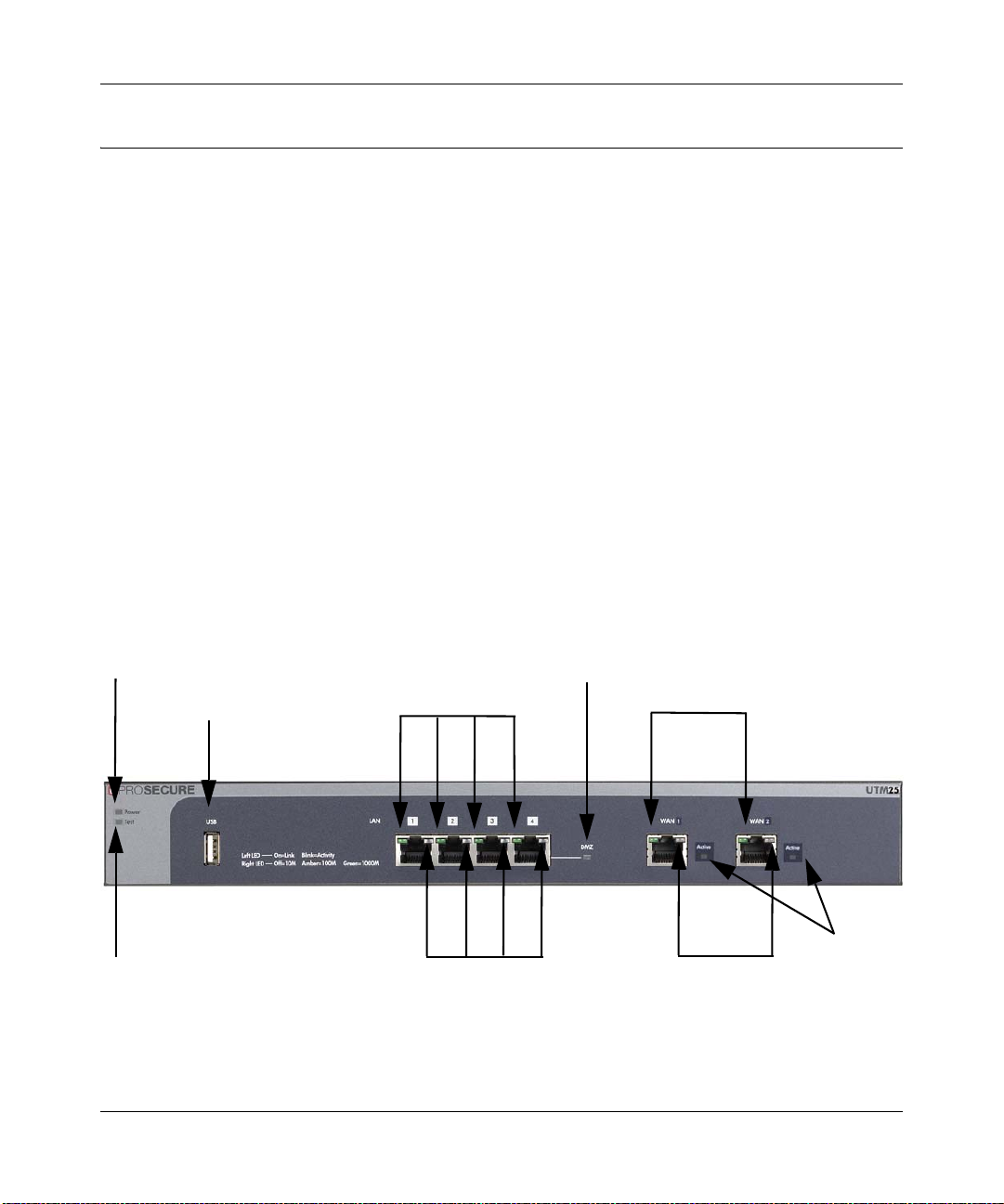
Power LED
Test LED
Left LAN LEDs
Right LAN LEDs
DMZ LED
Left WAN LEDs
Right WAN LEDs
Active
WAN
LEDs
USB port
Hardware Features
The front panel ports and LEDs, rear panel ports, and bottom label of the UTM are described
below.
Front Panel
Viewed from left to right, the UTM front panel contains the following ports (see Figure 1-2 on
page 1-10, which shows a dual-WAN port model, the UTM25):
• One non-functioning USB port: this port is included for future management enhancements.
The port is currently not operable on the UTM.
• LAN Ethernet ports: four switched N-way automatic speed negotiating, Auto MDI/MDIX,
Gigabit Ethernet ports with RJ-45 connectors.
• WAN Ethernet ports: one (single WAN-port models) or two (dual WAN port models)
independent N-way automatic speed negotiating, Auto MDI/MDIX, Gigabit Ethernet ports
with RJ-45 connectors.
The front panel also contains three groups of status indicator light-emitting diodes (LEDs),
including Power and Test LEDs, LAN LEDs, and WAN LEDs, all of which are explained in
Table 1-2.
Figure 1-2
1-10 Introduction
v1.0, January 2010
Page 29
ProSecure Unified Threat Management (UTM) Appliance Reference Manual
Note: Figure 1-2 shows a dual-WAN port model (the UTM25). Single-WAN port models
contain the left WAN port that is shown in Figure 1-2 but no rig ht WAN port nor
any Active WAN LEDs.
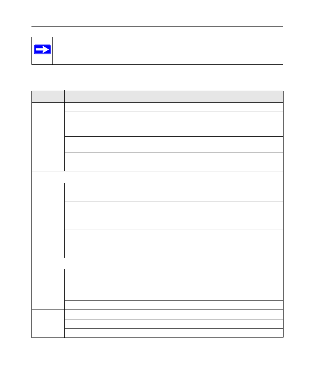
The function of each LED is described in Table 1-2.
Table 1-2. LED Descriptions
Object Activity Description
Power On (Green) Power is supplied to the UTM.
Off Power is not supplied to the UTM.
Test On (Amber) during
startup.
On (Amber) during
any other time
Blinking (Amber) Writing to flash memory (during upgrading or resetting to defaults).
Off The system has booted successfully.
LAN Ports
Left LED Off The LAN port has no link.
On (Green) The LAN port has detected a link with a connected Ethernet device.
Blink (Green) Data is being transmitted or received by the LAN port.
Right LED Off The LAN port is operating at 10 Mbps.
On (Amber) The LAN port is operating at 100 Mbps.
On (Green) The LAN port is operating at 1000 Mbps.
DMZ LED Of f Port 4 is operating as a normal LAN port.
On (Green) Port 4 is operating as a dedicated hardware DMZ port.
Test mode: The UTM is initializing. After approximately 2 minutes,
when the UTM has completed its initialization, the Test LED goes off.
The initialization has failed or a hardware failure has occurred.
WAN Ports
Left LED Off The WAN port has no physical link, that is, no Ethernet cable is
plugged into the UTM.
On (Green) The WAN port has a valid connection with a device that provides an
Internet connection.
Blink (Green) Data is being transmitted or received by the WAN port.
Right LED Off The WAN port is operating at 10 Mbps.
On (Amber) The WAN port is operating at 100 Mbps.
On (Green) The WAN port is operating at 1000 Mbps.
Introduction 1-11
v1.0, January 2010
Page 30
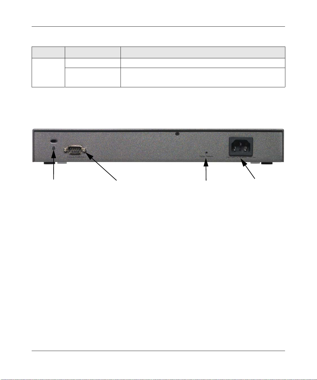
ProSecure Unified Threat Management (UTM) Appliance Reference Manual
Security lock
receptacle
Console port
Reset button
AC power
receptacle
Table 1-2. LED Descriptions (continued)
Object Activity Description
Active LED
(dual-WAN
port models
only)
Off The WAN port is either not enabled or has no link to the Internet.
On (Green) The WAN port has a valid Internet connection.
Rear Panel
The rear panel of the UTM includes a cable lock receptacle, a console port, a reset button, and an
AC power connection.
Figure 1-3
Viewed from left to right, the rear panel contains the following components:
1. Cable security lock receptacle.
2. Console port. Port for connecting to an optional console terminal. The ports has a DB9 male
connector. The default baud rate is 9600 K. The pinouts are: (2) Tx, (3) Rx, (5) and (7) Gnd.
3. Factory default Reset button. Using a sharp object, press and hold this button for about eight
seconds until the front panel Test light flashes to reset the UTM to factory default settings. All
configuration settings are lost and the default password is restored.
4. AC power receptacle. Universal AC input (100-240 VAC, 50-60 Hz).
Bottom Panel With Product Label
The product label on the bottom of the UTM’s enclosure displays factory default, regulatory
compliance, and other information (see Figure 1-4 and Figure 1-5 on page 1-13 and Figure 1-6 on
page 1-14).
1-12 Introduction
v1.0, January 2010
Page 31

ProSecure Unified Threat Management (UTM) Appliance Reference Manual
Figure 1-4 shows the product label for the UTM5.
Figure 1-4
Figure 1-5 shows the product label for the UTM10.
Figure 1-5
Introduction 1-13
v1.0, January 2010
Page 32

ProSecure Unified Threat Management (UTM) Appliance Reference Manual
Figure 1-6 shows the product label for the UTM25.
Figure 1-6
Choosing a Location for the UTM
The UTM is suitable for use in an office environment where it can be free-standing (on its runner
feet) or mounted into a standard 19-inch equipment rack. Alternatively, you can rack-mount the
UTM in a wiring closet or equipment room. A rack mounting kit, containing two mounting
brackets and four screws, is provided in the package for the dual-WAN port models.
Consider the following when deciding where to position the UTM:
• The unit is accessible and cables can be connected easily.
• Cabling is away from sources of electrical noise. These include lift shafts, microwave ovens,
and air-conditioning units.
• Water or moisture cannot enter the case of the unit.
• Airflow around the unit and through the vents in the side of the case is not restricted. Provide a
minimum of 25 mm or 1 inch clearance.
• The air is as free of dust as possible.
1-14 Introduction
v1.0, January 2010
Page 33

ProSecure Unified Threat Management (UTM) Appliance Reference Manual
• Temperature operating limits are not like l y to be exceeded. Install the unit in a clean, airconditioned environment. For information abou t the recommen ded operatin g temperatures for
the UTM, see Appendix A, “Default Settings and Technical Specifications.”
Using the Rack-Mounting Kit
Use the mounting kit for the UTM to install the appliance in a rack. (A mounting kit is provided in
the package for the dual-WAN port models). Attach the mounting brackets using the hardware that
is supplied with the mounting kit.
Figure 1-7
Before mounting the UTM in a rack, verify that:
• You have the correct screws (supplied with the installation kit).
• The rack onto which you will mount the UTM is suitably located.
Introduction 1-15
v1.0, January 2010
Page 34

ProSecure Unified Threat Management (UTM) Appliance Reference Manual
1-16 Introduction
v1.0, January 2010
Page 35

Chapter 2
Using the Setup Wizard to Provision the UTM in
Your Network
Understanding the Steps for Initial Connection
Typically, the UTM is installed as a network gateway to function as a combined LAN switch,
firewall, and content scan engine in order to protect the network from all incoming and outgoing
malware threats.
Generally, five steps are required to complete the basic and security configuration of your UTM:
1. Connect the UTM physically to your network. Connect the cables and restart your network
according to the instructions in the installation guide. See the ProSecure Unified Threat
Management UTM Installation Guide for complete steps. A PDF of the Installation Guide is
on the NETGEAR website at http://prosecure.netgear.com or
http://kb.netgear.com/app/home.
2. Log in to the UTM. After logging in, you are ready to set up and configure your UTM. See
“Logging In to the UTM” on page 2-2.
3. Use the Setup Wizard to configure basic connections and security. During this phase, you
connect the UTM to one or more ISPs (more than one ISP applies to dual-WAN port models
only). See “Using the Setup Wizard to Perform the Initial Configuration” on page 2-7.
4. Verify the installation. See “Verifying Proper Installation” on page 2-26.
5. Register the UTM. “Registering the UTM with NETGEAR” on page 2-26.
Each of these tasks is described separately in this chapter. The configuration of the WAN mode
(required for dual-WAN port models only), dynamic DNS, and other WAN options is described in
Chapter 3, “Manually Configuring Internet and WAN Settings.”
The configuration of LAN, firewall, scanning, VPN, management, and monitoring features is
described in later chapters.
2-1
v1.0, January 2010
Page 36

ProSecure Unified Threat Management (UTM) Appliance Reference Manual
Qualified Web Browsers
To configure the UTM, you must use a Web browser such as Microsoft Internet Explorer 6 or
higher, Mozilla Firefox 3 or higher, or Apple Safari 3 or higher with JavaScript, cookies, and you
must have SSL enabled.
Although these web browsers are qualified for use with the UTM’s Web Management Interface,
SSL VPN users should choose a browser that supports JavaScript, Java, cookies, SSL, and
ActiveX to take advantage of the full suite of applications. Note that Java is only required for the
SSL VPN portal, not for the Web Management Interface.
Logging In to the UTM
To connect to the UTM, your computer needs to be configured to obtain an IP address
automatically from the UTM via DHCP. For instructions on how to configure your computer for
DHCP, see the document that you can access from “Preparing Your Network” in Appendix E.
To connect and log in to the UTM:
1. Start any of the qualified Web browsers, as explained in “Qualified Web Browsers” on this
page.
2. Enter https://192.168.1.1 in the address field. The NETGEAR Configuration Manager Login
screen displays in the browser (see Figure 2 - 1 on page 2-3, which shows a dual-WAN port
model, the UTM25).
Note: The UTM factory default IP address is 192.168.1.1. If you change the IP
address, you must use the IP address that you assigned to the UTM to log in to
the UTM.
2-2 Using the Setup Wizard to Provision the UTM in Your Network
v1.0, January 2010
Page 37

ProSecure Unified Threat Management (UTM) Appliance Reference Manual
Figure 2-1
Note: The first time that you remotely connect to the UTM with a browser via an SSL
connection, you might get a warning message regarding the SSL certificate.
You can follow to directions of your browser to accept the SSL certificate, or
you can import the UTM’s root certificate by clicking the hyperlink at the he
bottom of the NETGEAR Configuration Manager Login screen.
3. In the User field, type admin. Use lower case letters.
4. In the Password field, type password. Here too, use lower case letters.
Note: The UTM user name and password are not the same as any user name or
password you might use to log in to your Internet connection.
Using the Setup Wizard to Provision the UTM in Your Network 2-3
v1.0, January 2010
Page 38

ProSecure Unified Threat Management (UTM) Appliance Reference Manual
5. Click Login. The Web Management Interface appears, displaying the System Status screen.
(Figure 2-2 on page 2-4 shows the top part of a dual-W AN port model screen. For information
about this screen, see “V iewing System Status” on page 11-20).
Note: After 5 minutes of inactivity (the default login time-out), you are automatically
logged out.
Figure 2-2
2-4 Using the Setup Wizard to Provision the UTM in Your Network
v1.0, January 2010
Page 39

ProSecure Unified Threat Management (UTM) Appliance Reference Manual
1st Level: Main Navigation Menu Link (orange)
2nd Level: Configuration Menu Link (gray)
3rd Level: Submenu Tab (blue)
Option Arrow: Additional screen for submenu item
Understanding the Web Management Interface Menu Layout
Figure 2-3 shows the menu at the top of a dual-WAN port model’s Web Management Interface (in
this example, the UTM25). The single-WAN port model’s Web Management Interface layo ut is
identical with the exception that it shows only a single WAN ISP Setting submenu tab.
Figure 2-3
The Web Management Interface menu consists of the following components:
• 1st Level: Main navigation menu links. The main navigation menu in the orange bar across
the top of the Web Management Interface provide access to all the configuration functions of
the UTM, and remain constant. When you select a main navigation menu link, the letters are
displayed in white against an orange background.
• 2nd Level: Configuration menu links. The configuration menu links in the gray bar
(immediately below the main navigation menu bar) change according to the main navigation
menu link that you select. When you select a configuration menu link, the letters are displayed
in white against a grey background.
• 3rd Level: Submenu tabs. Each configuration menu item has one or more submenu tabs that
are listed below the grey menu bar. When you select a submenu tab, the text is displayed in
white against a blue background.
• Option arrows. If there are additional screens for the submenu item, they are displayed on the
right side in blue letters against a white background, preceded by a white arrow in a blue
circle.
Using the Setup Wizard to Provision the UTM in Your Network 2-5
v1.0, January 2010
Page 40

ProSecure Unified Threat Management (UTM) Appliance Reference Manual
The bottom of each screen provides action buttons. The nature of the screen determines which
action buttons are shown. Figure 2-4 shows an example.
Figure 2-4
Any of the following action buttons might be displayed on screen (this list might not be complete):
• Apply. Save and ap ply the configuration.
• Reset. Reset the configuration to default values.
• Test. Test the configuration before you decide whether or not to save and apply the
configuration.
• Auto Detect. Enable the UTM to detect the configuration automatically and suggest values for
the configuration.
• Next. Go to the next screen (for wizards).
• Back. Go to the previous screen (for wizards).
• Search. Perform a search operation.
• Cancel. Cancel the operation.
• Send Now. Send a file or report.
When a screen includes a table, table buttons are displayed to let you configure the table entries.
The nature of the screen determines which table buttons are shown. Figure 2-5 shows an example.
Figure 2-5
Any of the following table buttons might be displayed on screen:
• Select All. Select all entries in the table.
• Delete. Delete the selected entry or entries from the table.
• Enable. Enable the selected entry or entries in the table.
• Disable. Disable the selected entry or entries in the table.
• Add. Add an entry to the table.
• Edit. Edit the selected entry.
• Up. Move up the selected entry in the table.
2-6 Using the Setup Wizard to Provision the UTM in Your Network
v1.0, January 2010
Page 41

ProSecure Unified Threat Management (UTM) Appliance Reference Manual
• Down. Move down the selected entry in the table.
• Apply. Apply the selected entry.
Almost all screens and sections of screens have an accompanyning help screen. To open the help
screen, click the question mark icon. ( ).
Using the Setup Wizard to Perform the Initial Configuration
The Setup Wizard facilitates the initial configuration of the UTM by taking you through ten
screens, the last of which allows you to save the configuration. If you prefer to perform the initial
WAN setup manually, see Chapter 3, “Manually Configuring Internet and WAN Settings.”
To start the Setup Wizard:
1. Select Wizards from the main navigation menu. The “Welcome to the Netgear Configuration
Wizard” scre en displays.
Figure 2-6
2. Select the Setup Wizard radio button.
3. Click Next.The first Setup Wizard screen displays.
The following sections explain the nine configuration screens of the Setup Wizard. On the 10th
screen, you can save your configuration.
The tables in the following sections explain the buttons and fields of the Setup Wizard screens.
Additional information about the settings in the Setup W izard screens is provided in other chapters
that explain manual configuration; each section below provides a specific link to a section in
another chapters.
Using the Setup Wizard to Provision the UTM in Your Network 2-7
v1.0, January 2010
Page 42

ProSecure Unified Threat Management (UTM) Appliance Reference Manual
Setup Wizard Step 1 of 10: LAN Settings
Figure 2-7
Enter the settings as explained in Table 2-1 on page 2-9, then click Next to go the following
screen.
Note: In this first step, you are actually configuring the LAN settings for the UTM’s
default VLAN. For more information about VLANs, see “Managing Virtual LANs
and DHCP Options” on page 4-1.
Note: After you have completed the steps in the Setup Wizard, you can make changes to
the LAN settings by selecting Network Config > LAN Settings > Edit LAN
Profile. For more information about these LAN settings, see “VLAN DHCP
Options” on page 4-4.
2-8 Using the Setup Wizard to Provision the UTM in Your Network
v1.0, January 2010
Page 43

ProSecure Unified Threat Management (UTM) Appliance Reference Manual
Table 2-1. Setup Wizard Step 1: LAN Settings
Setting Description (or Subfield and Description)
LAN TCP/IP Setup
IP Address Enter the IP address of the UTM’s default VLAN (the factory default is
192.168.1.1).
Note: Always make sure that the LAN port IP address and DMZ port IP address
are in different subnets.
Note: If you change the LAN IP address of the UTM‘s default VLAN while being
connected through the browser, you will be disconnected. You must then open a
new connection to the new IP address and log in again. For example, if you
change the default IP address from 192.168.1.1 to 10.0.0.1, you must now enter
https://10.0.0.1 in your browser to reconnect to the Web Management
Interface.
Subnet Mask Enter the IP subnet mask. The subnet mask specifies the network number
portion of an IP address. The UTM automatically calculates the subnet mask
based on the IP address that you assign. Unless you are implementing
subnetting, use 255.255.255.0 as the subnet mask (computed by the UTM).
DHCP
Disable DHCP Server If another device on your network is the DHCP server for the default VLAN, or if
you will manually configure the network settings of all of your computers, select
the Disable DHCP Server radio button to disable the DHCP server. This is the
default setting.
Enable DHCP Server Select the Enable DHCP Server radio button to enable the UTM to function as
a Dynamic Host Configuration Protocol (DHCP) server, providing TCP/IP
configuration for all computers connected to the default VLAN. Enter the
following settings:
Domain Name This is optional. Enter the domain name of the UTM.
Starting IP
Address
Ending IP
Address
Enter the starting IP address. This address specifies the first of
the contiguous addresses in the IP address pool. Any new
DHCP client joining the LAN is assigned an IP address
between this address and the Ending IP Address. The IP
address 192.168.1.2 is the default start address.
Enter the ending IP address. This address specifies the last of
the contiguous addresses in the IP address pool. Any new
DHCP client joining the LAN is assigned an IP address
between the Starting IP address and this IP address. The IP
address 192.168.1.100 is the default ending address.
Note: The starting and ending DHCP IP addresses should be
in the same “network” as the LAN TCP/IP address of the UTM
(the IP address in LAN TCP/IP section above).
Using the Setup Wizard to Provision the UTM in Your Network 2-9
v1.0, January 2010
Page 44

ProSecure Unified Threat Management (UTM) Appliance Reference Manual
Table 2-1. Setup Wizard Step 1: LAN Settings (continued)
Setting Description (or Subfield and Description)
Enable DHCP Server
(continued)
DHCP Relay Select the DHCP Relay radio button to use the UTM as a DHCP relay agent for
Enable LDAP information Select the Enable LDAP information checkbox to enable the DHCP server to
Primary DNS
Server
Secondary
DNS Server
WINS Server This is optional. Enter a WINS server IP address to specify the
Lease Time Enter a lease time. This specifies the duration fo r which IP
a DHCP server somewhere else on your network. Enter the following setting:
Relay
Gateway
provide Lightweight Directory Access Protocol (LDAP) server information. Enter
the settings below.
Note: The LDAP settings that you specify as part of the VLAN profile are used
only for SSL VPN and UTM authentication, but not for Web and e-mail security.
LDAP Server The IP address or name of the LDAP server.
Search Base The search objects that specify the location in the directory
port The port number for the LDAP server. The default setting is
This is optional. If an IP address is specified, the UTM provides
this address as the primary DNS server IP address. If no
address is specified, the UTM provides its own LAN IP address
as the primary DNS server IP address.
This is optional. If an IP address is specified, the UTM provides
this address as the secondary DNS server IP address.
Windows NetBios server, if one is present in your network.
addresses are leased to clients.
The IP address of the DHCP server for which the UTM serves
as a relay.
tree from which the LDAP search begin. You can specify
multiple search object, separated by commas. The search
objects include:
• cn (for common name)
• ou (for organizational unit)
• o (for organization)
• c (for country)
• dc (for domain)
For example, to search the Netgear.net domain for all last
names of Johnson, you would enter:
cn=Johnson,dc=Netgear,dc=net
zero.
2-10 Using the Setup Wizard to Provision the UTM in Your Network
v1.0, January 2010
Page 45
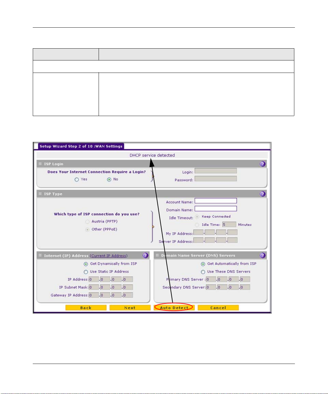
ProSecure Unified Threat Management (UTM) Appliance Reference Manual
Table 2-1. Setup Wizard Step 1: LAN Settings (continued)
Setting Description (or Subfield and Description)
DNS Proxy
Enable DNS Proxy This is optional. Select the Enable DNS Proxy radio button to enable the UTM
to provide a LAN IP address for DNS address name resolution. This setting is
enabled by default.
Note: When you deselect the Enable DNS Proxy radio button, the UTM still
services DNS requests that are sent to its LAN IP address unless you disable
DNS Proxy in the firewall settings (see “Attack Checks” on page 5-27).
Setup Wizard Step 2 of 10: WAN Settings
Figure 2-8
Enter the settings as explained in Table 2-2 on page 2-12, then click Next to go the following
screen.
Using the Setup Wizard to Provision the UTM in Your Network 2-11
v1.0, January 2010
Page 46

ProSecure Unified Threat Management (UTM) Appliance Reference Manual
Note: Click the Auto Detect action button at the bottom of the menu. The auto-detect
process probes the WAN port for a range of connection methods and suggests one
that your ISP is most likely to support.
Note: After you have completed the steps in the Setup Wizard, you can make changes to
the WAN settings by selecting Network Config > WAN Settings. Then, for a
dual-WAN port model, select WAN1 ISP Settings or WAN2 ISP Settings, and for
a single-WAN port model, select WAN ISP Settings. For more information about
these WAN settings, see “Configuring the Internet Connections” on page 3-2.
Table 2-2. Setup Wizard Step 2: WAN Settings
Setting Description (or Subfield and Description)
ISP Login
Does your Internet
connection require a
login?
ISP Type
What type of ISP
connection do you
use?
Austria (PPTP) If your ISP is Austria Telecom or any other ISP that uses PPTP for login, select this
If you need to enter login information every time you connect to the Internet through
your ISP, select the Yes radio button. Otherwise, select the No radio button, which
is the default setting, and skip the ISP Type section below. If you select Yes, enter
the following settings:
Login The login name that your ISP has assigned to you.
Password The password that your ISP has assigned to you.
If your connection is PPPoE or PPTP, then you must log in. Select the Yes radio
button. Based on the connection that you select, the text box fields that require
data entry are highlighted. If your ISP has not assigned any login information, then
select the No radio box and skip this section. If you select Yes, enter the following
settings:
radio button and enter the following settings:
Account Name The account name is also known as the host name or
system name. Enter the valid account name for the PPTP
connection (usually your email “ID” assigned by your ISP).
Some ISPs require entering your full e-mail address here.
Domain Name Your domain name or workgroup name assigned by your
ISP, or your ISP’s domain name. You may leave this field
blank.
2-12 Using the Setup Wizard to Provision the UTM in Your Network
v1.0, January 2010
Page 47

ProSecure Unified Threat Management (UTM) Appliance Reference Manual
Table 2-2. Setup Wizard Step 2: WAN Settings (continued)
Setting Description (or Subfield and Description)
Austria (PPTP)
(continued)
Other (PPPoE) If you have installed login software such as WinPoET or Enternet, then your
Internet (IP) Address
Click the Current IP Address link to see the currently assigned IP address.
Get Dynamically from
ISP
Use Static IP Address If your ISP has assigned you a fixed (static or permanent) IP address, select the
Idle Timeout Select the Keep Connected radio button to keep the
connection always on. To log out after the connection is
idle for a period of time, select the Idle Time radio button
and, in the timeout field, enter the number of minutes to
wait before disconnecting. This is useful if your ISP
charges you based on the period that you have logged in.
My IP Address The IP address assigned by the ISP to make the
connection with the ISP server.
Server IP Address The IP address of the PPTP server.
connection type is PPPoE. Select this radio button and enter the following settings:
Account Name The valid account name for the PPPoE connection.
Domain Name The name of your ISP’s domain or your domain name if
your ISP has assigned one. You may leave this field blank.
Idle Timeout Select the Keep Connected radio button to keep the
connection always on. To log out after the connection is
idle for a period of time, select the Idle Time radio button
and, in the timeout field, enter the number of minutes to
wait before disconnecting. This is useful if your ISP
charges you based on the period that you have logged in
If your ISP has not assigned you a static IP address, select the Get dynamically
from ISP radio button. The ISP automatically assigns an IP address to the UTM
using DHCP network protocol.
Use Static IP Address radio button and enter the following settings:
IP Address Static IP address assigned to you. This address identifies
the UTM to your ISP.
Subnet Mask The subnet mask is usually provided by your ISP.
Gateway IP Address The IP address of the ISP’s gateway is usually provided by
your ISP.
Domain Name Server (DNS) Servers
Get Automatically from
ISP
If your ISP has not assigned any Domain Name Servers (DNS) addresses, select
the Get Automatically from ISP radio button.
Using the Setup Wizard to Provision the UTM in Your Network 2-13
v1.0, January 2010
Page 48

ProSecure Unified Threat Management (UTM) Appliance Reference Manual
Table 2-2. Setup Wizard Step 2: WAN Settings (continued)
Setting Description (or Subfield and Description)
Use These DNS
Servers
If your ISP has assigned DNS addresses, select the Use these DNS Servers radio
button. Ensure that you fill in valid DNS server IP addresses in the fields. Incorrect
DNS entries might cause connectivity issues.
Primary DNS Server The IP address of the primary DNS server.
Secondary DNS Serve The IP address of the secondary DNS server.
Setup Wizard Step 3 of 10: System Date and Time
Figure 2-9
Enter the settings as explained in Table 2-3 on page 2-15, then click Next to go the following
screen.
Note: After you have completed the steps in the Setup Wizard, you can make changes to
the date and time by selecting Administration > System Date & Time. For more
information about these settings, see “Configuring Date and Time Service” on
page 10-24.
2-14 Using the Setup Wizard to Provision the UTM in Your Network
v1.0, January 2010
Page 49

ProSecure Unified Threat Management (UTM) Appliance Reference Manual
Table 2-3. Setup Wizard Step 3: System Date and Time Settings
Setting Description (or Subfield and Description)
Set Time, Date and NTP Servers
Date/Time From the pull-down menu, select the local time zone in which the UTM operates.
The proper time zone is required in order for scheduling to work correctly. The
UTM includes a real-time clock (RTC), which it uses for scheduling.
Automatically Adjust for
Daylight Savings Time
NTP Server (default or
custom)
If daylight savings time is supported in your region, select the Automatically
Adjust for Daylight Savings Time checkbox.
From the pull-down menu, select an NTP server:
• Use Default NTP Servers. The UTM’s RTC is updated regularly by contacting a
default Netgear NTP server on the Internet.
• Use Custom NTP Servers. The UTM’s RTC is updated regularly by contacting
one of the two NTP servers (primary and backup), both of which you must
specify in the fields that become available with this menu selection.
Note: If you select this option but leave either the Server 1 or Server 2 field
blank, both fields are set to the default Netgear NTP servers.
Note: A list of public NTP servers is available at
http://ntp.isc.org/bin/view/Servers/WebHome.
Server 1 Name /
IP Address
Server 2 Name /
IP Address
Enter the IP address or host name the primary NTP server.
Enter the IP address or host name the backup NTP server.
Using the Setup Wizard to Provision the UTM in Your Network 2-15
v1.0, January 2010
Page 50

ProSecure Unified Threat Management (UTM) Appliance Reference Manual
Setup Wizard Step 4 of 10: Services
Figure 2-10
Enter the settings as explained in Table 2-4 on page 2-17, then click Next to go the following
screen.
Note: After you have completed the steps in the Setup Wizard, you can make changes to
the security services by selecting Application Security > Services. For more
information about these settings, see “Customizing E-mail Protocol Scan Settings”
on page 6-4 and “Customizing Web Protocol Scan Settings and Services” on
page 6-19.
2-16 Using the Setup Wizard to Provision the UTM in Your Network
v1.0, January 2010
Page 51

ProSecure Unified Threat Management (UTM) Appliance Reference Manual
Table 2-4. Setup Wizard Step 4: Services Settings
Setting Description (or Subfield and Description)
Email
SMTP SMTP scanning is enabled by default
on standard service port 25. To disable any of these services,
POP3 POP3 scanning is enabled by default
on standard service port 110.
IMAP IMAP scanning is enable d by default
on standard service port 143.
Web
deselect the corresponding checkbox.
You can change the standard service
port or add another port in the
corresponding Ports to Scan field.
HTTP HTTP scanning is enabled by default
on standard service port 80.
HTTPS HTTPS scanning is disabled by
default.
FTP FTP scanning is enabled by default
on standard service port 21.
Instant Messaging
Google Talk (Jabber)
Yahoo Messenger
mIRC
MSN Messenger
Peer-to-Peer (P2P)
BitTorrent
eDonkey
Gnutella
Scanning of these instant messaging services is disabled by default. To enable
any of these services, select the corresponding checkbox.
Note: For Instant Messaging services, the following services can be blocked:
logging in, sharing files, sharing video, sharing audio, and text messaging.
Scanning of these file-sharing applications is disabled by default. To enable any
of these services, select the corresponding checkbox.
To disable HTTP scanning, deselect the
corresponding checkbox. You can
change the standard service port or add
another port in the corresponding Ports
to Scan field.
To enable HTTPS scanning, select the
corresponding checkbox. You can
change the standard service port (port
443) or add another port in the
corresponding Ports to Scan field.
To disable FTP scanning, deselect the
corresponding checkbox. You can
change the standard service port or add
another port in the corresponding Ports
to Scan field.
Using the Setup Wizard to Provision the UTM in Your Network 2-17
v1.0, January 2010
Page 52

ProSecure Unified Threat Management (UTM) Appliance Reference Manual
Setup Wizard Step 5 of 10: Email Security
Figure 2-11
Enter the settings as explained in Table 2-5, then click Next to go the following screen.
Note: After you have completed the steps in the Setup Wizard, you can make changes to
the email security settings by selecting Application Security > Email Anti-V irus.
The Email Anti-Virus screen also lets you specify notification settings and email
alert settings. For more information about these settings, see “Customizing E-mail
Anti-V irus and Notificatio n Settings” on page 6-5.
Table 2-5. Setup Wizard Step 5: Email Security Settings
Setting Description (or Subfield and Description)
Action
SMTP From the SMTP pull-down menu, specify one of the following actions when an
infected e-mail is detected:
• Block infected email. This is the default setting. The e-mail is blocked, and a
log entry is created.
• Delete attachment.The e-mail is not blocked, but the attachment is deleted,
and a log entry is created.
• Log only. Only a log entry is created. The e-mail is not blocked and the
attachment is not deleted.
POP3 From the POP3 pull-down menu, specify one of the following actions when an
infected e-mail is detected:
• Delete attachment. This is the default setting. The e-mail is not blocked, but
the attachment is deleted, and a log entry is created.
• Log only. Only a log entry is created.The e-mail is not blocked and the
attachment is not deleted.
2-18 Using the Setup Wizard to Provision the UTM in Your Network
v1.0, January 2010
Page 53

ProSecure Unified Threat Management (UTM) Appliance Reference Manual
Table 2-5. Setup Wizard Step 5: Email Security Settings (continued)
Setting Description (or Subfield and Description)
IMAP From the IMAP pull-down menu, specify one of the following actions when an
infected e-mail is detected:
• Delete attachment. This is the default setting. The e-mail is not blocked, but
the attachment is deleted, and a log entry is created.
• Log only. Only a log entry is created. The e-mail is not blocked and the
attachment is not deleted.
Scan Exceptions
The default maximum file or message size that is scanned is 2048 KB, but you can define a maximum size
of up to 10240 KB. However, setting the maximum size to a high value might affect the UTM's performance
(see “Performance Management” on page 10-1).
From the pull-down menu, specify one of the following actions when the file or message exceeds the
maximum size:
• Skip. The file is not scanned but skipped, leaving the end user vulnerable. This is the default setting.
• Block. The file is blocked and does not reach the end user.
Setup Wizard Step 6 of 10: Web Security
Figure 2-12
Enter the settings as explained in Table 2-6 on page 2-20, then click Next to go the following
screen.
Using the Setup Wizard to Provision the UTM in Your Network 2-19
v1.0, January 2010
Page 54

ProSecure Unified Threat Management (UTM) Appliance Reference Manual
Note: After you have completed the steps in the Setup Wizard, you can make changes to
the Web security settings by selecting Application Security > HTTP/HTTPS >
Malware Scan. The Malware Scan screen also lets you specify HTML scanning
and notification settings. For more information about these settings, see
“Configuring Web Malware Scans” on page 6-21.
Table 2-6. Setup Wizard Step 6: Web Security Settings
Setting Description (or Subfield and Description)
Action
HTTP From the HTTP pull-down menu, specify one of the following actions when an
infected Web file or object is de te cted:
• Delete file. This is the default setting. The Web file or object is deleted, and a
log entry is created.
• Log only. Only a log entry is created. The Web file or object is not deleted.
Select the Streaming checkbox to enable streaming of partially downloaded
and scanned HTTP file parts to the user. This method allows the user to
experience more transparent Web downloading. Streaming is enabled by
default.
HTTPS From the HTTPS pull-down menu, specify one of the following actions when an
infected Web file or object is de te cted:
• Delete file. This is the default setting. The Web file or object is deleted, and a
log entry is created.
• Log only. Only a log entry is created. The Web file or object is not deleted.
Select the Streaming checkbox to enable streaming of partially downloaded
and scanned HTTPS file parts to the user. This method allows the user to
experience more transparent Web downloading. Streaming is enabled by
default.
FTP From the FTP pull-down menu, specify one of the following actions when an
infected FTP file or object is detected:
• Delete file. This is the default setting. The FTP file or object is deleted, and a
log entry is created.
• Log only. Only a log entry is created. The FTP file or object is not deleted.
Scan Exceptions
The default maximum file or object size that are scanned is 2048 KB, but you can define a maximum size of
up to 10240 KB. However, setting the maximum size to a high value might affect the UTM's performance
(see “Performance Management” on page 10-1).
From the pull-down menu, specify one of the following actions when the file or message exceeds the
maximum size:
• Skip. The file is not scanned but skipped, leaving the end user vulnerable. This is the default setting.
• Block. The file is blocked and does reach the end user.
2-20 Using the Setup Wizard to Provision the UTM in Your Network
v1.0, January 2010
Page 55

ProSecure Unified Threat Management (UTM) Appliance Reference Manual
Setup Wizard Step 7 of 10: Web Categories to Be Blocked
Figure 2-13
Using the Setup Wizard to Provision the UTM in Your Network 2-21
v1.0, January 2010
Page 56

ProSecure Unified Threat Management (UTM) Appliance Reference Manual
Enter the settings as explained in Table 2-7, then click Next to go the following screen.
Note: After you have completed the steps in the Setup Wizard, you can make changes to
the content filtering settings by selecting Application Security > HTTP/HTTPS
> Content Filtering. The Content Filtering screen lets you specify additional
filtering tasks and notification settings. For more information about these settings,
see “Configuring Web Content Filtering” on page 6-23.
Table 2-7. Setup Wizard Step 7: Content Filtering Settings
Setting Description (or Subfield and Description)
Blocked Web Categories
Select the Enable Blocking checkbox to enable blocking of Web categories. By default, this checkbox is
deselected.
Select the checkboxes of any Web categories that you want to block. Use the action buttons at the top of
the section in the following way:
• Allow All. All Web categories are allowed.
• Block All. All Web categories are blocked.
• Set to Defaults. Blocking and allowing of Web categories are returned to their default settings. See
Table 6-1 on page 6-2 for information about the Web categories that are blocked by default. Categories
that are preceded by a green rectangular are allowed by default; categories that are preceded by a pink
rectangular are blocked by default.
Blocked Categories Scheduled Days
Make one of the following selections:
• Select the All Days radio button to enable content filtering to be active all days of the week.
• Select the Specific Days radio button to enable content filtering to be active on the days that are specified
by the checkboxes.
Blocked Categories Time of Day
Make one of the following selections:
• Select the All Day radio button to enable content filtering to be active all 24 hours of each selected day.
• Select the Specific Times radio button to enable content filtering to be active during the time that is
specified by the Start Time and End Time fields for each day that content filtering is active.
2-22 Using the Setup Wizard to Provision the UTM in Your Network
v1.0, January 2010
Page 57

ProSecure Unified Threat Management (UTM) Appliance Reference Manual
Setup Wizard Step 8 of 10: Email Notification
Figure 2-14
Enter the settings as explained in Table 2-8, then click Next to go the following screen.
Note: After you have completed the steps in the Setup Wizard, you can make changes to
the administrator email notification settings by selecting Network Config > Email
Notification. For more information about these settings, see
“Configuring the E-mail Notification Server” on page 11-5.
Table 2-8. Setup Wizard Step 8: Administrator Email Notification Settings
Setting Description (or Subfield and Description)
Administrator Email Notification Settings
Show as mail sender A descriptive name of the sender for e-mail identification purposes. For
example, enter UTM_Notifications@netgear.com.
SMTP server The IP address and port number or Internet name and port number of your
ISP’s outgoing e-mail SMTP server. The default port number is 25.
Note: If you leave this field blank, the UTM cannot send e-mail notifications.
This server requires
authentication
Send notifications to The email address to which the notifications should be sent. Typically , this is the
If the SMTP server requires authentication, select the This server requires
authentication checkbox and enter the following settings:
User name The user name for SMTP server authentication.
Password The password for SMTP server authentication.
e-mail address of the administrator.
Using the Setup Wizard to Provision the UTM in Your Network 2-23
v1.0, January 2010
Page 58

ProSecure Unified Threat Management (UTM) Appliance Reference Manual
Setup Wizard Step 9 of 10: Signatures & Engine
Figure 2-15
Enter the settings as explained in Table 2-9 on page 2-25, then click Next to go the following
screen.
Note: After you have completed the steps in the Setup Wizard, you can make changes to
the signatures and engine settings by selecting Administration > System Update
> Signatures and Engine. For more information about these settings, see
“Updating the Scan Signatures and Scan Engine Firmware” on page 10-21.
2-24 Using the Setup Wizard to Provision the UTM in Your Network
v1.0, January 2010
Page 59

ProSecure Unified Threat Management (UTM) Appliance Reference Manual
Table 2-9. Setup Wizard Step 9: Signatures & Engine Settings
Setting Description (or Subfield and Description)
Update Settings
Update From the pull-down menu, select one of the following options:
• Never. The pattern and firmware files are never automatically updated.
• Scan engine and Signatures. The pattern and firmware files are
automatically updated according to the Update Frequency settings below.
Update From Set the update source server by selecting one of the following radio buttons:
• Default update server. Files are updated from the default NETGEAR update
server.
• Server address. Files are updated from the server that you specify: enter the
IP address or host name of the update server.
Update Frequency
Specify the frequency with which the UTM checks for file updates:
• Weekly. From the pull-down menus, select the weekday, hour, and minutes that the updates occur.
• Daily. From the pull-down menus, select the hour, and minutes th at the updates occur.
• Every. From the pull-down menu, select the frequency with which the updates occur. The range is from 15
minutes to 12 hours.
HTTPS Proxy Settings
Enable If computers on the network connect to the Internet via a proxy server, select
the Enable checkbox to specify and enable a proxy server. Enter the following
settings:
Proxy server The IP address and port number of the proxy server.
User name The user name for proxy server authentication.
Password The password for proxy server authentication.
Setup Wizard Step 10 of 10: Saving the Configuration
Figure 2-16
Click Apply to save your settings and automatically restart the system.
Using the Setup Wizard to Provision the UTM in Your Network 2-25
v1.0, January 2010
Page 60

ProSecure Unified Threat Management (UTM) Appliance Reference Manual
Verifying Proper Installation
Test the UTM before deploying it in a live production environment. The following instructions
walk you through a couple of quick tests that are designed to ensure that your UTM is functioning
correctly.
Testing Connectivity
Verify that network traffic can pass through the UTM:
• Ping an Internet URL.
• Ping the IP address of a device on either side of the UTM.
Testing HTTP Scanning
If client computers have direct access to the Internet through your LAN, try to download the
eicar.com test file from http://www.eicar.org/download/eicar.com.
The eicar.com test file is a legitimate DoS program and is safe to use because it is not a malware
threat and does not include any fragments of malware code. The test file is provided by EICAR, an
organization that unites efforts against computer crime, fraud, and misuse of computers or
networks.
Verify that the UTM properly scans HTTP traffic:
1. Log in to the UTM Web Management Interface, and then verify that HTTP scanning is
enabled. For information about how to enable HTTP scanning, see “Customizing Web
Protocol Scan Settings and Services” on page 6-19 and “Configuring Web Malware Scans” on
page 6-21.
2. Check the downloaded eicar.com test file, and note the attached malware information file.
Registering the UTM with NETGEAR
To receive threat management component updates and technical support, you must register your
UTM with NETGEAR. The support registration key is provided with the product package (see
“Service Registration Card with License Keys” on page 1-8).
2-26 Using the Setup Wizard to Provision the UTM in Your Network
v1.0, January 2010
Page 61
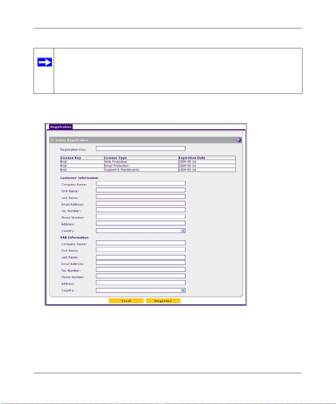
ProSecure Unified Threat Management (UTM) Appliance Reference Manual
Note: Activating the service licenses initiates their terms of use. Activate the licenses
only when you are ready to start using this unit. If your unit has never been
registered before you can use the 30-day trial period for all 3 types of licenses to
perform the initial testing and configuration. To use the trial period, do not click
Register in step 4 of the procedure below but click Trial instead.
If your UTM is connected to the Internet, you can activate the service licenses:
1. Select Support > Registration. The Registration screen displays.
Figure 2-17
2. Enter the license key in the Registration Key field.
3. Fill out the customer and VAR fields.
4. Click Register.
Using the Setup Wizard to Provision the UTM in Your Network 2-27
v1.0, January 2010
Page 62

ProSecure Unified Threat Management (UTM) Appliance Reference Manual
5. Repeat step 2 and step 4 for additional license keys.
The UTM activates the licenses and registers the unit with the NETGEAR registration server.
Note: When you reset the UTM to the original factory default settings after you have
entered the license keys to activate the UTM (see “Registering the UTM with
NETGEAR” on page 2-26), the license keys are erased. The license keys and the
different types of licenses that are available for the UTM are no longer displayed
on the Registration screen. However, after you have reconfigured the UTM to
connect to the Internet and to the NETGEAR registration server, the UTM
retrieves and restores all registration information based on its MAC address and
hardware serial number. You do not need to re-ente r the license keys and reactivate the UTM.
What to Do Next
You have completed setting up and deploying the UTM to the network. The UTM is now ready to
scan the protocols and services that you specified and perform automatic updates based on the
update source and frequency that you specified.
If you need to change the settings, or to view reports or logs, log in to the UTM Web Management
Interface, using the default IP address or the IP address that you assigned to the UTM in “Setup
Wizard Step 1 of 10: LAN Settings” on page 2-8.
The UTM is ready for use. However, some important tasks that you might want to address before
you deploy the UTM in your network are listed below:
• “Configuring the WAN Mode (Required for Dual-WAN Port Models Only)” on page 3-9.
• “Configuring VPN Authentication Domains, Groups, and Users” on page 9-1.
• “Managing Digital Certificates” on page 9-17.
• “Using the IPsec VPN Wizard for Client and Gateway Configurations” on page 7-3.
• “Using the SSL VPN Wizard for Client Configurations” on page 8-2.
2-28 Using the Setup Wizard to Provision the UTM in Your Network
v1.0, January 2010
Page 63

Chapter 3
Manually Configuring Internet and WAN Settings
Note: The initial Internet configuration of the UTM is described in Chapter 2, “Using the
Setup Wizard to Provision the UTM in Your Network.” If you used the Setup
Wizard to configure your Internet sett ings, you need this chapte r only to configure
WAN features such as Dual W AN and Dynamic DNS, and to configure secondary
WAN addresses and advanced WAN options.
This chapter contains the following sections:
• “Understanding the Internet and WAN Configuration Tasks” on this page.
• “Configuring the Internet Connections” on page 3-2.
• “Configuring the WAN Mode (Required for Dual-WAN Port Models Only)” on page 3-9.
• “Configuring Secondary WAN Addresses” on page 3-17.
• “Configuring Dynamic DNS” on page 3-19.
• “Configuring Advanced WAN Options” on page 3-22.
Understanding the Internet and WAN Configuration Tasks
Generally, five steps are required to complete the Internet connection of your UTM:
1. Configure the Internet connections to your ISP(s). During this phase, you connect to your
ISPs. You can also program the WAN traffic meters at this time if desired. See “Configuring
the Internet Connections” on page 3-2.
2. Configure the WAN mode (required for operation of the dual-WAN port models). For all
models, select either NAT or classical routing. For the dual-WAN port models only, select
either dedicated (single WAN) mode, auto-rollover mode, or load balancing mode. For load
balancing, you can also select any necessary protocol bindings. See “Configuring the WAN
Mode (Required for Dual-WAN Port Models Only)” on page 3-9.
3. Configure secondary WAN addresses on the WAN ports (optional). Configure aliases for
each WAN port. See “Configuring Secondary WAN Addresses” on page 3-17.
3-1
v1.0, January 2010
Page 64

ProSecure Unified Threat Management (UTM) Appliance Reference Manual
4. Configure dynamic DNS on the WAN ports (optional). Configure your fully qualified
domain names during this phase (if required). See “Configuring Dynamic DNS” on page 3-19.
5. Configure the WAN options (optional). Optionally, you can enable each WAN port to
respond to a ping, and you can change the factory default MTU size and port speed. However ,
these are advanced features and changing them is not usually required. See “Configuring
Advanced WAN Options” on page 3-22.
Each of these tasks is detailed separately in this chapter.
Note: For information about how to configure the WAN meters, see “Enabling the WAN
Traffic Meter” on page 11-1.
Configuring the Internet Connections
Note: The initial Internet configuration of the UTM is described in Chapter 2, “Using the
Setup Wizard to Provision the UTM in Your Network.” If you used the Setup
Wizard to configure your Internet settings, you need this section only if you want
to make changes to your Internet connections.
To set up your UTM for secure Internet connections, you configure WAN ports 1 and 2. The Web
Configuration Manager offers two connection configuration options:
• Automatic detection and configuration of the network connection.
• Manual configuration of the network connection.
Each option is detailed in the sections following.
Automatically Detecting and Connecting
To automatically configure the WAN ports for connection to the Internet:
1. Select Network Config > WAN Settings from the menu. On dual-WAN port models, the
WAN Settings tabs appear, with the WAN1 ISP Settings screen in view (see Figure 3-1 on
page 3-3). On the single-WAN port models, the WAN ISP screen displays.
3-2 Manually Configuring Internet and WAN Settings
v1.0, January 2010
Page 65

ProSecure Unified Threat Management (UTM) Appliance Reference Manual
Figure 3-1
2. Click the Auto Detect action button at the bottom of the menu. The auto-detect process probes
the WAN port for a range of connection methods and suggests one that your ISP is most likely
to support. (Figure 3-2 shows a dual-WAN port model’s screen. A single-WAN port model’s
screen shows only a single WAN ISP Settings submenu tab.)
Figure 3-2
Manually Configuring Internet and WAN Settings 3-3
v1.0, January 2010
Page 66

ProSecure Unified Threat Management (UTM) Appliance Reference Manual
The auto-detect process will return one of the following results:
• If the auto-detect process is successful, a status bar at the top of the menu displays the
results (see the red text in Figure 3-2 on page 3-3).
• If the auto-detect process senses a connection method that requires input from you, it
prompts you for the information. All methods with their required settings are detailed in
Table 3-1.
Table 3-1. Internet connection methods
Connection Method Data Required
DHCP (Dynamic IP) No data is required.
PPPoE Login (Username, Password); Account Name, Domain Name
PPTP Login (Username, Password), Account Name, Local IP address, and PPTP
Server IP address;
Fixed (Static) IP Static IP address, Subnet, and Gateway IP; and related data supplied by
your ISP.
• If the auto-detect process does not find a connection, you are prompted to either check the
physical connection between your UTM and the cable or DSL line or to check your
UTM’s MAC address. For more information, see “Configuring the WAN Mode (Required
for Dual-WAN Port Models Only)” on page 3-9 and “Troubleshooting the ISP
Connection” on page 12-5.
3. To verify the connection, click the WAN Status option arrow at the top right of the screen. A
popup window appears, displaying the connection status of the WAN port
Figure 3-3
3-4 Manually Configuring Internet and WAN Settings
v1.0, January 2010
Page 67

ProSecure Unified Threat Management (UTM) Appliance Reference Manual
The WAN Status window should show a valid IP address and gateway. If the configuration
was not successful, skip ahead to “Manually Configuring the Internet Connection” on this
page , or see “Troubleshooting the ISP Connection” on page 12-5.
Note: If the configuration process was successful, you are connected to the Internet
through WAN port 1. If you intend to use the dual WAN capabilities of the
UTM25, continue with the configuration process for WAN port 2.
Note: For more information about the WAN Connection Status screen, see “Viewing
the WAN Ports Status” on page 11-27.
4. Click the WAN2 ISP Settings tab (dual-WAN port models only).
5. Repeat the previous steps to automatically detect and configure the WAN2 Internet connection
(dual-WAN port models only).
6. Open the WAN Status window and verify a successful connection
If your WAN ISP configuration was successful, you can skip ahead to “Configuring the WAN
Mode (Required for Dual-WAN Port Models Only)” on page 3-9.
If one or both automatic WAN ISP configurations failed, you can attempt a manual configuration
as described in the following section, or see “Troubleshooting the ISP Connection” on page 12-5.
Setting the UTM’s MAC Address
Each computer or router on your network has a unique 48-bit local Ethernet address. This is also
referred to as the computer’s Media Access Control (MAC) address. The default is set to Use
Default Address. If your ISP requires MAC authentication and another MAC address has been
previously registered with your ISP, then you must enter that address. Setting the UTM’s MAC
address is controlled through the Advanced options on the single WAN-port model’s WAN ISP
Settings screen or the dual WAN-port model’s WAN1 ISP Settings and WAN2 ISP Settings screen
(see“Configuring Advanced WAN Options” on page 3-22).
Manually Configuring the Internet Connection
Unless your ISP automatically assigns your configuration via DHCP, you need to obtain
configuration parameters from your ISP in order to manually establish an Internet connection. The
necessary parameters for various connection types are listed in Table 3-1 on page 3-4.
Manually Configuring Internet and WAN Settings 3-5
v1.0, January 2010
Page 68

ProSecure Unified Threat Management (UTM) Appliance Reference Manual
To manually configure the WAN1 ISP (dual-WAN port models) or WAN ISP (single-WAN port
models) settings:
1. On a dual-WAN port model, select Network Configuration > WAN Settings > WAN1 ISP
Settings. The WAN Settings tabs appear, with the WAN1 ISP Settings screen in view (see
Figure 3-1 on page 3-3 , which shows a dual-WAN port model’s screen). On a single-WAN
port model, select Network Configuration > WAN Settings > WAN ISP Settings. The WAN
ISP Settings screen displays. Figure 3-4 shows the ISP Login section of the screen.
Figure 3-4
2. In the ISP Login section of the screen, select one of the following options:
• If your ISP requires an initial login to establish an Internet connection, click Yes (this is
the default).
• If a login is not required, click No and ignore the Login and Password fields.
3. If you clicked Yes, enter the login name in the Login field and the password in the Password
field. This information is provided by your ISP.
4. In the ISP Type section on the sc reen, select the type of ISP connection that you use from the
three listed options. By default, “Other (PPPoE)” is selected, as shown in Figure 3-5.
Figure 3-5
3-6 Manually Configuring Internet and WAN Settings
v1.0, January 2010
Page 69

ProSecure Unified Threat Management (UTM) Appliance Reference Manual
5. If your connection is PPTP or PPPoE, your ISP requires an initial login. Enter the settings as
explained in Table 3-2.
Table 3-2. PPTP and PPPoE Settings
Setting Description (or Subfield and Description)
Austria (PPTP) If your ISP is Austria Telecom or any other ISP that uses PPTP for login, select this
radio button and enter the following settings:
Account Name The account name is also known as the host name or system
name. Enter the valid account name for the PPTP connection
(usually your e-mail “ID” assigned by your ISP). Some ISPs
require entering your full e-mail address here.
Domain Name Y our domain name or workgroup name assigned by your ISP,
or your ISP’s domain name. You may leave this field blank.
Idle Timeout Select the Keep Connected radio button to keep the
connection always on. To log out after the connection is idle
for a period of time, select the Idle Time radio button and, in
the timeout field, enter the number of minutes to wait before
disconnecting. This is useful if your ISP charges you based
on the period that you have logged in.
My IP Address The IP address assigned by the ISP to make the connection
with the ISP server.
Server IP Address The IP address of the PPTP server.
Other (PPPoE) If you have installed login software such as WinPoET or Enternet, then your
connection type is PPPoE. Select this radio button and enter the following settings:
Account Name The valid account name for the PPPoE connection.
Domain Name The name of your ISP’s domain or your domain name if your
ISP has assigned one. You may leave this field blank.
Idle Timeout Select the Keep Connected radio button to keep the
connection always on. To log out after the connection is idle
for a period of time, select the Idle Time radio button and, in
the timeout field, enter the number of minutes to wait before
disconnecting. This is useful if your ISP charges you based
on the period that you have logged in.
Manually Configuring Internet and WAN Settings 3-7
v1.0, January 2010
Page 70

ProSecure Unified Threat Management (UTM) Appliance Reference Manual
6. Configure the Internet (IP) Address settings as explained in Table 3-3. Click the Current IP
Address link to see the currently assigned IP address.
Figure 3-6
Table 3-3. Internet (IP) Address Settings
Setting Description (or Subfield and Description)
Get Dynamically
from ISP
Use Static IP
Address
If your ISP has not assigned you a static IP address, select the Get dynamically
from ISP radio button. The ISP automatically assigns an IP address to the UTM
using DHCP network protocol.
If your ISP has assigned you a fixed (static or permanent) IP address, select the Use
Static IP Address radio button and enter the following settings:
IP Address Static IP address assigned to you. This address identifies the
UTM to your ISP.
Subnet Mask The subnet mask is usually provided by your ISP.
Gateway IP Address The IP address of the ISP’s gateway is usually provided by
your ISP.
7. Configure the Domain Name Server (DNS) servers settings as explained in Table 3-4 on
page 3-9.
Figure 3-7
3-8 Manually Configuring Internet and WAN Settings
v1.0, January 2010
Page 71

ProSecure Unified Threat Management (UTM) Appliance Reference Manual
Table 3-4. DNS Server Settings
Setting Description (or Subfield and Description)
Get Automatically
from ISP
Use These DNS
Servers
If your ISP has not assigned any Domain Name Servers (DNS) addresses, select
the Get Automatically from ISP radio button.
If your ISP has assigned DNS addresses, select the Use these DNS Servers
radio button. Ensure that you fill in valid DNS server IP addresses in the fields.
Incorrect DNS entries might cause connectivity issues.
Primary DNS Server The IP address of the primary DNS server.
Secondary DNS
Serve
The IP address of the secondary DNS server.
8. Click Test to evaluate your entries. The UTM attempts to make a connection according to the
settings that you entered.
9. Click Apply to save any changes to the WAN1 ISP settings of a dual-WAN port model or
WAN ISP settings of a single-WAN port model. (Or, click Reset to discard any changes and
revert to the previous settings.)
10. For the dual-WAN port models only, if you intend to use a dual WAN mode, click the WAN2
ISP Settings tab and configure the WAN2 ISP settings using the same steps as WAN1.
When you are finished, click the Logout link at the upper right corner of the Web Management
Interface or proceed to additional setup and management tasks.
Configuring the WAN Mode (Required for Dual-WAN Port Models Only)
On dual-WAN port models only, the dual-WAN ports of the UTM can be configured on a mutually
exclusive basis for either auto-rollover (for increased system reliability) or load balancing (for
maximum bandwidth efficiency), or one port can be disabled.
• Auto-Rollover Mode. The selected WAN interface is defined as the primary link and the other
interface is defined as the rollover link. As long as the primary link is up, all traffic is sent over
the primary link. When the primary link goes down, the rollover link is brought up to send the
traffic. When the primary link comes back up, traffic automatically rolls back to the original
primary link.
Manually Configuring Internet and WAN Settings 3-9
v1.0, January 2010
Page 72

ProSecure Unified Threat Management (UTM) Appliance Reference Manual
If you want to use a redundant ISP link for backup purposes, select the W AN port that must act
as the primary link for this mode. Ensure that the backup WAN port has also been configured
and that you configure the WAN Failure Detection Method on the WAN Mode screen to
support auto-rollover.
• Load Balancing Mode. The UTM distributes the outbound traffic equally among the WAN
interfaces that are functional.
Note: Scenarios could arise when load balancing needs to be bypassed for certain
traffic or applications. If certain traffic needs to travel on a specific WAN
interface, configure protocol binding rules for that WAN interface. The rule
should match the desired traffic.
• Single WAN Port Mode. The selected WAN interface is made primary and the other is
disabled.
For whichever WAN mode you choose, you must also choose either NAT or classical routing, as
explained in the following sections.
Network Address Translation (All Models)
Network Address Translation (NAT) allows all PCs on your LAN to share a single public Internet
IP address. From the Internet, there is only a single device (the UTM) and a single IP address. PCs
on your LAN can use any private IP address range, and these IP addresses are not visible from the
Internet.
• The UTM uses NAT to select the correct PC (on your LAN) to receive any incoming data.
• If you only have a single public Internet IP address, you must use NAT (the default setting).
• If your ISP has provided you with multiple public IP addresses, you can use one address as the
primary shared address for Internet access by your PCs, and you can map incoming traffic on
the other public IP addresses to specific PCs on your LAN. This one-to-one inbound mapping
is configured using an inbound firewall rule.
To configure NAT:
1. Select Network Config > WAN Settings from the menu, then click the WAN Mode tab. The
WAN Mode screen displays (see Figure 3-8 on page 3-12).
2. In the NAT (Network Address Translation) section of the screen select the NAT radio button.
3. Click Apply to save your settings.
3-10 Manually Configuring Internet and WAN Settings
v1.0, January 2010
Page 73

ProSecure Unified Threat Management (UTM) Appliance Reference Manual
Classical Routing (All Models)
In classical routing mode, the UTM performs routing, but without NAT. To gain Internet access,
each PC on your LAN must have a valid static Internet IP address.
If your ISP has allocated a number of static IP addresses to you, and you have assigned one of
these addresses to each PC, you can choose classical routing. Or, you can use classical routing for
routing private IP addresses within a campus environment.
To learn the status of the WAN ports, you can view the System Status screen page (see “Viewing
System Status” on page 11-20) or look at the LEDs on the front panel (see “Front Panel” on
page 1-10).
To configure classical routing:
1. Select Network Config > WAN Settings from the menu, then click the WAN Mode tab. The
WAN Mode screen displays (see Figure 3-8 on page 3-12).
2. In the NAT (Network Address Translation) section of the screen select the Classical Routing
radio button.
3. Click Apply to save your settings.
Configuring Auto-Rollover Mode (Dual-WAN Port Models Only)
For the dual-WAN port models only, to use a redundant ISP link for backup purposes, ensure that
the backup WAN interface has already been configured. Then select the WAN interface that will
act as the primary link for this mode and configure the WAN failure detection method on the WAN
Mode screen to support auto-rollover.
When the UTM is configured in auto-rollover mode, it uses the selected WAN failure detection
method to check the connection of the primary link at regular intervals to detect router status. Link
failure is detected in one of the following ways:
• By sending DNS queries to a DNS server, or
• By sending a ping request to an IP address, or
• None (no failure detection is performed).
From the primary WAN interface, DNS queries or ping requests are sent to the specified IP
address. If replies are not received, after a specified number of retries, the primary WAN interface
is considered down and a rollover to the backup WAN interface occurs. When the the primary
WAN interface comes back up, another rollover occurs from the backup WAN interface back to
the primary WAN interface. The WAN failure detection method that you select applies only to the
primary WAN interface, that is, it monitors the primary link only.
Manually Configuring Internet and WAN Settings 3-11
v1.0, January 2010
Page 74

ProSecure Unified Threat Management (UTM) Appliance Reference Manual
To configure the dual-WAN ports for auto-rollover mode:
1. Select Network Config > WAN Settings from the menu, then click the WAN Mode tab. The
WAN Mode screen displays.
Figure 3-8
2. Enter the settings as explained in Table 3-5.
Table 3-5. Auto-Rollover Mode Settings (Dual-WAN Port Models Only)
Setting Description (or Subfield and Description)
Port Mode
Auto-Rollover using
WAN port
3-12 Manually Configuring Internet and WAN Settings
Select the Auto-Rollover using WAN port radio button. Then, from the pull-down
menu, select the WAN port that must function as the as the primary link fo r this
mode.
Note: Ensure that the backup WAN port is configured before enabling AutoRollover mode.
v1.0, January 2010
Page 75

ProSecure Unified Threat Management (UTM) Appliance Reference Manual
Table 3-5. Auto-Rollover Mode Settings (Dual-WAN Port Models Only) (continued)
Setting Description (or Subfield and Description)
WAN Failure Detection Method
Select one of the following detection failure methods:
DNS lookup using
WAN DNS Servers
DNS lookup using
this DNS Server
Ping these IP
addresses
DNS queries are sent to the DNS server configured on the WAN ISP pages (see
“Configuring the Internet Connections” on page 3-2).
DNS queries are sent to this server through the WAN interface being monitored.
The retry interval and number of failover attempts determine how quickly the UTM
switches from the primary link to the backup link in case the primary link fails, or
when the primary link comes back up, switches back from the backup link to the
primary link.
Enter the following DNS settings:
WAN1 The IP address of the DNS server for po rt WAN1.
WAN2 The IP address of the DNS server for po rt WAN2.
Retry Interval is The retry interval in seconds. The DNS query is sent
periodically after every test period. The default test period is
30 seconds.
Failover after The number of failover attempts. The primary WAN link is
considered down after the configured number of queries have
failed to elicit a reply. The backup link is brought up after this
has occurred. The failover default is 4 failures.
A public IP address that does not reject the ping request and does not consider
ping traffic to be abusive. Queries are sent to this server through the WAN
interface that is being monitored. The retry interval and number of failover
attempts determine how quickly the UTM switches from the primary link to the
backup link in case the primary link fails, or when the primary link comes back up,
switches back from the backup link to the primary link.
Enter the following DNS settings:
WAN1 The IP address of the DNS server for po rt WAN1.
WAN2 The IP address of the DNS server for po rt WAN2.
Retry Interval is The retry interval in seconds. The ping is sent periodically
after every test period. The default test period is 30 seconds.
Failover after The number of failover attempts. The primary WAN link is
considered down after the configured number of queries have
failed to elicit a reply. The backup link is brought up after this
has occurred. The failover default is 4 failures.
Manually Configuring Internet and WAN Settings 3-13
v1.0, January 2010
Page 76

ProSecure Unified Threat Management (UTM) Appliance Reference Manual
Note: The default time to roll over after the primary WAN interface fails is
2 minutes; a 30-secon d minimum test period for a minimum of 4 tests.
3. Click Apply to save your settings.
When a rollover occurs, you can configure the UTM to generate a notification e-mail to a specifi ed
address (see “Configuring and Activating System, E-mail, and Syslog Logs” on page 11-6). When
the UTM detects that the failed primary WAN interface has been restored, an automatic rollover to
the primary WAN interface occurs.
Configuring Load Balancing and Optional Protocol Binding (Dual-WAN Port Models Only)
For the dual-WAN port models only, to use multiple ISP links simultaneously, configure load
balancing. In load balancing mode, either WAN port carries any outbound protocol unless protocol
binding is configured.
When a protocol is bound to a particular W AN port, all outgoing traffic of that protocol is directed
to the bound WAN port. For example, if the HTTPS protocol is bound to the WAN1 port and the
FTP protocol is bound to the WAN2 port, then the UTM automatically routes all outbound HTTPS
traffic from the computers on the LAN through the WAN1 port. All outbound FTP traffic is routed
through the WAN2 port.
Protocol binding addresses two issues:
• Segregation of traffic between links that are not of the same speed.
High volume traffic can be routed through the WAN port connected to a high speed link and
low volume traffic can be routed through the WAN port connected to the low speed link.
• Continuity of source IP address for secure connections.
Some services, particularly HTTPS, cease to respond when a client’s source IP address
changes shortly after a session has been established.
To configure the dual-WAN ports for load balancing mode with optional protocol binding:
1. Select Network Config > WAN Settings from the menu, then click the WAN Mode tab. The
WAN Mode screen displays (see Figure 3-8 on page 3-12).
2. Select the Load Balancing radio button.
3. Optional: Next to the Load Balancing radio button, click the view protocol bindings button.
The WAN1 Protocol Bindings screen displays (see Figure 3-9 on page 3-15). (The Web
Management Interface path to this screen is Network Config > Protocol Bindings.)
3-14 Manually Configuring Internet and WAN Settings
v1.0, January 2010
Page 77

ProSecure Unified Threat Management (UTM) Appliance Reference Manual
Figure 3-9
a. Figure 3-9 shows one example in the Protocol Binding table. Configure the protocol
binding settings as explained in Table 3-6.
Table 3-6. Protocol Binding Settings (Dual-WAN Port Models Only)
Setting Description (or Subfield and Description)
Add Protocol Binding
Service From the pull-down menu, select a service or application to be covered by this
rule. If the service or application does not appear in the list, you must define it
using the Services menu (see “Services-Based Rules” on page 5-3).
Source Network The source network settings determine which computers on your network are
affected by this rule. Select one of the following options from the pull-down
menu:
Any All devices on your LAN.
Single address In the Start Address field, enter the IP address to which the
rule is applied.
Address range In the Start Address field and End Address field, enter the
IP addresses for the range to which the rule is applied.
Manually Configuring Internet and WAN Settings 3-15
v1.0, January 2010
Page 78

ProSecure Unified Threat Management (UTM) Appliance Reference Manual
Table 3-6. Protocol Binding Settings (Dual-WAN Port Models Only) (continued)
Setting Description (or Subfield and Description)
Source Network
(continued)
Destination
Network
Group 1–Group 8 If this option is selected, the ru le is applied to the devices
that are assigned to the selected group.
Note: You may also assign a customized name to a group
(see “Changing Group Names in the Network Database” on
page 4-16).
The destination network settings determine which Internet locations (based on
their IP address) are covered by the rule. Select one of the following options
from the pull-down menu:
Any All Internet IP address.
Single address In the Start Address field, enter the IP address that is
covered by the rule.
Address range In the Start Address field and End Address field, enter the
IP addresses for the range that is covered by the rule.
b. Click the Add table button in the rightmost column to add the protocol binding rule to the
Protocol Binding table. The rule is automatically enabled, which is indicated by the “!”
status icon that displays a green circle.
c. Repeat step a and step b for each protocol binding rule that you want to add to the Protocol
Binding table.
d. If not all table entries are enabled, select the table entries that you want to enable, or click
the Select All table button. Then, click the Enable table button.
e. Open the WAN2 Protocol Bindings screen and repeat step a through step d to set protocol
bindings for the WAN2 port.
f. Return to the WAN Mode screen by selecting Network Config > WAN Settings from the
menu and clicking the WAN Mode tab.
4. Click Apply to save your settings.
3-16 Manually Configuring Internet and WAN Settings
v1.0, January 2010
Page 79

ProSecure Unified Threat Management (UTM) Appliance Reference Manual
Configuring Secondary WAN Addresses
A single WAN Ethernet port can be accessed through multiple IP addresses by adding aliases to
the port. An alias is a secondary WAN address. One advantage is, for example, that you can assign
different virtual IP addresses to a Web server and FTP server, even though both servers use the
same physical IP address. You can add several secondary IP addresses to the W AN port of a singleWAN port model or to WAN1 port and WAN2 port of a dual-WAN port model.
After you have configured secondary WAN addresses, these addresses are displayed on the
following firewall rule screens:
• In the WAN Destination IP Address pull-down menus of the following inbound firewall rule
screens:
– Add LAN WAN Inbound Service screen
– Add DMZ WAN Inbound Service screen
• In the NAT IP pull-down menus of the following outbound firewall rule screens:
– Add LAN WAN Outbound Service screen
– Add DMZ WAN Outbound Service screen
For more information about firewall rules, see “Using Rules to Block or Allow Specific Kinds of
Traffic” on page 5-3).
It is important that you ensure that any secondary WAN addresses are different from the
primary WAN, LAN, and DMZ IP addresses that are already configured on the UTM.
However, primary and secondary WAN addresses can be in the same subnet. The
following is an example of properly configured IP addresses on a dual-WAN port model:
Primary WAN1 IP address: 10.0.0.1 with subnet 255.0.0.0
Secondary WAN1 IP: 30.0.0.1 with subnet 255.0.0.0
Primary WAN2 IP address: 20.0.0.1 with subnet 255.0.0.0
Secondary WAN2 IP: 40.0.0.1 with subnet 255.0.0.0
DMZ IP address: 192.168.10.1 with subnet 255.255.255.0
Primary LAN IP address: 192.168.1.1 with subnet 255.255.255.0
Secondary LAN IP: 192.168.20.1 with subnet 255.255.255.0
Manually Configuring Internet and WAN Settings 3-17
v1.0, January 2010
Page 80

ProSecure Unified Threat Management (UTM) Appliance Reference Manual
To add a secondary WAN address to a WAN port:
1. Select Network Config > WAN Settings from the menu. On a dual-WAN port model, the
WAN Settings submenu tabs appear with the WAN1 ISP Settings screen in view. On a single
WAN model, the WAN Settings submenu tabs appear with the WAN ISP Settings screen in
view .
2. Click the Secondary Addresses option arrow. On a dual-WAN port model, the WAN1
Secondary Addresses screen displays (see Figure 3-10, which shows some examples in the
List of Secondary WAN addresses table). On a a single-W AN port model, the WAN Secondary
Addresses screen displays.
Figure 3-10
The List of Secondary WAN addresses table displays the secondary LAN IP addresses added
to the UTM.
3. In the Add WAN1 Secondary Addresses section (dual-WAN port models) or Add WAN
Secondary Addresses section of the screen (single-WAN port models), enter the following
settings:
• IP Address. Enter the secondary address that you want to assign to WAN1 port (dual-
WAN port models) or to the single WAN port (single-WAN port models).
• Subnet Mask. Enter the subnet mask for the secondary IP address.
4. Click the Add table button in the rightmost column to add the secondary IP address to the List
of Secondary WAN addresses table.
Repeat step 3 and step 4 for each secondary IP address that you want to add to the List of
Secondary WAN addresses table.
3-18 Manually Configuring Internet and WAN Settings
v1.0, January 2010
Page 81

ProSecure Unified Threat Management (UTM) Appliance Reference Manual
Configuring Dynamic DNS
Dynamic DNS (DDNS) is an Internet service that allows devices with varying public IP addresses
to be located using Internet domain names. To use DDNS, you must set up an account with a
DDNS provider such as DynDNS.org, TZO.com, or Oray.net. (Links to DynDNS, TZO and Oray
are provided for your convenience as submenu tabs of the Dynamic DNS configuration menu.)
The UTM firmware includes software that notifies dynamic DNS servers of changes in the WAN
IP address, so that the services running on this network can be accessed by others on the Internet.
If your network has a permanently assigned IP address, you can register a domain name and ha ve
that name linked with your IP address by public Domain Name Servers (DNS). However, if your
Internet account uses a dynamically assigned IP address, you will not know in advance what your
IP address will be, and the address can change frequently—hence, the need for a commercial
DDNS service, which allows you to register an extension to its domain, and restores DNS requests
for the resulting FQDN to your frequently-changing IP address.
After you have configured your account information on the UTM, when your ISP-assigned IP
address changes, your UTM automatically contacts your DDNS service provider, logs in to your
account, and registers your new IP address. Consider the following:
• For auto-rollover mode, you need a fully qualified domain name (FQDN) to implement
features such as exposed hosts and virtual private networks regardless of whether you have a
fixed or dynamic IP address.
• For load balancing mode, you might still need a fully qualified domain name (FQDN) either
for convenience or if you have a dynamic IP address.
Note: If your ISP assigns a private WAN IP address such as 192.168.x.x or 10.x.x.x, the
dynamic DNS service does not work because private addresses are not routed on
the Internet.
To configure Dynamic DNS:
1. Select Network Config > Dynamic DNS from the menu.
2. Click the Dynamic DNS tab. The Dynamic DNS screen displays (see Figure 3-11 on page
3-20).
Manually Configuring Internet and WAN Settings 3-19
v1.0, January 2010
Page 82

ProSecure Unified Threat Management (UTM) Appliance Reference Manual
Figure 3-11
The WAN Mode section on screen reports the currently configured W AN mode. (F or the dualWAN port models, for example, Single Port WAN1, Load Balancing, or Auto Rollover.) Only
those options that match the configured WAN Mode are accessible on screen.
3. Select the submenu tab for your DDNS service provider:
• Dynamic DNS submenu tab (which is shown in Figure 3-11) for DynDNS.org or
DYNDNS.com.
• DNS TZO submenu tab for TZO.com.
• DNS Oray submenu tab for Oray.net.
3-20 Manually Configuring Internet and WAN Settings
v1.0, January 2010
Page 83

ProSecure Unified Threat Management (UTM) Appliance Reference Manual
4. Click the Information option arrow in the upper right corner of a DNS screen for registration
information.
Figure 3-12:
5. Access the Web site of the DDNS service provider and register for an account (for example,
for dyndns.org, go to http://www.dyndns.com/).
6. For each WAN port of a dual-WAN port model or for the single WAN port of a single-WAN
port model, configure the DDNS service settings as explained in Table 3-7, which shows the
settings for a dual-WAN port model. (The screen for a single-WAN port model shows settings
for a single WAN port only.)
Table 3-7. DNS Service Settings
Setting Description (or Subfield and Description)
WAN1 (Dynamic DNS Status: ...)
Change DNS to
(DynDNS, TZO,
or Oray)
WAN2 (Dynamic DNS Status: ...)
See the information for WAN 1 above about how to enter the settings. You can select different DDNS
services for WAN 1 and WAN 2.
Select the Yes radio button to enable the DDNS service. The service that displays on
screen depends on the submenu tab for the DDNS service provider that you have
selected. Enter the following settings:
Host and Domain Name The host and doma in name for the DDNS service.
User Name The user name for DDNS server authentication.
Password The password that is used for DDNS server authentication.
Use wildcards If your DDNS provider allows the use of wild cards in
resolving your URL, you may select the Use wildcards
checkbox to activate this feature. For example, the
wildcard feature causes *.yourhost.dyndns.org to be
aliased to the same IP address as yourhost.dyndns.org.
Update every 30 days If your WAN IP address does not change often, you might
need to force a periodic update to the DDNS service to
prevent your account from expiring. If it appears, you can
select the Update every 30 days checkbox to enable a
periodic update.
Manually Configuring Internet and WAN Settings 3-21
v1.0, January 2010
Page 84

ProSecure Unified Threat Management (UTM) Appliance Reference Manual
7. Click Apply to save your configuration.
Configuring Advanced WAN Options
The advanced options include configuration of the maximum transmission unit (MTU) size, port
speed, UTM’s MAC address, and setting a rate-limit on the traffic that is being forwarded by the
UTM.
To configure advanced WAN options:
1. Select Network Config > WAN Settings from the menu. On a dual-WAN port model, the
WAN Settings tabs appear, with the WAN1 ISP Settings screen screen in view. On a singleWAN port model, the WAN ISP Settings screen displays.
2. Click the Advanced option arrow. On a dual-WAN port model, the W AN1 Advanced Options
screen displays (see Figure 3-13). On a single WAN port model, the WAN Advanced Options
screen displays.
Figure 3-13
3-22 Manually Configuring Internet and WAN Settings
v1.0, January 2010
Page 85

ProSecure Unified Threat Management (UTM) Appliance Reference Manual
3. Enter the default information settings as explained in Table 3-8.
Table 3-8. Advanced WAN Settings
Setting Description (or Subfield and Description)
MTU Size
Make one of the following selections:
Default Select the Default radio button for the normal Maximum Transmit Unit
(MTU) value. For most Ethernet networks this value is 1500 Bytes, or
1492 Bytes for PPPoE connections.
Custom Select the Custom radio button and enter an MTU value in the Bytes field.
For some ISPs, you might need to reduce the MTU. This is rarely required,
and should not be done unless you are sure it is necessary for your ISP
connection.
Port Speed
In most cases, the UTM can automatically determine the connection speed of the WAN port of the
device (modem or router) that provides the WAN connection. If you cannot establish an Internet
connection, you might need to manually select the port speed. If you know the Ethernet port speed of
the modem or router, select it from the pull-down menu. Use the half-duplex settings only of the fullduplex settings do not function properly.
Select one of the following speeds from the pull-down menu:
• AutoSense. Speed autosensing. This is the default setting, which can sense 1000BaseT speed at full
duplex.
• 10BaseT Half_Duplex. Ethernet speed at half duplex.
• 10BaseT Full_Duplex. Ethernet speed at full duplex.
• 100BaseT Half_Duplex. Fast Ethernet speed at half duplex.
• 100BaseT Full_Duplex. Fast Ethernet speed at full duplex.
Router’s MAC Address
Make one of the following selections:
Use Default Address Each computer or router on your network has a unique 32-bit local
Ethernet address. This is also referred to as the computer's Media Access
Control (MAC) address. To use the UTM’s own MAC address, select the
Use Default Address radio button.
Use this computer's MAC Select the Use this computer's MAC radio button to allow the UTM to
use the MAC address of the computer you are now using to access the
Web Management Interface. This setting is useful if you ISP requires MAC
authentication.
Manually Configuring Internet and WAN Settings 3-23
v1.0, January 2010
Page 86

ProSecure Unified Threat Management (UTM) Appliance Reference Manual
Table 3-8. Advanced WAN Settings (continued)
Setting Description (or Subfield and Description)
Use this MAC Address Select the Use this MAC Address radio button to manually enter the
MAC address in the field next to the radio button. You would typically enter
the MAC address that your ISP is requiring for MAC authentication.
Note: The format for the MAC address is 01:23:45:67:89:AB (numbers 0-9
and either uppercase or lowercase letters A-F). If you enter a MAC
address, the existing entry is overwritt e n.
Upload/Download Settings
These settings rate-limit the traffic that is being forwarded by the UTM.
WAN Connection Type From the pull-down menu, select the type of connection that the UTM uses
to connect to the Internet: DSL, ADLS, Cable Modem, T1, T3, or Other.
WAN Connection Speed
Upload
WAN Connection Speed
Download
From the pull-down menu, select the maximum upload speed that is
provided by your ISP. You can select from 56 Kbps to 1 Gbps, or you can
select Custom and enter the speed in Kbps in the field to the right.
From the pull-down menu, select the maximum download speed that is
provided by your ISP. You can select from 56 Kbps to 1 Gbps, or you can
select Custom and enter the speed in Kbps in the field to the right.
4. Click Apply to save your changes.
Note: Depending on the changes that you make, when you click Apply, the UTM
might restart, or services such as HTTP and SMTP might restart.
Note: For dual-WAN port models only, to configure advanced WAN o ptio ns for WAN2
port, select Network Config > WAN Settings from the menu. The WAN Settings
tabs appear, with the WAN1 ISP Settings screen in view. Now, click the WAN2
ISP Settings tab and then the Advanced option arrow. The WAN2 Advanced
Options screen displays.
Additional WAN-Related Configuration Tasks
• If you want the ability to manage the UTM remotely, enable remote management (see
“Configuring Remote Management Access” on page 10-12). If you enable remote
management, NETGEAR strongly recommend that you change your password (see “Changing
Passwords and Administrator Settings” on page 10-9).
• You can set up the traffic meter for each WAN, if desired. See “Enabling the WAN Traffic
Meter” on page 11-1.
3-24 Manually Configuring Internet and WAN Settings
v1.0, January 2010
Page 87

Chapter 4
LAN Configuration
Note: The initial LAN configuration of the UTM’s default VLAN 1 is described in
Chapter 2, “Using the Setup Wizard to Provision the UTM in Your Network.”
This chapter describes how to configure the advanced LAN features of your UTM. This chapter
contains the following sections:
• “Managing Virtual LANs and DHCP Options” on this page.
• “Configuring Multi-Home LAN IPs on the Default VLAN” on page 4-11.
• “Managing Groups and Hosts (LAN Groups)” on page 4-12.
• “Configuring and Enabling the DMZ Port” on page 4-18.
• “Managing Routing” on page 4-22.
Managing Virtual LANs and DHCP Options
A local area network (LAN) can generally be defined as a broadcast domain. Hubs, bridges, or
switches in the same physical segment or segments connect all end node devices. End nodes can
communicate with each other without the need for a router. Routers connect LANs together,
routing the traffic to the appropriate port.
A virtual LAN (VLAN) is a local area network with a definition that maps workstations on some
basis other than geographic location (for example, by department, type of user, or primary
application). To enable traffic to flow between VLANs, traffic must go through a router, just as if
the VLANs were on two separate LANs.
A VLAN is a group of PCs, servers, and other network resources that behave as if they were
connected to a single network segment—even though they might not be. For example, all
marketing personnel might be spread throughout a building. Ye t if they are all assigned to a single
VLAN, they can share resources and bandwidth as if they were connected to the same segment.
The resources of other departments can be invisible to the marketing VLAN members, accessible
to all, or accessible only to specified individuals, depending on how the IT manager has set up the
VLANs.
4-1
v1.0, January 2010
Page 88

ProSecure Unified Threat Management (UTM) Appliance Reference Manual
VLANs have a number of advantages:
• It is easy to set up network segmentation. Users who communicate most frequently with each
other can be grouped into common VLANs, regardless of physical location. Each group’s
traffic is contained largely within the VLAN, reducing extraneous traffic and improving the
efficiency of the whole network.
• They are easy to manage. The addition of nodes, as well as moves and other changes, can be
dealt with quickly and conveniently from a management interface rather than from the wiring
closet.
• They provide increased performance. VLANs free up bandwidth by limiting node-to-node and
broadcast traffic throughout the network.
• They ensure enhanced network security. VLANs create virtual boundaries that can be crossed
only through a router. So standard, router-based security measures can be used to restrict
access to each VLAN.
Managing the UTM’s Port-Based VLANs
The UTM supports port-based VLANs. Port-based VLANs help to confine broadcast traffic to the
LAN ports. Even though a LAN port can be a member of more than one VLAN, the port can have
only one VLAN ID as its Port VLAN Identifier (PVID). By default, all four LAN ports of the
UTM are assigned to the default VLAN, or VLAN 1. Therefore, by default, all four LAN ports
have default PVID 1. However, you can assign another PVID to a LAN port by selecting a VLAN
profile from the pull-down menu on the LAN Setup screen.
After you have created a VLAN profile and assigned one or more ports to the profile, you must
first enable the profile to activate it.
The UTM’s default VLAN cannot be deleted. All untagged traffic is routed through the default
VLAN (VLAN1), which must be assigned to at least one LAN port.
Note the following about VLANs and PVIDs:
• One physical port is assigned to at least one VLAN.
• One physical port can be assigned to multiple VLANs.
• When one port is assigned to multiple VLAN, the port is used as a trunk port to connect to
another switch or router.
• When a port receives an untagged packet, this packet is forwarded to a VLAN based on the
PVID.
• When a port receives a tagged packet, this packet is forwarded to a VLAN based on the ID that
is extracted from the tagged packet.
4-2 LAN Configuration
v1.0, January 2010
Page 89

ProSecure Unified Threat Management (UTM) Appliance Reference Manual
When you create a VLAN profile, assign LAN ports to the VLAN, and enable the VLAN, the
LAN ports that are member of the VLAN can send and receive both tagged and untagged packets.
Untagged packets that enter these LAN ports are assigned to the default PVID 1; packets that leave
these LAN ports with the same default PVID 1 are untagged. All other packets are tagged
according to the VLAN ID that you assigned to the VLAN when you created the VLAN profile.
This is a typical scenario for a configuration with an IP phone that has two Ethernet ports, one of
which is connected to the UTM, the other one to another device. Packets coming from the IP
phone to the UTM LAN port are tagged. Packets passing through the IP phone from the connected
device to the UTM LAN port are untagged. When you assign the UTM LAN port to a VLAN,
packets entering and leaving the port are tagged with the VLAN ID. However, untagged packets
entering the UTM LAN port are forwarded to the default VLAN with PVID 1; packets that leave
the LAN port with the same default PVID 1 are untagged.
Note: The configuration of the DHCP options for the default VLAN are explained in
“Using the Setup Wizard to Provision the UTM in Your Network” on page 2-1.”
For information about how to add and edit a VLAN profile, including its DHCP
options, see “Configuring a VLAN Profile” on page 4-6.
To manage the VLAN profiles and assign VLAN profiles to the LAN ports:
1. Select Network Config > LAN Settings from the menu. The LAN submenu tabs appear, with
the LAN Setup screen in view. (Figure 4-1 shows two VLAN profiles as an example.)
Figure 4-1
LAN Configuration 4-3
v1.0, January 2010
Page 90

ProSecure Unified Threat Management (UTM) Appliance Reference Manual
For each VLAN profile, the following fields are displayed in the VLAN Profiles table:
• Checkbox. Allows you to select the VLAN profile in the table.
• Status Icon. Indicates the status of the VLAN profile:
– Green circle: the VLAN profile is enabled.
– Grey circle: the VLAN profile is disabled.
• Profile Name. The unique name assigned to the VLAN profile.
• VLAN ID. The unique ID (or tag) assigned to the VLAN profile.
• Subnet IP. The subnet IP address for the VLAN profile.
• DHCP Status. The DHCP server status for the VLAN profile, which can be either DHCP
Enabled or DHCP Disabled.
• Action. The Edit table button that provides access to the Edit VLAN Profile screen.
2. Assign a VLAN profile to a LAN port (Port 1, Port 2, Port 3, or Port 4/DMZ) by selecting a
VLAN profile from the pull-down menu. Both enabled and disabled VLAN profiles are
displayed in the pull-down menus.
3. Click Apply to save your settings.
VLAN DHCP Options
For each VLAN, you must specify the Dynamic Host Configuration Protocol (DHCP) options.
The configuration of the DHCP options for the UTM’s default VLAN, or VLAN 1, are explained
in Chapter 2, “Using the Setup Wizard to Provision the UTM in Your Network. This section
provides further information about the DHCP options.
DHCP Server
The default VLAN (VLAN 1) has the DHCP Server option enabled by default, allowing the UTM
to assign IP, DNS server, WINS server, and default gateway addresses to all computers connected
to the UTM’s LAN. The assigned default gateway address is the LAN address of the UTM. IP
addresses are assigned to the attached computers from a pool of addresses that you must specify.
Each pool address is tested before it is assigned to avoid duplicate addresses on the LAN. When
you create a new VLAN, the DHCP server option is disabled by default.
For most applications, the default DHCP server and TCP/IP settings of the UTM are satisfactory.
See the link to “Preparing Your Network” in Appendix E for an explanation of DHCP and
information about how to assign IP addresses for your network.
4-4 LAN Configuration
v1.0, January 2010
Page 91

ProSecure Unified Threat Management (UTM) Appliance Reference Manual
The UTM delivers the following settings to any LAN device that requests DHCP:
• An IP address from the range that you have defined
• Subnet mask
• Gateway IP address (the UTM’s LAN IP address)
• Primary DNS server (the UTM’s LAN IP address)
• WINS server (if you entered a WINS server address in the DHCP Setup menu)
• Lease time (the date obtained and the duration of the lease).
DHCP Relay
DHCP relay options allow you to make the UTM a DHCP relay agent for a VLAN. The DHCP
Relay Agent makes it possible for DHCP broadcast messages to be sent over routers that do not
support forwarding of these types of messages. The DHCP Relay Agent is therefore the routing
protocol that enables DHCP clients to obtain IP addresses from a DHCP server on a remote subnet.
If you do not configure a DHCP Relay Agent for a VLAN, its clients can only obtain IP addresses
from a DHCP server that is on the same subnet. To enable clients to obtain IP addresses from a
DHCP server on a remote subnet, you must configure the DHCP Relay Agent on the subnet that
contains the remote clients, so that the DHCP Relay Agent can relay DHCP broadcast messages to
your DHCP server.
DNS Proxy
When the DNS Proxy option is enabled for a VLAN, the UTM acts as a proxy for all DNS requests
and communicates with the ISP’s DNS servers (as configured on the WAN ISP Settings screens).
All DHCP clients receive the primary and secondary DNS IP addresses along with the IP address
where the DNS proxy is located (that is, the UTM's LAN IP address). When the DNS Proxy option
is disabled for a VLAN, all DHCP clients receive the DNS IP addresses of the ISP but without the
DNS proxy IP address. A DNS proxy is particularly useful in auto-rollover mode. For example, if
the DNS servers for each WAN connection are different servers, then a link failure might render
the DNS servers inaccessible. However, when the DNS Proxy option is enabled, the DHCP clients
can make requests to the UTM, which, in turn, can send those requests to the DNS servers of the
active WAN connection. However, disable the DNS Proxy if you are using a dual-WAN
configuration in auto-rollover mode with route diversity (that is, with two different ISPs) and you
cannot ensure that the DNS server is available after a rollover has occurred.
LAN Configuration 4-5
v1.0, January 2010
Page 92
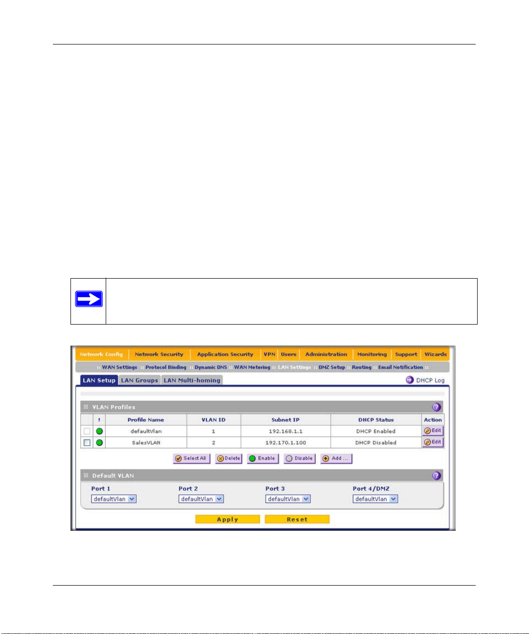
ProSecure Unified Threat Management (UTM) Appliance Reference Manual
LDAP Server
A Lightweight Directory Access Protocol (LDAP) server allows a user to query and modify
directory services that run over TCP/IP. For example, clients can query email addresses, contact
information, and other service information using an LDAP server. For each VLAN, you can
specify an LDAP server and a search base that defines the location in the directory (that is, the
directory tree) from which the LDAP search begins.
Configuring a VLAN Profile
For each VLAN on the UTM, you can configure its profile, port membership, LAN TCP/IP
settings, DHCP options, and DNS server.
To add or edit a VLAN profile:
1. Select Network Config > LAN Settings from the menu. The LAN submenu tabs appear, with
the LAN Setup screen in view (see Figure 4-2, which shows two VLAN profiles as an
example).
Note: For information about how to manage VLANs, see “Managing the UTM’s
Port-Based VLANs” on page 4-2 . The information below describes how to
configure a VLAN profile.
Figure 4-2
4-6 LAN Configuration
v1.0, January 2010
Page 93

ProSecure Unified Threat Management (UTM) Appliance Reference Manual
2. Either select an entry from the VLAN Profiles table by clicking the corresponding Edit table
button or add a new VLAN profile by clicking the Add table button under the VLAN Profiles
table. The Edit VLAN Profile screen displays (see Figure 4-3).
Figure 4-3
LAN Configuration 4-7
v1.0, January 2010
Page 94

ProSecure Unified Threat Management (UTM) Appliance Reference Manual
3. Enter the settings as explained in Table 4-1.
Table 4-1. VLAN Profile Settings
Setting Description (or Subfield and Description)
VLAN Profile
Profile Name Enter a unique name for the VLAN profile.
Note: You can also change the profile name of the default VLAN.
VLAN ID Enter a unique ID number for the VLAN profile. No two VLAN can have the same
VLAN ID number.
Note: You can enter VLAN IDs from 2 to 4093. VLAN ID 1 is reserved for the
default VLAN; VLAN ID 4094 is reserved for the DMZ interface.
Port Membership
Port 1
Port 2
Port 3
Port 4 / DMZ
LAN TCP/IP Setup
IP Address Enter th e IP address of the UTM (the factory default is 192.168.1.1).
Subnet Mask Enter the IP subnet mask. The subnet mask specifies the network number portion
DHCP
Disable DHCP
Server
Enable DHCP
Server
Select one, several, or all port checkboxes to make the port(s) member of this
VLAN.
Note: A port that is defined as a member of a VLAN profile can send and receive
data frames that are tagged with the VLAN ID.
Note: Always make sure that the LAN port IP address and DMZ port IP address
are in different subnets.
Note: If you change the LAN IP address of the VLAN while being connected
through the browser to the VLAN, you will be disconnected. You must then open
a new connection to the new IP address and log in again. For example, if you
change the default IP address 192.168.1.1 to 10.0.0.1, you must now enter
https://10.0.0.1 in your browser to reconnect to the Web Management Interface.
of an IP address. Based on the IP address that you assign, the UTM
automatically calculates the subnet mask. Unless you are implementing
subnetting, use 255.255.255.0 as the subnet mask (computed by the UTM).
If another device on your network is the DHCP server for the VLAN, or if you will
manually configure the network settings of all of your computers, select the
Disable DHCP Server radio button to disable the DHCP server. This is the
default setting.
Select the Enable DHCP Server radio button to enable the UTM to function as a
Dynamic Host Configuration Protocol (DHCP) server, providing TCP/IP
configuration for all computers connected to the VLAN. Enter the following
settings:
Domain Name This is optional. Enter the domain name of the UTM.
4-8 LAN Configuration
v1.0, January 2010
Page 95

ProSecure Unified Threat Management (UTM) Appliance Reference Manual
Table 4-1. VLAN Profile Settings (continued)
Setting Description (or Subfield and Description)
Enable DHCP
Server
(continued)
DHCP Relay Select the DHCP Relay radio button to use the UTM as a DHCP relay agent for a
Enable LDAP
information
Starting IP
Address
Ending IP
Address
Primary DNS
Server
Secondary DNS
Server
WINS Server This is optional. Enter a WINS server IP address to specify
Lease Time Enter a lease time. This specifies the duration for which IP
DHCP server somewhere else on your network. Enter the following setting:
Relay Gateway The IP address of the DHCP server for which the UTM serves
Select the Enable LDAP information checkbox to enable the DHCP server to
provide Lightweight Directory Access Protocol (LDAP) server information. Enter
the settings below.
Note: The LDAP settings that you specify as part of the VLAN profile are used
only for SSL VPN and UTM authentication, but not for Web and e-mail security.
LDAP Server The IP address or name of the LDAP server.
Enter the starting IP address. This address specifies the first
of the contiguous addresses in the IP address pool. Any new
DHCP client joining the LAN is assigned an IP address
between this address and the Ending IP Address. The IP
address 192.168.1.2 is the default start address.
Enter the ending IP address. This address specifies the last
of the contiguous addresses in the IP address pool. Any new
DHCP client joining the LAN is assigned an IP address
between the Starting IP address and this IP address. The IP
address 192.168.1.100 is the default ending address.
Note: The starting and ending DHCP IP addresses should be
in the same “network” as the LAN TCP/IP address of the
UTM (the IP address in LAN TCP/IP section above).
This is optional. If an IP address is specified, the UTM
provides this address as the primary DNS server IP address.
If no address is specified, the UTM uses the VLAN IP
address as the primary DNS server IP address.
This is optional. If an IP address is specified, the UTM
provides this address as the secondary DNS server IP
address.
the Windows NetBios server, if one is present in your
network.
addresses are leased to clients.
as a relay.
LAN Configuration 4-9
v1.0, January 2010
Page 96

ProSecure Unified Threat Management (UTM) Appliance Reference Manual
Table 4-1. VLAN Profile Settings (continued)
Setting Description (or Subfield and Description)
Enable LDAP
information
(continued)
DNS Proxy
Enable DNS Proxy This is optional. Select the Enable DNS Proxy radio button to enable the UTM to
Inter VLAN Routing
Enable Inter VLAN
Routing
Search Base The search objects that specify the location in the directory
tree from which the LDAP search begin. You can specify
multiple search object, separated by commas. The search
objects include:
• cn (for common name)
• ou (for organizational unit)
• o (for organization)
• c (for country)
• dc (for domain)
For example, to search the Netgear.net domain for all last
names of Johnson, you would enter:
cn=Johnson,dc=Netgear,dc=net
port The port number for the LDAP server. The default setting is
zero.
provide a LAN IP address for DNS address name resolution. This setting is
disabled by default.
Note: When you deselect the Enable DNS Proxy radio button, the UTM still
services DNS requests that are sent to its LAN IP address unless you disable
DNS Proxy in the firewall settings (see “Attack Checks” on page 5-27).
This is optional. Select the Enable Inter VLAN Routing radio button to ensure
that traffic is routed only to VLANs for which inter VLAN routing is enabled. This
setting is disabled by default. When the Enable Inter VLAN Routing radio button
is deselected, traffic from this VLAN is not routed to other VLANs, and traffic from
other VLANs is not routed to this VLAN.
4. Click Apply to save your settings.
Note: Once you have completed the LAN setup, all outbound traffic is allowed and
all inbound traffic is discarded except responses to requests from the LAN
side. T o change these default traffic rules, see Chapter 5, “Firewall Protection.”
4-10 LAN Configuration
v1.0, January 2010
Page 97

ProSecure Unified Threat Management (UTM) Appliance Reference Manual
Configuring Multi-Home LAN IPs on the Default VLAN
If you have computers using different IP networks in the LAN, (for example, 172.16.2.0 or
10.0.0.0), you can add aliases to the LAN ports and give computers on those networks access to
the Internet, but you can do so only for the default VLAN. The IP address that is assigned as a
secondary IP address must be unique and must not be assigned to the VLAN.
It is important that you ensure that any secondary LAN addresses are different from the
primary LAN, WAN, and DMZ IP addresses and subnet addresses that are already
configured on the UTM. The following is an example of properly configured IP
addresses on a dual-WAN port model:
WAN1 IP address: 10.0.0.1 with subnet 255.0.0.0
WAN2 IP address: 20.0.0.1 with subnet 255.0.0.0
DMZ IP address: 192.168.10.1 with subnet 255.255.255.0
Primary LAN IP address: 192.168.1.1 with subnet 255.255.255.0
Secondary LAN IP address: 192.168.20.1 with subnet 255.255.255.0
To add a secondary LAN IP address:
1. Select Network Config > LAN Settings from the menu. The LAN Settings submenu tabs
appear, with the LAN Setup screen in view.
2. Click the LAN Multi-homing submenu tab. The LAN Multi-homing screen displays.
Figure 4-4
The Available Secondary LAN IPs table displays the secondary LAN IP addresses added to
the UTM.
LAN Configuration 4-11
v1.0, January 2010
Page 98

ProSecure Unified Threat Management (UTM) Appliance Reference Manual
3. In the Add Secondary LAN IPs section of the screen, enter the following settings:
• IP Address. Enter the secondary address that you want to assign to the LAN ports.
• Subnet Mask. Enter the subnet mask for the secondary IP address.
4. Click the Add table button in the rightmost column to add the secondary IP address to the
Available Secondary LAN IPs table.
Repeat step 3 and step 4 for each secondary IP address that you want to add to the Available
Secondary LAN IPs table.
Note: Secondary IP addres ses cannot be conf igured in the DHCP server. The hosts on the
secondary subnets must be manually configured with the IP addresses, gateway IP
address and DNS server IP addresses.
Managing Groups and Hosts (LAN Groups)
The Known PCs and Devices table on the LAN Groups screen (see Figure 4-5 on page 4-14)
contains a list of all known PCs and network devices that are assigned dynamic IP addresses by the
UTM, or have been discovered by other means. Collectively, these entries make up the Network
Database.
The Network Database is updated by these methods:
• DHCP Client Requests. When the DHCP server is enabled, it accepts and responds to DHCP
client requests from PCs and other network devices. These requests also generate an entry in
the Network Database. This is an advantage of enabling the DHCP Server feature.
• Scanning the Network. The local network is scanned using Address Resolution Protocol
(ARP) requests. The ARP scan detects active devices that are not DHCP clients.
Note: In large networks, scanning the network might generate unwanted traffic.
Note: When the UTM receives a reply to an ARP request, it might not be able to
determine the device name if the software firewall of the device blocks the
name.
• Manual Entry. You can manually enter information about a network device.
4-12 LAN Configuration
v1.0, January 2010
Page 99

ProSecure Unified Threat Management (UTM) Appliance Reference Manual
Some advantages of the Network Database are:
• Generally, you do not need to enter either IP address or MAC addresses. Instead, you can just
select the name of the desired PC or device.
• There is no need to reserve an IP address for a PC in the DHCP server. All IP address
assignments made by the DHCP server are maintained until the PC or device is removed from
the Network Database, either by expiration (inactive for a long time) or by you.
• There is no need to use a fixed IP address on a PCs. Because the IP address allocated by the
DHCP server never changes, you do not need to assign a fixed IP address to a PC to ensure it
always has the same IP address.
• A PC is identified by its MAC address—not its IP address. The Network Database uses the
MAC address to identify each PC or device. Therefore, changing a PC’s IP address does not
affect any restrictions applied to that PC.
• Control over PCs can be assigned to groups and individuals:
– You can assign PCs to groups (see “Managing the Network Database” on this page) and
apply restrictions (outbound rules and inbound rules) to each group (see “Using Rules to
Block or Allow Specific Kinds of Traffic” on page 5-3).
– You can select groups that are allowed access to applications, Web categories, and URLs
that you have blocked for all other users, or the other way around, block access to
applications, W eb categories, and URLs that yo u have allowed access to for all other users
(see “Setting Web Access Exceptions and Scanning Exclusions” on page 6-41).
– If necessary, you can also create firewall rules to apply to a single PC (see “Enabling
Source MAC Filtering” on page 5-42). Because the MAC address is used to identify each
PC, users cannot avoid these restrictions by changing their IP address.
Managing the Network Database
You can view the Network Database, manually add or remove database entries, and edit database
entries.
To view the Network Database:
1. Select Network Config > LAN Settings from the menu. The LAN Settings submenu tabs
appear, with the LAN Setup screen in view.
2. Click the LAN Groups submenu tab. The LAN Groups screen displays (see Figure 4-5 on
page 4-14, which shows some examples in the Known PCs and Devices table).
LAN Configuration 4-13
v1.0, January 2010
Page 100

ProSecure Unified Threat Management (UTM) Appliance Reference Manual
Figure 4-5
The Known PCs and Devices table lists the entries in the Network Database. For each PC or
device, the following fields are displayed:
• Checkbox. Allows you to select the PC or device in the table.
• Name. The name of the PC or device. For computers that do not support the NetBIOS
protocol, the name is displayed as “Unknown” (you can edit the entry manually to add a
meaningful name). If the PC or device was assigned an IP address by the DHCP server,
then the name is appended by an asterisk.
• IP Address. The current IP address of the PC or device. For DHCP clients of the UTM,
this IP address does not change. If a PC or device is assigned a static IP address, you need
to update this entry manually after the IP address on the PC or device has changed.
• MAC Address. The MAC address of the PC or device’s network interface.
• Group. Each PC or device can be assigned to a single LAN group. By default, a PC or
device is assigned to Group 1. You can select a different LAN group from the Group
pull-down menu in the Add Known PCs and Devices section or on the Edit Groups and
Hosts screen.
• Action. The Edit table button that provides access to the Edit Groups and Hosts screen.
4-14 LAN Configuration
v1.0, January 2010
 Loading...