

Netgear GS516TP Installation Manual [zh]

GS516TP Gigabit Smart Switches
Software Administration Manual
350 East Plumeria Drive
San Jose, CA 95134
USA
June 2013
202-11259-01
v1.0

GS516TP Gigabit Smart Switches
No part of this publication may be reproduced, transmitted, transcribed, stored in a retrieval system, or translated
into any language in any form or by any means without the written permission of NETGEAR, Inc.
NETGEAR, the NETGEAR logo, and Connect with Innovation
NETGEAR, Inc. and/or its subsidiaries in the United States and/or other countries. Information is subject to change
without notice. Other brand and product names are registered trademarks or trademarks of their respective
holders. © NETGEAR, Inc. All rights reserved.
re trademarks and/or registered trademarks of
a
Tech nica l Sup port
Thank you for choosing NETGEAR. T o register your product, get the latest product updates, get support online, or
for more information about the topics covered in this manual, visit the Support website at
http://support.netgear.com
Phone (US & Canada only): 1-888-NETGEAR.
Phone (Other Countries): Check the list of phone numbers at
http://support.netgear.com/app/answers/det
ail/a_id/984.
Statement of Conditions
To improve internal design, operational function, and/or reliability, NETGEAR reserves the right to make changes
to the products described in this document without notice. NETGEAR does not assume any liability that may occur
due to the use, or application of, the product(s) or circuit layout(s) described herein.
Revision History
Publication Part Number Version Publish Date Comments
202-11259-01 v1.0 June 2013 First publication
2

Contents
Chapter 1 Getting Started
Chapter 2 Configuring System Information
Getting Started with the NETGEAR Switch. . . . . . . . . . . . . . . . . . . . . . . . 10
Switch Management Interface. . . . . . . . . . . . . . . . . . . . . . . . . . . . . . . . . . 11
Connect the Switch to the Network . . . . . . . . . . . . . . . . . . . . . . . . . . . . . . 12
Discover a Switch in a Network w
Switch Discovery in a Network Without a DHCP Server . . . . . . . . . . . . . . 15
Configure the Network Settings on the Adminis
Access the Management Interface f
Understand the User Interface. . . . . . . . . . . . . . . . . . . . . . . . . . . . . . . . 19
Use SNMP. . . . . . . . . . . . . . . . . . . . . . . . . . . . . . . . . . . . . . . . . . . . . . . 24
Interface Naming Convention . . . . . . . . . . . . . . . . . . . . . . . . . . . . . . . . . . 25
Management . . . . . . . . . . . . . . . . . . . . . . . . . . . . . . . . . . . . . . . . . . . . . . . 27
System Information . . . . . . . . . . . . . . . . .
IP Configuration. . . . . . . . . . . . . . . . . . . . . . . . . . . . . . . . . . . . . . . . . . . 28
IPv6 Network Configuration. . . . . . . . . . . . .
IPv6 Network Neighbors . . . . . . . . . . . . . . .
Time. . . . . . . . . . . . . . . . . . . . . . . . . . . . . . . . . . . . . . . . . . . . . . . . . . . . 31
DNS. . . . . . . . . . . . . . . . . . . . . . . . . . . . . . . . . . . . . . . . . . . . . . . . . . . . 34
Green Ethernet Configuration . . . . . . . . . . . . . . . . . . . . . . . . . . . . . . . . 35
PoE . . . . . . . . . . . . . . . . . . . . . . . . . . . . . . . . . . . . . . . . . . . . . . . . . . . . . . 39
PoE Global Configuration . . . . . . . . . . . . . . . . . . . . . . . . . . . . . . . . . . . 41
PoE Port Configuration . . . . . . . . . . . . . . . . . . . . . . . . . . . . . . . . . . . . . 41
PoE PD Port Status. . . . . . . . . . . . . . . . . . . . . . . . . . . . . . . . . . . . . . . . 42
Timer Global Configuration . . . . . . . . . . . . . . . . . . . . . . . . . . . . . . . . . . 43
SNMP . . . . . . . . . . . . . . . . . . . . . . . . . . . . . . . . . . . . . . . . . . . . . . . . . . . . 44
SNMP v1/v2. . . . . . . . . . . . . . . . . . . . . . . . . . . . . . . . . . . . . . . . . . . . . . 44
Trap Flags . . . . . . . . . . . . . . . . . . . . . . . . . . . . . . . . . . . . . . . . . . . . . . . 45
SNMP Supported MIBs . . . . . . . . . . . . . . . . . . . . . . . . . . . . . . . . . . . . . 46
SNMP v3 User Configuration. . . . . . . . . . . . . . . . . . . . . . . . . . . . . . . . . 46
LLDP . . . . . . . . . . . . . . . . . . . . . . . . . . . . . . . . . . . . . . . . . . . . . . . . . . . . . 47
LLDP Configuration . . . . . . . . . . . . . . . . . . . . . . . . . . . . . . . . . . . . . . . . 47
LLDP Port Settings . . . . . . . . . . . . . . . . . . . . . . . . . . . . . . . . . . . . . . . . 48
LLDP-MED Network Policy . . . . . . . . . . . . . . . . . . . . . . . . . . . . . . . . . . 49
LLDP-MED Port Settings. . . . . . . . . . . . . . . . . . . . . . . . . . . . . . . . . . . . 49
Local Information. . . . . . . . . . . . . . . . . . . . . . . . . . . . . . . . . . . . . . . . . . 50
Neighbors Information . . . . . . . . . . . . . . . . . . . . . . . . . . . . . . . . . . . . . . 51
Services—DHCP Snooping. . . . . . . . . . . . . . . . . . . . . . . . . . . . . . . . . . . . 55
ith a DHCP Server . . . . . . . . . . . . . . . . 13
trative System . . . . . . . . . 17
rom the Web . . . . . . . . . . . . . . . . . . . 19
. . . . . . . . . . . . . . . . . . . . . . . 27
. . . . . . . . . . . . . . . . . . . . . 29
. . . . . . . . . . . . . . . . . . . . . 30
Table of Contents | 3

GS516TP Gigabit Smart Switches
DHCP Snooping Global Configuration . . . . . . . . . . . . . . . . . . . . . . . . . .55
DHCP Snooping Interface Configuration . . . . . . . . . . . . . . . . . . . . . . . .55
DHCP Snooping Binding Configuration . . . . . . . . . . . . . . . . . . . . . . . . .56
DHCP Snooping Persistent Configuration
. . . . . . . . . . . . . . . . . . . . . . . 57
Chapter 3 Configuring Switching Information
Ports. . . . . . . . . . . . . . . . . . . . . . . . . . . . . . . . . . . . . . . . . . . . . . . . . . . . . .59
Global Configuration. . . . . . . . . . . . . . . . . . . . . . . . . . . . . . . . . . . . . . . .59
Port Configuration. . . . . . . . . . . . . . . . . . . . . . . . . . . . . . . . . . . . . . . . . . 59
Link Aggregation Groups . . . . . . . . . . . . . . . . . . . . . . . . . . . . . . . . . . . . . .61
LAG Configuration . . . . . . . . . . . . . . . . . . . . . . . . . . . . . . . . . . . . . . . . .61
LAG Membership . . . . . . . . . . . . . . . . . . . . . . . . . . . . . . . . . . . . . . . . . . 62
LACP Configuration . . . . . . . . . . . . . . . . . . . . . . . . . . . . . . . . . . . . . . . .63
LACP Port Configuration . . . . . . . . . . . . . . . . . . . . . . . . . . . . . . . . . . . .63
VLANs . . . . . . . . . . . . . . . . . . . . . . . . . . . . . . . . . . . . . . . . . . . . . . . . . . . . 64
VLAN Configuration . . . . . . . . . . . . . . . . . . . . . . . . . . . . . . . . . . . . . . . .64
VLAN Membership Configuration. . . . . . . . .
Port VLAN ID Configuration . . . . . . . . . . . . . . . . . . . . . . . . . . . . . . . . . .66
Voice VLAN . . . . . . . . . . . . . . . . . . . . . . . . . . . . . . . . . . . . . . . . . . . . . . . .67
Voice VLAN Properties. . . . . . . . . . . . . . . . . . . . . . . . . . . . . . . . . . . . . .67
Voice VLAN Port Setting . . . . . . . . . . . . . . . . . . . . . . . . . . . . . . . . . . . . 67
Voice VLAN OUI. . . . . . . . . . . . . . . . . . . . . . . . . . . . . . . . . . . . . . . . . . .68
Auto-VoIP Configuration. . . . . . . . . . . . . . . . . . . . . . . . . . . . . . . . . . . . . . . 69
Spanning Tree Protocol . . . . . . . . . . . . . . . . . . . . . . . . . . . . . . . . . . . . . . . 70
STP Configuration . . . . . . . . . . . . . . . . . . . . . . . . . . . . . . . . . . . . . . . . .70
CST Configuration . . . . . . . . . . . . . . . . . . . . . . . . . . . . . . . . . . . . . . . . .72
CST Port Configuration . . . . . . . . . . . . . . . . . . . . . . . . . . . . . . . . . . . . .73
CST Port Status . . . . . . . . . . . . . . . . . . . . . . . . . . . . . . . . . . . . . . . . . . .74
Rapid STP . . . . . . . . . . . . . . . . . . . . . . . . . . . . . . . . . . . . . . . . . . . . . . .75
MST Configuration . . . . . . . . . . . . . . . . . . . . . . . . . . . . . . . . . . . . . . . . .75
MST Port Configuration . . . . . . . . . . . . . . . . . . . . . . . . . . . . . . . . . . . . .76
Multicast. . . . . . . . . . . . . . . . . . . . . . . . . . . . . . . . . . . . . . . . . . . . . . . . . . . 79
MFDB . . . . . . . . . . . . . . . . . . . . . . . . . . . . . . . . . . . . . . . . . . . . . . . . . . .79
Auto-Video Configuration . . . . . . . . . . . . . . . . . . . . . . . . . . . . . . . . . . . .80
IGMP Snooping . . . . . . . . . . . . . . . . . . . . . . . . . . . . . . . . . . . . . . . . . . .81
IGMP Snooping Querier. . . . . . . . . . . . . . . . . . . . . . . . . . . . . . . . . . . . . 84
MLD Snooping . . . . . . . . . . . . . . . . . . . . . . . . . . . . . . . . . . . . . . . . . . . .86
Static Multicast Address. . . . . . . . . . . . . . . . . . . . . . . . . . . . . . . . . . . . . 88
Forwarding Database. . . . . . . . .
Address Table . . . . . . . . . . . . . . . . . . . . . . . . . . . . . . . . . . . . . . . . . . . . 91
Dynamic Address Configuration. . . . . . . . . . . . . . . . . . . . . . . . . . . . . . .92
Static MAC Address . . . . . . . . . . . . . . . . . . . . . . . . . . . . . . . . . . . . . . . . 92
. . . . . . . . . . . . . . . . . . . . . . . . . . . . . . . .91
. . . . . . . . . . . . . . . . . . . . .65
Chapter 4 Configuring Routing
Configure IP Settings . . . . . . . . . . . . . . . . . . . . . . . . . . . . . . . . . . . . . . . . .94
Configure VLAN Routing . . . . . . . . . . . . . . . . . . . . . . . . . . . . . . . . . . . . . .95
VLAN Routing Wizard. . . . . . . . . . . . . . . . . . . . . . . . . . . . . . . . . . . . . . . 95
4

GS516TP Gigabit Smart Switches
Configure VLAN Routing . . . . . . . . . . . . . . . . . . . . . . . . . . . . . . . . . . . .96
Configure and View Routes . . . . . . . . . . . . . . . . . . . . . . . . . . . . . . . . . . . .97
Configure ARP . . . . . . . . . . . . . . . . . . . . . . . . . . . . . . . . . . . . . . . . . . . . . .99
ARP Entry Configuration. . . . . . . . . . . . . . . . . . . . . . . . . . . . . . . . . . . .100
Chapter 5 Configure Quality of Service
Class of Service . . . . . . . . . . . . . . . . . . . . . . . . . . . . . . . . . . . . . . . . . . . .104
Basic CoS Configuration. . . . . . . . . . . . . . . . . . . . . . . . . . . . . . . . . . . .104
CoS Interface Configuration . . . . . . . . . . . . . . . . . . . . . . . . . . . . . . . . .105
Queue Configuration. . . . . . . . . . . . . . . . . . . . . . . . . . . . . . . . . . . . . . .105
802.1p to Queue Mapping . . . . . . . . . . . . . . . . . . . . . . . . . . . . . . . . . .106
DSCP to Queue Mapping. . . . . . . . . . . . . . . . . . . . . . . . . . . . . . . . . . .107
Differentiated Services . . . . . . . . . . . . . . . . . . . . . . . . . . . . . . . . . . . . . . .108
Defining DiffServ. . . . . . . . . . . . . . . . . . . . . . . . . . . . . . . . . . . . . . . . . .108
Diffserv Configuration. . . . . . . . . . . . . . . . . . . . . . . . . . . . . . . . . . . . . .109
DSCP Violate Action Mapping . . . . . . . . . . . . . . . . . . . . . . . . . . . . . . .109
Class Configuration . . . . . . . . . . . . . . . . . . . . . . . . . . . . . . . . . . . . . . .110
IPv6 Class Configuration . . . . . . . . . . . . . . . . . . . . . . . . . . . . . . . . . . .111
Policy Configuration . . . . . . . . . . . . . . . . . . . . . . . . . . . . . . . . . . . . . . .112
Service Configuration . . . . . . . . . . . . . . . . . . . . . . . . . . . . . . . . . . . . . .114
Service Statistics . . . . . . . . . . . . . . . . . . . . . . . . . . . . . . . . . . . . . . . . .114
Chapter 6 Managing Device Security
Management Security Settings. . . . . . . . . . . . . . . . . . . . . . . . . . . . . . . . .117
Change Password . . . . . . . . . . . . . . . . . . . . . . . . . . . . . . . . . . . . . . . .117
Configure RADIUS Settings . . . . . . . . . . . . . . . . . . . . . . . . . . . . . . . . .117
Configure TACACS+ . . . . . . . . . . . . . . . . . . . . . . . . . . . . . . . . . . . . . .120
Authentication List Configuration . . . . . . . . . . . . . . . . . . . . . . . . . . . . .121
Configure Management Access . . . . . . . . . . . . . . . . . . . . . . . . . . . . . . . .124
HTTP Configuration . . . . . . . . . . . . . . . . . . . . . . . . . . . . . . . . . . . . . . .124
Secure HTTP Configuration . . . . . . . . . . . . . . . . . . . . . . . . . . . . . . . . .124
Certificate Management . . . . . . . . . . . . . . . . . . . . . . . . . . . . . . . . . . . .125
Access Control . . . . . . . . . . . . . . . . . . . . . . . . . . . . . . . . . . . . . . . . . . .125
Port Authentication. . . . . . . . . . . . . . . . . . . . . . . . . . . . . . . . . . . . . . . . . .127
802.1x Configuration. . . . . . . . . . . . . . . . . . . . . . . . . . . . . . . . . . . . . . .127
Port Authentication . . . . . . . . . . . . . . . . . . . . . . . . . . . . . . . . . . . . . . . .128
Port Summary. . . . . . . . . . . . . . . . . . . . . . . . . . . . . . . . . . . . . . . . . . . .130
Traffic Control. . . . . . . . . . . . . . . . . . . . . . . . . . . . . . . . . . . . . . . . . . . . . .132
Storm Control . . . . . . . . . . . . . . . . . . . . . . . . . . . . . . . . . . . . . . . . . . . .132
Port Security Interface Configuration . . . . . . . . . . . . . . . . . . . . . . . . . .133
Security MAC Address . . . . . . . . . . . . . . . . . . . . . . . . . . . . . . . . . . . . .133
Protected Ports. . . . . . . . . . . . . . . . . . . . . . . . . . . . . . . . . . . . . . . . . . .134
Configure Access Control Lists . . . . . . . . . . . . . . . . . . . . . . . . . . . . . . . .135
ACL Wizard. . . . . . . . . . . . . . . . . . . . . . . . . . . . . . . . . . . . . . . . . . . . . .135
MAC ACL . . . . . . . . . . . . . . . . . . . . . . . . . . . . . . . . . . . . . . . . . . . . . . .138
MAC Rules . . . . . . . . . . . . . . . . . . . . . . . . . . . . . . . . . . . . . . . . . . . . . .138
MAC Binding Configuration . . . . . . . . . . . . . . . . . . . . . . . . . . . . . . . . .139
5

GS516TP Gigabit Smart Switches
MAC Binding Table. . . . . . . . . . . . . . . . . . . . . . . . . . . . . . . . . . . . . . . .140
IP ACL . . . . . . . . . . . . . . . . . . . . . . . . . . . . . . . . . . . . . . . . . . . . . . . . .141
IP Rules . . . . . . . . . . . . . . . . . . . . . . . . . . . . . . . . . . . . . . . . . . . . . . . . 141
IP Extended Rules . . . . . . . . . . . . . . . . .
IPv6 ACL . . . . . . . . . . . . . . . . . . . . . . . . . . . . . . . . . . . . . . . . . . . . . . .144
IPv6 Rules . . . . . . . . . . . . . . . . . . . . . . . . . . . . . . . . . . . . . . . . . . . . . .145
IP Binding Configuration. . . . . . . . . . . . . . . . . . . . . . . . . . . . . . . . . . . . 146
IP Binding Table. . . . . . . . . . . . . . . . . . . . . . . . . . . . . . . . . . . . . . . . . .147
. . . . . . . . . . . . . . . . . . . . . . .142
Chapter 7 Monitoring the System
Ports. . . . . . . . . . . . . . . . . . . . . . . . . . . . . . . . . . . . . . . . . . . . . . . . . . . . .149
Switch Statistics . . . . . . . . . . . . . . . . . . . . . . . . . . . . . . . . . . . . . . . . . . 149
Port Statistics . . . . . . . . . . . . . . . . . . . . . . . . . . . . . . . . . . . . . . . . . . . . 150
Port Detailed Statistics . . . . . . . . . . . . . . . . . . . . . . . . . . . . . . . . . . . . . 151
EAP Statistics. . . . . . . . . . . . . . . . . . . . . . . . . . . . . . . . . . . . . . . . . . . .154
Cable Test . . . . . . . . . . . . . . . . . . . . . . . . . . . . . . . . . . . . . . . . . . . . . .155
Logs . . . . . . . . . . . . . . . . . . . . . . . . . . . . . . . . . . . . . . . . . . . . . . . . . . . . .157
Buffered Logs. . . . . . . . . . . . . . . . . . . . . . . . . . . . . . . . . . . . . . . . . . . .157
Server Log . . . . . . . . . . . . . . . . . . . . . . . . . . . . . . . . . . . . . . . . . . . . . .158
Trap Logs . . . . . . . . . . . . . . . . . . . . . . . . . . . . . . . . . . . . . . . . . . . . . . .159
Mirroring. . . . . . . . . . . . . . . . . . . . . . . . . . . . . . . . . . . . . . . . . . . . . . . . . . 160
System Resources Utilization. . . . . . . . . . . . . . . . . . . . . . . . . . . . . . . . . .161
Chapter 8 Maintenance
Reset . . . . . . . . . . . . . . . . . . . . . . . . . . . . . . . . . . . . . . . . . . . . . . . . . . . .163
Device Reboot . . . . . . . . . . . . . . . . . . . . . . . . . . . . . . . . . . . . . . . . . . .163
Factory Default. . . . . . . . . . . . . . . . . . . . . . . . . . . . . . . . . . . . . . . . . . .163
Upload a File from the Switch . . . . . . . . . . . . . . . . . . . . . . . . . . . . . . . . .164
TFTP File Upload . . . . . . . . . . . . . . . . . . . . . . . . . . . . . . . . . . . . . . . . .164
HTTP File Upload. . . . . . . . . . . . . . . . . . . . . . . . . . . . . . . . . . . . . . . . .165
Download a File to the Switch . . . . . . . . . . . . . . . . . . . . . . . . . . . . . . . . .166
TFTP File Download. . . . . . . . . . . . . . . . . . . . . . . . . . . . . . . . . . . . . . .166
HTTP File Download . . . . . . . . . . . . . . . . . . . . . . . . . . . . . . . . . . . . . . 167
File Management . . . . . . . . . . . . . . . . . . . . . . . . . . . . . . . . . . . . . . . . . . . 169
Dual Image Configuration. . . . . . . . . . . . . . . . . . . . . . . . . . . . . . . . . . . 169
Dual Image Status . . . . . . . . . . . . . . . . . . . . . . . . . . . . . . . . . . . . . . . .169
Troubleshooting . . . . . . . . . . . . . . . . . . . . . . . . . . . . . . . . . . . . . . . . . . . .171
Ping . . . . . . . . . . . . . . . . . . . . . . . . . . . . . . . . . . . . . . . . . . . . . . . . . . .171
Ping IPv6 . . . . . . . . . . . . . . . . . . . . . . . . . . . . . . . . . . . . . . . . . . . . . . .172
Traceroute . . . . . . . . . . . . . . . . . . . . . . . . . . . . . . . . . . . . . . . . . . . . . .172
Remote Diagnostics . . . . . . . . . . . . . . . . . . . . . . . . . . . . . . . . . . . . . . . 173
Chapter 9 Help
Online Help. . . . . . . . . . . . . . . . . . . . . . . . . . . . . . . . . . . . . . . . . . . . . . . .175
Support. . . . . . . . . . . . . . . . . . . . . . . . . . . . . . . . . . . . . . . . . . . . . . . . . 175
User Guide . . . . . . . . . . . . . . . . . . . . . . . . . . . . . . . . . . . . . . . . . . . . . .175
6

GS516TP Gigabit Smart Switches
Registration . . . . . . . . . . . . . . . . . . . . . . . . . . . . . . . . . . . . . . . . . . . . . . .176
Switch Features and Defaults. . . . . . . . . . . . . . . . . . . . . . . . . . . . . . . . . .179
Virtual Local Area Networks (VLANs). . . . . . . . . . . . . . . . . . . . . . . . . . . .183
Sample VLAN Configuration. . . . . . . . . . . . . . . . . . . . . . . . . . . . . . . . .184
Access Control Lists (ACLs). . . . . . . . . . . . . . . . . . . . . . . . . . . . . . . . . . .185
Sample MAC ACL Configuration . . . . . . . . . . . . . . . . . . . . . . . . . . . . .185
Sample Standard IP ACL Configuration. . . . . . . . . . . . . . . . . . . . . . . .186
Differentiated Services (DiffServ) . . . . . . . . . . . . . . . . . . . . . . . . . . . . . . .188
Class. . . . . . . . . . . . . . . . . . . . . . . . . . . . . . . . . . . . . . . . . . . . . . . . . . .188
DiffServ Traffic Classes . . . . . . . . . . . . . . . . . . . . . . . . . . . . . . . . . . . .189
Create Policies . . . . . . . . . . . . . . . . . . . . . . . . . . . . . . . . . . . . . . . . . . .189
Sample DiffServ Configuration . . . . . . . . . . . . . . . . . . . . . . . . . . . . . . .190
802.1x. . . . . . . . . . . . . . . . . . . . . . . . . . . . . . . . . . . . . . . . . . . . . . . . . . . .193
Sample 802.1x Configuration . . . . . . . . . . . . . . . . . . . . . . . . . . . . . . . .194
MSTP . . . . . . . . . . . . . . . . . . . . . . . . . . . . . . . . . . . . . . . . . . . . . . . . . . . .196
Sample MSTP Configuration . . . . . . . . . . . . . . . . . . . . . . . . . . . . . . . .197
Configure VLAN Routing with Static Route . . . . . . . . . . . . . . . . . . . . . . .200
VLAN Routing Overview. . . . . . . . . . . . . . . . . . . . . . . . . . . . . . . . . . . .200
Sample VLAN Routing Configuration . . . . . . . . . . . . . . . . . . . . . . . . . .200
7

GS516TP Gigabit Smart Switches
8

1. Getting Started
This manual describes how to configure and operate the GS516TP Gigabit Smart Switches by
using the web-based graphical user interface (GUI). This manual describes the software
configuration procedures and explains the options available within those procedures. This switch
is referred to as the NETGEAR switch throughout this document.
1
9

GS516TP Gigabit Smart Switches
Getting Started with the NETGEAR Switch
This chapter provides an overview of starting your NETGEAR switch and accessing the user
interface. It also describes some actions that can be performed in the Smart Control Center
(SCC) application, which can be downloaded to your computer.
This guide does not document the SCC application. Full document
http://docs.netgear.com/scc/enu/202-10685-01/index.htm.
This chapter contains the following sections:
• Switch Management Interface
• Connect the Switch to the Network
• Discover a Switch in a Network with a DHCP Server
• Switch Discovery in a Network Without a DHCP Server
• Configure the Network Settings on the Administrative System
• Access the Management Interface from the Web
• Interface Naming Convention
ation for SCC is found at
10

GS516TP Gigabit Smart Switches
Switch Management Interface
The NETGEAR switch contains an embedded web server and management software for
managing and monitoring switch functions. The switch functions as a simple switch without
the management software. However, you can use the management software to configure
more advanced features that can improve switch efficiency and overall network performance.
Web-based management lets you monitor, configure, and control your switch remot ely using
a
standard web browser instead of using expensive and complicated SNMP software
products. From your web browser, you can monitor the performance of your switch and
optimize its configuration for your network. You can configure all switch features, such as
VLANs, QoS, and ACLs, by using the web-based management interface.
NETGEAR provides the Smart Control Center utility with
under Windows XP, Windows 2003, Windows 2008 or Windows 7 (32 bit and 64 bit) and
p
rovides a front end that discovers the switches on your network segment (L2 broadcast
domain). When you power up your switch for the first time, use the Smart Control Center to
discover the switch and view the network information that was automatically assigned to the
switch by a DHCP server; or, if no DHCP server is present on the network, use the Smart
Control Center to discover the switch and assign static network information.
this product. This program runs
11

GS516TP Gigabit Smart Switches
Connect the Switch to the Network
To enable remote management of the switch through a web browser or SNMP, you must
connect the switch to the network and configure it with network information (an IP address,
subnet mask, and default gateway). The switch has a default IP address of 192.168.1.1 and a
default subnet mask of 255.255.255.0.
To change the default network information about the switch, use one of the following three
hods:
met
• Dynamic
connect the switch to a network with a DHCP server, the switch obtains its network
information automatically. You can use the Smart Control Center to discover the
automatically assigned network information. For detailed information, see Switch
Discovery in a Network Without a DHCP Server .
• S
tatic assignment through the Smart Control Center. If you connect the switch to a
network that does not have a DHCP server, you can use the Smart Control Center to
assign a static IP address, subnet mask, and default gateway. For detailed information,
see Switch Discovery in a Network Without a DHCP Server .
tatic assignment by connecting from a local host. If you do not want to use the
• S
Smart Control Center to assign a static address, you can connect to the switch from a
host (administrative system) in the 192.168.0.0/24 network and change the settings by
using the web-based management interface on the switch. For information about how to
set the IP address on the administrative system so it is in the same subnet as the default
IP address of the switch, see Configure the Network Settings on the Administrative
System .
assignment through DHCP. DHCP is enabled by default on the switch. If you
12
GS516TP Gigabit Smart Switches
Discover a Switch in a Network with a DHCP Server
This section describes how to set up your switch in a network that has a DHCP server. The
DHCP client on the switch is enabled by default. When you connect it to your network, the
DHCP server automatically assigns an IP address to your switch. To discover the IP address
automatically assigned to the switch, use the Smart Control Center.
To install the switch in a network with a DHCP server, use the following steps:
1. Connect the switch to a network with a DHCP server.
2. Power on the switch
3. Install the Smart Control Center on your computer.
4. Start the Smart Control Center.
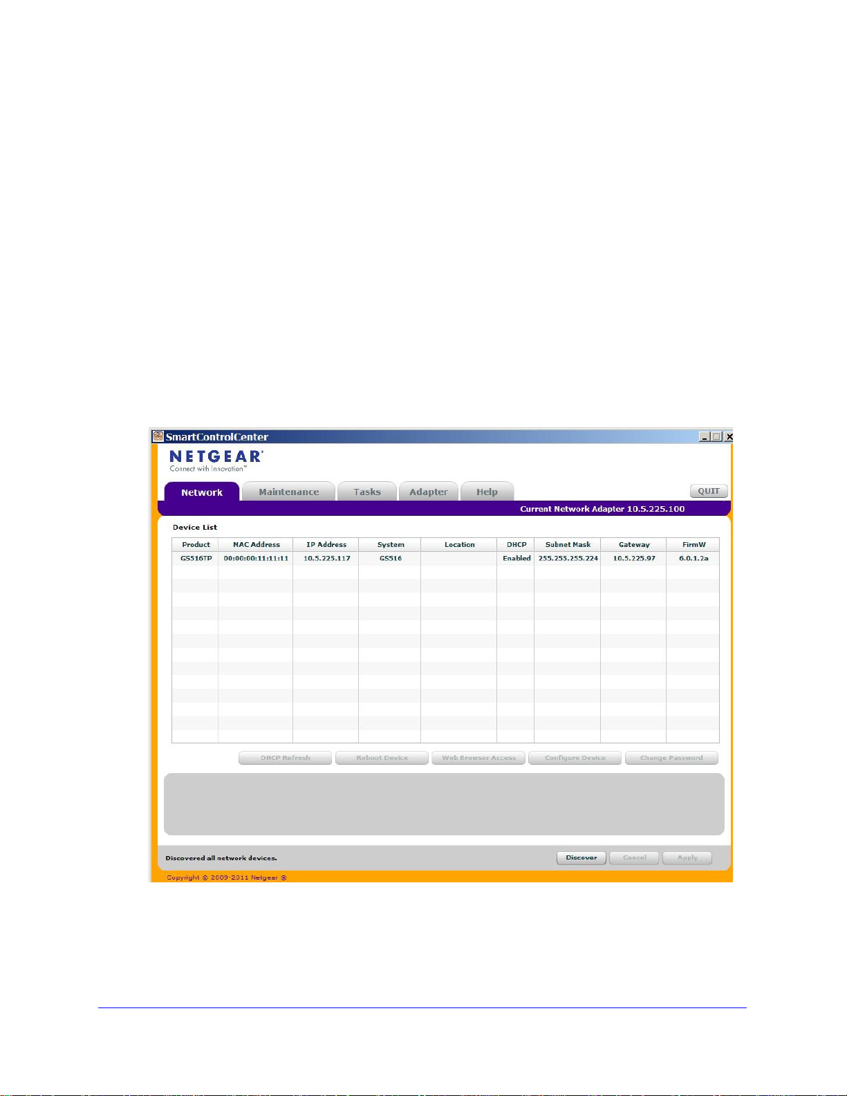
5. Click Discover
A screen similar to the one shown below is displayed.
by connecting its power cord.
for the Smart Control Center to find your switch.
6. Make a note of the displayed IP address assigned by the DHCP server.
You need this value to access the switch directly from a web browser (wit
Smart Control Center).
13
hout using the

GS516TP Gigabit Smart Switches
7. Select your switch by clicking the line that displays the switch, then click the
Web Browser Access butt
on.
The Smart Control Center displays a login window.
The default password is p
assword. Use this screen to manage your switch. For more
information, see Access the Management Interface from the Web .
14
GS516TP Gigabit Smart Switches
Switch Discovery in a Network Without a DHCP Server
This section describes how to use the Smart Control Center to set up your switch in a
network without a DHCP server. If your network has no DHCP service, you must assign a
static IP address to your switch. You can assign it a static IP address, even if your network
has DHCP service.
To assign a static IP address:
1. Connect the switch to your existing network.
2. Power on the switch
3. Install the Smart Control Center on your computer.
4. Start the Smart Control Center.
5. Click Discover
The utility broadcasts Layer 2 discovery packets within the broadcast domain to discover
the swi
tch.
by connecting its power cord.
for the Smart Control Center to find your NETGEAR switch.
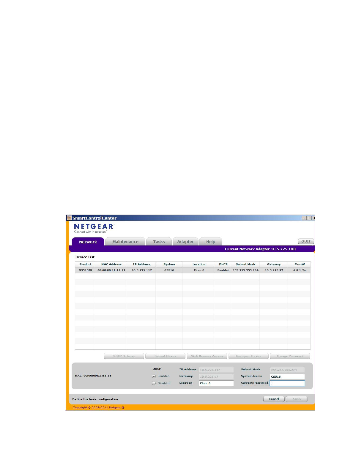
6. Select the
The screen expands to display more fields at the bottom of the screen.
.
switch, then
click Configure Device.
15

GS516TP Gigabit Smart Switches
7. Select the Disabled radio button to disable DHCP.
8. Enter the
static switch IP address, gateway IP address, and subnet mask for the switch and
type your password.
Tip: Y
ou must enter the current password every time you use the Smart
Control Center to update the switch setting. The default password is
password.
9. Click APPL
Y to configure the switch with the network settings.
Ensure that your computer and the switch are in the same subnet. Make a note of these
set
tings for later use.
16
GS516TP Gigabit Smart Switches
WARNING:
Configure the Network Settings on the Administrative System
If you do not use the Smart Control Center to configure the switch network information, you
can connect directly to the switch from the administrative system installed on your computer.
The IP address of the administrative system must be in the same subnet as the default IP
address on the switch. For most networks, this means you must change the IP address of the
administrative system to be on the same subnet as the default IP address of the switch
(192.168.1.1).
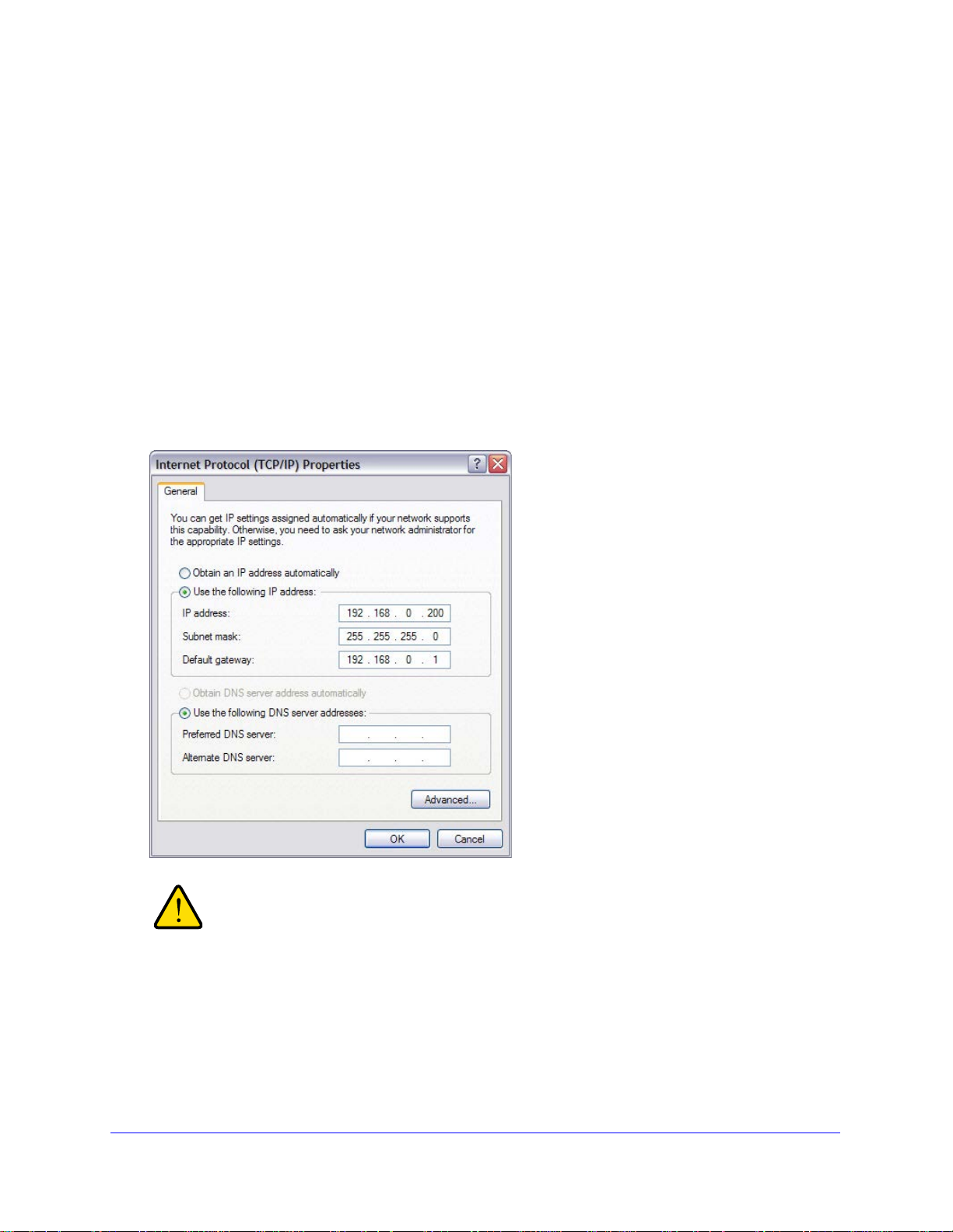
To change the IP address on an administrative system running a Windows operating system,
open th
connection, as shown in the following screen. You need Windows Administrator privileges to
change these settings.
e Internet Protocol (TCP/IP) Properties screen that you access from each local area
When you change the IP address of your administrative system,
connection to the rest of the network is lost. Be sure to write down
your current network address settings before you change them.
To modify the network settings on your administrative system:
1. On your computer
, access the Windows operating system TCP/IP Properties screen.
17

GS516TP Gigabit Smart Switches
2. Set the IP address of the administrative system to an address in the 192.168.0.0 network,
such as 192.168.0.200.
The IP address must be different from the switch’s address but within the same subnet.
3. Click OK.
To configure a static address on the switch:
1. Use a straig
ht-through cable to connect the Ethernet port on the administrative system
directly to any port on the NETGEAR switch.
2. Open a web bro
wser on your computer and connect to the management interface. For more
information, see Access the Management Interface from the Web .
3. Change the network settin
gs on the switch to match the settings on your network. For more
information, see IP Configuration ).
4. Return
the network configuration on your administrative system to the original settings.
18

GS516TP Gigabit Smart Switches
Access the Management Interface from the Web
To access the switch management interface, use one of the following methods:
• F
rom the Smart Control Center, select the switch and click Web Browser Access. For
more information, see the documentation for this application at
http://docs.netgear.com/scc/enu/202-10685-01/index.htm.
• Open
You must be able to ping the IP address of the NETGEAR switch management interface from
your a
Center to set up the IP address and subnet mask, either with or without a DHCP server, use
that IP address in the address field of your web browser. If you did not change the IP address
of the switch from the default value, enter 192.168.0.239 into the address field.
a web browser and enter the IP address of the switch in the address field.
dministrative system for web access to be available. If you used the Smart Control
Clicking Web Browser Access on the Smart Control Center o
from your web browser displays the Login screen.
r accessing the switch directly
Understand the User Interface
To access the switch by using a web browser, the browser must meet the following software
requirements:
• I
nternet Explorer version 7 or later
• F
irefox version 4 or later
To log on to the web interface:
1. Open
2. The factory
a web browser and enter the IP address of the switch in the web browser address
field.
default password is password. Type the password in the field on the Login
screen and click Login. Passwords are case-sensitive.
19
GS516TP Gigabit Smart Switches
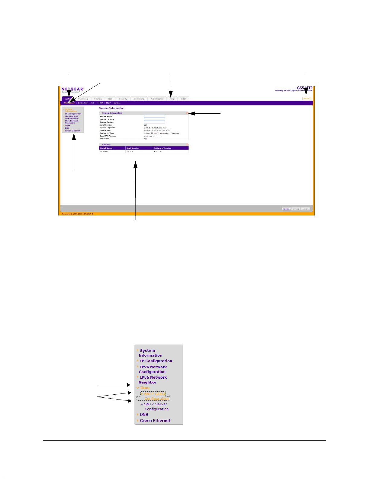
Configuration status a nd options
Navigation tab
Configuration menus
Logout button
Help link
Help
screen
Screen menu
Link
Submenu
Links
3. After the system authenticates you, the System Information screen displays.
Figure 1. Configuration Status and Options
Navigation Tabs, Configuration Menus, and Screen Menu
The navigation tabs along the top of the web interface give you quick access to the various
switch functions. The tabs are always available and remain constant, regardless of which
feature you configure.
When you select a tab, the features for that tab appear as menus directly under the t abs. The
menus in the
The configuration screens for each feature are available as
menu on the left side of the screen.
Some items in the menu expand to reveal multiple submenu links,
blue bar change according to the navigation tab that is selected.
submenu links in the
as shown
in the following:
screen
20

GS516TP Gigabit Smart Switches
When you click a menu item that includes multiple configuration screens, the item becomes
preceded by a down arrow symbol and expands to display the additional submenu links.
Configuration and Status Options
The area directly below the feature links and to the right of the links displays the configuration
information or status for the screen you select. On screens that contain configuration option s,
you can enter information into fields or select options from drop-down lists.
Each screen contains access to the HTML-based
help that explains the fields and
configuration options for the screen. Each screen also contains command buttons.
The following table shows the command buttons that are used throughout the screens in the
web inte
Table 1. Command Buttons
Button Function
ADD Places the new item configured in the heading row of a table.
APPLY Sends the updated configuration to the switch. Configuration changes take effect
CANCEL Resets the dat a on the screen to the latest value
DELETE Removes the selected item.
REFRESH Reloads the screen with the latest in
LOGOUT Ends the session.
rface.
immediately.
of the switch.
formation from the device.
Device View
The Device View is a Java applet that displays the ports on the switch. This graphic provides
an alternate way to navigate to configuration and monitoring options. The graphic also
provides information about device ports, current configuration and status, table information,
and feature components.
The Device View is available by selecting System > Devic
e View .
Depending upon the status of the port, the LED of the port st atus lights. Green indicates that
the port
is enabled. Red indicates that an error occurred on the port and the link is disabled.
The LED of the port speed light in either green or yellow.
• A green LED indicates operational ports at the link speed of 1000 Mbps.
• A yellow LED indicate
s operational ports at the link speed of 10/100 Mbps.
The system LEDs are on the left side of the front panel.
21

Power/Status LED
GS516TP Gigabit Smart Switches
The device supports ports that receive power (p
See PoE Global Configuration
The device supports the following power LEDs.
• The Power
LED is a bicolor LED that serves as an indicator of power and diagnostic
status:
• Off.
• Solid green.
Indicates that power is disconnected.
Indicates that the power is supplied to the switch from the internal power
supply and is operating normally.
• Blinking yellow .Indicate
• The PD LEDs
(two LEDs for ports 15 and 16) describe the state of the ports supplying
s that the system is in the boot-up stage.
power:
• Off.
• S
• S
• The
Indicates that no PSE device is connected to ports 15 or 16.
teady Green. Indicates that AT PSE is connected to ports 15 or 16.
teady Yellow. Indicates that AF PSE is connected to ports 15 or 16.
PoE status LEDs (eight LEDs for ports 1-8) describes the st ate of the ports receiving
power:
• Off.
• Solid green. Indicate
Indicates that no PD device is connected (i.e. no PoE consumption).
s that a PD device has been inserted, and the power status is
OK.
• Solid yellow
. PD Indicates that a PD device has been inserted, but a failure occurred
This means that either PSE cannot deliver power due to a PD error or the power
requested exceeds the power budget.
orts 1-8) and supply power (ports 15, 16).
FAN Status LED
FAN status is indicated as follows:
• A solid yellow LED indicat
• No lit LED indicat
es that the fan is operating normally.
es that the fan is faulty.
Max PoE LED
The Max PoE LED indicates the following:
• A solid yellow LED indicat
• A blinking yello
w LED indicates that the PoE Max LED was lit within the previous 2
es that less than seven watts of PoE power are available.
minutes.
• No lit LED indicat
es that at least seven watts of PoE power are available.
22

GS516TP Gigabit Smart Switches
The following image shows the device view of the NETGEAR switch.
Figure 2. Ports and LEDs on the Switching Devices
Click the port you want to view or configure to see a menu that displays statistics and
configuration options. Click the menu option to access the screen that contains the
configuration or monitoring options.
Figure 3. Device View
If you right-click the graphic, the main menu displays.
Figure 4. Device View Drop Down Menus
Help Access
Every screen contains a link to the online help , which contains information to help
configure and manage the switch. The online help screens are context-sensitive
example, if the IP Addressing screen is open, the help topic for that screen displays if you
click Help. Figure 1, Configuration Status and Options shows the location of the Help link on
the web interface.
. For
23

GS516TP Gigabit Smart Switches
User-Defined Fields
User-defined fields can contain 1 to 159 characters, unless otherwise noted on the
configuration screen. All characters can be used except for the following (unless specifically
noted in for that feature):
\ <
/ >|
* |
?
Use SNMP
The switch software supports the configuration of SNMP groups and users that can manage
traps that the SNMP agent generates.
The switch uses both standard public MIBs for sta
ndard functionality and private MIBs that
support more switch functionality. All private MIBs begin with a hyphen (-) prefix. The main
object for interface configuration is in -SWITCHING-MIB, which is a private MIB. Some
interface configurations also involve objects in the public MIB, IF-MIB.
SNMP is enabled by default. The System Information screen, which displays after a
successf
ul login, displays the information you need to configure an SNMP manager to access
the switch.
Any user can connect to the switch using the SNMPv3 protocol. However, for authentication
and encryption, the
switch only supports a single user called admin, which is the only profile
that can be created or modified.
To configure authentication and encryption settings for the SNMPv3 admin profile by
using the web interface:
t
1. Select the Sys
em > SNMP > SNMPv3 > User Configuration screen.
2. To enable authentication, select one of MD5 and SHA authentication protocol options.
3. To enable encryption:
a. Select
DES as the encrypt
ion protocol.
b. In the Encryption Key field, enter an encryption code of eight or more alphanumeric
racters.
cha
4. Click APPLY.
To access configuration information for SNMPv1 or SNMPv2:
1. Select System > SNMP > SNMPv1/v2
2. Follow the link to the screen that contains the information to configure.
See
SNMP for more information.
24

GS516TP Gigabit Smart Switches
Interface Naming Convention
The switch supports physical and logical interfaces. Interfaces are identified by their type and
the interface number. The switch support the following ports:
• Port
s 1–8. PoE (Power
over Ethernet) Power Source Equipment (PSE) ports providing
up to 15.4 W power
• Ports 9–14. 10/100
• Ports 15–16. PD
/1000 Mbps switching ports
ports receiving power from power devices. These ports can receive AT
power, AF power or no power.
For further information about PoE ports, see PoE
The number of the port is identified on the front panel. You can configure the logical
interfac
es by using the software. The following table describes the naming convention for all
interfaces available on the switch.
Table 2. Naming Convention
Interface Description Example
Physical The physical ports include Gigabit ports and are numbered
Link aggregation group (LAG) LAG interfaces are logical interfaces that are used only for
CPU Management Interface This is the internal switch interface responsible for the
for Switch Interfaces
sequentially starting from 1.
bridging
switch base MAC address. This interface is not
configurable and is always listed in the MAC Address
Table.
functions.
g1, g2, g3
l1, l2, l3
c1
25

2. Configuring System Information
Use the features in the System tab to define the switch’s relationship to its environment. The
System tab contains links to screens described in the following sections:
• Management
• PoE
• SNMP
• LLDP
• Services—DHCP Snooping
2
26

GS516TP Gigabit Smart Switches
Management
This section describes how to display the switch status and specify some basic switch
information, such as the management interface IP address, system clock settings, and DNS
information. From the Management menu, you can access screens described in the following
sections:
• System Information
• IP Configuration
• IPv6 Network Configuration
• IPv6 Network Neighbors
• Time
• DNS
• Green Ethernet Configuration
System Information
After a successful login, the System Information screen displays. Use this screen to configure
and view general device information.
To define system information:
1. Select System > Ma
2. Defin
e the following fields:
• System Name. Enter th
nagement > System Information.
e name you want to use to identify this switch. You can use
up to 160 alphanumeric characters. The factory default is blank.
• Sys
tem Location. Enter the location of this switch. You can use up to 160
alphanumeric characters. The factory default is blank.
• Sys
tem Contact. Enter the contact person for this switch. You can use up to 160
alphanumeric characters. The factory default is blank.
3. Click AP
PLY to apply the changes to the system.
The following table describes the status information displayed in the System screen.
Table 1. System Status Information
Field Description
Serial Number The serial number of the switch.
System Object ID The base object ID for the switch's enterprise MIB.
Date & Time The current date and time.
System Up Time Displays the number of days, hours, and
restart.
27
minutes since the last system

GS516TP Gigabit Smart Switches
Field Description
Base MAC Address Universally assigned network address.
Fan Status The status of fan operation.
Model Name The model name of the switch.
Boot Version The boot code version of the switch.
Software Version
The software version of the switch.
IP Configuration
Use the IP Configuration screen to configure network information for the management
interface, which is the logical interface used for in-band connectivity with the switch through
any of the switch's front-panel ports. The configuration parameters associated with the
switch's network interface do not affect the configuration of the front panel ports through
which traffic is switched or routed.
To configure the network information for the management interface:
1. Select System > Mana
2. Select t
he appropriate radio button to determine how to configure the network information for
the switch management interface:
• Dynamic IP Address (DHCP).
through a DHCP server.
• Dynamic
IP Address (BOOTP). Specifies that the switch must obt ain the IP address
through a BootP server.
• S
tatic IP Address. Specifies that the IP address, subnet mask, and default gateway
must be manually configured. Enter this information in the fields below this radio
button.
gement > IP Configuration.
Specifies that the switch must obtain the IP address
you selected the Static IP Address option, configure the following network information:
3. If
• IP Address. T
he IP address of the network interface. The factory default value is
192.168.0.239. Each part of the IP address must start with a number o ther than 0. For
example, IP addresses 001.100.192.6 and 192.001.10.3 are not valid.
• Subnet Mask.
The IP subnet mask for the interface. The factory default value is
255.255.255.0.
• Default Gateway. The
4. S
pecify the VLAN ID for the management VLAN.
default gateway for the IP interface.
The management VLAN is used to establish an IP connection to the switch from a
workst
ation that is connected to a port in the same VLAN. If not specified, the active
management VLAN ID is 1 (default), which allows an IP connection to be established
through any port.
When the management VLAN is set to a different value, an IP connection can be made
only thro
ugh a port that is part of the management VLAN. It is also mandatory that the
28

GS516TP Gigabit Smart Switches
port VLAN ID (PVID) of the port to be connected in that management VLAN be the same
as the management VLAN ID.
Note: Make sure that the PVID of at least one port that is a port of the
VLAN is the same as the management VLAN ID. For information
about creating VLANs and configuring the PVID for a port, see
VLANs .
The management VLAN has the following requirements:
• Only one
• W
hen a new management VLAN is configured, connectivity through the existing
management VLAN is lost.
• T
he management station must be reconnected to the port in the new management
VLAN.
5. Click AP
management VLAN can be active at a time.
PLY to apply the changes to the system.
IPv6 Network Configuration
Use the IPv6 Network Configuration screen to configure the IPv6 network interface, which is
the logical interface used for in-band connectivity with the switch through all of the switch's
front-panel ports. The configuration parameters associated with the switch's network
interface do not affect the configuration of the front-panel ports through which traffic is
switched or routed.
To access the switch over a IPv6 network, you must
information (IPv6 prefix, prefix length, and default gateway). IPv6 can be configured using
IPv6 autoconfiguration.
When in-band connectivity is established, IPv6 information
following:
• SNMP-b
• W
eb-based management
ased management
initially configure the switch with IPv6
can be changed using any of the
To configure the global settings for an IPv6 Interface:
1. Select System > Ma
2. In the Global Con
• Adm
• I
in Mode. Enable or disable the IPv6 network interface on the switch. The default
value is Enable.
Pv6 Address Auto Configuration Mode. The IPv6 address for the IPv6 network
interface is automatically configured if this option is enabled. The default value is
Disable.
nagement > IPv6 Network Configuration.
figuration Section, configure the following:
29

GS516TP Gigabit Smart Switches
• IPv6 Gateway. Specify the gateway for the IPv6 network interface. The gateway
address is in IPv6 global or link-local address format.
3. Click APPL
To modify IPv6 addresses on the network interface:
1. Select System > Mana
2. in the
• IPv6 Prefix/Prefix
Y to apply the changes to the system.
gement > IPv6 Network Configuration.
IPv6 Network Interface Configuration section, configure the following:
Length. Select an existing IPv6 prefix and prefix length from the
list, or add a new IPv6 prefix and prefix length to the list of IPv6 addresses. The
address is in the global address format.
• EUI64. S
pecify whether the IPv6 address is in EUI-64 format. The default value is
False.
3. Click AD
D to add a new IPv6 address, or click DELETE to delete a selected IPv6
address from the list of IPv6 addresses.
4. Click APPL
Y to apply the changes to the system.
IPv6 Network Neighbors
To view the IPv6 Network Interface Neighbors:
• Select Sy
Properties of each neighbor are displayed
stem > Management > IPv6 Network Neighbors.
, as described below:
• IPv6 Address. S
• MAC Address. S
• Is
Rtr. Indicates whether the neighbor is a router. If the neighbor is a router, the value is
pecifies the IPv6 address of the neighbor interface.
pecifies the MAC address associated with the neighbor interface.
True. If the neighbor is not a router, the value is False.
• Neigh
bor State. Specifies the state of the neighbor cache entry. The following are the
states for dynamic entries in the IPv6 neighbor discovery cache:
• Reach. No mo
re than ReachableTime milliseconds have elapsed since confirmation
was received that the forward path to the neighbor was functioning properly. When in
REACH state, the device takes no special action as packets are sent.
• St
ale. More than ReachableTime milliseconds have elapsed since a confirmation was
last received that the forward path was functio ning properly. While in ST ALE st ate, the
device takes no action until a packet is sent.
• Delay . More than Reach
ableTime milliseconds have elapsed since a confirmation was
last received that the forward path was functioning properly. A packet was sent within
the last DELAY_FIRST_PROBE_TIME seconds. If no confirmation is received within
DELAY_FIRST_PROBE_TIME seconds of entering the DELAY state, the device
sends a neighbor solicitation message and changes the state to PROBE.
• Pr
obe. A confirmation is actively sought by repeatedly sending neighbor solicitation
messages every RetransTimer milliseconds until a confirmation is received.
• La
st Updated. Elapsed time since the address was last confirmed as reachable.
30
 Loading...