

Page 1
Wireless Cable Voice Gateway CG3700EMR-1CMNDS
User Manual
September 2013
202-11324-01
350 East Plumeria Drive
San Jose, CA 95134
USA
Page 2

Wireless Cable V oice Gateway CG3700EMR-1CMNDS
Support
Contact your Internet service provider for technical support.
Trademarks
NETGEAR, the NETGEAR logo, and Connect with Innovation are trademarks and/or registered trademarks of
NETGEAR, Inc. and/or its subsidiaries in the United States and/or other countries. Information is subject to change
without notice. © NETGEAR, Inc. All rights reserved.
2
Page 3

Contents
Chapter 1 Connect to the Gateway
Chapter 2 NETGEAR genie Basic Settings
Gateway Front Panel . . . . . . . . . . . . . . . . . . . . . . . . . . . . . . . . . . . . . . . . . .7
Gateway Rear Panel . . . . . . . . . . . . . . . . . . . . . . . . . . . . . . . . . . . . . . . . . .9
Gateway Label . . . . . . . . . . . . . . . . . . . . . . . . . . . . . . . . . . . . . . . . . . . . . .10
Power Supply Manufacturers and Models . . . . . . . . . . . . . . . . . . . . . . . . .10
Position Your Gateway. . . . . . . . . . . . . . . . . . . . . . . . . . . . . . . . . . . . . . . .10
Log In to Your Gateway . . . . . . . . . . . . . . . . . . . . . . . . . . . . . . . . . . . . . . .11
View the Gateway Home Screens . . . . . . . . . . . . . . . . . . . . . . . . . . . . . . .11
BASIC Home Screen . . . . . . . . . . . . . . . . . . . . . . . . . . . . . . . . . . . . . . .12
ADVANCED Home Screen. . . . . . . . . . . . . . . . . . . . . . . . . . . . . . . . . . .13
Join the Wireless Network . . . . . . . . . . . . . . . . . . . . . . . . . . . . . . . . . . . . .14
Cable Connection. . . . . . . . . . . . . . . . . . . . . . . . . . . . . . . . . . . . . . . . . . . .16
View or Configure Your Wireless Network . . . . . . . . . . . . . . . . . . . . . . . . .16
Wireless Setup Screen Fields . . . . . . . . . . . . . . . . . . . . . . . . . . . . . . . .18
Security Options Settings. . . . . . . . . . . . . . . . . . . . . . . . . . . . . . . . . . . .18
Network Map . . . . . . . . . . . . . . . . . . . . . . . . . . . . . . . . . . . . . . . . . . . . . . .19
Voice Status . . . . . . . . . . . . . . . . . . . . . . . . . . . . . . . . . . . . . . . . . . . . . . . .20
Chapter 3 NETGEAR genie ADVANCED Home
Internet Setup. . . . . . . . . . . . . . . . . . . . . . . . . . . . . . . . . . . . . . . . . . . . . . .22
WAN Setup. . . . . . . . . . . . . . . . . . . . . . . . . . . . . . . . . . . . . . . . . . . . . . . . .23
LAN Setup . . . . . . . . . . . . . . . . . . . . . . . . . . . . . . . . . . . . . . . . . . . . . . . . .24
LAN TCP/IP Setup. . . . . . . . . . . . . . . . . . . . . . . . . . . . . . . . . . . . . . . . .26
DHCP IP Pool. . . . . . . . . . . . . . . . . . . . . . . . . . . . . . . . . . . . . . . . . . . . .26
Address Reservation . . . . . . . . . . . . . . . . . . . . . . . . . . . . . . . . . . . . . . .27
Chapter 4 Security
Keyword Blocking of HTTP Traffic . . . . . . . . . . . . . . . . . . . . . . . . . . . . . . .30
Block Services (Port Filtering) . . . . . . . . . . . . . . . . . . . . . . . . . . . . . . . . . .31
Schedule Blocking . . . . . . . . . . . . . . . . . . . . . . . . . . . . . . . . . . . . . . . . . . .32
Chapter 5 Administration
View Gateway Status . . . . . . . . . . . . . . . . . . . . . . . . . . . . . . . . . . . . . . . . .35
Cable Information. . . . . . . . . . . . . . . . . . . . . . . . . . . . . . . . . . . . . . . . . .35
Internet Port . . . . . . . . . . . . . . . . . . . . . . . . . . . . . . . . . . . . . . . . . . . . . .36
3
Page 4

Wireless Cable V oice Gateway CG3700EMR-1CMNDS
Wireless Settings (2.4 GHz and 5 GHz). . . . . . . . . . . . . . . . . . . . . . . . . 36
Router Mode. . . . . . . . . . . . . . . . . . . . . . . . . . . . . . . . . . . . . . . . . . . . . . . .37
Logs . . . . . . . . . . . . . . . . . . . . . . . . . . . . . . . . . . . . . . . . . . . . . . . . . . . . . .37
Network Map . . . . . . . . . . . . . . . . . . . . . . . . . . . . . . . . . . . . . . . . . . . . . . .39
Back Up Settings . . . . . . . . . . . . . . . . . . . . . . . . . . . . . . . . . . . . . . . . . . . .39
Restore Configuration Settings. . . . . . . . . . . . . . . . . . . . . . . . . . . . . . . .40
Erase . . . . . . . . . . . . . . . . . . . . . . . . . . . . . . . . . . . . . . . . . . . . . . . . . . .40
Set Password. . . . . . . . . . . . . . . . . . . . . . . . . . . . . . . . . . . . . . . . . . . . . . .41
View Event Logs. . . . . . . . . . . . . . . . . . . . . . . . . . . . . . . . . . . . . . . . . . . . .41
Diagnostics. . . . . . . . . . . . . . . . . . . . . . . . . . . . . . . . . . . . . . . . . . . . . . . . .42
Ping Utility. . . . . . . . . . . . . . . . . . . . . . . . . . . . . . . . . . . . . . . . . . . . . . . .42
Traceroute Utility . . . . . . . . . . . . . . . . . . . . . . . . . . . . . . . . . . . . . . . . . .43
DS Throughput Utility . . . . . . . . . . . . . . . . . . . . . . . . . . . . . . . . . . . . . . .44
US Throughput Utility . . . . . . . . . . . . . . . . . . . . . . . . . . . . . . . . . . . . . . .45
Wireless Channel. . . . . . . . . . . . . . . . . . . . . . . . . . . . . . . . . . . . . . . . . . . .46
Chapter 6 Advanced Settings
Advanced Wireless Settings. . . . . . . . . . . . . . . . . . . . . . . . . . . . . . . . . . . .50
View or Change WPS Settings. . . . . . . . . . . . . . . . . . . . . . . . . . . . . . . .50
Wireless Card Access List . . . . . . . . . . . . . . . . . . . . . . . . . . . . . . . . . . .51
Port Forwarding and Port Triggering . . . . . . . . . . . . . . . . . . . . . . . . . . . . .52
Remote Computer Access Basics . . . . . . . . . . . . . . . . . . . . . . . . . . . . . 52
Port Triggering to Open Incoming Ports. . . . . . . . . . . . . . . . . . . . . . . . .53
Port Forwarding to Permit External Host Communications . . . . . . . . . .55
How Port Forwarding Differs from Port Triggering . . . . . . . . . . . . . . . . .55
Set Up Port Forwarding to Local Servers. . . . . . . . . . . . . . . . . . . . . . . . . .56
Add a Custom Service . . . . . . . . . . . . . . . . . . . . . . . . . . . . . . . . . . . . . .57
Edit a Port Forwarding Entry . . . . . . . . . . . . . . . . . . . . . . . . . . . . . . . . .58
Delete a Port Forwarding Entry . . . . . . . . . . . . . . . . . . . . . . . . . . . . . . .59
Application example: Making a Local Web Server Public . . . . . . . . . . .59
Set Up Port Triggering . . . . . . . . . . . . . . . . . . . . . . . . . . . . . . . . . . . . . . . .59
Dynamic DNS. . . . . . . . . . . . . . . . . . . . . . . . . . . . . . . . . . . . . . . . . . . . . . .61
Remote Management. . . . . . . . . . . . . . . . . . . . . . . . . . . . . . . . . . . . . . . . .63
Universal Plug and Play. . . . . . . . . . . . . . . . . . . . . . . . . . . . . . . . . . . . . . .64
Chapter 7 Troubleshooting
Troubleshoot with LEDs. . . . . . . . . . . . . . . . . . . . . . . . . . . . . . . . . . . . . . .67
Cannot Log In to the Gateway . . . . . . . . . . . . . . . . . . . . . . . . . . . . . . . . . .67
Troubleshoot the ISP Connection . . . . . . . . . . . . . . . . . . . . . . . . . . . . . . .68
Troubleshoot a TCP/IP Network Using the Ping Utility . . . . . . . . . . . . . . .68
Test the LAN Path to Your Gateway . . . . . . . . . . . . . . . . . . . . . . . . . . .69
Test the Path from Your Computer to a Remote Device . . . . . . . . . . . .69
Appendix A Supplemental Information
Factory Default Settings. . . . . . . . . . . . . . . . . . . . . . . . . . . . . . . . . . . . . . .72
Technical Specifications. . . . . . . . . . . . . . . . . . . . . . . . . . . . . . . . . . . . . . .73
4
Page 5

Wireless Cable V oice Gateway CG3700EMR-1CMNDS
Appendix B Notification of Compliance
5
Page 6

1. Connect to the Gateway
Getting to know your gateway
1
This chapter describes how to configure the Internet connection of your gateway and includes
these sections:
• Gateway Front Panel
• Gateway Rear Panel
• Gateway Label
• Power Supply Manufacturers and Models
• Log In to Your Gateway
• View the Gateway Home Screens
• Join the Wireless Network
6
Page 7
Wireless Cable V oice Gateway CG3700EMR-1CMNDS
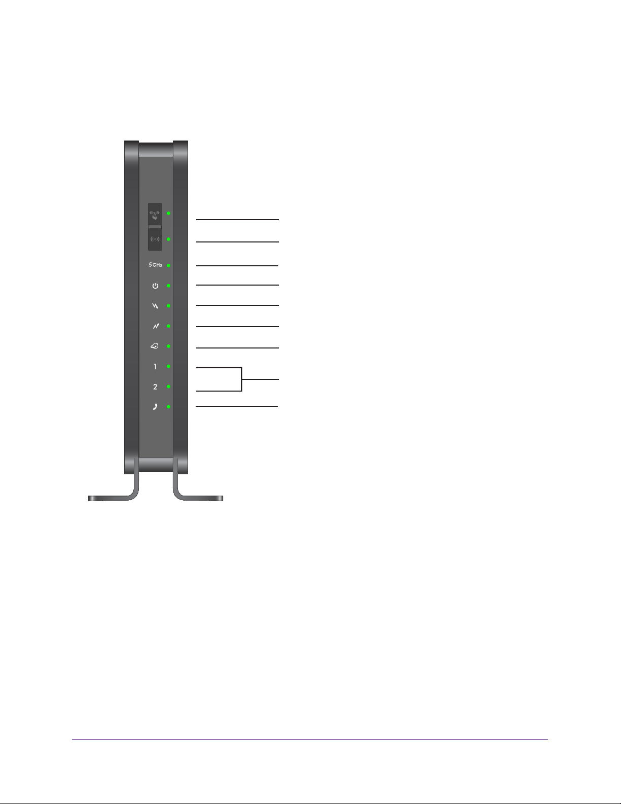
Gateway Front Panel
The gateway front panel has the buttons and status LEDs shown in the following figure.
WPS button / LED
Wireless button / 2.4 GHz LED
5 GHz LED
Power LED
Downstream LED
Upstream LED
Internet LED
LAN (Ethernet) LEDs
Phone LED
Figure 1. Gateway buttons and LEDs
You can use the LEDs to verify status and connections. The following table lists and
describes each LED and button on the front panel of the gateway.
Connect to the Gateway
7
Page 8
Wireless Cable V oice Gateway CG3700EMR-1CMNDS
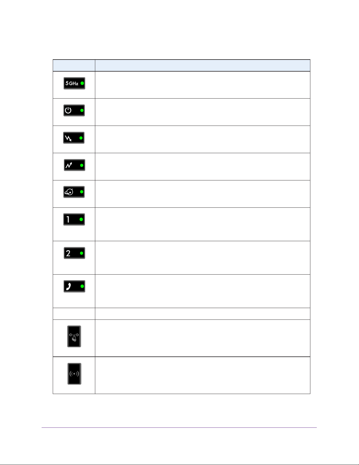
Table 1. Gateway LED descriptions
LED Description
• Solid green. The gateway has 5 GHz connectivity.
• Off.
The gateway does not have 5 GHz connectivity or the power is off.
Power
Downstream
Upstream
Internet
LAN (
Ethernet)
Ethernet)
LAN (
• Solid green. The
• Blinking green. Power-on self-test is in progress.
• Off.
• Solid green. More than one channel is locked (channel bonding).
• Blinking green.
• Off. No downstream channel is locked.
• Solid green. More than one channel is locked (channel bonding).
• Blinking green.
• Off. No upstream channel is locked.
• Solid green. The
• Blinking green.
• Off. The
• Solid green.
• Blinking green. Data is being transmitted or received on the Ethernet port.
• Off. The
• Solid green.
• Blinking green. Data is being transmitted or received on the Ethernet port.
• Off. The
The gateway does not have power.
gateway is offline.
powered on.
gateway does not detect an Ethernet device.
powered on.
gateway does not detect an Ethernet device.
gateway has power.
The unit is scanning for a downstream channel.
The unit is scanning for an upstream channel.
gateway is online.
The gateway is synchronizing with the CMTS of the cable provider.
The gateway detects an Ethernet device connected to the port and is
The gateway detects an Ethernet device connected to the port and is
• Solid green.
• Blinking green.
Phone
Button Description
WPS
Wireless On/Off
• Off.
Pressing this button opens a two minute window for the gateway to connect with other
WPS-enabled devices.
Turn the wireless radio in the gateway on and off. The wireless radio is on by default. The
LED located below this button indicates if the wireless radio is on or of
The gateway does not detect a phone connected to the phone port or the phone
is off line.
The gateway detects a phone connected to the port and is powered on.
A phone is connected to the phone port and is in use.
f.
Connect to the Gateway
8
Page 9
Wireless Cable V oice Gateway CG3700EMR-1CMNDS
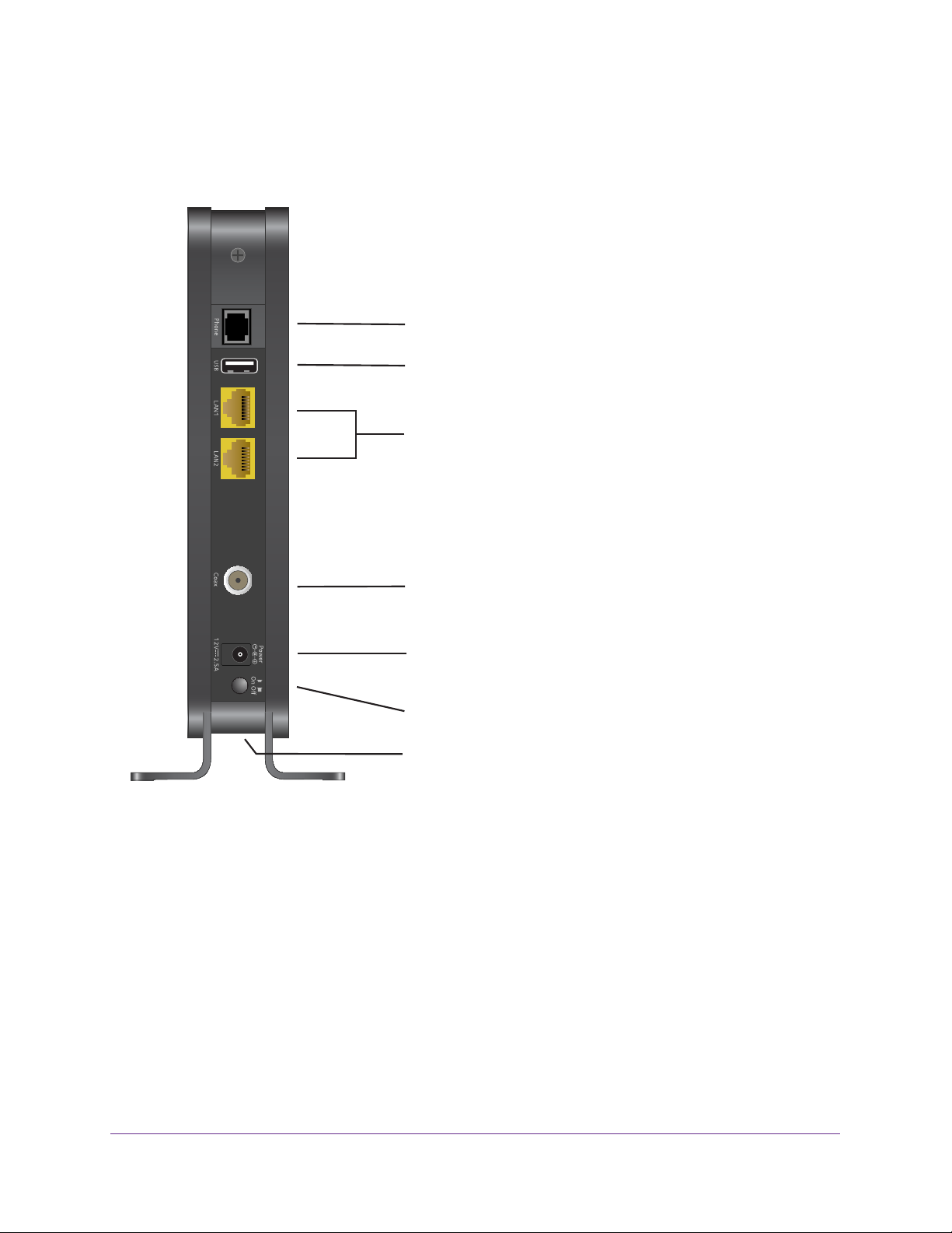
Gateway Rear Panel
The rear panel has the connections and buttons shown in the following figure.
Phone port
USB port (optional)
Ethernet LAN ports
Coaxial cable connector
Power adapter input
Power On/Off button
Reset button
Figure 2. Rear panel connections and buttons
The rear panel includes the following connections, viewed from top to bottom:
• Phone port. Connect a telephone to this port using an analog phone line.
• T
wo Gigabit Ethernet LAN ports. Use these ports to connect local computers.
• Coaxial cable connector. Attach
a coaxial cable to the cable service provider connection.
• Power adapter input. Connect the power adapter unit here.
• Power On/Off button. Press to turn on power
• Reset button.
You can return the gateway to its factory settings. Press and hold the
. Press again to turn off power.
Reset button for over seven seconds. The gateway resets and returns to its factory
settings. See Factory Default Settings on page 72.
Connect to the Gateway
9
Page 10
Wireless Cable V oice Gateway CG3700EMR-1CMNDS
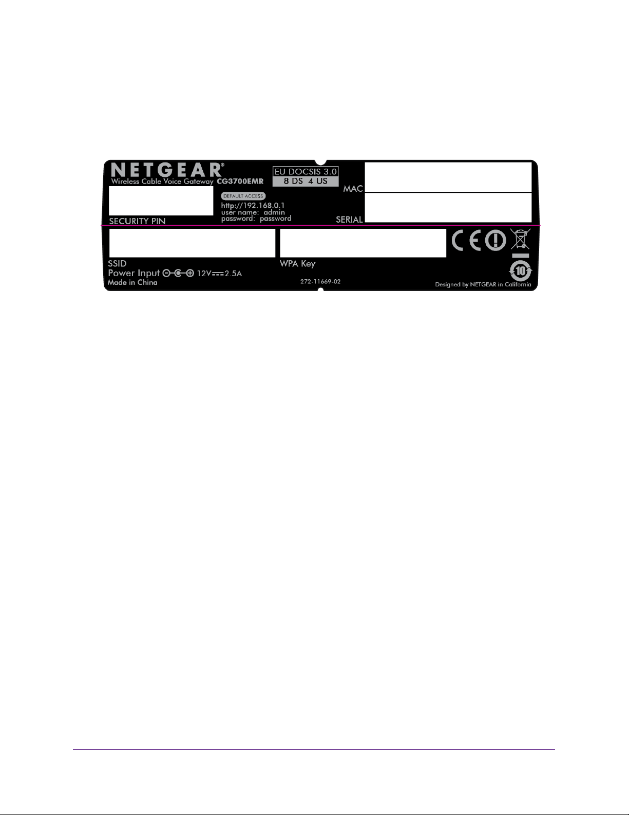
Gateway Label
The label on the gateway shows the PIN, login information, MAC address, serial number,
SSID, and WPA key.
Figure 3. The label shows unique information about your gateway
Power Supply Manufacturers and Models
Use only power supplies listed here:
• Adaptor of CWT
Manufacturer: Channel Well Technology Co., Ltd.
Model: SAS030F2
• Adaptor of PI
Manufacturer: PI Electronics (H.K.) Ltd.
Model: P030WE120B11200
Position Your Gateway
The range of your wireless connection can vary based on the physical placement of the
gateway. The latency, data throughput performance, and notebook power consumption of
wireless adapters also vary depending on your configuration choices.
For best results, place your gateway according to the following guidelines:
• Near the center of the area in which your computers operate.
• In an elevated location such as a high shelf where the wirelessly connected
computers have line-of-sight access (even if through walls).
• A
way from sources of interference, such as computers, microwave ovens, and 2.4
GHz cordless phones.
• A
way from large metal surfaces.
Connect to the Gateway
10
Page 11
Wireless Cable V oice Gateway CG3700EMR-1CMNDS
• To reduce interference when using more than one access point, best practice is to
use channel spacing between adjacent access points (for example, use Channels 1
and 6, or 6 and 11).
Note: Failure to follow these guidelines can result in significant
performance degradation or inability to connect wirelessly to the
gateway.
Log In to Your Gateway
You can log in to the gateway to view or change its settings.
Note: To connect to the gateway, use a computer that is configured for
DHCP (most computers are). For help with configuring DHCP, see
the instructions that came with your computer.
The gateway automatically logs you out after five minutes of no activity.
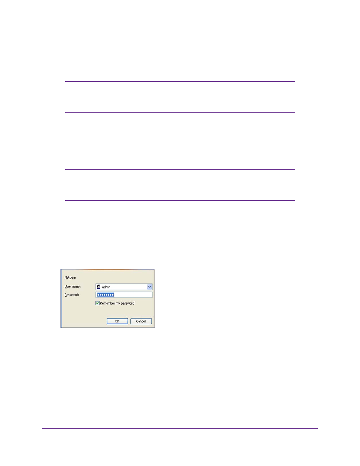
To log in to the gateway:
1. On the computer that is connected to the gateway with an Ethernet cable, type
http://192.168.0.1 in the address field of your Internet browser
A login screen opens.
2. Log in with the user name admin and its default password of password.
The gateway BASIC Home screen displays when you log in (see BASIC Home Screen on
page 12).
.
View the Gateway Home Screens
The gateway home screens include a BASIC Home screen and an ADVANCED Home
screen.
Connect to the Gateway
11
Page 12
Wireless Cable V oice Gateway CG3700EMR-1CMNDS
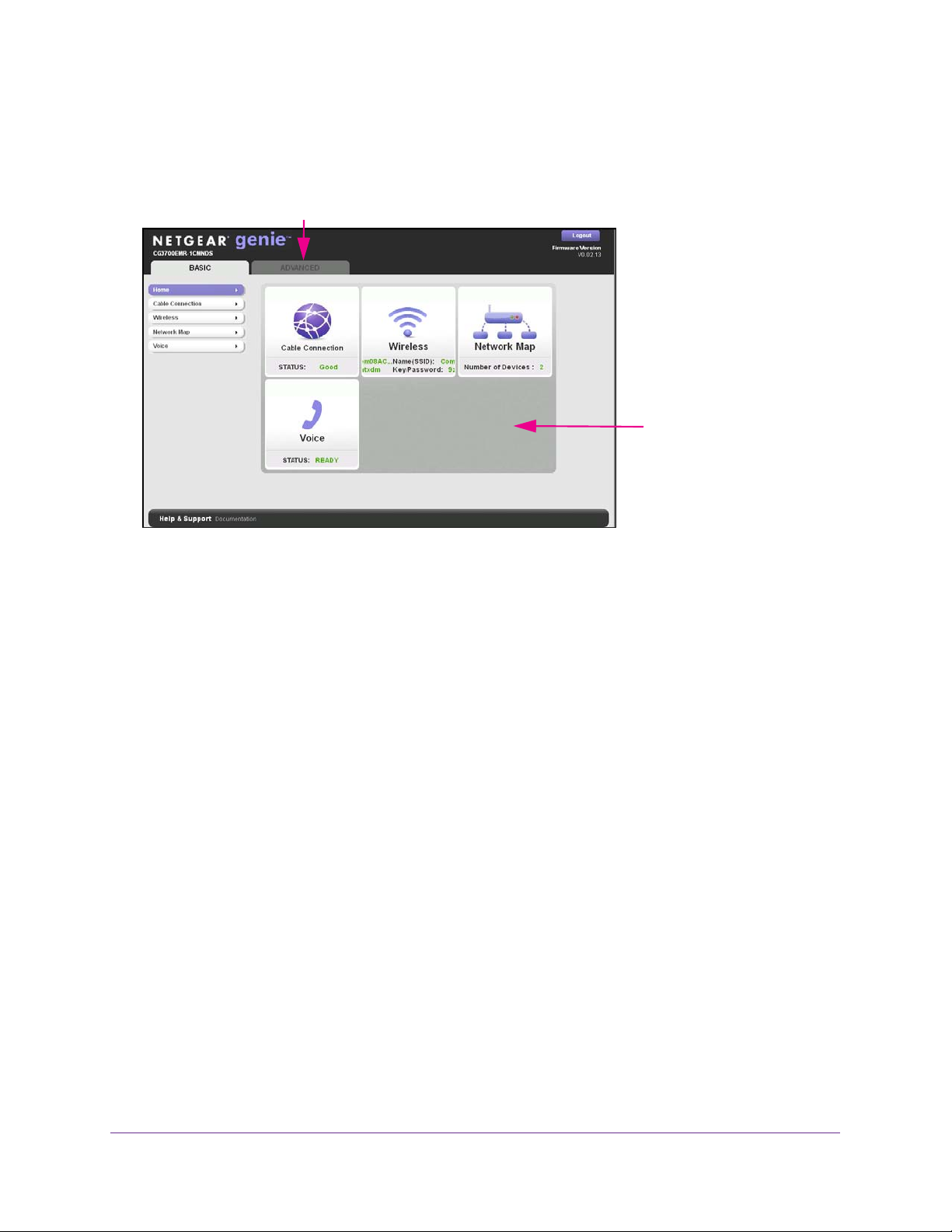
BASIC Home Screen
When you connect to the gateway, the gateway dashboard (BASIC Home screen) displays.
Menus (Click the ADVANCED tab to view more)
Dashboard
(Click to view
details)
Figure 4. NETGEAR genie BASIC home screen
The BASIC Home screen has a dashboard that shows the status of your Internet connection
and network. You can click the sections of the dashboard to view more detailed information.
The left column has menus and an ADVANCED tab displays at the top that you can use to
access more menus and screens.
The following options display on the BASIC home screen:
• Home.
This dashboard screen displays when you log in to the gateway or select the
Home tab.
• Cable Connection.
This option displays the cable signal quality , the upstream power, the
downstream power, and the connection status.
• W
ireless. Select this option to view or change the wireless settings for your gateway.
• Network Map. Select this option to view the devices that are connected to your network.
• V
oice. This option displays the voice status.
• ADV
ANCED tab. Click the ADVANCED tab to set up the gateway for unique situations
such as when remote access by IP or by domain name from the Internet is needed. See
ADVANCED Home Screen on page 13. Using this tab requires a solid understanding of
networking concepts.
For more information about the basic settings, see Chapter 2, NETGEAR genie Basic
Settings.
Connect to the Gateway
12
Page 13
Wireless Cable V oice Gateway CG3700EMR-1CMNDS
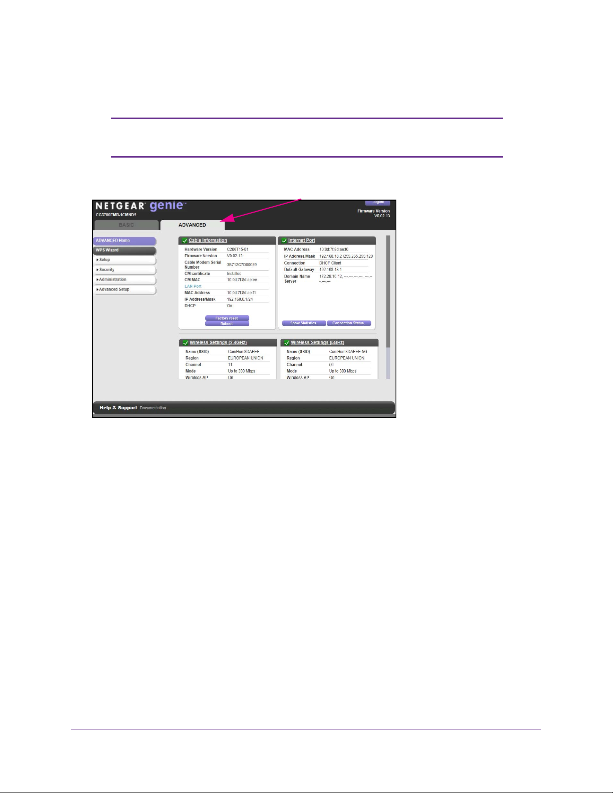
ADVANCED Home Screen
Note: Using the ADVANCED Home screen requires a solid understanding
of networking concepts.
To view the ADVANCE Home screen, click the ADV
The gateway ADVANCED Home screen has a dashboard that lets you see the configuration
of your gateway and network at a glance. You can click any of the sections of the dashboard
to view more detailed information. The left column has the menus and at the top a BASIC tab
displays that you can use to access the basic menus and screens.
ANCED tab.
• ADV
• Setup. Set up the Internet connection, wireless settings, W
• Security. Block sites, block services, and set up email notifications.
• Administration. V
• Advanced Setup. Configure advanced network features such as port forwarding, port
• BASIC tab. Return to the BASIC Home screen. See BASIC Home Screen on page 12.
For more information about the advanced settings, see Chapter 3, NETGEAR genie
ADVANCED Home.
ANCED Home. This dashboard screen displays when you click the ADVANCED tab.
AN, and LAN.
iew gateway status, logs, and event logs, back up and restore the
configuration file, and change the gateway password.
triggering, Dynamic DNS, and UPnP
Connect to the Gateway
.
13
Page 14

Wireless Cable V oice Gateway CG3700EMR-1CMNDS
Join the Wireless Network
To join the wireless network:
1. Open the software that manages your wireless connections on the wireless device
(laptop computer, gaming device, iPhone) that you want to connect to your gateway.
This software scans for all wireless networks in your area.
2. Look for your network and select it.
If you did not change the name of your network during the setup process, look for the
default WiFi network name (SSID) and select it. The default SSID is on the label on the
gateway.
3. Enter the gateway password and click the Connect button.
The default password is on the label on the gateway.
Connect to the Gateway
14
Page 15

2. NETGEAR genie Basic Settings
Your Internet connection and network
2
This chapter explains the features available from the genie BASIC Home screen. This chapter
contains the following sections:
• Cable Connection
• View or Configure Your Wireless Network
• Network Map
• Voice Status
15
Page 16
Wireless Cable V oice Gateway CG3700EMR-1CMNDS
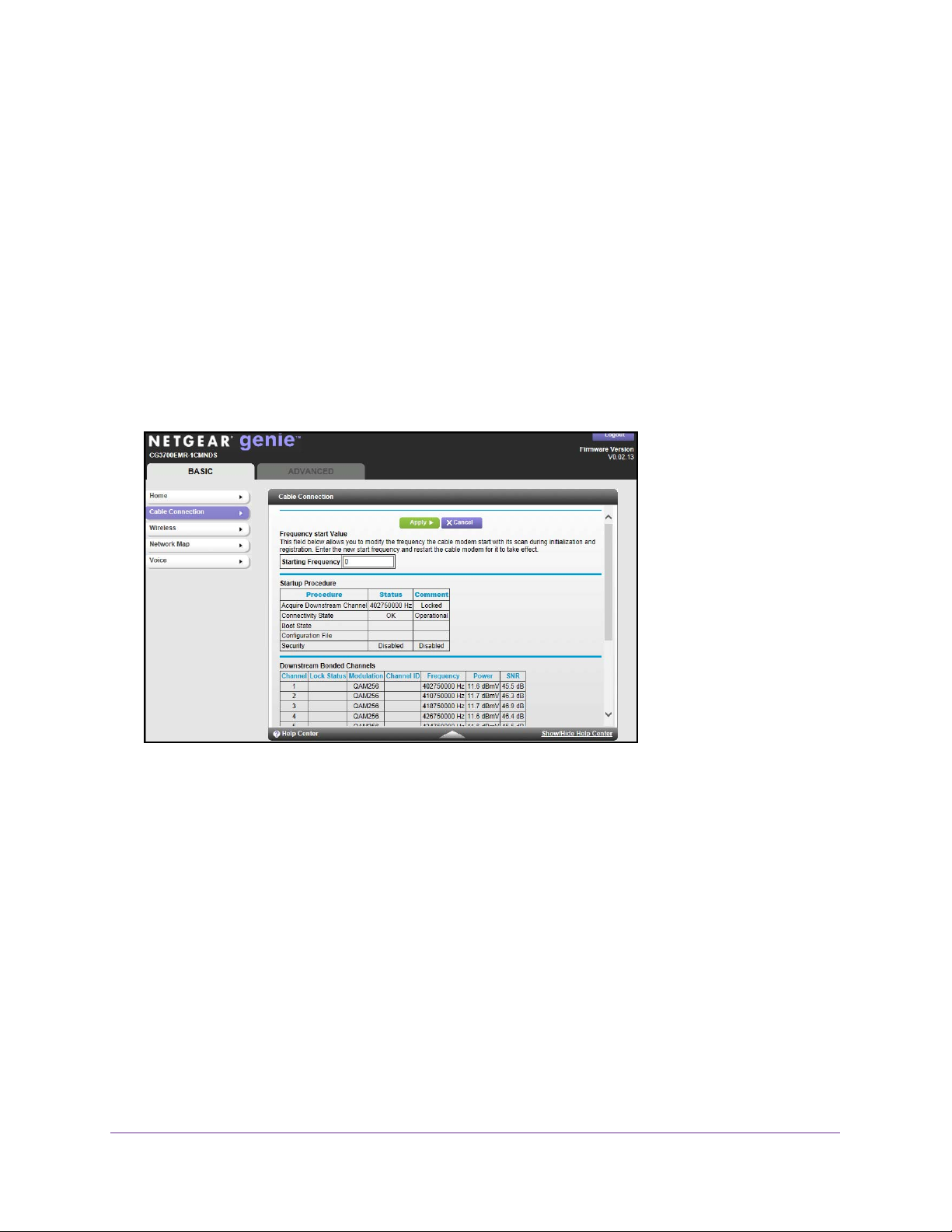
Cable Connection
Use the Cable Connection screen to track the initialization procedure of the gateway, and to
get details about the downstream and upstream cable channel. The time is displayed after
the gateway is initialized.
The gateway automatically goes through the following steps in the provisioning process:
1. Scans and locks the downstream frequency and then ranges the upstream channels.
2. Obtains a W
3. Connects to the Internet.
To change the starting frequency:
From the BASIC tab, select Cable Connection.
AN address for the gateway.
The starting frequency is automatically generated. Most of the time, you do not need to enter
a value in this field. If you need to enter a starting frequency, contact your Internet service
provider.
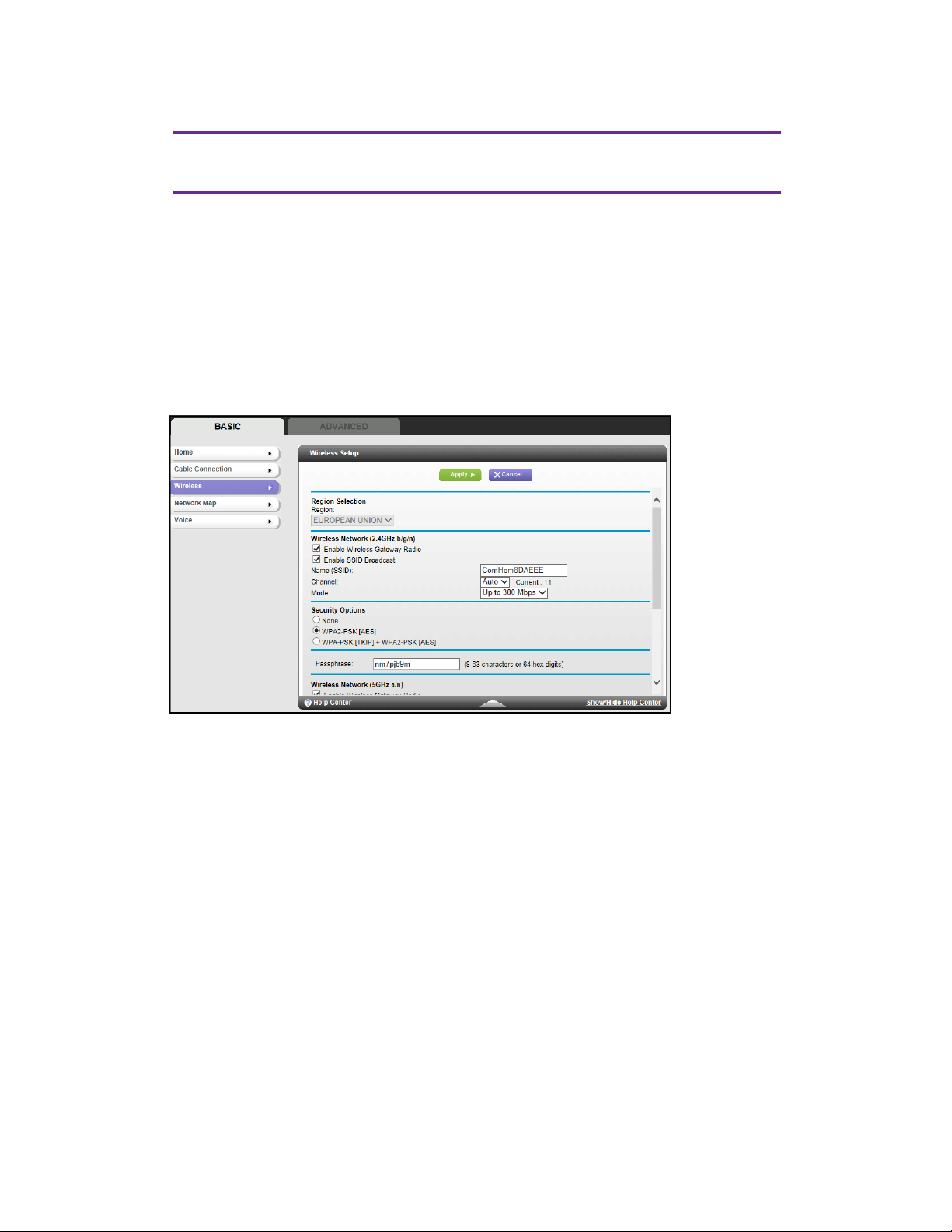
View or Configure Your Wireless Network
The Wireless Setup screen lets you view or configure the wireless network set-up.
The wireless cable gateway comes with preset security. This means that the WiFi network
name (SSID), network key (password), and security option (encryption protocol) are preset in
the factory
. You can find the preset SSID and password on the label of the unit.
NETGEAR genie Basic Settings
16
Page 17
Wireless Cable V oice Gateway CG3700EMR-1CMNDS
Note: The preset SSID and password are uniquely generated for every
device to protect and maximize your wireless security.
Best practice is not change your preset security settings. If you do decide to change
your preset security settings, make a note of the new settings and store it in a safe place.
If you use a wireless computer to change the wireless network name (SSID) or other wireless
security settings, you are disconnected when you click the
Apply button. To avoid this
problem, use a computer with a wired connection to access the gateway.
To view or change basic wireless settings:
1. From the BASIC tab, select W
ireless.
The screen sections, settings, and procedures are explained in the following sections.
2. Make the appropriate changes.
3. Click the Apply button.
Your settings are saved.
4. Set up and test your wireless devices and computers to make sure that they can connect
wirelessly
. If they do not, check the following:
• Is your wireless device or computer connected to your network or another wireless
network in your area? Some wireless devices automatically connect to the first open
network (without wireless security) that they discover
.
• Does your wireless device or computer appear on the Network Map screen? If it does,
it is connected to the network.
• If you are not sure what the network name (SSID) or password is, look on the label on
your gateway.
NETGEAR genie Basic Settings
17
Page 18
Wireless Cable V oice Gateway CG3700EMR-1CMNDS
Wireless Setup Screen Fields
The Fragmentation Length, CTS/RTS Threshold, and Preamble Mode options in this screen
are reserved for wireless testing and advanced configuration only. Do not change these
settings unless you have a specific reason to do so.
• Region Selection. Select the location where the gateway is used.
• Enable W
the wireless interface, clear the Enable Wireless Gateway Radio check box, and click the
Apply button.
• Enable SSID Broadcast.
wireless stations can see this wireless name (SSID) in their scanned network lists. This
check box is selected by default. To turn off the SSID broadcast, clear this check box, and
click the Apply button.
• Name (SSID). The SSID is also known as the wireless network name. Enter a
32-character (maximum) name in this field.
is randomly generated, and best practice is not to change the SSID.
• Channel.
from 1 through 13. (For products in the North America market, only Channels 1 through
11 can be operated.) Do not change the channel unless you experience interference
(such as lost connections or slow data transfers). If any interference happens, experiment
with different channels to see which is the best.
• Mode. Up to 145 Mbps is the default and allows 802.1
join the network. g & b supports up to 54 Mbps. The 300 Mbps setting allows 802.11n
devices to connect at this speed.
ireless Gateway Radio. This setting enables the wireless interface. To turn off
This feature allows the gateway to broadcast its SSID so that
This field is case-sensitive. The default SSID
This setting is the wireless channel that the gateway uses. Choose a value
1n and 802.1 1g wireless devices to
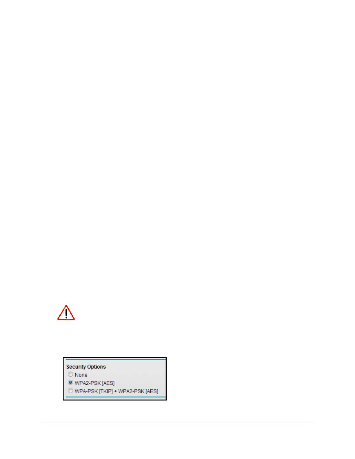
Security Options Settings
The Security Options section of the Wireless Setup screen lets you change the security
option and password. Best practice is not to change the security option or password,
but if you want to change these settings, this section explains how.
CAUTION:
Do not disable security.
To change the WPA security option and password:
1. Under Security Options, select the WP
NETGEAR genie Basic Settings
A option that you want.
18
Page 19
Wireless Cable V oice Gateway CG3700EMR-1CMNDS
2. In the password field that displays when you select a WP A security option, enter the network
key (password) that you want to use. It is a text string from 8 to 63 characters.
3. Click the Apply button.
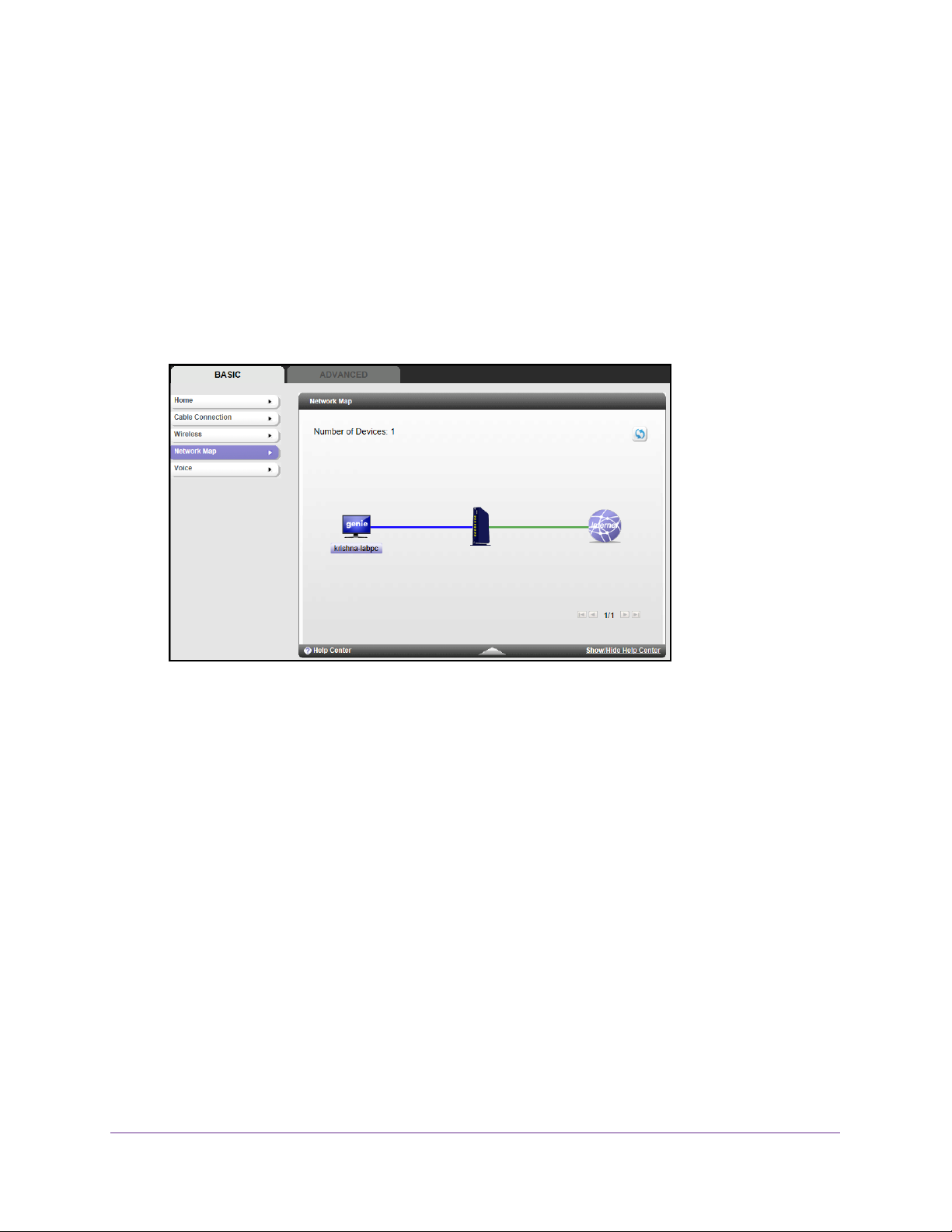
Network Map
You can view all computers or devices that are currently connected to your network here.
To view a map of attached devices:
1. From the BASIC tab, select Network Map.
Wired devices are connected to the gateway with Ethernet cables. Wireless devices have
joined the wireless network. The following information displays:
• IP Address. The IP address that the gateway assigned to this device when it joined
the network. This number can change when a device disconnects and then rejoins
the network.
• Device Name. If the device name is known, it is shown here.
2. T
o update this screen, click the Refresh button.
NETGEAR genie Basic Settings
19
Page 20
Wireless Cable V oice Gateway CG3700EMR-1CMNDS
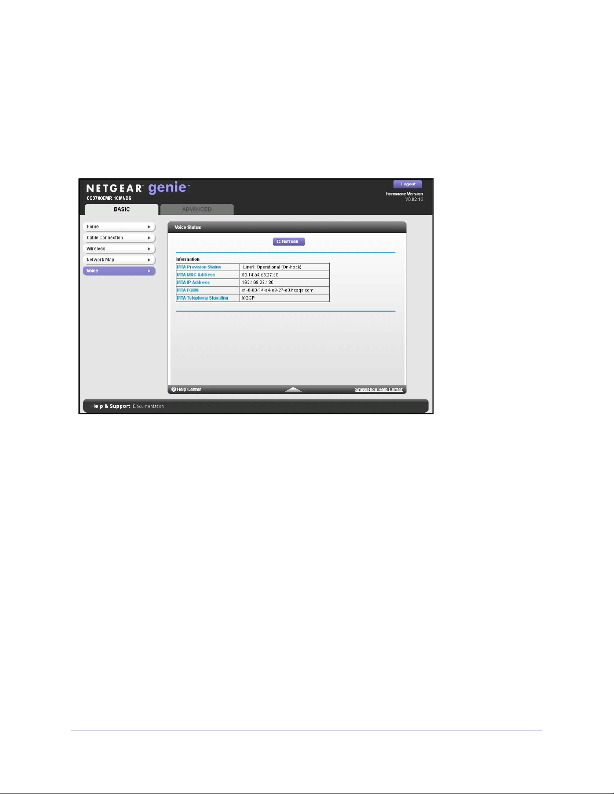
Voice Status
You can review specific details about the voice connection.
To view the status of the voice connection:
From the BASIC tab, select V
The following fields display:
• MT
• MT
• MT
• MT
• MT
A Provision Status. The gateway status. The values can be Operational, No Security
Association, Disconnected, or N/A. This status applies to line 1.
A MAC Address. The telephony MAC address.
A IP Address. The telephony IP address.
A FQDN. The fully qualified domain name (FQDN). The Internet service provider
assigns this name.
A Telephony Signaling. This value is set to Media Gateway Control Protocol
(MGCP), a way to set up voice calls.
oice.
NETGEAR genie Basic Settings
20
Page 21

3. NETGEAR genie ADVANCED Home
Specifying custom settings
3
This chapter explains the features available from the genie ADVANCED Home screen. This
chapter contains the following sections:
• Internet Setup
• WAN Setup
• LAN Setup
Some selections on the ADVANCED Home screen are described in separate chapters:
• Wireless Setup. See Chapter 2, Wireless Setup Screen Fields.
• Security. See Chapter 4, Security.
• Administration. See Chapter 5, Administration.
• Advanced Setup. See Chapter 6, Advanced Settings.
21
Page 22
Wireless Cable V oice Gateway CG3700EMR-1CMNDS
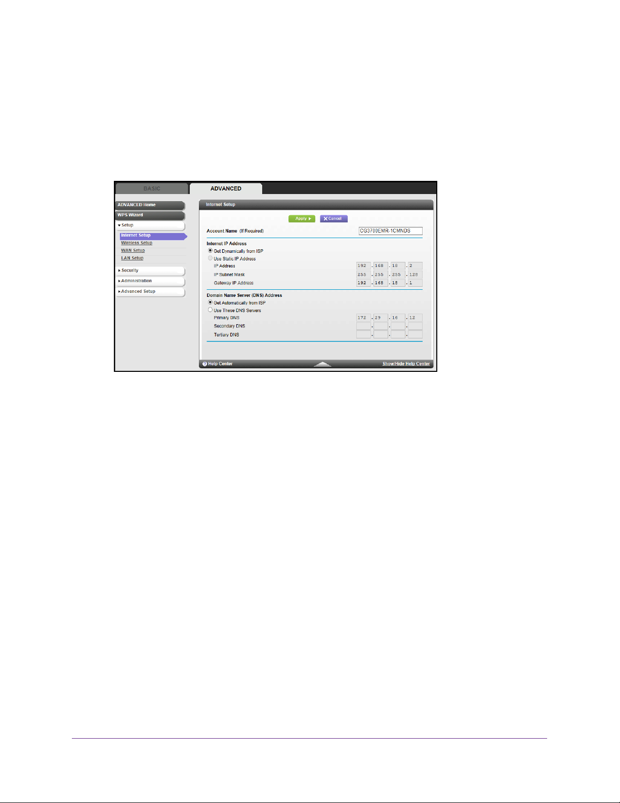
Internet Setup
The Internet Setup screen is where you view or change ISP information.
To change the Internet settings:
1. Select ADV
2. Enter the settings for the IP address and DNS server.
The default settings usually work fine. If you have problems with your connection, check
the ISP settings.
3. Click the Apply button.
ANCED > Setup > Internet Setup.
Your settings are saved.
The following descriptions explain the fields in the Internet Setup screen.
Internet IP Address.
• Get Dynamically from ISP
with a fixed IP address, the gateway finds an IP address for you automatically when you
connect. Select this radio button.
• Use Static IP
you with the required information. Select this radio button and type the IP address, IP
subnet mask, and gateway IP address in the correct fields.
For example:
- IP Address. Enter 24.218.156.183.
- Subnet Mask. Enter 255.255.255.0.
- Gateway IP
Domain Name Server (DNS) Address.
that are based on their names.
Address. If you have a fixed (or static) IP address, your ISP has provided
Address. Enter 24.218.156.1.
. If you log in to your service or your ISP did not provide you
The DNS server is used to look up site addresses
NETGEAR genie ADV ANCED Home
22
Page 23
Wireless Cable V oice Gateway CG3700EMR-1CMNDS
• Use These DNS Servers. If your ISP gave you one or two DNS addresses, select this
radio button and type the primary and secondary addresses.
• Get
Automatically from ISP. Your ISP uses DHCP to assign your DNS servers. Your
ISP automatically assigns this address.
Note: If you get address not found errors when you go to a website, it is
likely that your DNS servers are not set up correctly. Contact your
ISP to get the DNS server addresses.
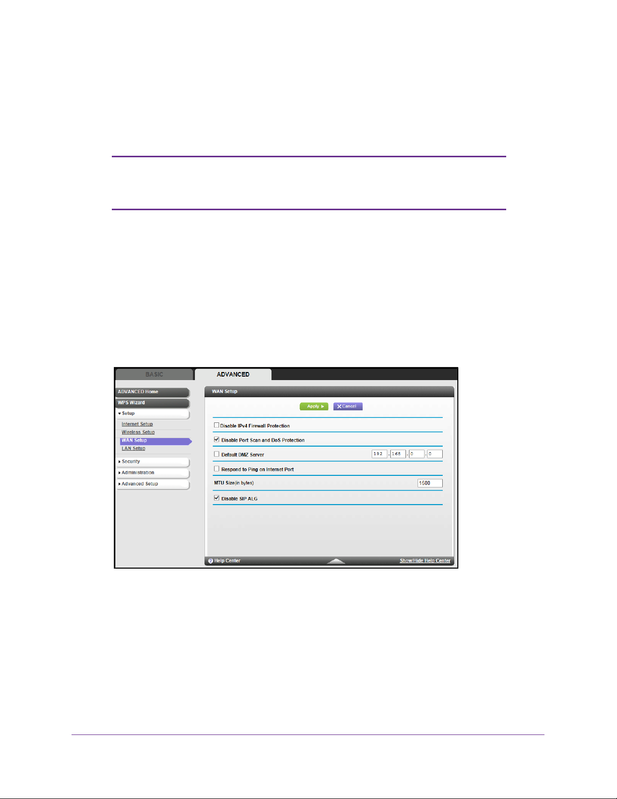
WAN Setup
The WAN Setup screen lets you configure a DMZ (demilitarized zone) server and enable the
gateway to respond to a ping on the WAN (Internet) port.
To change the WAN settings:
1. Select ADV
The following screen displays:
2. Configure the following settings:
• Disable IPv4 Firewall Protection. Firewalls protect your gateway and connected
devices from external attacks.
• Disable Port Scan and DoS Protection. DoS protection protects your LAN against
denial of service attacks such as Syn flood, Smurf
Attack, UDP Flood, ARP Attack, Spoofing ICMP, Null Scan, and many others. Disable
this feature only in special circumstances.
• Default DMZ Server.
some online games and videoconferencing applications that are incompatible with
ANCED > Setup > WAN Setup.
The firewall is enabled by default.
Attack, Ping of Death, Teardrop
The default DMZ server feature is helpful when you are using
NETGEAR genie ADV ANCED Home
23
Page 24

Wireless Cable V oice Gateway CG3700EMR-1CMNDS
Network Address Translation (NAT). The gateway is programmed to recognize some
of these applications and to work correctly with them, but some applications do not
function well. In some cases, one local computer can run the application correctly if
the IP address of that computer is entered as the default DMZ server.
Be careful when using this feature becuase it makes the firewall security less
effective.
• Respond to Ping on Internet Port. If you want the gateway to respond to a ping
from the Internet, select this check box. Use this feature only as a diagnostic tool
because it also allows your gateway to be discovered. Do not select this check box
unless you have a specific reason.
• MTU Size (in bytes). The normal MTU (maximum transmit unit) value for most
Ethernet networks is 1500 bytes, or 1492 bytes for PPPoE connections. For some
ISPs, you might need to reduce the MTU. Reduce the MTU only if you are sure that it
is necessary for your ISP connection.
• Disable SIP/ALG. The Session Initiation Protocol (SIP) Application Level Gateway
(ALG) is disabled by default, which is useful when you are running certain
applications. To enable SIP/ALG and optimize VoIP phone calls that use the SIP,
clear the check box.
WARNING:
DMZ servers pose a security risk. A computer that is designated
as the default DMZ server loses much of the protection of the
firewall and is exposed to exploits from the Internet. If
compromised, the DMZ server computer can be used to attack
other computers on your network.
The gateway discards incoming traffic from the Internet unless the traffic is a response to one
of your local computers or a service that you have configured in the Port Forwarding/Port
Triggering screen. Instead of discarding this traffic, you can have it forwarded to one
computer on your network. This computer is called the default DMZ server.
To set up a default DMZ server:
1. On the WAN Setup screen, select the Default DMZ Server check box.
2. Type the IP address.
3. Click the Apply button.
LAN Setup
The LAN Setup screen allows you to configure LAN services such as the IP address of the
gateway and DHCP. The TCP/IP and DHCP default values work fine in most cases.
The gateway is shipped preconfigured to use private IP addresses on the LAN side and to act
as a DHCP server. The default LAN IP configuration of the gateway is:
NETGEAR genie ADV ANCED Home
24
Page 25

Wireless Cable V oice Gateway CG3700EMR-1CMNDS
• LAN IP address. 192.168.0.1
• Subnet mask. 255.255.255.0
These addresses are part of the designated private address range for use in private networks
and are suitable for most applications. If your network requires you to use a dif
ferent IP
addressing scheme, make those required changes in the LAN Setup screen.
Note: If you change the LAN IP address of the gateway while connected
through the browser, you are disconnected. Open a new connection
to the new IP address and log in again.
To change the LAN settings:
1. Select ADV
ANCED > Setup > LAN Setup.
The following screen displays:
2. Enter the settings that you want to customize. These settings are described in the following
sections.
3. Click the Apply button.
4. Y
our changes are saved.
NETGEAR genie ADV ANCED Home
25
Page 26

Wireless Cable V oice Gateway CG3700EMR-1CMNDS
LAN TCP/IP Setup
Specify the following settings:
• IP Address. The LAN IP address of the gateway.
• IP Subnet Mask. The LAN subnet mask of the gateway. When combined with the IP
address, the IP subnet mask allows a device to know the following:
- Which other addresses are local to it
- Which other addresses must be reached through a gateway
DHCP IP Pool
By default, the gateway functions as a DHCP server. This capability allows the gateway to
assign IP, DNS server, and default gateway addresses to all computers connected to the LAN
that is connected to the gateway. The assigned default gateway address is the LAN address
of the gateway. The gateway assigns IP addresses to the attached computers from a pool of
addresses that are specified in this screen. Each pool address is tested before it is assigned
to avoid duplicate addresses on the LAN. For most applications, the default DHCP and
TCP/IP settings of the gateway are satisfactory.
You can specify the pool of IP addresses that can be assigned by setting the starting IP
address and ending IP address. These addresses are part of the same IP address subnet as
the LAN that is connected to the gateway. Using the default addressing scheme, you define a
range between 192.168.0.2 and 192.168.0.254. You can save part of the range for devices
with fixed addresses.
Specify the following settings:
• Starting IP Address. Specify the start of the range for the pool of IP addresses in the
same subnet as the gateway.
• Ending IP Address. Specify the end of the range for the pool of IP addresses in the
same subnet as the gateway.
The gateway delivers the following parameters to any LAN device that requests DHCP:
• An IP address from the range that you have defined
• Subnet mask
• Gateway IP address (the LAN IP address of the gateway)
• DNS server address (if you entered a primary DNS address in the Internet Setup screen;
otherwise, the LAN IP address of the gateway)
NETGEAR genie ADV ANCED Home
26
Page 27

Wireless Cable V oice Gateway CG3700EMR-1CMNDS
Address Reservation
When you specify a reserved IP address for a computer on the LAN, that computer always
receives the same IP address each time it accesses the DHCP server of the gateway. Assign
reserved IP addresses to computers or servers that require permanent IP settings.
1. Select ADV
The following screen displays:
2. Click the Add button.
ANCED > Setup > LAN Setup.
3. In the IP Address field, type the IP address to assign to the computer or server. (Choose an
IP address from the LAN subnet of the gateway, such as 192.168.0.x.)
4. T
ype the MAC address of the computer or server.
Tip: If the computer is already on your network, copy its MAC address from
Attached Devices screen and paste it here.
the
NETGEAR genie ADV ANCED Home
27
Page 28

Wireless Cable V oice Gateway CG3700EMR-1CMNDS
5. Click the Apply button.
The reserved address is added to the table.
The reserved address is not assigned until the next time the computer contacts the DHCP
server of the gateway. Reboot the computer or access its IP configuration and force a
DHCP release and renew.
To edit or delete a reserved address entry:
1. Select the radio button next to a reserved address.
2. Click the Edit or Delete button.
NETGEAR genie ADV ANCED Home
28
Page 29

4. Security
Keeping unwanted content out of your network
4
This chapter explains how to prevent objectionable content from reaching the computers and
other devices that are connected to your network.
This chapter includes the following sections:
• Keyword Blocking of HTTP Traffic
• Block Services (Port Filtering)
• Schedule Blocking
29
Page 30

Wireless Cable V oice Gateway CG3700EMR-1CMNDS
Keyword Blocking of HTTP Traffic
Use keyword blocking to prevent certain types of HTTP traffic from accessing your network.
1. Select ADV
2. Select one of the keyword blocking options:
• Never.
• Per Schedule.
(See Schedule Blocking on page 32.)
• Always.
ANCED > Security > Block Sites.
Turn off keyword blocking.
Turn on keyword blocking according to the Schedule screen settings.
Turn on keyword blocking.
3. In the keyword field, enter a keyword or domain and click the Add URL Keyword button.
The keyword list supports up to 32 entries. Here are some sample entries:
• Specify XXX to block http://www
• Specify .com if you want to allow only sites with domain suf
• Enter a period (.) to block all Internet browsing access.
4. Click the Apply button.
To delete a keyword or domain:
1. Select the keyword that you want to delete from the list.
2. Click the Delete URL Keyword button.
3. Click the Apply button.
4. Y
our changes are saved.
You can exempt one trusted computer from blocking and logging. The computer that you
exempt must have a fixed IP address.
To specify a trusted computer:
1. Select the Allow trusted IP address to visit blocked sites check box.
.badstuff.com/xxx.html.
fixes such as .edu or .gov.
Security
30
Page 31

Wireless Cable V oice Gateway CG3700EMR-1CMNDS
2. In the Trusted IP Address field, enter the IP address.
3. Click the Apply button.
Your changes are saved.
Block Services (Port Filtering)
Server computers perform services at the request of client computers. For example, web
servers serve web pages, time servers serve time and date information, and game hosts
serve data about players’ moves. When a computer on the Internet sends a request for
service to a server computer, a service or port number identifies the requested service. This
number displays as the destination port number in the transmitted IP packets. For example, a
packet that is sent with the destination port number 80 is an HTTP (web server) request.
The service numbers for many common protocols are defined by the Internet Engineering
ask Force (IETF at http://www.ietf.org/) and published in RFC1700, “Assigned Numbers.”
T
Service numbers for other applications are typically chosen from the range 1024–65535 by
the authors of the application.
numbers, you are not limited to these choices. You can often find port number information by
contacting the publisher of the application, by asking user groups or newsgroups, or by
searching.
Although the gateway already holds a list of many service port
The Block Services screen lets you add and block specific Internet services by computers on
your network.
blocking, first find out which port number or range of numbers the application uses.
To block services:
1. Select ADV
2. Select either the Per Schedule or Always radio button.
3. If you selected Per Schedule, specify a time period in the Schedule screen.
This capability is called service blocking or port filtering. To add a service for
ANCED > Security > Block Services.
For more information see Schedule Blocking on page 32.
Security
31
Page 32

Wireless Cable V oice Gateway CG3700EMR-1CMNDS
4. To add a service, click the Add button.
The Block Services Setup screen displays:
5. From the Service Type list, select the application or service to block.
The list already displays several common services, but you are not limited to these
choices.
User Defined.
6. If you select User Defined, select the protocol, and enter the name and the range of port
numbers of the service.
If you select a known service, these fields are filled in automatically.
If you know that the application uses either TCP or UDP, select the appropriate protocol. If
you are not sure, select TCP/UDP.
7. Enter a name for this service type in the Service
8. Enter the starting and ending port numbers. If the application uses a single port number
enter that number in both fields.
9. Enter the IP address of the computer that you want to block.
10. Click the Add button.
Your Block Services Setup selections are enabled.
To add any additional services or applications that do not already display, select
Type/User Defined field.
Schedule Blocking
You can specify the days and time that you want to block Internet access.
,
To schedule blocking:
1. Select ADV
ANCED > Security > Schedule.
Security
32
Page 33

Wireless Cable V oice Gateway CG3700EMR-1CMNDS
The following screen displays.
2. Click the Add button.
3. Enter a name for this schedule.
4. Set up the schedule for blocking keywords and services:
• Days to Block. Select days on which you want to apply blocking by selecting the
appropriate check boxes, or select Every Day to select the check boxes for all days.
• T
ime of Day to Block. Select a start and end time in 24-hour format, or select All
Day for 24-hour blocking.
5. Click the Apply button.
Your settings are saved.
Security
33
Page 34

5. Administration
Managing your network
5
This chapter describes the gateway settings for administering and maintaining your gateway and
home network.
This chapter includes the following sections:
• View Gateway Status
• Router Mode
• Logs
• Network Map
• Back Up Settings
• Set Password
• View Event Logs
• Diagnostics
• Wireless Channel
34
Page 35

Wireless Cable V oice Gateway CG3700EMR-1CMNDS
View Gateway Status
To view gateway status and usage information:
Select ADVANCED > Administration > Gateway Status.
The following screen displays.
Cable Information
The following information displays:
• Hardware V
• Firmware Version.
gateway firmware.
• Cable Modem Serial Number.
• CM certificate.
status, contact your Internet service provider.
• CM MAC.
• LAN Port.
• MAC Address.
physical address that the Ethernet (LAN) port of the gateway uses.
• IP Address.
default is 192.168.0.1.
• DHCP Server. Identifies whether the built-in DHCP server of the gateway is active for
the LAN-attached devices.
ersion. The gateway model.
The version of the gateway firmware. It changes if you upgrade the
The serial number of the cable modem.
The status of the cable modem certificate. If ‘Not installed’ displays as the
The MAC address of the cable modem.
The Media Access Control address. This address is the unique
The IP address that the Ethernet (LAN) port of the gateway uses. The
To reset the admin and password to the default values, click the Factory Reset button.
To reboot the gateway, click the Reboot button.
Administration
35
Page 36

Wireless Cable V oice Gateway CG3700EMR-1CMNDS
Internet Port
The following information about the WAN Internet port displays:
• MAC Address. The MAC address of the WAN Internet port.
• IP Address/Mask. The IP address of the WAN Internet port.
• Connection. The type of WAN Internet port connection.
• Default Gateway. The IP address of the default gateway.
• Domain Name Server. The IP address of the domain name server.
Wireless Settings (2.4 GHz and 5 GHz)
The following information displays:
• Name (SSID). The wireless network name (SSID) that the gateway uses.
• Region. The geographic region where the gateway is being used. It is illegal to use the
wireless features of the gateway in some parts of the world.
• Channel. The operating channel of the wireless port being used. The default channel is
Auto. When Auto is selected, the gateway finds the best operating channel available.
• Mode. The wireless communication mode: Up to 54 Mbps, Up to 145 Mbps (default), or
Up to 300 Mbps.
• Wireless AP. Indicates whether the radio feature of the gateway is enabled. If this feature
is not enabled, the Wireless LED on the front panel is off.
• Broadcast Name. Indicates whether the gateway is broadcasting its SSID.
• Wireless Isolation. Indicates that the wireless clients can connect to the Internet.
However, they cannot access each other or access Ethernet devices on the network.
• Wi-Fi Protected Setup. Indicates whether Wi-Fi Protected Setup is configured for this
network.
Administration
36
Page 37

Wireless Cable V oice Gateway CG3700EMR-1CMNDS
Router Mode
To set the router mode:
1. Select ADVANCED > Administration > Router Mode.
The following screen displays.
2. Select one of the following radio buttons:
• Ye
• No.
s. The CG3700EMR device works as a gateway and provides connected devices
with IP addresses.
The CG3700EMR device works as a bridge and devices obtain their IP
addresses from the Internet service provider.
Logs
The log is a detailed record of the websites you have accessed or attempted to access. Up to
256 entries are stored in the log. Log entries display only when keyword blocking is enabled.
No log entries are made for the trusted LAN client.
To view the logs:
1. Select ADV
ANCED > Administration > Logs.
Administration
37
Page 38

Wireless Cable V oice Gateway CG3700EMR-1CMNDS
The following screen displays.
The log screen shows the following information:
• Description.
• Count.
• Last Occurance.
• T
arget. The name or IP address of the website or news group visited or to which access
The name and source IP of the site or group that visited.
The number of times the website or news group visited.
The date and time the log entry was recorded.
was attempted.
• Source.
2. T
o control the information included in the log, click any of the following check boxes:
The IP address of the initiating device for this log entry.
• Attempted access to allowed sites.
• Attempted access to blocked sites and services.
• Connections to the W
eb-based interface of this Gateway.
• Gateway operation (startup, get time etc).
• Known DoS attacks and Port Scans.
• Port Forwarding / Port T
riggering.
3. Do any of the following:
o refresh the log screen, click the Refresh button.
• T
• T
o clear the log entries, click the Clear Log button.
• T
o email the log immediately, click the Send Log button.
• T
o save your changes, click the Apply button.
Administration
38
Page 39

Wireless Cable V oice Gateway CG3700EMR-1CMNDS
Network Map
The network map displays information about devices connected to your network.
To view the network map:
Select ADV
The following screen displays.
The following fields display:
• Device Name.
• IP Address.
• MAC Address.
• Interface.
ANCED > Administration > Network Map.
The name of the connected device.
The IP address of the connected device.
The MAC address of the connected device.
The way the device is connected: Ethernet1, Ethernet2, or WiFi interface.
Back Up Settings
The configuration settings of the wireless cable gateway are stored within the gateway in a
configuration file. You can back up (save) this file to your computer, restore it, or reset it to
the factory default settings.
Administration
39
Page 40

Wireless Cable V oice Gateway CG3700EMR-1CMNDS
To back up the configuration settings of the gateway:
1. Select ADVANCED > Administration > Backup Settings.
2. Click the Back Up button.
A copy of the current settings is saved.
Restore Configuration Settings
To restore configuration settings that you backed up:
1. Select ADV
2. T
o find the .cfg file, enter the full path to the file on your network or click the Browse button.
3. Click the Restore button.
The gateway reboots.
ANCED > Administration > Backup Settings.
WARNING:
Do not interrupt the reboot process.
Erase
Under some circumstances (for example, if you move the gateway to a different network or if
you have forgotten the password), you might want to erase the configuration and restore the
factory default settings.
To erase the configuration:
1. Select ADV
2. Click the Erase button.
ANCED > Administration > Backup Settings.
Administration
40
Page 41

Wireless Cable V oice Gateway CG3700EMR-1CMNDS
Erase sets the user name to admin, the password to password, and the LAN IP address
to 192.168.0.1, and enables the DHCP of the gateway.
Set Password
This feature allows you to change the default password that is used to log in to the gateway
with the user name admin.
This gateway password is not the same as the password for wireless access. The label on
your gateway shows your unique wireless network name (SSID) and password for wireless
access (see Gateway Label on page 10).
To set the password for the user name admin:
1. Select ADV
The following screen displays.
2. Type the old password.
3. T
ype the new password in the Set Password field.
4. T
ype the new password in the Repeat New Password field.
5. Click the Apply button.
ANCED > Administration > Set Password.
Your change takes effect.
View Event Logs
Event logs capture important gateway events.
To view the event logs:
1. Select ADV
ANCED > Administration > Event Log.
Administration
41
Page 42

Wireless Cable V oice Gateway CG3700EMR-1CMNDS
The Event Logs screen displays.
The log screen shows the following information:
• T
ime. The time the event log entry was recorded.
• Priority.
• Description.
2. T
o refresh the log screen, click the Refresh button.
3. T
o clear the log entries, click the Clear Log button.
The severity for this event log entry.
A description of this event log entry.
Diagnostics
From the Diagnostics screen, you can run ping, traceroute, DS throughput, and US
throughput utilities.
Ping Utility
Ping is an administration utility that tests whether a computer on the network is reachable and
measures the time it takes messages sent from the originating device to reach a destination
computer and return.
To run a ping test:
1. Select ADV
ANCED > Administration > Diagnostics.
Administration
42
Page 43

Wireless Cable V oice Gateway CG3700EMR-1CMNDS
The following screen displays.
2. In the Utility list, select Ping.
3. Specify the following parameters for the ping utility
arget. The IP address of the ping target computer.
• T
• Ping Size.
• No. of Pings.
• Ping Interval.
4. Click the Start T
The size (in bytes) of the ping packet.
The number of times to ping the target computer.
The time between pings.
est button.
.
The ping results display.
To stop a ping test:
Click the Abort T
To clear the results from the display:
est button.
Click the Clear Results button.
Traceroute Utility
To display the route and measure transit delays of packets across a network, run the
traceroute utility.
To run a traceroute test:
1. Select ADV
ANCED > Administration > Diagnostics.
Administration
43
Page 44

Wireless Cable V oice Gateway CG3700EMR-1CMNDS
The following screen displays.
2. In the Utility list, select Traceroute.
3. Specify the following parameters for the traceroute utility:
• Target. The IP address or host name of the computer you are tracing.
• Max Hops.
• Data Size.
• Base Port.
The maximum number of hops to allow when tracing the route.
The size (in bytes) of the packet.
The port number to send the packet to.
• Resolve Host. Select On to resolve the host name to the IP address.
4. Click the Start T
est button.
The traceroute results display.
To clear the results from the display:
Click the Clear Results button.
DS Throughput Utility
To display the speed test for downstream traffic, run the DS throughput utility.
To run a DS throughput test:
1. Select ADV
ANCED > Administration > Diagnostics.
Administration
44
Page 45

Wireless Cable V oice Gateway CG3700EMR-1CMNDS
The following screen displays.
2. In the Utility list, select DS throughput.
3. Click the Start T
est button.
The DS throughput results display.
To clear the results from the display:
Click the Clear Results button.
US Throughput Utility
To display the speed test for upstream traffic, run the US throughput utility.
To run a US throughput test:
1. Select ADV
ANCED > Administration > Diagnostics.
Administration
45
Page 46

Wireless Cable V oice Gateway CG3700EMR-1CMNDS
The following screen displays.
2. In the Utility list, select US throughput.
3. Click the Start T
est button.
The US throughput results display.
To clear the results from the display:
Click the Clear Results button.
Wireless Channel
You can use the Wireless Channel screen to view wireless networks, or access points, in
your area and to select and join a wireless network.
To manage your wireless access point (AP):
Select ADV
ANCED > Administration > Wireless AP.
Administration
46
Page 47

Wireless Cable V oice Gateway CG3700EMR-1CMNDS
The following screen displays:
From this screen, you can view wireless access points in use in your area.
To check your wireless channel:
Select Advanced > Administration > W
ireless Channel.
The following screen displays:
Your network is shown in blue. Yellow shows other networks in your area. Many countries
and geographic locations have laws or guidelines about which channels can be used.
Depending on your location, some channels might not be available.
If many wireless networks at your location use the same channel as your wireless network,
you might experience interference.
To change the wireless channel:
You can change the channel to avoid the interference.
1. Click the Change Channel button.
Administration
47
Page 48

Wireless Cable V oice Gateway CG3700EMR-1CMNDS
The following screen displays.
2. Select a different channel.
For information about other options available on this screen, see View or Configure Your
Wireless Network on page 16.
3. Click the Apply button.
Your change takes effect.
Administration
48
Page 49

6. Advanced Settings
Fine-tuning your network
6
This chapter describes the advanced features of your gateway. The information requires a solid
understanding of networking concepts. It is for people who want to set up the gateway for unique
situations such as when remote access from the Internet by IP or domain name is needed.
This chapter includes the following sections:
• Advanced Wireless Settings
• Port Forwarding and Port Triggering
• Set Up Port Forwarding to Local Servers
• Set Up Port Triggering
• Dynamic DNS
• Remote Management
• Universal Plug and Play
49
Page 50

Wireless Cable V oice Gateway CG3700EMR-1CMNDS
Advanced Wireless Settings
You can use this screen to specify WPS settings and to set up a wireless card access list.
View or Change WPS Settings
To view or change WPS settings:
1. Select ADV
The following screen displays.
Specify the following settings:
• Disable Gateway’
gateway detects suspicious attempts to break into the gateway’s wireless settings by
using the gateway’s PIN through WPS. You can manually enable the PIN function by
clearing the Disable Gateway’s PIN check box.
• Keep Existing W
box is selected. Best practice is to leave this check box selected.
ANCED > ADVANCED Setup > Wireless Features.
s PIN. The PIN function might temporarily be disabled when the
ireless Settings. By default, the Keep Existing Wireless Settings check
If you clear this check box, the next time a new wireless client uses WPS to connect to
the gateway, the gateway wireless settings change to an automatically generated random
SSID and security key.
• WMM. WMM (Wireless Multimedia) is a subset of the 802.1
wireless traffic to have a range of priorities, depending on the kind of data.
Time-dependent information, like video or audio, has a higher priority than normal traffic.
For WMM to function properly, wireless clients must support WMM also.
• WMM Support. Click this check box to enable WMM support for the 2.4 GHz channel.
• WMM Support (5 GHz a/n). Click this check box to enable WMM support for the 5
GHz channel.
Advanced Settings
50
1e standard. WMM allows
Page 51

Wireless Cable V oice Gateway CG3700EMR-1CMNDS
Wireless Card Access List
By default, any wireless computer or device that is configured with the correct SSID is
allowed access to your wireless network. For increased security, allow only specific wireless
computers and devices to access the wireless network based on their MAC addresses.
To set up wireless card access:
1. Select ADV
2. Click the Set Up
ANCED > Advanced Setup > Wireless Features.
Access List button.
3. Select the Turn Access Control On check box.
If the Turn Access Control On check box is selected, and the access control list is blank,
then no wireless computers or devices can connect to your wireless network.
4. Click the Add button.
The Wireless Card Access List setup screen displays.
Advanced Settings
51
Page 52

Wireless Cable V oice Gateway CG3700EMR-1CMNDS
This screen displays a list of currently active wireless computers and devices and their
Ethernet MAC addresses.
5. If the wireless computer or device you want displays in the list, select its radio button to
capture its MAC address. Otherwise, type its MAC address.
The MAC address is found on the computer or device.
6. If no device name displays, type a descriptive name for the computer or device that you are
adding.
7. Click the Add button.
The Wireless Card Access List screen displays.
8. Click the Apply button.
Port Forwarding and Port Triggering
By default, the gateway blocks inbound traffic from the Internet to your computers except for
replies to your outbound traffic. Create exceptions to this rule for these purposes:
• To allow remote computers on the Internet to access a server on your local network.
• To allow certain applications and games to work correctly when your gateway does not
recognize their replies.
Your gateway provides two features for creating these exceptions: port forwarding and port
triggering. The next sections provide background information to help you understand how
port forwarding and port triggering work, and the differences between the two.
Remote Computer Access Basics
When a computer on your network accesses a computer on the Internet, your computer
sends your gateway a message containing the source and destination address and process
information. Before forwarding your message to the remote computer, your gateway must
modify the source information and create and track the communication session so that
replies can be routed back to your computer.
Here is an example of normal outbound traffic and the resulting inbound responses:
1. You open a browser, and your operating system assigns port number 5678 to this
browser session.
2. You type http://www.example.com into the URL field, and your computer creates a web page
request message with the following address and port information. The request message is
sent to your gateway:
• Source address. The IP address of your computer.
• Source port number. 5678, which is the browser session.
• Destination address. The IP address of www.example.com, which your computer
finds by asking a DNS server.
Advanced Settings
52
Page 53

Wireless Cable V oice Gateway CG3700EMR-1CMNDS
• Destination port number. 80, which is the standard port number for a web server
process.
3. Your gateway creates an entry in its internal session table describing this communication
session between your computer and the web server at www.example.com. Before sending
the web page request message to www.example.com, your gateway stores the original
information and then modifies the source information in the request message, performing
Network Address Translation (NAT):
• The source address is replaced with the public IP address of your gateway. This step
is necessary because your computer uses a private IP address that is not globally
unique and cannot be used on the Internet.
• The source port number is changed to a number that is chosen by the gateway, such
as 33333. This step is necessary because two computers could independently be
using the same session number.
Your gateway then sends this request message through the Internet to the web server at
www.example.com.
4. The web server at www.example.com composes a return message with the requested web
page data. The return message contains the following address and port information. The
web server then sends this reply message to your gateway:
• Source address. The IP address of www.example.com.
• Source port number. 80, which is the standard port number for a web server
process.
• Destination address. The public IP address of your gateway.
• Destination port number. 33333.
5. When your gateway receives the incoming message, it checks its session table for an active
session for port number 33333. Finding an active session, the gateway then modifies the
message to restore the original address information that is replaced by NAT. Your gateway
sends this reply message to your computer, which displays the web page from
www.example.com. The message now contains the following address and port information:
• Source address. The IP address of www.example.com.
• Source port number. 80, which is the standard port number for a web server
process.
• Destination address. The IP address of your computer.
• Destination port number. 5678, which is the browser session that made the initial
request.
6. When you finish your browser session, your gateway eventually detects a period of inactivity
in the communications. Your gateway then removes the session information from its session
table, and incoming traffic is no longer accepted on port number 33333.
Port Triggering to Open Incoming Ports
In the preceding example, requests are sent to a remote computer by your gateway from a
particular service port number, and replies from the remote computer to your gateway are
directed to that port number. If the remote server sends a reply to a different port number,
your gateway does not recognize it and discards it. However, some application servers (such
Advanced Settings
53
Page 54

Wireless Cable V oice Gateway CG3700EMR-1CMNDS
as FTP and IRC servers) send replies to multiple port numbers. Using the port triggering
function of your gateway, you can tell the gateway to open more incoming ports when a
particular outgoing port originates a session.
An example is Internet Relay Chat (IRC). Your computer connects to an IRC server at
destination port 6667. The IRC server not only responds to your originating source port, but
also sends an “identify” message to your computer on port 1 13. Using port triggering, you can
tell the gateway, “When you initiate a session with destination port 6667, you must allow
incoming traffic also on port 113 to reach the originating computer.” Using steps similar to the
preceding example, the following sequence shows the effects of the port triggering rule you
have defined:
1. You open an IRC client program to start a chat session on your computer.
2. Your IRC client composes a request message to an IRC server using a destination port
number of 6667, the standard port number for an IRC server process. Your computer then
sends this request message to your gateway.
3. Your gateway creates an entry in its internal session table describing this communication
session between your computer and the IRC server. Your gateway stores the original
information, performs Network Address Translation (NAT) on the source address and port,
and sends this request message through the Internet to the IRC server.
4. Noting your port triggering rule and having observed the destination port number of 6667,
your gateway creates an additional session entry to send any incoming port 113 traffic to
your computer.
5. The IRC server sends a return message to your gateway using the NAT-assigned source
port (as in the previous example, say port 33333) as the destination port. The IRC server
also sends an identify message to your gateway with destination port 113.
6. When your gateway receives the incoming message to destination port 33333, it checks its
session table for an active session for port number 33333. Finding an active session, the
gateway restores the original address information that is replaced by NAT and sends this
reply message to your computer.
7. When your gateway receives the incoming message to destination port 113, it checks its
session table and finds an active session for port 113 associated with your computer. The
gateway replaces the destination IP address of the message with the IP address of your
computer and forwards the message to your computer.
8. When you finish your chat session, your gateway eventually senses a period of inactivity in
the communications. The gateway then removes the session information from its session
table, and incoming traffic is no longer accepted on ports 33333 or 113.
To configure port triggering, you need to know which inbound ports the application needs.
Also, you need to know the number of the outbound port that triggers the opening of the
inbound ports. You can usually find this information by contacting the publisher of the
application or user groups or newsgroups.
Note: Only one computer at a time can use the triggered application.
Advanced Settings
54
Page 55

Wireless Cable V oice Gateway CG3700EMR-1CMNDS
Port Forwarding to Permit External Host Communications
In both of the preceding examples, your computer initiates an application session with a
server computer on the Internet. However, you need to allow a client computer on the
Internet to initiate a connection to a server computer on your network. Normally, your
gateway ignores any inbound traffic that is not a response to your own outbound traffic. You
can configure exceptions to this default rule by using the port forwarding feature.
A typical application of port forwarding can be shown by reversing the client-server
relationship from the previous web server example. In this case, a browser on a remote
computer accesses a web server running on a computer in your local network. Using port
forwarding, you can tell the gateway, “When you receive incoming traffic on port 80 (the
standard port number for a web server process), forward it to the local computer at
192.168.0.123.” The following sequence shows the effects of the port forwarding rule you
have defined:
1. The user of a remote computer opens a browser and requests a web page from
www.example.com, which resolves to the public IP address of your gateway. The
remote computer composes a web page request message with the following destination
information:
• Destination address. The IP address of www.example.com, which is the address of
your gateway.
• Destination port number. 80, which is the standard port number for a web server
process.
The remote computer then sends this request message through the Internet to your
gateway.
2. Your gateway receives the request message and looks in its rules table for any rules
covering the disposition of incoming port 80 traffic. Your port forwarding rule specifies that
incoming port 80 traffic is forwarded to local IP address 192.168.0.123. Therefore, your
gateway modifies the destination information in the request message:
The destination address is replaced with 192.168.0.123.
Your gateway then sends this request message to your local network.
3. Your web server at 192.168.0.123 receives the request and composes a return message
with the requested web page data. Your web server then sends this reply message to your
gateway.
4. Your gateway performs Network Address Translation (NAT) on the source IP address, and
sends this request message through the Internet to the remote computer, which displays the
web page from www.example.com.
To configure port forwarding, you need to know which inbound ports the application needs.
Usually you can find this information by contacting the publisher of the application or the
relevant user groups and newsgroups.
How Port Forwarding Differs from Port Triggering
The following points summarize the differences between port forwarding and port triggering:
Advanced Settings
55
Page 56

Wireless Cable V oice Gateway CG3700EMR-1CMNDS
• Port triggering is used by any computer on your network, although only one computer can
use it at a time.
• Port forwarding is configured for a single computer on your network.
• With port triggering, the gateway does not need to know the computer’s IP address in
advance. The IP address is captured automatically.
• Port forwarding requires that you specify the computer’s UP address during configuration,
and the UP address can never change.
• Port triggering requires specific outbound traffic to open the inbound ports, and the
triggered ports are closed after a period of no activity.
• Port forwarding is always active and is never triggered.
Set Up Port Forwarding to Local Servers
Using the port forwarding feature, you can allow certain types of incoming traffic to reach
servers on your local network. For example, you want to make a local web server, FTP
server, or game server visible and available to the Internet.
Use the Port Forwarding/Port Triggering screen to configure the gateway to forward specific
incoming protocols to computers on your local network. In addition to servers for specific
applications, you can also specify a default DMZ server to which all other incoming protocols
are forwarded.
Before starting, you determine which type of service, application, or game you want to
provide, and the local IP address of the computer that provides the service. The server
computer always must have the same IP address.
Tip: To ensure that your server computer always has the same IP address,
use the reserved IP address feature of your wireless cable gateway.
To set up port forwarding:
1. Select ADVANCED > Advanced Setup > Port Forwarding/Port Triggering.
Advanced Settings
56
Page 57

Wireless Cable V oice Gateway CG3700EMR-1CMNDS
The following screen displays:
Port Forwarding is selected as the service type.
2. From the Service Name list, select the service or game that you host on your network. If the
service does not display in the list, see Add a Custom Service on page 57.
3. In the Server IP
Address field, enter the last digit of the IP address of your local computer
that provides this service.
4. Click the Add button.
The service displays in the list.
Add a Custom Service
To define a service, game, or application that does not display in the Service Name list, find
out which port number or range of numbers the application uses. You can usually find this
information by contacting the publisher of the application or user groups or newsgroups.
To add a custom service:
1. Select ADV
2. Select Port Forwarding as the service type.
3. Click the Add Custom Service button.
ANCED > Advanced Setup > Port Forwarding/Port Triggering.
Advanced Settings
57
Page 58

Wireless Cable V oice Gateway CG3700EMR-1CMNDS
The following screen displays:
4. In the Service Name field, enter a descriptive name.
5. In the Service
Type list, select the protocol. If you are unsure, select TCP/UDP.
6. In the External Starting Port fields, enter the beginning port number of the outside device.
• If the application uses a single port, enter the same port number in the External
Ending Port field.
• If the application uses a range of ports, enter the ending port number of the range in
the External Ending Port field.
7. In the Internal Starting Port fields, enter the beginning port number of the internal LAN
device.
• If the application uses a single port, enter the same port number in the Internal Ending
Port field.
• If the application uses a range of ports, enter the ending port number of the range in
the Internal Ending Port field.
8. In the Internal IP
Address field, enter the IP address of your local computer that provides this
service.
9. In the External IP
Address field, select Any (the default) to allow any device access, or enter
the IP address of the outside device.
10. Click the Apply button.
The service displays in the list in the Port Forwarding/Port Triggering screen.
Edit a Port Forwarding Entry
To edit a port forwarding entry:
1. Select ADV
2. Click the Edit Service button.
ANCED > Advanced Setup > Port Forwarding/Port Triggering.
Advanced Settings
58
Page 59

Wireless Cable V oice Gateway CG3700EMR-1CMNDS
3. Select the radio button next to the service name.
4. Make the necessary changes.
5. Click the Apply button.
Delete a Port Forwarding Entry
To delete a port forwarding entry:
1. Select ADVANCED > Advanced Setup > Port Forwarding/Port Triggering.
2. Click the Delete Service button.
3. Select the radio button next to the service name.
4. Click the Apply button.
Application example: Making a Local Web Server Public
If you host a web server on your local network, you can use port forwarding to allow web
requests from anyone on the Internet to reach your web server.
To make a local web server public:
1. Assign your web server either a fixed IP address or a dynamic IP address using DHCP
address reservation. In this example, your gateway always gives your web server an IP
address of 192.168.0.33.
2. In the Port Forwarding/Port Triggering screen, configure the gateway to forward the HTTP
service to the local address of your web server at 192.168.0.33. HTTP (port 80) is the
standard protocol for web servers.
3. (Optional) Register a host name with a Dynamic DNS service, and configure your gateway
to use the name.
For more information, see Dynamic DNS on page 61. To access your web server from
the Internet, a remote user must know the IP address that your ISP assigns. However, if
you use a Dynamic DNS service, the remote user can reach your server by a
user-friendly Internet name, such as mynetgear.dyndns.org.
Set Up Port Triggering
Port triggering is a dynamic extension of port forwarding that is useful in these cases:
• More than one local computer needs port forwarding for the same application (but not
simultaneously).
• An application opens incoming ports that are different from the outgoing port.
When port triggering is enabled, the gateway monitors outbound traffic looking for a specified
outbound “trigger” port. When the gateway detects outbound traffic on that port, it remembers
the IP address of the local computer that sent the data. The gateway then temporarily opens
the specified incoming port or ports, and forwards incoming traffic on the triggered ports to
the triggering computer.
Advanced Settings
59
Page 60

Wireless Cable V oice Gateway CG3700EMR-1CMNDS
While port forwarding creates a static mapping of a port number or range to a single local
computer, port triggering can dynamically open ports to any computer that needs them and
can close the ports when they are no longer needed.
Note: If you use applications such as multiplayer gaming, peer-to-peer
connections, real-time communications such as instant messaging,
or remote assistance (a feature in Windows XP), enable Universal
Plug and Play (UPnP). See Remote Management on page 63.
To set up port triggering, you must know which inbound ports the application needs. Also,
you must know the number of the outbound port that triggers the opening of the inbound
ports.
You can usually find this information by contacting the publisher of the application or
user groups or newsgroups.
To set up port triggering:
1. Select ADV
2. Select the Port T
ANCED > Advanced Setup > Port Forwarding/Port Triggering.
riggering radio button.
3. Clear the Disable Port Triggering check box if it is selected.
Note: If the Disable Port Triggering check box is selected after you configure
port triggering, port triggering is disabled. However, any port triggering
configuration information you added to the gateway is retained even though it
is not used.
4. In the Port
Triggering Time-out field, enter a value up to 9999 minutes.
This value controls the inactivity timer for the designated inbound ports. The inbound
ports close when the inactivity time expires.
This step is required because the gateway
cannot be sure when the application has terminated.
Advanced Settings
60
Page 61

Wireless Cable V oice Gateway CG3700EMR-1CMNDS
5. Click the Add Service button.
The following screen displays:
6. In the Service Name field, type a descriptive service name. No spaces are allowed in this
field.
7. In the Service User list, select Any (the default) to allow any computer on the Internet to use
this service. Otherwise, select Single address, and enter the IP address of one computer to
restrict the service to a particular computer
8. Select the service type, either TCP or UDP or TCP/UDP (both). If you are not sure, select
TCP/UDP
9. In the
the inbound ports to open.
• If the application uses a single port, enter the same port number in the
• If the application uses a range of ports, enter the ending port number of the range in
10. In the
the inbound ports to close.
11. Enter the inbound connection port information in the Starting Port, and Ending Port fields.
12. Click the Apply button.
The service displays in the Port Triggering Portmap Table.
.
Triggering Starting Port field, enter the number of the outbound traffic port that causes
Ending Port field.
the
Triggering Ending Port field.
Triggering Ending Port field, enter the number of the outbound traffic port that causes
.
Triggering
Dynamic DNS
If your Internet service provider (ISP) gave you a permanently assigned IP address, you can
register a domain name and have that name linked with your IP address by public Domain
Name Servers (DNS). However, if your Internet account uses a dynamically assigned IP
address, you do not know in advance what your IP address is, and the address can change
frequently . In this case, you can use a commercial Dynamic DNS service. This type of service
Advanced Settings
61
Page 62

Wireless Cable V oice Gateway CG3700EMR-1CMNDS
lets you register your domain to their IP address and forwards traffic directed at your domain
to your frequently changing IP address.
If your ISP assigns a private WAN IP address (such as 192.168.x.x or 10.x.x.x), the Dynamic
DNS service does not work because private addresses are not routed on the Internet.
Your gateway contains a client that can connect to the Dynamic DNS service that
DynDNS.org provided. First visit their website at http://www.dyndns.org and obtain an
account and host name that you configure in the gateway. Then, whenever your
ISP-assigned IP address changes, your gateway automatically contacts the Dynamic DNS
service provider, logs in to your account, and registers your new IP address. If your host
name is hostname, for example, you can reach your gateway at http://hostname.dyndns.org.
To set up Dynamic DNS:
1. Select ADV
ANCED > Advanced Setup > Dynamic DNS.
The following screen displays:
2. Register for an account with one of the Dynamic DNS service providers whose URLs display
in the Service Provider list.
3. Select the Use a Dynamic DNS Service check box.
4. Select the URL of your Dynamic DNS service provider
.
If your Dynamic DNS service provider is DynDNS.org, for example, select
www
.dyndns.org.
5. Type the host name (or domain name) that your Dynamic DNS service provider gave you.
6. T
ype the user name for your Dynamic DNS account.
This name is the name that you use to log in to your account, not your host name.
7. T
ype the password (or key) for your Dynamic DNS account.
8. Click the Apply button.
Your configuration is saved.
Advanced Settings
62
Page 63

Wireless Cable V oice Gateway CG3700EMR-1CMNDS
Remote Management
The remote management feature lets you access your gateway over the Internet to view or
change its settings.
Note: Be sure to change the gateway default login password to a secure
password. The ideal password contains no dictionary words from
any language and contains uppercase and lowercase letters,
numbers, and symbols. It can be up to 30 characters. See Set
Password on page 41.
To set up remote management:
1. Select ADV
2. Select the Turn Remote Management On check box.
3. Under
the gateway’s remote management.
Note: For enhanced security, restrict access to as few external IP addresses
as practical.
ANCED > Advanced Setup > Remote Management.
Allow Remote Access By, specify the external IP addresses to be allowed to access
o allow access from a single IP address on the Internet, select the Only This
• T
Computer radio button. Enter the IP address that will be allowed access.
• T
o allow access from a range of IP addresses on the Internet, select the IP Address
Range radio button. To define the allowed range, enter a beginning and ending IP
address.
• T
o allow access from any IP address on the Internet, select the Everyone radio
button.
Advanced Settings
63
Page 64

Wireless Cable V oice Gateway CG3700EMR-1CMNDS
4. Specify the port number for accessing the web management interface.
Normal web browser access uses the standard HTTP service port 80. For greater
security
a number from 1024 to 65535, but do not use the number of any common service port.
The default is 8080, which is a common alternate for HTTP.
5. Click the Apply button.
Your changes take effect.
When you access your gateway from the Internet, type your gateway’s WAN IP address into
your browser
For example, if your external address is 134.177.0.123 and you use port number 8080, enter
http://134.177.0.123:8080 in your browser.
, enter a custom port number for the remote web management interface. Choose
’s address or location field followed by a colon (:) and the custom port number.
Universal Plug and Play
Universal Plug and Play (UPnP) helps devices, such as Internet appliances and computers,
to access the network and connect to other devices as needed. UPnP devices can
automatically discover the services from other registered UPnP devices on the network.
Note: If you use applications such as multiplayer gaming, peer-to-peer
connections, or real-time communications such as instant
messaging or remote assistance (a feature in Windows XP), enable
UPnP.
To turn on Universal Plug and Play:
1. Select ADV
ANCED > Advanced Setup > UPnP.
Advanced Settings
64
Page 65

Wireless Cable V oice Gateway CG3700EMR-1CMNDS
2. Specify the following settings:
• T urn UPnP On. UPnP can be enabled or disabled for automatic device configuration.
The default setting for UPnP is enabled. If this check box is not selected, the gateway
does not allow any device to control the resources automatically, such as port
forwarding (mapping) of the gateway.
• Advertisement Period. The advertisement period is how often the gateway
broadcasts its UPnP information. This value can range from 1 to 1440 minutes. The
default period is 30 minutes. Shorter durations ensure that control points have current
device status at the expense of more network traffic. Longer durations can
compromise the freshness of the device status, but can significantly reduce network
traffic.
• Advertisement Time to Live. The time to live for the advertisement is measured in
hops (steps) for each UPnP packet sent. The number of hops can range from 1 to
255. The default value for the advertisement time to live is four hops, which is fine for
most home networks. If you notice that some devices are not being updated or
reached correctly, you should increase this value.
3. Click the Apply button.
Your settings are saved.
The UPnP Portmap Table displays the IP address of each UPnP device that is accessing the
gateway and which ports (internal and external) that device has opened. The UPnP Portmap
Table also displays what type of port is open and whether that port is still active for each IP
address.
Advanced Settings
65
Page 66

7. Troubleshooting
Finding and fixing common issues
7
This chapter provides information about troubleshooting your gateway . This chapter contains the
following sections:
• Troubleshoot with LEDs
• Cannot Log In to the Gateway
• Troubleshoot the ISP Connection
• Troubleshoot a TCP/IP Network Using the Ping Utility
66
Page 67

Wireless Cable V oice Gateway CG3700EMR-1CMNDS
Troubleshoot with LEDs
After you have turned on power to the gateway, do the following:
1. Check to see that the Power LED is on.
2. Check that the numbered Ethernet LEDs come on momentarily
3. After a few seconds, check that the local port link LEDs are lit for any local ports that are
connected.
The following table provides help when using the LEDs for troubleshooting.
Table 2. LED behavior
LED Behavior Action
.
All LEDS are off when the gateway
is plugged in.
All LEDs stay on. • Clear the configuration of the gateway to its factory defaults. This
LAN LED is off for a port with an
Ethernet connection.
Internet LED is off and the
gateway is connected to the cable
television cable.
Make sure that the power cord is properly connected to your gateway
and that the power supply adapter is properly connected to a
functioning power outlet.
Check that you are using the 12 V-DC power adapter from NETGEAR
for this product.
If the error persists, you have a hardware problem.
operation sets the IP address of the gateway to 192.168.0.1. See
Factory Default Settings on page 72.
• If the error persists, you have a hardware problem.
• Make sure that the Ethernet cable connections are secure at the
gateway and at the hub or computer
• Make sure that power is turned on to the connected hub or
computer
• Be sure that you are using the correct cable.
• Make sure that the coaxial cable connections are secure at the
gateway and at the wall jack.
• Make sure that your cable Internet service has been provisioned by
your cable service provider
quality is good enough for gateway service.
• Remove any excessive splitters that you have on your cable line.
Run a “home run” back to the point where the cable enters your
home.
.
. Your provider can verify that the signal
.
Cannot Log In to the Gateway
If you are unable to access the gateway from a computer on your local network, check the
following:
• Check the Ethernet connection between the computer and the gateway as described in
the previous section.
Troubleshooting
67
Page 68

Wireless Cable V oice Gateway CG3700EMR-1CMNDS
• Make sure that the IP address of your computer is on the same subnet as the gateway. If
you are using the recommended addressing scheme, the address of your computer is in
the range of 192.168.0.10 to 192.168.0.254.
Note: If the IP address of your computer is shown as 169.254.x.x:
Recent versions of Windows and Mac OS generate and assign an IP
address when the computer cannot reach a DHCP server. These
autogenerated addresses are in the range of 169.254.x.x. If your IP
address is in this range, check the connection from the computer to
the gateway and reboot your computer.
• If the IP address of your gateway has been changed and you do not know the current IP
address, clear the configuration of the gateway to its factory defaults. This operation sets
the IP address of the gateway to 192.168.0.1. For more information, see
Settings on page 72.
• Make sure that your browser has Java, JavaScript, or ActiveX enabled. If you are using
Internet Explorer, click the Refresh button to make sure that the Java applet is loaded.
Factory Default
• Try quitting the browser and launching it again.
• Make sure that you are using the correct login information. The gateway user name is
admin and the default password is password. Make sure Caps Lock is off when you enter
this information.
If the gateway does not save changes you have made, check the following:
• When entering configuration settings, be sure to click the Apply button before moving to
another screen, or your changes are lost.
• Click the Refresh or Reload button in the web browser. The changes have occurred, but
the web browser might be caching the old configuration.
Troubleshoot the ISP Connection
When your gateway is unable to access the Internet and your Internet LED is on, register the
cable MAC address or device MAC address of your gateway with your cable service provider.
Additionally, your computer does not have the gateway that is configured as its TCP/IP
gateway. If your computer obtains its information from the gateway by DHCP, reboot the
computer and verify the gateway address.
Troubleshoot a TCP/IP Network Using the Ping Utility
Most TCP/IP terminal devices and routers contain a ping utility that sends an echo request
packet to the designated device. The device then responds with an echo reply. You can
Troubleshooting
68
Page 69

Wireless Cable V oice Gateway CG3700EMR-1CMNDS
easily troubleshoot a TCP/IP network by using the ping utility in your computer or
workstation.
Test the LAN Path to Your Gateway
You can use ping to verify that the LAN path to your gateway is set up correctly.
To ping the gateway from a computer running Windows 95 or later:
1. From the Windows toolbar, click the Start button and select Run.
2. In the field that is provided, type ping and then the IP address of the gateway, as in this
example:
ping 192.168.0.1
3. Click the OK button.
You see a message like this one:
Pinging <IP address> with 32 bytes of data
If the path is working, you see this message:
Reply from < IP address >: bytes=32 time=NN ms TTL=xxx
If the path is not working, you see this message:
Request timed out
If the path is not working correctly, you could have one of the following problems:
• Wrong physical connections.
- Make sure that the LAN port LED is on. If the LED is off, see Troubleshoot with
LEDs on page 67.
- Check to see if the corresponding LEDs are on for your network interface card
and the hub ports (if any) that are connected to your workstation and gateway.
• Wrong network configuration.
- Verify that the Ethernet card driver software and TCP/IP software are both
installed and configured on your computer or workstation.
- Verify that the IP address for your gateway and your workstation are correct and
that the addresses are on the same subnet.
Test the Path from Your Computer to a Remote Device
After verifying that the LAN path works correctly, test the path from your computer to a
remote device.
To test the path from your computer to a remote device:
1. From the Windows toolbar, click the Start button and select Run.
2. In the field that is provided, type ping and then the IP address of the gateway, as in this
example:
Troubleshooting
69
Page 70

Wireless Cable V oice Gateway CG3700EMR-1CMNDS
ping -n 10 <IP address>
where <IP address> is the IP address of a remote device such as the DNS server of your
ISP.
If the path is functioning correctly, replies as in the previous section are displayed. If you
do not receive replies:
• Check that your computer has the IP address of your gateway listed as the default
gateway. If the IP configuration of your computer is assigned by DHCP, this
information is not visible in the Network Control Panel of your computer.
• Check that the network address of your computer (the portion of the IP address
specified by the netmask) is different from the network address of the remote device.
• Check that your Internet LED is on.
• If your ISP assigned a host name to your computer, enter that host name as the
account name in the Internet Setup screen.
Troubleshooting
70
Page 71

A. Supplemental Information
This appendix includes the following sections.
• Factory Default Settings
• Technical Specifications
A
71
Page 72

Wireless Cable V oice Gateway CG3700EMR-1CMNDS
Factory Default Settings
To return the gateway to its factory settings, press and hold the Reset button for over seven
seconds. The gateway resets and returns to the factory configuration settings shown in the
following table.
Table 3. Factory default settings
Factory Default Settings
Gateway login User login URL http://192.168.0.1
User name and password
(case-sensitive)
Local network
(LAN)
Firewall Inbound communication from the
Internet
connection
Wireless Wireless communication Enabled
LAN IP 192.168.0.1
Subnet mask 255.255.255.0
DHCP server Enabled
DHCP starting IP address 192.168.0.2
DHCP ending IP address 192.168.0.254
Internet
Outbound communication to the
Internet
Source MAC filtering Disabled
WAN MAC address Use default hardware address
SSID name As shown on the product label
Security WPA/WPA2.
admin / password
Disabled (except traffic on port 80, the HTTP port)
Enabled (all)
The default WPA/WPA2 passphrase is on the
product label.
Broadcast SSID Enabled
Supplemental Information
72
Page 73

Wireless Cable V oice Gateway CG3700EMR-1CMNDS
Table 3. Factory default settings (continued)
Factory Default Settings (continued)
Wireless
(continued)
*. Maximum wireless signal rate derived from IEEE Standard 802.11 specifications. Actual throughput will
vary. Network conditions and environmental factors, including volume of network traffic, building materials
and construction, and network overhead, may lower actual data throughput rate.
Transmission speed Auto
Country/region EU
RF channel Auto
Operating mode n, g, and b
Data rate Best
Output power Full
Access point Enabled
Authentication type Open System
Wireless card access list All wireless stations allowed
*
Technical Specifications
The following table describes the technical specifications for the gateway.
Table 4. Technical specifications
Technical Specifications
Network protocol and
standards compatibility
Power adapter • Europe (input): 230V, 50 Hz, input
Physical specifications • Dimensions: 8.2 by 4.5 by 1.0 in. (208 by 113 by 26 mm)
Environmental • Operating temperature: 32° to 140°F (0° to 40°C)
Interface Local: 10BASE-T, 100/1000BASE-Tx, RJ-45 802.11n/g/b
Data and routing protocols: TCP/IP, DHCP server and client, DNS relay, NAT
(many-to-one)
• All regions (output): 12 V-DC @ 2.5A output
• Weight: 0.65 lb (0.28 kg)
• Operating humidity: 90% maximum relative humidity, noncondensing
• Electromagnetic emissions: Meets requirements of FCC Part 15 Class B.
Internet: DOCSIS 3.0. Downward compatible with DOCSIS 2.0, 1.1 and 1.0
Supplemental Information
73
Page 74

B. Notification of Compliance
NETGEAR dual band - wireless
B
Regulatory Compliance Information
This section includes user requirements for operating this product in accordance with National laws for usage of radio
spectrum and operation of radio devices. Failure of the end-user to comply with the applicable requirements may
result in unlawful operation and adverse action against the end-user by the applicable National regulatory authority.
This product's firmware limits operation to only the channels allowed in a particular Region or Country. Therefore, all
options described in this user's guide may not be available in your version of the product.
Europe – EU Declaration of Conformity
Products bearing the marking comply with the following EU directives:
• EMC Directive 2004/108/EC
• Low V
If this product has telecommunications functionality, it also complies with the requirements of the following EU
Directive:
• R&TTE Directive 1999/5/EC
Compliance with these directives implies conformity to harmonized European standards that are noted in the EU
Declaration of Conformity
For indoor use only. Valid in all EU member states, EFTA states, and Switzerland.
This device may not be used for setting up outdoor radio links in France and in some areas the RF output power may
be limited to 10 mW EIRP in the frequency range of 2454 - 2483.5 MHz. For detailed information the end-user should
contact the national spectrum authority in France.
oltage Directive 2006/95/EC
.
FCC Requirements for Operation in the United States
FCC Information to User
This product does not contain any user serviceable components and is to be used with approved antennas only.
Any product changes or modifications will invalidate all applicable regulatory certifications and approvals.
FCC Guidelines for Human Exposure
This equipment complies with FCC radiation exposure limits set forth for an uncontrolled environment. This
equipment should be installed and operated with minimum distance of 20 cm between the radiator and your body.
This device and its antenna(s) must not be co-located or operating in conjunction with any other antenna or
transmitter except in accordance with FCC multi-transmitter product procedures.
FCC Declaration of Conformity
We, NETGEAR, Inc., 350 East Plumeria Drive, San Jose, CA 95134, declare under our sole responsibility that the
Product Name & Model complies with Part 15 Subpart B of FCC CFR47 Rules. Operation is subject to the following
two conditions:
• This device may not cause harmful interference, and
• This device must accept any interference received, including interference that may cause undesired operation.
74
Page 75

Product Name & Model
FCC Radio Frequency Interference Warnings & Instructions
This equipment has been tested and found to comply with the limits for a Class B digital device, pursuant to Part 15
of the FCC Rules. These limits are designed to provide reasonable protection against harmful interference in a
residential installation. This equipment uses and can radiate radio frequency energy and, if not installed and used in
accordance with the instructions, may cause harmful interference to radio communications. However, there is no
guarantee that interference will not occur in a particular installation. If this equipment does cause harmful
interference to radio or television reception, which can be determined by turning the equipment off and on, the user
is encouraged to try to correct the interference by one or more of the following methods:
• Reorient or relocate the receiving antenna.
• Increase the separation between the equipment and the receiver.
• Connect the equipment into an electrical outlet on a circuit different from that which the radio receiver is
connected.
• Consult the dealer or an experienced radio/TV technician for help.
FCC Caution
• Any changes or modifications not expressly approved by the party responsible for compliance could void the
user's authority to operate this equipment.
• This device complies with Part 15 of the FCC Rules. Operation is subject to the following two conditions: (1) This
device may not cause harmful interference, and (2) this device must accept any interference received, including
interference that may cause undesired operation.
• For product available in the USA and Canada market, only channel 1~11 can be operated. Selection of other
channels is not possible.
• Pour les produits disponibles aux États-Unis / Canada du marché, seul le canal 1 à 11 peuvent être exploités.
Sélection d'autres canaux n'est pas possible.
• This device and its antenna(s) must not be co-located or operating in conjunction with any other antenna or
transmitter except in accordance with FCC multi-transmitter product procedures.
• Cet appareil et son antenne (s) ne doit pas être co-localisés ou fonctionnement en association avec une autre
antenne ou transmetteur.
• For operation within a 5.15 ~ 5.25 GHz/5.47 ~ 5.725 GHz frequency range, it is restricted to an indoor
environment. The band from 5600-5650 MHz will be disabled by the software during the manufacturing and
cannot be changed by the end user. This device meets all the other requirements specified in Part 15E, Section
15.407 of the FCC Rules.
• Devices will not permit operations on channels 120-132 for 11a and 11n/a which overlap the 5600 - 5650 MHz
band.
Canadian Department of Communications Radio Interference Regulations
This digital apparatus (Product Name & Model) does not exceed the Class B limits for radio-noise emissions from
digital apparatus as set out in the Radio Interference Regulations of the Canadian Department of Communications.
CAN ICES-3 (B)/NMB-3(B)
Industry Canada
This device complies with RSS-210 of the Industry Canada Rules. Operation is subject to the following two conditions:
(1) This device may not cause harmful interference, and (2) this device must accept any interference received,
including interference that may cause undesired operation.
Ce dispositif est conforme à la norme CNR-210 d'Industrie Canada applicable aux appareils radio exempts de licence.
Son fonctionnement est sujet aux deux conditions suivantes: (1) le dispositif ne doit pas produire de brouillage
préjudiciable, et (2) ce dispositif doit accepter tout brouillage reçu, y compris un brouillage susceptible de provoquer un
fonctionnement indésirable.
The device could automatically discontinue transmission in case of absence of information to transmit, or operational
failure. Note that this is not intended to prohibit transmission of control or signaling information or the use of repetitive
codes where required by the technology.
Le dispositif pourrait automatiquement cesser d'émettre en cas d'absence d'informations à transmettre, ou une
défaillance opérationnelle. Notez que ce n'est pas l'intention d'interdire la transmission des informations de contrôle ou
de signalisation ou l'utilisation de codes répétitifs lorsque requis par la technologie.
Notification of Compliance
75
Page 76

Product Name & Model
Dynamic Frequency Selection (DFS) for devices operating in the bands 5250- 5350 MHz,5470-5600 MHz and
5650-5725 MHz.
Sélection dynamique de fréquences (DFS) pour les dispositifs fonctionnant dans les bandes 5250-5350 MHz,
5470-5600 MHz et 5650-5725 MHz.
The maximum antenna gain permitted (for devices in the bands 5250-5350 MHz and 5470-5725 MHz) to comply with
the e.i.r.p. limit.
Le gain maximal d'antenne permis pour les dispositifs utilisant les bandes 5250-5350 MHz et 5470-5725 MHz doit se
conformer à la limite de p.i.r.e.
Users should also be advised that high-power radars are allocated as primary users (i.e. priority users) of the bands
5250-5350 MHz and 5650-5850 MHz and that these radars could cause interference and/or damage to LE-LAN
devices.
De plus, les utilisateurs devraient aussi être avisés que les utilisateurs de radars de haute puissance sont désignés
utilisateurs principaux (c.-à-d., qu'ils ont la priorité) pour les bandes 5250-5350 MHz et 5650-5850 MHz et que ces
radars pourraient causer du brouillage et/ou des dommages aux dispositifs LAN-EL.
The device could automatically discontinue transmission in case of absence of information to transmit, or operational
failure. Note that this is not intended to prohibit transmission of control or signaling information or the use of repetitive
codes where required by the technology.
Le dispositif pourrait automatiquement cesser d'émettre en cas d'absence d'informations à transmettre, ou une
défaillance opérationnelle. Notez que ce n'est pas l'intention d'interdire la transmission des informations de contrôle ou
de signalisation ou l'utilisation de codes répétitifs lorsque requis par la technologie.
Caution:
The device for the band 5150-5250 MHz is only for indoor usage to reduce po-tential for harmful interference to
co-channel mobile satellite systems.
High power radars are allocated as primary users (meaning they have priority) of 5250-5350 MHz and 5650-5850 MHz
and these radars could cause interference and/or damage to LE-LAN devices.
Avertissement:
Le dispositif fonctionnant dans la bande 5150-5250 MHz est réservé uniquement pour une utili-sation à l'intérieur afin
de réduire les risques de brouillage préjudiciable aux systèmes de satellites mobiles utilisant les mêmes canaux.
Les utilisateurs de radars de haute puissance sont désignés utilisateurs principaux (c.-à-d., qu'ils ont la priorité) pour
les bandes 5250-5350 MHz et 5650-5850 MHz et que ces radars pourraient causer du brouillage et/ou des dommages
aux dispositifs LAN-EL.
IMPORTANT NOTE: Radiation Exposure Statement:
This equipment complies with IC radiation exposure limits set forth for an uncontrolled environment. This equipment
should be installed and operated with minimum distance 20cm between the radiator & your body.
NOTE IMPORTANTE: Déclaration d'exposition aux radiations:
Cet équipement est conforme aux limites d'exposition aux rayonnements IC établies pour un environnement non
contrôlé. Cet équipement doit être installé et utilisé avec un minimum de 20 cm de distance entre la source de
rayonnement et votre corps.
Notification of Compliance
76
Page 77

Product Name & Model
Interference Reduction Table
The following table shows the recommended minimum distance between NETGEAR equipment and household
appliances to reduce interference (in feet and meters).
Household Appliance Recommended Minimum Distance
(in feet and meters)
Microwave ovens 30 feet / 9 meters
Baby monitor - analog 20 feet / 6 meters
Baby monitor - digital 40 feet / 12 meters
Cordless phone - analog 20 feet / 6 meters
Cordless phone - digital 30 feet / 9 meters
Bluetooth devices 20 feet / 6 meters
ZigBee 20 feet / 6 meters
TV Tuner (on Selected Models)
Note to CATV System Installer: This reminder is provided to call the CATV system installer’s attention to Section
820-93 of the National Electrical Code, which provides guidelines for proper grounding and, in particular, specifies that
the Coaxial cable shield be connected to the grounding system of the building as close to the point of cable entry as
possible.
Notification of Compliance
77
 Loading...