

Page 1
Wireless Cable Gateway
CG3100
User Manual
350 East Plumeria Drive
San Jose, CA 95134
USA
April 2011
202-10840-01
v1.0
Page 2

NETGEAR Wireless Cable Gateway
© 2010 by NETGEAR, Inc. All rights reserved.
No part of this publication may be reproduced, transmitted, transcribed, stored in a retrieval system, or translated
into any language in any form or by any means without the written permission of NETGEAR, Inc.
P/N: Part Number TBD v1.0
Technical Support
Thank you for choosing NETGEAR. To register your product, get the latest product updates, get support online, or
for more information about the topics covered in this manual, visit the Support website at
http://support.netgear.com .
Phone (US & Canada only): 1-888-NETGEAR
Phone (Other Countries): Check the list of phone numbers at
http://support.netgear.com/app/answers/detail/a_id/984
Trademarks
NETGEAR, the NETGEAR logo, and Connect with Innovation are trademarks and/or registered trademarks of
NETGEAR, Inc. and/or its subsidiaries in the United States and/or other countries. Information is subject to change
without notice. Other brand and product names are registered trademarks or trademarks of their respective
holders. © 2011 NETGEAR, Inc. All rights reserved.
Statement of Conditions
To improve internal design, operational function, and/or reliability, NETGEAR reserves the right to make changes
to the products described in this document without notice. NETGEAR does not assume any liability that may occur
due to the use or application of the product(s) or circuit layout(s) described herein.
2
Page 3

Table of Contents
Chapter 1 Connect to the Internet
Gateway Front Panel . . . . . . . . . . . . . . . . . . . . . . . . . . . . . . . . . . . . . . . . . . 6
Gateway Rear Panel . . . . . . . . . . . . . . . . . . . . . . . . . . . . . . . . . . . . . . . . . .7
Install the Voice Gateway. . . . . . . . . . . . . . . . . . . . . . . . . . . . . . . . . . . . . . . 7
Check the Installation Requirements . . . . . . . . . . . . . . . . . . . . . . . . . . . . 8
Cable the Gateway . . . . . . . . . . . . . . . . . . . . . . . . . . . . . . . . . . . . . . . . . .8
Log In to Your Gateway . . . . . . . . . . . . . . . . . . . . . . . . . . . . . . . . . . . . . . 9
Connect to the Internet and VoIP . . . . . . . . . . . . . . . . . . . . . . . . . . . . . .10
View the Gateway Status . . . . . . . . . . . . . . . . . . . . . . . . . . . . . . . . . . . . . .10
Chapter 2 Wireless Configuration
Connecting Devices . . . . . . . . . . . . . . . . . . . . . . . . . . . . . . . . . . . . . . . . . .12
Push 'N' Connect (WPS) Wireless Setup . . . . . . . . . . . . . . . . . . . . . . . . . .12
WPS Button . . . . . . . . . . . . . . . . . . . . . . . . . . . . . . . . . . . . . . . . . . . . . .12
PIN Connection . . . . . . . . . . . . . . . . . . . . . . . . . . . . . . . . . . . . . . . . . . .13
Basic Configuration . . . . . . . . . . . . . . . . . . . . . . . . . . . . . . . . . . . . . . . . . .14
MTA Configuration . . . . . . . . . . . . . . . . . . . . . . . . . . . . . . . . . . . . . . . . . . .16
Wireless Configuration . . . . . . . . . . . . . . . . . . . . . . . . . . . . . . . . . . . . . . . .17
WPA or WPA2 Wireless Security . . . . . . . . . . . . . . . . . . . . . . . . . . . . . .17
WEP Security . . . . . . . . . . . . . . . . . . . . . . . . . . . . . . . . . . . . . . . . . . . . .18
Wi-Fi Multimedia. . . . . . . . . . . . . . . . . . . . . . . . . . . . . . . . . . . . . . . . . . . . .20
Chapter 3 Content Filtering
View or Email Logs. . . . . . . . . . . . . . . . . . . . . . . . . . . . . . . . . . . . . . . . . . . 22
Block Keywords, Sites, and Services . . . . . . . . . . . . . . . . . . . . . . . . . . . . .22
Block Keywords and Domains . . . . . . . . . . . . . . . . . . . . . . . . . . . . . . . . 22
Services . . . . . . . . . . . . . . . . . . . . . . . . . . . . . . . . . . . . . . . . . . . . . . . . . . . 24
Chapter 4 Manage Your Network
Gateway Status . . . . . . . . . . . . . . . . . . . . . . . . . . . . . . . . . . . . . . . . . . . . .26
Connection Status . . . . . . . . . . . . . . . . . . . . . . . . . . . . . . . . . . . . . . . . . . .27
Change Passwords . . . . . . . . . . . . . . . . . . . . . . . . . . . . . . . . . . . . . . . . . .28
Back Up and Restore Your Settings. . . . . . . . . . . . . . . . . . . . . . . . . . . . . . 28
Event Log . . . . . . . . . . . . . . . . . . . . . . . . . . . . . . . . . . . . . . . . . . . . . . . . . .29
Diagnostic Ping Utility. . . . . . . . . . . . . . . . . . . . . . . . . . . . . . . . . . . . . . . . . 30
3
Page 4

NETGEAR Wireless Cable Gateway
Chapter 5 Advanced Settings
Wireless Settings . . . . . . . . . . . . . . . . . . . . . . . . . . . . . . . . . . . . . . . . . . . . 32
MAC Filtering . . . . . . . . . . . . . . . . . . . . . . . . . . . . . . . . . . . . . . . . . . . . . . . 33
Block a Computer. . . . . . . . . . . . . . . . . . . . . . . . . . . . . . . . . . . . . . . . . . 33
Unblock A Computer . . . . . . . . . . . . . . . . . . . . . . . . . . . . . . . . . . . . . . .33
Port Blocking . . . . . . . . . . . . . . . . . . . . . . . . . . . . . . . . . . . . . . . . . . . . . . . 34
Port Forwarding . . . . . . . . . . . . . . . . . . . . . . . . . . . . . . . . . . . . . . . . . . . . . 35
Considerations for Port Forwarding . . . . . . . . . . . . . . . . . . . . . . . . . . . . 36
Port Triggering . . . . . . . . . . . . . . . . . . . . . . . . . . . . . . . . . . . . . . . . . . . . . . 36
DMZ Host . . . . . . . . . . . . . . . . . . . . . . . . . . . . . . . . . . . . . . . . . . . . . . . . . . 38
LAN IP Setup . . . . . . . . . . . . . . . . . . . . . . . . . . . . . . . . . . . . . . . . . . . . . . . 38
Reserving an IP Address for DHCP Use . . . . . . . . . . . . . . . . . . . . . . . . 39
Remote Management. . . . . . . . . . . . . . . . . . . . . . . . . . . . . . . . . . . . . . . . . 40
Universal Plug and Play (UPnP) . . . . . . . . . . . . . . . . . . . . . . . . . . . . . . . .42
Chapter 6 Troubleshooting
Basic Functions . . . . . . . . . . . . . . . . . . . . . . . . . . . . . . . . . . . . . . . . . . . . .44
Using LEDs to Troubleshoot. . . . . . . . . . . . . . . . . . . . . . . . . . . . . . . . . . 44
Connect to the Main Menu . . . . . . . . . . . . . . . . . . . . . . . . . . . . . . . . . . . . . 45
Troubleshoot the ISP Connection . . . . . . . . . . . . . . . . . . . . . . . . . . . . . . .46
Troubleshoot a TCP/IP Network with The Ping Utility . . . . . . . . . . . . . . . .46
Test the LAN Path to Your Gateway . . . . . . . . . . . . . . . . . . . . . . . . . . .46
Test the Path from Your PC to a Remote Device. . . . . . . . . . . . . . . . . . 47
Wireless Performance and Gateway Location . . . . . . . . . . . . . . . . . . . . . . 47
Appendix A Technical Specifications
Factory Default Settings . . . . . . . . . . . . . . . . . . . . . . . . . . . . . . . . . . . . . . .50
Technical Specifications. . . . . . . . . . . . . . . . . . . . . . . . . . . . . . . . . . . . . . . 51
Appendix B Notification of Compliance
Index
4
Page 5

1. Connect to the Internet
This chapter describes how to configure your gateway’s Internet connection and includes these
sections:
• Gateway Front Panel
• Gateway Rear Panel
• Log In to Your Gateway
• View the Gateway Status
For information about product features and compatible NETGEAR products, see the NETGEAR
website at http://www.netgear.com.
For information about the topics covered in this manual, visit the Support website at
http://support.netgear.com
For help installing the gateway, see the Wireless Cable Gateway CG3100 Quick Install Guide
1
Note: For optimal performance, place the gateway vertically in the stand.
Do not mount this unit to a wall; it is not suitable for wall mounting.
5
Page 6
NETGEAR Wireless Cable Gateway
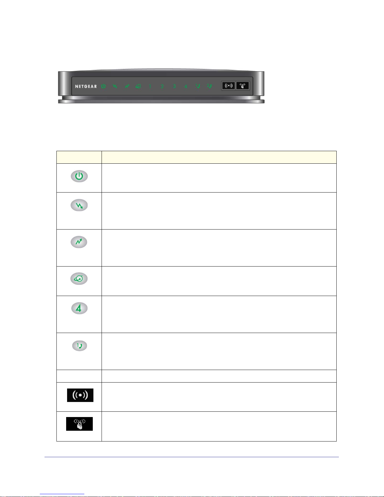
Gateway Front Panel
Figure 1. Gateway front view
You can use the LEDs to verify status and connections. The following table lists and
describes each LED and button on the front panel of the gateway..
LED Description
• Green. Power is supplied to the cable modem.
• Blinking. Power on self-test.
Power
Downstream
• Off: No power.
• Green solid. One or more downstream channels is locked.
• Green slow blink. The unit is scanning for a downstream channel.
• Green blink. Data is being transmitted or received.
• Off: No downstream channel is locked.
• Green solid. One or more upstream channels is locked.
• Green slow blink. The unit is scanning for an upstream channel.
Upstream
Internet
LAN (Ethernet)
Phone Port
Button Description
Wireless On/Off
• Green blink:. Data is being transmitted or received.
• Off:. No upstream channel is locked.
• Solid green. The cable modem is online.
• Blinking. The cable modem is synchronizing with the cable provider’s CMTS.
• Off. The cable modem is offline.
Green indicates 1,000 Mbps. Amber indicates 100/10 Mbps.
• Solid. An Ethernet device is connected and powered on.
• Blinking. Data is being transmitted or received on the Ethernet port.
• Off: No Ethernet device is detected on the Ethernet port.
• Green Solid. Registered with the Call Agent.
• Green Blink. There is an active call.
• Green Slow Blink. Phone is on-hook, registration with Call Agent is in progress.
• Off. No phones are connected to the phone port.
Turn the wireless radio in the gateway on and off. The wireless radio is on by default. The
LED located below this button indicates if the wireless radio is on or off.
Pushing this button opens a 2-minute window for the gateway to connect with other
WPS-enabled devices. For more information, about using the WPS method to implement
WPS
security, see the Push 'N' Connect (WPS) Wireless Setup on page 12
Connect to the Internet
6
Page 7
NETGEAR Wireless Cable Gateway
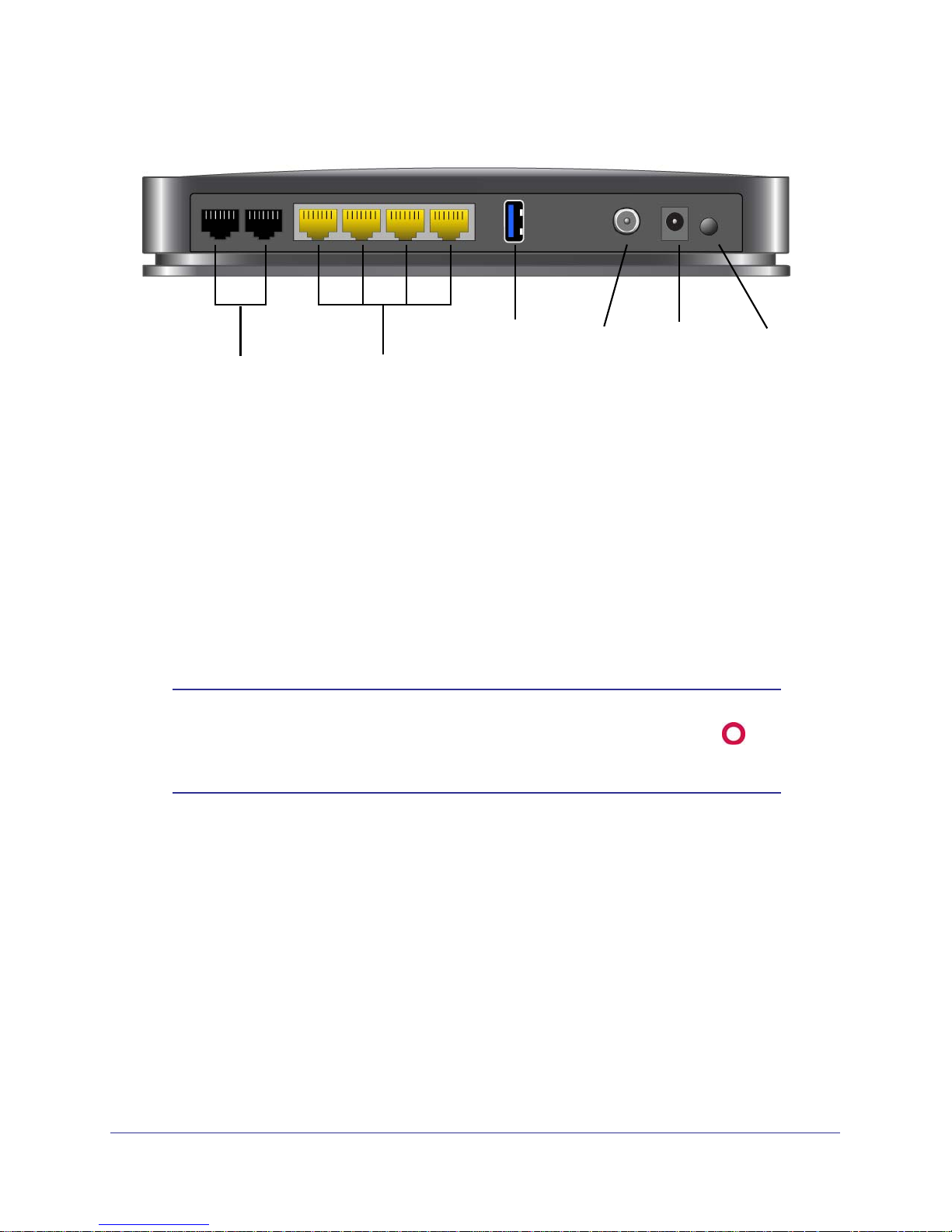
Gateway Rear Panel
Voice ports
Figure 2. Gateway rear panel
Ethernet LAN ports
USB
port
Coaxial
cable
connector
Power
adapter
input
Power On/Off
button
The rear panel includes the following connections, viewed from left to right:
• Two voice/phone ports. WIth VoIP service, connect one or two handsets to these ports.
• Four Gigabit-Ethernet LAN ports. Use these ports to connect local computers.
• USB port: The USB port is a USB host and can be used for connecting a USB printer.
Note: USB functionality is only available with future firmware upgrades.
• Power. Power adapter input.
• Power On/Off button.
Note: You can return the gateway to its factory settings. On the bottom of
the gateway, press and hold the Restore Factory Settings button
for over 7 seconds. The gateway resets, and returns to its factory
settings. See Factory Default Settings in Appendix A.
Install the Voice Gateway
Installation is the four-step process summarized here and described in the headings that
follow. Make sure you complete the installation in this order.
1. Check the Installation Requirements.
2. Cable the Gateway.
3. Log in to the Gateway.
4. Connect to the Internet.and VoIP.
After installation, set up the wireless connection as explained in Chapter 2, Wireless
Configuration.
Connect to the Internet
7
Page 8

NETGEAR Wireless Cable Gateway
Check the Installation Requirements
Check the requirements listed below before installing the gateway:
• Local Computer. During installation, you need a local computer to connect to the
gateway via Ethernet.
- This computer should be set up to access the cable modem Internet service.
- This computer must be set up to use DHCP to get its TCP/IP configuration from the
gateway.
• Cabling. Use a Category 5 (CAT5) cable such as the one provided with your gateway for
your LAN connections.
• Cable Modem Service. There must be active Data Over Cable Internet service provided
by cable modem account.
• Internet Service Provider (ISP) Configuration. Depending on how the ISP set up the
Internet account, you will need one or more of these configuration settings to connect the
gateway to the Internet:
- Host and Domain Names
- ISP Domain Name Server (DNS) Addresses
- Fixed or Static IP Address
• Computers on the Network. Each computer that will connect to the gateway must have
either an installed Ethernet Network Interface Card (NIC), or 802.11b/g/n wireless
adapter.
Cable the Gateway
To install the gateway, connect it to a computer by an Ethernet cable according to the
guidelines below.
Ethernet Connection
If you are connecting a computer to the gateway with an Ethernet cable, following these
instructions.
1. Turn off your computer.
2. Use the coaxial cable provided by your cable company to connect the wireless voice
gateway cable port to your cable line splitter or outlet.
3. Connect the LAN port (for example, LAN port 4) on the gateway to your computer with the
Ethernet cable included in the box.
4. Plug in the gateway and wait about 30 seconds for the lights to stop blinking.
5. Turn on your computer. If software usually logs you in to your Internet connection, do not run
that software or cancel it if it starts automatically.
Connect to the Internet
8
Page 9
6. Verify the following:
NETGEAR Wireless Cable Gateway
a. The power light
b. The Internet light
is lit after turning on the gateway.
is solid green, indicating a link has been established to the
cable network.
c. The LAN LED
is lit for the port where you connected the computer.
Log In to Your Gateway
You can log in to the gateway to view its settings. A link to the documentation is also available
in the gateway main menu.
Note: To connect to the gateway you must use a computer configured for
DHCP (most computers are).
When you have logged in, if you do not click Logout, the gateway waits for 5 minutes after no
activity before it automatically logs you out.
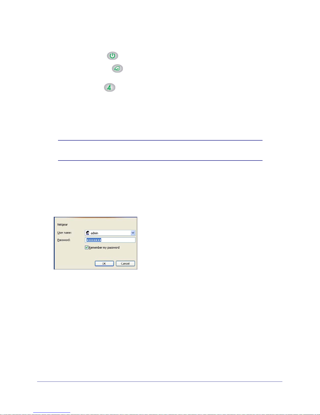
1. On the computer that is connected to the gateway with an Ethernet cable, type
http://192.168.1.1 in the address field of your Internet browser.
A login window opens.
2. Log in with the user name admin and its default password of password.
When you connect to the gateway the Gateway Status screen displays.
Connect to the Internet
9
Page 10
NETGEAR Wireless Cable Gateway
To view the gateway’s settings for the Internet connection, see the following section, View
the Gateway Status on page 10.
Connect to the Internet and VoIP
If you have VoIP service, connect the phone to Voice Port 1 . If your service includes a
second line, you can connect that phone to Voice Port 2.
View the Gateway Status
The Gateway Status screen shows the network configuration for the gateway. Select
Gateway Status from the main menu. The Network Configuration section is in the middle of
the page.
Connect to the Internet
10
Page 11

2. Wireless Configuration
This chapter describes how to use the Wireless Settings screens to add devices and to view and
change (if needed) your wireless network settings.
This chapter includes:
• Push 'N' Connect (WPS) Wireless Setup
• Basic Configuration
• MTA Configuration
• Wireless Configuration
• Wi-Fi Multimedia
2
11
Page 12

NETGEAR Wireless Cable Gateway
Connecting Devices
To wirelessly connect to the gateway, a computer or wireless device requires the same wireless
settings as the gateway.
• The default wireless network name (SSID) for the gateway is shown on the product label.
This product comes with a preconfigured Wi-Fi SSID and passphrase.
• By default the gateway works with WPA and WPA 2 wireless security. The default
passphrase is shown on the product label.
To use Push 'N' Connect (WPS), your wireless computers and equipment have to support WPS
technology.
Push 'N' Connect (WPS) Wireless Setup
Push 'N' Connect (WPS) can be a quick way to automatically set up your gateway’s wireless
network and set up your wireless computer to connect to it at the same time. WPS, also
called Wi-Fi Protected Setup, is a relatively new technology, so before you decide to use it,
check to make sure your wireless computers and devices support WPS. Look for the
symbol on all the computers that will connect wirelessly to the gateway.
If you do not see the symbol on all the computers that will connect to the wireless
network, then you should manually set up your network first (see Wireless Configuration ).
After that, you can still use WPS to set up the wireless connection for the computers that
support WPS.
Note: All WPS-capable products should be compatible with the gateway.
For more detailed information about the WPS standard, see
http://www.wi-fi.org).
To use Push 'N' Connect (WPS), your wireless computers and equipment must support WPS
technology. There are two Push 'N' Connect methods, Push Button and PIN (personal
identification number).
• Push Button. This is the preferred method.
• PIN described below.
WPS Button
You can use the WPS button to automatically set up wireless settings in your gateway and to
set up your wireless computer to connect to it.
1. Make sure you know how WPS works on your computer or wireless device. If it works
with WPS, it has a WPS utility and might also have a WPS button that you can press.
Wireless Configuration
12
Page 13

NETGEAR Wireless Cable Gateway
2. Select Add WPS Client and then click Next. The Add WPS Client screen displays:
Any computer or wireless device that wirelessly connects to the gateway is a client. After
it is added as a client, it will be able to automatically connect to the gateway.
3. Either click the
WPS button, or press the button on the front of the gateway.
• The WPS LED on the front of the gateway begins to blink.
• The gateway tries to communicate with the wireless computer or device for 2 minutes.
• If the Security Option in the Wireless Settings screen was set to Disabled, it is
automatically changed to WPA-PSK [TKIP] + WPA2-PSK [AES] including a random
wireless security password.
4. Go to the wireless computer, and run its WPS configuration utility. Follow the utility’s
instructions to click a WPS button.
When the computer connects to the wireless network, the gateway sends its SSID and
WPA-PSK or WPA2-PSK configuration to that computer.
5. On the computer that just joined the wireless network, make sure you can connect to the
Internet. You should see the gateway’s Internet LED blink, showing that its Internet
connection is in use.
PIN Connection
1. First, make sure you know how WPS works on your computer or wireless device. If it
works with WPS, it has a WPS utility. Use this utility to determine the PIN for your
wireless computer or device.
Wireless Configuration
13
Page 14
NETGEAR Wireless Cable Gateway
2. Select WPS Settings and then click Next. The Add WPS Client screen displays.
Any computer or wireless device that will wirelessly connect to the gateway is a client.
After it is added as a client, it will be able to automatically connect to the gateway.
3. Select the PIN radio button.
4. Type the PIN that you located in Step 1 in the Enter Client’s PIN field, and then click Next.
• The WPS LED on the front of the gateway begins to blink.
• The gateway tries to communicate with the wireless computer or device for 4 minutes.
• If the Security Option in the Wireless Settings screen was set to Disabled, it is
automatically changed to WPA-PSK (including a PSK security password).
When the computer connects to the wireless network, the gateway sends its SSID and
WPA-PSK or WPA2-PSK configuration to that computer.
5. On the computer that just joined the wireless network, make sure you can connect to the
Internet. You should see the gateway’s Internet LED blink, showing that its Internet
connection is in use.
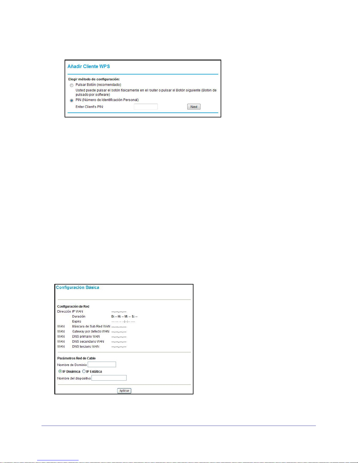
Basic Configuration
Select Configuration > Basic to configure and monitor your network configuration.
Network Configuration. The screeh shows the current network settings on the WAN side of
the gateway. If you are using dynamic IP addressing, this configuration has been assigned by
Wireless Configuration
14
Page 15

NETGEAR Wireless Cable Gateway
your ISP. If you are using static IP addressing, this setting matches the cable network that
follows.
Network Configuration Cable. You can define settings for the WAN side of your gateway in
this section.
Dynamic IP / Static IP. Select Dynamic IP If you want to get the settings dynamically
from your ISP. Select Static IP if you want to manually configure the network.
If you select Static IP, you have to set the following values.
• Static IP Address. Enter the WAN IP address of your gateway.
• Subnet Mask. Enter subbred mask the IP WAN.
• Default Gateway. Type the IP address of the default gateway.
• Primary DNS. Enter the IP address of primary server.
• Secondary DNS. Enter the IP address of secondary DNS.
• Tertiary DNS. Enter the IP address of the tertiary DNS.
• Device Name. Enter the name or alias for the router. You can find the name of the
router in Windows Vista and in the web browser for all Windows systems.
Click Apply when you are finished changing your settings.
Wireless Configuration
15
Page 16
NETGEAR Wireless Cable Gateway
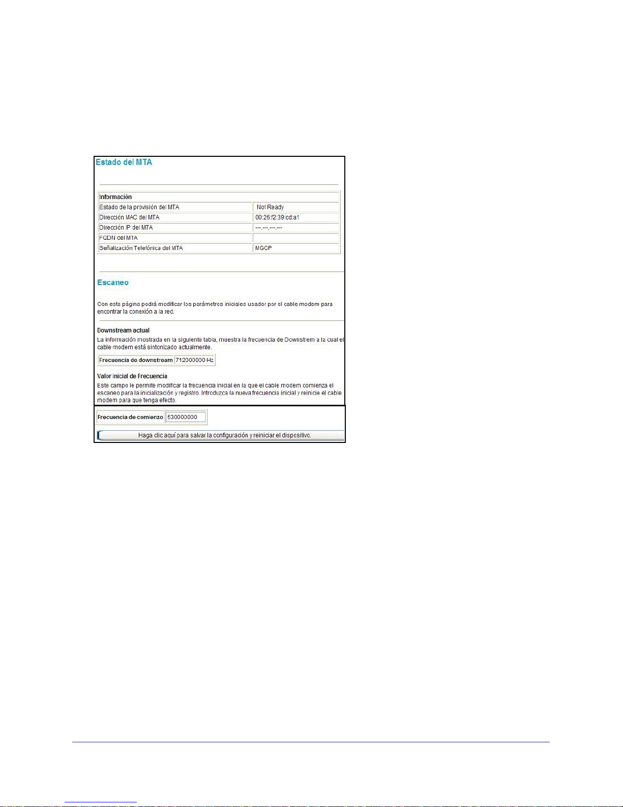
MTA Configuration
Select Configuration > MTA Status to display the Multimedia Terminal Adaptor (MTA) Status
screen. This page refreshes every 15 seconds to update the status.
MTA Provision Status. Shows which of your telephone lines are active and registered with
your service provider.
MTA MAC Address. The MAC address of the MTA interface.
MTA IP Address. The IP MTA address.
MTA FQDN. The fully qualified domain name of the MTA (only in the domain name).
MTA Telephony Signaling. The type of telephony signaling the MTA currently uses.
Scan.This page refreshes every 15 seconds to update the status
Current Downstream. The downstream frequency to which the cable modem is tuned.
Initial Value Frequency. The frequency at which the cable modem starts its scanning during
initialization and registration.
Wireless Configuration
16
Page 17
NETGEAR Wireless Cable Gateway
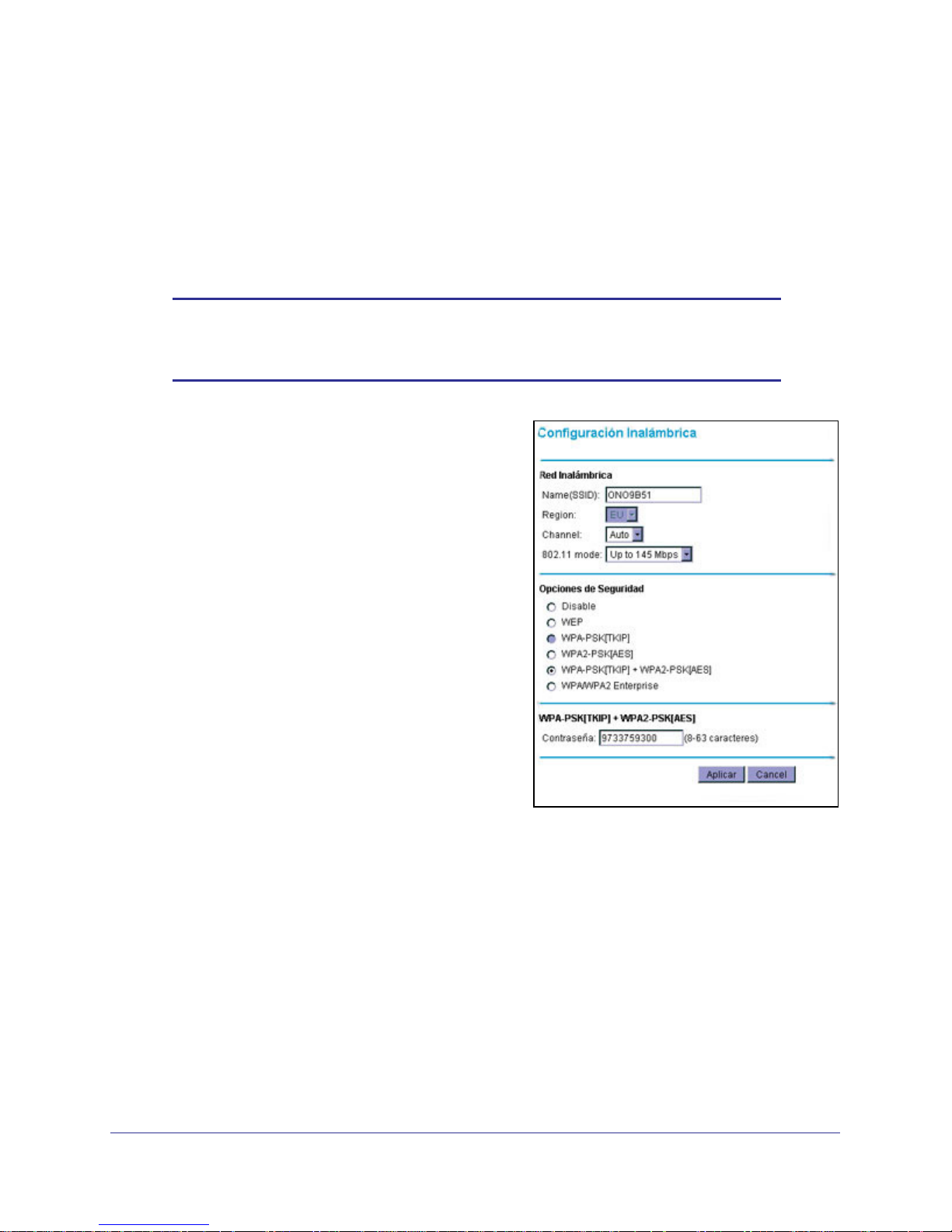
Wireless Configuration
You can manually configure the wireless settings and security for your gateway from the
Wireless Configuration screen.
1. If you are located near the gateway, use an Ethernet cable to connect your computer to
the gateway while you are changing the wireless settings.
Note: If you connect wirelessly to the gateway and then change its
wireless network name (SSID) or wireless security, you will be
disconnected after you click Apply.
2. Select Setup > Wireless Settings to display
this screen.
3. Specify the Wireless Network settings.
• Name (SSID). The name of the wireless
network.
• Region. The location where the gateway
will operate.
• Channel. The available channels depend
on the region. Some countries have laws
specifying which channels should be used.
• 802.11 Mode. This can is set to 145 Mbps
by default. For help with Security Options,
see the following sections.
4. If you made changes, click Apply so that they
take effect.
WPA or WPA2 Wireless Security
By default the gateway is set up to work with both WPA and WPA2 wireless security. (This
security option is already selected.) You can specify the Network Key, which works like a
password to access the wireless network.
Wireless Configuration
17
Page 18

NETGEAR Wireless Cable Gateway
1. In the Security Options section of the
Wireless Settings screen, leave the default
setting or
select one of the WPA settings:
• WPA-PSK. This setting provides the TKIP
encryption type and a pre-shared key
passphrase.
• WPA2-PSK. This setting provides the AES
encryption type and a pre-shared key
passphrase.
2. Depending on the WPA settings that you select,
enter the required information.
For WPA-PSK or WPA2-PSK, enter the
pre-shared key, which is a passphrase between 8 and 63 characters. This product comes
with a preconfigured WPA passphrase.
3. Click Apply to save your settings.
4. Configure your wireless computers with the same WPA2 or WPA settings as your gateway
so that you will be able to connect.
WEP Security
Note: By default, the gateway is set up to work with WPA and WPA2
wireless security, both of which are newer than WEP. Typically, the
only reason you might need to set up WEP would be to allow access
to older wireless computers or devices that cannot support WPA.
Wireless Configuration
18
Page 19

NETGEAR Wireless Cable Gateway
1. In the Security Options section of the Wireless
Settings screen, select the WEP radio button.
2. Select the Authentication from the drop-down
list.The default is Automatic.
3. Depending on the encryption strength that you
want, select one of these WEP Encryption
options:
• 64-bit encryption
• 128-bit encryption
4. Enter a Passphrase (recommended) or WEP
Keys:
• To use a passphrase and generate keys,
enter a passphrase and click Generate.
• To enter the keys, fill in the Key 1 through
Key 4 fields. Write down the keys and keep
them in a secure location.
- For 64-bit WEP, enter 10 hexadecimal
digits (any combination of 0–9 or A–F).
For 128-bit WEP, enter 26 hexadecimal digits.
- Select which key will be the default, which will be used to encrypt data
transmissions. The other keys can only be used to decrypt received data.
5. Click Apply to save your settings.
Configure your wireless computers with the same WEP settings as your gateway so that you will
be able to connect. If you entered the keys, you will need to type them exactly as you did when
you set up the gateway.
Wireless Configuration
19
Page 20

NETGEAR Wireless Cable Gateway
Wi-Fi Multimedia
You can use the Multimedia page to set up wireless multimedia Quality of Service (QoS).
1. Log in to the gateway as described in Log In to Your Gateway on page 9.
2. In the main menu, under Setup, select Wi-Fi Multimedia.
3. In the WMM Support field, select On to enable WMM.
4. In the No-Acknowledgement field, select Off or On to specify whether acknowledgement
(ACK) messages are used.
Usually, this field is set to Off. This might improve the efficiency of packet transmission. If
wireless communication quality is poor at your location (this could happen if there is a lot
of interference), set this field to On so that you are notified when a package is lost.
5. To conserve battery power in smaller devices that are connected to the gateway, set the
Power Save Support field to On.
6. Click Apply to save your settings.
Wireless Configuration
20
Page 21

3. Content Filtering
This chapter describes how to use content filtering s for the gateway. This chapter includes:
• View or Email Logs
• Block Keywords, Sites, and Services
• Services
3
21
Page 22

NETGEAR Wireless Cable Gateway
View or Email Logs
Your gateway logs security-related events such as Denial of Service (DoS) attacks, hacker
probes, and administrator logins, based on the settings on the Logs screen. If you set up
content filtering on the Block Sites screen, you can also log when someone on your network
tried to access a blocked site. You can specify which events are logged and you can send the
logs to the specified email address.
1. Select Content Filtering >
Logs.
2. To use email, fill in the Contact
Email Address and SMTP
Server Name fields.
3. Select the Enable check box for
E-mail Alerts.
4. Click Apply so your changes
take effect.
5. To email the log now, click E-mail
Log.
To delete all log entries. click Clear Log. To see the most recent entries, click Refresh.
Block Keywords, Sites, and Services
With its content filtering feature, the gateway prevents objectionable content from reaching
your computers. The gateway allows you to control access to Internet content by screening
for keywords within Web addresses. It can also block access to all sites except those that are
explicitly allowed. For example, you can set up the gateway to do the following:
• Block access from to Internet locations that contain keywords that you specify.
• Block access to websites that you specify as off-limits.
• Allow access to only websites that you specify as allowed.
Block Keywords and Domains
The gateway allows you to restrict access to Internet content based on functions such as
Web address keywords and Web domains. A domain name is the name of a particular
website. For example, for the address www.NETGEAR.com, the domain name is
NETGEAR.com.
1. Select Content Filtering > Block Sites.
Content Filtering
22
Page 23

NETGEAR Wireless Cable Gateway
2. To block keywords, select the Keyword
Blocking Enable check box. Type the keyword
and then click Add Keyword.
• If the keyword XXX is specified, the URL
www.zzzyyqq.com/xxx.html is blocked.
• If the keyword .com is specified, only
websites with other domain suffixes (such
as .edu, .org, or .gov) can be viewed.
• Enter the keyword “.” to block all Internet
browsing access.
• To remove a keyword from the Keyword
List, select it, and click Remove Keyword.
3. To block domains, select the Domain Blocking
Enable check box. Enter a domain and click Add
Domain.
• If the domain www.zzzyyqq.com is
specified, the URL
<http://www.zzzyyqq.com/xxx.html> is
blocked, along with all other URLs in the
www.zzzyyqq.com site.
• To remove a domain from the Domain List, select the domain, and then click Remove
Domain.
4. Click Apply to save your settings.
Content Filtering
23
Page 24

NETGEAR Wireless Cable Gateway
Services
You can use the Services screen to disable certain gateway features.
1. Select Content Filtering > Services.
2. To disable a feature, clear its check box.
3. Click Apply for your changes to take effect.
The following Services are available in this screen:
• Firewall Features. The gateway performs
Stateful Packet Inspection (SPI) and protect
against Denial of Service (DoS) attacks.
• IPSec Pass-Through. IPSec traffic is forwarded.
If you clear this check box then this traffic will be
blocked.
• PPTP Pass-Through. PPTP traffic is forwarded.
If you clear this check box then this traffic will be
blocked.
• Multicast. The gateway can pass multicasting
streams through the firewall.
• Port Scan Detection. When enabled, the
gateway can respond to Internet-based port
scans.
• IP Flood Detection. Allows the is gateway to block malicious devices that are attempting
to flood devices.
• You can use the Web Features to set certain Web-oriented cookies, java scripts, and
pop-up windows to be blocked by the firewall.
Content Filtering
24
Page 25

4. Manage Your Network
This chapter describes how to perform network management tasks with your gateway. When
you log in to the gateway (see Log In to Your Gateway on page 9), these tasks are grouped
under Maintenance.
This chapter includes:
• Gateway Status
• Connection Status
• Change Passwords
• Back Up and Restore Your Settings
• Event Log
• Diagnostic Ping Utility
4
25
Page 26

NETGEAR Wireless Cable Gateway
Gateway Status
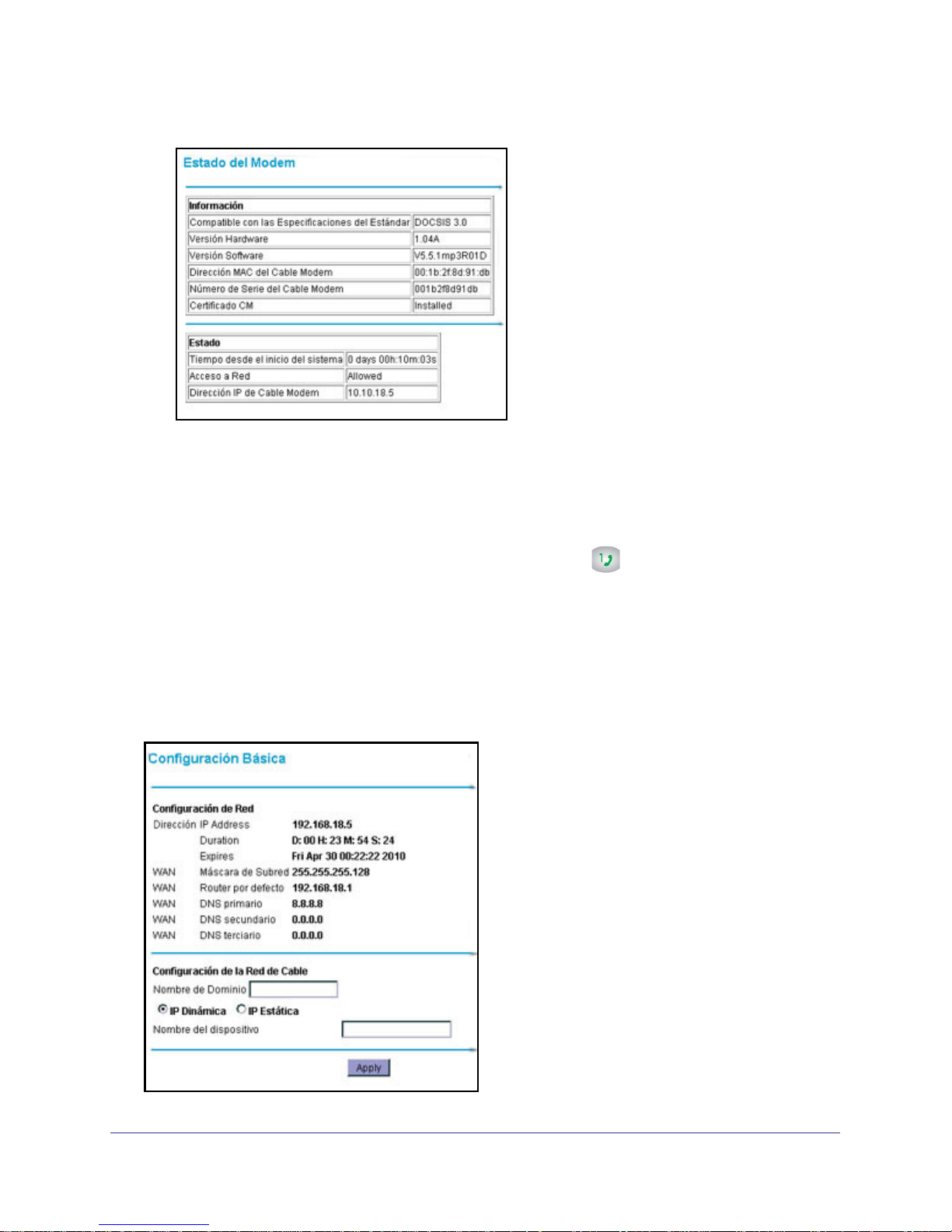
Select Maintenance > Gateway Status to see hardware and firmware details about the
gateway and basic status information.
The following table describes the fields displayed in this screen.
Information:
Modem Status Field Description
Standard Specification
Compliant
Hardware Version The hardware version of the gateway.
Software Version The version of firmware currently running on the gateway.
Cable MAC Address The MAC address used by the cable modem port of the gateway. This MAC
Device MAC address The MAC address used by the cable modem.
Cable Modem Serial number The serial number of the gateway hardware.
CM Certificate If the cable modem certificate is Installed, it is possible for the service provider to
DOCSIS 3.0
address may need to be registered with your cable service provider.
upgrade your Data Over Cable service securely.
Status:
Modem Status Field Description
System Up Time Time since the last boot up.
Network Access Shows whether traffic can be forwarded from the LAN to the network
Cable Modem IP Address The current Internet IP address. If assigned dynamically and not connected to
the Internet, this field is blank.
Manage Your Network
26
Page 27

NETGEAR Wireless Cable Gateway
Connection Status
Select Maintenance > Connection Status to view connection status information.
Use the Connection screen to track the gateway’s initialization procedure, and to get details
about the downstream and upstream cable channel. The time is displayed after the gateway
is initialized.
The gateway automatically goes through the following steps in the provisioning process:
• Scan and lock the downstream frequency, and then link back in upstream direction.
• Obtain an IP address for the gateway itself. Then the gateway assigns an IP address for
the connected PC.
• Connect to the Internet.
Manage Your Network
27
Page 28

NETGEAR Wireless Cable Gateway
Change Passwords
For security reasons, the gateway has its own user names and passwords. NETGEAR
recommends that you change the default passwords to more secure passwords. The ideal
passwords should contain no dictionary words from any language, and should be a mixture of
both upper and lower case letters, numbers, and symbols. Your passwords can be up to 30
characters.
Select Maintenance > Set Password.
1.
2. To change the password, enter the new password twice.
3. Click Apply to save your changes.
Note: After changing the password, you will be required to log in again to
continue the configuration. If you have backed up the gateway
settings previously, you should do a new backup so that the saved
settings file includes the new password.
Back Up and Restore Your Settings
The configuration settings of the gateway are stored in a configuration file in the gateway.
1. Select Maintenance > Backup Settings.
2. You can save the current configuration settings or restore saved settings:
• To save the current configuration settings, click Back Up.
Manage Your Network
28
Page 29

NETGEAR Wireless Cable Gateway
• To restore the saved configuration settings from a backup file, click Browse, locate
and select the previously saved backup file. Then click Restore.
A message notifies you when the gateway has been restored to previous settings. Then, the
gateway restarts, which takes about one minute.
Note: When restoring configuration settings, do not interrupt the process
by going online, turning off the gateway, or shutting down the
computer.
Event Log
The gateway logs security-related events such as denied incoming service requests and
hacker probes.
1. Select Maintenance > Event Log.
2. To clear the log, click Clear Log; to refresh the log, click Refresh.
Manage Your Network
29
Page 30

NETGEAR Wireless Cable Gateway
Diagnostic Ping Utility
1. Select Maintenance > Diagnostics.
2. To start a ping test, enter the IP address in the Diagnostics screen, and click the Ping
button. The Ping Results are displayed:
3. To return to the Diagnostics screen and stop the test, click Back and then click Abort Test.
Manage Your Network
30
Page 31

5. Advanced Settings
This chapter describes how to customize your network through the advanced settings on your
gateway. When you log in to the gateway (see Log In to Your Gateway on page 9), these tasks
are grouped under Advanced.
This chapter includes:
• Wireless Settings
• MAC Filtering .
• Port Blocking .
• Port Forwarding .
• Port Triggering .
• DMZ Host .
• LAN IP Setup .
• Remote Management .
• Universal Plug and Play (UPnP) .
5
31
Page 32

NETGEAR Wireless Cable Gateway
Wireless Settings
Select Advanced > Wireless Settings to display the following screen where you can
configure the wireless radio settings, and other advanced settings:
The following table describes the fields in the Advanced Wireless Settings screen.
Advanced Wireless Settings Description
Wireless Access
Point
Advanced
Configuration
WPS Settings Router’s PIN The PIN that WPS clients use to connect to the
Wireless Card
Access List
Enable Wireless Access Point By default this checkbox is selected so that the
gateway works as a wireless access point. You can
turn off the wireless radio to disable access through
this device. This can be helpful for configuration,
network tuning, or troubleshooting activities.
Enable SSID Broadcast By default this checkbox is selected so that the
gateway broadcasts it’s Wi-Fi network name (SSID)
so devices can find it. Deselect this checkbox if you
do not want wireless devices to find this gateway
unless they have the same SSID.
• Fragmentation Threshold
• CTS/RTS Threshold
• Preamble Mode
Set up Access List Access control is disabled by default so that any
The default settings for these fields usually work fine.
Change them only if you have a specific reason for
doing so.
gateway using the PIN method.
computer that is configured with the correct SSID
can connect. For information about access control,
see the following section.
Advanced Settings
32
Page 33

NETGEAR Wireless Cable Gateway
MAC Filtering
By default, the gateway allows any connected PC to access the Internet through. The MAC
Filtering screen lets you block specific computers, based on their MAC address, from access
to the Internet on selected days and times.
Block a Computer
1. Select Advanced > MAC Filtering.
The Trusted Devices table shows
computers that have access to the Internet
through the gateway. Click Refresh to
update the Trusted Devices table.
2. In the Add MAC Filter table, you can use
either of these methods to specify
computers to block:
• If the computer is in the Trusted
Devices table, click its radio button.
The MAC address will be added into
the Add MAC Filter table.
• Fill in the Device Name and MAC
address fields.
3. Click Add.
The MAC Filter List Enable checkbox is
automatically selected for that computer.
4. Select the days and times to block the
computer:
• Day(s) to Block. Select the days to block the computer selected in the MAC Filter
List. The default is Everyday.
• Time of Day to Block. You can specify the time of day to block the computer. The
default is All Day. Be sure that you clear the All Day checkbox if you want to enter
specific times. The selected period applies to each day that you selected.
5. Click Apply to save your settings.
6. Repeat these steps for all computers that you want to block.
Unblock A Computer
• To stop blocking a computer, select it from the MAC Filter List field, and then clear its
Enable check box. This leaves the computer in the list but ensures that it is not
blocked.
• To remove a computer from the list, select it from the MAC Filter List field, and then
click Delete.
Advanced Settings
33
Page 34

NETGEAR Wireless Cable Gateway
Port Blocking
You can use port blocking to block outbound traffic on specific ports. Outbound traffic rules
control access to outside resources from local users.The default rule is to allow all access
from the LAN side to the outside. You can use port blocking to add predefined or custom rules
to specify exceptions to the default rule.
Note: Any outbound traffic that is not blocked by rules that you have
created is allowed by the default rule.
1. Select Advanced > Port Blocking.
2. In the Services field, select a service from
the drop-down list. (For example, FTP,
which uses TCP ports 20 and 21.)
3. To add a custom rule that is not in the list of
services, specify these settings in the Add
Custom Rules table:
• Name. Enter a name for the service.
• Start Port. Enter the start port for the
service.
• End Port.Enter the end port for the
service.
• Protocol. Select the protocol for the ports:
- TCP. Select TCP only.
- UDP. Select UDP only.
- Both. Select both TCP and UDP.
• Local IP Address. Complete the local IP address for the computer that is using the
service.
4. Perform one of the following actions:
• Click Add to save your settings. The Active Filters table now displays the list of ports
that are currently forwarded.
• To delete a service, select the radio button in the Active Filters table for the service
that you want to delete, and then click Delete.
• To reset the selection in the Services drop-down list and to clear all the fields in the
Add Custom Rules table, click Reset.
Advanced Settings
34
Page 35

NETGEAR Wireless Cable Gateway
Port Forwarding
A firewall has default rules for inbound traffic (WAN to LAN) and for outbound traffic. Port
forwarding affects the inbound rules. These rules restrict access from outsiders. By default,
the gateway blocks access from outside except responses to requests from the LAN side.
You can use port forwarding to add rules to specify exceptions to the default rule.
Because the gateway uses Network Address Translation (NAT), your network presents only
one IP address to the Internet, and outside users cannot directly address any of your local
computers. However, by defining an inbound rule you can make a local server (for example,
a web server or game server) or computer visible and available to the Internet. The rule tells
the Gateway to direct inbound traffic for a particular service to one local server or computer
based on the destination port number. This is also known as port forwarding.
Some residential broadband ISPs do not allow you to run server processes (such as a Web
or FTP server) from your location. Your ISP might check for servers and suspend your
account if it finds active services at your location. See your ISP’s Acceptable Use policy.
1. Select Advanced > Port Forwarding.
2. In the Service field, select a service from
the drop-down list. (For example, FTP,
which uses TCP ports 20 and 21.)
3. To add a custom rule that is not in the list
of services, specify these settings in the
Add Custom Rules table:
• Name. Enter a name for the service.
• Start Port. Enter the start port for the
service.
• End Port. Enter the end port for the
service.
• Protocol. Select the protocol for the
ports:
- TCP. Select TCP only.
- UDP. Select UDP only.
- Both. Select both TCP and UDP.
• Local IP Address. Complete the local IP address for the computer that is using the
service.
4. Perform one of these actions:
• Click Add. The Active Forwarding Rules table displays the list of forwarded ports.
• To delete a service, select the radio button in the Active Forwarding Rules table for
the service that you want to delete, and then click Delete.
• To reset the selection in the Services field and to clear all the fields in the Add Custom
Rules table, click Reset.
Advanced Settings
35
Page 36

NETGEAR Wireless Cable Gateway
Considerations for Port Forwarding
• If the IP address of the local server PC is assigned by DHCP, it might change when the
PC is rebooted. To avoid this, you can assign a static IP address to your server outside
the range that is assigned by DHCP, but in the same subnet as your LAN. By default, the
IP addresses from 192.168.1.2 through 192.168.1.9 are reserved for this purpose.
• Local PCs must access the local server using the PCs’ local LAN address
(192.168.1.XXX, by default). Attempts by local PCs to access the server using the
external WAN IP address will fail.
• Port forwarding opens holes in your firewall. Only enable ports that are necessary.
Port Triggering
Port triggering is an advanced feature that you can use to allow gaming and other Internet
applications that would otherwise be blocked by the firewall. You must know the port numbers
that are used by the application. Port triggering operates as follows:
1. A computer makes an outgoing connection using a port number defined in the Port
Triggering table.
2. The gateway records this connection, opens the incoming port or ports associated with this
entry in the Port Triggering List, and associates them with the PC.
3. The remote system receives the PCs request, and responds using a different port number.
4. The gateway matches the response to the previous request, and forwards the response to
the PC. (Without port triggering, this response would be treated as a new connection request
rather than a response. As such, it would be handled in accordance with the port forwarding
rules.)
Note: Only one computer at a time can use port triggering. After a
computer finishes using a port triggering application, there is a short
time-out period before the application can be used by another PC.
Advanced Settings
36
Page 37

NETGEAR Wireless Cable Gateway
1. Select Advanced > Port Triggering.
2. For each port trigger, enter the settings in the Port Trigger List:
• Trigger Range. To specify the range of outgoing ports that will be monitored to trigger
the incoming port forwarding rule, enter the Start Port and End Port.
• Target Range. To specify the range of incoming ports that will be opened when
triggered, enter the Start Port and End Port.
• Protocol. Select the protocol for the ports:
3. Select the Enable checkbox for the port trigger.
4. Perform one of the following actions:
• Click Apply to save your settings and activate the port triggers.
• To remove a port trigger, select it’s radio button and click Delete.
• To return all trigger and target ranges to zero, click Reset.
Advanced Settings
37
Page 38

NETGEAR Wireless Cable Gateway
DMZ Host
You can use the DMZ Host screen to set up a default DMZ computer. Specifying a default
DMZ computer allows you to set up a PC that is available to anyone on the Internet for
services that you have not defined. There are security issues with doing this, so only set up
the DMZ host if you are willing to risk open access. If you do not define a DMZ host the
gateway discards any undefined service requests.
1. Select Advanced > DMZ Host.
2. If desired, select the Respond to Ping on WAN Port checkbox.
3. Type the last digit(s) of the IP address in the DMZ Address field.
4. Click Apply.
LAN IP Setup
The LAN IP screen allows you to configure LAN services such as the IP address of the
gateway and DHCP. The TCP/IP and DHCP default values work fine in most cases.
Note: If you disable the DHCP server, you will need to assign to your
computer a static IP address to reconnect to the gateway and enable
the DHCP server again.
Advanced Settings
38
Page 39

NETGEAR Wireless Cable Gateway
1. Select Advanced > LAN IP.
2. Specify these settings:
• LAN IP Address. The factory default
setting is 192.168.1.1.
• Subnet Mask. The network number
portion of an IP address. Unless you are
implementing subnetting, use
255.255.255.0 as the subnet mask.
• DHCP Server: The Yes radio button is
selected by default so the gateway acts
as a DHCP server, providing the TCP/IP
configuration for all the computers
connected to it.
If you will assign IP addresses manually,
or you have another DHCP server on
your network, select the No radio button.
• Starting IP Address and Ending IP
Address. These fields specify the range
in the IP address pool.
• Max Users. The maximum number of
users on the network.
• DHCP Lease. See the following section,
Reserving an IP Address for DHCP Use .
3. Click Apply to save your LAN settings
Reserving an IP Address for DHCP Use
To reserve an IP address for DHCP use, enter the DHCP server reservation settings for the
private LAN under DHCP Reservation Lease Info in the LAN Setup screen.
1. Enter the MAC address of the computer for which you want to reserve an IP address.
2. Enter the permanent IP address for the computer.
3. Click Add to save your settings.
The MAC address and IP address are displayed in the DHCP Client Lease Info table. The
current system time is also displayed.
To delete an IP address from the DHCP Client Lease Info table:
1. In the DHCP Client Lease Info table, click the radio button for the MAC and IP address
that you want to remove.
2. Click Delete to remove the information for the selected MAC and IP address from the DHCP
Client Lease Info table.
To remove all information from the DHCP Client Lease Info table, click Clear DHCP
Leases.
Advanced Settings
39
Page 40

NETGEAR Wireless Cable Gateway
Remote Management
With remote management, you can allow a user or users on the Internet to configure,
upgrade, and check the status of the gateway.
Note: Use very secure passwords if you enable remote management.
Passwords should contain no dictionary words from any language,
and should be a mixture of letters (both upper and lower case),
numbers, and symbols. Your password can be up to 16 characters.
To manage this gateway through the Internet, you need its public IP Address, as seen from
the Internet. This public IP address is allocated by your ISP. But if your ISP account uses a
dynamic IP address, the address can change each time you connect to your ISP. There are
two solutions to this problem:
• Have your ISP allocate you a fixed IP address.
• Use the DDNS (Dynamic DNS) feature so you can connect using a domain name, rather
than an IP address.
1. Select Advanced > Remote Management.
2. Select one of the Allow Remote
Management check boxes.
3. Fill in the Remote User Name and
Remote Password fields.
4. Specify the port numbers to access the
gateway remotely in your browser when
you connect. To specify the port
numbers:
a. From a remote location, start a
browser.
b. In the Address or Location field,
enter the Internet IP address of
this gateway (NOT the LAN IP
address), followed by a colon and
the port number, as follows:
http://ip_address:pn ||
https://ip_address:pn
where: ip_address is the Internet
IP address of this gateway.
pn is the port number assigned on
this screen.
Advanced Settings
40
Page 41

NETGEAR Wireless Cable Gateway
c. You are prompted for the password for this gateway.
5. If you want the ability to reset to factory default settings remotely, and then log in again
remotely, select the Allow Remote management after Factory Default Reset checkbox.
6. Click Apply to save your changes.
Table 1.
Remote Management
Settings
Allow Remote Management
(HTTP/HTTPS) CM interface
Allow Remote Management
(HTTP/HTTPS) CM interface
Remote User Name and
Remote Password
Port Number fields Web browser access normally uses the standard HTTP service port 80.
Revert to factory default
settings
IP Address to connect this
device
Description
If selected, remote management is enabled, and connection from the
Internet to this gateway with HTTP and HTTPS is possible. The correct port
number must be used when connecting
If selected, remote management is enabled, and connection from the
Internet to this gateway with HTTP and HTTPS is possible.
Enter the User Name and Password that will be used from the remote PC to
manage the gateway. Use a very secure password.
NETGEAR recommends that you use a different port number for remote
management, as using port 80 will prevent the use of a Web Server on your
LAN, and can be more readily discovered by hackers. Use the default
(8080) or choose a port number between 1 and 65535.
Allow Remote management after Factory Default Reset
The gateway’s public IP address so you can manage this gateway from the
Internet. Note that if your ISP account uses a dynamic IP address, this value
changes each time you connect to your ISP. You can either request your IP
allocate a fixed IP address to you or use the Dynamic DNS (DDNS) feature
to connect with a domain name instead of an IP address.
Advanced Settings
41
Page 42

NETGEAR Wireless Cable Gateway
Universal Plug and Play (UPnP)
Universal Plug and Play (UPnP) helps devices, such as Internet appliances and computers,
access the network and connect to other devices as needed. UPnP devices can
automatically discover the services from other registered UPnP devices on the network. With
UPnP you can specify:
• Advertisement Period. This specifies how often the gateway broadcasts its UPnP
information. The default is 30 minutes. Lower numbers ensure that control points
have current device status at the expense of additional network traffic. Larger
numbers may compromise the freshness of the device status but can significantly
reduce network traffic.
• Advertisement Time to Live. The time to live for the advertisement, measured in
hops (steps) for each UPnP packet that is sent. A hop is the number of steps that are
allowed to propagate for each UPnP advertisement before it disappears. The number
of hops can range from 1 to 255. The default value for the advertisement time to live is
4 hops, which should be fine for most home networks. If you notice that some devices
are not being updated or reached correctly, you might need to increase this value
slightly.
1. Select Advanced > UPnP.
2. Select the Turn UPnP On check box. The default setting is disabled, which prevents the
gateway from allowing any device to automatically control of its the resources, such as port
forwarding.
3. Fill in the Advertisement Period and Advertisement Time to Live fields.
The UPnP Portmap Table displays the IP address of each UPnP device that is currently
accessing the gateway and which internal and external ports of the gateway were opened
by that device. The UPnP Portmap Table also displays the protocol for the port that was
opened and if that port is still active for each IP address.
4. Perform one of the following actions:
• Click Apply to save your settings.
• Click Cancel to disregard any unsaved changes.
• Click Refresh to update the UPnP Portmap Table and to show the active ports that
are currently opened by UPnP devices.
Advanced Settings
42
Page 43

6. Troubleshooting
This chapter gives information about troubleshooting your NETGEAR Wireless Cable Gateway.
For the common problems listed, go to the section indicated.
• Have I connected the gateway correctly?
Go to Basic Functions on page 44.
• I cannot access the gateway configuration with my browser.
Go to Connect to the Main Menu on page 45.
• I have configured the gateway but I cannot access the Internet.
Go to Troubleshoot the ISP Connection on page 46.
• I cannot remember the gateway’s configuration password or I want to clear the
configuration and start over again.
Go to Factory Default Settings in Appendix A.
6
Tip: NETGEAR provides helpful articles, documentation, and the latest
software updates at
http://www.netgear.com/support.
43
Page 44

NETGEAR Wireless Cable Gateway
Basic Functions
After you have turned on power to the gateway, you should do the following:
1. Check to see that the Power LED is on.
2. Check that the numbered Ethernet LEDs come on momentarily.
3. After a few seconds, check that the local port link LEDs are lit for any local ports that are
connected.
If any of these conditions does not occur, refer to the appropriate following section.
Using LEDs to Troubleshoot
The following table provides help when using the LEDs for troubleshooting.
LED Behavior Action
All LEDS are off when the gateway
is plugged in.
All LEDs Stay On • Clear the gateway’s configuration to factory defaults. This will set the
LAN LED is off for a port with an
Ethernet connection.
Internet LED is off and the
gateway is connected to the cable
television cable.
Make sure that the power cord is properly connected to your gateway
and that the power supply adapter is properly connected to a
functioning power outlet.
Check that you are using the 12VDC power adapter supplied by
NETGEAR for this product.
If the error persists, you have a hardware problem and should contact
technical support.
gateway’s IP address to 192.168.1.1. See Factory Default Settings in
Appendix A.
• If the error persists, you might have a hardware problem and should
contact technical support.
• Make sure that the Ethernet cable connections are secure at the
gateway and at the hub or PC.
• Make sure that power is turned on to the connected hub or PC.
• Be sure you are using the correct cable.
• Make sure that the coaxial cable connections are secure at the
gateway and at the wall jack.
• Make sure that your cable internet service has been provisioned by
your cable service provider. Your provider should verify that the
signal quality is good enough for cable modem service.
• Remove any excessive splitters you may have on your cable line. It
may be necessary to run a “home run” back to the point where the
cable enters your home.
Troubleshooting
44
Page 45

NETGEAR Wireless Cable Gateway
Connect to the Main Menu
If you are unable to access the gateway’s main menu from a computer on your local network,
check the following:
• Check the Ethernet connection between the computer and the gateway as described in
the previous section.
• Make sure that your PC’s IP address is on the same subnet as the gateway. If you are
using the recommended addressing scheme, your PC’s address should be in the range
of 192.168.1.2 to 192.168.0.254.
Note: If your PC’s IP address is shown as 169.254.x.x:
Recent versions of Windows and MacOS will generate and assign
an IP address if the computer cannot reach a DHCP server. These
auto-generated addresses are in the range of 169.254.x.x. If your IP
address is in this range, check the connection from the PC to the
gateway and reboot your PC.
• If your gateway’s IP address has been changed and you don’t know the current IP
address, clear the gateway’s configuration to factory defaults. This will set the gateway’s
IP address to 192.168.1.1. This procedure is explained in
Factory Default Settings in
Appendix A.
• Make sure your browser has Java, JavaScript, or ActiveX enabled. If you are using
Internet Explorer, click Refresh to make sure that the Java applet is loaded.
• Try quitting the browser and launching it again.
• Make sure you are using the correct login information. The gateway user name admin is
lower-case (Caps Lock should be off). The default password of password.
If the gateway does not save changes you have made, check the following:
• When entering configuration settings, be sure to click the Apply button before moving to
another screen, or your changes are lost.
• Click the Refresh or Reload button in the Web browser. The changes may have occurred,
but the Web browser may be caching the old configuration.
Troubleshooting
45
Page 46

NETGEAR Wireless Cable Gateway
Troubleshoot the ISP Connection
If your gateway is unable to access the Internet and your Cable Link LED is on, you may
need to register the cable MAC address and/or device MAC address of you gateway with
your cable service provider.
Additionally, your PC may not have the gateway configured as its TCP/IP gateway. If your PC
obtains its information from the gateway by DHCP, reboot the PC and verify the gateway
address.
Troubleshoot a TCP/IP Network with The Ping Utility
Most TCP/IP terminal devices and routers contain a ping utility that sends an echo request
packet to the designated device. The device responds with an echo reply. Troubleshooting a
TCP/IP network is made easier by using the ping utility in your PC or workstation.
Test the LAN Path to Your Gateway
You can use ping to verify that the LAN path to your gateway is set up correctly.
To ping the gateway from a PC running Windows 95 or later:
1. From the Windows toolbar, click on the Start button and select Run.
2. In the field provided, type Ping followed by the IP address of the gateway, as in this
example:
ping 192.168.1.1
3. Click OK.
You should see a message like this one:
Pinging <IP address> with 32 bytes of data
If the path is working, you see this message:
Reply from < IP address >: bytes=32 time=NN ms TTL=xxx
If the path is not working, you see this message:
Request timed out
If the path is not working correctly, you could have one of the following problems:
• Wrong physical connections.
- Make sure the LAN port LED is on. If the LED is off, see Using LEDs to
Troubleshoot on page 44.
- Check that the corresponding Link LEDs are on for your network interface card
and for the hub ports (if any) that are connected to your workstation and gateway.
Troubleshooting
46
Page 47

NETGEAR Wireless Cable Gateway
• Wrong network configuration.
- Verify that the Ethernet card driver software and TCP/IP software are both
installed and configured on your PC or workstation.
- Verify that the IP address for your gateway and your workstation are correct and
that the addresses are on the same subnet.
Test the Path from Your PC to a Remote Device
After verifying that the LAN path works correctly, test the path from your PC to a remote
device. From the Windows run menu, type:
PING -n 10 <IP address>
where <IP address> is the IP address of a remote device such as your ISP’s DNS server.
If the path is functioning correctly, replies as in the previous section are displayed. If you do
not receive replies:
• Check that your PC has the IP address of your gateway listed as the default gateway. If
the IP configuration of your PC is assigned by DHCP, this information will not be visible in
your PC’s Network Control Panel. Verify that the IP address of the gateway is listed as
the default gateway.
• Check to see that the network address of your PC (the portion of the IP address specified
by the netmask) is different from the network address of the remote device.
• Check that your Cable Link LED is on.
• If your ISP assigned a host name to your PC, enter that host name as the Account Name
in the Basic Settings screen.
Wireless Performance and Gateway Location
The range of your wireless connection can vary significantly based on the physical placement
of the gateway. The latency, data throughput performance, and notebook power consumption
of wireless adapters also vary depending on your configuration choices.
For best results, place your gateway according to the following guidelines:
• Near the center of the area in which your computers will operate.
• In an elevated location such as a high shelf where the wirelessly connected PCs have
line-of-sight access (even if through walls).
• Away from sources of interference, such as PCs, microwave ovens, and 2.4 GHz
cordless phones.
• Away from large metal surfaces.
• Put the antenna in a vertical position to provide the best side-to-side coverage. Put
the antenna in a horizontal position to provide the best up-and-down coverage.
Troubleshooting
47
Page 48

NETGEAR Wireless Cable Gateway
• To reduce interference when using more than one access point, NETGEAR
recommends using 5 channel spacing between adjacent access points (for example,
use Channels 1 and 6, or 6 and 11).
The time it takes to establish a wireless connection can vary depending on both your security
settings and the gateway location. WEP connections can take slightly longer to establish.
Also, WEP encryption can consume more battery power on a notebook computer.
Troubleshooting
48
Page 49

A. Technical Specifications
This chapter includes:
• Factory Default Settings
• Technical Specifications
A
49
Page 50

NETGEAR Wireless Cable Gateway
Factory Default Settings
You can return the gateway to its factory settings. On the bottom of the gateway, press and
hold the Restore Factory Settings button for over 7 seconds. The gateway resets, and
returns to its factory settings.
shown in the following table.
Factory Default Settings
Gateway Login User login URL http://192.168.1.1
Your device will return to the factory configuration settings
User name and password (case
sensitive)
Local Network
(LAN)
Firewall Inbound communication from the
Internet
connection
LAN IP 192.168.1.1
Subnet mask 255.255.255.0
DHCP server Enabled
DHCP starting IP address 192.168.1.2
DHCP Ending IP address 192.168.1.254
Internet
Outbound communication to the
Internet
Source MAC filtering Disabled
WAN MAC address Use default hardware address
WAN MTU size 1500
admin/password
Disabled (except traffic on port 80, the http port)
Enabled (all)
Technical Specifications
50
Page 51

NETGEAR Wireless Cable Gateway
Factory Default Settings (Continued)
Wireless Wireless communication Enabled
SSID name As shown on the product label.
Security WPA/WPA2
Broadcast SSID Enabled
Transmission speed Auto
Country/region Depends on the country where the product is sold.
RF channel Auto
Operating mode n, g, and b
Data rate Best
Output power Full
Access point Enabled
Authentication type Open System
Wireless card access list All wireless stations allowed
1. Maximum Wireless signal rate derived from IEEE Standard 802.11 specifications. Actual throughput will
vary. Network conditions and environmental factors, including volume of network traffic, building materials
and construction, and network overhead, may lower actual data throughput rate.
1
Technical Specifications
The following table describes the technical specifications for the gateway.
Technical Specifications
Network protocol and
standards compatibility
Power adapter • North America (input): 120V, 60 Hz, input
Physical specifications • Dimensions: 8.5 by 5.75 by 1.3 in (216 by 146 by 33 mm)
Environmental • Operating temperature: 32° to 140° F (0° to 40° C)
Data and Routing Protocols: TCP/IP, DHCP server and client, DNS relay, NAT
(many-to-one),
TFTP client, VPN pass through (IPSec, PPTP)
• All regions (output): 12 V DC @ 2.5A output 30W maximum
• Weight: 0.95 lb (0.42 kg)
• Operating humidity: 90% maximum relative humidity, noncondensing
• Electromagnetic emissions: Meets requirements of: FCC Part 15 Class B.
Technical Specifications
51
Page 52

NETGEAR Wireless Cable Gateway
Technical Specifications (Continued)
Interface Local: 10BASE-T, 100/1000BASE-Tx, RJ-45
USB 2.0/1.1 function
802.11n/g/b
Internet: DOCSIS 3.0. Downward compatible with DOCSIS 2.0, 1.1 and 1.0
Technical Specifications
52
Page 53

B. Notification of Compliance
B
Europe – EU Declaration of Conformity
Marking with the above symbol indicates compliance with the Essential Requirements of the R&TTE Directive of the
European Union (1999/5/EC).
This equipment meets the following conformance standards:
• EN300 328 (2.4Ghz), EN301 489-17, EN301 893 (5Ghz), EN60950-1
• This device is a 2.4 GHz wideband transmission system (transceiver), intended for use in all EU member states and
EFTA countries, except in France and Italy where restrictive use applies.
• In Italy, the end-user should apply for a license at the national spectrum authorities in order to obtain authorization to
use the device for setting up outdoor radio links and/or for supplying public access to telecommunications and/or
network services.
• This device may not be used for setting up outdoor radio links in France and in some areas the RF output power
may be limited to 10 mW EIRP in the frequency range of 2454 – 2483.5 MHz. For detailed information the end-user
should contact the national spectrum authority in France.
• For complete DoC, visit the NETGEAR EU Declarations of Conformity website at:
http://kb.netgear.com/app/answers/detail/a_id/11621/
Table 2.
Cesky [Czech]
NETGEAR Inc. tímto prohlašuje, že tento Radiolan je ve shode se
základními požadavky a dalšími príslušnými ustanoveními smernice
1999/5/ES.
Dansk [Danish] Undertegnede NETGEAR Inc. erklærer herved, at følgende udstyr Radiolan overholder de
væsentlige krav og øvrige relevante krav i direktiv 1999/5/EF.
Deutsch
[German]
Eesti [Estonian] Käesolevaga kinnitab NETGEAR Inc. seadme Radiolan vastavust direktiivi 1999/5/EÜ
English Hereby, NETGEAR Inc., declares that this Radiolan is in compliance with the essential
Español
[Spanish]
Hiermit erklärt NETGEAR Inc., dass sich das Gerät Radiolan in Übereinstimmung mit den
grundlegenden Anforderungen und den übrigen einschlägigen Bestimmungen der Richtlinie
1999/5/EG befindet.
põhinõuetele ja nimetatud direktiivist tulenevatele teistele asjakohastele sätetele.
requirements and other relevant provisions of Directive 1999/5/EC.
Por medio de la presente NETGEAR Inc. declara que el Radiolan cumple con los requisitos
esenciales y cualesquiera otras disposiciones aplicables o exigibles de la Directiva
1999/5/CE.
53
Page 54

NETGEAR Wireless Cable Gateway
Table 2.
Ελληνική [Greek] ΜΕ ΤΗΝ ΠΑΡΟΥΣΑ NETGEAR Inc. ΔΗΛΩΝΕΙ ΟΤΙ Radiolan ΣΥΜΜΟΡΦΩΝΕΤΑΙ ΠΡΟΣ ΤΙΣ
ΟΥΣΙΩΔΕΙΣ ΑΠΑΙΤΗΣΕΙΣ ΚΑΙ ΤΙΣ ΛΟΙΠΕΣ ΣΧΕΤΙΚΕΣ ΔΙΑΤΑΞΕΙΣ ΤΗΣ ΟΔΗΓΙΑΣ 1999/5/ΕΚ.
Français [French] Par la présente NETGEAR Inc. déclare que l'appareil Radiolan est conforme aux exigences
essentielles et aux autres dispositions pertinentes de la directive 1999/5/CE.
Italiano [Italian] Con la presente NETGEAR Inc. dichiara che questo Radiolan è conforme ai requisiti
essenziali ed alle altre disposizioni pertinenti stabilite dalla direttiva 1999/5/CE.
Latviski [Latvian] Ar šo NETGEAR Inc. deklarē, ka Radiolan atbilst Direktīvas 1999/5/EK būtiskajām prasībām
un citiem ar to saistītajiem noteikumiem.
Lietuvių
[Lithuanian]
Nederlands
[Dutch]
Malti [Maltese] Hawnhekk, NETGEAR Inc., jiddikjara li dan Radiolan jikkonforma mal-htigijiet essenzjali u ma
Magyar
[Hungarian]
Polski [Polish] Niniejszym NETGEAR Inc. oświadcza, że Radiolan jest zgodny z zasadniczymi wymogami
Português
[Portuguese]
Slovensko
[Slovenian]
Slovensky
[Slovak]
Suomi [Finnish] NETGEAR Inc. vakuuttaa täten että Radiolan tyyppinen laite on direktiivin 1999/5/EY
Svenska
[Swedish]
Šiuo NETGEAR Inc. deklaruoja, kad šis Radiolan atitinka esminius reikalavimus ir kitas
1999/5/EB Direktyvos nuostatas.
Hierbij verklaart NETGEAR Inc. dat het toestel Radiolan in overeenstemming is met de
essentiële eisen en de andere relevante bepalingen van richtlijn 1999/5/EG.
provvedimenti ohrajn relevanti li hemm fid-Dirrettiva 1999/5/EC.
Alulírott, NETGEAR Inc. nyilatkozom, hogy a Radiolan megfelel a vonatkozó alapvetõ
követelményeknek és az 1999/5/EC irányelv egyéb elõírásainak.
oraz pozostałymi stosownymi postanowieniami Dyrektywy 1999/5/EC.
NETGEAR Inc. declara que este Radiolan está conforme com os requisitos essenciais e
outras disposições da Directiva 1999/5/CE.
NETGEAR Inc. izjavlja, da je ta Radiolan v skladu z bistvenimi zahtevami in ostalimi
relevantnimi določili direktive 1999/5/ES.
NETGEAR Inc. týmto vyhlasuje, že Radiolan spĺňa základné požiadavky a všetky príslušné
ustanovenia Smernice 1999/5/ES.
oleellisten vaatimusten ja sitä koskevien direktiivin muiden ehtojen mukainen.
Härmed intygar NETGEAR Inc. att denna Radiolan står I överensstämmelse med de
väsentliga egenskapskrav och övriga relevanta bestämmelser som framgår av direktiv
1999/5/EG.
Íslenska
[Icelandic]
Norsk
[Norwegian]
Hér með lýsir NETGEAR Inc. yfir því að Radiolan er í samræmi við grunnkröfur og aðrar
kröfur, sem gerðar eru í tilskipun 1999/5/EC.
NETGEAR Inc. erklærer herved at utstyret Radiolan er i samsvar med de grunnleggende krav
og øvrige relevante krav i direktiv 1999/5/EF.
Notification of Compliance
54
Page 55

Index
Numerics
192.168.1.1, default IP address 9
B
backing up the configuration file 28
Basic Settings 10
blocking
keywords 22
PCs based on MAC address 33
sites 22
blocking ports 34
C
cable channel 27
configuration
backup 28
erasing 28
D
DHCP 39
reserved IP address 39
server 39
DMZ Host 38
E
Erase configuration 28
Event log 29
remote management 40
gateway front panel 6
gateway rear panel 7
I
IP address 9
IP addresses, auto-generated 45
L
LAN
IP address 39
IP settings 38
LEDs
troubleshooting 44
logging in 9
logging out 9
logs 22, 29
M
MAC filtering 33
Modem Status 26
P
passphrase 19
ping utility 46
port blocking 34
port forwarding 35, 36
F
firewall rules
inbound 35
port forwarding 35
front panel 6
G
gateway
backup 28
main menu 45
placement and range guidelines 20
R
remote management 40
S
Services (firewall) 24
T
TCP/IP
network, troubleshooting 46
55
Page 56

technical specifications 51
troubleshooting 43
ISP connection 46
LEDs 44
ping utility 46
TCP/IP network 46
U
Universal Plug and Play (UPnP) 42
URL 23
W
WEP 19
keys 19
passphrase 19
Wi-Fi Protected Setup (WPS)
Push ’N’ Connect 32
wireless
access point 32
card access list 32
wireless network
planning 20
wireless security 14
Wireless Security Options 20
WPA 18
WPA2 18
WPA2-PSK 18
WPA-PSK 18
WPS button 6
NETGEAR Wireless Cable Gateway
56
 Loading...