


 Loading...
Service Manual
WarmTouch™
Convective Warming Unit
COVIDIEN, COVIDIEN with logo, and Covidien logo are U.S. and internationally registered trademarks of Covidien AG. Other brands are trademarks of a Covidien company.
©2013 Covidien.

Table of Contents
1 Introduction . . . . . . . . . . . . . . . . . . . . . . . . . . . . . . . . . . . . . . . . . . |
.1-1 |
|
1.1 |
Overview . . . . . . . . . . . . . . . . . . . . . . . . . . . . . . . . . . . . . . . . . . |
.1-1 |
1.2 |
Safety Information . . . . . . . . . . . . . . . . . . . . . . . . . . . . . . . . . . . |
.1-2 |
1.2.1 Safety Symbol Definitions . . . . . . . . . . . . . . . . . . . . . . . . . . |
.1-2 |
|
1.2.2 Warnings (Service) . . . . . . . . . . . . . . . . . . . . . . . . . . . . . . . . |
.1-2 |
|
1.2.3 Cautions (Service) . . . . . . . . . . . . . . . . . . . . . . . . . . . . . . . . |
.1-3 |
|
1.2.4 Warnings (Patient Treatment) . . . . . . . . . . . . . . . . . . . . . . . |
.1-4 |
|
1.2.5 Cautions (Patient Treatment) . . . . . . . . . . . . . . . . . . . . . . . . |
.1-6 |
|
1.3 |
ESD (Electrostatic Discharge) Precautions . . . . . . . . . . . . . . . . . . |
.1-7 |
1.4 |
Tools Required for Service . . . . . . . . . . . . . . . . . . . . . . . . . . . . . |
.1-7 |
1.5 |
Serial Number, Software Version, and Error Codes . . . . . . . . . . . |
.1-9 |
1.6 |
Component Disposal - WEEE Directive . . . . . . . . . . . . . . . . . . . . |
1-11 |
1.7 |
Labeling Symbols . . . . . . . . . . . . . . . . . . . . . . . . . . . . . . . . . . . . |
1-12 |
1.8 |
Obtaining Technical Assistance . . . . . . . . . . . . . . . . . . . . . . . . . . |
1-14 |
1.9 |
Related Documents . . . . . . . . . . . . . . . . . . . . . . . . . . . . . . . . . . |
1-17 |
1.10 Warranty Information . . . . . . . . . . . . . . . . . . . . . . . . . . . . . . . . |
1-17 |
|
2 Product Overview . . . . . . . . . . . . . . . . . . . . . . . . . . . . . . . . . . . . . . |
2-1 |
|
2.1 |
Overview . . . . . . . . . . . . . . . . . . . . . . . . . . . . . . . . . . . . . . . . . . . |
2-1 |
2.2 |
Product Description . . . . . . . . . . . . . . . . . . . . . . . . . . . . . . . . . . . |
2-1 |
2.2.1 Features . . . . . . . . . . . . . . . . . . . . . . . . . . . . . . . . . . . . . . . . |
2-1 |
|
2.2.2 Indications for Use . . . . . . . . . . . . . . . . . . . . . . . . . . . . . . . . |
2-2 |
|
2.2.3 Contraindications . . . . . . . . . . . . . . . . . . . . . . . . . . . . . . . . . |
2-2 |
|
2.2.4 Covidien WarmTouch™ Warming Blankets . . . . . . . . . . . . . . |
2-2 |
|
2.3 |
Product Views . . . . . . . . . . . . . . . . . . . . . . . . . . . . . . . . . . . . . . . |
2-3 |
2.3.1 Front View . . . . . . . . . . . . . . . . . . . . . . . . . . . . . . . . . . . . . . |
2-3 |
|
2.3.2 Back View . . . . . . . . . . . . . . . . . . . . . . . . . . . . . . . . . . . . . . . |
2-4 |
|
2.4 |
Operator’s Panel . . . . . . . . . . . . . . . . . . . . . . . . . . . . . . . . . . . . . . |
2-5 |
3 Installation . . . . . . . . . . . . . . . . . . . . . . . . . . . . . . . . . . . . . . . . . . . . |
3-1 |
|
3.1 |
Overview . . . . . . . . . . . . . . . . . . . . . . . . . . . . . . . . . . . . . . . . . . . |
3-1 |
3.2 |
Safety Reminders . . . . . . . . . . . . . . . . . . . . . . . . . . . . . . . . . . . . . |
3-1 |
3.3 |
Attaching the Power Cord . . . . . . . . . . . . . . . . . . . . . . . . . . . . . . |
3-2 |
3.4 |
Installing the Warming Unit . . . . . . . . . . . . . . . . . . . . . . . . . . . . . |
3-5 |
3.4.1 IV Pole Installation . . . . . . . . . . . . . . . . . . . . . . . . . . . . . . . . . |
3-5 |
|
3.4.2 Bed Installation . . . . . . . . . . . . . . . . . . . . . . . . . . . . . . . . . . . |
3-8 |
|
3.4.3 Cart Installation . . . . . . . . . . . . . . . . . . . . . . . . . . . . . . . . . . . |
3-9 |
|
Service Manual |
i |

4 Operation . . . . . . . . . . . . . . . . . . . . . . . . . . . . . . . . . . . . . . . . . . . . . |
4-1 |
|
4.1 |
Overview . . . . . . . . . . . . . . . . . . . . . . . . . . . . . . . . . . . . . . . . . . . |
4-1 |
4.2 |
Safety Reminder . . . . . . . . . . . . . . . . . . . . . . . . . . . . . . . . . . . . . . |
4-1 |
4.3 |
Applying Power . . . . . . . . . . . . . . . . . . . . . . . . . . . . . . . . . . . . . . |
4-2 |
4.4 |
Overview of Warming Unit Operating Modes . . . . . . . . . . . . . . . . |
4-3 |
4.5 |
Beginning Operation . . . . . . . . . . . . . . . . . . . . . . . . . . . . . . . . . . |
4-4 |
4.6 |
Controlling the Temperature . . . . . . . . . . . . . . . . . . . . . . . . . . . . |
4-5 |
4.6.1 Using Boost Mode . . . . . . . . . . . . . . . . . . . . . . . . . . . . . . . . . |
4-6 |
|
4.6.2 Using the Heat Off Setting . . . . . . . . . . . . . . . . . . . . . . . . . . |
4-7 |
|
4.6.3 Returning to Ready Mode . . . . . . . . . . . . . . . . . . . . . . . . . . . |
4-7 |
|
4.6.4 Returning to Standby Mode . . . . . . . . . . . . . . . . . . . . . . . . . |
4-8 |
|
4.6.5 If Power is Interrupted... . . . . . . . . . . . . . . . . . . . . . . . . . . . .4-8 |
||
4.7 |
Powering Off the Warming Unit . . . . . . . . . . . . . . . . . . . . . . . . . . |
4-8 |
5 Maintenance . . . . . . . . . . . . . . . . . . . . . . . . . . . . . . . . . . . . . . . . . |
.5-1 |
|
5.1 |
Overview . . . . . . . . . . . . . . . . . . . . . . . . . . . . . . . . . . . . . . . . . . |
.5-1 |
5.2 |
Safety Reminders . . . . . . . . . . . . . . . . . . . . . . . . . . . . . . . . . . . . |
.5-1 |
5.3 |
Cleaning the Warming Unit . . . . . . . . . . . . . . . . . . . . . . . . . . . . |
.5-2 |
5.4 |
Safety Checks . . . . . . . . . . . . . . . . . . . . . . . . . . . . . . . . . . . . . . . |
.5-3 |
5.4.1 Physical Inspection . . . . . . . . . . . . . . . . . . . . . . . . . . . . . . . |
.5-3 |
|
5.4.2 Temperature and Alarm Verification . . . . . . . . . . . . . . . . . . |
.5-3 |
|
5.4.3 Electrical Safety Tests . . . . . . . . . . . . . . . . . . . . . . . . . . . . . |
.5-3 |
|
5.5 |
Filter Replacement . . . . . . . . . . . . . . . . . . . . . . . . . . . . . . . . . . . |
.5-4 |
5.6 |
Monitoring the Filter Status . . . . . . . . . . . . . . . . . . . . . . . . . . . . |
5-10 |
6 Troubleshooting . . . . . . . . . . . . . . . . . . . . . . . . . . . . . . . . . . . . . . |
.6-1 |
|
6.1 |
Overview . . . . . . . . . . . . . . . . . . . . . . . . . . . . . . . . . . . . . . . . . . |
.6-1 |
6.2 |
Safety Reminders . . . . . . . . . . . . . . . . . . . . . . . . . . . . . . . . . . . . |
.6-1 |
6.3 |
Principles of Operation . . . . . . . . . . . . . . . . . . . . . . . . . . . . . . . . |
.6-2 |
6.3.1 Overview . . . . . . . . . . . . . . . . . . . . . . . . . . . . . . . . . . . . . . . |
.6-2 |
|
6.3.2 Block Diagram . . . . . . . . . . . . . . . . . . . . . . . . . . . . . . . . . . . |
.6-3 |
|
6.3.3 Component Descriptions . . . . . . . . . . . . . . . . . . . . . . . . . . . |
.6-4 |
|
6.3.4 Component Cable Connections . . . . . . . . . . . . . . . . . . . . . |
.6-8 |
|
6.4 |
Basic Troubleshooting . . . . . . . . . . . . . . . . . . . . . . . . . . . . . . . . |
.6-9 |
6.5 |
Alarms . . . . . . . . . . . . . . . . . . . . . . . . . . . . . . . . . . . . . . . . . . . . |
6-12 |
7 Performance Verification . . . . . . . . . . . . . . . . . . . . . . . . . . . . . . . . |
7-1 |
|
7.1 |
Overview . . . . . . . . . . . . . . . . . . . . . . . . . . . . . . . . . . . . . . . . . . . |
7-1 |
7.2 |
Safety Reminders . . . . . . . . . . . . . . . . . . . . . . . . . . . . . . . . . . . . . |
7-1 |
7.3 |
Required Test Equipment . . . . . . . . . . . . . . . . . . . . . . . . . . . . . . . |
7-2 |
7.4 |
Service Screen Access . . . . . . . . . . . . . . . . . . . . . . . . . . . . . . . . . . |
7-2 |
ii |
Service Manual |

7.5 |
Performance Tests . . . . . . . . . . . . . . . . . . . . . . . . . . . . . . . . . . . |
.7-3 |
7.5.1 Power-On Test . . . . . . . . . . . . . . . . . . . . . . . . . . . . . . . . . . |
.7-3 |
|
7.5.2 Keypad Test . . . . . . . . . . . . . . . . . . . . . . . . . . . . . . . . . . . . |
.7-5 |
|
7.5.3 Display Test . . . . . . . . . . . . . . . . . . . . . . . . . . . . . . . . . . . . . |
.7-7 |
|
7.5.4 Temperature Accuracy Test . . . . . . . . . . . . . . . . . . . . . . . . . |
.7-8 |
|
7.5.5 Flow Test . . . . . . . . . . . . . . . . . . . . . . . . . . . . . . . . . . . . . . |
7-10 |
|
7.5.6 Thermostat Test . . . . . . . . . . . . . . . . . . . . . . . . . . . . . . . . . |
7-11 |
|
7.6 |
Electrical Safety Tests . . . . . . . . . . . . . . . . . . . . . . . . . . . . . . . . . |
7-14 |
7.6.1 Ground Bond Test . . . . . . . . . . . . . . . . . . . . . . . . . . . . . . . . |
7-14 |
|
7.6.2 Earth Leakage Current Test (Line Leakage) . . . . . . . . . . . . . |
7-14 |
|
7.6.3 Enclosure Leakage Current Test (Line Leakage) . . . . . . . . . . |
7-14 |
|
8 External Component Replacement . . . . . . . . . . . . . . . . . . . . . . . . |
.8-1 |
|
8.1 |
Overview . . . . . . . . . . . . . . . . . . . . . . . . . . . . . . . . . . . . . . . . . . |
.8-1 |
8.2 |
Safety Reminders . . . . . . . . . . . . . . . . . . . . . . . . . . . . . . . . . . . . |
.8-1 |
8.3 |
Pole Clamp Replacement . . . . . . . . . . . . . . . . . . . . . . . . . . . . . . |
.8-2 |
8.4 |
USB Port Cover Replacement . . . . . . . . . . . . . . . . . . . . . . . . . . . |
.8-4 |
8.5 |
Power Cord Replacement . . . . . . . . . . . . . . . . . . . . . . . . . . . . . . |
.8-5 |
8.6 |
Nozzle Replacement . . . . . . . . . . . . . . . . . . . . . . . . . . . . . . . . . . |
.8-8 |
8.7 |
Nozzle Strap with Clip Replacement . . . . . . . . . . . . . . . . . . . . . . |
8-10 |
8.8 |
No Free-Hosing Label Replacement . . . . . . . . . . . . . . . . . . . . . . . |
8-11 |
9 Accessing the Inside of the Warming Unit . . . . . . . . . . . . . . . . . |
.9-1 |
|
9.1 |
Overview . . . . . . . . . . . . . . . . . . . . . . . . . . . . . . . . . . . . . . . . . . |
.9-1 |
9.2 |
Safety Reminders . . . . . . . . . . . . . . . . . . . . . . . . . . . . . . . . . . . . |
.9-1 |
9.3 |
Separating the Front and Rear Enclosures . . . . . . . . . . . . . . . . . . |
.9-2 |
9.4 |
Rejoining the Front and Rear Enclosures . . . . . . . . . . . . . . . . . . . |
.9-5 |
10 Internal Component Replacement (Inside Front Enclosure) |
. . .10-1 |
||
10.1 |
Overview . . . . . . . . . . . . . . . . . . . . . . . . . . . . . . . . . . . . . . |
. . .10-1 |
|
10.2 |
Safety Reminders . . . . . . . . . . . . . . . . . . . . . . . . . . . . . . . . |
. . .10-2 |
|
10.3 |
Keypad Replacement . . . . . . . . . . . . . . . . . . . . . . . . . . . . . . |
. .10-3 |
|
10.4 |
Display (LCD) Replacement . . . . . . . . . . . . . . . . . . . . . . . . . . |
. .10-8 |
|
10.5 |
User Interface (UI) PCBA Replacement . . . . . . . . . . . . . . . . . |
.10-12 |
|
10.6 |
Ribbon Cable Replacement . . . . . . . . . . . . . . . . . . . . . . . . . . |
.10-19 |
|
10.7 |
USB Cable Replacement . . . . . . . . . . . . . . . . . . . . . . . . . . . . |
.10-22 |
|
10.8 |
Clock Battery Replacement . . . . . . . . . . . . . . . . . . . . . . . . . . |
.10-29 |
|
10.9 |
Power PCBA Replacement . . . . . . . . . . . . . . . . . . . . . . . . . . |
.10-31 |
|
10.10 |
Fuse Replacement . . . . . . . . . . . . . . . . . . . . . . . . . . . . . . . |
.10-35 |
|
10.11 |
Speaker Replacement . . . . . . . . . . . . . . . . . . . . . . . . . . . . . |
.10-37 |
|
10.12 |
Speaker Cable Replacement . . . . . . . . . . . . . . . . . . . . . . . . |
.10-40 |
|
Service Manual |
iii |

10.13 Power Supply Replacement . . . . . . . . . . . . . . . . . . . . . . . |
. .10-43 |
|
10.14 Power Supply Output Cable Replacement . . . . . . . . . . . . . |
. .10-46 |
|
10.15 Ground Cable Replacement . . . . . . . . . . . . . . . . . . . . . . . . |
.10-48 |
|
10.16 AC Power Inlet Replacement . . . . . . . . . . . . . . . . . . . . . . . |
.10-51 |
|
10.17 Equipotential Stud Replacement . . . . . . . . . . . . . . . . . . . . . |
.10-55 |
|
11 Internal Component Replacement (Inside Rear Enclosure) |
. . .11-1 |
|
11.1 |
Overview . . . . . . . . . . . . . . . . . . . . . . . . . . . . . . . . . . . . . . . |
. .11-1 |
11.2 |
Safety Reminders . . . . . . . . . . . . . . . . . . . . . . . . . . . . . . . . . |
. .11-2 |
11.3 |
Thermistor Sensor Assembly Replacement . . . . . . . . . . . . . . |
. .11-3 |
11.4 |
Thermostat Replacement . . . . . . . . . . . . . . . . . . . . . . . . . . . |
. .11-9 |
11.5 |
Thermostat Cable Replacement . . . . . . . . . . . . . . . . . . . . . . |
.11-14 |
11.6 |
Pole Clamp and Mounting Bolt Replacement . . . . . . . . . . . . |
.11-18 |
11.7 |
Hose Replacement . . . . . . . . . . . . . . . . . . . . . . . . . . . . . . . . |
.11-21 |
11.8 |
Hose Duct Adapter Replacement . . . . . . . . . . . . . . . . . . . . . |
.11-25 |
11.9 |
Fan Assembly Replacement . . . . . . . . . . . . . . . . . . . . . . . . . . |
.11-33 |
11.10 Heater Assembly Replacement . . . . . . . . . . . . . . . . . . . . . . |
.11-43 |
|
12 Enclosure Replacement . . . . . . . . . . . . . . . . . . . . . . . . . . . . . . |
. .12-1 |
|
12.1 |
Overview . . . . . . . . . . . . . . . . . . . . . . . . . . . . . . . . . . . . . . . |
. .12-1 |
12.2 |
Safety Reminders . . . . . . . . . . . . . . . . . . . . . . . . . . . . . . . . . |
. .12-1 |
12.3 |
Front Enclosure Replacement . . . . . . . . . . . . . . . . . . . . . . . . |
. .12-2 |
12.4 |
Filter Enclosure Replacement . . . . . . . . . . . . . . . . . . . . . . . . |
.12-12 |
12.5 |
Rear Enclosure Replacement . . . . . . . . . . . . . . . . . . . . . . . . . |
.12-15 |
13 Product Specifications . . . . . . . . . . . . . . . . . . . . . . . . . . . . . . . |
. .13-1 |
|
13.1 |
Overview . . . . . . . . . . . . . . . . . . . . . . . . . . . . . . . . . . . . . . . |
. .13-1 |
13.2 |
Physical Characteristics . . . . . . . . . . . . . . . . . . . . . . . . . . . . . |
. .13-1 |
13.2.1 Warming Unit . . . . . . . . . . . . . . . . . . . . . . . . . . . . . . . . |
. .13-1 |
|
13.2.2 Transport Cart (Optional) . . . . . . . . . . . . . . . . . . . . . . . |
. .13-1 |
|
13.3 |
Electrical Requirements . . . . . . . . . . . . . . . . . . . . . . . . . . . . . |
. .13-2 |
13.4 |
Environmental Specifications . . . . . . . . . . . . . . . . . . . . . . . . |
. .13-2 |
13.4.1 Operating . . . . . . . . . . . . . . . . . . . . . . . . . . . . . . . . . . . |
. .13-2 |
|
13.4.2 Shipping and Storage . . . . . . . . . . . . . . . . . . . . . . . . . . |
. .13-2 |
|
13.5 |
Performance Specifications . . . . . . . . . . . . . . . . . . . . . . . . . . |
. .13-3 |
13.6 |
Product Compliance . . . . . . . . . . . . . . . . . . . . . . . . . . . . . . . |
. .13-3 |
13.7 |
Electromagnetic Compatibility (EMC) . . . . . . . . . . . . . . . . . . |
. .13-4 |
13.7.1 Manufacturer’s Declaration . . . . . . . . . . . . . . . . . . . . . . |
. .13-4 |
|
13.7.2 Electromagnetic Emissions . . . . . . . . . . . . . . . . . . . . . . . |
. .13-4 |
|
13.7.3 Electromagnetic Immunity . . . . . . . . . . . . . . . . . . . . . . . |
. .13-5 |
|
iv |
Service Manual |

14 Packing for Shipment . . . . . . . . . . . . . . . . . . . . . . . . . . . . . . . . . |
14-1 |
|
14.1 |
Overview . . . . . . . . . . . . . . . . . . . . . . . . . . . . . . . . . . . . . . . . . |
14-1 |
14.2 |
Returning the Warming Unit to Covidien . . . . . . . . . . . . . . . . . |
14-1 |
14.3 |
Packing in the Original Carton . . . . . . . . . . . . . . . . . . . . . . . . . |
14-2 |
14.4 |
Packing in a Different Carton . . . . . . . . . . . . . . . . . . . . . . . . . . |
14-4 |
A Parts and Accessories . . . . . . . . . . . . . . . . . . . . . . . . . . . . . . . . . . |
A-1 |
|
A.1 |
Overview . . . . . . . . . . . . . . . . . . . . . . . . . . . . . . . . . . . . . . . . . . |
A-1 |
A.2 |
External Components . . . . . . . . . . . . . . . . . . . . . . . . . . . . . . . . . |
A-2 |
A.3 |
Internal Components (Inside Front Enclosure) . . . . . . . . . . . . . . . |
A-3 |
A.4 |
Internal Components (Inside Rear Enclosure) . . . . . . . . . . . . . . . |
A-5 |
A.5 |
Enclosures . . . . . . . . . . . . . . . . . . . . . . . . . . . . . . . . . . . . . . . . . |
A-6 |
A.6 |
Miscellaneous Components . . . . . . . . . . . . . . . . . . . . . . . . . . . . |
A-7 |
A.7 |
Parts Locator . . . . . . . . . . . . . . . . . . . . . . . . . . . . . . . . . . . . . . . |
A-8 |
B Error Codes . . . . . . . . . . . . . . . . . . . . . . . . . . . . . . . . . . . . . . . . . . . |
B-1 |
|
B.1 |
Overview . . . . . . . . . . . . . . . . . . . . . . . . . . . . . . . . . . . . . . . . . . |
.B-1 |
B.2 |
Error Codes and Suggested Resolutions . . . . . . . . . . . . . . . . . . . . |
B-2 |
C Service Test Data Sheet . . . . . . . . . . . . . . . . . . . . . . . . . . . . . . . . . |
C-1 |
|
C.1 Overview . . . . . . . . . . . . . . . . . . . . . . . . . . . . . . . . . . . . . . . . . . |
C-1 |
|
Index . . . . . . . . . . . . . . . . . . . . . . . . . . . . . . . . . . . . . . . . . . . . . . . . Index-1
Service Manual |
v |

Page Left Intentionally Blank
vi |
Service Manual |

Figures
1 Introduction |
|
|
Figure 1-1 |
Serial Number Label on Back of Warming Unit . . . . . . . . . . . |
.1-9 |
Figure 1-2 |
Menu Screen . . . . . . . . . . . . . . . . . . . . . . . . . . . . . . . . . . . . |
1-10 |
Figure 1-3 |
System Information Screen . . . . . . . . . . . . . . . . . . . . . . . . . . |
1-10 |
2 Product Overview
Figure 2-1 Front View . . . . . . . . . . . . . . . . . . . . . . . . . . . . . . . . . . . . . . .2-3
Figure 2-2 Back View . . . . . . . . . . . . . . . . . . . . . . . . . . . . . . . . . . . . . . . .2-4
Figure 2-3 Operator’s Panel . . . . . . . . . . . . . . . . . . . . . . . . . . . . . . . . . . .2-5
3 Installation |
|
Figure 3-1 Positioning the Unit for Power Cord Installation . . . . . |
. . . . . .3-2 |
Figure 3-2 Power Cord Connection . . . . . . . . . . . . . . . . . . . . . . . |
. . . . . .3-3 |
Figure 3-3 Power Cord Wrapped and Secured . . . . . . . . . . . . . . |
. . . . . .3-4 |
Figure 3-4 Back View . . . . . . . . . . . . . . . . . . . . . . . . . . . . . . . . . . . |
. . . . .3-6 |
Figure 3-5 Warming Unit Mounted on IV Pole . . . . . . . . . . . . . . . . |
. . . . .3-7 |
Figure 3-6 Bed Installation . . . . . . . . . . . . . . . . . . . . . . . . . . . . . . . |
. . . . .3-8 |
Figure 3-7 Back View . . . . . . . . . . . . . . . . . . . . . . . . . . . . . . . . . . . |
. . . . .3-9 |
Figure 3-8 Cart Mounting Peg and Warming Unit Mounting Hole |
. . . . .3-10 |
Figure 3-9 Warming Unit Mounted on Cart . . . . . . . . . . . . . . . . . . |
. . . .3-11 |
4 Operation |
|
Figure 4-1 Main Screen at Power-On . . . . . . . . . . . . . . . . . . . . . . . |
. . . . .4-4 |
Figure 4-2 Replace Filter Screen at Power-On . . . . . . . . . . . . . . . . . |
. . . . .4-4 |
Figure 4-3 Warming System Set to 40°C (Medium) . . . . . . . . . . . . |
. . . . .4-6 |
Figure 4-4 Warming System Set to Boost Mode . . . . . . . . . . . . . . . |
. . . . .4-6 |
Figure 4-5 Warming System Set to Heat Off . . . . . . . . . . . . . . . . . |
. . . . .4-7 |
Figure 4-6 Warming System Set to Ready Mode . . . . . . . . . . . . . . |
. . . . .4-7 |
5 Maintenance |
|
Figure 5-1 Replace Filter Screen . . . . . . . . . . . . . . . . . . . . . . . . . . . |
. . . . .5-4 |
Figure 5-2 Filter Enclosure and Power Cord Connection . . . . . . . . . |
. . . . .5-5 |
Figure 5-3 HEPA Filter . . . . . . . . . . . . . . . . . . . . . . . . . . . . . . . . . . |
. . . . .5-6 |
Figure 5-4 Gasket inside Filter Enclosure . . . . . . . . . . . . . . . . . . . . |
. . . . .5-7 |
Figure 5-5 Replace Filter Screen . . . . . . . . . . . . . . . . . . . . . . . . . . . |
. . . . .5-8 |
Figure 5-6 Filter Information Screen - Filter Expired . . . . . . . . . . . . |
. . . . .5-8 |
Figure 5-7 Main Screen at Power-On . . . . . . . . . . . . . . . . . . . . . . . |
. . . . .5-9 |
Figure 5-8 Power Cord Wrapped and Secured . . . . . . . . . . . . . . . |
. . . . .5-9 |
Service Manual |
vii |

Figure 5-9 Menu Screen . . . . . . . . . . . . . . . . . . . . . . . . . . . . . . . . . . . |
.5-10 |
Figure 5-10 Filter Information Screen . . . . . . . . . . . . . . . . . . . . . . . . . . |
.5-11 |
6 Troubleshooting |
|
Figure 6-1 Warming Unit Block Diagram . . . . . . . . . . . . . . . . . . . . . . . |
. .6-3 |
Figure 6-2 Cable Connections Between Major Components . . . . . . . . |
. .6-8 |
Figure 6-3 Low-Priority Alarm (Left) and Medium-Priority Alarm (Right) |
.6-12 |
7 Performance Verification |
|
Figure 7-1 Key Code Screen . . . . . . . . . . . . . . . . . . . . . . . . . . . . . . . . |
. .7-2 |
Figure 7-2 Main Screen at Power-On . . . . . . . . . . . . . . . . . . . . . . . . . . |
. .7-4 |
Figure 7-3 Replace Filter Screen at Power-On . . . . . . . . . . . . . . . . . . . . |
. .7-4 |
Figure 7-4 Position of Hose for Temperature Accuracy Test . . . . . . . . . |
. .7-8 |
Figure 7-5 Position of Hose for Flow Test . . . . . . . . . . . . . . . . . . . . . . . |
.7-10 |
Figure 7-6 Menu Screen . . . . . . . . . . . . . . . . . . . . . . . . . . . . . . . . . . . |
.7-11 |
Figure 7-7 Key Code Screen . . . . . . . . . . . . . . . . . . . . . . . . . . . . . . . . |
.7-11 |
Figure 7-8 Select Test Screen . . . . . . . . . . . . . . . . . . . . . . . . . . . . . . . . |
.7-12 |
Figure 7-9 Thermostat Test Screen . . . . . . . . . . . . . . . . . . . . . . . . . . . . |
.7-12 |
8 External Component Replacement |
|
Figure 8-1 Pole Clamps . . . . . . . . . . . . . . . . . . . . . . . . . . . . . . . . . . . . |
. .8-2 |
Figure 8-2 Pole Clamp Foot and Knob . . . . . . . . . . . . . . . . . . . . . . . . . |
. .8-3 |
Figure 8-3 USB Port Cover . . . . . . . . . . . . . . . . . . . . . . . . . . . . . . . . . . |
. .8-4 |
Figure 8-4 Power Cord Connection . . . . . . . . . . . . . . . . . . . . . . . . . . . |
. .8-5 |
Figure 8-5 Power Cord Wrapped and Secured . . . . . . . . . . . . . . . . . . . |
. .8-7 |
Figure 8-6 Nozzle . . . . . . . . . . . . . . . . . . . . . . . . . . . . . . . . . . . . . . . . |
. .8-8 |
Figure 8-7 Nozzle Clips . . . . . . . . . . . . . . . . . . . . . . . . . . . . . . . . . . . . |
. .8-9 |
Figure 8-8 Nozzle Strap with Clip . . . . . . . . . . . . . . . . . . . . . . . . . . . . |
.8-10 |
Figure 8-9 No Free-Hosing Labels on Front Enclosure (L) and Nozzle (R) |
.8-11 |
9 Accessing the Inside of the Warming Unit |
|
Figure 9-1 Separated Enclosures . . . . . . . . . . . . . . . . . . . . . . . . . . . . . |
. .9-2 |
Figure 9-2 Power Cord Connection . . . . . . . . . . . . . . . . . . . . . . . . . . . |
. .9-3 |
Figure 9-3 Enclosure Screws . . . . . . . . . . . . . . . . . . . . . . . . . . . . . . . . |
. .9-4 |
Figure 9-4 Rejoining the Enclosures . . . . . . . . . . . . . . . . . . . . . . . . . . . |
. .9-5 |
Figure 9-5 Power Cord Connection . . . . . . . . . . . . . . . . . . . . . . . . . . . |
. .9-6 |
Figure 9-6 Power Cord Wrapped and Secured . . . . . . . . . . . . . . . . . . . |
. .9-7 |
10 Internal Component Replacement (Inside Front Enclosure) |
|
Figure 10-1 Keypad . . . . . . . . . . . . . . . . . . . . . . . . . . . . . . . . . . . . . . . |
.10-3 |
Figure 10-2 Keypad Cable Connection on UI PCBA . . . . . . . . . . . . . . . |
.10-4 |
viii |
Service Manual |
Figure 10-3 Removing the Keypad . . . . . . . . . . . . . . . . . . . . . . . |
. . . . . .10-5 |
Figure 10-4 Feeding the Keypad Cable Through the Access Slot |
. . . . . .10-6 |
Figure 10-5 Aligning the Keypad . . . . . . . . . . . . . . . . . . . . . . . . |
. . . . . .10-6 |
Figure 10-6 Keypad Cable Secured by Locking Bar . . . . . . . . . . . |
. . . . . .10-7 |
Figure 10-7 Display behind UI PCBA . . . . . . . . . . . . . . . . . . . . . |
. . . . . .10-8 |
Figure 10-8 Display Cable Connection on UI PCBA . . . . . . . . . . |
. . . . . .10-9 |
Figure 10-9 Positioning the Display . . . . . . . . . . . . . . . . . . . . . . |
. . . . .10-10 |
Figure 10-10 UI PCBA . . . . . . . . . . . . . . . . . . . . . . . . . . . . . . . . |
. . . . .10-12 |
Figure 10-11 UI PCBA Connections . . . . . . . . . . . . . . . . . . . . . . |
. . . . .10-14 |
Figure 10-12 USB Connection on UI PCBA . . . . . . . . . . . . . . . . . |
. . . . .10-15 |
Figure 10-13 Attaching Backing Plate and Cable Tie to UI PCBA |
. . . . .10-16 |
Figure 10-14 Keypad Cable Secured by Locking Bar . . . . . . . . . . |
. . . . .10-18 |
Figure 10-15 Ribbon Cable . . . . . . . . . . . . . . . . . . . . . . . . . . . . |
. . . . .10-19 |
Figure 10-16 Ribbon Cable Connections . . . . . . . . . . . . . . . . . . |
. . . . .10-20 |
Figure 10-17 USB Cable . . . . . . . . . . . . . . . . . . . . . . . . . . . . . . |
. . . . .10-22 |
Figure 10-18 USB Port . . . . . . . . . . . . . . . . . . . . . . . . . . . . . . . . |
. . . . .10-23 |
Figure 10-19 UI PCBA Connections . . . . . . . . . . . . . . . . . . . . . . |
. . . . .10-24 |
Figure 10-20 USB Connection on UI PCBA . . . . . . . . . . . . . . . . . |
. . . . .10-25 |
Figure 10-21 Attaching Backing Plate and Cable Tie to UI PCBA |
. . . . .10-26 |
Figure 10-22 Keypad Cable Secured by Locking Bar . . . . . . . . . . |
. . . . .10-28 |
Figure 10-23 Clock Battery on UI PCBA . . . . . . . . . . . . . . . . . . . |
. . . . .10-29 |
Figure 10-24 Power PCBA . . . . . . . . . . . . . . . . . . . . . . . . . . . . . |
. . . . .10-31 |
Figure 10-25 Power PCBA Connections . . . . . . . . . . . . . . . . . . . |
. . . . .10-33 |
Figure 10-26 Fuses on Power PCBA . . . . . . . . . . . . . . . . . . . . . . |
. . . . .10-35 |
Figure 10-27 Speaker . . . . . . . . . . . . . . . . . . . . . . . . . . . . . . . . |
. . . . .10-37 |
Figure 10-28 Speaker Cable Connections . . . . . . . . . . . . . . . . . |
. . . . .10-38 |
Figure 10-29 Speaker Cable . . . . . . . . . . . . . . . . . . . . . . . . . . . |
. . . . .10-40 |
Figure 10-30 Speaker Cable Connections . . . . . . . . . . . . . . . . . |
. . . . .10-41 |
Figure 10-31 Power Supply . . . . . . . . . . . . . . . . . . . . . . . . . . . . |
. . . . .10-43 |
Figure 10-32 Power Supply Connections . . . . . . . . . . . . . . . . . . |
. . . . .10-44 |
Figure 10-33 Power Supply Output Cable . . . . . . . . . . . . . . . . . |
. . . . .10-46 |
Figure 10-34 Power Supply Output Cable Connections . . . . . . . |
. . . . .10-47 |
Figure 10-35 Ground Cable . . . . . . . . . . . . . . . . . . . . . . . . . . . . |
. . . . .10-48 |
Figure 10-36 Ground Cable Terminal on Equipotential Stud . . . |
. . . . .10-49 |
Figure 10-37 AC Power Inlet . . . . . . . . . . . . . . . . . . . . . . . . . . . |
. . . . .10-51 |
Figure 10-38 AC Power Inlet Connections . . . . . . . . . . . . . . . . . |
. . . . .10-52 |
Figure 10-39 Equipotential Stud Connections . . . . . . . . . . . . . . |
. . . . .10-53 |
Figure 10-40 Equipotential Stud . . . . . . . . . . . . . . . . . . . . . . . . |
. . . . .10-55 |
Figure 10-41 Equipotential Stud Connections . . . . . . . . . . . . . . |
. . . . .10-56 |
Figure 10-42 Equipotential Stud and Washer . . . . . . . . . . . . . . . |
. . . . .10-57 |
Service Manual |
ix |

11 Internal Component Replacement (Inside Rear Enclosure)
Figure 11-1 Thermistor Sensor Assembly . . . . . . . . . . . . . . . . . . |
. . . . . .11-3 |
Figure 11-2 Thermistor Wire and Rivet . . . . . . . . . . . . . . . . . . . . |
. . . . . .11-4 |
Figure 11-3 Thermistor Cable Connections . . . . . . . . . . . . . . . . |
. . . . . .11-5 |
Figure 11-4 Attaching Rivet to Thermistor Wire . . . . . . . . . . . . . |
. . . . . .11-6 |
Figure 11-5 Inserting Thermistor Wire and Rivet . . . . . . . . . . . . |
. . . . . .11-6 |
Figure 11-6 Thermistor Position Inside Hose Duct Adapter . . . . . |
. . . . . .11-7 |
Figure 11-7 Inserting the Hose Duct Adapter . . . . . . . . . . . . . . . |
. . . . . .11-7 |
Figure 11-8 Thermostat . . . . . . . . . . . . . . . . . . . . . . . . . . . . . . . |
. . . . . .11-9 |
Figure 11-9 Thermostat Cable Connection to Thermostat . . . . . |
. . . . .11-10 |
Figure 11-10 Thermostat Rivets (Outside of Hose Duct Adapter) |
. . . . .11-11 |
Figure 11-11 Thermostat Rivets (Inside of Hose Duct Adapter) . . |
. . . . .11-12 |
Figure 11-12 Inserting the Hose Duct Adapter . . . . . . . . . . . . . . |
. . . . .11-12 |
Figure 11-13 Thermostat Cable . . . . . . . . . . . . . . . . . . . . . . . . . |
. . . . .11-14 |
Figure 11-14 Thermostat Cable Connection to Power PCBA . . . |
. . . . .11-15 |
Figure 11-15 Thermostat Cable Connection to Thermostat . . . . |
. . . . .11-16 |
Figure 11-16 Pole Clamps . . . . . . . . . . . . . . . . . . . . . . . . . . . . . |
. . . . .11-18 |
Figure 11-17 Pole Clamp Foot and Knob . . . . . . . . . . . . . . . . . . |
. . . . .11-19 |
Figure 11-18 Pole Clamp Mounting Bolt . . . . . . . . . . . . . . . . . . |
. . . . .11-20 |
Figure 11-19 Hose . . . . . . . . . . . . . . . . . . . . . . . . . . . . . . . . . . . |
. . . . .11-21 |
Figure 11-20 Wire Attaching Hose to Hose Duct Adapter . . . . . |
. . . . .11-22 |
Figure 11-21 Inserting Hose Duct Adapter . . . . . . . . . . . . . . . . . |
. . . . .11-23 |
Figure 11-22 Hose Duct Adapter . . . . . . . . . . . . . . . . . . . . . . . . |
. . . . .11-25 |
Figure 11-23 Thermistor Wire and Rivet . . . . . . . . . . . . . . . . . . . |
. . . . .11-26 |
Figure 11-24 Thermostat Cable Connection to Thermostat . . . . |
. . . . .11-27 |
Figure 11-25 Wire Attaching Hose to Hose Duct Adapter . . . . . |
. . . . .11-28 |
Figure 11-26 Thermostat Rivets (Outside of Hose Duct Adapter) |
. . . . .11-29 |
Figure 11-27 Thermostat Rivets (Inside of Hose Duct Adapter) . . |
. . . . .11-30 |
Figure 11-28 Inserting the Hose Duct Adapter . . . . . . . . . . . . . . |
. . . . .11-31 |
Figure 11-29 Inserting Thermistor Wire and Rivet . . . . . . . . . . . |
. . . . .11-32 |
Figure 11-30 Fan Assembly . . . . . . . . . . . . . . . . . . . . . . . . . . . . |
. . . . .11-33 |
Figure 11-31 USB Port . . . . . . . . . . . . . . . . . . . . . . . . . . . . . . . . . |
. . . .11-34 |
Figure 11-32 Filter Enclosure and Screws . . . . . . . . . . . . . . . . . . . |
. . . .11-35 |
Figure 11-33 Power PCBA Connections . . . . . . . . . . . . . . . . . . . . |
. . . .11-36 |
Figure 11-34 Fan Assembly Screws . . . . . . . . . . . . . . . . . . . . . . . |
. . . .11-37 |
Figure 11-35 Cable Tie Securing Fan Cable to Thermistor Cable |
. . . . .11-38 |
Figure 11-36 Position of Fan Assembly . . . . . . . . . . . . . . . . . . . . |
. . . .11-39 |
Figure 11-37 Inserting the Hose Duct Adapter . . . . . . . . . . . . . . . |
. . . .11-40 |
Figure 11-38 Securing the Hose Duct Adapter . . . . . . . . . . . . . . . |
. . . .11-40 |
Figure 11-39 USB Connector in Rear Enclosure . . . . . . . . . . . . . . |
. . . .11-41 |
Figure 11-40 Heater Assembly (below Fan Assembly) . . . . . . . . . . |
. . . .11-43 |
x |
Service Manual |

Figure 11-41 USB Port . . . . . . . . . . . . . . . . . . . . . . . . . . . . . . . . . . . . . |
11-44 |
Figure 11-42 Filter Enclosure and Screws . . . . . . . . . . . . . . . . . . . . . . . |
11-45 |
Figure 11-43 Power PCBA Connections . . . . . . . . . . . . . . . . . . . . . . . . |
11-46 |
Figure 11-44 Fan Assembly Screws . . . . . . . . . . . . . . . . . . . . . . . . . . . |
11-47 |
Figure 11-45 Fan Assembly and Hose Duct Adapter . . . . . . . . . . . . . . . |
11-48 |
Figure 11-46 Fan Assembly Pulled for Heater Replacement . . . . . . . . . |
11-49 |
Figure 11-47 Heater Assembly and Gasket . . . . . . . . . . . . . . . . . . . . . |
11-50 |
Figure 11-48 Routing of Heater Wires . . . . . . . . . . . . . . . . . . . . . . . . . |
11-51 |
Figure 11-49 Inserting the Hose Duct Adapter . . . . . . . . . . . . . . . . . . . |
11-52 |
Figure 11-50 Securing the Hose Duct Adapter . . . . . . . . . . . . . . . . . . . |
11-52 |
Figure 11-51 USB Connector in Rear Enclosure . . . . . . . . . . . . . . . . . . |
11-53 |
Figure 11-52 Routing of Cables around Fan Assembly . . . . . . . . . . . . . |
11-54 |
12 Enclosure Replacement |
|
Figure 12-1 Front Enclosure – Components to be Removed/Reinstalled |
.12-2 |
Figure 12-2 Equipotential Stud Connections . . . . . . . . . . . . . . . . . . . . |
.12-3 |
Figure 12-3 AC Power Inlet Connections . . . . . . . . . . . . . . . . . . . . . . . |
.12-4 |
Figure 12-4 Power Supply Connections . . . . . . . . . . . . . . . . . . . . . . . . |
.12-5 |
Figure 12-5 Speaker Connections . . . . . . . . . . . . . . . . . . . . . . . . . . . . |
.12-6 |
Figure 12-6 Power PCBA Connections . . . . . . . . . . . . . . . . . . . . . . . . . |
.12-7 |
Figure 12-7 UI PCBA Connections . . . . . . . . . . . . . . . . . . . . . . . . . . . . |
.12-8 |
Figure 12-8 Keypad Cable Secured by Locking Bar . . . . . . . . . . . . . . . . |
.12-9 |
Figure 12-9 Filter Enclosure . . . . . . . . . . . . . . . . . . . . . . . . . . . . . . . . . |
12-12 |
Figure 12-10 Power Cord Wrapped and Secured . . . . . . . . . . . . . . . . . |
12-14 |
Figure 12-11 Rear Enclosure (Outside) – Components to be |
|
Removed/Reinstalled . . . . . . . . . . . . . . . . . . . . . . . . . . . |
12-15 |
Figure 12-12 Rear Enclosure (Inside) – Components to be |
|
Removed/Reinstalled . . . . . . . . . . . . . . . . . . . . . . . . . . . |
12-16 |
Figure 12-13 USB Connector and Screws . . . . . . . . . . . . . . . . . . . . . . . |
12-18 |
Figure 12-14 Filter Enclosure and Power Cord Connection . . . . . . . . . . |
12-19 |
Figure 12-15 Power PCBA Connections . . . . . . . . . . . . . . . . . . . . . . . . |
12-20 |
Figure 12-16 Cable Ties to be Removed from Rear Enclosure . . . . . . . . |
12-21 |
Figure 12-17 Fan Assembly Screws . . . . . . . . . . . . . . . . . . . . . . . . . . . |
12-22 |
Figure 12-18 Heater Assembly and Gasket . . . . . . . . . . . . . . . . . . . . . |
12-23 |
Figure 12-19 Pole Clamps and Mounting Bolts . . . . . . . . . . . . . . . . . . |
12-24 |
Figure 12-20 Serial Number Label . . . . . . . . . . . . . . . . . . . . . . . . . . . . |
12-25 |
Figure 12-21 Cable Tie Mount for Thermistor Cable . . . . . . . . . . . . . . |
12-25 |
Figure 12-22 Position of Heater Cone and Screen . . . . . . . . . . . . . . . . |
12-26 |
Figure 12-23 Routing of Heater Wires . . . . . . . . . . . . . . . . . . . . . . . . . |
12-27 |
Figure 12-24 Position of Hose Duct Adapter . . . . . . . . . . . . . . . . . . . . |
12-28 |
Figure 12-25 Inserting the Hose Duct Adapter . . . . . . . . . . . . . . . . . . . |
12-29 |
Service Manual |
xi |

Figure 12-26 Securing the Hose Duct Adapter . . . . . . . . . . . . . . . . . . . |
12-29 |
||
Figure 12-27 USB Connector in Rear Enclosure . . . . . . . . . . . . . . . . . . |
12-30 |
||
Figure 12-28 |
Thermistor Cable Secured . . . . . . . . . . . . . . . . . . . . . . . . |
12-31 |
|
Figure 12-29 |
Cable Ties and Routing of Cables . . . . . . . . . . . . . . . . . . |
12-32 |
|
Figure 12-30 |
Serial Number Label . . . . . . . . . . . . . . . . . . . . . . . . . . . . |
12-33 |
|
14 Packing for Shipment |
|
||
Figure 14-1 Packing in the Original Carton . . . . . . . . . . . . . . . . . . . . . |
.14-3 |
||
A Parts and Accessories |
|
||
Figure A-1 External Components (Front) . . . . . . . . . . . . . . . . . . . . . . . |
. A-8 |
||
Figure A-2 External Components (Back) . . . . . . . . . . . . . . . . . . . . . . . . |
. A-9 |
||
Figure A-3 |
External Components (Bottom) . . . . . . . . . . . . . . . . . . . . . . |
A-10 |
|
Figure A-4 |
HEPA Filter (Filter Enclosure Removed) . . . . . . . . . . . . . . . . |
A-10 |
|
Figure A-5 |
Internal Components (Inside Front Enclosure) . . . . . . . . . . . |
A-11 |
|
Figure A-6 |
Internal Components (Inside Rear Enclosure) . . . . . . . . . . . |
A-12 |
|
xii |
Service Manual |

1Introduction
1.1Overview
This manual, for use by qualified personnel only, contains instructions for servicing, testing, and maintaining the Covidien WarmTouch™ Convective Warming Unit. The manual includes all information necessary for troubleshooting problems with the warming unit and replacing affected components, including parts lists, replacement procedures, and system diagrams.
Safety Information |
Page 1-2 |
ESD (Electrostatic Discharge) Precautions |
Page 1-7 |
Tools Required for Service |
Page 1-7 |
Serial Number, Software Version, and Error Codes |
Page 1-9 |
Component Disposal - WEEE Directive |
Page 1-11 |
Labeling Symbols |
Page 1-12 |
Obtaining Technical Assistance |
Page 1-14 |
Related Documents |
Page 1-17 |
Warranty Information |
Page 1-17 |
1-1

Introduction
1.2 Safety Information
This section lists safety information associated with the warming unit. Where appropriate in the manual, individual Warnings and Cautions are repeated as reminders. Please familiarize yourself with this safety information before servicing the warming unit.
For reference, additional Warnings and Cautions that apply to operating the warming system in the clinical environment are provided in Warnings (Patient Treatment) on page 1-4 and Cautions (Patient Treatment) on page 1-6.
1.2.1 Safety Symbol Definitions
Table 1-1. Safety Symbol Definitions
Symbol |
Definition |
WARNING
Warnings alert users to potential serious outcomes (death, injury, or adverse events) to the patient, user, or environment.
Caution
Cautions alert users to exercise appropriate care for safe and effective use of the product.
Note
Notes provide additional guidelines or information.
1.2.2Warnings (Service)
WARNING:
Possible electric shock hazard. Grounding reliability can be achieved only when the warming unit is connected to a suitable mains outlet with protective earth grounding.
WARNING:
The use of accessories or cables with the warming system other than those indicated in this manual may result in non-compliance with the specifications listed in Electromagnetic Compatibility (EMC) on page 13-4.
1-2 |
Service Manual |

Safety Information
WARNING:
No modification of this equipment is allowed. Modification can result in death, injury, or property damage.
WARNING:
Before attempting to open or disassemble the warming unit, disconnect the power cord from the AC power source.
WARNING:
Do not operate the warming unit with the filter enclosure removed.
1.2.3Cautions (Service)
Caution:
Do not spray, pour, or spill any liquid on the warming unit, its accessories, connectors, switches, or openings in the case.
Caution:
The HEPA filter must be replaced every 2,000 hours of operation or 365 days, whichever comes first.
Caution:
Operation of the warming system may affect or be affected by other devices in the vicinity due to electromagnetic interference (EMI). If interference occurs, try increasing the distance between devices, repositioning the cabling, or plugging the devices into separate outlet circuit branches. Reference
Electromagnetic Compatibility (EMC) on page 13-4 for additional guidance.
Caution:
The institution should follow local governing ordinances and recycling instructions regarding disposal or recycling of filter and device components or end of life of the product.
Caution:
Observe ESD (electrostatic discharge) precautions when servicing the warming unit.
Service Manual |
1-3 |

Introduction
1.2.4 Warnings (Patient Treatment)
The following additional Warnings apply to operating the warming system in a clinical environment for patient treatment:
WARNING:
Possible explosion hazard. Do not use the device in the presence of flammable anesthetics or in an oxygen-rich environment.
WARNING:
No free-hosing. Keep hose nozzle connected to a WarmTouch™ blanket at all times or thermal injury may occur.
WARNING:
Possible burn or infection hazard. Do not allow warming blanket to come in contact with open wounds. All patients’ wounds should be covered while using the warming system.
WARNING:
Possible patient burns. Use caution and consider discontinuing use on patients during vascular surgery when an artery to an extremity is clamped. Do not apply the warming system to ischemic limbs.
WARNING:
Thermal injury may occur if the warming unit hose comes into contact with the patient.
WARNING:
Possible fire hazard. Prevent the blanket material from coming into contact with a laser or an electrosurgical active electrode.
WARNING:
Continuously monitor the patient's temperature during treatment with the warming system. Use good clinical judgment in selecting and adjusting temperature settings based on the patient's warming needs and response to treatment.
1-4 |
Service Manual |

Safety Information
WARNING:
Using the warming system on patients with transdermal medication patches may increase the rate of drug delivery, potentially causing harm to the patient.
WARNING:
Thermally conductive materials, such as water, gel, and similar substances, can decrease the patient's body temperature when the warming unit is switched off.
WARNING:
Do not use the warming system during magnetic resonance imaging (MRI) scanning.
WARNING:
Do not operate the warming system in a stacked configuration with other equipment.
WARNING:
Do not operate the warming system adjacent to other equipment. If such a configuration cannot be avoided, first test the warming system in the intended configuration to verify normal operation.
WARNING:
Use WarmTouch™ blankets only as directed. Carefully follow the Instructions for Use provided with the blankets regarding proper handling and positioning.
WARNING:
WarmTouch™ blankets are for single patient use only.
WARNING:
Clean the warming unit after each use, as described in this manual.
WARNING:
If a fault or sudden change in performance occurs in the warming system, discontinue use. Notify your sales/service center. The unit must be serviced by qualified personnel using procedures provided in the Service Manual.
Service Manual |
1-5 |

Introduction
WARNING:
Possible electrical shock hazard. To reduce the risk of electrical shock, do not remove the back case. Servicing is only to be done by qualified personnel.
1.2.5Cautions (Patient Treatment)
The following additional Cautions apply to operating the warming system in a clinical environment for patient treatment:
Caution:
Federal (U.S.A.) law restricts the use of the warming system to sale by or on the order of a physician.
Caution:
Only use WarmTouch™ blankets with the WarmTouch warming unit. Do not attempt to use other types of blankets with the warming unit. Similarly, do not attempt to use WarmTouch blankets with other types of warming units.
Caution:
The USB port on the warming unit is for service use by qualified personnel only. During patient treatment, a USB cable must not be connected to the warming unit.
1-6 |
Service Manual |
ESD (Electrostatic Discharge) Precautions
1.3ESD (Electrostatic Discharge) Precautions
Caution:
Observe ESD (electrostatic discharge) precautions when servicing the warming unit.
To avoid damaging ESD-sensitive components while service the warming unit, follow all appropriate ESD guidelines. These guidelines include:
•Using an ESD wrist strap, properly connected to a reliable ground.
•Using an anti-static mat.
•Handling ESD-sensitive components properly. (Do not touch connection points, connector pins, leads, or terminals.)
•Keeping non-conducting materials (plastic containers, foam cups, synthetic clothing, cellophane tape, etc.) away from the work area.
1.4Tools Required for Service
•Electrical leakage tester
•Ground bond tester
•Ohmmeter or digital multi-meter with resistance function
•Temperature probe (see page 7-2 for requirements)
•Torque driver with:
#1 Phillips bit #2 Phillips bit
11/32” hex socket 10mm hex socket
(See Table 1-2 on page 1-8 for torque requirements.)
•10 mm open-end or box wrench
•70% isopropyl alcohol solution and soft cloth for cleaning
•Small flat-blade screwdriver
•Pliers
Service Manual |
1-7 |

Introduction
•Medium flat-blade screwdriver with long handle
•Knife, box cutter, or similar tool with a thin, stiff blade
•Wire cutters
•Small knife or scissors
•Cable ties
•Strap or cable tie to wrap around handle of unit and hose duct adapter
•Non-metallic stylus or similar tool
•Ruler
•Small rubber mallet or similar tool
•Handheld blow-dryer
Table 1-2. Torque Requirements
Item |
Bit |
Torque (Metric) |
Torque (English) |
|
|
|
|
USB port cover screw |
Phillips #2 |
1.1 to 1.5 N-m |
9.7 to 13.3 lb-in |
|
|
|
|
USB cable connector screws |
Phillips #1 |
0.18 to 0.27 N-m |
1.6 to 2.4 lb-in |
|
|
|
|
Filter enclosure screws |
Phillips #2 |
1.2 to 1.6 N-m |
10.6 to 14.2 lb-in |
|
|
|
|
Front/rear enclosure screws |
Phillips #2 |
1.1 to 1.5 N-m |
9.7 to 13.3 lb-in |
|
|
|
|
UI PCBA screws |
11/32" socket |
0.4 to 0.6 N-m |
3.5 to 5.3 lb-in |
|
|
|
|
Power PCBA screws |
Phillips #2 |
1.1 to 1.5 N-m |
9.7 to 13.3 lb-in |
|
|
|
|
Speaker screws |
Phillips #2 |
1.1 to 1.5 N-m |
9.7 to 13.3 lb-in |
|
|
|
|
Power supply screws |
Phillips #1 |
0.4 to 0.6 N-m |
3.5 to 5.3 lb-in |
|
|
|
|
Equipotential stud screws |
10mm socket |
3.2 to 3.8 N-m |
28.3 to 33.6 lb-in |
|
|
|
|
AC power inlet screws |
Phillips #1 |
0.4 to 0.6 N-m |
3.5 to 5.3 lb-in |
|
|
|
|
Fan assembly screws |
Phillips #2 |
1.1 to 1.5 N-m |
9.7 to 13.3 lb-in |
|
|
|
|
1-8 |
Service Manual |
Serial Number, Software Version, and Error Codes
1.5Serial Number, Software Version, and Error Codes
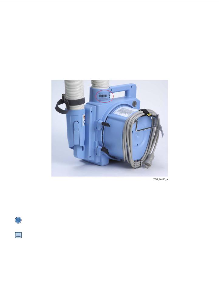
Prior to servicing the warming unit, note the unit’s serial number, software version, and any error codes.
The serial number is located on the back of the warming unit (Figure 1-1).
Figure 1-1. Serial Number Label on Back of Warming Unit
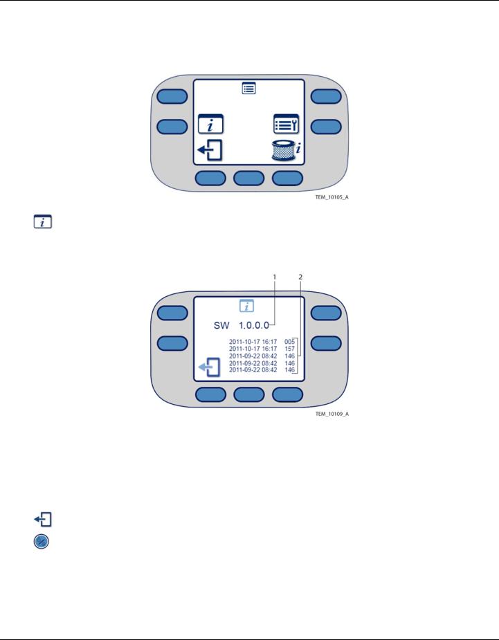
The software version number and error codes can be obtained from the warming unit’s System Information screen as described below.
To access the System Information screen:
1.Plug the warming unit’s power cord into the outlet, and press the On/Standby key.
2. Press the Menu key. The Menu screen appears (Figure 1-2).
Service Manual |
1-9 |
Introduction
Figure 1-2. Menu Screen
3.Press the System Information key. The System Information screen shows the software version and the most recent error messages, if any (Figure 1-3).
Figure 1-3. System Information Screen
1 Software Version |
2 Error Messages (Up to Six) |
Note:
Time stamps associated with error messages do not necessarily reflect local time. The warming unit is set to UTC (Coordinated Universal Time) at manufacture.
4.To return to the Main screen, press the Exit key twice.
5.Press the On/Standby key to power off the unit.
1-10 |
Service Manual |

Component Disposal - WEEE Directive
1.6 Component Disposal - WEEE Directive
The warming unit contains components that must be disposed of in accordance with WEEE Directive. Do not dispose of the warming unit as a whole or the following individual components as unsorted municipal waste:
•Power cord – page 8-5
•Display (LCD) – page 10-8
•User Interface (UI) PCBA – page 10-12
•Clock battery – page 10-29
•Power PCBA – page 10-31
•Power supply – page 10-43
Service Manual |
1-11 |
Introduction
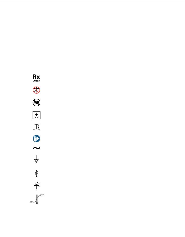
1.7 Labeling Symbols
Table 1-3 defines the symbols that appear on the warming unit or its shipping label.
Table 1-3. Symbols on the Warming Unit and Shipping Label
Symbol |
Description |
Appears On... |
|
|
|
|
|
|
|
Warming |
Shipping |
|
|
Unit |
Label |
|
|
|
|
|
By prescription only |
X |
X |
|
|
|
|
|
No Free Hosing: Hose nozzle must be connected to a |
X |
|
|
WarmTouch™ blanket or thermal injury may occur. |
|
|
|
|
|
|
|
Do not use during magnetic resonance imaging (MRI). |
X |
X |
|
|
|
|
|
Degree of protection from electric shock: |
X |
|
|
Protection Class I, Type BF applied part |
|
|
|
|
|
|
|
Recommendation to consult accompanying documents |
X |
X |
|
|
|
|
|
Requirement to consult accompanying documents |
X |
X |
|
|
|
|
|
Nature of power supply: Alternating Current (AC) |
X |
|
|
|
|
|
|
Potential equalization conductor terminal |
X |
|
|
Used to access the warming unit’s electrical ground for |
|
|
|
electrical safety testing |
|
|
|
|
|
|
|
Universal Serial Bus (USB) port |
X |
|
|
(For service use by qualified personnel only) |
|
|
|
|
|
|
|
Keep dry |
X |
X |
|
|
|
|
|
Temperature limitations (shipping/storage): -40°C to |
|
X |
|
+70°C |
|
|
|
|
|
|
1-12 |
Service Manual |
Labeling Symbols
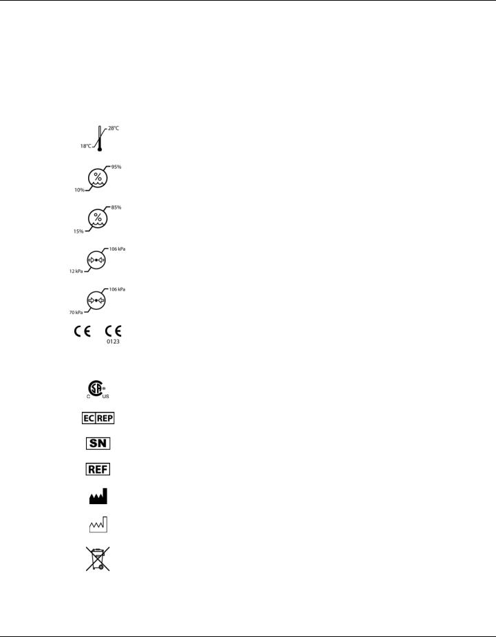
Table 1-3. Symbols on the Warming Unit and Shipping Label (Continued)
Symbol |
Description |
Appears On... |
|
|
|
|
|
|
|
Warming |
Shipping |
|
|
Unit |
Label |
|
|
|
|
|
Temperature limitations (operating): +18°C to +28°C |
X |
|
|
|
|
|
|
Relative humidity limitations (shipping/storage): 10% to |
|
X |
|
95% (non-condensing) |
|
|
|
|
|
|
|
Relative humidity limitations (operating): 15% to 85% |
X |
|
|
(non-condensing) |
|
|
|
|
|
|
|
Atmospheric pressure limitations (shipping/storage): |
|
X |
|
12 kPa to 106 kPa |
|
|
|
|
|
|
|
Atmospheric pressure limitations (operating): 70 kPa to |
X |
|
|
106 kPa |
|
|
|
|
|
|
|
CE – Conformité Européene authorization mark |
X |
X |
|
0123 – TÜV SÜD Product Service GmbH (notified body) |
|
|
|
Signifies compliance with Medical Device Directive |
|
|
|
93/42/EEC |
|
|
|
|
|
|
|
CSA – Canadian Standards Association certification |
X |
|
|
mark |
|
|
|
|
|
|
|
European Community (EC) authorized representative |
X |
X |
|
|
|
|
|
Serial number |
X |
X |
|
|
|
|
|
Catalog number |
X |
X |
|
|
|
|
|
Manufacturer |
X |
X |
|
|
|
|
|
Date of manufacture |
X |
X |
|
|
|
|
|
Proper waste disposal for electrical and electronic equip- |
X |
|
|
ment (WEEE) |
|
|
|
|
|
|
Service Manual |
1-13 |

Introduction
1.8 Obtaining Technical Assistance
For technical assistance or to order parts and additional manuals, contact Covidien Technical Services or a local Covidien representative.
When contacting Covidien for troubleshooting or service issues, please provide the information described in Serial Number, Software Version, and Error Codes on page 1-9.
Covidien Technical Services
Covidien Argentina |
Covidien Asia |
Covidien Australia |
Aguero 351 |
Singapore Regional Service |
52A Huntingwood Drive |
Capital Federal - 1171 ABC |
Centre |
Huntingwood, NSW 2148 |
Argentina |
15 Pioneer Hub, #06-04 |
Australia |
Tel: (5411) 4863-5300 |
Singapore 627753 |
Tel: (+61) 1800 - 350702 |
Fax: (5411) 4863-4142 |
Tel (65) 6578 5288 |
Fax: (+61) 2967 - 18118 |
|
Fax (65) 6515 5260 |
|
Covidien Austria GmbH |
Covidien Belgie S.A.-N.V. |
Covidien Brazil |
Campus21 |
Generaal De Wittelaan 9/5 |
Av. Das Nações Undias 12995 |
Europaring F09402 |
Mechelen |
Andar 23 - Brooklin |
Brunn am Gebrige |
2800 |
São Paulo, SP |
A-2345 Österreich |
België |
Brasil 04578-000 |
Tel: (+43) 2236 - 3788 39 |
Tel +32 152 981 37 |
Tel: (5511) 2187-6200 |
Fax: (+43) 2236 - 3788 3940 |
Fax +32 152 167 83 |
Fax: (5511) 2187-6380 |
Covidien Canada |
Covidien Chile |
Covidien China |
19600 Clark Graham |
Camino lo Boza (Ex 8395) |
2F, Tyco Plaza |
Baie d'Urfe, QC, H9X 3R8 |
Pudehuel |
99 Tian Zhou Rd |
Canada |
Santiago |
Shang Hai 200233 |
Tel:1-514-695-1220, Ext.4004 |
Chile |
P.R. China |
Fax: 1-514-695-4965 |
Tel: (562) 739 - 3000 |
Tel: (+86) 4008 1886 86 |
|
Fax: (562) 783 - 3149 |
Fax: (+86) 2154 4511 18 |
Covidien Colombia |
Covidien Costa Rica |
Covidien ECE |
Edificio Prados de la Morea |
Global Park, Parkway 50 |
Prosecká 851/64 |
Carretera Central Del Norte |
La Auroa de Heredia |
190 00 Praha 9 |
(Cra 7a) Kilometro 18, |
Costa Rica |
Česká republika |
Chia-Cundinamarca |
Tel: (506) 2239 - 5386 |
Tel: +420 239 000 711 |
Bogota, Colombia |
Fax: (506) 2239 - 5319 |
Fax: +420 239 000 437 |
Tel: (571) 619-5469 |
|
|
Fax: (571) 619-5425 |
|
|
1-14 |
Service Manual |

Obtaining Technical Assistance
Covidien Technical Services (Continued)
Covidien Danmark A/S |
Covidien Deutschland |
Covidien ECE |
Langebrogade 6E, 4. sal |
GmbH |
Galvaniho 7/a |
1411 København K |
Technisches Service Center |
821 04 Bratislava |
Danmark |
Raffineriestr. 18 |
Slovakia |
Tel +45 702 753 50 |
93333 Neustadt / Donau |
Tel.: +421 248 214 573 |
Fax:+45 702 756 50 |
Germany |
Fax: +421 248 214 501 |
|
Tel + 49 944 595 93 80 |
|
|
Fax + 49 944 595 93 65 |
|
|
|
|
Covidien Finland Oy |
Covidien France SA |
Covidien Hong Kong |
Läkkisepäntie 23 |
Parc d'affaires Technopolis |
Unit 12 - 16, 18/F |
00620 Helsinki |
Bat. Sigma, 3 Avenue du |
BEA Tower |
Finland |
Canada |
Millennium City 5 |
Te. +35 896 226 84 10 |
LP 851 Les Ulis |
4187 Kwun Tong Road |
Fax +35 896 226 84 11 |
91975 Courtaboeuf Cedex |
Kwum Tong, |
|
France |
Kowloon, Hong Kong |
|
Tel +33 169 821 416 |
Tel + 852 3157 7299 |
|
Fax +33 169 821 532 |
Fax + 852 2838 0749 |
|
|
|
Covidien India |
Covidien Hungary |
Covidien Ireland |
10th Floor Building No 9B |
1095 Budapest |
Block G, Ground Floor, |
DLF Cyber City Phase III |
Mariassy u. 7 |
Cherrywood Technology Park, |
Gurgaon |
Magyarorszag |
Loughlinstown |
Haryana - 122002 |
Hungary |
County Dublin, Ireland |
India |
Tel + 36 1880 7975 |
Tel +353 1 4381613 |
Tel + 91 1244 709800 |
Fax + 36 1777 4932 |
Fax 353 1 439 3039 |
Fax + 91 1244 206850 |
|
|
|
|
|
Covidien Israel |
Covidien Italia S.p.A. |
Covidien Japan Inc. |
5 Shacham St. |
Via Rivoltana 2/D |
Technical Support Center |
North Industrial Park |
20090 Segrate |
83-1, Takashimadaira 1- |
Caesarea |
Italy |
Chome |
38900 Israel |
Tel +39 027 030 81 31 |
Itabashi-ku, Tokyo 175-0082 |
Tel +97 246 277 388 |
Fax +39 027 031 72 84 |
Japan |
Fax+97 266 277 688 |
|
Tel: +81 (0) 3 6859 0120 |
|
|
Fax: +81 (0) 3 6859 0142 |
|
|
|
Covidien Korea |
Covidien Mexico |
Covidien Nederland BV |
5F, Hibrand Living Gwan, |
Insurgentes Sur # 863, Piso 16 |
Hogeweg 105 |
#215, |
Col. Nápoles |
5301 LL Zaltbommel |
Yangjae-Dong, |
Del. Benito Juarez |
Nederland |
Seocho-Gu |
Mexico, D.F. 03810 Mexico |
Tel +31 41 857 66 00 |
Seoul, Korea |
Tel: (5255) 5804-1524 |
|
Tel: +822 570 5459 |
Fax: (5255) 5536-1326 |
|
Fax: +822 570 5499 |
|
|
|
|
|
Service Manual |
1-15 |

Introduction
Covidien Technical Services (Continued)
Covidien Norge AS |
Covidien Panama |
Covidien Polska |
Postboks 343 |
Parque Industrial Costa del Esta |
Al. Jerozolimskie 162 |
1372 Asker. |
Calle Primera, Edifio # 109 |
Warszawa. 02-342 |
Norway |
Panama City, Panama |
Polska |
Tel +47 668 522 22 |
Tel: (507) 264-7337 |
Tel +48 223 122 130 |
Fax +47 668 522 23 |
Fax: (507) 236-7408 |
Fax +48 223 122 020 |
Covidien Portugal Lda. |
Covidien Puerto Rico |
Covidien Russia |
Estrada do Outeiro de Polima, |
Palmas Industrial Park |
53 bld. 5 Dubininskaya Street |
Lote 10-1° Abóboda |
Road 869 Km 2.0 Bdlg. #1 |
Moscow |
2785-521 S.Domingos de Rana |
Cataño, PR 00962 |
RUSSIA. 119054 |
Portugal |
Tel. 787-993-7250 |
Tel +70 495 933 64 69 |
Tel +35 121 448 10 36 /30 |
Ext. 7222 & 7221 |
Fax +70 495 933 64 68 |
Fax +35 121 445 1082 |
Fax 787-993-7234 |
|
Covidien Saglik A.S. |
Covidien South Africa |
Covidien Spain S.L. |
Maslak Mahallesi Bilim Sokak |
Corporate Park North |
Business Park World Trade |
No: 5, Sun Plaza Kat: 2-3 |
379 Roan Crescent |
Center Almeda Park Edificio |
Sisli, Istanbul 34398 |
Randjespark |
7 - 3ª planta Plaça de la Pau s/n |
Turkey |
Midrand, South Africa |
Cornellà de Llobregat |
Tel +90 212 366 20 00 |
Tel +27 115 429 500 |
|
Fax +90 212 276 35 25 |
Fax +27 115 429 624 |
|
Covidien Sverige AB |
Covidien Switzerland |
Covidien Thailand |
Box 54 |
Roosstrasse 53 |
99 Soi Rubia, |
171 74 Solna |
8832 Wollerau |
Sukhumvit 42 Road |
Sweden |
Schweiz |
13 - 14 Fl., Berli Jucker Building |
Tel +46 858 56 05 00 |
Tel +41 44786 5050 |
Prakanong, Klongtoey |
Fax + 46 858 56 05 29 |
Fax +41 44786 5010 |
Bangkok 10110, Thailand |
|
|
Tel +662 2073 - 100 |
|
|
Fax +662 657 - 6325 |
Covidien UK |
Covidien US |
Unit 2, Talisman Business Park |
15 Hampshire Street |
London Road, Bicester |
Mansfield, MA 02048 USA |
OX26 6HR, United Kingdom |
Tel 1.800.635.5267 |
Tel +44(0)1869 328092 |
Tel 1.925.463.4635 (toll) |
Fax +44(0)1869 327585 |
|
1-16 |
Service Manual |
Loading...