


 Loading...
Portable Bedside Capnograph/Pulse Oximeter
Service Manual
CI05225E
Notice: Purchase of this instrument confers no express or implied license under any Oridion Medical patent or Nellcor Puritan Bennett patent to use the instrument with any accessory that is not manufactured or licensed by Oridion Medical 1987 Ltd.
Capnography is covered by one or more of the following United States patents: 6,491,643; 6,656,127; 6,168,958; 5,300,859 and 4,755,675 and their foreign equivalents.
1980816
Microstream® and FilterLine® are registered trademarks and Smart CapnoLine™, CapnoLine™, Smart BiteBloc™ and NIV Line™ are trademarks of Oridion Medical 1987 Ltd.
Nellcor Puritan Bennett Incorporated is an affiliate of Tyco Healthcare.
The following are trademarks of Nellcor Puritan Bennett Incorporated: Oxiband®; Durasensor®; OxiCliq®; Dura-Y®; and OXIMAX®.
Pulse Oximetry is covered by one or more of the following US patents and foreign equivalents: 4,802,486; 4,869,254; 4,928,692; 4,934,372; 5,078,136; 5,485,847; 5,743,263; 5,865,736; 6,035,223; 6,298,252; 6,463,310; 6,591,123; 6,675,031; 6,708,049; 6,801,797; Re 35,122.

TABLE OF CONTENTS
List of Figures
List of Tables
Section 1: Introduction........................................................................ |
1-1 |
||
1.1 |
Manual Overview ............................................................... |
1-1 |
|
1.2 |
Warnings, Cautions, and Notes ......................................... |
1-1 |
|
|
1.2.1 |
Warning.............................................................. |
1-1 |
|
1.2.2 |
Caution............................................................... |
1-1 |
|
1.2.3 |
Note.................................................................... |
1-1 |
1.3 |
Product Description ........................................................... |
1-2 |
|
Section 2: Required Equipment.......................................................... |
2-1 |
||
2.1 |
Required Equipment .......................................................... |
2-1 |
|
Section 3: Cleaning |
........................................................................... |
3-1 |
|
3.1 |
Cleaning |
........................................................................... |
3-1 |
|
3.1.1 |
Procedure........................................................... |
3-1 |
Section 4: Service Mode...................................................................... |
4-1 |
||
4.1 |
Introduction ........................................................................ |
4-1 |
|
4.2 |
Service Level 1 .................................................................. |
4-1 |
|
|
4.2.1 |
Information Screen............................................. |
4-1 |
|
4.2.2 |
Event Messages Screen .................................... |
4-1 |
|
4.2.3 |
Interface Test Screen......................................... |
4-2 |
|
4.2.4 |
Accessing Service Mode and Service Level 1 ... |
4-3 |
4.3 |
Service Level 2 .................................................................. |
4-5 |
|
|
4.3.1 |
Default Alarm Limits........................................... |
4-7 |
|
4.3.2 |
Default Settings.................................................. |
4-9 |
|
4.3.3 |
Flow Calibration ............................................... |
4-10 |
Section 5: Troubleshooting................................................................. |
5-1 |
||
5.1 |
Introduction ........................................................................ |
5-1 |
|
5.2 |
Who Should Perform Repairs ............................................ |
5-1 |
|
5.3 |
Repair Level Supported ..................................................... |
5-1 |
|
5.4 |
How to Use This Section ................................................... |
5-1 |
|
5.5 |
Obtaining Replacement Parts............................................ |
5-1 |
|
5.6 |
Troubleshooting Guide ...................................................... |
5-2 |
|
Section 6: Flow Calibration Check ..................................................... |
6-1 |
||
6.1 |
Introduction ........................................................................ |
6-1 |
|
6.2 |
Flow Rate Check ............................................................... |
6-1 |
|
6.3 |
Flow Calibration Process ................................................... |
6-2 |
|
Section 7: Disassembly Guide............................................................ |
7-1 |
||
7.1 |
Introduction ........................................................................ |
7-1 |
|
7.2. |
Opening the Monitor Case................................................. |
7-2 |
|
7.3 |
Replacing the CO2 Board .................................................. |
7-4 |
|
7.4 |
Replacing the SpO2 Board................................................. |
7-5 |
|
7.5 |
Replacing the Pump .......................................................... |
7-6 |
|
7.6 |
Replacing the Flow System ............................................... |
7-7 |
|
|
7.6.1 |
Replacing the lines to the pump......................... |
7-8 |
|
7.6.2 |
Replacing the lines to the solenoid .................... |
7-9 |
7.7 |
Replacing LCD and LED Display..................................... |
7-11 |
|
|
7.7.1 |
Replacing the LCD........................................... |
7-11 |
|
7.7.2 |
Replacing the LED Display .............................. |
7-11 |
iii

Table of Contents
7.8 |
Replacing Housing Components ..................................... |
7-12 |
|
|
7.8.1 |
ON-OFF Button and Gas Outlet....................... |
7-12 |
|
7.8.2 |
Keypads ........................................................... |
7-12 |
|
7.8.3 |
Front Cover ...................................................... |
7-13 |
|
7.8.4 |
SpO2 Connector Latch, Rear Cover and |
|
7.9 |
|
SpO2 Insulation Plate....................................... |
7-13 |
Updating Software Version .............................................. |
7-14 |
||
Section 8: Electrical Safety Tests....................................................... |
8-1 |
||
8.1 |
Electrical Safety Tests ....................................................... |
8-1 |
|
Section 9: Periodic Maintenance ........................................................ |
9-1 |
||
9.1 |
Periodic Maintenance ........................................................ |
9-1 |
|
Section 10: Performance Verification............................................... |
10-1 |
||
10.1 |
Flow System Leak Check ................................................ |
10-1 |
|
|
10.1.1 |
Flow System Leak Check Procedure ............... |
10-1 |
10.2 |
Performance Verification Procedure................................ |
10-2 |
|
Section 11: Packing For Shipment ................................................... |
11-1 |
||
11.1 |
General Instructions......................................................... |
11-1 |
|
11.2 |
Packing Monitor in Original Carton .................................. |
11-1 |
|
11.3 |
Packing in a Different Carton........................................... |
11-1 |
|
Section 12: Specifications................................................................. |
12-1 |
||
12.1 |
Physical |
......................................................................... |
12-1 |
|
12.1.1 |
Size .................................................................. |
12-1 |
|
12.1.2 |
Weight.............................................................. |
12-1 |
|
12.1.3 |
Noise Emission ................................................ |
12-1 |
12.2 |
Environmental.................................................................. |
12-1 |
|
|
12.2.1 |
Temperature..................................................... |
12-1 |
|
12.2.2 |
Relative Humidity ............................................. |
12-1 |
|
12.2.3 |
Pressure and Altitude....................................... |
12-1 |
12.3 |
Safety Standards ............................................................. |
12-1 |
|
12.4 |
Performance .................................................................... |
12-2 |
|
|
12.4.1 |
Capnograph ..................................................... |
12-2 |
|
12.4.2 |
Pulse Oximeter................................................. |
12-3 |
12.5 |
Power Specifications ....................................................... |
12-4 |
|
|
12.5.1 |
External Power Source .................................... |
12-4 |
|
12.5.2 |
Internal Power Source...................................... |
12-4 |
12.6 |
Components and User interface ...................................... |
12-4 |
|
|
12.6.1 |
Displays............................................................ |
12-4 |
|
12.6.2 |
Controls and Indicators .................................... |
12-4 |
|
12.6.3 |
Connections ..................................................... |
12-4 |
Section 13: Spare Parts ..................................................................... |
13-1 |
||
13.1 |
Spare Parts List ............................................................... |
13-1 |
|
Glossary of Terms |
|
|
|
iv

Table of Contents
LIST OF FIGURES |
|
|
1-1 |
Handheld Capnograph/Pulse Oximeter ............................. |
1-2 |
1-2 |
LCD Graphic Display and 7 Segment Digital Displays ...... |
1-2 |
7-1 |
Removing the Battery Pack ............................................... |
7-2 |
7-2 |
Removing Mounting Screws .............................................. |
7-3 |
7-3 |
Separating Rear and Front Covers.................................... |
7-3 |
7-4 |
Replacing CO2 Board and Housing Components.............. |
7-4 |
7-5 |
Replacing SpO2 Board....................................................... |
7-5 |
7-6 |
Replacing the Pump .......................................................... |
7-6 |
7-7 |
Flow System ...................................................................... |
7-7 |
7-8 |
Main Line ........................................................................... |
7-8 |
7-9 |
Exhaust Line ...................................................................... |
7-8 |
7-10 |
Lines to Solenoid (Zero line, Input line 1, Input line 2........ |
7-9 |
7-11 |
Zero line........................................................................... |
7-10 |
7-12 |
Replacing LCD and LED Display..................................... |
7-11 |
7-13 |
Replacing SpO2 Connector Latch.................................... |
7-13 |
7-14 |
Replacing EPROM........................................................... |
7-14 |
10-1 |
Leak Test Jig Connection ................................................ |
10-1 |
10-2 |
Initialization Screen.......................................................... |
10-2 |
10-3 |
Self-Test Screen .............................................................. |
10-2 |
10-4 |
Measuring Mode .............................................................. |
10-2 |
10-5 |
Quick Guide ..................................................................... |
10-3 |
10-6 |
Connecting the monitor to Printer/PC with |
|
|
Communication Adapter Kit ............................................. |
10-9 |
11-1 |
Packing the Monitor in Original Packing .......................... |
11-2 |
LIST OF TABLES |
|
|
4-1 |
Accessing Service Mode and Changing Parameter |
|
|
Settings................................................................... |
4-3 |
4-2 |
Accessing Service Level 2................................................. |
4-5 |
4-3 |
Changing Default Alarm Limits .......................................... |
4-7 |
4-4 |
Changing Default Settings ................................................. |
4-9 |
4-5 |
Accessing Flow Calibration.............................................. |
4-10 |
5-1 |
Troubleshooting Guide ...................................................... |
5-2 |
5-2 |
Advisory Messages Guide ................................................. |
5-4 |
5-3 |
Event Messages ................................................................ |
5-5 |
6-1 |
Flow Calibration ................................................................. |
6-2 |
10-1 |
CO2 Calibration Check..................................................... |
10-4 |
10-2 |
Calibration Process.......................................................... |
10-6 |
10-3 |
Calibration Process -Troubleshooting.............................. |
10-7 |
10-4 |
Plethysmograph Waveform ............................................. |
10-8 |
10-5 |
Accessing Monitor’s Print Functions.............................. |
10-10 |
13-1 |
Spare Parts List ............................................................... |
13-1 |
v

Table of Contents

SECTION 1: INTRODUCTION
1.1Manual Overview
1.2Warnings, Cautions, and Notes
1.3Product Description
1.1MANUAL OVERVIEW
This manual contains information for servicing the handheld capnograph/ pulse oximeter (the monitor). Only authorized service personnel should service this product. The Handheld Capnograph/Pulse Oximeter Operator’s Manual (the operator’s manual) is an integral part of the service procedures. Before servicing the monitor, read the operator’s manual carefully for a thorough understanding of how to operate the unit.
Only use the tools and test equipment as specified in this manual. Only use original spare parts available from your local distributor.
Warning: Incorrect procedures may harm the patient, or damage the monitor.
1.2WARNINGS, CAUTIONS, AND NOTES
1.2.1Warning
A warning precedes an action that may result in injury or death to the patient or user. Warnings are boxed and highlighted in boldface type.
1.2.2Caution
A caution precedes an action that may result in damage to, or malfunction of, the monitor. Cautions are highlighted in boldface type.
1.2.3Note
A note gives information that requires special attention.
1-1

Section 1: Introduction
1.3PRODUCT DESCRIPTION
The handheld capnograph/pulse oximeter is used to continuously monitor end-tidal carbon dioxide (EtCO2), respiratory rate, oxygen saturation (SpO2), and pulse rate. The monitor is for attended monitoring only and must be used in the continuous presence of a qualified healthcare provider. The monitor can be used on adult, pediatric, and infant/neonatal patients. It is intended for use where continuous, noninvasive monitoring of these parameters is desired, including hospital and mobile use (when protected from excessive moisture such as direct rainfall). The monitor operates on AC power or a rechargeable Nickel Metal Hydride battery pack.
Figure 1-1: Handheld Capnograph/Pulse Oximeter
The monitor is operated using a four-key keypad. Measurements are displayed on the front panel on the 7-segment LED digital displays (LED) and on the LCD graphic display (LCD) as shown in Figure 1-2. Refer to the operator’s manual for complete operating instructions.
Figure 1-2: LCD Graphic Display and 7-Segment Digital Displays
1-2

SECTION 2: REQUIRED EQUIPMENT
2.1Required Equipment
2.1REQUIRED EQUIPMENT
You will need the following equipment to disassemble, replace parts, check, adjust, or calibrate the monitor.
For disassembly and replacement:
•Phillips-head screwdriver (medium)
•Flat-head screwdriver (small)
•IC Extractor for PLCC socket
•Threadlocker glue e.g. Loctite® 222 super screw lock For checks, adjustments and calibration:
•Calibration Gas (5% CO2 in air)
•FilterLine or FilterLine H and a connecting means
•DS-100A - OXIMAX Durasensor®, Nellcor
•Leak Test Jig
•Vacuum manometer with a range of 0-500 mBar
e.g. MPL-3200-DM, Digital Manometer MicroPneumatic Logic, Inc.
•Communication Adapter Kit (only necessary to verify print functions)
•Seiko DPU-414 printer (only necessary to verify print functions)
•External power supply
•Handheld Capnograph/Pulse Oximeter Operator’s Manual
•Flow Meter (range 0-50 ml/min) e.g. Top Track Mass Flow Meter, model: 822-13-OV1-PV1-V1, Sierra Instruments, Inc.
Warning: Observe ESD (electrostatic discharge) precautions when handling, adjusting or performing any procedure with the monitor’s internal components.
2-1

SECTION 3: CLEANING
3.1Cleaning
3.1CLEANING
Always clean the outer surface of the monitor before servicing.
Warning: Always wear latex or surgical gloves when cleaning or servicing the monitor after hospital use.
Warning: Do not allow liquids to drip inside the housing.
Warning: Do not clean internal components.
Warning: Do not use preparations based on: phenols, halogen producing compounds, strong organic acids, or oxygen producing compounds.
3.1.1Procedure
1.Unplug the unit from AC power.
2.With a damp cloth, gently wipe the outer case of the monitor with a disinfectant based on aldehyde, alcohol or quaternary ammonium producing compounds.
3-1
SECTION 4: SERVICE MODE
4.1Introduction
4.2Service Level 1
4.3Service Level 2
4.1INTRODUCTION
The monitor supports a service mode built into the instrument’s firmware. To access the service mode, refer to Table 4-1: "Accessing Service Mode and Changing Parameter Settings".
The architecture of the monitor’s service mode divides the service mode into two levels as described in the sections below.
•Service Level 1
•Service Level 2
4.2SERVICE LEVEL 1
The Service Level 1 provides information and tools on three service screens to test and calibrate specific functions without disassembling the monitor.
•Information Screen
•Event Messages Screen
•Interface Test Screen
From these display screens the service technician can check the operating hours counter and event messages, test the Human Interface functions (HMI), set the light detection threshold, adjust the LCD contrast middle point and do a calibration check and a calibration process, if necessary. Refer to Table 4-1: "Accessing Service Mode and Changing Parameter Settings".
4.2.1Information Screen
The information screen displays the monitor’s main board serial number, the number of operating hours, and the SpO2 and CO2 boards’ software versions.
4.2.2Event Messages Screen
The monitor automatically performs a series of built-in tests (BITs) at start-up and during operation to check sub-systems and modules for errors. The event messages screen lists the last five event messages, the time each occurred relative to the unit’s operating hours, and a recommended service action. There are three event messages and each has a specific response as follows:
Event Message: |
Action: |
CO2 board |
Replace CO2 board |
SpO2 board |
Replace SpO2 board |
Flow |
Replace CO2 board |
4-1

Section 4: Service Mode
Note: To exit the service mode and save event messages, turn off the monitor. Event messages will be erased when exiting the service mode by a long press of  .
.
4.2.3Interface Test Screen
The interface test screen shows four parameters (listed below) that provide tools for the user to test, adjust, and calibrate the unit’s interfacing systems.
•HMI Test
•Light Detector
•Contrast Cal. (Calibration)
•CO2 Calib. (Calibration)
4.2.3.1 HMI Test
When the HMI Test is turned on, the monitor performs a self-test of the following sub-systems:
•Buzzer (sounds for one second)
•LCD graphic display (screen shows a checkerboard pattern)
•7-segment digital display (8s scroll left to right)
•Alarm bar (lights red, yellow, off)
•Backlight (turns on and off)
•Alarm silence indicator (light turns on and off)
When the HMI test is completed the status field returns automatically to
OFF.
4.2.3.2 Light Detector
The Light Detector parameter allows the service technician to set the threshold value of the phototransistor. The default value is 1 and the range is from 1 to 5 with 1 as the most sensitive (backlight on at all times) and 5 as the least sensitive (backlight off). The threshold value should be set according to the lighting conditions of the working environment. A higher threshold value saves on battery power consumption.
4.2.3.3 Contrast Cal. (calibration)
The Contrast Cal. gives the service technician the option to change the middle point default value of the contrast intensity of the LCD. Refer to Table 4-1: "Accessing Service Mode and Changing Parameter Settings".
4.2.3.4 CO2 Calib. (calibration)
The CO2 Calib. allows the service technician to perform a calibration check and calibration process to ensure the accuracy of the monitor. Section 10: Performance Verification describes the calibration check procedure.
4-2

Section 4: Service Mode
4.2.4Accessing Service Mode and Service Level 1.
Table 4-1: "Accessing Service Mode and Changing Parameter Settings" describes the process to access the service mode, change parameter settings and how to change Contrast Cal. settings.
Table 4-1: Accessing Service Mode and Changing Parameter Settings
Objective |
Action |
Response |
|
|
|
|
|
To access Service Mode |
During self-test, |
Self-test occurs and the |
|
|
long press |
Information Screen |
|
|
simultaneously |
appears: |
|
|
and |
|
|
|
|
|
|
|
|
|
|
To access Event |
long press |
|||||||||
Messages screen |
|
|
|
|
|
|
|
|
|
|
|
|
|
|
|
|
|
|
|
|
|
To access Interface |
long press |
|
|
|
|
|
|
|
|
|
|
|
|
|
|
|
|
|
|
||
Test screen |
|
|
|
|
|
|
|
|
|
|
|
|
|
|
|
|
|
|
|
|
|
|
|
|
|
|
|
|
|
|
|
|
|
|
|
|
|
|
|
|
|
|
|
|
|
|
|
|
|
|
|
|
|
|
|
|
|
|
|
|
|
|
|
|
|
|
|
|
|
|
|
|
|
|
|
|
To change the |
short press |
|||||||||
parameter setting or |
|
|
|
|
|
|
|
|
|
|
|
|
|
|
|
|
|
|
|
|
|
value |
|
|
|
|
|
|
|
|
|
|
|
|
|
|
|
|
|
|
|
|
|
|
|
|
|
|
|
|
|
|
|
|
|
|
|
|
|
|
|
|
|
|
|
|
|
|
|
|
|
|
|
|
|
|
|
|
|
|
|
|
|
|
|
|
|
To move to the next |
short press |
|||||||||
parameter |
|
|
|
|
|
|
|
|
|
|
|
|
|
|
|
|
|
|
|
|
|
|
|
|
|
|
|
|
|
|
|
|
|
|
|
|
|
|
|
|
|
|
|
|
|
|
|
|
|
|
|
|
|
|
|
|
|
|
|
|
|
|
|
|
|
|
|
|
|
|
|
|
|
|
|
|
4-3
Section 4: Service Mode
Table 4-1: Accessing Service Mode and
Changing Parameter Settings (Continued)
Objective |
Action |
Response |
|
|
|
To change Contrast |
short press |
|
Cal. setting to set |
|
|
To start Contrast Cal. |
short press |
“Contrast Cal.” flashes. |
|
|
|
To adjust Contrast |
press |
|
Cal. middle point |
|
Screen lightens or |
|
|
|
|
until desired |
darkens |
|
|
|
|
setting is reached. |
|
|
(Pressing on the left |
|
|
lightens the screen, |
|
|
and pressing on the |
|
|
right darkens the |
|
|
screen.) |
|
|
|
|
To accept new setting |
short press |
|
To reset and return to |
long press |
||||||
measuring mode |
|
|
|
|
|
|
|
(automatically erasing |
|
|
|
|
|
|
|
the event messages |
|
|
|
|
|
|
|
memory) |
|
|
|
|
|
|
|
|
|
|
|
|
|
|
|
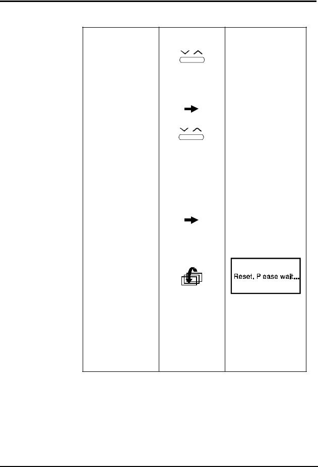
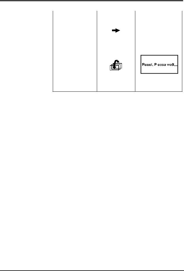
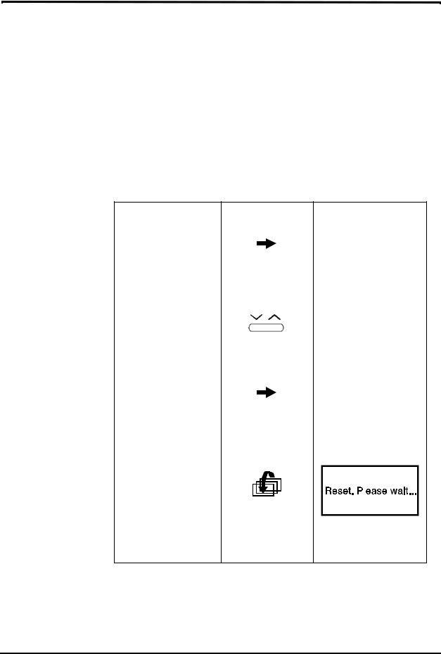
Note: Reset time is approximately one minute.
To exit service mode |
Turn off the |
from any service |
monitor. |
screen without erasing |
|
the event messages |
|
memory |
|
4-4
Section 4: Service Mode
4.3SERVICE LEVEL 2
The Service Level 2 gives the service technician tools on three service screens:
•Default Alarm Limits
•Default Settings
•Flow Calibration
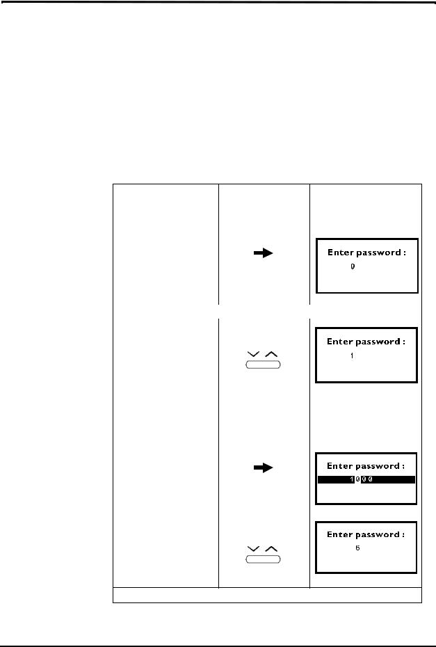
To access this service level, the service technician must enter a valid password (1627), refer to Table 4-2: "Accessing Service Level 2".
Note: The password should not be disclosed to avoid unauthorized setting of parameters.
Table 4-2: Accessing Service Level 2
Objective |
Action |
Response |
|
|
|
To access |
After entering the |
Password Screen |
Service Level 2 |
service mode |
appears |
|
long press (x3) |
|
|
|
|
|
|
|
|
|
|
|
|
|
|
|
Enter Password: 1627 |
|
|
|
|
|
|
|
|
|
|
|
|
|
Enter the 1st digit |
short press (right) |
|||||
|
(x1) |
|||||
|
|
|
|
|
|
|
|
|
|
|
|
|
|
|
Pressing on the |
|||||
|
right arrow scrolls |
|||||
|
the numbers up, |
|||||
|
the left arrow |
|||||
|
scrolls the numbers |
|||||
|
down. |
|||||
|
|
|
|
|
|
|
Move to the next digit |
short press |
|||||
|
|
|
|
|
|
|
|
|
|
|
|
|
|
Enter the 2nd digit |
short press (right) |
||
|
x6 |
||
|
|
|
|
|
|
|
|
Repeat the same procedure as above for the next two digits (2, 7).
4-5
Section 4: Service Mode
Table 4-2: Accessing Service Level 2 (Continued)
Objective |
Action |
Response |
|
|
|
To accept the last digit |
short press |
|
and access the Default |
|
|
Alarm Limits menu |
|
|
|
|
|
In case you entered a |
|
|
wrong digit: |
|
|
To restart password |
long press |
||||
validation process |
|
|
|
|
|
|
|
|
|
|
|
|
|
|
|
|
|
To return to the |
long press |
||||
Interface Test Screen |
|
|
|
|
|
|
|
|
|
|
|
|
|
|
|
|
|
|
|
|
|
|
|
|
|
|
|
|
|
|
|
|
|
|
|
|
|
|
|
|
|
|
|
|
|
|
|
|
|
|
|
|
|
|
|
|
|
|
|
|
|
|
|
|
|
|
|
To exit service mode |
Turn off the |
||||||
and save event |
monitor. |
||||||
messages |
|
|
|
|
|
|
|
4-6

Section 4: Service Mode
4.3.1Default Alarm Limits
The service technician can change the default alarm limits for either patient mode (Adult or Neonatal) as described in Table 4-3: "Changing Default Alarm Limits".
The monitor has the following alarms with adjustable level settings:
•EtCO2 high and low levels (mmHg)
•FiCO2 high level (mmHg)
•SpO2 high and low levels (%)
•Pulse rate high and low levels (bpm)
Warning: Changing default settings will permanently change the user’s start-up value and should be verified with the responsible clinical personnel.
Table 4-3: Changing Default Alarm Limits
Objective |
Action |
Response |
|
|
|
To access the Default |
short press |
|
Alarm Limits menu |
|
|
after entering last |
|
|
password digit |
|
|
|
|
|
To change the patient |
short press |
|
mode |
|
|
|
|
|
|
|
|
|
|
|
|
|
|
To access a new |
short press |
||||
parameter |
|
|
|
|
|
|
|
|
|
|
|
|
|
|
|
|
|
To change the value |
short press |
4-7
Section 4: Service Mode
Table 4-3: Changing Default Alarm Limits (Continued)
Objective |
Action |
Response |
|
|
|
To reset to measuring |
long press |
|
mode (automatically |
|
|
erasing event |
|
|
messages) |
|
|
|
then long press |
|
|
|
|
|
|
|
|
|
|
|
|
|
|
|
|
|
|
|
|
|
|
|
|
|
|
|
|
|
|
|
|
|
|
|
|
To exit service mode |
Turn off the |
|||||
and save event |
monitor. |
|||||
messages |
|
|
|
|
|
|
4-8
Section 4: Service Mode
4.3.2Default Settings
The service technician can change two default settings (refer to Table 4-4: "Changing Default Settings"):
•3 Min Alert
When the 3 Min Alert is ON, the unit will beep every three minutes to remind the user that an alarm (or all alarms) are set to OFF.
•BTPS (body temperature, pressure, saturation)
When BTPS is ON, the CO2 value is corrected for this factor
•Pulse Tone
Pulse Tone default is ON. When changed to OFF, the Pulse Tone default is silent (as indicated on screen).
.
Table 4-4: Changing Default Settings
Objective |
Action |
Response |
|
|
|
To access the Default |
long press |
|
Settings menu (after |
|
|
accessing the Default |
|
|
Alarm Limits menu) |
|
|
|
|
|
To change the setting |
short press |
|
To access BTPS |
short press |
|||||
parameter (and save |
|
|
|
|
|
|
the changed setting for |
|
|
|
|
|
|
3 Min Alert) |
|
|
|
|
|
|
|
|
|
|
|
|
|
To reset and return to |
long press |
|||||
measuring mode |
|
|
|
|
|
|
(automatically erasing |
|
|
|
|
|
|
event messages |
|
|
|
|
|
|
|
|
|
|
|
|
|
|
|
|
|
|
|
|
|
|
|
|
|
|
|
memory) |
|
|
|
|
|
|
|
|
|
|
|
|
|
|
|
|
|
|
|
|
|
|
|
|
|
|
|
To exit service mode |
Turn off the |
|||||
and save event |
monitor. |
|||||
message |
|
|
|
|
|
|
4-9
Loading...