


 Loading...
This ISM device complies with Canadian ICES-001.
Cet appareil ISM est conforme à la norme NMB-001 Canada.
Nellcor Puritan Bennett Inc. is an affiliate of Tyco Healthcare. Nellcor, Oxiband, Durasensor, OxiCliq, OxiBand, Dura-Y, MAX-FAST, SatSeconds, PediCheck, Oxismart and OXIMAX are trademarks of Nellcor Puritan Bennett Inc.
To obtain information about a warranty, if any, contact Nellcor’s Technical Services Department, or your local representative.
Purchase of this instrument confers no express or implied license under any Nellcor Puritan Bennett patent to use the instrument with any sensor that is not manufactured or licensed by Nellcor Puritan Bennett.
Covered by one or more of the following U.S. Patents and foreign equivalents: 4,621,643; 4,653,498; 4,700,708; 4,770,179; Re. 35,122; 4,802,486; 4,869,254; 4,928,692; 4,934,372; 5,078,136; 5,351,685; 5,368,026; 5,485,847; 5,533,507; 5,662,106; 5,853,364, and 6,083,172.

C o n t e n t s
Contents . . . . . . . . . . . . . . . . . . . . . . . . . . . . . . . . . . . . . . . . . . . . . . . . . . . . .i
Figures . . . . . . . . . . . . . . . . . . . . . . . . . . . . . . . . . . . . . . . . . . . . . . . . . . . . . v
Tables . . . . . . . . . . . . . . . . . . . . . . . . . . . . . . . . . . . . . . . . . . . . . . . . . . . . . .vi
Safety Information . . . . . . . . . . . . . . . . . . . . . . . . . . . . . . . . . . . . . . . . . . . . 1
Warnings ................................................................................. |
1 |
Cautions .................................................................................. |
2 |
Notes ....................................................................................... |
3 |
Introduction . . . . . . . . . . . . . . . . . . . . . . . . . . . . . . . . . . . . . . . . . . . . . . . . . 5
Intended Use for the N-550 ..................................................... |
5 |
Description of Controls, Indicators, and Symbols . . . . . . . . . . . . . . . . . . 7
Identification of Front Panel Buttons and Symbols |
..................7 |
Identification of Rear Panel Components ................................ |
8 |
N-550 Symbols ........................................................................ |
8 |
Description of Controls ............................................................ |
9 |
Description of Displays and Indicators .................................. |
11 |
Description of Audible Indicators ........................................... |
13 |
Setting up the N-550 . . . . . . . . . . . . . . . . . . . . . . . . . . . . . . . . . . . . . . . . . . 15
List of Components ............................................................... |
16 |
Connecting the N-550 to AC Power ...................................... |
17 |
Connecting a Sensor to the N-550 ........................................ |
17 |
Battery Operation . . . . . . . . . . . . . . . . . . . . . . . . . . . . . . . . . . . . . . . . . . . . 19
Operating the N-550 on Battery Power ................................. |
19 |
Low Battery Indicator ............................................................. |
20 |
Using the N-550 . . . . . . . . . . . . . . . . . . . . . . . . . . . . . . . . . . . . . . . . . . . . . 21
Turning on the N-550 ............................................................ |
21 |
Discussion .................................................................... |
21 |
Procedure .................................................................... |
21 |
Sensor Attached .......................................................... |
24 |
No Sensor Attached ..................................................... |
26 |
Sensor Message ................................................................... |
26 |
N-550 |
i |

Contents
Setting the Pulse Beep Volume ............................................ |
27 |
Setting the Alarm Volume ..................................................... |
28 |
Setting Alarm Silence Duration ............................................. |
28 |
Discussion ................................................................... |
28 |
Procedure .................................................................... |
29 |
Disabling Audible Alarms ...................................................... |
30 |
Discussion ................................................................... |
30 |
Procedure .................................................................... |
30 |
Verify Patient Settings ........................................................... |
31 |
Alarm Limits Changed Indicator ............................................ |
33 |
Setting Alarm Limits .............................................................. |
34 |
Discussion ................................................................... |
34 |
Procedure .................................................................... |
34 |
Setting SatSeconds Duration ................................................ |
36 |
Discussion ................................................................... |
36 |
Procedure .................................................................... |
36 |
Setting the Data Port Baud Rate ........................................... |
37 |
Discussion ................................................................... |
37 |
Procedure .................................................................... |
37 |
Setting the Data Port Protocol .............................................. |
39 |
Clearing Trend Information ................................................... |
40 |
N-550 Trend . . . . . . . . . . . . . . . . . . . . . . . . . . . . . . . . . . . . . . . . . . . . . . . . .43
Trend Data Operation ........................................................... |
43 |
Trend Data ............................................................................ |
43 |
#1: Trend Print ............................................................. |
44 |
#2: Trend Clear ............................................................ |
44 |
#3: Not Used ................................................................ |
44 |
#4: Baud Rate .............................................................. |
44 |
#5: Data Port Printout .................................................. |
45 |
Option 1 .............................................................. |
45 |
Option 2 .............................................................. |
45 |
Using the Data Port . . . . . . . . . . . . . . . . . . . . . . . . . . . . . . . . . . . . . . . . . . .47
Overview ............................................................................... |
47 |
Connecting to the Data Port .................................................. |
47 |
Data Port Pinouts .................................................................. |
48 |
ii

Contents |
|
Data Port Setup ..................................................................... |
49 |
Discussion .................................................................... |
49 |
Procedure .................................................................... |
50 |
Nurse Call Interface ............................................................... |
53 |
Setting Nurse Call RS-232 Polarity .............................. |
54 |
Setting Nurse Call Relays Normally Open/Closed ....... |
54 |
Printing . . . . . . . . . . . . . . . . . . . . . . . . . . . . . . . . . . . . . . . . . . . . . . . . . . . . 57
Printing N-550 Real-Time Data ............................................. |
57 |
Trend Data Printout ............................................................... |
59 |
Column Headings ........................................................ |
60 |
Data Source ................................................................. |
61 |
Device/Software Revision Level .................................. |
61 |
Alarm Limits ................................................................. |
61 |
N-550 Mode ................................................................. |
62 |
Data Column Headings ................................................ |
62 |
Time ............................................................................. |
62 |
Patient Data ................................................................. |
63 |
Operating Status .......................................................... |
63 |
Sensors and Accessories . . . . . . . . . . . . . . . . . . . . . . . . . . . . . . . . . . . . . 65
Selecting a Sensor ................................................................ |
65 |
Biocompatibility Testing ......................................................... |
68 |
Optional Accessories ............................................................. |
68 |
Foot Switch .................................................................. |
69 |
Visual Alarm Indicator .................................................. |
69 |
Pole Mount Bracket ...................................................... |
70 |
Performance Considerations . . . . . . . . . . . . . . . . . . . . . . . . . . . . . . . . . . 71
Performance Verification ....................................................... |
71 |
N-550 Performance Considerations ...................................... |
71 |
Dysfunctional Hemoglobins ......................................... |
72 |
Anemia ......................................................................... |
72 |
Saturation ..................................................................... |
72 |
Pulse rates ................................................................... |
72 |
Sensor Performance Considerations .................................... |
72 |
N-550 |
iii |

Contents
Operator’s Menu . . . . . . . . . . . . . . . . . . . . . . . . . . . . . . . . . . . . . . . . . . . . .75
Troubleshooting . . . . . . . . . . . . . . . . . . . . . . . . . . . . . . . . . . . . . . . . . . . . .77
Error Codes ........................................................................... |
77 |
Corrective Action ................................................................... |
78 |
EMI (Electro-magnetic Interference) ..................................... |
81 |
Obtaining Technical Assistance ............................................ |
82 |
Maintenance . . . . . . . . . . . . . . . . . . . . . . . . . . . . . . . . . . . . . . . . . . . . . . . . .85
Returning the N-550 .............................................................. |
85 |
Service .................................................................................. |
85 |
Periodic Safety Checks ......................................................... |
86 |
Cleaning ................................................................................ |
86 |
Technical Information . . . . . . . . . . . . . . . . . . . . . . . . . . . . . . . . . . . . . . . . .87
Description of Alarms ............................................................ |
87 |
Factory Defaults .................................................................... |
88 |
SatSeconds Display .............................................................. |
89 |
Describing SatSeconds ......................................................... |
90 |
SatSeconds “Safety Net” ...................................................... |
92 |
Principles of Operation . . . . . . . . . . . . . . . . . . . . . . . . . . . . . . . . . . . . . . . .93
Oximetry Overview ................................................................ |
93 |
Automatic Calibration ............................................................ |
94 |
Functional versus Fractional Saturation ................................ |
95 |
Measured versus Calculated Saturation ............................... |
95 |
Specifications . . . . . . . . . . . . . . . . . . . . . . . . . . . . . . . . . . . . . . . . . . . . . . .97
Performance ......................................................................... |
97 |
Electrical ............................................................................. |
101 |
Environmental Conditions ................................................... |
102 |
Physical Characteristics ...................................................... |
104 |
Compliance ......................................................................... |
105 |
Index . . . . . . . . . . . . . . . . . . . . . . . . . . . . . . . . . . . . . . . . . . . . . . . . . . . . . .109
iv

Contents
F i g u r e s
Figure 1: Front Panel Buttons and Symbols ......................... |
7 |
Figure 2: Rear Panel Symbols .............................................. |
8 |
Figure 3: Data Port Pin Layout ........................................... |
49 |
Figure 4: Real-Time Data Printout ...................................... |
59 |
Figure 5: Trend Data Printout ............................................. |
60 |
Figure 6: Alarm Response with SatSeconds ...................... |
91 |
Figure 7: Oxyhemoglobin Dissociation Curve .................... |
96 |
N-550 |
v |

Contents
Ta b l e s
Table 1: Data Port Pinouts .................................................. |
48 |
|
Table 2: Nellcor Oximetry Sensor Models |
|
|
|
and Patient Weights ......................................... |
66 |
Table 3: |
Operator’s Menu ................................................... |
75 |
Table 4: |
Error Codes ........................................................... |
78 |
Table 5: Factory Default Settings ........................................ |
88 |
|
Table 6: |
Tone Definition ...................................................... |
98 |
vi

S a f e t y I n f o r m a t i o n
Warnings
Warnings are identified by the WARNING symbol shown above.
Warnings alert the user to potential serious outcomes (death, injury, or adverse events) to the patient or user.
WARNING: Explosion hazard. Do not use the N-550 pulse oximeter in the presence of flammable anesthetics or gases.
WARNING: Pulse oximetry readings and pulse signals can be affected by certain ambient environmental conditions, sensor application errors, and certain patient conditions. See the appropriate sections of the manual for specific safety information.
WARNING: Ensure that the speaker is clear of any obstruction.
Failure to do so could result in an inaudible alarm tone.
N-550 |
1 |

Safety Information
Cautions
Cautions are identified by the CAUTION symbol shown above.
Cautions alert the user to exercise care necessary for the safe and effective use of the N-550.
CAUTION: When connecting the N-550 to any instrument, verify proper operation before clinical use. Both the N-550 and the instrument connected to it must be connected to a grounded outlet. Accessory equipment connected to the N-550's data interface must be certified according to IEC Standard 60950 for data-processing equipment or IEC Standard 60601-1 for electromedical equipment. All combinations of equipment must be in compliance with IEC Standard 60601-1-1 systems requirements. Anyone who connects additional equipment to the signal input port or signal output port (N-550 data port connector) configures a medical system and is therefore responsible for ensuring that the system complies with the requirements of system standard IEC Standard 60601-1-1 and the electromagnetic compatibility system standard IEC Standard 60601-1-2. The N-550 accuracy may degrade if it is connected to secondary I/O devices when the instrument is not connected to earth reference.
CAUTION: Do not lift the N-550 by the sensor cable or power cord because the cable or cord could disconnect from the N-550, causing damage to the N-550 or injuring the patient.
CAUTION: Federal law (U.S.A.) restricts this device to sale by or on the order of a physician.
2
Safety Information
Notes
Notes are identified by the Note symbol shown above.
Notes provide additional useful information.
N-550 |
3 |
Blank Page

I n t r o d u c t i o n
WARNING: The N-550 is intended only as an adjunct in patient assessment. It must be used in conjunction with clinical signs and symptoms. Do not make any clinical judgments based on the oximeter's measurements only.
Intended Use for the N-550
The N-550 Pulse Oximeter is indicated for the continuous noninvasive monitoring of functional oxygen saturation of arterial hemoglobin (SpO2) and pulse rate. The N-550 is intended for use with neonatal, pediatric, and adult patients during both no-motion and motion conditions and for patients who are well or poorly perfused, in hospitals, hospital-type facilities, intra-hospital transport, and home environments. For prescription use only.
Note: Hospital use typically covers such areas as general care floors, operating rooms, special procedure areas, intensive and critical care areas, within the hospital plus hospital-type facilities.
Hospital-type facilities include physician office-based facilities, sleep labs, skilled nursing facilities, surgicenters, and sub-acute centers.
Intra-hospital transport includes transport of a patient within the hospital or hospital-type facility.
Use with any particular patient requires the selection of an appropriate oxygen transducer (sensor) as described in this Operator's Manual.
Motion performance claims are applicable to models MAX-A, MAX-AL, MAX-P, MAX-N, and MAX-I Nellcor OXIMAXTM oximetry sensors.
N-550 |
5 |
Blank Page

D e s c r i p t i o n o f C o n t r o l s , I n d i c a t o r s , a n d S y m b o l s
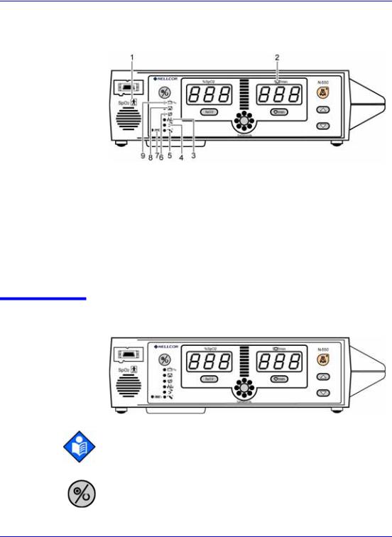
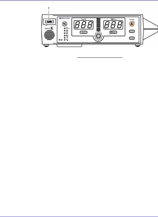
Identification of Front Panel Buttons and Symbols
|
Figure 1: Front Panel Buttons and Symbols |
||
1 |
— SpO2 Sensor Port |
12 |
— SatSeconds Alarm Limit |
|
|
|
Button |
2 |
— Power On/Off Button |
13 |
— SpO2 Alarm Limit Button |
|
|
|
|
3 |
— %SpO2 Display |
14 |
— Motion Indicator |
|
|
|
|
4 |
— Pulse Amplitude |
15 |
— Sensor Off Indicator |
|
Indicator |
|
|
5 |
— Pulse Rate Display |
16 |
— Sensor Message Indicator |
|
|
|
|
6 |
— Alarm Silence Button |
17 |
— Pulse Search Indicator |
|
|
|
|
7 |
— Alarm Silence Indicator |
18 |
— Data In Sensor Indicator |
|
|
|
|
8 |
— Adjust Up Button |
19 |
— Low Battery Indicator |
|
|
|
|
9 |
— Adjust Down Button |
20 |
— AC Power Indicator |
|
|
|
|
10 — Pulse Rate Alarm Limit |
21 |
— Speaker |
|
|
Button |
|
|
11 — SatSecondsTM Display |
|
|
|
N-550 |
7 |

Description of Controls, Indicators, and Symbols
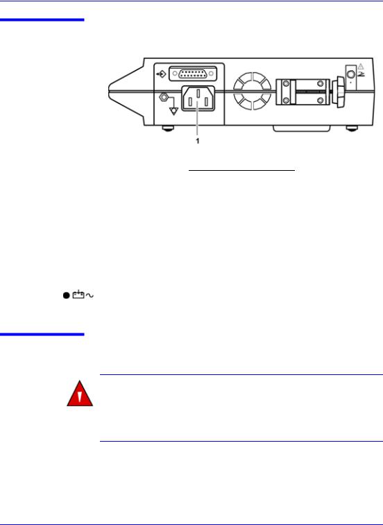
Identification of Rear Panel Components
1 |
— Data Port Connector |
3 |
— AC Power Connector |
|
|
|
|
2 |
— Foot Switch and Visual |
4 |
— Equipotential Connector |
|
Alarm Connector |
|
(ground) |
|
|
|
|
Figure 2: Rear Panel Symbols
N-550 Symbols
The symbols that are located on the rear panel of the N-550 are as follows:
1 — Data Interface |
3 |
— Foot Switch |
|
|
|
2 — Caution - Do not connect |
4 |
— Equipotential Terminal |
while power is on |
|
(ground) |
|
|
|
8
Description of Controls, Indicators, and Symbols
The symbols that are located on the front panel of the N-550 are as follows:
1 — Type BF Applied Part - |
6 |
— Pulse Search |
|
|
Not Defibrillator Proof |
|
|
|
|
|
|
2 |
— Pulse Rate |
7 |
— Data In Sensor |
|
|
|
|
3 |
— Motion |
8 |
— Low Battery |
|
|
|
|
4 |
— Sensor Off |
9 |
— AC Power/Battery Charge |
|
|
|
|
5 |
— Sensor Message |
|
|
|
|
|
|
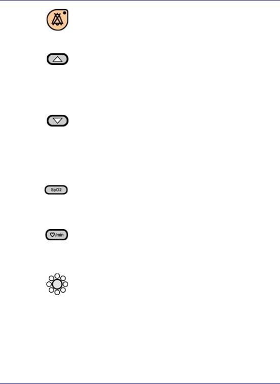
Description of Controls
Note: Each button press, except the Power On/Off button, should result in either a valid or an invalid button tone. If the button pressed fails to emit a tone, contact qualified service personnel.
The Power On/Off button is used to turn the N-550 on or off.
N-550 |
9 |
Description of Controls, Indicators, and Symbols
The Alarm Silence button is used to silence current alarms for the alarm silence duration period. When an alarm has been silenced, pressing the button again reactivates, or “unsilences” the alarm. It is also used to view and adjust alarm silence duration and alarm volume.
The Adjust Up button is used to increase alarm limit values, alarm silence duration, pulse beep volume, alarm volume, and data port baud rate. The Adjust Up button is used to select the communication protocol and time settings. Press the Adjust Up button one time to increase the display by one digit. Holding the Adjust Up button down for more than one second cause the display digits to scroll.
The Adjust Down button is used to decrease alarm limit values, alarm silence duration, pulse beep volume, alarm volume, and data port baud rate. The Adjust Down button is used to select the communication protocol and time settings. Press the Adjust Down button one time to decrease the display by one digit. Holding the Adjust Down button down for more than one second cause the display digits to scroll.
The SpO2 Alarm Limit button is used to view the SpO2 alarm limit. When the SpO2 Alarm Limit button is pressed at the same time as the Pulse Rate Alarm Limit button for approximately three seconds, the menu options are enabled.
The Pulse Rate Alarm Limit button is used to view the pulse rate alarm limit. When the Pulse Rate Alarm Limit button is pressed at the same time as the SpO2 Alarm Limit button for approximately three seconds, the menu options are enabled.
The SatSeconds Alarm Limit button is used to view the SatSeconds alarm limit. When pressed, the menu options are enabled. The Adjust Up and Adjust Down buttons are used to change the SatSeconds limit settings.
10
Description of Controls, Indicators, and Symbols
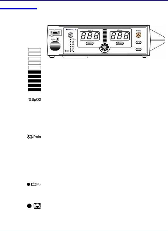
Description of Displays and Indicators
The Pulse Amplitude Indicator (blip bar). A 10-segment LED that indicates pulse beat and shows the relative pulse amplitude. As the detected pulse becomes stronger, more bars light with each pulse.
The %SpO2 Display. Shows the saturation level of oxygenated hemoglobin. The display value flashes zero during loss-of-pulse alarms and flashes the SpO2 value when the SpO2 is outside the alarm limits. During pulse search, the N-550 continues to update the display. If alarm limits have been changed from their power-on defaults, a decimal point (.) is displayed after the SpO2 value (100.).
The Pulse Rate Display. Shows the pulse rate in beats per minute. It flashes zeros during loss-of-pulse alarms and flashes the beats per minute value in red when the pulse rate is outside of the alarm limit. During pulse search, the N-550 continues to update the display. Pulse rates outside of the pulse rate range (20 to 250 bpm) are displayed as the closest value within the range. If alarm limits have been changed from their power-on defaults, a decimal point (.) is displayed after the pulse rate value (112.).
The AC Power Indicator. Lights continuously when the N-550 is connected to AC power. It also indicates that the battery is charging. It is off when the N-550 is being powered by its internal battery.
The Low Battery Indicator. Lights continuously to indicate that 15 or fewer minutes of battery capacity remain. The Low Battery indicator flashes when the battery is critically low.
N-550 |
11 |

Description of Controls, Indicators, and Symbols
The Alarm Silence Indicator. Lights continuously when an audible alarm has been silenced. It flashes when the alarm silence duration has been set to OFF.
The Motion Indicator. Lights continuously whenever the OXIMAX® algorithm detects the presence of artifact independent of its severity or the impact on the SpO2 or pulse rate values. Whenever the motion indicator and the pulse search indicator are simultaneously lit, it is an indication that the artifact is significant and/or has been persistent.
The Pulse Search Indicator. Lights continuously prior to initial acquisition of a pulse signal and during prolonged and challenging monitoring conditions. It flashes during a loss-of-pulse signal.
The Sensor Off Indicator is lit when either the sensor is invalid, or no longer on the patient’s finger. It usually indicates that the sensor is not on the patient.
The Sensor Message Indicator. Lights when the N-550 cannot determine an SpO2 level or a pulse rate. The Sensor Message recommendations for improving the signal are:
•Reposition sensor
•Check or change adhesive wrap
•Choose alternate site
•Warm site
•Cover sensor
•Use forehead, nasal, or ear sensor (adult patients only)
•Use OXIMAX adhesive sensor
•Secure cable
•Secure with headband (MAX-FAST)
•Remove nail polish
•Loosen sensor (too tight)
•Isolate external interference (electrosurgical device, cell phone)
•Clean site (MAX-R)
12
Description of Controls, Indicators, and Symbols
The Data In Sensor Indicator. The indicator blinks for approximately one minute when initially connected to the N-550 to indicate that the attached OXIMAX sensor contains a patient sensor event record. The indicator lights continuously to indicate that the attached sensor memory is full. The indicator does not light when there is no data in the sensor, even though a valid sensor is connected to the N-550.
The SatSecondsTM Indicator. Fills in clockwise as the SatSeconds alarm management approaches the SatSeconds alarm limit threshold. All segments of the SatSeconds indicator flash during a SatSeconds alarm. When a SatSeconds setting other than OFF is selected, the green LED at the top of the SatSeconds indicator will light. The green LED at the 12-o'clock position indicates that SatSeconds alarm management is engaged.
Description of Audible Indicators
Following are descriptions of N-550 audible indicators.
Power-On Self-Test |
A 1-second tone indicating that the N-550 |
Pass |
has been turned on and has successfully |
|
completed the power-on self-test |
|
|
Valid Button Press |
A short, medium-pitched tone indicating |
|
that an appropriate button has been |
|
pressed |
|
|
Invalid Button Press |
A short, low-pitched tone indicating that a |
|
button has been pressed that is not |
|
appropriate for the current state of the |
|
N-550 |
|
|
High Priority Alarm |
A high-pitched, fast-pulsating tone |
|
indicating loss of pulse with no patient |
|
motion |
|
|
Medium Priority |
A medium-pitched, normal-pulsating tone |
Alarm |
indicating an SpO2 or pulse rate limit |
|
violation |
|
|
N-550 |
13 |

Description of Controls, Indicators, and Symbols
Low Priority Alarm |
A low-pitched, slow-pulsating tone |
|
indicating a sensor disconnect, low |
|
battery, or N-550 failure |
|
|
Alarm Silence |
Three beeps that sound approximately |
Reminder |
every 3 minutes when alarms are silenced |
|
with the alarm silence duration set to OFF |
|
|
Pulse Beep |
A single beep sounds for each detected |
|
pulse. The pitch changes as monitored |
|
SpO2 values increase or decrease. |
|
|
Volume Setting Tone |
A continuous tone that is used to adjust |
|
the alarm volume |
|
|
Confirmation Tone |
Three beeps sound to indicate that default |
|
settings have been saved or reset to |
|
factory defaults or trend data has been |
|
deleted |
|
|
14

S e t t i n g u p t h e N - 5 5 0
WARNING: Explosion hazard. Do not use the N-550 pulse oximeter in the presence of flammable anesthetics or gases.
WARNING: Pulse oximetry readings and pulse signals can be affected by certain ambient environmental conditions, sensor application errors, and certain patient conditions. See the appropriate sections of the manual for specific safety information.
WARNING: To ensure patient safety, do not place the N-550 in any position that might cause it to fall on the patient.
WARNING: As with all medical equipment, carefully route patient cabling to reduce the possibility of patient entanglement or strangulation.
WARNING: Disconnect the N-550 and Nellcor sensor from the patient during magnetic resonance imaging (MRI) scanning. Induced current could potentially cause burns. The N-550 may affect the MRI image; the MRI unit may affect the accuracy of oximeter measurements.
WARNING: To ensure accurate performance and prevent device failure, do not subject the N-550 to extreme moisture, such as direct exposure to rain. Such exposure may cause inaccurate performance or device failure.
N-550 |
15 |
Setting up the N-550
WARNING: Do not use an N-550, sensor, cables, or connectors that appear to be damaged.
WARNING: The N-550 is not defibrillator-proof. However, it may remain attached to the patient during defibrillation or while an electrosurgical unit is in use, but the readings may be inaccurate during use and shortly thereafter.
WARNING: In the USA, do not connect the N-550 to an electrical outlet controlled by a wall switch because the N-550 may be accidentally turned off.
WARNING: Use only the DOC-10 pulse oximetry cable with the N-550. Use of another sensor cable will have an adverse effect on performance. Do not attach any cable that is intended for computer use to the sensor port. Do not connect any device other than a Nellcor-approved sensor to the sensor connector.
List of Components
1 — N-550 Pulse Oximeter
1 — Nellcor Sensor or Assortment Pack
1 — DOC-10 Pulse Oximeter Cable
1 — N-550 Operator's Manual
1 — Hospital-Grade Power Cord or power cord appropriate for country of sale
1 — Sensor Accuracy Grid
1 — Quick Guide
16
Setting up the N-550
Connecting the N-550 to AC Power
1 — Power Connector
1.Plug the female connector of the power cord into the N-550 AC power connector (1).
2.Plug the male connector of the power cord into a properly grounded AC outlet.
3. Verify that the AC POWER INDICATOR is lit.
Connecting a Sensor to the N-550
WARNING: Use only the DOC-10 pulse oximetry cable with the N-550. Use of another sensor cable will have an adverse effect on performance. Do not attach any cable that is intended for computer use to the sensor port. Do not connect any device other than a Nellcor-approved sensor to the sensor connector.
N-550 |
17 |
Setting up the N-550
.
1 — SpO2 Sensor Port
1.Connect a DOC-10 pulse oximetry cable to the SpO2 Sensor Port
(1) on the front of the N-550.
2.Connect an SpO2 Sensor to the other end of the DOC-10 pulse oximetry cable. Plug the sensor connector firmly into the DOC-10 pulse oximetry cable.
18

B a t t e r y O p e r a t i o n
WARNING: Dispose of an old battery by following local guidelines for disposal of lead acid batteries.
Operating the N-550 on Battery Power
The N-550 has an internal battery that may be used to power the N-550 during transport or when AC power is not available. A new, fully charged battery will provide at least 1.5 to 2 hours of monitoring time under the following conditions: no audible alarms sound and no serial output devices are attached.
Note: Whenever the N-550 is connected to AC power, the battery is being charged. Therefore, it is recommended that the N-550 remain connected to AC power when not in use. This will make a fully charged battery available for use at any time.
The N-550 cannot operate with a dead battery (even when plugged in). Before attempting to turn on an N-550 with a depleted battery, first plug the N-550 into an AC outlet to allow the battery to charge for a few minutes. The N-550 may then be powered on.
To charge a low or dead battery, connect the N-550 to AC power. A full charge of a dead battery takes 11 hours while the N-550 is turned off or 12 hours while the N-550 is on.
When all of the following conditions are present for 15 minutes, the
N-550 will automatically shut down:
•N-550 is running on battery power
•No buttons have been pressed
•No pulse has been detected (for example, when no patient is connected to the sensor or the sensor is disconnected)
N-550 |
19 |
Battery Operation
•No alarms are present (other than low battery or a non-correctable error)
Low Battery Indicator
The Low Battery Indicator lights and a low priority alarm begins to sound when 15 minutes but not more than 20 minutes of monitoring time remain on the existing battery charge. This alarm cannot be silenced while running on battery power. Connecting the N-550 to AC power will silence the alarm. If the N-550 is not connected to AC power within approximately 15 minutes, the N-550 will shut off.
Note: As the battery is used and recharged over a period of time, the amount of time between the onset of the low battery alarm and the N-550 shut-off may become shorter.
It is recommended that qualified service personnel replace the internal battery every 24 months.
CAUTION: If the N-550 is to be stored for 2 months or longer, notify service personnel to remove the battery from the N-550 prior to storage. Recharge the battery when it has not been charged for 2 or more months.
The Low Battery Indicator flashes and a high priority alarm begins to sound when the battery reaches the lowest battery voltage at which an N-550 can support normal operation. This alarm cannot be silenced while running on battery power. If the N-550 is not connected to AC power, the N-550 will shut off after 10 seconds.
20

U s i n g t h e N - 5 5 0
Turning on the N-550
Discussion
Before using the N-550 in a clinical setting, you must verify that the N-550 is working properly and is safe to use. Proper working condition can be verified by successful completion of the Power-On Self-Test (POST), described in the following section.
WARNING: The N-550 should not be used adjacent to or stacked with other equipment. If adjacent or stacked use is necessary, the N-550 should be observed to verify normal operation in the configuration in which it is used.
CAUTION: If any indicator or display element does not light, or the speaker does not sound, do not use the N-550. Instead, contact qualified service personnel, your local Nellcor representative, or Nellcor's Technical Services Department, 1.800.635.5267.
Note: The N-550 should complete the POST function within 12 seconds.
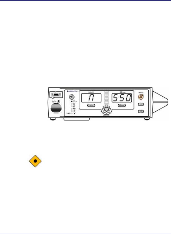
Procedure
1.Turn on the N-550 by pressing and holding the Power On/Off button for more than one second.
N-550 |
21 |
Using the N-550
2. The N-550 displays/sounds:
|
Display |
Sound |
|
|
|
5 |
(in pulse rate left window) |
one beep tone |
|
|
|
5 |
(in pulse rate center window) |
one beep tone |
|
|
|
0 |
(in pulse rate right window) |
one beep tone |
|
|
|
n (in SpO2 left window) |
none |
|
|
|
|
n (in SpO2 center window) |
none |
|
|
|
|
3.The N-550 automatically starts the Power-On Self-Test (POST), which tests N-550 circuitry and functions.
CAUTION: During POST (immediately after power-up), confirm that all display segments and indicators light, and the speaker sounds a 1-second pass tone.
4.While performing POST, the self-test display appears for approximately 2 to 4 seconds. During this time:
•All indicators illuminate
•All segments of all numeric digits light and change from red to green
22
Loading...