


 Loading...
N-595 |
Pulse Oximeter |
Operator’s Manual |

Nellcor Puritan Bennett Inc. is an affiliate of Tyco Healthcare. Nellcor, Oxiband, Durasensor, OxiCliq, Dura-Y, MAX-FAST, and OXIMAX are trademarks of Nellcor Puritan Bennett Inc.
This ISM device complies with Canadian ICES-001.
Cet appareil ISM est conforme à la norme NMB-001 Canada.
To obtain information about a warranty, if any, contact Nellcor’s Technical Services Department, or your local representative.
Purchase of this instrument confers no express or implied license under any Nellcor Puritan Bennett patent to use the instrument with any sensor that is not manufactured or licensed by Nellcor Puritan Bennett.
Covered by one or more of the following U.S. Patents and foreign equivalents: 4,621,643; 4,653,498; 4,700,708; 4,770,179; Re. 35,122; 4,802,486; 4,869,254; 4,928,692; 4,934,372; 5,078,136; 5,351,685; 5,368,026; 5,485,847; 5,533,507; 5,662,106; and 5,853,364.

C o n t e n t s
Contents . . . . . . . . . . . . . . . . . . . . . . . . . . . . . . . . . . . . . . . . . . . . . . . . . . . . . . i Figures . . . . . . . . . . . . . . . . . . . . . . . . . . . . . . . . . . . . . . . . . . . . . . . . . . . . . . vi
Tables . . . . . . . . . . . . . . . . . . . . . . . . . . . . . . . . . . . . . . . . . . . . . . . . . . . . . . . vi
Safety Information and Introduction
Safety Information . . . . . . . . . . . . . . . . . . . . . . . . . . . . . . . . . . . . . . . . . . . . . 1
Warnings ........................................................................................... |
1 |
Cautions ............................................................................................ |
2 |
Introduction . . . . . . . . . . . . . . . . . . . . . . . . . . . . . . . . . . . . . . . . . . . . . . . . . . 5
Intended Use for the N-595 ............................................................... |
5 |
How to Use this Manual .................................................................... |
6 |
Using the N-595
Description of Controls, Indicators, and Symbols . . . . . . . . . . . . . . . . . . . . . . 7
Identification of Front Panel Buttons and Symbols |
...........................7 |
Identification of Rear Panel Components .......................................... |
8 |
N-595 Symbols .................................................................................. |
8 |
Description of Controls ...................................................................... |
9 |
Description of Displays and Indicators ............................................ |
10 |
Description of Audible Indicators ..................................................... |
14 |
Setting up the Monitor . . . . . . . . . . . . . . . . . . . . . . . . . . . . . . . . . . . . . . . . . 15
List of Components ......................................................................... |
17 |
Connecting the N-595 to AC Power ................................................ |
17 |
Connecting an OXIMAX Sensor to the N-595 .................................. |
19 |
Battery Operation . . . . . . . . . . . . . . . . . . . . . . . . . . . . . . . . . . . . . . . . . . . . 21
Operating the N-595 on Battery Power ........................................... |
21 |
Low Battery Indicator ...................................................................... |
22 |
Using the Monitor . . . . . . . . . . . . . . . . . . . . . . . . . . . . . . . . . . . . . . . . . . . . 27
Introduction .................................................................................... |
27 |
N-595 |
i |

Contents
Turning On the Monitor ................................................................... |
29 |
OXIMAX Sensor Attached ..................................................... |
31 |
No OXIMAX Sensor Attached ................................................ |
33 |
Turning the Backlight On or Off ...................................................... |
34 |
Adjusting Screen Contrast .............................................................. |
34 |
Selecting the Pleth View ................................................................. |
34 |
Selecting the Blip View ................................................................... |
35 |
Setting the Pulse Beep Volume ...................................................... |
36 |
Setting the Alarm Volume ............................................................... |
36 |
Setting the Date and Time .............................................................. |
37 |
Setting Alarm Silence Duration ....................................................... |
38 |
Disabling Audible Alarms ................................................................ |
39 |
Selecting Standby Mode ................................................................. |
41 |
Adult-Pediatric or Neonatal Settings ............................................... |
42 |
Setting Patient Adult-Pediatric/Neonatal Mode .................... |
42 |
Alarm Limit Changed Indicator ....................................................... |
44 |
Setting Alarm Limits ........................................................................ |
44 |
Setting SatSeconds Alarm Limit ..................................................... |
46 |
Setting Monitor Response Mode .................................................... |
47 |
Selecting the Display Language ..................................................... |
48 |
OXIMAX Sensor Messages .............................................................. |
49 |
OXIMAX Sensor Adjust Condition Messages ........................ |
50 |
OXIMAX Sensor Adjust Messages ........................................ |
51 |
Monitor Trend . . . . . . . . . . . . . . . . . . . . . . . . . . . . . . . . . . . . . . . . . . . . . . . .53
Monitor Trend Data ........................................................................ |
53 |
Trend Data Operation ........................................................... |
55 |
Selecting the Trend Data Display Scale ......................................... |
55 |
Reading the Trend Data Display ..................................................... |
57 |
Dual Trend Data Display ................................................................. |
58 |
SpO2 Trend Display ....................................................................... |
59 |
Pulse Rate Trend Display ............................................................... |
59 |
Histogram Trend Data Display ........................................................ |
60 |
Pulse Amplitude Trend Data Display .............................................. |
61 |
Clearing Trend Information ............................................................. |
62 |
Sensors and Accessories
OXIMAX Sensor Event Record . . . . . . . . . . . . . . . . . . . . . . . . . . . . . . . . . . . .65
Setting In-Sensor Data Type .......................................................... |
66 |
OXIMAX Sensor Type ...................................................................... |
68 |
OXIMAX Sensor Data Type ............................................................. |
68 |
OXIMAX Sensor Event Record Data Available ................................ |
69 |
ii

|
Contents |
OXIMAX Sensor Event Record Not Available .................................. |
70 |
OXIMAX Sensor Event Record Graphical Data ................................ |
71 |
Viewing and Printing OXIMAX Sensor Event History Data ............... |
73 |
OXIMAX Sensor Tabular Event Data ............................................... |
75 |
Viewing and Printing In-Sensor Tabular Event History Data ........... |
76 |
Printing . . . . . . . . . . . . . . . . . . . . . . . . . . . . . . . . . . . . . . . . . . . . . . . . . . . . . 79
Printing Monitor Trend Information .................................................. |
79 |
Monitor Trend Data in ASCII Mode ................................................. |
81 |
Trend Data in Graph Mode ............................................................. |
82 |
Real-Time Display/Printout Format ................................................. |
83 |
Column Headings ................................................................. |
85 |
Data Source .......................................................................... |
85 |
Software Version .................................................................. |
85 |
Alarm Limits .......................................................................... |
86 |
Monitor Mode ........................................................................ |
86 |
Response Mode .................................................................... |
86 |
Data Column Headings ......................................................... |
87 |
Time ...................................................................................... |
87 |
Patient Data .......................................................................... |
87 |
Operating Status ................................................................... |
88 |
Using the Data Port . . . . . . . . . . . . . . . . . . . . . . . . . . . . . . . . . . . . . . . . . . . 91
Overview ......................................................................................... |
91 |
Connecting to the Data Port ............................................................ |
91 |
Data Port Pinouts .................................................................. |
92 |
Data Port Setup ............................................................................... |
93 |
Using the Nurse Call Interface ........................................................ |
95 |
Setting Nurse Call RS-232 Polarity ....................................... |
96 |
Setting Nurse Call Relays Normally Open/Closed ................ |
97 |
Calculating the Analog Voltage Output ........................................... |
97 |
OXIMAX Sensors and Accessories . . . . . . . . . . . . . . . . . . . . . . . . . . . . . . . . 99
OXIMAX Sensor Event Record Data ................................................ |
99 |
Selecting an OXIMAX Sensor ........................................................... |
99 |
OXIMAX Sensor Features .............................................................. |
103 |
Biocompatibility Testing ................................................................ |
103 |
Optional Accessories .................................................................... |
103 |
GCX Mounting Plate ........................................................... |
105 |
GCX Poly-Mount (vertical wall mount with |
|
19-inch channel) ........................................................... |
106 |
GCX Poly-Mount (horizontal wall mount with rail adapter) .107 |
|
GCX Poly-Mount Roll Stand ............................................... |
108 |
GCX Utility Basket .............................................................. |
109 |
N-595 |
iii |

Contents
Soft-Sided Carrying Case ................................................... |
110 |
Performance Considerations . . . . . . . . . . . . . . . . . . . . . . . . . . . . . . . . . . . . 111
Performance Verification .............................................................. |
111 |
N-595 Monitor Performance Considerations ................................ |
111 |
Dysfunctional Hemoglobins ................................................ |
112 |
Anemia ............................................................................... |
112 |
Saturation ........................................................................... |
112 |
Pulse Rates ........................................................................ |
112 |
OXIMAX Sensor Performance Considerations .............................. |
113 |
Troubleshooting
Troubleshooting . . . . . . . . . . . . . . . . . . . . . . . . . . . . . . . . . . . . . . . . . . . . . . 117
Error Codes .................................................................................. |
117 |
Prompts and Error Messages ....................................................... |
119 |
Corrective Action .......................................................................... |
122 |
EMI (Electro-magnetic Interference) ............................................. |
125 |
Obtaining Technical Assistance .................................................... |
126 |
OXIMAX Sensor Message Setup ................................................... |
127 |
Maintenance . . . . . . . . . . . . . . . . . . . . . . . . . . . . . . . . . . . . . . . . . . . . . . . .129
Returning the N-595 ..................................................................... |
129 |
Service .......................................................................................... |
129 |
Periodic Safety Checks ................................................................. |
130 |
Cleaning ........................................................................................ |
130 |
Menu Structure . . . . . . . . . . . . . . . . . . . . . . . . . . . . . . . . . . . . . . . . . . . . . .131
N-595 Menu Description ............................................................... |
131 |
Technical Information
SatSeconds . . . . . . . . . . . . . . . . . . . . . . . . . . . . . . . . . . . . . . . . . . . . . . . .135
Describing SatSeconds ................................................................ |
135 |
SatSeconds “Safety Net” .............................................................. |
137 |
SatSeconds Display ...................................................................... |
137 |
Factory Defaults . . . . . . . . . . . . . . . . . . . . . . . . . . . . . . . . . . . . . . . . . . . . .139
Neonate Default Settings .............................................................. |
139 |
Adult Default Settings ................................................................... |
140 |
iv

Contents
Principles of Operation . . . . . . . . . . . . . . . . . . . . . . . . . . . . . . . . . . . . . . . 143
Oximetry Overview ....................................................................... |
143 |
Automatic Calibration .......................................................... |
144 |
Functional versus Fractional Saturation ............................. |
144 |
Measured versus Calculated Saturation ............................. |
145 |
OXIMAX Technology ...................................................................... |
145 |
Specifications . . . . . . . . . . . . . . . . . . . . . . . . . . . . . . . . . . . . . . . . . . . . . . 147
Performance ................................................................................. |
147 |
Electrical ........................................................................................ |
148 |
Environmental Conditions ............................................................. |
149 |
Physical Characteristics ................................................................ |
151 |
Compliance ................................................................................... |
152 |
Manufacturer’s Declaration ........................................................... |
155 |
Index . . . . . . . . . . . . . . . . . . . . . . . . . . . . . . . . . . . . . . . . . . . . . . . . . . . . . . 167
N-595 |
v |

Contents
F i g u r e s
Figure 1: |
Front Panel Buttons and Symbols ............................. |
7 |
Figure 2: |
Rear Panel Components ........................................... |
8 |
Figure 3: |
ASCII Mode Printout ............................................... |
82 |
Figure 4: |
Graph Mode Printout ............................................... |
83 |
Figure 5: |
Real-Time Printout ................................................... |
84 |
Figure 6: |
Data Port Pin Layout ................................................ |
93 |
Figure 7: |
GCX Mounting Plate .............................................. |
105 |
Figure 8: |
GCX Poly-Mount (vertical wall mount with |
|
|
19-inch channel) .................................................... |
106 |
Figure 9: |
GCX Poly-mount (horizontal wall mount with |
|
|
rail adapter) ............................................................ |
107 |
Figure 10: |
GCX Poly-mount Roll Stand .................................. |
108 |
Figure 11: |
GCX Utility Basket ................................................. |
109 |
Figure 12: |
Soft-Sided Carrying Case ...................................... |
110 |
Figure 13: |
Alarm Response with SatSeconds ........................ |
136 |
Figure 14: |
Oxyhemoglobin Dissociation Curve ....................... |
145 |
vi

Contents
Ta b l e s
Table 1: |
Audible Indicators .................................................... |
14 |
Table 2: |
Low Battery and Critical Battery .............................. |
23 |
Table 3: |
Parameter Ranges ................................................... |
27 |
Table 4: |
Reading Trend Display ............................................ |
57 |
Table 5: |
Data Port Pinouts ..................................................... |
92 |
Table 6: |
Analog Pinouts ......................................................... |
97 |
Table 7: |
Nellcor OXIMAX Sensor Models and |
|
|
Patient Sizes .......................................................... |
101 |
Table 8: |
OXIMAX Sensor Features ..................................... |
103 |
Table 9: |
Error Codes ........................................................... |
118 |
Table 10: |
Prompt/Error Messages ......................................... |
120 |
Table 11: |
Neonate Factory Defaults ...................................... |
139 |
Table 12: |
Adult Factory Defaults ........................................... |
140 |
Table 13: |
Electromagnetic Emissions .................................... |
155 |
Table 14: |
Electromagnetic Immunity ..................................... |
156 |
Table 15: |
Electromagnetic Immunity, RF Portable |
|
|
Equipment .............................................................. |
159 |
Table 16: |
Recommended Separation Distances ................... |
161 |
Table 17: |
Cables .................................................................... |
162 |
N-595 |
vi |
S a f e t y I n f o r m a t i o n
Warnings
Warnings are identified by the WARNING symbol shown above.
Warnings alert the user to potential serious outcomes (death, injury, or adverse events) to the patient or user.
WARNING: The sensor extrapolates from the date and time provided by the N-595 when recording the sensor event record to the sensor. The accuracy of the date/time is the responsibility of the N-595. It is recommended that the N-595 user set the time/ date to the correct value before a sensor event record-enabled sensor is connected, and that this date/time not be changed while the sensor remains connected. Since a sensor with sensor event record data can be transported from one monitor to another, having discrepancies in the date/time between monitors and the sensor event record data will affect the order the sensor event record data appears. To eliminate this possible problem, all monitors within an institution should be set to the same time.
WARNING: Explosion hazard. Do not use the N-595 pulse oximeter in the presence of flammable anesthetics or gases.
WARNING: Chemicals from a broken LCD display panel are toxic when ingested. Use caution when handling a pulse oximeter with a broken display panel.
N-595 |
1 |

Safety Information
WARNING: Pulse oximetry readings and pulse signals can be affected by certain environmental conditions, OXIMAX sensor application errors, and certain patient conditions. See the appropriate sections of this manual for specific safety information.
WARNING: The use of accessories, sensors, and cables other than those specified may result in increased emission and/or decreased immunity and inaccurate readings of the N-595 pulse oximeter.
WARNING: Failure to cover the OXIMAX sensor site with opaque material in high ambient light conditions may result in inaccurate measurements.
Cautions
Cautions are identified by the CAUTION symbol shown above.
Cautions alert the user to exercise care necessary for the safe and effective use of the N-595 pulse oximeter.
2

Safety Information
Caution: When connecting the N-595 to any instrument, verify proper operation before clinical use. Both the N-595 and the instrument connected to it must be connected to a grounded outlet. Accessory equipment connected to the pulse oximeter’s data interface must be certified according to IEC Standard 950 for data-processing equipment or IEC Standard 60601-1 for electromedical equipment. All combinations of equipment must be in compliance with IEC Standard 60601-1-1 systems requirements. Anyone who connects additional equipment to the signal input port or signal output port (N-595 data port connector) configures a medical system and is therefore responsible for ensuring that the system complies with the requirements of system standard IEC Standard 60601-1-1 and the electromagnetic compatibility system standard IEC Standard 60601-1-2. The N-595 accuracy may degrade if it is connected to secondary I/O devices when the instrument is not connected to earth reference.
Caution: Federal law (U.S.A.) restricts this device to sale by or on the order of a physician.
Caution: Dispose of battery in accordance with local requirements and regulations.
N-595 |
3 |

I n t r o d u c t i o n
WARNING: The N-595 is intended only as an adjunct in patient assessment. It must be used in conjunction with clinical signs and symptoms.
Intended Use for the N-595
The N-595 pulse oximeter is indicated for the continuous non-invasive monitoring of functional oxygen saturation of arterial hemoglobin (SpO2) and pulse rate. The N-595 is intended for use with neonatal, pediatric, and adult patients during both no motion and motion conditions and for patients who are well or poorly perfused, in hospitals, hospital-type facilities, intra-hospital transport, and home environments. For prescription use only.
Note: Hospital use typically covers such areas as general care floors, operating rooms, special procedure areas, intensive and critical care areas, within the hospital plus hospital-type facilities.
Hospital-type facilities include physician office based facilities, sleep labs, skilled nursing facilities, surgicenters, and sub-acute centers.
Intra-hospital transport includes transport of a patient within the hospital or hospital-type facility.
Home Care use is defined as managed/used by a lay person (parent or other similar non-critical caregiver) in the home environment.
Use with any particular patient requires the selection of an appropriate oxygen OXIMAX sensors as described in this Operator's Manual.
N-595 |
5 |

Introduction
Motion performance claims are applicable to models MAX-A, MAX-AL, MAX-P, MAX-N, and MAX-I Nellcor OXIMAX TM oximetry sensors.
How to Use this Manual
All users should read this manual thoroughly. More experienced users of the N-595 will be able to go to the topics for the information they require.
The current copy of this manual is available on the internet at:
http://www.mallinckrodt.com/respiratory/resp/Serv_Supp/ProductManuals.html
6

D e s c r i p t i o n o f C o n t r o l s , I n d i c a t o r s , a n d S y m b o l s
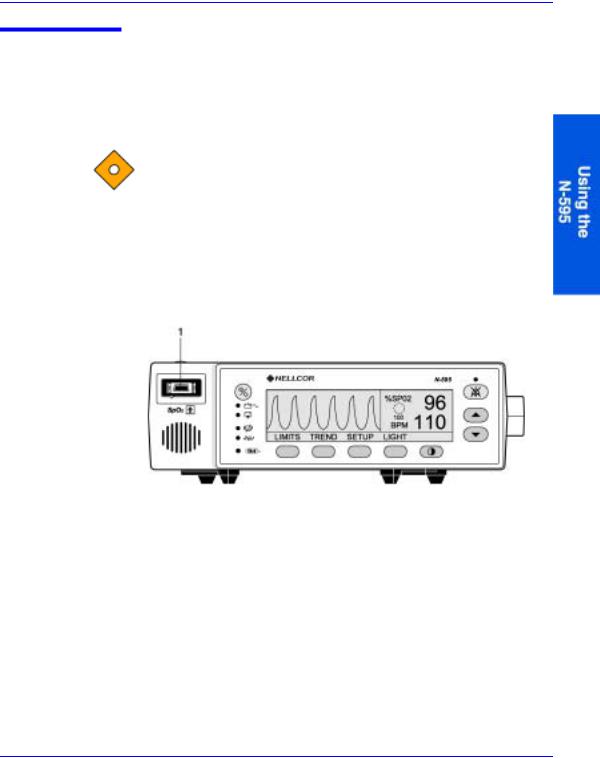
Identification of Front Panel Buttons and Symbols
1. |
SpO2 OXIMAX Sensor Port, page 19 |
12. ADJUST DOWN Button, page 10 |
|
2. |
AC Power Indicator, page 12 |
13. |
Neonate Mode Indicator, page 13 |
3. |
ON/STANDBY Button, page 9 |
14. |
CONTRAST Button, page 10 |
4. |
Low Battery Indicator, page 12 |
15. |
Fast Response Mode Indicator, page 13 |
5. |
Waveform Display, page 10 |
16. |
Softkeys, page 10 |
6. |
SatSecondsTM Indicator, page 13 |
17. |
Menu Bar, page 10 |
7. |
%SpO2 Display, page 12 |
18. |
Data In Sensor Indicator, page 13 |
8. |
Pulse Rate Display, page 12 |
19. |
Motion Indicator, page 12 |
9. |
Alarm Silence Indicator, page 12 |
20. |
Pulse Search Indicator, page 13 |
10. ALARM SILENCE Button, page 9 |
21. Speaker |
||
11. ADJUST UP Button,page 10 |
|
|
|
Figure 1: Front Panel Buttons and Symbols
N-595 |
7 |
Description of Controls, Indicators, and Symbols
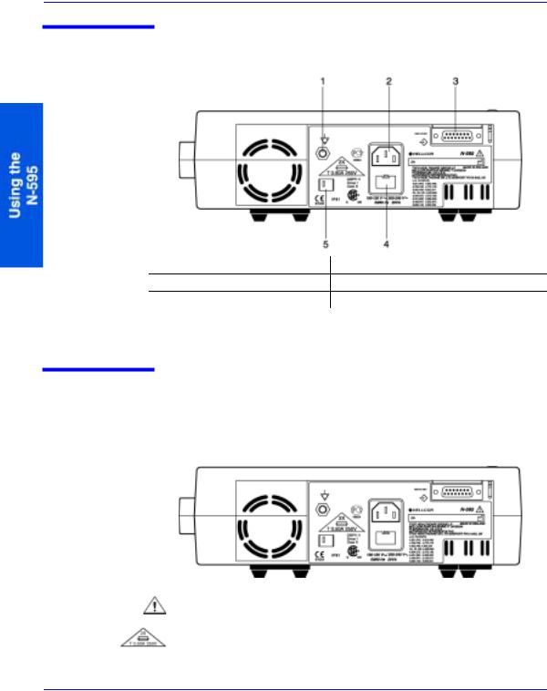
Identification of Rear Panel Components
1.Equipotential Terminal (Ground) 4. Fuse Holder
2.AC Power Connector, page 17 5. Supply Voltage Selector Switch, page 17
3.Data Port Connector, page 91
Figure 2: Rear Panel Components
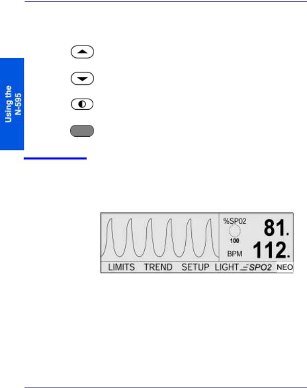
N-595 Symbols
The symbols that are located on the rear panel of the N-595 are as follows:
See Instructions for Use
Fuse Replacement
8

Description of Controls, Indicators, and Symbols
Equipotential Terminal (ground)
Date of Manufacture
Data Interface
There is one symbol located on the front panel of the N-595.
Type BF Applied Part - Not defibrillator proof.
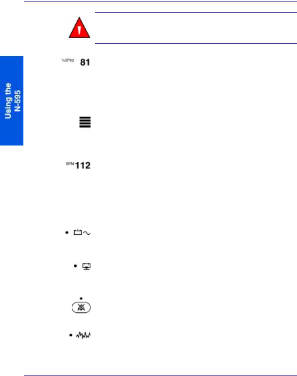
Description of Controls
Note: A button press, except the ON/STANDBY button, should result in either a valid or an invalid key tone (refer to Table 1 on page 14). If the key pressed fails to emit a tone, contact qualified service personnel.
The ON/STANDBY button. Used to turn the N-595 monitor on or off.
The ALARM SILENCE button. Used to silence current alarms for the alarm silence duration period. When an alarm has been silenced, pressing the button again reactivates, or “unsilences” the alarm. It is also used to view and adjust alarm silence duration and alarm volume.
N-595 |
9 |
Description of Controls, Indicators, and Symbols
The ALARM SILENCE button clears “SENSOR OFF,” “LOW BATTERY,” and “SENSOR DISCONNECT” messages from the display.
The ADJUST UP button. Used to increase variable parameters of the monitor.
The ADJUST DOWN button. Used to decrease variable parameters in the monitor.
The CONTRAST button. Used in conjunction with the ADJUST UP and ADJUST DOWN buttons to lighten or darken the display screen.
The softkey buttons have multiple uses depending on the legend displayed above the button.
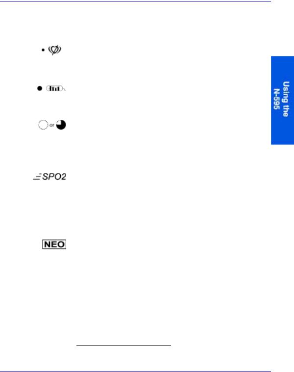
Description of Displays and Indicators
The type of display is user selectable. Refer to Selecting the Pleth
View on page 34.
The pleth display includes a “wiper bar” plethysmographic waveform, menu bar, and current measured %SpO2 and pulse rate. If SatSeconds are enabled, the pleth display includes the SatSeconds indicator and SatSeconds setting. A decimal point after the %SpO2 or
10
Description of Controls, Indicators, and Symbols
pulse rate indicate that the respective limits have been changed from the power on defaults (Monitor Trend Data on page 53).
The blip display includes a pulse amplitude blip bar, current measured %SpO2 and pulse rate, and current upper and lower %SpO2 and pulse rate limits. If SatSeconds are enabled, the blip display includes the SatSeconds indicator and SatSeconds setting. Decimal points after the %SpO2 or pulse rate indicate that the respective limits have been changed from the power-on defaults.
There are various matrixes within the OXIMAX algorithm. Some of these, are used to assess the severity of conditions presented to the N-595 in measuring SpO2 and pulse rate on a patient. These individual matrices or combinations of these matrices are used to drive the LED indicators on the N-595 front panel.
The OxiMax algorithm automatically extends the amount of data required for measuring SpO2 and pulse rate depending on the measurement conditions. During normal measurement conditions the averaging time is 6-7 seconds. During challenging measurement conditions which could be caused by low perfusion, motion, external interference like ambient light, or a combination of these, the OXIMAX algorithm automatically extends the amount of data required beyond 7 seconds. If the resulting dynamic averaging time exceeds 20 seconds, the pulse search indicator is lit solid and SpO2 and Pulse Rate will continue to be updated every second. As these conditions become even more challenging, the amount of data required continues to extend. If the dynamic averaging time reaches 40 seconds, the pulse search indicator begins flashing, the SpO2 and pulse rate displays flash zeros indicating a loss-of-pulse condition.
N-595 |
11 |
Description of Controls, Indicators, and Symbols
WARNING: Failure to cover the OXIMAX sensor site with opaque material in high ambient light conditions may result in inaccurate measurements.
The %SpO2 Display. Shows the hemoglobin oxygen saturation level. The display value flashes zeros during loss-of-pulse alarms and flashes the SpO2 value when the SpO2 is outside the alarm limits. During Pulse Search, the monitor continues to update the display. If alarm limits have been changed from their power-on defaults, a decimal point (.) is displayed after the SpO2 value (81.).
The Pulse Amplitude Indicator (blip bar). Indicates pulse beat and shows the relative pulse amplitude. As the detected pulse becomes stronger, more bars light with each pulse. This indicator is available only in the blip view.
The Pulse Rate Display. Shows the pulse rate in beats per minute. It flashes during loss-of-pulse alarms and when the pulse rate is outside of the alarm limits. During Pulse Search, the monitor continues to update the display. Pulse rates outside of the pulse rate range (20 to 250 bpm) are displayed as the closest value within the range. If alarm limits have been changed from their power-on defaults, a decimal point (.) is displayed after the BPM value (112.).
The AC Power Indicator. Lights continuously when the N-595 is connected to AC power. It also indicates that the battery is charging. It is off when the monitor is being powered by internal battery.
The Low Battery Indicator. Lights continuously when 15 or fewer minutes of battery capacity remain. Flashes when the battery capacity reaches critical condition.
The Alarm Silence Indicator. Lights continuously when an audible alarm has been silenced. It flashes when the alarm silence duration has been set to Off.
The Motion Indicator. The motion indicator is lit whenever the
OXIMAX algorithm detects the presence of artifacts1 independent of its severity or the impact on the SpO2 or pulse rate values. When the
12
Description of Controls, Indicators, and Symbols
motion indicator and the pulse search indicator are simultaneously lit, it is an indication that the artifact is significant and/or has been persistent.
The Pulse Search Indicator. Lights continuously prior to initial acquisition of a pulse signal and during prolonged and challenging monitoring conditions. The pulse search indicator flashes during a loss-of-pulse signal.
The Data In-Sensor Indicator. Lights to indicate that the attached OXIMAX sensor contains a patient sensor event record. The sensor event record information may be viewed or printed.
The SatSeconds Indicator. Fills in clockwise as the SatSeconds alarm management system detects a %SpO2 reading outside of the limit setting. Empties in counterclockwise direction when %SpO2 reading is within limits. When the indicator is full, a medium priority alarm will sound.
The Fast Response Mode Indicator. The response mode setting dictates the response time (2 to 4 seconds in fast mode and 4 to 7 seconds in normal mode) applied by the OXIMAX algorithm in its calculation of SpO2. The OXIMAX algorithm’s calculation of pulse rate is unaffected by the response mode setting. The trending interval (2-seconds or 4-seconds) is updated automatically by the monitor to roughly correspond with the SpO2 calculation response time.
The Neonate Alarm Limits Indicator. This symbol is displayed when the alarm limits are set to neonate. No symbol is displayed when the monitor is set to adult limits.
1 Artifacts are events contained in the in-sensor data.
N-595 |
13 |

Description of Controls, Indicators, and Symbols
Description of Audible Indicators
Table 1 identifies the audible indicators of the N-595 indicators.
Table 1: Audible Indicators
Function |
Description |
|
|
|
|
Alarm Silence |
Three beeps that sound approximately every 3 |
Reminder |
minutes when alarms are silenced with the |
|
alarm silence duration set to Off and the alarm |
|
silence reminder function is enabled. |
|
|
Confirmation Tone |
Three beeps sound to indicate that default |
|
settings have been saved or reset to factory |
|
defaults or trend data has been deleted. |
|
|
Invalid Button Press |
A short, low-pitched tone indicating that a |
|
button has been pressed that is not appropriate |
|
for the current state of the monitor. |
|
|
Valid Button Press |
A short, medium-pitched tone indicating that |
|
an appropriate button has been pressed. |
|
|
High Priority Alarm |
A high-pitched, fast-pulsing tone indicating |
|
loss-of-pulse. |
|
|
Medium Priority |
A medium-pitched, pulsing tone indicating an |
Alarm |
SpO2 or pulse rate limit violation. |
|
|
Low Priority Alarm |
A low-pitched, slow-pulsing tone indicating an |
|
OXIMAX sensor disconnect, low battery, or |
|
monitor failure. |
|
|
Power-On Self-Test |
A 1-second tone indicating that the N-595 has |
Pass |
been turned on and has successfully completed |
|
the power-on self-test. |
|
|
Pulse Beep |
A single beep sounds for each detected pulse. |
|
The pitch of the pulse beep signal changes with |
|
a point-by-point rise or fall in the saturation |
|
level. |
|
|
Volume Setting Tone |
A continuous tone that is used when adjusting |
|
the alarm volume. |
|
|
|
|
14
S e t t i n g u p t h e M o n i t o r
WARNING: To ensure patient safety, do not place the pulse oximeter in any position that might cause it to fall on the patient.
WARNING: As with all medical equipment, carefully route patient cabling to reduce the possibility of patient entanglement or strangulation.
WARNING: Ensure that the speaker is clear of any obstruction.
Failure to do so could result in an inaudible alarm tone.
WARNING: Disconnect the N-595 and Nellcor OXIMAX sensor from the patient during magnetic resonance imaging (MRI) scanning. Induced current could potentially cause burns.
WARNING: To ensure accurate performance and prevent device failure, do not subject the N-595 to extreme moisture, such as direct exposure to rain. Such exposure may cause inaccurate performance or device failure.
WARNING: Do not use an N-595 pulse oximeter, OXIMAX sensor, cables, or connectors that appear damaged.
WARNING: Do not lift the pulse oximeter by the pulse oximetry cable or power cord because the cable or cord could disconnect from the pulse oximeter, causing the pulse oximeter to drop on the patient.
N-595 |
15 |
Setting up the Monitor
WARNING: The N-595 is not defibrillator-proof. However, it may remain attached to the patient during defibrillation or while an electrosurgical unit is in use, but the readings may be inaccurate during the defibrillation and shortly thereafter.
WARNING: In the USA, do not connect the pulse oximeter to an electrical outlet controlled by a wall switch, because the pulse oximeter may be accidentally turned off.
WARNING: Use only the Nellcor pulse oximetry cable DOC-10 with the N-595 pulse oximeter. Use of another pulse oximetry cable will have an adverse effect on performance. Do not attach any cable that is intended for computer use to the OXIMAX sensor port. Do not connect any device other than a Nellcor-approved OXIMAX sensor to the OXIMAX sensor connector.
WARNING: The N-595 should not be used adjacent to or stacked with other equipment. If adjacent or stacked use is necessary, the N-595 should be observed to verify normal operation in the configuration it is to be used.
16
|
|
|
Setting up the Monitor |
|
|
|
|
|
|
|
|
List of Components |
|
||
|
|
Quantity |
Item |
|
|
|
|
|
|
|
|
1 |
N-595 Pulse Oximeter |
||
|
|
|
|
1 |
Nellcor OXIMAX Sensor or Assortment Pack |
||
|
|
|
|
1 |
DOC-10 Pulse Oximetry Cable |
||
|
|
|
|
1 |
N-595 Operator’s Manual (applicable to |
||
|
|
|
country of sale) and/or Compact Disk |
|
|
|
|
1 |
Power Cord (applicable to country of sale) |
||
|
|
|
|
2 |
Fuses, 0.5 A, 250 volts, slow-blow, IEC (5 x |
||
|
|
|
20 mm) |
|
|
|
|
1 |
Sensor Accuracy Grid |
||
|
|
|
|
1 |
Quick Guide |
||
|
|
|
|
|
|
|
|
Connecting the N-595 to AC Power
WARNING: In the USA, do not connect the pulse oximeter to an electrical outlet controlled by a wall switch, because the pulse oximeter may be accidentally turned off.
Caution: The SUPPLY VOLTAGE SELECTOR switch must be set to the correct voltage (115 or 230) to avoid equipment damage and ensure battery charging.
N-595 |
17 |

Setting up the Monitor
Caution: Use only the hospital-grade power cord provided by
Nellcor.
1. Power Connector 2. Supply Voltage Selector
1.Set the SUPPLY VOLTAGE SELECTOR (2) switch to the applicable voltage.
2.Plug the female connector end of the power cord into the N-595 POWER CONNECTOR (1) on the rear of the monitor.
3.Plug the male connector of the power cord into a properly grounded AC outlet.
4. Verify that the monitor’s AC POWER INDICATOR is lit.
Note: If the AC POWER INDICATOR is not lit, check:
•the power cord
•the SUPPLY VOLTAGE SELECTOR switch
•the user-accessible fuses
•the AC power outlet
18
Setting up the Monitor
Connecting an OXIMAX Sensor to the N-595
The OXIMAX sensor type is displayed at the bottom of the display when an OXIMAX sensor is connected to the N-595 or when the N-595 completes POST with an OXIMAX sensor attached.
Caution: Use only Nellcor-approved OXIMAX sensors and pulse oximetry cables.
Note: Physiological conditions, medical procedures, or external agents that may interfere with the monitor’s ability to detect and display measurements include dysfunctional hemoglobin, arterial dyes, low perfusion, dark pigment, and externally applied coloring agents, such as nail polish, dye, or pigmented cream.
1.SpO2 OXIMAX Sensor Port
1.Connect a DOC-10 pulse oximetry cable to the SpO2 OXIMAX sensor port (1) of the monitor.
2.Connect a Nellcor OXIMAX SpO2 sensor to the other end of the DOC-10 pulse oximetry cable.
N-595 |
19 |
Loading...