


 Loading...
Service Manual
N-20/N-20P Portable Pulse Oximeter
Caution: Federal law (U.S.A.) restricts this device to sale by or on the order of a physician.
To contact Mallinckrodt’s representative: In the United States, call 1.800.635.5267 or 314.654.2000; outside the United States, call your local Mallinckrodt representative.
2000 Mallinckrodt Inc. All rights reserved. 062397B-0600
0123

Mallinckrodt Inc.
675 McDonnell Boulevard
P.O. Box 5840
St. Louis, MO 63134 USA
Tel 314.654.2000
Toll Free 1.800.635.5267
Mallinckrodt Europe BV
Hambakenwetering 1
5231 DD's-Hertogenbosch
The Netherlands
Tel +31.73.6485200
Nellcor Puritan Bennett Inc.
4280 Hacienda Drive
Pleasanton, CA 94588 USA
Nellcor Puritan Bennett Inc. is a wholly owned subsidiary of Mallinckrodt Inc. Nellcor, Nellcor Puritan Bennett, Durasensor, Oxisensor II, Oxinet, Dura-Y, Oxiband, and Oxicliq are trademarks of Mallinckrodt, Inc.
To obtain information about a warranty, if any, for this product, contact Mallinckrodt's Technical Services Department, or your local Mallinckrodt representative.
Purchase of this instrument confers no expressed or implied license under any Mallinckrodt patent to use the instrument with any sensor that is not manufactured or licensed by Mallinckrodt.
Covered by one or more of the following U.S. Patents and foreign equivalents: 4,621,643; 4,700,708; and 4,770,179.

CONTENTS
1 |
Introduction.................................................................................................................................................... |
1-1 |
|
|
1.1 |
Manual Overview ........................................................................................................................................ |
1-1 |
|
1.2 |
Warnings and Cautions............................................................................................................................... |
1-1 |
|
1.3 |
Description of N-20 Portable Pulse Oximeter ............................................................................................ |
1-1 |
2 |
Routine Maintenance..................................................................................................................................... |
2-1 |
|
|
2.1 |
Overview...................................................................................................................................................... |
2-1 |
|
2.2 |
Cleaning ...................................................................................................................................................... |
2-1 |
|
2.3 |
Periodic Safety and Functional Checks ...................................................................................................... |
2-1 |
|
2.4 |
Battery ......................................................................................................................................................... |
2-1 |
3 |
Performance Verification .............................................................................................................................. |
3-1 |
|
|
3.1 |
Introduction................................................................................................................................................. |
3-1 |
|
3.2 |
Required Materials...................................................................................................................................... |
3-1 |
|
3.3 |
Performance Tests....................................................................................................................................... |
3-1 |
4 |
Troubleshooting ............................................................................................................................................. |
4-1 |
|
|
4.1 |
How to Use this Section............................................................................................................................... |
4-1 |
|
4.2 |
Who Should Perform Repairs...................................................................................................................... |
4-1 |
|
4.3 |
Replacement Level Supported ..................................................................................................................... |
4-1 |
|
4.4 |
Obtaining Replacement Parts ..................................................................................................................... |
4-1 |
|
4.5 |
Troubleshooting Guide................................................................................................................................ |
4-1 |
|
4.6 |
Service Procedures...................................................................................................................................... |
4-5 |
|
4.7 |
Error Codes................................................................................................................................................. |
4-7 |
5 |
Disassembly Guide ......................................................................................................................................... |
5-1 |
|
|
5.1 |
Introduction................................................................................................................................................. |
5-1 |
|
5.2 |
Required Equipment/Tools.......................................................................................................................... |
5-1 |
6 |
Spare Parts ..................................................................................................................................................... |
6-1 |
|
|
6.1 |
N-20/N-20P Spare Parts ............................................................................................................................. |
6-1 |
7 |
Packing for Shipment..................................................................................................................................... |
7-1 |
|
|
7.1 |
General Instructions.................................................................................................................................... |
7-1 |
|
7.2 |
Repacking in Original Carton..................................................................................................................... |
7-1 |
iii

CONTENTS
8 |
Specifications .................................................................................................................................................. |
8-1 |
|
|
8.1 |
Readout ....................................................................................................................................................... |
8-1 |
|
8.2 |
Controls....................................................................................................................................................... |
8-1 |
|
8.3 |
Operating Modes......................................................................................................................................... |
8-1 |
|
8.4 |
Printer Output ............................................................................................................................................. |
8-2 |
|
8.5 |
N-20/N-20P Performance............................................................................................................................ |
8-2 |
|
8.6 |
Sensor Types................................................................................................................................................ |
8-3 |
|
8.7 |
Electrical Specifications.............................................................................................................................. |
8-3 |
|
8.8 |
Environmental Specifications...................................................................................................................... |
8-4 |
|
8.9 |
Physical Specifications................................................................................................................................ |
8-4 |
9 |
Technical Supplement.................................................................................................................................... |
9-1 |
|
|
9.1 |
Overview...................................................................................................................................................... |
9-1 |
|
9.2 |
Functional versus Fractional Saturation .................................................................................................... |
9-1 |
|
9.3 |
Measured versus Calculated Saturation ..................................................................................................... |
9-1 |
|
9.4 |
Circuit Analysis ........................................................................................................................................... |
9-2 |
|
9.5 |
Functional Overview ................................................................................................................................... |
9-2 |
|
9.6 |
SpO2 Analog Circuitry Block Diagram (Figure 9-3).................................................................................. |
9-3 |
|
9.7 |
Definition of Terms...................................................................................................................................... |
9-5 |
|
9.8 |
Overall Block Diagram ............................................................................................................................... |
9-6 |
|
9.9 |
SpO2 Analog Circuitry................................................................................................................................ |
9-7 |
|
9.10 |
Digital Circuitry ................................................................................................................................... |
9-12 |
|
9.11 |
Support Illustrations............................................................................................................................. |
9-30 |
|
|
|
|
FIGURES
|
Page Number |
Figure 5-1: Sensor Lock, and Printer, Paper, and Battery Access Doors |
........................................................... 5-2 |
Figure 5-2: N-20 Covers with the PCB and Display Assembly............................................................................ |
5-3 |
Figure 5-3: Main, Auxiliary, and Display PCB Assembly.................................................................................... |
5-4 |
Figure 5-4: Printer and Flex Circuit Installation.................................................................................................. |
5-5 |
Figure 9-1: Oxyhemoglobin Dissociation Curve .................................................................................................. |
9-2 |
Figure 9-2: Overall Block Diagram........................................................................................................................ |
9-3 |
Figure 9-3: SpO2 Analog Circuitry Block Diagram............................................................................................. |
9-3 |
Figure 9-4: Digital Circuitry Block Diagram ........................................................................................................ |
9-4 |
Figure 9-5: Power Supply Block Diagram............................................................................................................ |
9-4 |
Figure 9-6: Display Control Block Diagram ........................................................................................................ |
9-5 |
Figure 9-7: Printer Control Block Diagram......................................................................................................... |
9-5 |
Figure 9-11: Variable Gain Circuit.................................................................................................................... |
9-10 |
Figure 9-12: Filtering Circuit .............................................................................................................................. |
9-11 |
Figure 9-4: Digital Circuitry Block Diagram ...................................................................................................... |
9-12 |
Figure 9-14: N-20 Hardware Block Diagram..................................................................................................... |
9-14 |
iv

|
CONTENTS |
Figure 9-15: Address Demultiplexing Circuit .................................................................................................... |
9-15 |
Figure 9-16: Address Decoding Circuit .............................................................................................................. |
9-16 |
Figure 9-17: CPU Memory Circuit ..................................................................................................................... |
9-17 |
Figure 9-18: Input Port Circuit ........................................................................................................................... |
9-18 |
Figure 9-20: Real-Time Clock Circuit ................................................................................................................ |
9-19 |
Figure 9-21: Audio Output Circuit ..................................................................................................................... |
9-20 |
Figure 9-6: Display Control Block Diagram ...................................................................................................... |
9-20 |
Figure 9-23: User Controls Circuit ..................................................................................................................... |
9-22 |
Figure 9-26: Analog Reference Voltage Circuit................................................................................................. |
9-25 |
Figure 9-27: Ambient Light Circuit .................................................................................................................... |
9-25 |
Figure 9-28: Ambient Temperature Circuit ....................................................................................................... |
9-26 |
Figure 9-29: Battery Voltage Circuit .................................................................................................................. |
9-26 |
Figure 9-30: Battery Type Circuit....................................................................................................................... |
9-26 |
Figure 9-32: Printer Flex Circuit ........................................................................................................................ |
9-28 |
Figure 9-8: LED Drive Circuit ........................................................................................................................... |
9-30 |
Figure 9-9: Differential Synchronous Demodulation Circuit .......................................................................... |
9-30 |
Figure 9-10 N-20 HSO Timing Diagram............................................................................................................ |
9-30 |
Figure 9-13: AC Variable Gain Control Circuits .............................................................................................. |
9-30 |
Figure 9-19: Output Port Circuit ........................................................................................................................ |
9-30 |
Figure 9-22: Display Control Circuit.................................................................................................................. |
9-30 |
Figure 9-24: Power Supply Circuit ..................................................................................................................... |
9-30 |
Figure 9-25: Power Control Circuit.................................................................................................................... |
9-30 |
Figure 9-31: Printer Interface Circuit ................................................................................................................ |
9-30 |
Figure 9-33: N-20 SpO2 Analog Block Diagram................................................................................................ |
9-30 |
Figure 9-34: CPU Circuit..................................................................................................................................... |
9-30 |
Figure 9-35: N-20 Main PCB Schematic Diagram............................................................................................. |
9-30 |
Figure 9-36: N-20 Auxiliary PCB Schematic Diagram...................................................................................... |
9-30 |
Figure 9-37: N-20 Flex Circuit Schematic Diagram .......................................................................................... |
9-30 |
TABLES
Table 4-1: |
Microprocessor Error Codes............................................................................................................... |
4-7 |
Table 8-1: |
Sensors................................................................................................................................................... |
8-3 |
v

1 INTRODUCTION
1.1Manual Overview
1.2Warnings and Cautions
1.3Description of the N-20 Portable Pulse Oximeter
1.1Manual Overview
This manual contains service information for the Nellcor® portable pulse oximeter, models N-20/N-20P, that is necessary to maintain and repair the N-20/N-20P by qualified service personnel. Note that models designated for sale in Europe differ from models designated for sale in the USA only in that the user control buttons and display use icons rather than alphabetical characters, and that the product labels reflect the appropriate European certifications and company addresses.
1.2Warnings and Cautions
"WARNING" is used to call attention to procedures that could result in an error in calibration or performance, and/or precautions that are important to ensure the safety of both service personnel and patients.
"CAUTION" is used to call attention to procedures that should be carefully followed to prevent damage to the instrument.
1.3Description of N-20 Portable Pulse Oximeter
The Nellcor portable pulse oximeters model N-20 (without printer) and N-20P (with printer) provide noninvasive and continuous information about the percent of oxygen that is combined with hemoglobin (SpO2) and pulse rate. A pulse amplitude indicator provides a qualitative indication of pulse activity and patient perfusion. These instruments can be operated in either spot-check mode (single-measurement), or extended-measurement mode (30 minutes of data). Patients are connected to the instrument by a Nellcor oximeter sensor. The sensor LEDs are driven by the SpO2 analog section, which also conditions the incoming signals, and provides CPU adjustable gains stages. The CPU measures the sensor's analog outputs, continually controls the gain stages, and calculates SpO2.
The N-20/N-20P is automatically calibrated each time it is switched on, and whenever a new sensor is connected; it sets sensor-specific calibration coefficients by reading a calibration resistor in the sensor. Also, the intensity of the sensor's light sources is adjusted automatically to compensate for differences in tissue thickness and skin color.
Standard user controls consist of a Measure button and a Check-Battery button. The Measure button signals the power control circuit to switch on the power supply. The power supply then provides regulated power to the unit. Once power is on, the CPU reads both the Measure and Check-Battery buttons for user commands.
The N-20P printer provides a hard copy of acquired patient measurements. The printer circuit includes three user control buttons: ON (on/off), ADV (advance), and D/D (day/date). In addition, an ambient temperature sensor is used with the battery voltage input to control printout quality.
1-1

2 ROUTINE MAINTENANCE
2.1Overview
2.2Cleaning
2.3Periodic Safety and Functional Checks
2.4Battery
2.1Overview
The N-20/N-20P requires no routine maintenance, routine service, or calibration. If service is necessary, contact qualified service personnel or Mallinckrodt’s representative. Use only Mallinckrodt-approved test equipment when running a performance test on the N-20/N-20P. The user's institution and/or local or national agencies may require testing.
2.2Cleaning
Dampen a cloth with a commercial, nonabrasive cleaner, and lightly wipe the surfaces of the N-20/N-20P. Do not spray or pour liquid on the instrument or accessories. Do not allow liquid to contact connectors, switches, or openings in the chassis.
2.3Periodic Safety and Functional Checks
The following checks should be performed at least every 2 years by a qualified service technician. Inspect the exterior of the N-20/N-20P for damage.
Inspect safety labels for legibility. If the labels are not legible, contact Mallinckrodt Technical Services Department or your local Mallinckrodt representative.
2.4Battery
When the N-20/N-20P is going to be stored for 3 months or more, remove the battery prior to storage. To replace or remove the battery, refer to Section 5, Disassembly Guide.
2-1
3 PERFORMANCE VERIFICATION
3.1Introduction
3.2Required Materials
3.3Performance Tests
Caution: Adhere to all testing instructions; failure to do so may damage the N-20/N-20P.
3.1Introduction
This section describes performance verification for the N-20 and N-20P pulse oximeters (hereafter called the “monitor”), following repairs. The N-20/N-20P are powered by alkaline batteries. The N-20/N-20P design includes built-in electrical insulation; no ground resistance or electromagnetic leakage testing is required.
The tests can be performed without removing the monitor cover. If the monitor fails to perform as specified in any test, repairs must correct the discrepancy before the monitor is returned to the user.
3.2Required Materials
Durasensor |
Nellcor DS-100A |
Tester, Pulse Oximeter |
Nellcor SRC-2 |
3.3Performance Tests
The N-20/N-20P will operate in conjunction with the Nellcor® pulse oximetry tester, model SRC-2, to test instrument performance. The SRC-2 plugs into the DB-9 sensor connector and uses the instrument's power supply and diagnostic software to test the display and the operation of the instrument. Refer to the operator's manuals for the SRC-2 for details on performance testing with the SRC-2.
Other tests, which are outlined below, include the display backlight test, the low battery indicator test, the power-up self-test, and the thermal printer test (printer test applies only to N-20P).
3.3.1Backlight Test
The electroluminescent backlight illuminates the display in three sections: (1) the main section, i.e., the Oxygen Saturation and Pulse Rate display fields, and the 14-segment pulse rate amplitude indicator; (2) the Low Battery indicator, and (3) Pulse Search indicators each have their own backlight. All backlights flash once during Power-On Self-Test.
The ambient light detector is located underneath a small circular window in the top right corner of the N-20/N-20P display. Under low light conditions, the main section backlight is switched on. If a Low Battery and Pulse Search indicator are lit, the monitor’s backlight is also lit.
To test for proper operation of the display backlight, observe the N-20/N-20P in a darkened room. If any backlight section is not working correctly, contact Mallinckrodt's Technical Services Department or Mallinckrodt's local representative for assistance.
3.3.2Battery Performance
This test is provided to verify that the monitor will operate for the period specified. The monitor is specified to operate on battery power as follows:
3-1

Performance Verification
N-20 (no printer)
N-20/P (with printer)
37 hours with Alkaline batteries.
32 hours with Alkaline batteries.
This test requires a new set of batteries. The new batteries must be installed after the test.
Connect the Nellcor SRC-2 pulse oximeter tester to the monitor. Set the switches on the SRC-2 as follows:
Switch |
Setting |
RATE |
38 |
LIGHT |
LOW |
MODULATION |
LOW |
RCAL/MODE |
RCAL 63/LOCAL |
Momentarily press the MEASURE button, and verify the following power-up sequence:
All indicators—OXYGEN SATURATION, PULSE RATE, PULSE SEARCH, LOW BATTERY, and the PULSE BARS—light for a few seconds. Verify the OXYGEN SATURATION, and PULSE RATE displays indicate "888.”
The OXYGEN SATURATION display momentarily indicates the monitor 3-digit software version. The other displays are not lit.
Software versions may vary depending on the type of monitor and the date of manufacture.
The N-20P will display printer status immediately after displaying the software version. The OXYGEN SATURATION display will indicate “Pr”and the PULSE RATE display will indicate either “On” or “OFF.”
The OXYGEN SATURATION display momentarily indicates the letters ”tSt” and the monitor sounds a single tone. The other displays are not lit. “tSt” verifies that the monitor recognizes that a tester is connected.
The OXYGEN SATURATION and PULSE RATE displays indicate “0,” the PULSE SEARCH indicator is flashing, and the PULSE BAR will start to register the simulated pulse.
After a few beats a pulse tone will be heard, and the PULSE SEARCH indicator will turn off. The OXYGEN SATURATION display indicates between 79 and 83, and the PULSE RATE display indicates between 37 and 39.
The monitor must operate for at least 37 hours if the printer is not turned on.
Verify that the LOW BATTERY indicator lights steadily sometime after 30 hours of operation.
Verify that the monitor turns off approximately 1 hour after the LOW BATTERY indicator starts flashing.
Allow the monitor to continue operation until power-down due to low battery.
3.3.3Power-Up Performance
Monitors with the same software must demonstrate identical startup routines. The power-up tests verify the self-test function.
When an N-20/N-20P is switched on, a sequence of diagnostic tests is run that examines the instrument electronics and display functions. This power-on self-test consists of the following events:
Immediately after power is switched on, the instrument simultaneously:
•Displays the number "8" in all six Oxygen Saturation and Pulse Rate display field segments;
•Illuminates all 14 pulse rate amplitude indicator segments;
•Illuminates the Pulse Search and Low Battery indicators; and
3-2

Performance Verification
•Illuminates the display backlight. During the next few seconds, the instrument:
•Switches off the display backlight;
•Displays three digits in the Oxygen Saturation display field representing the software version (for example, 123 is software version 1.2.3).
•Only the N-20P displays the printer status in the display fields; that is, either "Pr On" or "Pr OFF."
If a sensor is attached to the instrument, a zero ("0") appears in first position of the display fields. The Pulse Search indicator flashes; if no sensor is attached to the instrument, horizontal dashes appear in all six Oxygen Saturation and Pulse Rate display fields, and the Pulse Search indicator flashes.
After approximately 1 minute, a short beep occurs and the instrument automatically switches off.
If at any time during the test sequence "Err" followed by a code number is displayed, make a note of the error code and refer to Section 4.7, Error Codes, for a description.
3.3.3.1How To Run the Self-Test
Place a new set of batteries in the monitor.
Do not connect a sensor or SRC-2 to the monitor.
Momentarily press the MEASURE button, verify the following power-up sequence:
All indicators—OXYGEN SATURATION, PULSE RATE, PULSE SEARCH, LOW BATTERY, and the PULSE BARS—light for a few seconds. Verify that the OXYGEN SATURATION and PULSE RATE displays indicate "888."
The OXYGEN SATURATION display momentarily indicates the monitor 3-digit software version. The other displays are not lit.
Software versions may vary depending on the type of monitor and the date of manufacture.
The N-20P will display printer status immediately after it displays software version. The OXYGEN SATURATION display will indicate “Pr” and the PULSE RATE display will indicate either “On”or “OFF.”
OXYGEN SATURATION and PULSE RATE display dashes (– – –) in each window, the monitor sounds a single tone, and the PULSE SEARCH indicator is flashing. The other displays are not lit.
Verify that the monitor automatically turns off after 60 seconds.
If the Measure button was held down for more than 3 seconds (extended mode), the monitor will not turn off after 60 seconds but will operate for approximately 3 minutes before automatically turning off.
3.3.4Printer Test
The following procedure applies to the N-20P only.
The SRC-2 must be used to test the operation of the N-20P printer and the printer's user-control buttons. When an SRC-2 is plugged into the DB-9 connector, the N-20P does not respond to button presses during Power-On Self-Test; however, it does acknowledge any button press after the self-test with an immediate beep and the following display codes:
Button Press |
Display |
Measure |
9O |
battery check |
bAt |
3-3
Performance Verification
ON |
On |
ADV |
Ad |
D/D |
dd |
combinations |
Err |
1.Press the Measure button: "9O" appears in the Oxygen Saturation display.
2.Press the Battery-Check button: "bAt" appears in the Oxygen Saturation display.
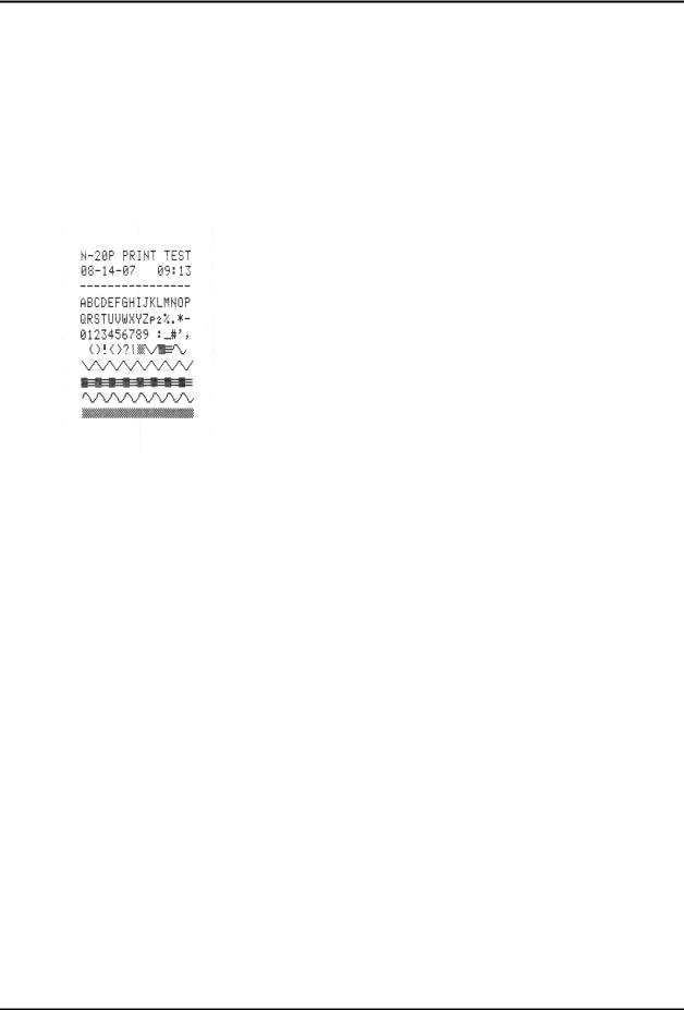
3.Press the printer ON button: "On" appears in the Oxygen Saturation display. A
printer test pattern prints out; the following is an approximate example of the test pattern:
Examine the test pattern to verify that all dots print with a uniform darkness. Overall printout darkness can be adjusted; to adjust printer darkness, see paragraph 4.6.7. If printout darkness is either irregular or dots are missing, contact Mallinckrodt's Technical Services Department or Mallinckrodt's local representative for assistance.
1.Press the printer ADV button. “Ad” appears in the Oxygen Saturation display. Paper advances one line for each button press.
2.Press the printer D/D button: "dd" appears in the Oxygen Saturation display.
3.End SRC-2 printer test.
3.3.5Hardware and Software Tests
Hardware and software tests include the following:
Operation with a Pulse Oximeter Tester
Normal Operation
3.3.5.1Pulse Oximeter Tester
1.Connect the Nellcor SRC-2 pulse oximeter tester to the monitor.
2.Set the switches on the SRC-2 as follows:
Switch |
Setting |
RATE |
38 |
LIGHT |
LOW |
MODULATION |
LOW |
RCAL/MODE |
RCAL 63/LOCAL |
3. Momentarily press the MEASURE button, and verify the following power-up sequence:
3-4

Performance Verification
4.All indicators—OXYGEN SATURATION, PULSE RATE, PULSE SEARCH, LOW BATTERY, and the PULSE BARS—light for a few seconds. Verify that the OXYGEN SATURATION and PULSE RATE displays indicate "888.”
5.The OXYGEN SATURATION display momentarily indicates the monitor 3 digit software version. The other displays are not lit.
6.Software versions may vary depending on the type of monitor and the date of manufacture.
The N-20P will display printer status immediately after software version display. The OXYGEN SATURATION display will indicate “Pr,” and the PULSE RATE display will indicate either “On” or “OFF.”
The OXYGEN SATURATION display momentarily indicates the letters ”tSt” and the monitor sounds a single tone. The other displays are not lit. “tSt” verifies that the monitor recognizes that a tester is connected.
The OXYGEN SATURATION and PULSE RATE displays indicate “0,” the PULSE SEARCH indicator is flashing, and the PULSE BAR will start to register the simulated pulse.
After a few beats a pulse tone will be heard, and the PULSE SEARCH indicator will turn off. The OXYGEN SATURATION display indicates between 79 and 83 and the PULSE RATE display indicates between 37 and 39.
3.3.6.2 Normal Operation
These tests are an overall qualitative check of the system and require connecting a live subject to the monitor:
Connect a DS-100A Sensor to monitor.
Place the DS-100A Sensor on the subject as recommended in the monitor Operator's Manual. Press the Measure button for at least 5 seconds to turn on the monitor.
The monitor should stabilize on the subject's physiological signal in about 10 to 15 seconds. Verify that the saturation value and pulse rate are acceptable.
3-5

Performance Verification
TEST RESULTS
Model: N-20 Serial:_____________________________
Date:___________Customer Name:________________________________
Description |
Pass |
Fail |
|
Performance Tests |
_____ |
____ |
|
Backlight Test |
_____ |
____ |
|
Battery Performance |
_____ |
____ |
|
Testing the Low Battery Indicator |
_____ |
____ |
|
Power-Up Performance |
_____ |
____ |
|
How to Run the Self-Test |
_____ |
____ |
|
Printer Test |
_____ |
____ |
|
Pulse Oximeter Test |
_____ |
____ |
|
Normal Operation |
_____ |
____ |
|
I certify that the monitor listed in this form has successfully passed all of these tests.
Technician:_________________________________________________Date:____________
I certify that the above signed technician has performed the tests listed on this form and the monitor performs satisfactorily.
Support Center Manager:___________________________________________________Date:____________
3-6

4TROUBLESHOOTING
4.1How to Use This Section
4.2Who Should Perform Repairs
4.3Replacement Level Supported
4.4Obtaining Replacement Parts
4.5Troubleshooting Guide
4.6Service Procedures
4.7Error Codes
WARNING: Disassembly of the instrument exposes hazardous voltages. To avoid injury or instrument damage, disassembly or maintenance must be attempted only by qualified service personnel.
4.1How to Use this Section
This section explains how to identify and correct monitor difficulties and provides procedures for common service-related activities, such as battery replacement, clearing paper jams, and adjusting printer darkness.
Use this section in conjunction with Section 3, Performance Verification, and Section 6, Spare Parts. To remove and replace a part you suspect is defective, follow the instructions in Section 5, Disassembly Guide. The functional circuit analysis, located in the Technical Supplement at the end of this manual, offers information on how the device functions, as well as part locator diagrams and detailed schematic diagrams.
4.2Who Should Perform Repairs
Only qualified service personnel should open the device housing, remove and replace components, or make adjustments. If your medical facility does not have qualified service personnel, contact Mallinckrodt Technical Services.
4.3Replacement Level Supported
The replacement level supported for this product is to the printed circuit board (PCB) and major subassembly level. Once you isolate a suspected PCB, replace the PCB with a known good PCB. Check to see that the trouble symptom disappears and the device passes all performance tests. If the trouble symptom persists, swap the replacement PCB and the suspected malfunctioning PCB (the original PCB that was installed when you started troubleshooting) and continue troubleshooting as directed.
4.4Obtaining Replacement Parts
Mallinckrodt Technical Services provides technical assistance information and replacement parts. To obtain replacement parts, contact Mallinckrodt. Refer to parts by the part names and part numbers listed in Section 6, Spare Parts.
4.5Troubleshooting Guide
This section discusses potential symptoms, possible causes, and actions for their resolution. Should this troubleshooting guide fail to address the symptoms evident in a particular N-20/N-20P, please
4-1

Troubleshooting
contact Mallinckrodt's Technical Services Department or a local Mallinckrodt representative for assistance.
If the N-20/N-20P does not perform as expected:
•Check for proper sensor placement.
•Depending on concentration, indocyanine green, methylene blue, and other intravascular dyes may affect the accuracy of a measurement.
•These instruments are calibrated to read oxygen saturation of functional arterial hemoglobin (saturation of hemoglobin functionally capable of transporting oxygen in the arteries), and significant levels of dysfunctional hemoglobins such as carboxyhemoglobin or methemoglobin may affect the accuracy of a measurement.
If the electronics and/or display functions require testing, refer to Section 3, Performance Verification.
Symptom 1: No response to Measure button.
Cause |
Action |
|
|
Battery access door may not be properly latched. |
Check access door and ensure it is properly |
|
latched. |
Batteries may be discharged. |
Exchange them for a new set. |
|
|
Batteries may be incorrectly installed. |
Ensure that batteries are oriented according |
|
to the polarity indicator. |
Batteries may not be making proper electrical contact. |
Inspect contacts for deformity; clean contacts |
|
to remove oxidization. |
Fuse F1 on the auxiliary PCB may be open. |
See paragraph 4.6.5, Fuse Replacement. |
|
|
Dust may have accumulated under Measure button causing |
Clean contact points under Measure button |
loss of electrical contact. |
(see Section 5.3, N-20 Disassembly Guide). |
4-2

Troubleshooting
Symptom 2: Pulse Search indicator appears for more than 5-10 seconds.
Cause |
Action |
|
|
|
|
Sensor may be improperly positioned. |
Ensure the sensor is correctly applied (see |
|
|
sensor directions for use). |
|
Incorrect sensor may be in use. |
See sensor directions for use to ensure that |
|
|
the patient's weight and sensor application is |
|
|
correct. Test the sensor on another person to |
|
|
verify proper operation. |
|
Perfusion may be too low. |
Check patient status. Test the instrument on |
|
|
someone else, or try another type of sensor. |
|
|
The N-20/N-20P will not make a |
|
|
measurement if perfusion is inadequate. |
|
Foreign material on the sensor LEDs or photodetector may be |
Clean the test area and ensure that nothing |
|
affecting performance. |
blocks the sensor site. |
|
Patient motion may be interfering with the instrument's ability |
If possible, ask the patient to remain still. |
|
to find a pulse pattern. |
Verify that the sensor is securely applied and |
|
|
replace it if necessary, move it to a new site, |
|
Environmental motion may be interfering with the |
||
or use a sensor that tolerates patient |
||
instrument's ability to track a pulse |
||
movement, such as an appropriate adhesive |
||
|
||
The sensor may be too tight, there may be excessive |
||
sensor. |
||
illumination (e.g., a surgical or bilirubin lamp or direct |
|
|
sunlight), or the sensor may be placed on an extremity with a |
|
|
blood pressure cuff, arterial catheter, or intravascular line. |
|
|
The DB-9 sensor connector on the N-20/N-20P may be |
Replace the DB-9 connector (Section 4.6.6). |
|
broken. |
|
Symptom 3: Pulse Search indicator appears after successful measurements have been made.
Cause |
Action |
|
|
|
|
Patient perfusion may be too low. |
Check patient status. Test the instrument on |
|
|
someone else, or try another type of sensor. |
|
|
The N-20/N-20P will not make a |
|
|
measurement if perfusion is inadequate. |
|
Patient motion may be interfering with the instrument's ability |
If possible, ask the patient to remain still. |
|
to find a pulse pattern. |
Verify that the sensor is securely applied and |
|
|
replace it if necessary, move it to a new site, |
|
Environmental motion may be interfering with the |
||
or use a sensor that tolerates patient |
||
instrument's ability to track a pulse. |
||
movement, such as an appropriate adhesive |
||
|
||
The sensor may be too tight, there may be excessive |
||
sensor. |
||
illumination (e.g., a surgical or bilirubin lamp or direct |
|
|
sunlight), or the sensor may be placed on an extremity with a |
|
|
blood pressure cuff, arterial catheter, or intravascular line. |
|
|
Symptom 4: Dashes (– – –) appear in the display. |
||
Cause |
Action |
|
|
The sensor is not connected to the instrument. |
Check all sensor connections; try substituting |
|
another sensor. Check all extension cables. If |
|
an extension cable is in use, remove it and |
|
plug the sensor directly into the instrument. |
Symptom 5: Pr Err is displayed during the Power-On Self-Test (N-20P only).
4-3

Troubleshooting
Cause |
Action |
|
|
The printer is not operational, but the N-20P continues to |
Check to see if the paper is jammed. |
obtain patient measurements. |
Examine the print head and ensure that it has |
|
returned to the home position. |
Symptom 6: Err followed by a number appears on the display.
Cause |
Action |
|
|
See Section 4.7 for error codes. |
Record the number that is displayed. |
|
|
Symptom 7: Time or date is incorrect (N-20P only).
Cause |
Action |
|
|
The real-time clock (RTC) battery may be exhausted. |
Replace the RTC battery (see Section 4.6.4). |
|
Reset the time and date (see Section 4.6.3). |
|
|
Symptom 8: Printer fails to operate (N-20P only).
Cause |
Action |
|
|
Fuse F2 on the auxiliary PCB may be open. |
See paragraph 4.6.5 for information about |
|
fuses. |
Symptom 9: Printer paper advances but instrument does not print (N-20P only).
Cause |
Action |
|
|
The thermal paper may be improperly loaded; characters can |
Ensure that the thermal paper is properly |
be printed on only one side of the thermal paper roll. |
loaded; if needed, remove the roll of printer |
|
paper and reload the printer paper. |
Symptom 10: Paper mechanism jams (N-20P only). |
|
Cause |
Action |
|
|
Note: If a printer paper jam is detected during Power-On Self-Test, Pr Err may appear on the display. |
|
|
|
|
Switch off the N-20P. Then check to see if |
|
the print head is at the home position; if so, |
|
attempt to pull the paper out by pulling |
|
gently—do not force it. |
|
If the print head is not at the home position, |
|
and the paper cannot be easily pulled out |
|
from the printer, then the printer may need to |
|
be disassembled to remove the paper jam |
|
(see Sections 5.3, N-20 Disassembly |
|
Procedure, and 4.6.2, Loading/Clearing |
|
Printer Paper). |
4.6Service Procedures
The following service procedures are most likely to be encountered by the service technician. The PCB designation for a component appears in parentheses, for example, (BT1) or (U15).
4-4
Troubleshooting
4.6.1Installing Batteries
1.Remove the battery cover access door by pressing the battery compartment access door latch.
2.Install four alkaline "C" cell batteries. Be sure to observe the polarity indicator sticker.
3.Replace the battery cover access door.
4.6.2Loading/Clearing Printer Paper
The N-20P uses a thermal paper that can show printed characters on one side only. Make sure that the paper roll is correctly installed; always refer to the graphical instruction label found on the paper roll.
1.Press down and outward on the top of the paper compartment door to remove it.
2.Feed the paper into the paper compartment slot; refer to the graphic label for orientation.
3.Press and hold the ADV button until the end of the paper appears at the paper exit slot.
4.Replace the paper compartment door.
If the paper jams either during the loading process or during printing, proceed as follows:
1.Remove both the paper door and the printer-head access cover.
2.Firmly grab and pull the paper roll backward—out and away from the print head—observe the access to the print head to determine whether or not the paper escaped from the jammed position.
3.If paper remains jammed between the print head and printer, press the ADV button; the jammed paper may work its way out. If the paper remains jammed, and the printer drive does not advance the paper, manually advance the drive gear on the side of the printer to free the paper.
4.If these attempts fail to free the jammed paper, remove the printer from the unit to gain full access (see paragraph 5.3, N-20 Disassembly Procedure).
4.6.3Setting Date and Time
The following procedure applies to the N-20P only.
The following code letters and numbers appear in both Oxygen Saturation and Pulse Rate display fields. The symbol "xx" represents information in the Oxygen Saturation display field and "yy" represents information in the Pulse Rate display field.
Begin this procedure by first removing any sensor from the instrument.
1.Turn on the monitor without the sensor connected. Switch on the N-20P and allow the unit to run the Power-On Self-Test.
2.When dashes appear in the Oxygen Saturation and Pulse Rate displays, press the D/D (day/date) button once. At this point, the Oxygen Saturation display field shows "txx", with "t" representing time; "xx" representing hours, and "yy" representing minutes. Note that "xx" (hours) is flashing.
3.Press the ADV (advance) button repeatedly until the correct hour is displayed.
4.Press the D/D button once. Note that "yy" (minutes) is now flashing.
5.Press the ADV button repeatedly until the correct minute is displayed.
6.At this point, the Oxygen Saturation display field shows "dxx", with "d" representing date; "xx" representing the month, and "yy" representing the date. Note that "xx" (month) is flashing.
7.Press the ADV button repeatedly until the correct month is displayed.
8.Press the D/D button once. Note that "yy" (date) is flashing.
9.Press the ADV button repeatedly until the correct date is displayed.
10.Press the D/D button. At this point, the Oxygen Saturation display field shows "Yxx", with "Y" representing "year.” Note that "xx" (year number) is flashing.
11.Press the ADV button repeatedly until the correct year number is displayed.
12.Press the D/D button once. The N-20P turns itself off within 5 seconds.
4-5

Troubleshooting
13.Date and time are now correct. Check by switching on the N-20P with the printer enabled. After the N-20P executes its Power-On Self-Test, the printer prints the spot check mode header with the correct date and time.
4.6.4Replacing the Real-Time Clock (RTC) Battery
The socket for the RTC battery (BT1) is located on the auxiliary PCB at grid location 5D. Typical life of the clock battery is 5 years.
1.Disassemble the N-20 (see Section 5.3, N-20, Disassembly Procedure).
2.Using a thin flathead screwdriver, gently pry the RTC battery from its socket.
3.Insert a new battery into the socket, observing the polarity indication (socket's clip and battery's flat side are positive).
4.Reassemble the unit.
5.Reset the clock (see paragraph 4.6.3, Setting Date and Time).
4.6.5Replacing Fuses
Two fuses (F1 and F2) are located on the auxiliary PCB. Fuse F1 may open to protect the CPU and its associated components from damage if the power supply malfunctions. Fuse F2 may open to protect the printer from damage due to excessive voltage if the printer head jams or has been physically damaged. Refer to the auxiliary PCB schematic for the locations of F1 and F2.
4.6.6Replacing the DB-9 Connector
1.Disassemble the N-20 (see Section 5.2); the connector is on the main PCB at grid location 3A.
2.Using a low-power soldering iron, unsolder the connector from the PCB and remove it. Save all Teflon tubing, ferrite blocks, and insulating materials for the replacement connector.
3.Install ferrite blocks between plastic lead spacer on the connector and the PCB.
4.Insulate connector pin numbers 2, 3, and 5 with Teflon tubing, and insert inside ferrite block.
5.Add insulating material between each end of ferrite block and PCB, and secure with Loctite glue.
6.Solder new connector to PCB and visually check PCB for stray drops of solder before reassembling.
7.Switch on the N-20/N-20P and test the connector with a patient sensor.
4.6.7Adjusting Printer Darkness
Caution: Adjust the printer darkness setting until the lightest legible print is visible.
Setting the print darker than this could reduce the life of the printer-head. Although the N-20P is designed to automatically compensate for conditions that might influence the quality of the printout, the user may want to adjust the print darkness. The normal darkness setting is set at the factory; this setting maximizes both readability and life of the printer-head.
1.Switch on the N-20P in spot check mode. (Depressing the instrument Measure button once starts Spot-check mode.)
2.Simultaneously press and hold the ADV and ON buttons for 2 seconds. If these buttons are not pressed at the same time, two audible beeps will sound and the N-20P either advances the paper or switches off, depending on which button press is first sensed. If the buttons are pressed at the same time, a single audible beep will sound, Pr SEt is displayed, and the printer prints one of the following 6 lines:
PRINTING LIGHTER |
(10% lighter than normal darkness) |
PRINTING LIGHT |
(5% lighter than normal) |
PRINTING NORMAL |
(normal darkness) |
PRINTING DARK |
(5% darker than normal) |
PRINTING DARKER |
(10% darker than normal) |
PRINTING DARKEST |
(15% darker than normal) |
4-6

Troubleshooting
Note: The parenthetic line description is not printed, and button presses are ignored whenever the printer is printing.
1.Press the ADV button to change the darkness setting. The printer prints a line with each button press, and the setting increments from lighter to darkest and then wraps back to lighter.
2.Allow the N-20P to switch off (about 30 seconds). The last print darkness setting is remembered when the N-20P is switched back on. Test this by repeating the procedure and skipping step 3.
4.7Error Codes
If a failure is detected during the Power-On Self-Test or during any performance test, the error message (Err) appears in the Oxygen Saturation display and a 3-digit error code number appears in the Pulse Rate display.
If an error message appears, find its category (the first digit of the error code represents the category) and record the error code number. Match the number to the description in the following table, and contact Mallinckrodt's Technical Services Department or Mallinckrodt's local representative for assistance.
Internal tests are performed in the order of the table listing. The first error condition encountered is the one displayed.
4.7.1Category 1 — Microprocessor Errors
Table 4-1: Microprocessor Error Codes
Errors in the CPU (main PCB). Likely action is replacement of the CPU.
101 |
Error in internal RAM registers test |
|
|
102 |
Error in zero register test |
103 |
Error in register contents clearing test |
|
|
104 |
Error in register contents increment test |
105 |
Error in register contents decrement test |
|
|
106–109 |
Errors in logical operations test |
|
|
110 |
Error in exchange test |
|
|
111 |
Error in timer tests |
|
|
112 |
Error in window select register test |
|
|
113, 114 |
Errors in stack manipulation test |
|
|
115–117 |
Errors in CPU flags test |
|
|
118 |
Error in interrupt pending register test |
|
|
119 |
Error in program counter test |
|
|
120 |
Error in CPU serial port test |
|
|
121 |
Error in pulse width modulation register test |
|
|
122 |
Error in A/D register test |
|
|
123 |
Error in addressing modes test |
|
|
124 |
Error in high speed input register test |
|
|
125 |
Error in content addressable memory test |
|
|
126–129 |
Errors in arithmetic operations test |
|
|
4.7.2Category 2 — RAM Memory Errors
Errors in RAM memory (main PCB). Likely action is replacement of the main PCB.
4-7

Troubleshooting
201–203 |
Errors in external RAM test |
4.7.3Category 3 — PROM Errors
Errors in PROM memory (main PCB). Likely action is replacement of the PROM.
301 Error in PROM test
4.7.4Category 4 — I/O Port Errors
Errors in the CPU's internal I/O port (main PCB). Likely action is replacement of either the CPU or the main PCB.
401–409 |
Errors in I/O port test |
4.7.5Category 5 — Reserved
4.7.6Category 6 — Clock Errors
Failure of the real-time clock (auxiliary PCB), or timing differences between the CPU’s clock and the real-time clock. Likely action is replacement of the main or auxiliary PCB.
601 |
Failure of real-time clock |
602, 603 |
Errors in real-time clock |
4.7.7Category 7 — Watchdog-Timer Errors
Error in the watchdog-timer circuit of the CPU (main PCB). Likely action is replacement of the CPU.
701, 702 |
Errors in watchdog-timer |
4.7.8Category 8 — Printer Errors
Error in the printer (see Section 5.1, Troubleshooting).
If a printer error condition occurs, no error code number will display, rather the display reads Pr Err.
4-8

5DISASSEMBLY GUIDE
5.1Introduction
5.2Required Equipment/Tools
5.3N-20 Disassembly Procedure
5.4N-20P Disassembly Procedure
WARNING: Only qualified service personnel must perform repair and testing. Improper repair and/or adjustment may compromise patient safety or the accuracy of the instrument.
5.1Introduction
The N-20/N-20P can be disassembled down to all major component parts, including:
•PCBs
•battery
•cables
•chassis enclosures
WARNING: Before attempting to open or disassemble the N-20/N-20P, disconnect the power cord.
Caution: Observe ESD (electrostatic discharge) precautions when working within the unit.
Note: Some spare parts have a business reply card attached. When you receive these spare parts, please fill out and return the card.
5.2Required Equipment/Tools
•Screwdriver, Phillips-head, small
•Screwdriver, Phillips-head, medium
•Pliers, long nose
•Screwdriver, small flathead
•Soldering iron, low-power
•Screwdriver, small blade
•Needle-nose pliers
5.2.1N-20 Disassembly Procedure
Whenever repair or disassembly is required, always wear a ground strap connected to active ground. Before any disassembly or service procedure, switch instrument power off.
5-1
Loading...