

Page 1

TECHNICAL MANUAL
Pulse Oximeter Tester
Model SRC-2
To contact Mallinckrodt’s representative: In the United States,
call 1-800-635-5267 or (314)-654-2000; outside of the United States,
call your local Mallinckrodt representative.
© 2000 Mallinckrodt Inc. All rights reserved. 060288A-1000
Page 2

Mallinckrodt Inc.
675 McDonnell Boulevard
P.O. Box 5980
St. Louis, MO 63134 USA
Telephone 314.654.2000
Toll Free 1.800.635.5267
Mallinckrodt
Europe BV
Hambakenwetering 1
5231 DD’s-Hertogenbosch
The Netherlands
Tel +31.73.6485200
Nellcor Puritan Bennett
4280 Hacienda Drive
Pleasanton, CA 94588 USA
Nellcor Puritan Bennett is a wholly owned subsidiary of Mallinckrodt Inc.
Nellcor is a trademark of Mallinckrodt Inc. C-Lock is a trademark of Mallinckrodt Inc.
To obtain information about a warranty, if any, for this product, contact Mallinckrodt
Technical Services or your local Mallinckrodt representative.
Covered by one or more of the following U.S. Patents and foreign equivalents: 4,621,643;
4,700,708; 4,770,179.
Page 3

CONTENTS
Figures
Tables
Introduction ............................................................................. 1
Electromagnetic Interference ............................................. 1
Unpacking and Inspection .................................................. 2
Manual Introduction ............................................................ 2
Tester Description .............................................................. 3
Guide to Operation.................................................................. 5
Front Panel ......................................................................... 5
Switches and Indicators ..................................................... 6
Basic Operation with Oximeter........................................... 7
Test 1 ........................................................................... 7
Test 2 ........................................................................... 7
Test 3 ........................................................................... 8
Test 4 ........................................................................... 8
Test 5 ........................................................................... 8
Test 6 ........................................................................... 10
Circuit Analysis ....................................................................... 11
Introduction......................................................................... 11
Input Rectifier and Power Circuit........................................ 12
Light Amplitude and Modulation Circuits ............................ 12
Oscillator and Pulse Generator .......................................... 13
ECG Trigger Output (not used by N-20 series) .................. 14
Calibration Resistor ............................................................ 14
Routine Maintenance .............................................................. 15
Service................................................................................ 15
Cleaning Instructions .......................................................... 15
Technical Assistance .......................................................... 15
Returning the SRC-2 .......................................................... 16
Environmental Statement ................................................... 16
iii
Page 4

Contents
Troubleshooting...................................................................... 17
Disassembly Guide ................................................................. 19
Testing and Verification ......................................................... 23
Spare Parts .............................................................................. 35
Specifications .......................................................................... 37
Schematic Diagram ................................................................. 41
Introduction......................................................................... 17
Introduction......................................................................... 19
Disassembly Procedure...................................................... 19
Assembly Procedure .......................................................... 21
Introduction......................................................................... 23
Test Equipment Required................................................... 23
Connector Continuity Test .................................................. 24
Calibration Resistor Test .................................................... 26
Power Distribution Tests .................................................... 27
Oscillator Circuit Tests ....................................................... 28
Gain/Modulation Verification .............................................. 29
ECG Trigger Output Tests.................................................. 33
Overview............................................................................. 35
Controls .............................................................................. 37
Input/Output Connectors .................................................... 38
Calibration Resistors .......................................................... 38
Accuracy............................................................................. 38
Signal Output...................................................................... 38
Emissions Compliance ....................................................... 39
Environmental..................................................................... 39
Mechanical ......................................................................... 39
Overview............................................................................. 41
iv
Page 5

FIGURES
1 Front Panel........................................................................ 5
2 Overall Block Diagram ...................................................... 11
3 SRC-2 Exploded View....................................................... 20
4 Ten-Position Header Connector (P2)................................ 24
5 Nine-Position Oximeter D-Connector................................ 24
6 Main PCB Component Location........................................ 41
S-1 Schematic, PCB ................................................................ 43
TABLES
1 Connector Pins.................................................................. 25
Contents
v
Page 6

THIS PAGE INTENTIONALLY LEFT BLANK
Page 7

INTRODUCTION
Electromagnetic Interference
Unpacking and Inspection
Manual Introduction
Tester Description
ELECTROMAGNETIC INTERFERENCE
This device has been tested and found to comply with the limits of
the Electromagnetic Compatibility Directive 89/336/EEC. These
limits are designed to provide reasonable protection against
harmful interference in a typical installation. However, because of
the proliferation of radio-frequency transmitting equipment and
other sources of electrical noise in the health-care and home
environments (for example, cellular phones, mobile two-way
radios, electrical appliances), it is possible that high levels of such
interference due to close proximity or strength of a source, may
result in disruption of performance of this device.
This equipment generates, uses and can radiate radio frequency
energy and, if not installed and used in accordance with the
instructions, may cause harmful interference with other devices in
the vicinity. Disruption or interference may be evidenced by
erratic readings, cessation of operation, or other incorrect
functioning. If this occurs, the site use should be surveyed to
determine the source of this disruption, and actions taken to
eliminate the source.
The user is encouraged to try to correct the interference by one or
more of the following measures:
Turn equipment in the vicinity off and on to isolate the offending
equipment.
Reorient or relocate the other receiving device.
Increase the separation between the interfering equipment and
this equipment.
If assistance is required, contact Mallinckrodt’s Technical
Services Department or your local Mallinckrodt representative.
1
Page 8

Introduction
UNPACKING AND INSPECTION
Upon receipt, inspect the shipping container, if it is damaged,
immediately notify the carrier. The shipping container holds one
SRC-2, one ECG patch cord cable Type L, and one service
manual. Inspect each item, if the SRC-2, the patch cord cable, or
the service manual is missing or damaged, immediately contact
Mallinckrodt’s Technical Services Department or Mallinckrodt’s
local representative.
MANUAL INTRODUCTION
WARNING: Carefully read the operating instructions and all
precautionary information (set in boldface type) before use.
This manual provides service information for the Nellcor pulse
oximeter tester, model SRC-2. The SRC-2 is not intended for use
with Nellcor pulse oximeter models N-10, N-30, or the 4-button
N-100.
Note: This information is intended only for use by qualified
service personnel.
The first three sections describe the SRC-2, give instructions for
using it to test pulse oximeters, and provide a circuit description.
The remaining sections describe troubleshooting, disassembly,
test and calibration verification procedures, and provide a
schematic diagram and a spare parts lists.
2
Page 9

TESTER DESCRIPTION
The SRC-2 tests the light emitting diode (LED) drive circuits and
internal detect circuits of Nellcor pulse oximeters. The SRC-2 is
powered by the oximeter LED drive signals. Switches allow the
selection of RATE, LIGHT, and MODULATION levels, mode of
operation and RCAL. (RCAL is a parameter used to select the
calibration curve.) LEDs provide an indication that drive signals
from the oximeter are active.
Introduction
Note: This device is designed to verify the calculated SpO
2
value at 81% ±2, and not any other values.
Note: Due to the pulse wave shape generated by the SRC-2
tester and Nellcor’s oximetry sampling technique, the
pulse rate tolerance at high pulse rates slightly exceeds the
oximeter’s pulse rate accuracy specification. The
oximeter’s pulse rate specification is based on the clinical
performance with physiological pulses rather than the
square wave pulses generated by the SRC-2 tester.
Note: The SRC-2 is intended to be used to assist verification of
the operation of Nellcor oximeters and is not to be used to
verify calibration of these oximeters. Refer to the
oximeter’s service manual for calibration instructions, if
applicable.
3
Page 10

THIS PAGE INTENTIONALLY LEFT BLANK
Page 11
GUIDE TO OPERATION
Front Panel
Switches and Indicators
Basic Operation with Oximeter
FRONT PANEL
2
1
IR
RED
112
20138
RATE
HIGH 1
LOW
HIGH 2
LIGHT
LOW
HIGHOFF
MODULATION
RCAL/MODE
RCAL 63RCAL 64
LOCALREMOTE
C-LOCK TEST
!
MODELS N-10, N-30, OR 4-BUTTON N-100
MODEL SRC-2
NOT FOR USE WITH NELLCOR
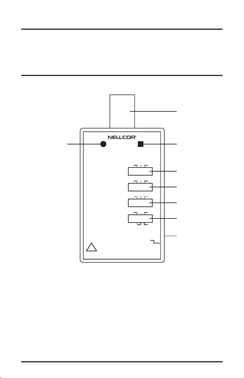
Figure 1: Front Panel
1. IR LED drive input indicator.
2. Standard oximeter connector.
3. RED LED drive input indicator.
4. Pulse RATE selector switch (38, 112, 201)
5. LIGHT output switch (low, high 1, high 2)
6. MODULATION selector switch (off/low/high)
7. RCAL/MODE selector switch
3
4
5
6
7
8
8. C-Lock® TEST input connector
5
Page 12

Guide to Operation
SWITCHES AND INDICATORS
The SRC-2 front panel has four switches and two LED indicators.
• The IR LED drive indicator (1) and the RED LED drive
indicator (3) illuminate when the OXIMETER is switched
ON and the SRC-2 is connected to it. The LEDs indicate that
the oximeter LED drive circuit signals are functional.
• The RATE switch (4) sets internally generated pulse rates: 38
beats/minute (bpm), 112 bpm, and 201 bpm.
• The LIGHT switch (5) has three positions (low, high 1, and
high 2). Low simulates a condition of dark-colored skin or
thick tissue between the sensor LEDs and the photo detector.
The two high settings simulate conditions of light-colored
skin or thin tissue between the sensor LEDs and the photo
detector.
• The MODULATION switch (6) has three positions (off, low,
and high) and controls amplitude of modulation. The high
setting is equivalent to strong pulse signals detected by an
oxygen transducer, and low setting is equivalent to weak
pulse signals.
• The RCAL/MODE switch (7) selects SRC-2 controlled pulse
rates, light level, and modulation when set to LOCAL, while
also testing the RCAL 63 resistor. When set to REMOTE,
local functions are disabled. When set to RCAL 64, this
resistor is selected.
Note: REMOTE mode is reserved for future use. Do not
use this mode with test procedures in this manual.
6
Page 13

BASIC OPERATION WITH OXIMETER
1. Turn the oximeter off.
2. Connect the SRC-2 to the sensor connector.
3. Turn the oximeter on.
Ensure that the SRC-2 IR and RED LED drive indicators are
both lit.
4. Set the RCAL/MODE switch to RCAL 63/Local.
5. Set the LIGHT and MODULATION switches as required by
test procedures 1–4 listed on the following page. Allow the
oximeter a few seconds to obtain a steady reading.
6. Observe and record the OXIMETER SpO
saturation and pulse rate. These readings should be within the
specifications defined in each of the tests listed below.
Test 1
1. Set the LIGHT switch to HIGH 1.
Guide to Operation
readings for
2
Test 2
2. Set the MODULATION switch to HIGH.
3. Set the RATE switch to 112.
4. Verify the following readings on the oximeter:
Saturation (%): 81 ±2
Rate (bpm): 112 ±2% (110 to 114)
1. Set the LIGHT switch to LOW.
2. Set the MODULATION switch to LOW.
3. Set the RATE switch to 201.
4. Verify the following readings on the oximeter:
Saturation (%): 81 ±2
Rate (bpm): 201 ±3% (195 to 207)
7
Page 14

Guide to Operation
Test 3
1. Set the LIGHT switch to HIGH 2.
Note: For the N-100C oximeter, use the high 1 setting.
2. Set the MODULATION switch to LOW.
3. Set the RATE switch to 38.
4. Verify the following readings on the oximeter:
Saturation (%): 81 ±2
Rate (bpm): 38 ±2% (37 to 39)
Test 4
1. Set the LIGHT switch to LOW.
2. Set the MODULATION switch to HIGH.
3. Set the rate switch to 201.
4. Verify the following readings on the oximeter:
Test 5
8
Saturation (%): 81 ±2
Rate (bpm): 201 ±3% (195 to 207)
1. Set the modulation switch to OFF.
2. Set the RCAL switch to RCAL 63.
3. On the oximeter, locate the applicable memory location:
Page 15

Guide to Operation
Oximeter
N-20 Series
N-100C
N-200
N-180/N-185
N-1000/
N-2500
N-6000/
N-6000B
Memory
Location
9
9
3
9
Service
Screen
SpO2
board
Procedure for finding correct
memory location.
Note: The RCAL value cannot be displayed on
N-20 series oximeters.
1. On the oximeter, press the high sat and audio
alarm off buttons simultaneously.
2. Rotate the control knob until “9” (“3” for the
N-180/N-185) appears in the SAT display field.
3. Note the RCAL value displayed in the Rate
display field.
1. From the main menu, press SETUP.
2. Press OFFLINE MENU.
3. Move the curser to ENGINEERING MENU,
then press EXECUTE.
4. Move the cursor to EXAMINE SAT MEMORY,
then press EXECUTE.
5. Rotate the control knob clockwise to reach item
#9.
6. Note the displayed RCAL value.
1. On the monitor, press the FREEZE button.
2. Press unlabeled menu soft keys 2 and 4
simultaneously.
3. Press “Service” soft key.
4. Press “SpO2” soft key.
5. Note displayed “CALIB. INDEX” RCAL value.
N-3000 Service
Menu,
item #30
1. While simultaneously holding down the upper
and lower limit buttons and the print button,
turn the oximeter on.
2. After the tone, release the three buttons.
3. Press the print button again to confirm that you
are in the service mode.
4. Rotate the control knob to reach item #30.
5. Press the upper limit key.
6. Note displayed RCAL value.
9
Page 16

Guide to Operation
4. Verify displayed value to be 63.
5. Change the SRC-2 RCAL switch to RCAL 64.
6. On the monitor, verify that the displayed value changes to 64
within 10 seconds.
Test 6
Note: Test 6 is used only on the N-200, N-1000/N-2500, and
N-6000 series monitors.
1. Use the PC-L cord to connect the SRC-2 C-Lock
connector to the oximeter C-Lock or ECG IN connector.
2. Power up the oximeter.
3. Set the LIGHT switch to LOW.
4. Set the MODULATION switch to LOW.
5. Set the RATE switch to 201.
6. Set the RCAL switch to RCAL 63.
7. Verify the following readings on the oximeter:
®
TEST
10
Saturation (%): 81 ±2
Rate (bpm): 201 ±3% (195 to 207)
8. Ensure that the “C-Lock” or “ECG in Use” indicator lights up
on the oximeter.
Page 17

CIRCUIT ANALYSIS
Introduction
Input Rectifier and Power Circuit
Light Amplitude and Modulation Circuits
Oscillator and Pulse Generator
ECG Trigger Output (not used on N-20 series)
Calibration Resistor
INTRODUCTION
This section discusses SRC-2 operation at the block diagram
level. Refer to Figure 2 and the schematic diagram.
Simulated sensor
output to oximeter
LED drives
from oximeter
Amplifier
Rectifier
and power
circuit
Light switch
Modulation
switch
+Vcc
Remote
Pulse
conditioning
Pulse
rate
generator
38
112
201
Local
ECG
generator
ECG
trigger
63
RCAL
64
Crystal
Figure 2: Overall Block Diagram
This section is divided into the following circuit subsections:
• Input rectifier and power circuit
• Light amplitude and modulation circuits
• Oscillator, divider, and pulse generator
• ECG trigger output.
• Calibration resistor (RCAL)
11
Page 18

Circuit Analysis
INPUT RECTIFIER AND POWER CIRCUIT
Schottky diodes CR4 and CR5 shunt the LED drive signal at J1–5
and J1–6 to ground, and provide a power source of approximately
4.5 V. The full wave bridge rectifier (DS1, DS2, CR2, CR3, and
the parallel load resistors R4 and R5) transforms the LED drive
signal to an offset unipolar signal, which is sensed at the
differential amplifier U4.
The output, measured at U4–14, is 5 mV per mA of input current.
The output of the following amplifier U4–1, measured at (TP4),
has a gain of four. The output waveform at U4–1 corresponds to
the absolute value of the incoming LED drive current, with a
resultant voltage output to current input conversion ratio of 20
mV/mA.
The LED drive signal may be sent directly to the output connector
through S4–3, 2 (REMOTE) to J2–1; or, it may be routed through
the light amplitude and modulation circuitry to create pulses
before being sent to the output connector through S4–1, 2
(LOCAL) to J2–1.
LIGHT AMPLITUDE AND MODULATION CIRCUITS
The signal at U4–1 is routed through S2–6 and R12 to voltage
follower U4–5, 6, 7. When Q1 is off (Q1 gate/TP5 low), both R13
and R14 are out of the circuit and the signal passes straight to the
output at U4–7. This allows the relative light level to be selected
using S2–1.
The HIGH light level signal from U4–7 passes through R8 in
HIGH 2 setting and through the series combination of R8 and R30
in HIGH 1 setting. The signal is routed to S2–3 with a scale factor
of 267 nA/mA or 100 nA/mA of LED drive, respectively.
12
Page 19

The LOW light level signal is created by dividing the HIGH light
level signal by 11 through voltage divider R19 and R20. The
LOW light level signal from U4–8 passes through R7, and is
routed to S2–3 at a scale factor of 7 nA/mA.
The signal at U4–1 is modulated when Q1 is switched on by the
oscillator circuitry (TP5 high) to create a voltage divider.
R14 in conjunction with R12 creates a reduction in signal level
corresponding to the HIGH modulation setting.
R13 in conjunction with R12 creates a reduction in signal level
corresponding to the LOW modulation setting.
The shape of the modulating wave is modified from a square wave
by high pass network C12 and R36.
OSCILLATOR, DIVIDER, AND PULSE GENERATOR
The pulse rate signal used to switch the gate of Q1 is derived from
the oscillator and divider circuits consisting of U1, U2, U3, Y1,
and RATE switch S1.
Circuit Analysis
The oscillator circuit consists of the 32.768 kHz crystal Y1, the
fourteen stage counter U3, and the NAND gate U1. U3 is used to
divide down the high frequency. It does this by combining the
outputs Q13 (4096), Q12 (2048), Q10 (512), Q9 (256) and Q6
(32) in a four-bit word at U1, which resets the counter at the
required frequency.
This frequency is determined by the RATE switch S1 pins 1, 2 &
4. The 32,768 Hz crystal input signal is divided by 4896 to 6.6928
Hz (201), 4384 to 7.4745 Hz (112) and 6432 to 5.0945 Hz (38),
which is provided as the input to the U2 ripple counter.
The U2 ripple counter divides the oscillator signal to achieve the
selected pulse generator output RATE, via S1 pins 5, 7, & 8,
which drives the modulator circuitry.
13
Page 20

Circuit Analysis
With the RATE setting of 201, U2 divides the 6.6928 Hz signal
by 2 to 3.3464 Hz, which equals 200.784 bpm. With the RATE
setting of 112, U2 divides the 7.4745 Hz signal by 4 to 1.8686 Hz,
which equals 112.1175 bpm. And, with the RATE setting of 38,
U2 divides the 5.0945 Hz signal by 8 to 0.6368 Hz, which equals
38.20875 bpm. These signals are selected by the RATE switch S1
and routed from S1–6 to the gate of Q1 for modulating the U4–1
signal output.
The Pulse Generator circuit is disabled when the MODULATION
switch S3 is placed in the OFF position. In the OFF position, U2
is placed in the RESET state when Vcc is applied to pin U2-2 via
S3-6 and S3-8.
ECG TRIGGER OUTPUT
Note: ECG Trigger Outpug is used only on the N-200,
N-1000/N-2500, and N-6000-series monitors.
The ECG trigger output is formed by wave-shaping the rising
edge of the gate drive pulse output from S1–6. This signal is
capacitively coupled through C10 to R23 where it exponentially
decays at a time constant of 25 ms. This 4.2 V peak signal is then
divided by two through R24 and R25 and presented at the base of
Q2.
Q2 is an emitter follower, supplied by an approximate 0.6 V
supply consisting of R28 and forward-biased CR6. This limits the
positive peak of the output signal to approximately 0.5 V once the
saturation voltage of Q2 is subtracted. This signal at output
(TP10) is approximately 25 ms wide.
CALIBRATION RESISTOR (RCAL)
R9 is a 768Ω resistor that notifies the oximeter that an SRC-2 is
attached (RCAL 63), and allows the oximeter diagnostics to be
activated. R31 is a 6.04 kΩ resistor used when RCAL/MODE
switch is set to RCAL 64.
14
Page 21

ROUTINE MAINTENANCE
Service
Cleaning Instructions
Technical Assistance
Returning the SRC-2
Environmental Statement
SERVICE
WARNING: Carefully read the operating instructions and all
precautionary information (set in boldface type) before use.
The SRC-2 requires no routine service other than that which is
mandated by your local institution.
CLEANING INSTRUCTIONS
Caution: Do not immerse the SRC-2 in liquid or use caustic or
abrasive cleaners.
To clean the SRC-2 surfaces, dampen a cloth with a commercial,
nonabrasive cleaner and wipe the surfaces lightly. Do not spray or
pour any liquid directly on the SRC-2. Do not allow any liquid to
penetrate switches, connectors, or openings in the chassis.
TECHNICAL ASSISTANCE
For technical information and assistance or to order parts, contact
Mallinckrodt’s Technical Services Department or Mallinckrodt’s
local representative.
15
Page 22

Routine Maintenance
RETURNING THE SRC-2
If it is necessary to return the SRC-2, call Mallinckrodt’s
Technical Services Department for shipping instructions.
Pack in the original shipping carton. If the carton is not available,
use a suitable box with an appropriate amount of packing material.
ENVIRONMENTAL STATEMENT
Follow local governing ordinances and recycling plans regarding
disposal or recycling of device components.
16
Page 23

TROUBLESHOOTING
Introduction
INTRODUCTION
This section describes troubleshooting for the SRC-2. If questions
arise, contact Mallinckrodt’s Technical Services Department or
your local Mallinckrodt representative.
1. No saturation or pulse rate readings.
• Ensure that the MODE switch is in the LOCAL/RCAL
63 position.
• MODULATION switch is in the OFF position. Select
LOW or HIGH setting.
• Try the SRC-2 on another oximeter.
• Refer to test and calibration procedures.
2. Saturation or pulse rate readings are too high or too low.
• Ensure that the MODE switch is in the LOCAL/RCAL
63 position.
• Try the SRC-2 on another oximeter.
• Refer to the applicable oximeter service manual for
further troubleshooting information.
3. No C-Lock
• Ensure PC-L cable is plugged in at both ends.
• Check cable for continuity.
• Try another oximeter.
17
Page 24

THIS PAGE INTENTIONALLY LEFT BLANK
Page 25

DISASSEMBLY GUIDE
Introduction
Disassembly Procedure
Assembly Procedure
INTRODUCTION
This section describes how to disassemble the SRC-2 for
troubleshooting or testing. An assembly procedure is also
included. Figure 3 shows the SRC-2 exploded view.
DISASSEMBLY PROCEDURE
1. Slide all switches fully toward the center of the top cover.
2. Using a No. 2 Phillips screwdriver, remove the screw from
the back of the case.
3. Hold the SRC-2 together and turn it topside up. Separate the
two halves of the case by pulling gently on the top and the
bottom covers. Set the top cover assembly aside.
4. Remove the printed circuit board assembly from the bottom
cover’s PCB locating pins by pulling gently straight up.
5. Disconnect the cable from the PCB.
6. To replace the oximeter connector cable, remove the cable
assembly from the bottom cover by lifting straight up.
7. To replace the bottom cover, the end plug may be removed
from the bottom cover by pulling upward.
8. To replace the switch caps:
• Remove the top cover.
• Slide the switch cap toward the outer edge of the top
cover.
• Lift out the end of the cap that points toward the center.
19
Page 26

Disassembly Guide
10
1
2
3
4
5
20
9
Figure 3: SRC-2 Exploded View
1. Switch label 6. Bottom cover
2. Switch caps 7. Product Label
3. Top cover 8. Pan head screw
4. Main PCB assembly 9. End plug
5. Oximeter D-connector assembly 10. Ten-position header
connector
6
7
8
Page 27

ASSEMBLY PROCEDURE
1. Refer to Figure 3 for proper orientation of the parts within the
final assembly.
2. Slide the end plug into the bottom cover at the end nearest the
small half-round cutout C-Lock test jack in the cover side
edge.
3. To install the oximeter connector cable assembly, ensure that
the
9-pin D-connector is aligned with the row of five pins at the
top. Align the slot in the bottom cover between the ribs on the
connector and push downward.
4. Loop the cable around the molded screw boss so that the
cable lies in the center of the cover. Plug the 10-position
connector end into J2 on the PCB.
5. Position the PCB such that the LEDs are at the same end as
the
D-connector. Then press the PCB gently down over the three
locating pins.
6. Carefully align and apply the top cover label.
Disassembly Guide
7. With the top cover outer surface facing up, install the four
switch caps in the slots by tipping them into the slots. Slide
the caps fully toward the outside edge of the cover before
pressing them into place. Note that the slot closest to the halfround cutout in the cover edge is left empty.
8. Position the four switches (S1, S2, S3, S4) on the PCB in the
center location. Position S5 in the Right location.
9. Position the switch caps toward the center of the switch slot.
10. Place the top cover assembly over the bottom cover
assembly, ensuring that the switches (S1–S4) on the PCB are
in the center position, and aligned with the switch caps.
11. Press the top and bottom covers together. Turn over the
assembly and replace the screw. Using a No. 2 Phillips
screwdriver, tighten until firm (about 8–9 in-lb torque).
12. Reapply bottom cover label.
21
Page 28

THIS PAGE INTENTIONALLY LEFT BLANK
Page 29

TESTING AND VERIFICATION
Introduction
Test Equipment Required
Connector Continuity Test
RCAL Resistor Test
Power Distribution Tests
Oscillator Circuit Tests
Gain/Modulation Verification
INTRODUCTION
This section outlines procedures for testing SRC-2 operation.
Testing involves disassembling the unit to gain access to test
points on the PCB and pins on J2.
TEST EQUIPMENT REQUIRED
Testing the SRC-2 requires the following commercially available
test equipment.
Equipment Characteristics
Oscilloscope:
Tektronix Model 465,
or equivalent
Frequency Counter:
Hewlett-Packard
Model 5314A,
or equivalent
Digital Multimeter:
FLUKE Model 8840A, or
equivalent
(Note: two meters are
required.)
DC Power Supply:
Topward Model
TPS-4000D, or equivalent.
Variable Resistor:
• Bandwidth: 15 MHz.
• Input impedance: >10 MΩ
• Vertical sensitivity: 10 mV/div.
• Frequency: 1 MHz, minimum.
• Input impedance: > 1 MΩ.
• Minimum sensitivity:
• 100 mV p–p.
• Accuracy: ± 0.5%.
• DC voltage measurement range:
200 mV to 10 V, full scale.
• Resolution: 4 digits.
• DC current measurement range:
200 µA to 1 A, full scale.
• Resistance measurement range 200 Ω
to 20 MΩ, full scale.
• Output: 0 to 5 V, 0 to 100 mA.
• Resistance: 0 to 100 Ω.
23
Page 30

Testing and Verification
CONNECTOR CONTINUITY TEST
Measure continuity from the nine-position oximeter D-connector
to the ten-position header P2 on the SRC-2. (Refer to Table 1.)
Verify resistance at 0.5 ohms maximum, between connector pins.
Refer to the illustrations below for connector and header pin
locations. Note that these views are looking into the cable
connector at each respective end.
Key
2 4
1 3 5 7 9
Figure 4: Ten-Position Header Connector P2
6 8
10
24
12345
6789
Figure 5: Nine-Position Oximeter D-Connector
Note: One version of the SRC-2 has a D–connector with only
seven pins present, as compared to nine pins on the older
version. Determine the connector type and use the
information in the following table to test continuity, as
appropriate, between the oximeter D–connector pins and
the pins on 10–position header connector P2.
Page 31

Table 1: Connector Pins
Nine-Position Oximeter
D-connector Pins
12
26
35
∗
4
51
63
7 9, 10 (inner, outer shield)
8
*
9 No connection
No connection 4 (key)
Header Connector P2 Pins
Testing and Verification
Ten-Position
7
8
∗
These pins are not present in newer connectors. If all nine pins are present and
the sockets or holes for pins 4 and/or 9 are not present in your cable, contact
Mallinckrodt’s Technical Services Department or your local Mallinckrodt
representative for further instructions.
25
Page 32

Testing and Verification
CALIBRATION RESISTOR TEST
1. Orient the Printed Circuit Board Assembly (PCBA) with the
component side up and connectors J1 and J2 on the left hand
side.
2. Set the actuators (contacts) on the switches as follows:
S1 FAR RIGHT (RATE = 201 BPM)
S2 FAR RIGHT (LIGHT = HIGH 2)
S3 FAR RIGHT (MODULATION = HIGH)
S4 FAR RIGHT (LOCAL/ RCAL 63)
S5 RIGHT (CONTACT not used)
3. On the PCBA, connect a digital multimeter between J2,
pins 2 and 3. Verify that the resistance is between 760 Ω
and 776 Ω.
4. Slide the actuator on S4 to the middle position (REMOTE).
Verify that the resistance is between 760 Ω and 776 Ω
5. Slide the actuator on S4 to the far left position (RCAL 64).
Verify the resistance is between 5.98 kΩ and 6.10 kΩ.
26
6. Slide the actuator on S4 back to the far right position
(LOCAL/RCAL 63).
7. On the PCBA, connect the digital multimeter between J1,
pins 2 and 3. Verify that the resistance is between 760 Ω and
776 Ω.
8. On the PCBA, connect the digital multimeter between J1,
pins 7 and 8. Verify that the resistance is between 3.88 kΩ
and 3.92 kΩ.
9. On the PCBA, connect the digital multimeter between TP6
and TP11. Verify that the resistance is between 74.3 kΩ and
75.8 kΩ.
10. Move the actuator on S2 to the middle position (LIGHT =
HIGH).Verify that the resistance is between 197 kΩ and
201 kΩ.
Page 33

11. On the PCBA, connect the digital multimeter between TP3
and TP11.
12. Move the actuator on S2 to the far left position (LIGHT =
LOW) Verify that the resistance is between 198 kΩ and
202 kΩ.
13. On the PCBA, connect the digital multimeter between TP4
and TP11.
14. Move the actuator on S4 to the middle position (REMOTE).
Verify that the resistance is between 198 kΩ and 202 kΩ
15. On the PCBA, connect the digital multimeter between TP7
and TP11.
16. Move the actuator on S4 to the far left position (RCAL 64).
Verify that the resistance is between 198 kΩ and 202 kΩ.
POWER DISTRIBUTION TESTS
1. Orient the Printed Circuit Board Assembly (PCBA) with the
component side up and connectors J1 and J2 on the left hand
side.
Testing and Verification
2. Set the actuators (contacts) on the switches as follows:
S1 FAR RIGHT (RATE = 201 BPM)
S2 FAR RIGHT (LIGHT = HIGH 2)
S3 FAR RIGHT (MODULATION = HIGH)
S4 FAR RIGHT (LOCAL/ RCAL 63)
S5 RIGHT (CONTACT)
3. On the PCBA, connect the negative output from the power
supply to J2, pin 10.
4. Connect the positive output to J2, pin 6.
5. On the power supply, set the output to 4.5 volts.
6. On the PCBA, connect a digital multimeter between TP7 and
TP8. Verify that the voltage is greater than 4.2 volts.
27
Page 34

Testing and Verification
7. On the power supply, disconnect the lead from the positive
output.
8. Connect an ammeter in series between the power supply
positive output and J2, pin 6. Verify that the current is less
than 6 mA.
9. Remove the ammeter from the circuit.
10. On the PCBA, connect the positive output of the power
supply to J2, pin 5.
11. Connect a digital multimeter between TP7 and TP8. Verify
that the voltage is greater than 4.2 volts.
12. Disconnect the lead from the positive output on the power
supply.
13. Connect an ammeter in series between the power supply
positive output and J2 pin 5. Verify that the current is less
than 6 mA.
OSCILLATOR CIRCUIT TESTS
1. Orient the Printed Circuit Board Assembly (PCBA) with the
component side up and connectors J1 and J2 on the left hand
side.
28
2. Set the actuators (contacts) on the switches as follows:
S1 FAR RIGHT (RATE = 201 BPM)
S2 FAR RIGHT (LIGHT = HIGH 2)
S3 FAR RIGHT (MODULATION = HIGH)
S4 FAR RIGHT (LOCAL/ RCAL 63)
S5 RIGHT (CONTACT)
3. On the PCBA, connect the negative output from the power
supply to TP7.
4. Connect the positive output from the power supply to TP1.
5. On the power supply, set the output to 4.5 volts.
Page 35

6. On the PCBA, connect the input lead of a frequency counter
to TP2.
7. Connect the ground (shield) of this lead to TP7. Verify that
the oscillator frequency is between 32,728 and 32,808 Hz.
8. On the PCBA, connect the input lead of an oscilloscope to
TP5.
9. Connect the ground (shield) of this lead to TP7. Verify that
the signal, which approximates a square wave, has an
amplitude greater than 3.5 volts peak-to-peak.
10. Disconnect the frequency counter lead at TP2, and reconnect
it to TP5. Verify that the frequency is between 3.342 and
3.350 Hz.
11. Move the actuator on S1 to the middle position (112 BPM).
Verify that the frequency is between 1.867 and 1.871 Hz.
12. Move the actuator on S1 to the far left position (38 BPM).
Verify that the frequency is between 0.6361 and 0.6377 Hz.
GAIN/MODULATION VERIFICATION
Testing and Verification
1. Orient the Printed Circuit Board Assembly (PCBA) with the
component side up and connectors J1 and J2 on the left hand side.
2. Set the actuators on the switches as follows:
S1 FAR RIGHT (RATE = 201 BPM)
S2 FAR RIGHT (LIGHT = HIGH 2)
S3 FAR RIGHT (MODULATION = HIGH)
S4 FAR RIGHT (LOCAL/ RCAL 63)
S5 RIGHT (CONTACT)
29
Page 36

Testing and Verification
3. On the power supply, connect two test leads to the positive
output.
4. On the PCBA, connect one of the positive power supply leads
to TP1 and the other to TP9.
5. Connect the negative power supply output to TP7.
6. On the power supply, set the output voltage to 4.5 volts.
7. On the PCBA, verify that both LEDs are not illuminated.
8. Using the digital multimeter:
• connect the positive lead to TP5 on the PCBA, and
• connect the negative lead to TP7.
Verify that the voltage is 0 ± 0.25 volts.
9. On the PCBA, connect the positive lead of the multimeter to
J2, pin 1. Verify that the voltage is 0 ± 0.10 volts.
10. Connect the positive lead of the multimeter to TP4. Verify
that the voltage is less than 0.2 volts.
11. Disconnect the positive power supply lead from TP1. Only
TP9 should now have a positive power supply lead attached.
30
12. Connect a variable resistor and an ammeter in series between
TP1 and TP7.
13. Adjust the resistance to obtain a reading of 50 mA. Verify
that DS1 (left side LED) is illuminated.
14. Connect the positive lead of the multimeter to TP1 on the
PCBA. Verify that the voltage is greater than 2.0 volts.
15. Connect the positive lead of the multimeter to TP4 on the
PCBA. Verify that the voltage is between 0.94 and 1.10 volts.
16. Connect the positive lead of the multimeter to TP6 on the
PCBA. Verify that this voltage is the same voltage as TP4 ±
0.01 volts.
Page 37

Testing and Verification
17. Connect the positive lead of the multimeter to TP3 on the
PCBA. This voltage should equal 0.09 times the voltage at
TP6 ± 0.01 volts.
18. Disconnect the ammeter and variable resistor from TP1.
19. Disconnect the power supply lead from TP9 and connect it to
TP1.
20. Connect the ammeter and variable resistor in series between
TP9 and TP7.
21. Adjust the resistance to obtain a current of 50 mA. Verify
that DS2 (right side LED) is illuminated.
22. Connect the positive lead of the multimeter to TP9 on the
PCBA. Verify that the voltage is greater than 2.0 volts.
23. Connect the positive lead of the multimeter to TP4 on the
PCBA. Verify that the voltage is between 0.94 and 1.10 volts.
Record this measurement. This is the base voltage used to
calculate modulation.
24. Orient the printed circuit board assembly (PCBA) with the
component side up and connectors J1 and J2 on the left- hand
side.
25. Set the actuators on the switches as follows:
S1 FAR RIGHT (RATE = 201 BPM)
S2 FAR RIGHT (LIGHT = HIGH 2)
S3 FAR RIGHT (MODULATION = HIGH)
S4 FAR RIGHT (LOCAL/ RCAL 63)
S5 RIGHT (CONTACT)
26. Connect the oscilloscope input to TP6 on the PCBA.
27. Connect the oscilloscope ground to TP7 on the PCBA.
31
Page 38

Testing and Verification
28. Set the oscilloscope as follows:
• Vertical Gain = 20mV/div.
• AC coupled
• Bandwidth Limit = ON
• Horizontal Sweep = 20 mS/div.
29. Measure the peak of the positive pulse. Record the
measurement.
30. Calculate the % modulation from the formula:
%Modulation =
Voltage at TP6 (recorded in step 29)
X 100%
Voltage at TP4 (recorded in step 23)
Verify that the modulation is between 9% and 11%.
31. Move the actuator on S3 to the middle position
(MODULATION = LOW).
32. Change the Vertical Gain on the oscilloscope to 5mV/div.
33. Measure the peak of the positive pulse and record the
measurement.
34. Verify that the peak negative voltage is, at least, 9mV.
35. Calculate the % modulation from the formula:
%Modulation =
Voltage at TP6 (recorded in step 33)
X 100%
Voltage at TP4 (recorded in step 23)
Verify that the modulation is between 0.8% and 1.2%
32
Page 39

ECG TRIGGER OUTPUT TESTS
1. Orient the Printed Circuit Board Assembly (PCBA) with the
component side up and connectors J1 and J2 on the left hand side.
2. Set the actuators on the switches as follows:
S1 FAR RIGHT (RATE = 201 BPM)
S2 FAR RIGHT (LIGHT = HIGH 2)
S3 FAR RIGHT (MODULATION = HIGH)
S4 FAR RIGHT (LOCAL/ RCAL 63)
S5 RIGHT (CONTACT)
3. On the PCBA, connect the negative output from the power
supply to TP7.
7. Connect the positive output of the power supply to TP1.
8. On the power supply, set the output to 4.5 volts.
9. Connect the oscilloscope input to TP10 on the PCBA.
Testing and Verification
10. Set the oscilloscope as follows:
• Vertical Gain = 0.1V/div.
• DC coupled
• Bandwidth Limit – ON
• Horizontal Sweep = 20 mS/div.
8. Verify that the pulse is positive with a peak amplitude
between 0.3 to 0.7 Volts.
9. Verify that the pulse decays to 0 volts between positive
peaks.
11. Verify that at 50% of the peak voltage, the pulse at TP10 is
between 20 to 50 mS wide.
33
Page 40

THIS PAGE INTENTIONALLY LEFT BLANK
Page 41

SPARE PARTS
Overview
OVERVIEW
This section contains a list of spare parts for the SRC-2. Refer to
the SRC-2 exploded view shown in Figure 3.
Key
Number Description Part No.
1 Switch label 040868
2 Switch caps 028997
3 Top cover 024381
4 Main PCB assembly 029318
5 Oximeter D-connector assembly 044207
6 Bottom Cover 024380
7 Product Label Not Available
8 Pan head screw, 6-32 x 7/8 802088
9 End plug 024382
10 Cable/10-Position Header Connector 044207
Accessory ECG patch cord, Type L PC-L
35
Page 42

THIS PAGE INTENTIONALLY LEFT BLANK
Page 43

SPECIFICATIONS
Controls
Input/Output Connectors
Calibration Resistor
Accuracy
Signal Output
Environmental
Mechanical
CONTROLS
RATE Switch
Three positions:
38, 112, 201 beats per minute
LIGHT Switch
Three positions:
Detected LED light level simulation
Low, High 1, and High 2
MODULATION Switch
Three positions:
Output signal modulation
Off, Low, and High
RCAL/MODE Switch
Three positions:
Local for internally generated rate, signal level, modulation, and
RCAL 63
Remote for testing the SRC-2
RCAL: 64
37
Page 44

Specifications
INPUT/OUTPUT CONNECTORS
Oximeter Input/Output
Nine-pin D-connector
CALIBRATION RESISTORS
768 Ω (RCAL 63)
6.04 kΩ (RCAL 64)
ACCURACY
Rate
38 ±2% (37 to 39)
112 ±2% (110 to 114)
201 ±3% (195 to 207)
SIGNAL OUTPUT
High 2 Light Switch Setting
~267 nA/mA of input current from oximeter
High 1 Light Switch Setting
~100 nA/mA of input current from oximeter
Low Light Switch Setting
~9 nA/mA of input current from oximeter
Modulation Switch Setting
10% in high position
1% in low position
ECG Trigger Output
0.5 V peak; at least 20 ms wide at 50% amplitude; less than 50 ms
wide after pulse rising edge
38
Page 45

EMISSIONS COMPLIANCE
Emissions Classification: CISPR II, Group 1, Class B
ENVIRONMENTAL
Temperature
32 to 104°F (0 to 40°C)
Humidity
Non-condensing
Elevation
0 to 20,000 ft. (0 to 6,100 m)
MECHANICAL
Size
5.0 in. (130 mm) long
2.6 in. (66 mm) wide
1.4 in. (36 mm) deep
Specifications
Weight
4.3 oz (123 g)
39
Page 46

THIS PAGE INTENTIONALLY LEFT BLANK
Page 47

SCHEMATIC DIAGRAM
Overview
OVERVIEW
This section contains the SRC-2 component location drawing
(Figure 6) and the SRC-2 schematic diagram (Figure S-1).
Figure 6: Main PCB Component Location
41
Page 48

 Loading...