

Page 1

SERVICE MANUAL
Nellcor Symphony
®
N-3200 Display/Printer
To contact Nellcor Puritan Bennett’s representative: In the United States, call 1-800-NELLCOR or 510 463-4000;
outside the United States, call your local Nellcor Puritan Bennett representative.
Caution: Federal law (U.S.) restricts this device to sale by or on the order of a physician.
© 1996 Nellcor Puritan Bennett Incorporated. All rights reserved. 035073A-1096
0123
Page 2

Corporate Headquarters
Regional/Local Offices
Nellcor Puritan Bennett Inc.
4280 Hacienda Drive
Pleasanton, California 94588 U.S.A.
Tel. 510 463-4000 or
1-800-NELLCOR
U.S. Service Repair Center
Nellcor Puritan Bennett Inc.
2391 Fenton Street
Chula Vista, California 91914
U.S.A.
Tel. 619 482-5000
European Office
Nellcor Puritan Bennett Europe BV
Hambakenwetering 1
5231 DD ’s-Hertogenbosch
The Netherlands
Tel. +31.73.6485200
Asia/Pacific Office
Nellcor Puritan Bennett HK Ltd.
Room 1602 Evergo House
38 Gloucester Road
Wanchai
Hong Kong
Tel. +852.2529.0363
Nellcor Puritan Bennett UK Ltd.
10 Talisman Business Centre
London Road
Bicester, Oxfordshire OX6 0JX
United Kingdom
Tel. +44.1869.322700
Nellcor Puritan Bennett Belgium
NV/SA
Interleuvenlaan 62/8, Zone 2
B-3001 Heverlee
Belgium
Tel. +32.16.400467
Nellcor Puritan Bennett France
91975 Courtabeouf Cedex
France
Tel. +33.01.69.82.14.00
Nellcor Puritan Bennett Germany
GmbH
Black-&-Decker-Strasse 28
65510 Idstein
Germany
Tel. +49.6126.5930
Nellcor Puritan Bennett Italia Srl
Via dei Tulipani, 3
20090 Pieve Emanuele (MI)
Italy
Tel. +39.2.90786404
To obtain information about a warranty, if any, for this product, contact Nellcor Puritan
Bennett Technical Services or your local Nellcor Puritan Bennett representative.
The following are trademarks of Nellcor Puritan Bennett Inc.: Nellcor Symphony and the
Nellcor Puritan Bennett knob configuration.
Page 3

TABLE OF CONTENTS
List of Figures
List of Tables
Section 1: Introduction
1.1 Manual Overview........................................................................... 1-1
1.2 N-3200 Display/Printer Description ............................................... 1-1
1.3 Related Documents....................................................................... 1-4
Section 2: Routine Maintenance
2.1 Cleaning ........................................................................................ 2-1
2.2 Periodic Safety and Functional Checks......................................... 2-1
2.3 Batteries ........................................................................................ 2-1
Section 3: Performance Verification
3.1 Introduction.................................................................................... 3-1
3.2 Equipment Needed........................................................................ 3-1
3.3 Performance Tests ........................................................................ 3-1
3.3.1 Battery Performance ........................................................ 3-1
3.3.2 Battery Charge................................................................. 3-2
3.3.3 Power-up Performance .................................................... 3-2
3.3.4 Hardware and Software Performance (Service Mode) .... 3-4
3.3.4.1 Button and Knob Tests .................................................... 3-5
3.3.4.2 Display Tests.................................................................... 3-6
3.3.4.3 Printer Tests..................................................................... 3-8
3.3.4.4 Audio Tests ...................................................................... 3-9
3.3.4.5 Stack Performance, N-3000............................................. 3-10
3.3.4.6 Stack Performance, N-3100............................................. 3-12
3.4 Safety Tests .................................................................................. 3-13
3.4.1 Ground Integrity Test ....................................................... 3-13
3.4.2 Electrical Leakage Test.................................................... 3-14
Section 4: Configuration Mode
4.1 Introduction.................................................................................... 4-1
4.2 Entering the Configuration Mode................................................... 4-1
4.3 N-3200 Information........................................................................ 4-2
4.3.1 Configuration Information, N-3200................................... 4-2
4.3.2 Error Log, N-3200 ............................................................ 4-5
4.3.3 Operation Information, N-3200......................................... 4-6
4.3.4 Power Status Information, N-3200................................... 4-6
4.3.5 Printing N-3200 Configuration Mode Information............. 4-7
4.3.6 Reset to Factory Defaults, N-3200................................... 4-7
4.3.7 Real-time Clock Information, N-3200............................... 4-7
4.4 N-3000 Information........................................................................ 4-8
4.4.1 Configuration Information, N-3000................................... 4-8
4.4.1.1 UIF Configuration Information, N-3000 ............................ 4-9
4.4.1.2 SpO2 Configuration Information, N-3000 ......................... 4-10
4.4.1.3 ECG Configuration Information, N-3000.......................... 4-10
4.4.1.4 Resp Configuration Information, N-3000 ......................... 4-11
4.4.2 Error Log, N-3000 ............................................................ 4-11
4.4.3 Operation Information, N-3000......................................... 4-12
4.4.4 Power Status Information, N-3000................................... 4-13
4.5 N-3100 Information........................................................................ 4-13
4.5.1 Configuration Information, N-3100................................... 4-13
4.5.1.1 UIF Configuration Information, N-3100 ............................ 4-14
4.5.1.2 NIBP Configuration Information, N-3100 ......................... 4-14
................................................................................ 1-1
................................................................. 2-1
........................................................... 3-1
................................................................... 4-1
iii
Page 4

Table of Contents
4.5.2 Error Log, N-3100 ............................................................ 4-15
4.5.3 Operation Information, N-3100......................................... 4-15
4.5.4 Power Status Information, N-3100................................... 4-16
4.6 Accessing Configuration Mode from Service Mode....................... 4-16
Section 5: Troubleshooting
5.1 Introduction.................................................................................... 5-1
5.2 How to Use this Section ................................................................ 5-1
5.3 Who Should Perform Repairs........................................................ 5-1
5.4 Replacement Level Supported...................................................... 5-1
5.5 Obtaining Replacement Parts ....................................................... 5-1
5.6 Troubleshooting Guide.................................................................. 5-1
5.6.1 Power............................................................................... 5-3
5.6.2 Error Codes...................................................................... 5-3
5.6.3 Buttons ............................................................................. 5-4
5.6.4 Display/Audible ................................................................ 5-5
5.6.5 Operational Performance................................................. 5-6
5.6.6 Stacked Operation ........................................................... 5-8
Section 6: Disassembly Guide
6.1 Introduction.................................................................................... 6-1
6.2 Fuse Replacement ........................................................................ 6-1
6.3 Disassembly .................................................................................. 6-3
6.3.1 Removing the Display PCB.............................................. 6-6
6.3.2 Removing the Power-On Button PCB.............................. 6-7
6.3.3 Removing the Printer Button PCB.................................... 6-8
6.3.4 Removing the Main Button PCB ...................................... 6-9
6.3.5 Replacing the Lead-Acid Battery...................................... 6-9
6.3.6 Removing the UIF PCB.................................................... 6-11
6.3.7 Replacing the Lithium Battery .......................................... 6-12
6.3.8 Replacing the Printer........................................................ 6-12
6.4 Reassembly................................................................................... 6-15
6.5 Mounting Directions....................................................................... 6-15
Section 7: Spare Parts
7.1 Introduction.................................................................................... 7-1
Section 8: Packing for Shipment
8.1 General Instructions ...................................................................... 8-1
8.2 Repacking in Original Carton ........................................................ 8-1
8.3 Repacking in a Different Carton .................................................... 8-2
Section 9: Specifications
9.1 General.......................................................................................... 9-1
9.2 Electrical........................................................................................ 9-1
9.3 Physical Characteristics ................................................................ 9-1
9.4 Environmental ............................................................................... 9-1
9.5 Factory Default Settings ................................................................ 9-2
Appendix
....................................................................................................... A-1
A1 User-Correctable Error Messages................................................. A-1
A2 Failure Error Codes....................................................................... A-1
A3 Internally Corrected Error Codes................................................... A-2
Technical Supplement
S1 Introduction.................................................................................... S-1
S2 Overview ....................................................................................... S-1
S3 Stackbus Interface......................................................................... S-1
S4 Circuit Analysis.............................................................................. S-2
S4.1 Functional Overview ........................................................ S-2
S4.1.1 Processor......................................................................... S-3
S4.2 Detailed Circuit Analysis .................................................. S-3
......................................................................... 5-1
.................................................................... 6-1
................................................................................. 7-1
................................................................ 8-1
............................................................................. 9-1
................................................................................. S-1
iv
Page 5

LIST OF FIGURES
Table of Contents
S4.2.1 Power Supply and Battery Assemblies ............................ S-3
S4.2.2 UIF Printed Circuit Board................................................. S-4
S4.2.3 Display Assembly............................................................. S-8
S4.2.4 Buttons, Knob, and Indicators.......................................... S-9
S4.2.5 Printer Assembly.............................................................. S-10
S4.2.6 Docking Connector Printed Circuit Board ........................ S-10
S5 Schematic Diagrams .................................................................... S-10
1-1 N-3200 Front Panel (International) .................................................... 1-2
1-2 N-3200 Front Panel (North American)............................................... 1-2
1-3 N-3200 Rear Panel (International)..................................................... 1-3
1-4 N-3200 Rear Panel (North American)................................................ 1-3
1-5 N-3200 Left Side Panel...................................................................... 1-4
3-1 Introduction Screen............................................................................ 3-2
3-2 Service Mode Main Menu Screen...................................................... 3-4
3-3 Button Knob Test Screen................................................................... 3-5
3-4 Pixel Test Display .............................................................................. 3-7
3-5 Waveform Test Display...................................................................... 3-7
3-6 Text Test Display............................................................................... 3-8
3-7 Waveform/Text Test Printout............................................................. 3-8
3-8 Waveform Test Printout..................................................................... 3-9
3-9 Text Test Printout .............................................................................. 3-9
3-10 Pleth Waveform ................................................................................. 3-11
3-11 NIBP Display...................................................................................... 3-13
4-1 Configuration Mode Main Menu......................................................... 4-1
4-2 Configuration Setting Display - Page 1.............................................. 4-2
4-3 Configuration Setting Display - Page 2.............................................. 4-3
4-4 Error Log Display - Page 1 ................................................................ 4-5
4-5 Error Log Display - Page 2 ................................................................ 4-5
4-6 N-3200 Operation Info Display........................................................... 4-6
4-7 N-3200 Power Status Display............................................................ 4-6
4-8 N-3200 Configuration Mode Printout................................................. 4-7
4-9 N-3200 RTC Display.......................................................................... 4-8
4-10 N-3000 UIF Configuration Setting Display......................................... 4-9
4-11 N-3000 SpO2 Configuration Setting Display - Page 1 ....................... 4-10
4-12 N-3000 SpO2 Configuration Setting Display - Page 2 ....................... 4-10
4-13 N-3000 ECG Configuration Setting Display....................................... 4-11
4-14 N-3000 Resp Configuration Setting Display ...................................... 4-11
4-15 N-3000 Error Log Display - Page 1.................................................... 4-12
4-16 N-3000 Error Log Display - Page 2.................................................... 4-12
4-17 N-3000 Operation Info Display........................................................... 4-12
4-18 N-3000 Power Status Display............................................................ 4-13
4-19 N-3100 UIF Configuration Setting Display......................................... 4-14
4-20 N-3100 NIBP Configuration Setting Display - Page 1........................ 4-14
4-21 N-3100 NIBP Configuration Setting Display - Page 2........................ 4-15
4-22 N-3100 NIBP Configuration Setting Display - Page 3........................ 4-15
4-23 N-3100 Operation Info Display........................................................... 4-15
4-24 N-3100 Power Status Display............................................................ 4-16
6-1 Removing the Fuse Cover................................................................. 6-2
6-2 Removing the Fuse Holder ................................................................ 6-2
6-3 Fuse Replacement............................................................................. 6-3
6-4 Removing Bottom Chassis Screws.................................................... 6-4
6-5 Removing Top Cover......................................................................... 6-5
v
Page 6

Table of Contents
LIST OF TABLES
6-6 Disconnecting Cables from UIF Board .............................................. 6-5
6-7 Removing Display Panel.................................................................... 6-6
6-8 Removing Display PCB ..................................................................... 6-7
6-9 Reattaching Display Cable ................................................................ 6-7
6-10 Removing Power-On Button PCB...................................................... 6-8
6-11 Removing Printer Button PCB ........................................................... 6-8
6-12 Removing Main Button PCB.............................................................. 6-9
6-13 Removing Power Supply.................................................................... 6-10
6-14 Removing Lead-Acid Battery............................................................. 6-10
6-15 Removing UIF PCB ........................................................................... 6-11
6-16 Removing Lithium Battery.................................................................. 6-12
6-17 Removing Printer............................................................................... 6-13
6-18 Disconnecting Printer......................................................................... 6-13
6-19 Printer Jumper Connections .............................................................. 6-14
6-20 Mounting to the GCX Poly-Mount...................................................... 6-15
7-1 N-3200 Expanded View..................................................................... 7-2
8-1 Repacking the N-3200....................................................................... 8-1
S4-1 N-3200 Functional Block Diagram..................................................... S-3
S4-2 Internal/External Bus Connections .................................................... S-4
S4-3 Display Assembly Block Diagram...................................................... S-8
4-1 N-3200 Configuration Settings........................................................... 4-3
4-2 N-3000 Configuration Codes ............................................................. 4-13
5-1 Problem Categories........................................................................... 5-2
5-2 Power Problems................................................................................. 5-3
5-3 N-3200 Failure Error Codes............................................................... 5-4
5-4 Button Problems ................................................................................ 5-5
5-5 Display/Audible Problems.................................................................. 5-5
5-6 Operational Performance Problems .................................................. 5-6
5-7 Stack Problems.................................................................................. 5-8
6-1 Printer Jumper Connections .............................................................. 6-14
A-1 N-3200 User-Correctable Error Messages ........................................ A-1
A-2 N-3200 Failure Error Codes............................................................... A-1
A-3 N-3200 Internally Corrected Error Codes .......................................... A-2
vi
Page 7

SECTION 1: INTRODUCTION
1.1 Manual Overview
1.2 N-3200 Display/Printer Description
1.3 Related Documents
1.1 MANUAL OVERVIEW
This manual contains information for servicing the Nellcor Symphony N-3200
display/printer. Only qualified service personnel should service this product.
Before servicing the N-3200, read the operator’s manual carefully for a thorough
understanding of operation.
1.2 N-3200 DISPLAY/PRINTER DESCRIPTION
The Nellcor Symphony N-3200 display/printer prints and graphically displays
data collected by other Nellcor Symphony monitors. The N-3200 is intended for
use with adult, pediatric, or neonatal patients in all hospital areas and
hospital-type facilities.
The N-3200 is not intended to operate independently. It displays waveforms,
trends, and other data associated with given parameters monitored by a Nellcor
Symphony N-3000 patient monitor and/or a Nellcor Symphony N-3100 blood
pressure monitor.
The physical and operational characteristics of the N-3200 are described in the
operator’s manual and Section 9, Specifications, of this manual.
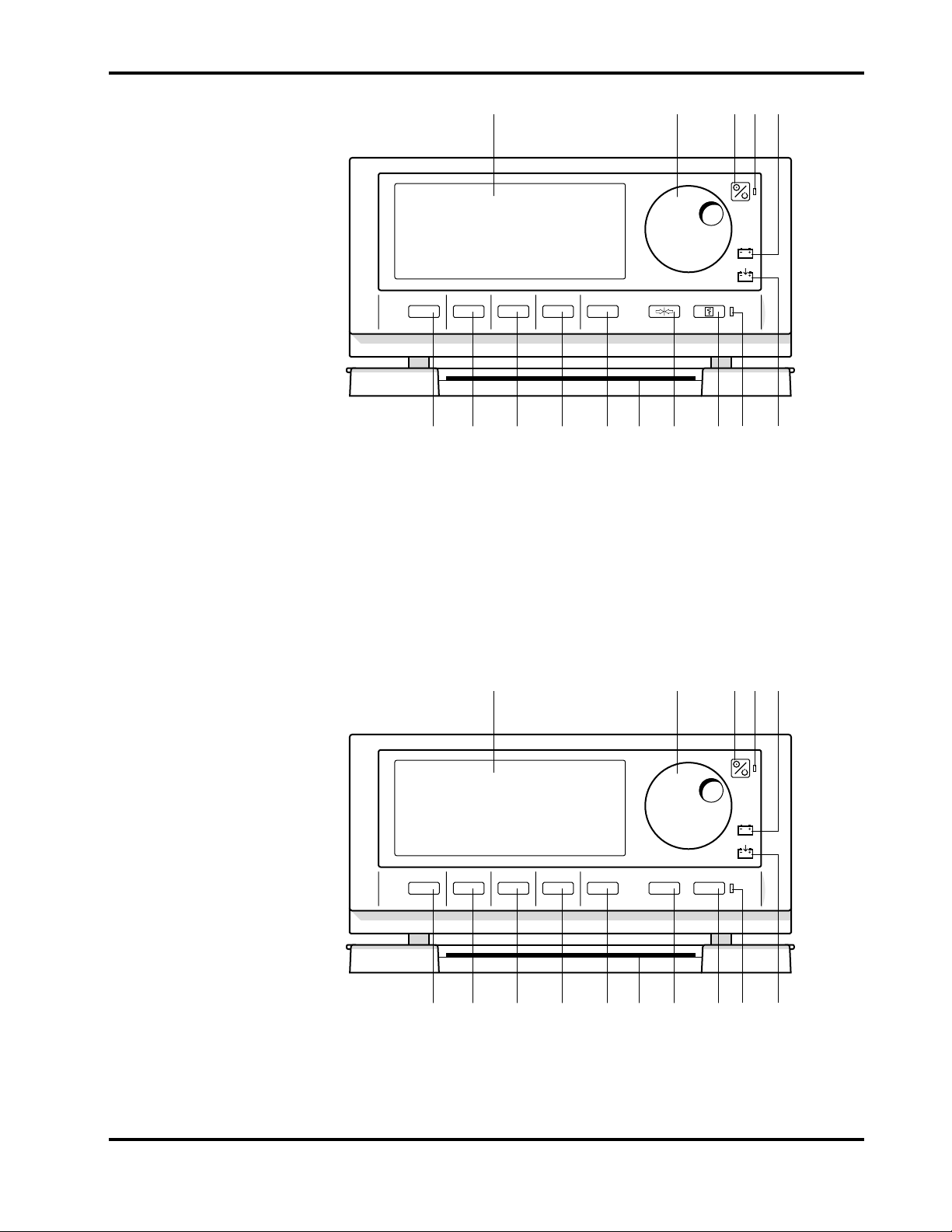
Figures 1-1 and 1-2 depict the International and North American front panels of
the N-3200 and names of its displays and controls.
Note: All graphics in this manual relevant to the N-3200 are depicted in the
International symbol format. Refer to your operator’s manual and
Figures 1-1 and 1-2 of this manual for applicable translations.
1-1
Page 8
Section 1: Introduction
1 2 3 54
710121315 14 11 9 8 6
Figure 1-1: N-3200 Front Panel (International)
1 Display area 9 FREEZE button
2 Control knob 10 Quick Reference Cards
3 ON/STANDBY button 11 Softkey #5
4 POWER ON indicator 12 Softkey #4
5 BATTERY IN USE/BATTERY LOW indicator 13 Softkey #3
6 BATTERY CHARGING indicator 14 Softkey #2
7 STACKED indicator 15 Softkey #1
8 PRINT button
1 2 3 54
FREEZE
PRINT
1-2
710121315 14 11 9 8 6
Figure 1-2: N-3200 Front Panel (North American)
Page 9
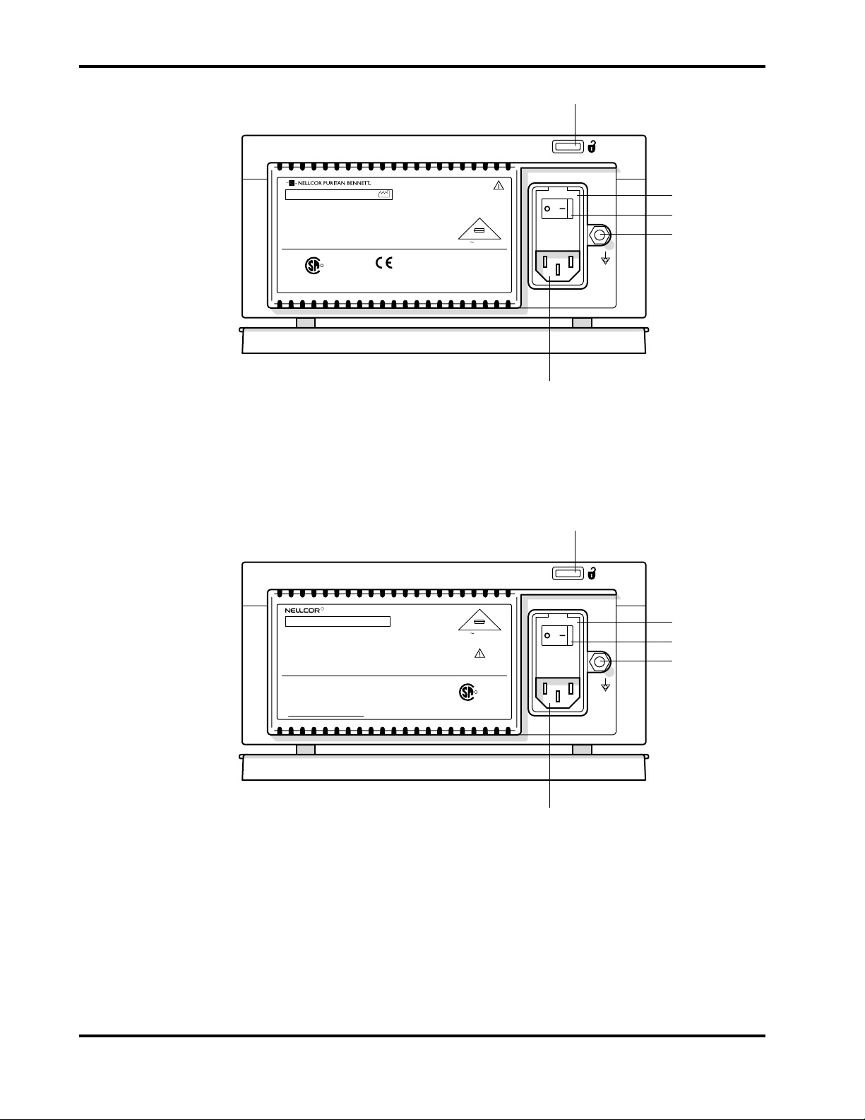
Docking release button
Section 1: Introduction
S/N
NELLCOR PURITAN BENNETT INC., PLEASANTON, CA 94 588 MADE IN U.S.A.
NELLCOR PURITAN BENNETT EUROPE BV, s-HERTOGENBOSCH, THE NETHERLANDS
R
LR 55492
UL 2601-1 NRTL/C CSA 601.1
N-3200-I10
100-240V 50/6 0 Hz 1.7A
0123
Figure 1-3: N-3200 Rear Panel (International)
2X
T 2A 250V
Fuse cover
AC power switch
Ground terminal
034553A-1295
AC receptacle
Docking release button
R
N-3200-N10
S/N
NELLCOR INCORPORATED PLEASANTON, CA 94 588 MADE IN USA
DANGER: RISK OF EXPLOSION IF USED IN
THE PRESENCE OF FLAMMABLE ANESTHETICS
DANGE: RISQUE D'EXPLOSION. NE PAS EMPLOYER
EN PRESENCE D'ANESTHESIQUES INFLAMMABLES.
DO NOT CONNECT TO AN ELECTRICAL
OUTLET CONTROLLED BY A WALL SWITCH.
NE PAS BRANCHER SUR UNE PRISE
ELECTRIQUE COMMANDEE PAR UN
INTERRUPTEUR.
Figure 1-4: N-3200 Rear Panel (North American)
2X
T 2A 250V
100-240V 50/6 0 Hz 1.7A
R
LR 55492
UL 2601-1 NRTL/C CSA 601.1
033840A-0895
Fuse cover
AC power switch
Ground terminal
AC receptacle
1-3
Page 10
Section 1: Introduction
1 2 43
5 6
8
7
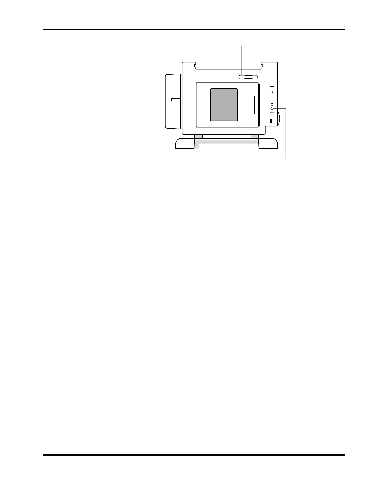
Figure 1-5: N-3200 Left Side Panel
1 Printer Door 5 Paper Exit
2 Printer Window 6 PAPER FEED Button
3 Paper Release Actuator 7 PRINTER ON/OFF Button
4 Door Release Latch 8 PRINTER ON Indicator
1.3 RELATED DOCUMENTS
To perform test and troubleshooting procedures and to understand the principles
of operation and circuit analysis sections of this manual, you must know how to
operate the N-3200. Refer to the N-3200 operator’s manual. To understand how
the N-3200 operates with the N-3000 or N-3100, refer to the appropriate
operator’s manual.
1-4
Page 11

SECTION 2: ROUTINE MAINTENANCE
2.1 Cleaning
2.2 Periodic Safety and Functional Checks
2.3 Batteries
2.1 CLEANING
Caution: Do not immerse the N-3200 in liquid or clean with caustic or
abrasive cleaners, chlorofluorocarbons, or petroleum solvents. Do not
spray or pour any liquid on the N-3200.
To clean the N-3200, dampen a cloth with a commercial, nonabrasive cleaner
and wipe the exterior surfaces lightly. Do not allow any liquids to come in
contact with the power connector, fuse holder, or switches. Do not allow any
liquids to penetrate connectors or openings in the instrument cover.
2.2 PERIODIC SAFETY AND FUNCTIONAL CHECKS
The following checks should be performed at least every 2 years by a qualified
service technician. They should also be performed whenever the N-3200 is
repaired, has had its covers removed, or has been returned from outside your
institution’s control.
1. Inspect the exterior of the N-3200 for damage.
2. 3 BATTERIES
2. Inspect safety labels for legibility.
3. Verify that the instrument performs properly as described in Section 3
Performance Verification, paragraph 3.3.
4. Perform the electrical safety tests listed in Section 3, Performance
Verification, paragraph 3.4.
5. Inspect the fuses for proper value and rating (battery fuse: 2.5 amp, slow
blow, 5 x 20mm; AC inlet fuse: 2.0 amp, slow blow, 5 x 20mm) as discussed
in paragraphs 6.2 (AC inlet fuse) and 6.3 (battery fuse).
If the N-3200 has any damage or illegible labeling, or if it fails to perform any of
the tests or has improper fuse values, the repairs or corrections must be made
before the N-3200 is returned to the user.
Contact Nellcor Puritan Bennett’s Technical Services Department or your local
Nellcor Puritan Bennett representative for further assistance.
Nellcor Puritan Bennett recommends replacing instrument batteries every 2
years. To replace the batteries, refer to Section 6, Disassembly Guide. Follow
local governing ordinances and recycling instructions regarding disposal or
recycling of battery or other device components.
If the N-3200 is to be stored and not used for more than 30 days, you may ensure
that the battery remains fully charged by connecting it to a functional AC outlet
with the unit turned on and the AC power switch on the rear panel in the ON
position.
2-1
Page 12

Page 13

SECTION 3: PERFORMANCE VERIFICATION
3.1 Introduction
3.2 Equipment Needed
3.3 Performance Tests
3.4 Safety Tests
3.1 INTRODUCTION
This section describes performance verification and safety testing for the
N-3200.
The following tests are designed for an overall assessment of N-3200 operation
and safety and should be performed by a qualified service technician. The tests
can be performed without removing any exterior covers. The battery
performance and battery recharge tests should be performed before monitor
repairs whenever the battery is suspected of being a source of the problem. All
other tests should be performed whenever the N-3200 is repaired, has had its
covers removed, or has been returned from outside your institution’s control.
If the N-3200 fails to perform as specified in any test, repairs must be made
before returning the unit to the user.
3.2 EQUIPMENT NEEDED
Equipment Description
AC power cord Hospital grade
Safety analyzer Must meet current AAMI
Nellcor Symphony N-3000 patient monitor, N-3100
blood pressure monitor, or both. (The N-3000 and
N-3100 are optional and necessary only to verify
stacked functionality).
3.3 PERFORMANCE TESTS
The following tests are used to verify N-3200 performance:
• 3.3.1 Battery Performance
• 3.3.2 Battery Charge
• 3.3.3 Power-Up Performance
• 3.3.4 Hardware and Software Performance (Service Mode)
Note: Before performing the battery operation test, ensure that the battery is
3.3.1 Battery Performance
Before performing this test, ensure that the battery is fully charged (paragraph
3.3.2).
specifications
Software compatible with
N-3200
fully charged (paragraph 3.3.2).
The N-3200 is specified to operate on battery power a minimum of 4 hours with
a continuously operating display and no printer activity.
1. Ensure that the instrument is not connected to AC power.
3-1
Page 14
Section 3: Performance Verification
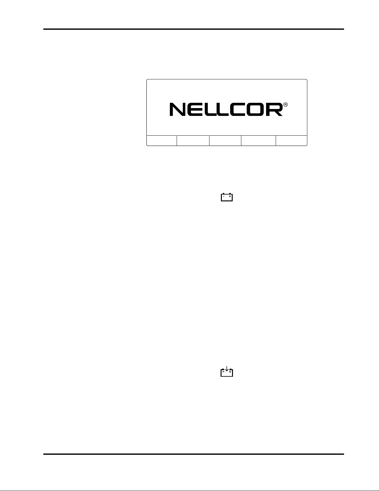
2. With the N-3200 turned off, press the ON/STANDBY button and verify that
an introduction screen similar to the one illustrated in Figure 3-1 is
displayed. (Your N-3200 will have a different software version number than
the one displayed in the illustration.)
28MAR96 10:18
N-3200 SOFTWARE VERSION 1.3.1.002
3.3.2 Battery Charge
DISPLAY
TOP
DISPLAY
BOTTOM
TRENDS
ZOOM
Figure 3-1: Introduction Screen
3. Verify that the BATTERY IN USE/BATTERY LOW indicator lights after
the power-on self-test is completed.
4. Allow the monitor to operate for at least 3 hours, 45 minutes. Verify that
the BATTERY IN USE/BATTERY LOW indicator starts to flash about 15
minutes before the battery fully discharges.
5. Allow the monitor to continue to operate until it automatically powers down
due to the low battery. Verify that the battery operation time was a
minimum of 4 hours.
6. If the monitor passes this test, immediately recharge the battery (paragraph
3.3.2).
Perform this procedure to fully charge the battery or after the battery operation
test (paragraph 3.3.1). This procedure should also be performed, if possible,
before repair work is attempted.
1. Connect the N-3200 to an appropriate AC power source.
2. Ensure that the monitor is off and that the AC power switch on the rear
panel is on. Verify that the BATTERY CHARGING indicator is lit.
3. Charge the battery for at least 14 hours.
3.3.3 Power-up Performance
1. Do not stack any monitors on the N-3200.
2. Connect the N-3200 to a suitable AC power source.
3-2
Page 15
Section 3: Performance Verification
3. Ensure that the AC power switch on the rear panel is on.
4. Observe the N-3200 front panel. With the instrument off, press the
ON/STANDBY button. In order to successfully complete the self-test, the
N-3200 must perform the following sequence.
a. The N-3200 emits three consecutively higher pitched beeps and the
POWER ON indicator lights.
b. The STACKED and BATTERY IN USE/BATTERY LOW indicators
light for a few seconds and then turn off. The POWER ON indicator,
BATTERY CHARGING indicator, and PRINTER ON indicator remain
lit.
During the self-test, the following items are displayed on the screen
(illustrated in Figure 3-1):
• The current date and time are indicated in the upper left-hand
corner. The date and time can be changed using the configuration
mode as described in section 4.
• “NELLCOR” is displayed in the center of the screen.
• The software version number is displayed on a single line beneath
the Nellcor name.
c. At the completion of the self-test, the above items are displayed along
with the following menu.
DISPLAY
TOP
DISPLAY
BOTTOM
TRENDS
ZOOM
NORMAL MODE MAIN MENU
5. Press softkey #3, “DISPLAY TOP”. Verify an audible click. The following
submenu is displayed:
NONE
6. Press softkey #5, “NONE”. The normal mode main menu is displayed again.
DISPLAY
TOP
DISPLAY
BOTTOM
TRENDS
ZOOM
7. Press softkey #4, “DISPLAY BOTTOM”. Verify an audible click. The
following submenu is displayed:
NONE
8. Press softkey #5, “NONE”. The normal mode main menu is displayed.
DISPLAY
TOP
DISPLAY
BOTTOM
TRENDS
ZOOM
3-3
Page 16

Section 3: Performance Verification
9. Press softkey #5, “TRENDS ZOOM”. Verify that a low-pitched tone sounds
and that the display does not change.
3.3.4 Hardware and Software Performance (Service Mode)
The following tests are performed in this section to verify that the N-3200
hardware and software are operating properly.
• 3.3.4.1 Button and Knob Tests
• 3.3.4.2 Display Test
• 3.3.4.3 Printer Tests
• 3.3.4.4 Audio Tests
• 3.3.4.5 Stacked Performance
Use of the service mode is required. Use the following procedure to place the
instrument in the service mode:
1. To enter the service mode, the N-3200 must either be disconnected from
other stacked instruments, or the other instruments must be turned off.
The service mode can be accessed while operating from the N-3200 internal
battery. However, it is recommended that the N-3200 be connected to AC
power while performing the following tests to avoid discharging the battery.
2. While the N-3200 is turned off, simultaneously press and hold the FREEZE
and PRINT buttons and softkey #5 (far right softkey). While pressing and
holding all three buttons, press and release the ON/STANDBY button.
Continue to press the FREEZE button, PRINT button and softkey #5 until
the power-up self-test is complete.
3. The words “SERVICE MODE” are displayed on the top center of the screen.
The current date and time are displayed in the upper left-hand corner of the
screen as indicated in Figure 3-2.
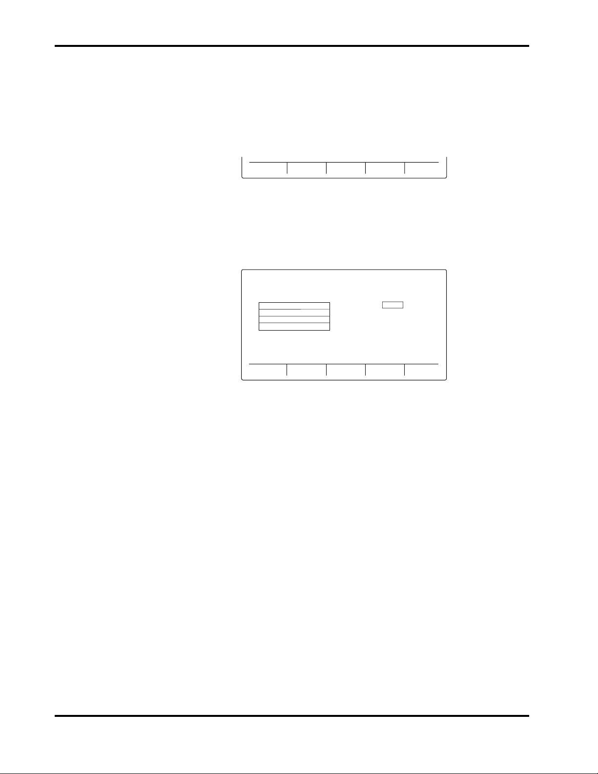
You are now in service mode. The service mode main menu screen is displayed.
12MAY96 09:26 SERVICE MODE
TEST
CONFIG
SERVICE
COMPUTER
Figure 3-2: Service Mode Main Menu Screen
To exit the service mode, power down by pressing the ON/STANDBY button. If
there is no user interaction for 5 minutes while in the service mode, the N-3200
will power down automatically.
Note: The configuration mode, as discussed in Section 4, can be accessed by
pressing softkey #2, “CONFIG”. It is not necessary to enter the
configuration mode to validate hardware and software performance.
3-4
Page 17
Section 3: Performance Verification
Softkey #3, “SERVICE COMPUTER”, of the service mode main menu is
for use by factory service personnel only. If the service computer
function is entered, the N-3200 will not respond to the knob or any
button presses except the ON/STANDBY button. To exit the “Service
Computer” function, power down completely by pressing the
ON/STANDBY button.
Press softkey #1, “TEST”, to display the test submenu.
3.3.4.1 Button and Knob Tests
From the test submenu, press softkey #1, “BUTTON KNOB TEST” to display
the button/knob test screen.
Use the following procedure to test the N-3200 buttons and knob:
1. Press softkey #1 and verify that “SOFTKEY 1” is highlighted. Press
“SOFTKEY 1 again and verify that the highlight disappears. Repeat the
procedure for softkeys 2 through 5.
BUTTON
KNOB TEST
DISPLAY
TEST
PRINTER
TEST
AUDIO
TEST
TEST SUBMENU
29MAR96 06:36 SERVICE MODE
FREEZE
PRINT
PAPER FEED
PRINTER ON/OFF
SOFTKEY 3SOFTKEY 2SOFTKEY 1
KNOB +0
SOFTKEY 4
BACK
Figure 3-3: Button Knob Test Screen
EXIT
SOFTKEY 5
EXIT
Note: If softkey 4 is pressed and held for more than 3 seconds, you will go
“BACK” to the test submenu. If softkey 5 is pressed and held for
more than 3 seconds, you will “EXIT” to the service mode main
menu.
2. Press the FREEZE button on the front panel and verify that the word
“FREEZE” on the display is highlighted, indicating that the button is
operational. Press the FREEZE button again and verify that the highlight
disappears. Repeat the procedure for the PRINT, PRINTER ON/OFF, and
PAPER FEED button.
3. Turn the knob clockwise to increase the “KNOB” count on the display from
“+0” to “+127” and counterclockwise to “-128”, indicating proper operation of
the knob.
4. Press and hold the “BACK” softkey for at least 3 seconds to return to the
test submenu.
3-5
Page 18
Section 3: Performance Verification
3.3.4.2 Display Tests
From the test submenu, press softkey #2, “DISPLAY TEST” to display the
display test submenu.
LED
TEST
GRAPHICS
TEST
BACK EXIT
DISPLAY TEST SUBMENU
Use the following procedure to test the N-3200 display:
1. Press softkey #1, “LED TEST” to display the LED test submenu.
PRINT
PRINTER
ON/OFF
BATT IN
USE
BATT CHRG
BACK
EXIT
LED TEST SUBMENU
Note: If softkey #4 is pressed and held for more than 3 seconds, you will
go “BACK” to the test submenu. If softkey #5 is pressed, you will
“EXIT” to the service mode main menu.
2. Press softkey #1, “PRINT” and verify that the green STACKED indicator
next to the PRINT button lights. Press the “PRINT” softkey again and
verify that the light goes out.
3. Press softkey #2, “PRINTER ON/OFF” and verify that the green PRINTER
ON indicator on the left-side panel lights. Press the “PRINTER ON/OFF”
softkey again and verify that the light goes out.
4. Press softkey #3, “BATT IN USE” and verify that the BATTERY IN
USE/BATTERY LOW indicator on the front panel lights. Press the “BATT
IN USE” softkey again and verify that the indicator goes out.
Note: When operating on DC power, the BATTERY IN USE/BATTERY
LOW indicator goes out when the “LED TEST” softkey is pressed so
that this test can be performed.
5. Press softkey #4, “BATT CHRG” and verify that the BATTERY CHARGING
indicator on the front panel lights. Press the “BATT CHRG” softkey again
and verify that the indicator goes out.
Note: This test can only be performed while operating on DC power.
When operating on AC power, the light should be constantly lit.
6. Press and hold the “BACK” softkey to return to the display test submenu.
3-6
Page 19
Section 3: Performance Verification
7. Press softkey #2, “GRAPHICS TEST” to display the graphics test submenu.
PIXEL
TEST
WAVEFORM
TEST
TEXT
TEST
BACK EXIT
GRAPHICS TEST SUBMENU
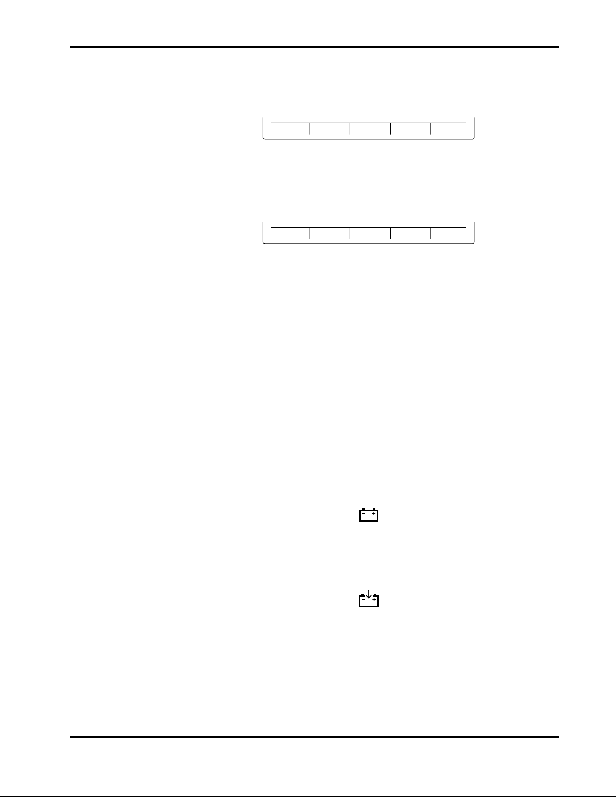
8. From the graphics test submenu, press softkey #1, “PIXEL TEST”. Verify
that one of the patterns of pixels illustrated in Figure 3-4 is displayed. Press
the “PIXEL TEST” softkey again to clear the test pattern.
29MAR96 06:35 SERVICE MODE
WAVEFORMPIXEL
TEST
29MAR96 06:35 SERVICE MODE
TEXT
TEST
BACK
EXIT
TEST TEST TEST
WAVEFORMPIXEL
TEXT
BACK
EXIT
Figure 3-4: Pixel Test Display
Press the “PIXEL TEST” key again to display the alternate pattern. Press
the softkey once more to clear the test pattern. The graphics test submenu
is displayed.
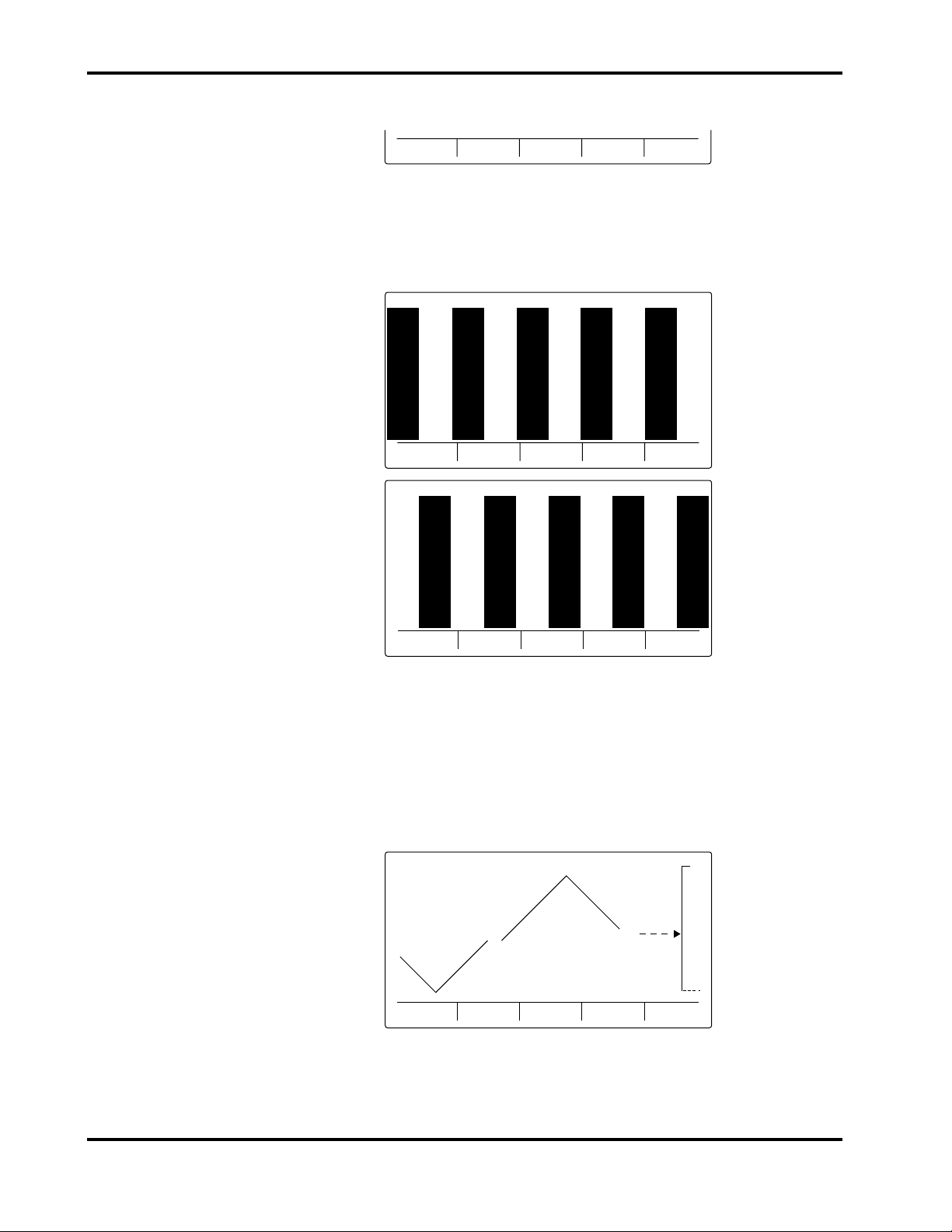
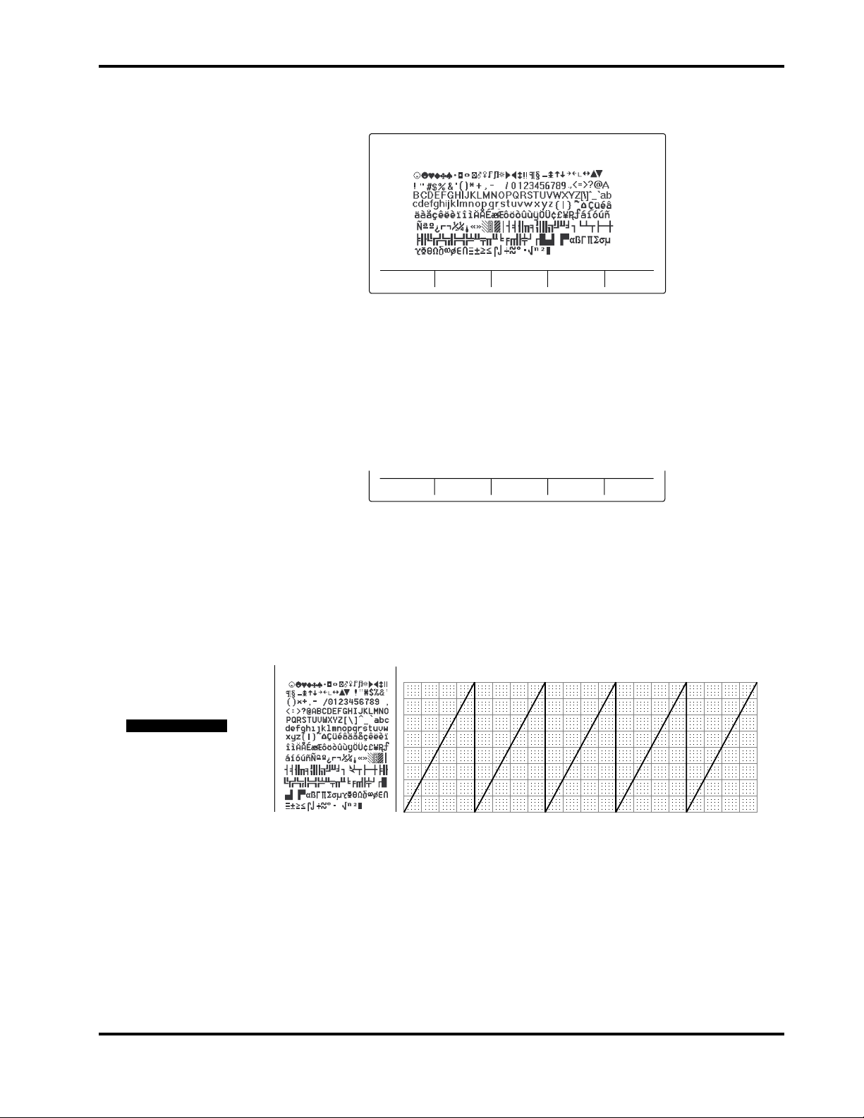
9. Press softkey #2, “WAVEFORM TEST” and verify that a waveform similar
to the one illustrated in Figure 3-5 is displayed. A wiper bar with a sweep
speed of 25 mm/sec is displayed.
29MAR96 06:36 SERVICE MODE
PIXEL
TEST
WAVEFORM
TEST
TEXT
TEST
BACK
EXIT
Figure 3-5: Waveform Test Display
3-7
Page 20
Section 3: Performance Verification
10. Press softkey #3, “TEXT TEST” to display all available text characters.
Verify that the screen is similar to the one illustrated in Figure 3-6.
29MAR96 06:38 SERVICE MODE
3.3.4.3 Printer Tests
31JUN96 4:44 PM
PIXEL
TEST
WAVEFORM
TEST
TEXT
TEST
BACK
EXIT
Figure 3-6: Text Test Display
11. Press the “BACK” softkey to return to the display test submenu. Press it
again to return to the test submenu.
From the test submenu, press softkey #3, “PRINTER TEST” to display the
printer test submenu.
WAVEFORM/
TEXT TEST
WAVEFORM
TEST
TEXT
TEST
BACK EXIT
PRINTER TEST SUBMENU
Ensure that the PRINTER ON indicator on the left-side panel is on. If not, press
the PRINTER ON/OFF button. Use the following procedure to test the N-3200
printer:
1. Press softkey #1, “WAVEFORM TEXT TEST”. Verify that a list of ASCII
characters and a sample waveform print as illustrated in Figure 3-7.
SERVICE MODE TEST SAMPLE
PRINTER TEST
PRINTER TEST
PRINTER TEST
3-8
Figure 3-7: Waveform/Text Test Printout
Note: While the test is printing, a blank screen is displayed with “PRINT
IN PROGRESS” written along the bottom of the screen. To abort
the test in progress, press softkey #5, “ABORT”.
Page 21
Section 3: Performance Verification
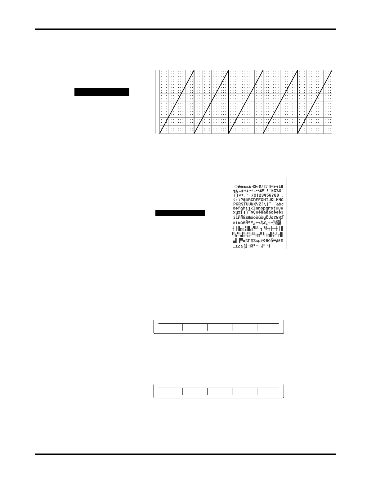
2. Press softkey #2, “WAVEFORM TEST”. Verify that a sample waveform
prints as illustrated in Figure 3-8.
31JUN96 4:44 PM
PRINTER TEST
PRINTER TEST
PRINTER TEST
3. Press softkey #3, “TEXT TEST”. Verify that a list of ASCII characters prints
as illustrated in Figure 3-9.
SERVICE MODE TEST SAMPLE
Figure 3-8: Waveform Test Printout
9AUG96 16:23
PRINTER TEST
PRINTER TEST
PRINTER TEST
3.3.4.4 Audio Tests
Figure 3-9: Text Test Printout
4. Press the “BACK” softkey to return to the test submenu.
From the test submenu, press softkey #4, “AUDIO TEST” to display the audio
test submenu.
KEY
TONES
POWER ON
TONES
ALARM
TONE
BACK EXIT
AUDIO TEST SUBMENU
Use the following procedure to test the N-3200 audio tones:
1. Press softkey #1, “KEY TONES” to display the key tones submenu.
VALID KEY
TONE
INVALID
KEY TONE
BACK EXIT
KEY TONES SUBMENU
2. Press softkey #1, “VALID KEY TONE” and verify that the high-pitched
valid key tone is emitted.
3-9
Page 22

Section 3: Performance Verification
3. Press softkey #2, “INVALID KEY TONE” and verify that the lower-pitched
invalid key tone is emitted.
4. Press the “BACK” softkey to return to the audio test submenu.
5. Press softkey #2, “POWER ON TONES” to display the power on tones
submenu.
6. Press softkey #1, “POWER ON TONE” and verify that three consecutively
higher-pitched beeps are emitted.
7. Press and release softkey #2, “POST PASS TONE”. Verify that a 1-second
beep is emitted.
8. Press softkey #3, “POST FAIL TONE”. Verify that a series of 1-second,
higher-pitched repeating beeps are emitted. Press the softkey again to stop
the beeping.
9. Press the “BACK” softkey to return to the audio test submenu.
10. Press softkey #3, “ALARM TONE” and verify that a single steady tone is
emitted for about 2 seconds.
11. Press the “EXIT” softkey to return to the service mode main menu.
To exit the service mode, power down the N-3200 by pressing the ON/STANDBY
button.
3.3.4.5 Stack Performance, N-3000
POWER ON
TONE
POST PASS
TONE
POST FAIL
TONE
BACK EXIT
POWER ON TONES SUBMENU
The following procedure verifies that the N-3200 is communicating with the
N-3000.
1. Stack the N-3000 patient monitor on top of the N-3200 as described in the
N-3000 or N-3200 operator’s manuals. Do not connect any sensors or ECG
cables to the N-3000.
2. Connect the N-3200 to a suitable AC power source.
3. Ensure that the AC power switch on the N-3200 rear panel is on.
4. With both instruments turned off, press the N-3200 ON/STANDBY button.
Verify that the N-3200 performs the following sequence.
a. The N-3200 emits three consecutively higher pitched beeps and the
POWER ON indicator lights.
b. The BATTERY IN USE/BATTERY LOW indicator lights for a few
seconds and then turns off. The STACKED AND BATTERY
CHARGING indicators light and stay on.
3-10
Page 23
Section 3: Performance Verification
During the self-test, the following items are displayed on the screen
(illustrated in Figure 3-1):
• The current date and time are indicated in the upper left-hand
corner.
• “NELLCOR” is displayed in the center of the screen.
• The software version number is displayed on a single line beneath
the Nellcor name.
c. At the completion of the self-test, the above items are displayed along
with the following menu.
DISPLAY
TOP
DISPLAY
BOTTOM
TRENDS
ZOOM
NORMAL MODE MAIN MENU
5. Press the N-3000 ON/STANDBY button. Verify that the N-3000 performs
the following sequence:
a. The N-3000 emits three consecutively higher pitched beeps.
b. All indicators light for a few seconds. The left-most, middle, and right
displays all indicate “8.8.8.”.
c. All displays turn off momentarily.
d. Digital displays individually light in a scanning, or firefly, test pattern
while the N-3000 power-on self-test is taking place.
e. A single, 1-second beep is produced and all displays again illuminate
momentarily, indicating the automatic power-on self-test is complete.
f. The N-3000 POWER ON indicator is lit. The BATTERY CHARGING
indicator is also illuminated. The displays are blank.
6. Verify that the STACKED indicators on both instruments are illuminated.
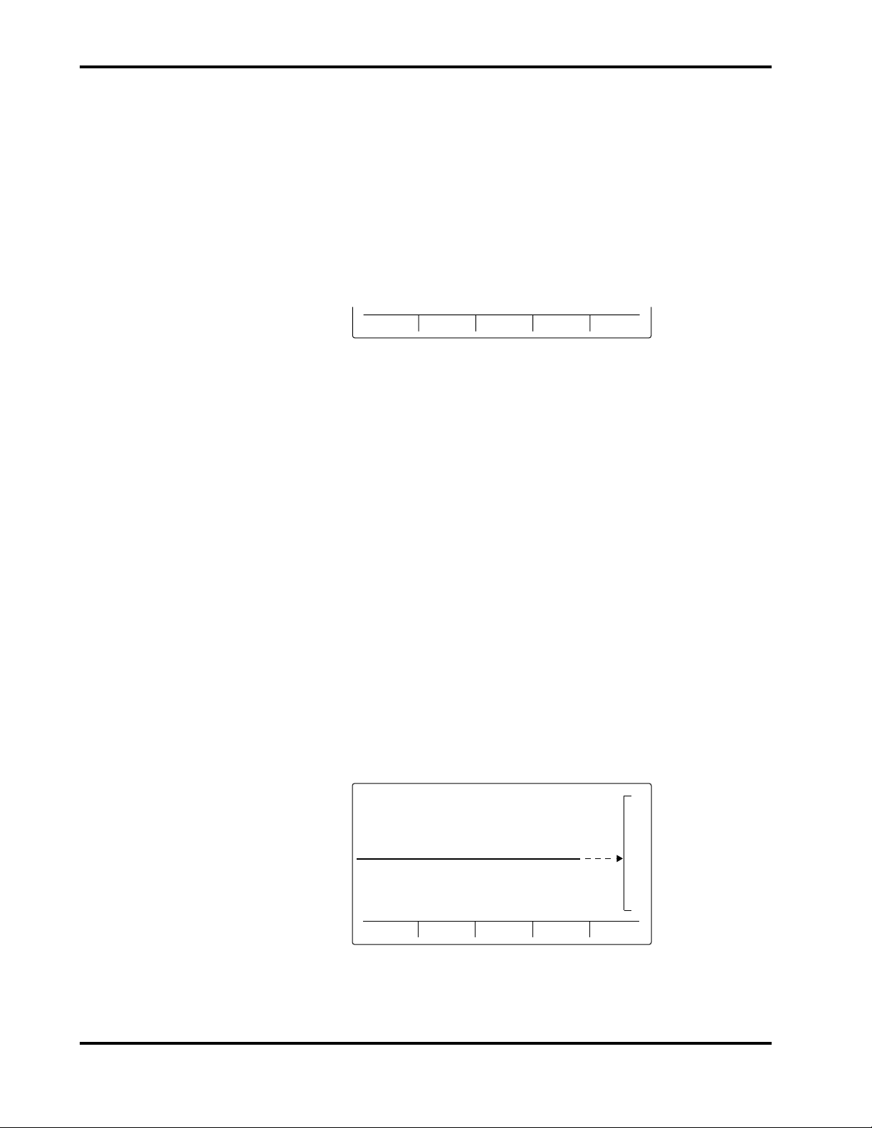
7. Verify that a pleth waveform screen appears, similar to the one illustrated
in Figure 3-10. The N-3000 SpO2 alarm limits on the right-hand side of the
screen will equal the current limits as determined by the N-3000 setting.
29NOV96 06:36 PLETH
PLETHPLETH
DISPLAY
Figure 3-10: Pleth Waveform
TOP
DISPLAY
BOTTOM
TRENDS
ZOOM
100
85
3-11
Page 24

Section 3: Performance Verification
Note: Specific user configurations may result in a different initial display,
8. Turn off both instruments by pressing the ON/STANDBY buttons.
Disconnect the N-3000 from the N-3200 by pressing the docking release
button on the rear panel of the N-3200 and sliding the N-3000 off the stack.
3.3.4.6 Stack Performance, N-3100
The following procedure verifies that the N-3200 is communicating with the
N-3100.
1. Stack the N-3100 blood pressure monitor on top of the N-3200 as described
in the N-3100 or N-3200 operator’s manuals. Do not connect a blood
pressure hose to the N-3100.
2. Connect the N-3200 to a suitable AC power source.
3. Ensure that the AC power switch on the N-3200 rear panel is on.
4. With both instruments turned off, press the N-3200 ON/STANDBY button.
Verify that the N-3200 performs the following sequence.
a. The N-3200 emits three consecutively higher pitched beeps and the
POWER ON indicator lights.
such as ECG, respiration, dual viewing area, etc.
b. The BATTERY IN USE/BATTERY LOW indicator lights for a few
seconds and then turns off. The STACKED AND BATTERY
CHARGING indicators light and stay on.
During the self-test, the following items are displayed on the screen
(illustrated in Figure 3-1):
• The current date and time are indicated in the upper left-hand
corner.
• “NELLCOR” is displayed in the center of the screen.
• The software version number is displayed on a single line beneath
the Nellcor name.
c. At the completion of the self-test, the above items are displayed along
with the following menu.
DISPLAY
TOP
DISPLAY
BOTTOM
TRENDS
ZOOM
NORMAL MODE MAIN MENU
5. Press the N-3100 ON/STANDBY button. Verify that the N-3100 performs
the following sequence:
3-12
a. The N-3100 emits three consecutively higher pitched beeps.
b. All indicators light for a few seconds. The left-most, middle, and right
displays all indicate “8.8.8.”.
c. All displays turn off momentarily.
Page 25

Section 3: Performance Verification
d. Digital displays individually light in a scanning test pattern while the
N-3100 power-on self-test is taking place.
e. A single, 1-second beep is produced and all displays again illuminate
momentarily, indicating the automatic power-on self-test is complete.
f. The N-3100 POWER ON indicator is lit. The MANUAL MODE
indicator is also illuminated. Dashes are displayed in the N-3100
displays.
6. Verify that the STACKED indicators on both instruments are illuminated.
7. Verify that “NIBP” appears at the top center of the screen, similar to the
one illustrated in Figure 3-11.
29NOV96 06:36 NIBP
8. Turn off both instruments by pressing the ON/STANDBY buttons.
3.4 SAFETY TESTS
The following safety tests are required:
• 3.4.1 Ground Integrity Test
• 3.4.2 Electrical Leakage Test
3.4.1 Ground Integrity Test
This test verifies the integrity of the N-3200 power cord ground wire from the
AC plug and the connection with the chassis ground.
1. Configure the ELECTRICAL SAFETY ANALYZER as follows:
NIBP
DISPLAY
TOP
DISPLAY
BOTTOM
TRENDS
ZOOM
Figure 3-11: NIBP Display
Note: Specific user configurations may result in a different initial display,
such as NIBP trends, dual viewing area, etc.
Disconnect the N-3100 from the N-3200 by pressing the docking release
button on the rear panel of the N-3200 and sliding the N-3100 off the stack.
Function: Ground Resistance Test
Range: mΩ (milliohms)
2. Connect the N-3200’s AC plug to the analyzer as recommended in the
analyzer’s operating instructions.
3. Connect the analyzer resistance input lead to the grounding stud on the
rear panel of the N-3200. Verify that the analyzer indicates 100 mΩ or less.
3-13
Page 26

Section 3: Performance Verification
3.4.2 Electrical Leakage Test
The following chassis source test verifies the low level of electrical leakage
current allowed by the N-3200. This test is in compliance with IEC 601-1 and
AAMI Standard ESI, Paragraph 3.3.1, Chassis Source Current, between the
power ground and exposed conductive hardware.
1. Configure the electrical safety analyzer as follows:
Function: Leakage
Range: µA (microamps)
2. Connect the N-3200 AC power cord to the electrical safety analyzer as
recommended by the analyzer operating instructions.
3. Connect the electrical safety analyzer leakage input lead to the N-3200’s
grounding stud on the rear panel.
The ANALYZER leakage indication must not exceed 100 µA for the
following AC power configurations with the monitor on and off.
AC LINE
POLARITY
POWER LINE
GROUND CABLE
Normal Normal
Reverse Normal
Reverse Open
Normal Open
3-14
Page 27

SECTION 4: CONFIGURATION MODE
4.1 Introduction
4.2 Entering the Configuration Mode
4.3 N-3200 Information
4.4 N-3000 Information
4.5 N-3100 Information
4.6 Accessing Configuration Mode from Service Mode
4.1 INTRODUCTION
This section discusses use of the configuration mode to configure power-on
default values and the service mode to test, identify, and correct N-3200
difficulties.
4.2 ENTERING THE CONFIGURATION MODE
The configuration mode can be used to display or print the N-3200 or another
stacked instrument’s error code log, operational information, and power status.
Additionally, the configuration mode allows displaying, changing, and printing
of N-3200 real-time clock settings.
The configuration mode can be used to change power-on default configuration
settings for the N-3200 only. It also allows you to reset all N-3200 power-on
default settings to their original factory values.
The N-3200 can enter the configuration mode while it is operating in a stacked
configuration with other instruments, as long as the other instruments are
turned on and not in the service mode.
Use the following procedure to enter the configuration mode:
1. While the N-3200 is turned off, simultaneously press both the FREEZE and
PRINT buttons and press and release the ON/STANDBY button. Release
the FREEZE and PRINT buttons after the ON/STANDBY has been
released.
2. You are now in configuration mode. The configuration mode main menu is
displayed as illustrated in Figure 4-1. If an N-3000 or N-3100 is not stacked
with the N-3200, the corresponding menu item will be blank.
Note: If, after entering a submenu, no buttons are pressed and the knob
is not turned for 10 seconds, the N-3200 will return to this main
menu:
12DEC95 09:26 CONFIG MODE
N-3100 N-3200N-3000
Figure 4-1: Configuration Mode Main Menu
4-1
Page 28

Section 4: Configuration Mode
To exit the configuration mode, power down by pressing the ON/STANDBY
button. If no buttons are pressed and the knob is not turned for 5 minutes while
the N-3200 is in the configuration mode, the N-3200 will power down
automatically.
Paragraph 4.3 discusses use of the configuration mode to display, change, and
print N-3200 configuration information. Paragraphs 4.4 and 4.5 discuss
procedures used to display and print configuration settings for the N-3000 and
N-3100, respectively.
4.3 N-3200 INFORMATION
From the configuration main menu, press softkey #3, “N-3200”. Page 1 of the
N-3200 information submenu is displayed.
N-3200 INFORMATION SUBMENU - Page 1
Press softkey #5, “NEXT PAGE”, to display page 2 of the N-3200 information
submenu.
N-3200 INFORMATION SUBMENU - Page 2
4.3.1 Configuration Information, N-3200
From page 1 of the N-3200 information submenu, press softkey #1, “CONFIG.
INFO”, to display the current configuration settings for the N-3200. Your screen
may have different institutional (INSTITUT) default settings than the one
illustrated in Figure 4-2. CURRENT settings for the N-3200 are not displayed.
CONFIG
INFO
RESET TO
FACT DFLT
10JAN96 05:41 CONFIG MODE N-3200
TIME FORMAT
DATE FORMAT
LANGUAGE
# DISPLAY ZONES
DISPLAY PRIORITY 1
DISPLAY PRIORITY 2
VALID KEY TONE
ECG LEAD SELECT
ECG VERTICAL SCALE
ERROR
LOG
CONFIGURATION INFORMATION
PARAMETER FACTORY
PAGE
DOWN
SET
RTC
OPERATION
INFO
24 HOUR
DDMMMYY
ENGLISH
PLETH
SELECT
ECG
POWER
STATUS
NEXT
PAGE
INSTITUT CURRENT
24 HOUR
DDMMMYY
ENGLISH
2
ECG
PLETH
ON
1 X
II
ON
.5 X
BACK EXIT
NEXT
PAGE
EXIT
2
II
4-2
Figure 4-2: Configuration Setting Display - Page 1
Page 29

Section 4: Configuration Mode
Press softkey #2, “PAGE DOWN” to view the second page of N-3200
configuration information.
10JAN96 05:42 CONFIG MODE N-3200
ECG VERTICAL SCALE
ECG SWEEP SPEED
RESP VERTICAL SCALE
RESP SWEEP SPEED
PLETH SWEEP SPEED
PRINT ON ALARM
PRINTER POWER ON STATE
TREND TIME SCALE
PRINT CONTRAST VALUE
PAGE
UP
CONFIGURATION INFORMATION
PARAMETER FACTORY
25 mm/s
12.5 mm/s
25 mm/s
8 hrs
SELECT
INSTITUT CURRENT
1 X
1 X
ON
ON
3
1 X
25 mm/s
.5 X
12.5 mm/s
25 mm/s
ON
ON
8 hrs
BACK EXIT
3
Figure 4-3: Configuration Setting Display - Page 2
Press softkey #1, “PAGE UP”, to return to the first page.
Note: Pressing softkey #4, “BACK”, would return you to the N-3200
information submenu, and pressing softkey #5, “EXIT”, would return
you to the configuration main menu.
Rotate the knob to highlight individual institutional configuration settings. If
you wish to change a default setting, first highlight it then press softkey #3,
“SELECT”. The select configurable setting submenu is displayed.
RESET TO
FACT DFLT
SET CANCEL
SELECT CONFIGURABLE SETTING SUBMENU
Press the up and down arrow softkeys ( ) or rotate the knob to scroll
through the institutional default settings for the parameter selected. All possible
settings for each parameter are listed and described in Table 4-1. Press the
“SET” softkey to select the highlighted default setting and return to the
configuration information display. Pressing the “CANCEL” softkey returns you
to the configuration information display without changing any settings. Pressing
the “RESET TO FACT DFLT” softkey sets the highlighted parameter to the
factory default setting, as indicated in the FACTORY column of the display.
Table 4-1: N-3200 Configuration Settings
Factory
Setting and Description
Default
Institutional Default Selections
Setting
Time format - format used to
display time on the screen
Date format - format used to
display time on the screen
Language - language used
for display
Display zones - number of
HH:MM:SS
HH:MM:SS (12 or 24 hour)
(24 hour)
DD MMMYYDD MMM YYY DD.MM.YY
MM-DD-YY
English English, French, German, Italian,
Spanish, Portuguese, Dutch
2 1 or 2
parameters that can be
displayed simultaneously
4-3
Page 30

Section 4: Configuration Mode
Setting and Description
Table 4-1: N-3200 Configuration Settings - Continued
Factory
Default
Institutional Default Selections
Setting
Display priority #1 parameter displayed on top
viewing area when entering
the main menu from powerup
Display priority #2 parameter displayed on
bottom viewing area when
entering the main menu
from power-up
Valid key tone - beep that
sounds when a valid button
is pressed
ECG lead select - I (RA-LA),
II (RA-LL), or III (LA-LL)
ECG vertical scale - vertical
scale for ECG waveforms
ECG sweep speed - sweep
speed for ECG waveforms
Resp vertical scale - vertical
scale for respiration
waveforms
ECG wave ECG wave, pleth wave, resp wave,
SpO2 trend, pulse rate trend
(optically-derived), heart rate
trend, resp trend, pulse amplitude
trend, last 10 NIBP
measurements, NIBP trend, none
Pleth wave (same as listed in display priority
#1 above)
On Off, on
II I, II, or III
1X .25X, .5X, 1X, 2X, 4X, or 8X
25 mm/sec 6.25, 12.5, or 25 mm/sec
1X .25X, .5X, 1X, 2X, 4X, or 8X
Resp sweep speed - sweep
speed for respiration
waveforms
Pleth sweep speed - sweep
speed for plethysmographic
waveforms
Print on alarm - automatic
printing of screen when
alarm sounds (except low
battery or microprocessor/
power fail alarms)
Printer power on state state of PRINTER POWER
ON/OFF button after the
N-3200 is turned on
Trend time scale - scale of
displayed trend
Print contrast value - print
intensity increases from 0
(lightest) to 10 (darkest)
12.5
6.25, 12.5, or 25 mm/sec
mm/sec
25 mm/sec 6.25, 12.5, or 25 mm/sec
On Off, on
On Off, on
8 Hours 30 minutes, 1, 2, 4, 8, 12, or 24
hours
3 0 through 10
4-4
Page 31

4.3.2 Error Log, N-3200
Section 4: Configuration Mode
From page 1 of the N-3200 information submenu, press softkey #2, “ERROR
LOG”, to display the error log for the N-3200. Your screen may have different
error information than the one illustrated in Figure 4-4.
29NOV95 11:52 CONFIG MODE N-3200
# COUNT
0
1
2
3
4
5
6
7
8
ERROR LOG INFORMATION
ERROR CODETIME INSTANCE
0054
1A
0119
02
0000
03
0000
03
0000
00
0000
00
0000
00
0000
00
0000
00
PAGE
DOWN
3C39
3C54
0000
0000
0000
0000
0000
0000
0000
00 39 FF FF FF
12 00 44 44 33
00 00 00 00 00
00 00 00 00 00
00 00 00 00 00
00 00 00 00 00
00 00 00 00 00
00 00 00 00 00
00 00 00 00 00
BACK EXIT
Figure 4-4: Error Log Display - Page 1
Press softkey #2, “PAGE DOWN”, to display page 2 of the error log display.
29NOV95 11:52 CONFIG MODE N-3200
# COUNT
8
9
PAGE
UP
ERROR LOG INFORMATION
00000000
ERROR CODETIME INSTANCE
0000
0000
0000
00 00 00 00 00
00 00 00 00 00
BACK EXIT
Figure 4-5: Error Log Display - Page 2
Numbers displayed in the error log are hexadecimal numbers.
The error log lists the last 10 error codes (0 = most recent) encountered by the
N-3200. The “COUNT” column lists the number of times the error occurred and
the “TIME” column indicates the total number of operating hours on the N-3000
when the error last occurred.
The information contained in the error log may be requested by Nellcor Puritan
Bennett Technical Services personnel if a problem has arisen that necessitates
calling them. If necessary, the screens may be printed and faxed to them for
analysis.
4-5
Page 32

Section 4: Configuration Mode
4.3.3 Operation Information, N-3200
From page 1 of the N-3200 information submenu, press softkey #3,
“OPERATION INFO”, to display the operational information for the N-3200.
The following information is displayed:
• INSTRUMENT TYPE - N-3200
• INSTRUMENT ID - The IID is a hexadecimal number corresponding to the
instrument identifier. This number should agree with the address label on
the outside of the instrument. However, the label and the internal value
may disagree if the N3200 UIF module was replaced and the external label
was not changed.
10JAN96 05:55 CONFIG MODE N-3200
INSTRUMENT OPERATION INFORMATION
INSTRUMENT TYPE
INSTRUMENT ID
CONFIGURATION CODE
SOFTWARE VERSION
TOTAL HOURS OF OPERATION
N-3200
01125AA5
00
1.3.1.002
86
BACK EXIT
Figure 4-6: N-3200 Operation Info Display
• CONFIGURATION CODE - 00
• SOFTWARE VERSION - The first digit represents the software version
number. The next two digits are the major software revision number. The
minor software revision number is represented by the last three digits.
• TOTAL HOURS OF OPERATION - This number indicates the total number
of operating hours logged by the unit since it was produced.
4.3.4 Power Status Information, N-3200
From page 1 of the N-3200 information submenu, press softkey #4, “POWER
STATUS”, to display the power status information for the N-3200.
10JAN96 05:56 CONFIG MODE N-3200
POWER STATUS INFORMATION
POWER BUS VOLTAGE
LITHIUM STATUS
14.55
PASS
BACK EXIT
Figure 4-7: N-3200 Power Status Display
4-6
The first line displays the voltage of the power bus and the second line indicates
whether the lithium battery needs to be replaced (“FAIL”) or not (“PASS”).
Page 33

4.3.5 Printing N-3200 Configuration Mode Information
To print N-3200 configuration mode information, you must have entered the
configuration mode and pressed the “N-3200” softkey from the main menu
(Figure 4-1). If the “PRINT” button is then pressed from any submenu, the
instrument operation, power status, error log, and configuration information for
the N-3200 is printed. The printout will be similar to the one illustrated in
Figure 4-8.
Section 4: Configuration Mode
4AUG95 11:24
INSTRUMENT OPERATION INFORMATION
INSTRUMENT TYPE
INSTRUMENT ID
CONFIGURATION CODE
SOFTWARE VERSION
TOTAL HOURS OF OPERATION
POWER BUS VOLTAGE
LITHIUM STATUS
CONFIGURATION INFORMATION
PARAMETER
TIME FORMAT
DATE FORMAT
LANGUAGE
# DISPLAY ZONES
DISPLAY PRIORITY 1
DISPLAY PRIORITY 2
VALID KEY TONE
ECG LEAD SELECT
ECG VERTICAL SCALE
ECG SWEEP SPEED
4.3.6 Reset to Factory Defaults, N-3200
ERROR LOG INFORMATION
FACTORY
24 HOUR
DDMMMYY
ENGLISH
ECG
PLETH
1 X
25 mm/s
INSTITUT
2
ON
II
01125AA5
1.3.1.010
24 HOUR
DDMMMYY
ENGLISH
ECG
PLETH
ON
II
1 X
25 mm/s
N-3200
00
165
14.55
PASS
CURRENT
2
#
COUNT
0
77
1
02
2
02
3
01
4
02
5
00
6
00
7
00
8
00
9
00
CONFIGURATION INFORMATION
PARAMETER
RESP VERTICAL SCALE
RESP SWEEP SPEED
PLETH SWEEP SPEED
PRINT ON ALARM
PRINTER POWER ON STATE
TREND TIME SCALE
PRINT CONTRAST VALUE
TIME
009C
0000
004C
007D
007D
0600
0700
0800
0900
0000
ERROR CODE
3C39
BC02
3C54
3C39
BC56
0000
0000
0000
0000
0000
INSTANCE
00 39 FF FF FF
15 0B 52 50 53
12 00 44 44 33
14 00 50 45 52
00 00 00 00 00
00 00 00 00 00
00 00 00 00 00
00 00 00 00 00
00 00 00 00 00
00 00 00 00 00
FACTORY
1 X
12.5mm/s
25 mm/s
8 hrs
Figure 4-8: N-3200 Configuration Mode Printout
RESET TO
FACT DFLT
SET
RTC
NEXT
PAGE
EXIT
INSTITUT CURRENT
1 X
12.5mm/s
25 mm/s
ON
ON
ON
ON
8 hrs
3
10
N-3200 INFORMATION SUBMENU - Page 2
From page 2 of the N-3200 information submenu, press softkey #1, “RESET TO
FACT DFLT”, to return all configuration mode parameters to their factory
default settings.
Three beeps indicate that the process is complete.
4.3.7 Real-time Clock Information, N-3200
To set the real-time clock, (RTC) from the configuration mode main menu
(Figure 4-1), press the “N-3200” softkey. Page 1 of the N-3200 information
submenu is displayed.
N-3200 INFORMATION SUBMENU - Page 1
CONFIG
INFO
ERROR
LOG
OPERATION
INFO
POWER
STATUS
NEXT
PAGE
4-7
Page 34

Section 4: Configuration Mode
Press softkey #5, “NEXT PAGE”, to display page 2.
RESET TO
FACT DFLT
SET
RTC
NEXT
PAGE
EXIT
N-3200 INFORMATION SUBMENU - Page 2
From page 2 of the N-3200 information submenu, press softkey #2, “SET RTC”,
to display the RTC information for the N-3200.
12OCT95 05:58 CONFIG MODE N-3200
REAL TIME CLOCK INFORMATION
DATE -- MONTH
DATE -- DAY
DATE -- YEAR
TIME -- HOUR
TIME -- MINUTE
TIME -- SECOND
SELECT
BACK
10
12
95
5
58
39
EXIT
Figure 4-9: N-3200 RTC Display
Rotate the knob to highlight the time and date parameters. Press softkey #3,
“SELECT”, to select a highlighted item you wish to change. The RTC select
configurable setting submenu is displayed.
SET CANCEL
RTC SELECT CONFIGURABLE SETTING SUBMENU
Press the up and down arrow softkeys or rotate the knob to scroll through the
date or time settings. Press the “SET” softkey to set the selected variable or
“CANCEL” to return to the RTC display without changing any variables.
Press “BACK” to return to page 2 of the N-3200 information submenu or “EXIT”
to return to the configuration main menu.
4.4 N-3000 INFORMATION
Configuration settings for an attached, active N-3000 may be displayed and
printed by the N-3200. From the configuration main menu, press softkey #1,
“N-3000”. The N-3000 information submenu is displayed.
4.4.1 Configuration Information, N-3000
Note: Refer to the N-3000 service manual for a more detailed discussion of
N-3000 configuration settings.
From the N-3000 information submenu, press softkey #1, “CONFIG. INFO”, to
access the N-3000 configuration submenu. The submenu displayed depends on
CONFIG
INFO
ERROR
LOG
OPERATION
INFO
POWER
STATUS
EXIT
N-3000 INFORMATION SUBMENU
4-8
Page 35

Section 4: Configuration Mode
the model of N-3000 you have. If the N-3000 measures SpO2, but not ECG, the
following submenu is displayed.
N3000
UIF
N3000
SPO2
BACK EXIT
N-3000 CONFIGURATION SUBMENU (SPO2)
If the N-3000 measures SpO2 and ECG, the following submenu is displayed.
N3000
UIF
N3000
SPO2
N3000
ECG
BACK EXIT
N-3000 CONFIGURATION SUBMENU (SPO2/ECG)
If the N-3000 measures SpO2, ECG and RESP, the following submenus is
displayed.
N3000
UIF
N3000
SPO2
N3000
ECG
N3000
RESP
NEXT
PAGE
N-3000 CONFIGURATION SUBMENU (SPO2/ECG/RESP)
Page 2 of the SpO2, ECG and RESP submenu allows you to back up one
submenu or exit.
NEXT
PAGE
BACK EXIT
N-3000 CONFIGURATION SUBMENU (SPO2/ECG/RESP)
Pressing the PRINT button anytime after accessing the N-3000 configuration
submenu prints all configuration settings, the error log, and operation and
power status information.
4.4.1.1 UIF Configuration Information, N-3000
From page 1 of the N-3000 configuration submenu, press softkey #1, “N3000
UIF”, to display the N-3000 UIF (user interface) configuration settings.
FACTORY default settings, INSTITUT default settings (i.e., changes your
institution has made to the factory default settings), and CURRENT settings are
displayed.
Your screen may have different settings from the one illustrated in Figure 4-10.
10JAN96 05:40 CONFIG MODE N-3000
PULSE BEEP VOLUME
PRIMARY PULSE SOURCE
LATCHING ALARMS
AUDIBLE ALARM VOLUME
AUDIBLE ALARM REMINDER
ALARM SILENCE PERIOD
INSTRUMENT CONFIG CODE
CONFIGURATION INFORMATION
PARAMETER FACTORY
ECG
OFF
INSTITUT CURRENT
6
ECG
OFF
8
ON
60
03
ON
90
BACK EXIT
ECG
7
8
90
7
8
Figure 4-10: N-3000 UIF Configuration Setting Display
4-9
Page 36

Section 4: Configuration Mode
Pressing softkey #4, “BACK”, returns you to the N-3000 information submenu,
and pressing softkey #5, “EXIT”, returns you to the configuration main menu.
4.4.1.2 SpO2 Configuration Information, N-3000
From page 1 of the N-3000 configuration submenu, press softkey #2, “N3000
SPO2”, to display the N-3000 SpO2 configuration settings. Your screen may have
different institutional default and current settings from the one illustrated in
Figure 4-11.
10JAN96 05:41 CONFIG MODE N-3000
ADULT SPO2 HIGH LIMIT
ADULT SPO2 LOW LIMIT
ADULT PR HIGH LIMIT
ADULT PR LOW LIMIT
NEONATE SPO2 HIGH LIMIT
NEONATE SPO2 LOW LIMIT
NEONATE PR HIGH LIMIT
NEONATE PR LOW LIMIT
SpO2 MODE
CONFIGURATION INFORMATION
PARAMETER FACTORY
ADULT
PAGE
DOWN
INSTITUT CURRENT
100
170
190
85
40
95
80
90
100
170
190
ADULT
BACK EXIT
100
85
40
96
84
90
170
ADULT
85
40
Figure 4-11: N-3000 SpO2 Configuration Setting Display - Page 1
Current neonate settings are not displayed if the N-3000 is in the adult mode.
Current adult settings are not displayed if the N-3000 is in the neonate mode.
10JAN96 05:41 CONFIG MODE N-3000
SpO2 MODE
RCAL TYPE 0
PAGE
UP
CONFIGURATION INFORMATION
PARAMETER FACTORY
ADULT ADULT ADULT
INSTITUT CURRENT
1
BACK EXIT
Figure 4-12: N-3000 SpO2 Configuration Setting Display - Page 2
Press the PRINT button to print both pages of the configuration setting display.
4.4.1.3 ECG Configuration Information, N-3000
From page 1 of the N-3000 configuration submenu, press softkey #3, “N3000
ECG”, to display the N-3000 ECG configuration settings. Your screen may have
different settings from the one illustrated in Figure 4-13.
4-10
Page 37

Section 4: Configuration Mode
10JAN96 06:11 CONFIG MODE N-3000
ADULT HR HIGH LIMIT
ADULT HR LOW LIMIT
NEONATE HR HIGH LIMIT
NEONATE HR LOW LIMIT
ECG MODE
ECG LEAD SELECT
ECG ELF FILTER SELECT
ECG PACER FILTER SELECT
Figure 4-13: N-3000 ECG Configuration Setting Display
Current neonate settings are not displayed if the N-3000 is in the adult mode.
Likewise, current adult settings are not displayed if the N-3000 is in the neonate
mode.
4.4.1.4 RESP Configuration Information, N-3000
From page 1 of the N-3000 configuration submenu, press softkey #4, “N3000
RESP”, to display the N-3000 RESP configuration settings. Your screen may
have different settings from the one illustrated below.
10JAN96 05:40 CONFIG MODE N-3000
ADULT RESP HIGH LIMIT
ADULT RESP LOW LIMIT
ADULT APNEA TIME OUT
NEONATE RESP HIGH LIMIT
NEONATE RESP LOW LIMIT
NEONATE APNEA TIME OUT
RESPIRATION MODE
CONFIGURATION INFORMATION
PARAMETER FACTORY
10 SEC
OFF
OFF
CONFIGURATION INFORMATION
PARAMETER FACTORY
ADULT
INSTITUT CURRENT
170
190
40
90
40
20
80
20
15
170
190
5 SEC
II
OFF
OFF
BACK EXIT
INSTITUT CURRENT
4
ADULT
160
5 SEC
OFF
OFF
ADULT
40
II
40
4
20
40
90
II
40
4
20
80
20
15
4.4.2 Error Log, N-3000
BACK EXIT
Figure 4-14: N-3000 RESP Configuration Setting Display
Note: In the US, the parameters “ADULT APNEA TIME OUT” and
“NEONATE APNEA TIME OUT” displayed on the N-3200 as shown in
Figure 4-14 indicate the N-3000 configurations of ADULT
RESPIRATION NOISE TIMEOUT and NEONATE RESPIRATION
NOISE TIMEOUT, respectively.
From page 1 of the N-3000 information submenu, press softkey #2, “ERROR
LOG”, to display the error log for the N-3200. Your screen may have different
error information from the one illustrated in Figure 4-15.
4-11
Page 38

Section 4: Configuration Mode
29NOV95 11:45 CONFIG MODE N-3000
# COUNT
0
1
2
3
4
5
6
7
8
ERROR LOG INFORMATION
ERROR CODETIME INSTANCE
01
01
03
03
00
00
00
00
00
01B8
01C9
024B
024B
02A9
0000
0000
0000
0000
PAGE
DOWN
3C39
3C35
BCF3
BC60
3C35
0000
0000
0000
0000
00 39 FF FF FF
18 07 01 62 32
08 2C 4D 4F 44
45 55 49 46 43
25 4D 1F 39 A8
00 00 00 00 00
00 00 00 00 00
00 00 00 00 00
00 00 00 00 00
BACK EXIT
Figure 4-15: N-3000 Error Log Display - Page 1
Press softkey #2, “PAGE DOWN”, to display page 2 of the error log display.
29NOV95 11:47 CONFIG MODE N-3000
# COUNT
8
9
PAGE
UP
ERROR LOG INFORMATION
00000000
ERROR CODETIME INSTANCE
0000
0000
0000
00 00 00 00 00
00 00 00 00 00
BACK EXIT
The N-3000 error log contains information similar to the N-3200 error log
described in paragraph 4.3.2. The information can by used by Nellcor Puritan
Bennett Technical Services personnel to analyze N-3000 problems.
4.4.3 Operation Information, N-3000
From page 1 of the N-3000 information submenu, press softkey #3,
“OPERATION INFO”, to display the operational information for the N-3000.
The information displayed is described in the service mode section of the N-3000
service manual. It is similar to the N-3200 operation information in paragraph
4.3.3.
Figure 4-16: N-3000 Error Log Display - Page 2
10JAN96 05:42 CONFIG MODE N-3000
INSTRUMENT OPERATION INFORMATION
INSTRUMENT TYPE
INSTRUMENT ID
CONFIGURATION CODE
UIF SOFTWARE VERSION
SpO2 SOFTWARE VERSION
TOTAL HOURS OF OPERATION
N-3000
80100001
03
3.4.0.001
3.3.1.004
891
BACK EXIT
Figure 4-17: N-3000 Operation Info Display
4-12
The type of N-3000 monitor is designated by the “CONFIGURATION CODE”, as
defined in Table 4-2.
Page 39

ICC
Value Monitor Configuration
03 SpO2 only, with serial port
07 SpO2 and ECG only, with serial port
0F SpO2, ECG and respiration, with serial port
12 SpO2 only, with wired network interface
16 SpO2 and ECG only, with wired network interface
1E SpO2, ECG, and respiration, with wired network interface
FF Invalid configuration
4.4.4 Power Status Information, N-3000
From page 1 of the N-3000 information submenu, press softkey #4, “POWER
STATUS”, to display the power status information for the N-3000.
Section 4: Configuration Mode
Table 4-2: N-3000 Configuration Codes
10JAN96 05:48 CONFIG MODE N-3000
POWER STATUS INFORMATION
POWER BUS VOLTAGE
LITHIUM STATUS
15.01
PASS
The first line displays the voltage of the power bus and the second line indicates
whether the lithium battery needs to be replaced (“FAIL”) or not (“PASS”).
4.5 N-3100 INFORMATION
Configuration settings for an attached, active N-3100 may be displayed and
printed by the N-3200. From the configuration main menu, press softkey #2,
“N-3100”. The N-3100 information submenu is displayed.
4.5.1 Configuration Information, N-3100
Refer to the N-3100 service manual for a more detailed discussion of N-3100
configuration settings.
BACK EXIT
Figure 4-18: N-3000 Power Status Display
CONFIG
INFO
ERROR
LOG
OPERATION
INFO
POWER
STATUS
EXIT
N-3100 INFORMATION SUBMENU
4-13
Page 40

Section 4: Configuration Mode
From the N-3100 information submenu, press softkey #1, “CONFIG. INFO”, to
access the N-3100 configuration submenu.
N3100
N-3100 CONFIGURATION SUBMENU
Pressing the PRINT button anytime after accessing the N-3100 configuration
submenu, prints all configuration settings, the error log, and operation and
power status information.
4.5.1.1 UIF Configuration Information, N-3100
From the N-3100 configuration submenu, press softkey #1, “N3100 UIF”, to
display the N-3100 UIF configuration settings. Your screen may have different
institutional (“INSTITUT”) default and current settings from the one illustrated
in Figure 4-19.
29NOV95 03:23 CONFIG MODE N-3100
MEAS COMPLETE REMINDER
AUDIBLE ALARM VOLUME
AUDIBLE ALARM REMINDER
ALARM SILENCE PERIOD
INSTRUMENT CONFIG CODE
UIF
N3100
NIBP
CONFIGURATION INFORMATION
PARAMETER FACTORY
BACK EXIT
INSTITUT CURRENT
ON
ON
60
00
ON
5
ON
60
BACK EXIT
5
5
60
Figure 4-19: N-3100 UIF Configuration Setting Display
Pressing softkey #4, “BACK”, returns you to the N-3100 information submenu,
and pressing softkey #5, “EXIT”, returns you to the configuration main menu.
4.5.1.2 NIBP Configuration Information, N-3100
From the N-3100 configuration submenu, press softkey #2, “N3100 NIBP”, to
display the N-3100 NIBP configuration settings. Your screen may have different
institutional default and current settings than the one illustrated in Figure 4-20.
29NOV95 03:25 CONFIG MODE N-3100
NIBP MODE
MEASUREMENT INTERVAL
ADULT SYS HIGH LIMIT
ADULT SYS LOW LIMIT
ADULT DIA HIGH LIMIT
ADULT DIA LOW LIMIT
ADULT MAP HIGH LIMIT
ADULT MAP LOW LIMIT
ADULT PR HIGH LIMIT
Figure 4-20: N-3100 NIBP Configuration Setting Display - Page 1
Current neonate settings are not displayed if the N-3000 is in the adult mode.
Current adult settings are not displayed if the N-3000 is in the neonate mode.
CONFIGURATION INFORMATION
PARAMETER FACTORY
PAGE
DOWN
ADULT
MANUAL
INSTITUT CURRENT
ADULT
MANUAL
240
210
225
170
70
50
55
240
210
225
170
BACK
70
50
55
ADULT
MANUAL
240
210
225
170
EXIT
70
55
58
4-14
Page 41

Section 4: Configuration Mode
29NOV95 03:25 CONFIG MODE N-3100
ADULT PR HIGH LIMIT
ADULT PR LOW LIMIT
NEONATE SYS HIGH LIMIT
NEONATE SYS LOW LIMIT
NEONATE DIA HIGH LIMIT
NEONATE DIA LOW LIMIT
NEONATE MAP HIGH LIMIT
NEONATE MAP LOW LIMIT
NEONATE PR HIGH LIMIT
PAGE
UP
CONFIGURATION INFORMATION
PARAMETER FACTORY
PAGE
DOWN
INSTITUT CURRENT
170
120
230
40
50
80
30
95
45
170
120
170
BACK
170
40
50
80
30
95
45
40
EXIT
Figure 4-21: N-3100 NIBP Configuration Setting Display - Page 2
29NOV95 03:26 CONFIG MODE N-3100
NEONATE PR HIGH LIMIT
NEONATE PR LOW LIMIT
NIBP ALGORITHM
BP PUMP VERSION
PAGE
UP
CONFIGURATION INFORMATION
PARAMETER FACTORY
INSTITUT CURRENT
230
40
02
230
1
BACK
40
02
EXIT
Figure 4-22: N-3100 NIBP Configuration Setting Display - Page 3
Press the PRINT button to print both pages of the configuration setting display.
4.5.2 Error Log, N-3100
From the N-3100 information submenu, press softkey #2, “ERROR LOG”, to
display the error log for the N-3100. Your screen will display a table similar to
the N-3000 error log display (Figures 4-15 and 4-16). The information can be
used by Nellcor Puritan Bennett Technical Services personnel to analyze N-3100
problems.
4.5.3 Operation Information, N-3100
From the N-3100 information submenu, press softkey #3, “OPERATION INFO”,
to display the operational information for the N-3100.
29NOV95 06:28 CONFIG MODE N-3100
INSTRUMENT OPERATION INFORMATION
INSTRUMENT TYPE
INSTRUMENT ID
CONFIGURATION CODE
SOFTWARE VERSION
TOTAL HOURS OF OPERATION
N-3100
02110001
00
2.4.0.003
1059
BACK EXIT
Figure 4-23: N-3100 Operation Info Display
The information displayed is described in the service mode section of the N-3100
service manual. It is similar to the N-3200 operation information in paragraph
4.3.3 of this manual.
4-15
Page 42

Section 4: Configuration Mode
4.5.4 Power Status Information, N-3100
From the N-3100 information submenu, press softkey #4, “POWER STATUS”, to
display the power status information for the N-3100.
29NOV95 06:33 CONFIG MODE N-3100
POWER STATUS INFORMATION
POWER BUS VOLTAGE
LITHIUM STATUS
12.02
PASS
Figure 4-24: N-3100 Power Status Display
The first line displays the voltage of the power bus and the second line indicates
whether the lithium battery needs to be replaced (“FAIL”) or not (“PASS”).
4.6 ACCESSING CONFIGURATION MODE FROM SERVICE MODE
Configuration mode settings can be viewed and changed while in the service
mode. The service mode is accessed by following the procedures in paragraph
3.3.4, Hardware and Software Performance (Service Mode).
The service mode main menu is displayed after entering the service mode.
TEST CONFIG
SERVICE
COMPUTER
SERVICE MODE MAIN MENU
From the service mode main menu, press softkey #2, “CONFIG”. Page 1 of the
N-3200 information submenu is displayed.
CONFIG
INFO
ERROR
LOG
OPERATION
INFO
BACK
POWER
STATUS
EXIT
NEXT
PAGE
4-16
N-3200 INFORMATION SUBMENU - Page 1
Refer to paragraph 4.3, “N-3200 Information”, for a discussion of N-3200
configuration settings.
To return to the service mode main menu, press softkey #5, “NEXT PAGE”.
From page 2 of the N-3200 information submenu, press softkey #5, “EXIT”.
Page 43

SECTION 5: TROUBLESHOOTING
5.1 Introduction
5.2 How to Use this Section
5.3 Who Should Perform Repairs
5.4 Replacement Level Supported
5.5 Obtaining Replacement Parts
5.6 Troubleshooting Guide
5.1 INTRODUCTION
This section explains how to troubleshoot the N-3200 if problems arise. Tables
are supplied that list possible difficulties, probable causes, and recommended
actions to correct the difficulties.
5.2 HOW TO USE THIS SECTION
Use this section in conjunction with Section 3, Performance Verification, and
Section 7, Spare Parts. To remove and replace a part you suspect is defective,
follow the instructions in Section 6, Disassembly Guide. The circuit analysis
section in the Technical Supplement offers information on how the N-3200
functions.
5.3 WHO SHOULD PERFORM REPAIRS
Only qualified service personnel should open the N-3200 housing, remove and
replace components, or make adjustments. If your medical facility does not have
qualified service personnel, contact Nellcor Puritan Bennett Technical Services
or your local representative.
5.4 REPLACEMENT LEVEL SUPPORTED
The replacement level supported for this product is to the printed circuit board
(PCB) and major subassembly levels. Once you isolate a suspected PCB, follow
the procedures in Section 6, Disassembly Guide, to replace the PCB with a
known good PCB. Check to see if the trouble symptom disappears and the
N-3200 passes all performance tests. If the trouble symptom persists, swap back
the replacement PCB with the suspected malfunctioning PCB (the PCB that was
installed when you started troubleshooting) and continue troubleshooting as
directed in this section.
5.5 OBTAINING REPLACEMENT PARTS
Nellcor Puritan Bennett Technical Services provides technical assistance
information and replacement parts. To obtain replacement parts, contact Nellcor
Puritan Bennett. Refer to parts by the part names and part numbers listed in
Section 7, Spare Parts.
5.6 TROUBLESHOOTING GUIDE
Problems with the N-3200 are separated into the categories indicated in
Table 5-1. Refer to the paragraph indicated for further troubleshooting
instructions.
5-1
Page 44

Section 5: Troubleshooting
Note: Taking the recommended actions discussed in this section will correct
Problem Area Refer to Paragraph
the majority of problems you will encounter. However, problems not
covered here can be resolved by contacting Nellcor Puritan Bennett
Technical Services or your local representative.
Table 5-1: Problem Categories
1. AC Power
5.6.1
• No power-up
• Fails power-on self-test
2. Error Codes 5.6.2
3. Buttons
5.6.3
• N-3200 does not respond properly to the knob or
buttons
4. Display/Audible
5.6.4
• Display does not respond properly
• Audible tones do not sound properly, are generated
without apparent cause, or are not properly
generated in other stacked instruments
5. Operational
5.6.5
• Display appears to be operational, but data is not
displayed
• Suspect readings
• Faulty printer operation
5-2
6. Stacked Operation
5.6.6
• N-3200 not communicating properly with other
instruments
Each of the categories in Table 5-1 are discussed in paragraphs 5.6.1 through
5.6.6.
Page 45

5.6.1 Power
Section 5: Troubleshooting
Most AC power problems result in no response when the ON/STANDBY button
is pressed. Refer to Table 5-2.
Table 5-2: Power Problems
Condition Recommended Action
1. When operating on
AC power the
N-3200 fails to
power-up when the
ON/STANDBY
button is pressed.
2. When operating on
DC power the
N-3200 fails to
power-up when the
ON/STANDBY
button is pressed.
1. Ensure that the power cord is plugged into an
operational AC outlet and the N-3200.
2. Ensure that the AC power switch on the rear
panel is on (press the right side of the rocker
switch).
3. Check the AC inlet fuse. The fuse is accessible
from the rear panel as indicated in paragraph 6.2
of the Disassembly Guide section. Replace if
necessary.
4. If the monitor still fails to operate, check the
power supply cable to the UIF PCB, as indicated
in paragraph 6.3. If the connection is good,
replace the UIF PCB.
5. If the condition persists, replace the Power On
Button PCB.
1. Attempt to operate the instrument on AC power.
If it fails to operate on AC, perform the
procedures listed above in Condition 1. If the unit
operates properly on AC, fully recharge the
battery as instructed in paragraph 3.3.2.
2. If the condition persists, check the battery fuse as
indicated in paragraph 6-3 (line 8). Replace if
necessary.
5.6.2 Error Codes
3. If the condition persists, replace the lead-acid
battery.
When there is a problem within the N-3200, an error code may be displayed on
the screen. Error codes correspond to messages that indicate what part of the
instrument is at fault.
When an error code appears, the first step should always be to turn the N-3200
off and then back on again. If the error code persists, take the recommended
action listed in Table 5-3. For additional information concerning error codes,
refer to the appendix.
5-3
Page 46

Section 5: Troubleshooting
Error Code Recommended Action
Table 5-3: N-3200 Failure Error Codes
106, 113, 114, 175,
176, 179, 189
Replace the UIF PCB as indicated in paragraph
6.3.6.
110 1. Turn off the monitor and replace the lithium battery
as indicated in paragraph 6.3.7.
2. If the error code still appears, turn the monitor off
and replace the UIF PCB as indicated in paragraph
6.3.6.
159, 178, 191 1. Use the service mode to reset the institutional default
values to factory default values as discussed in
paragraph 4.3.6.
2. If the error code still appears, turn off the monitor
and replace the UIF PCB.
112, 177, 183, 186 1. If the STACKED indicator is not lit, turn all units in
the stack off and then on again.
2. If the error code still appears after turning the units
off and back on, call Nellcor Puritan Bennett
Technical Services or your local representative.
192, 195, 196 1. Verify compatibility of software as discussed in
Section 4 of the N-3000 or N-3100 service manuals.
2. If the error code still appears, verify compatibility of
the ROMs by calling Nellcor Puritan Bennett
Technical Services or your local representative.
5.6.3 Buttons
Table 5-4 lists symptoms of problems relating to nonresponsive buttons and
recommended actions. If the action requires replacement of a PCB, refer to
Section 6, Disassembly Guide.
5-4
Page 47

Table 5-4: Button Problems
Condition Recommended Action
Section 5: Troubleshooting
5.6.4 Display/Audible
1. The N-3200 turns on
but does not respond
to any other button.
1. Enter the service mode as described in
paragraph 3.3.4, Hardware and Software
Performance (Service Mode). Verify the
condition by performing the procedures in
paragraph 3.3.4.1, Button and Knob Tests.
2. If the N-3200 fails the button test, replace the
Main Button PCB.
2. The N-3200 turns on
but does not respond
to the PRINT button.
1. Enter the service mode as described in
paragraph 3.3.4, Hardware and Software
Performance (Service Mode). Verify the
condition by performing the procedures in
paragraph 3.3.4.1, Button and Knob Tests and
paragraph 3.3.4.3, Printer Tests.
2. If the N-3200 fails the printer test, replace the
Print PCB. If it fails the button test, replace
the Main Button PCB.
Table 5-5 lists symptoms of problems relating to nonfunctioning displays,
audible tones, or alarms and recommended actions. If the action requires
replacement of a PCB or module, refer to Section 6, Disassembly Guide.
Table 5-5: Display/Audible Problems
Condition Recommended Action
1. Display data is
missing or erratic.
1. If operating in stacked configuration,
disconnect the N-3200 from the other
instruments and reconnect.
2. If the condition persists, enter the service
mode as described in paragraph 3.3.4,
Hardware and Software Performance (Service
Mode). Verify the condition by performing the
procedures in paragraph 3.3.4.2, Display
Tests.
3. If the power cycles, but there is no display,
check the display cable connection as
indicated in Figure 6-6.
4. If none of the displays light, replace the UIF
PCB. If the condition still persists, replace the
Display PCB.
5. If some but not all of the displays light,
replace the Display PCB. If the condition still
persists, replace the UIF PCB.
2. Alarm sounds for no
apparent reason.
Moisture or spilled liquids can cause an alarm
to sound. Allow the N-3200 to dry thoroughly
before using.
5-5
Page 48

Section 5: Troubleshooting
Condition Recommended Action
Table 5-5: Display/Audible Problems - Continued
3. N-3200 responds to
button press but tone
fails to sound.
5.6.5 Operational Performance
Table 5-6 lists symptoms of problems relating to operational performance (no
error messages displayed) and recommended actions. If the action requires
replacement of a PCB or module, refer to Section 6, Disassembly Guide.
Condition Recommended Action
1. The display appears to
be operational but the
readings are suspect or
nonexistent. Stacked
instruments are
operating properly.
1. Enter the service mode as described in
paragraph 3.3.4, Hardware and Software
Performance (Service Mode). Verify the
condition by performing the procedures in
paragraph 3.3.4.1, Button and Knob Tests and
paragraph 3.3.4.4, Audio Tests.
2. If the condition still persists, replace the UIF
PCB.
Table 5-6: Operational Performance Problems
1. Disconnect the N-3200 from the other
instruments and reconnect.
2. Perform the verification procedures
described in paragraph 3.3.3, Power-up
Performance, and paragraph 3.3.4,
Hardware and Software Performance
(Service Mode), to see if the problem can be
localized.
3. If the condition still persists, replace the
UIF PCB.
5-6
Page 49

Table 5-6: Operational Performance Problems - Continued
Condition Recommended Action
Section 5: Troubleshooting
2. The printer does not
respond when PRINT
button is pressed.
1. Ensure that the POWER ON and
PRINTER ON indicators are lit before
attempting to print.
2. If operating on DC power, the printer will
not print if the battery is low. Recharge if
necessary.
3. If the printer will not print while operating
on AC power, enter the service mode as
described in paragraph 3.3.4, Hardware
and Software Performance (Service Mode).
Verify the condition by performing the
procedures in paragraph 3.3.4.3, Printer
Tests.
4. Using the procedures in paragraphs 6.3 and
6.3.8, ensure that the printer ribbon cable
and printer motor cable are connected to
the proper connector. Ensure the jumper on
J8 of the UIF board matches your printer
as described in paragraph 6.3.8, Table 6-1.
Reassemble the N-3200.
5. If the printer still does not respond, replace
the Printer Button PCB as instructed in
paragraph 6.3.3.
3. The printer jams during
printing.
6. If the printer still does not respond, replace
the printer as indicated in paragraph 6.3.8.
1. Ensure that the paper is loaded according
to the instructions in the paper directions
for use and the operator’s manual.
2. The paper may jam if only a small amount
of paper is left on the roll. Replace the
paper roll.
3. If the paper continues to jam, replace the
printer as indicated in paragraph 6.3.8.
5-7
Page 50

Section 5: Troubleshooting
5.6.6 Stacked Operation
Table 5-7 lists symptoms and recommended actions for problems encountered
while in the stacked configuration. Refer to the N-3000 service manual for more
troubleshooting information.
Condition Recommended Action
Table 5-7: Stack Problems
1. BATTERY IN
USE/BATTERY LOW
indicators on all stacked
instruments light
steadily while they are
connected to AC. All
units are operational.
2. BATTERY IN
USE/BATTERY LOW
indicators on the N-3000
lights steadily but
N-3100 and N-3200
BATTERY IN
USE/BATTERY LOW
indicators do not light
while they are connected
to AC via the external
power supply. All units
are operational.
3. When stacked with the
N-3100 only, units do not
operate when
disconnected from the
external power supply.
4. When stacked with the
N-3000, units do not
operate when
disconnected from the
external power supply.
1. Ensure that the power cord is plugged into
an operational AC outlet and the N-3200.
2. Check the AC inlet fuse. The fuse is
accessible from the rear panel as indicated
in paragraph 6.2 of the Disassembly Guide
section. Replace if necessary.
1. Ensure that a good docking connection
exists between the N-3100 and N-3000.
2. If the condition persists and a known good
N-3000 is available, verify that the
condition is not related to a bad connection,
the N-3100, or N-3200 by substituting the
known good N-3000.
3. Check the N-3000 AC inlet fuse. Replace if
necessary as indicated in the Disassembly
Guide section of the N-3000 service
manual.
4. Refer to the Troubleshooting section of the
N-3000 service manual.
1. The N-3200 battery may be discharged. To
recharge the battery, connect the N-3200 to
AC power. Confirm that the BATTERY
CHARGING indicator lights. The battery
will be fully charged when, after powering
the unit off and then on again, the
BATTERY CHARGING indicator does not
light. The N-3200 may be used with a less
than fully charged battery but with a
corresponding decrease in operating time
from that charge.
2. If the battery fails to hold a charge, replace
as indicated in the Disassembly Guide
section of the N-3200 service manual.
The N-3200 and N-3000 batteries may be
discharged. To recharge the batteries,
connect the N-3200 to AC power. Confirm
that the BATTERY CHARGING indicator
lights. The batteries of both instruments
will be fully charged when, after powering
the unit off and then on again, the
BATTERY CHARGING indicator does not
light.
5-8
Page 51

Table 5-7: Stack Problems - Continued
Condition Recommended Action
Section 5: Troubleshooting
5. When stacked with the
N-3000, BATTERY IN
USE/BATTERY LOW
indicator flashes during
DC operation.
6. When stacked with the
N-3100 only, N-3200
operates with BATTERY
IN USE/BATTERY LOW
indicator lighting
steadily but N-3100 does
not operate.
There is 25% or less usable charge left on
the N-3000 and N-3200 batteries. At this
point, if possible, cease use of the
instruments on battery power, connect to
AC power, and allow approximately 14
hours to recharge.
Ensure that a good docking connection
exists between the N-3200 and N-3100.
5-9
Page 52

Page 53

SECTION 6: DISASSEMBLY GUIDE
6.1 Introduction
6.2 Fuse Replacement
6.3 Disassembly
6.4 Reassembly
6.5 Mounting Directions
6.1 INTRODUCTION
The N-3200 can be disassembled down to all major component parts, including:
• PCBs
• lithium battery
• lead-acid battery
• cables
• function keys
• chassis enclosures
Tools Required:
• small, flat-head screwdriver
• small, Phillips-head screwdriver
• medium, Phillips-head screwdriver
• needle-nose pliers
WARNING: Before attempting to open or disassemble the N-3200,
disconnect the AC power cord from the N-3200.
Caution: Observe ESD (electrostatic discharge) precautions when
working within the unit.
Note: Some spare parts have a business reply card attached. When you receive
6.2 FUSE REPLACEMENT
The N-3200 AC inlet fuse can be accessed from the rear panel.
1. Turn the N-3200 off and disconnect the N-3200 from the power cord. If you
2. Set the N-3200 with the rear panel facing you.
these spare parts, please fill out and return the card.
are operating in the stacked configuration, remove the N-3200 from the
stack.
6-1
Page 54

Section 6: Disassembly Guide
3. Using the tip of a small, flat-head screwdriver, open the fuse cover as
4. Use the screwdriver tip to remove the fuse holder by pulling straight out
illustrated in Figure 6-1 or, if the screwdriver is too large to approach from
the top, place the screwdriver at an angle or use a smaller screwdriver.
Fuse cover
Figure 6-1: Removing the Fuse Cover
from the N-3200 as illustrated in Figure 6-2.
Fuse holders
Fuse orientation
guides
Figure 6-2: Removing the Fuse Holder
6-2
Page 55

Section 6: Disassembly Guide
5. Remove the fuse from the fuse holder and replace the fuse with one of the
same value and rating (2.0 amp, 250 volt, slow blow, 5 x 20mm) as
illustrated in Figure 6-3.
Fuse holder
6.3 DISASSEMBLY
Fuse
Figure 6-3: Fuse Replacement
6. Replace the fuse holders and fuses in the N-3200. All fuse orientation guide
arrows should point to the right.
7. Close the fuse cover firmly.
1. Turn the N-3200 off and disconnect the N-3200 from the power cord. If you
are operating in the stacked configuration, remove the N-3200 from the
stack.
6-3
Page 56

Section 6: Disassembly Guide
2. Turn the N-3200 upside down and completely loosen the two 3-inch Phillips-
head screws that secure the bottom of the unit to the top cover, as
illustrated in Figure 6-4.
3-inch screws
Figure 6-4: Removing Bottom Chassis Screws
3. Turn the N-3200 right side up and facing you.
4. Remove the top cover as illustrated in Figure 6-5, by first lifting away the
rear of the cover from the N-3200, then disconnecting the hinges on the
front of the cover.
5. Remove the power supply cable from the UIF PCB.
6. Disconnect the top cover ribbon cable from the UIF PCB as illustrated in
Figure 6-5. To release the cable, push in firmly on the bottom of the
connector on the UIF PCB while pulling on the cable.
6-4
Page 57

Paper release
actuator
Section 6: Disassembly Guide
Top cover
Top cover
ribbon cable
UIF PCB
Symphony N-3200
NELLCOR
Figure 6-5: Removing Top Cover
7. Disconnect the display cable and printer motor cable from the connectors on
the UIF board as illustrated in Figure 6-6.
Power supply cable
Display cable
Printer motor
cable
NELLCOR
Battery fuse
Symphony N-3200
Figure 6-6: Disconnecting Cables from UIF Board
8. The battery fuse can be checked or replaced, if necessary, by unscrewing the
battery fuse holder. When replacing the fuse, use a 2.5 amp, slow blow,
5 x 20mm fuse.
6-5
Page 58

Section 6: Disassembly Guide
6.3.1 Removing the Display PCB
Complete the procedures in paragraph 6.3.
1. Remove the two screws holding the top of the display PCB to the front-panel
frame.
2. Remove the display panel as illustrated in Figure 6-7. It may be necessary
to use a flat-tip screwdriver to gently pry loose the display PCB. The top
portion of the panel should be removed first, then unhook the bottom.
Screws
1a
1
2
H
G
L
Symphony N-3200
NELLCOR
Display panel
Figure 6-7: Removing Display Panel
6-6
Page 59

Section 6: Disassembly Guide
3. Remove the two bottom screws securing the display PCB as illustrated in
Figure 6-8.
Screws
Display PCB
Power on PCB
Front panel frame
Figure 6-8: Removing Display PCB
4. Remove the display PCB from the front-panel frame by prying gently with a
flat-tip screwdriver.
Note: When reattaching the display cable to the UIF PCB, route the cable
around the side of the UIF PCB and place the wires underneath
capacitor C77 and the printer cable as illustrated in Figure 6-9.
C77
UIF
PCB
6.3.2 Removing the Power-On Button PCB
Complete the procedures in paragraph 6.3.1.
Figure 6-9: Reattaching Display Cable
6-7
Page 60

Section 6: Disassembly Guide
1. Remove the three screws holding the power-on button PCB to the
front-panel frame as shown in Figure 6-10.
Screws
J1 connector
2. Disconnect the encoder ribbon from the power-on button PCB. Press down
on the J1 connector, as illustrated by the black arrow in Figure 6-10, while
pulling up on the ribbon.
3. Remove the power-on button PCB from the front-panel assembly. It may be
necessary to use a flat-tip screwdriver to gently pry the PCB from the
connectors.
6.3.3 Removing the Printer Button PCB
Complete the procedures in paragraph 6.3.1.
Encoder
ribbon
Power-on
button PCB
Figure 6-10: Removing Power-On Button PCB
1. Disconnect the printer cable from the main button PCB as illustrated in
Figure 6-11.
Printer button PCB
Printer buttons
Switch plate
Printer cable
Front-panel frame
Figure 6-11: Removing Printer Button PCB
6-8
Page 61

2. Slide the switch plate away from the printer button PCB.
3. Remove the printer buttons from the printer button PCB.
6.3.4 Removing the Main Button PCB
Complete the procedures in paragraphs 6.3.2 and 6.3.3.
1. Remove the eight screws securing the main button PCB to the front panel
as shown in Figure 6-12.
Section 6: Disassembly Guide
Main button PCB
Screws
Main buttons
2. Remove the main button PCB from the front-panel frame.
3. Remove the main buttons from the main button PCB.
6.3.5 Replacing the Lead-Acid Battery
Complete the procedures in paragraph 6.3.
1. Loosen the three power supply captive screws as indicated in Figure 6-13.
Front panel frame
Figure 6-12: Removing Main Button PCB
6-9
Page 62

Section 6: Disassembly Guide
2. Remove the battery and power supply.
Power supply
Screws
Battery connector
Figure 6-13: Removing Power Supply
3. Disconnect the battery connector from the battery as illustrated in Figure
6-14. Slide the battery away from the power supply.
The lead-acid battery is recyclable. Do not dispose of battery by placing it in
the regular trash. Follow local governing ordinances and recycling
instructions regarding disposal or recycling of battery or return to Nellcor
Puritan Bennett Technical Services for disposal.
Power supplyBattery connector
Battery
6-10
Figure 6-14: Removing Lead-Acid Battery
Page 63

6.3.6 Removing the UIF PCB
Complete the procedures in paragraph 6.3.
1. Remove the three power supply screws as indicated in Figure 6-13.
2. Remove the battery and power supply.
3. Disconnect the printer ribbon cable from the UIF PCB (illustrated in Figure
6-17). Disconnect the printer cable from the printer button PCB (illustrated
in Figure 6-11).
4. Pull the UIF PCB straight up to remove as illustrated in Figure 6-15.
Section 6: Disassembly Guide
UIF PCB
Symphony N-3200
NELLCOR
Figure 6-15: Removing UIF PCB
6-11
Page 64

Section 6: Disassembly Guide
6.3.7 Replacing the Lithium Battery
Complete the procedures in paragraph 6.3.6.
1. Locate the 3-volt lithium battery on the UIF board (Figure 6-16).
Lithium battery
Spring clip
UIF board
Figure 6-16: Removing Lithium Battery
2. Slide the battery from underneath the spring clip.
3. Replace the battery, observing correct polarity (positive terminal up).
6.3.8 Replacing the Printer
Complete the procedures in paragraph 6.3.
1. Loosen the three power supply captive screws as indicated in Figure 6-13.
2. Remove the power supply.
3. Turn the N-3200 upside down and remove the two Phillips-head screws
Do not dispose of the lithium battery by placing it in the regular trash.
Follow local governing ordinances and recycling instructions regarding
disposal or recycling of batteries or return it to Nellcor Puritan Bennett
Technical Services for disposal.
holding the printer to the base.
6-12
Page 65

Section 6: Disassembly Guide
4. Turn the N-3200 back over and release the printer ribbon cable from the
UIF PCB by grasping both ends of cable connector J10 on the UIF PCB and
lifting away from the PCB, as illustrated in Figure 6-17.
J8
A
B
C
J8
J10
Printer ribbon cable
Figure 6-17: Removing Printer
5. Open the printer door. Carefully remove the printer from the N-3200
housing.
6. Disconnect the printer from the printer module by removing the three
mounting screws as illustrated in Figure 6-18.
Printer module
Printer
Figure 6-18: Disconnecting Printer
7. Before installing the replacement printer, the jumper on J8 (Figure 6-17)
must be on the proper connectors to match the model of your replacement
printer. The printer model (A, B, or C) is designated on the label attached to
the printer (Figure 6-19). If necessary, remove the jumper from J8 and
reconnect it according to Table 6-1, and as illustrated in Figure 6-19.
6-13
Page 66

Section 6: Disassembly Guide
Table 6-1: Printer Jumper Connections
Printer Model Jumper Connections
A Top two connections on J8
B Middle two connections on J8
C Bottom two connections on J8
J8
A
B
C
J8
J10
Label
ABC
Figure 6-19: Printer Jumper Connections
8. Reconnect the printer to the printer module by replacing the three
mounting screws as illustrated in Figure 6-18.
9. Leave the printer door open. Position the new printer into place.
10. Turn the unit over and replace the two screws that hold the printer into
place.
11. Turn the unit back over and reconnect the printer ribbon cable by first
grasping both ends of cable connector J10 and lifting away from the UIF
PCB. Insert the printer ribbon cable in J10 until it is locked in place.
12. Replace the power supply in the N-3200 by reattaching the three captive
screws (Figure 6-13).
13. Reconnect the printer motor cable and display cable (Figure 6-6). Replace
the power supply cable by pressing the connector on the housing.
6-14
14. Reconnect the top cover ribbon cable to the UIF PCB and reattach the top
cover (Figure 6-5).
15. Replace the two bottom chassis screws (Figure 6-4).
Page 67

16. Load the new printer with a roll of paper as instructed in the printer paper
directions for use and in the N-3200 operator’s manual.
6.4 REASSEMBLY
Reassemble the N-3200 by performing the disassembly steps in reverse order.
1. Ensure that all electrical connectors are reinstalled correctly.
2. Ensure that all buttons are seated properly and operate smoothly.
6.5 MOUNTING DIRECTIONS
The mounting kit included with your N-3200 can be used to mount the N-3200
display/printer to a GCX vertical wall Poly-Mount. While mounted, the N-3200
may be stacked with an N-3000, N-3100, or both.
Note: Do not attempt to mount the N-3200 with the Poly-Mount while it is
Use the following procedure to mount the N-3200:
1. Attach the spacers to the N-3200 and tighten securely.
Section 6: Disassembly Guide
stacked. Mount the N-3200 on the Poly-Mount, then stack the other
instrument(s).
2. Attach the mounting plate to the N-3200 by tightening the screws through
the mounting plate to the spacers.
3. Slide the mounting plate and N-3200 into the GCX Poly-Mount slots as
illustrated in Figure 6-20.
Symphony N-3200
GCX
Poly-Mount
NELLCOR
Spacer
Mounting plate
Screw
Figure 6-20: Mounting to the GCX Poly-Mount
6-15
Page 68

Page 69

SECTION 7: SPARE PARTS
7.1 Introduction
7.1 INTRODUCTION
Spare parts, along with corresponding part numbers, are shown below. Numbers
in parentheses correspond to the callouts in Figure 7-1.
Item
No. Description Part No.
(1) Module, power supply, complete 034072
(2) Cover, docking connector 030167
(3) Battery, lead-acid, 12 V, 2 AH 640115
(4) PCB, upper docking connector SP030652
(5) Cable, 012 CKT, ribbon, docking/UIF 030581
(6) Cover, top, display/printer, without upper docking PCB 032711
(7) PCB, UIF, EL SP033132
(8) Cover, bottom, display/printer, plastic only 030367
(9) Encoder, with flexible type cable 291169
(10) PCB, power on (on/standby) button SP030342
(11) Knob, control 024138
(12) Panel, front, display/printer, with LED lenses and window 030778
(13) Buttons, set of 2, printer control 030585
(14) Base, display/printer (mounting plate) 030369
(15) Bracket, instruction card 030453
(16) PCB, main button SP032909
(17) PCB, display, electroluminescent SP033110
(18) Door, printer, with latch and window 030693
(19) Printer, thermal, complete 901794
(20) Holder, printer paper, with paper extractor and retainer 030594
(21) AC inlet 034052
(22) Cable, 002 CKT, UIF/Display 033259
(23) Button, on/standby 030587
(24) Buttons, control, set of 7, International 032978
(25) PCB, printer button SP031296
(26) Bar, cutter, printer paper 030592
(27) Axle, printer paper door 030466
(28) Actuator, slider, printer paper release 033185
(29) Buttons, control, set of 7, NA 032979
Not Pictured
Accessory paper, 10 rolls 032991
Battery, lithium, 3v, small, 12mm 640112
Fuse, AC inlet, 2.0 A, slow blow, 5 x 20mm 691461
Fuse, battery, 2.5 A, slow blow, 5 x 20mm 691311
Pawl, printer paper release 033184
Pawl, stacking latch 032637
Pullout card, N-3000 031427
Pullout card, N-3100 031429
Pullout card, N-3200 031428
Figure 7-1 shows the N-3200 expanded view with numbered callouts relating to
item numbers on the spare parts list.
7-1
Page 70

Section 7: Spare Parts
AC inlet (21)
Printer paper
holder (20)
Printer (19)
Power supply
module (1)
Paper release
actuator (28)
Docking
connector cover (2)
Lead-acid battery (3)
Upper docking
connector PCB (4)
Top cover ribbon cable (5)
Top cover (6)
UIF PCB (7)
Bottom cover(8)
Printer door axel (27)
Printer door (18)
Paper cutter bar (26)
Display/UIF cable (22)
Display PCB (17)
Main button PCB (16)
Control buttons (24/29)
Instruction card
bracket (15)
Base, mounting plate (14)
Printer
button
PCB (25)
Printer control
buttons (13)
Figure 7-1: N-3200 Expanded View
PRINT
FREEZE
Symphony N-3200
NELLCOR
Front panel (12)
Encoder (9)
Power on
button (23)
Power on button
(on/standby)
PCB (10)
Control
knob (11)
7-2
Page 71

SECTION 8: PACKING FOR SHIPMENT
8.1 General Instructions
8.2 Repacking in Original Carton
8.3 Repacking in a Different Carton
To ship the N-3200 for any reason, follow the instructions in this section.
8.1 GENERAL INSTRUCTIONS
Pack the N-3200 carefully. Failure to follow the instructions in this section may
result in loss or damage not covered by the Nellcor Puritan Bennett warranty. If
the original shipping carton is not available, use another suitable carton. North
American customers may call Nellcor Puritan Bennett Technical Services to
obtain a shipping carton.
Before shipping the N-3200, contact Nellcor Puritan Bennett Technical Services
for a returned goods authorization (RGA) number. Mark the shipping carton and
forms with the RGA number. For European customers not using RGA numbers,
return the product with a detailed, written description of the problem.
8.2 REPACKING IN ORIGINAL CARTON
If available, use the original carton and packing materials as illustrated in
Figure 8-1.
Figure 8-1: Repacking the N-3200
8-1
Page 72

Section 8: Packing for Shipment
1. Place the N-3200 and, if necessary, accessory items in original packaging.
2. Place in shipping carton and seal carton with packaging tape.
3. Label carton with shipping address, return address, and RGA number, if
applicable.
8.3 REPACKING IN A DIFFERENT CARTON
If the original carton is not available:
1. Place the N-3200 in a plastic bag.
2. Locate a corrugated cardboard shipping carton with at least 200 pounds per
square inch (psi) bursting strength.
3. Fill the bottom of the carton with at least 2 inches of packing material.
4. Place the bagged unit on the layer of packing material and fill the box
completely with packing material.
5. Seal the carton with packing tape.
6. Label carton with shipping address, return address, and RGA number, if
applicable.
8-2
Page 73

SECTION 9: SPECIFICATIONS
9. 1 General
9.2 Electrical
9.3 Physical Characteristics
9. 4 Environmental
9.5 Factory Default Settings
9.1 GENERAL
Designed and tested to meet the requirements of UL 2601-1 and IEC 601-1.
Designed and tested to meet the immunity requirements of IEC 801-2, -3, -4,
and -5, and MIL STD 461D, RS101 and CS114.
Designed and tested to meet the emissions requirements of CISPR 11
(EN55011), Class B and MIL STD 461D, RE101.
9.2 ELECTRICAL
Input Voltage 12V (DC)
Fuses
Battery fuse 2.5 A, 250 V, slow blow, 5 x 20mm
AC inlet fuse 2.0 A, 250 V, slow blow, 5 x 20mm
AC input: 100–240V~, 50/60 Hz
Lead-acid Battery
Operating time Minimum of 4 hours with a continuously
Recharge period 14 hours for a full charge;
9.3 PHYSICAL CHARACTERISTICS
Dimensions 18.1 cm x 25.1 cm x 13.2 cm
Weight approximately 3.63 kg (7.97 lbs.)
9.4 ENVIRONMENTAL
Operating Temperature +5° to +40°C (+41°F to +104°F)
Storage Temperature (unboxed) -20° to +60°C (-4°F to +140°F)
Storage Temperature (boxed) -40° to +70°C (-40°F to +158°F)
operating display no printer activity;
minimum of 2 hours with a continuously
operating display and 20 minutes of
printer activity.
6 hours for 1 hour of operating time
(continuously operating display and 10
minutes of printer activity)
(7.125 in. x 9.9 in. x 5.2 in.)
Paper Storage Temperature -40° to +50°C (-40°F to +122°F)
Operating Altitude -390m to +3,353m (-1,280 ft. to
+11,000 ft.)
9-1
Page 74

Section 9: Specifications
Operating Relative Humidity 15 to 95%, noncondensing
9.5 FACTORY DEFAULT SETTINGS
Time Format HH:MM:SS (24 hour)
Date Format DD MMM YY
Language English
Display Zones 2
Display Priority #1 ECG wave
Display Priority #2 Pleth wave
Valid Key Audible Tone On
ECG Lead II
ECG Vertical Scale 1X
ECG Wave Sweep Speed 25 mm/sec
Respiration Wave Vertical Scale 1X
Respiration Wave Sweep Speed 12.5 mm/sec
Pleth Wave Sweep Speed 25 mm/sec
Print on Alarm On
Printer State After Power On On
Trends Display Time Scale 8 Hours
Print Contrast Value 3
Default Settings
9-2
 Loading...