

Page 1
Service Manual
Nellcor™
Bedside Respiratory Patient Monitoring System
Page 2

COVIDIEN, COVIDIEN with logo, the Covidien logo and positive results for life are U.S. and
internationally registered trademarks of Covidien AG. Other brands are trademarks of a Covidien company.
©2013 Covidien. All rights reserved.
Microsoft and Windows EC are registered trademarks of Microsoft Corporation in the United
States and other countries.
The information contained in this manual is the sole property of Covidien and may not be
duplicated without permission. This manual may be revised or replaced by Covidien at any time
and without notice. It is the responsibility of the reader to have the most current applicable
version of this manual. If in doubt, contact Covidien Technical Services.
While the information set forth herein is believed to be accurate, it is not a substitute for the
exercise of professional judgment.
The equipment and software should only be operated and serviced by trained professionals.
Covidien’s sole responsibility with respect to the equipment and software, and its use, is as
stated in the limited warranty provided.
Nothing in this manual shall limit or restrict in any way Covidien’s right to revise or otherwise
change or modify the equipment and software described herein, without notice. In the
absence of an express, written agreement to the contrary, Covidien has no obligation to
furnish any such revisions, changes, or modifications to the owner or user of the equipment
and software described herein.
Page 3

Table of Contents
1 Introduction
1.1 Overview . . . . . . . . . . . . . . . . . . . . . . . . . . . . . . . . . . . . . . 1-1
1.2 Intended Audience . . . . . . . . . . . . . . . . . . . . . . . . . . . . . . 1-1
1.3 Safety Information . . . . . . . . . . . . . . . . . . . . . . . . . . . . . . 1-2
1.3.1 Safety Symbols . . . . . . . . . . . . . . . . . . . . . . . . . . . . . . . . . . . 1-2
1.3.2 Warnings . . . . . . . . . . . . . . . . . . . . . . . . . . . . . . . . . . . . . . . 1-2
1.3.3 Cautions . . . . . . . . . . . . . . . . . . . . . . . . . . . . . . . . . . . . . . . . 1-4
1.4 Obtaining Technical Assistance . . . . . . . . . . . . . . . . . . . . 1-5
1.4.1 Technical Services . . . . . . . . . . . . . . . . . . . . . . . . . . . . . . . . . 1-5
1.4.2 On-Screen Help . . . . . . . . . . . . . . . . . . . . . . . . . . . . . . . . . . 1-6
1.5 Related Documents . . . . . . . . . . . . . . . . . . . . . . . . . . . . . . 1-6
1.6 Warranty Information . . . . . . . . . . . . . . . . . . . . . . . . . . . . 1-6
2 Product Specifications
2.1 Overview . . . . . . . . . . . . . . . . . . . . . . . . . . . . . . . . . . . . . . 2-1
2.2 Physical Characteristics . . . . . . . . . . . . . . . . . . . . . . . . . . . 2-1
2.3 Electrical Requirements . . . . . . . . . . . . . . . . . . . . . . . . . . . 2-1
2.3.1 Power . . . . . . . . . . . . . . . . . . . . . . . . . . . . . . . . . . . . . . . . . . 2-1
2.3.2 Battery . . . . . . . . . . . . . . . . . . . . . . . . . . . . . . . . . . . . . . . . . 2-2
2.3.3 Rating of Nurse Call Relay . . . . . . . . . . . . . . . . . . . . . . . . . . . 2-2
2.4 Environmental Conditions . . . . . . . . . . . . . . . . . . . . . . . . 2-3
2.4.1 Operating . . . . . . . . . . . . . . . . . . . . . . . . . . . . . . . . . . . . . . . 2-3
2.4.2 Transport and Storage . . . . . . . . . . . . . . . . . . . . . . . . . . . . . 2-3
2.5 Sensor Accuracy and Ranges . . . . . . . . . . . . . . . . . . . . . . 2-4
2.6 Sound Pressure . . . . . . . . . . . . . . . . . . . . . . . . . . . . . . . . . 2-5
2.7 Product Compliance . . . . . . . . . . . . . . . . . . . . . . . . . . . . . . 2-5
2.8 Manufacturer’s Declaration and Guidance . . . . . . . . . . . 2-6
2.8.1 Electromagnetic Compatibility (EMC) . . . . . . . . . . . . . . . . . . 2-6
2.8.2 Ground Integrity . . . . . . . . . . . . . . . . . . . . . . . . . . . . . . . . . 2-12
2.8.3 Safety Tests . . . . . . . . . . . . . . . . . . . . . . . . . . . . . . . . . . . . 2-12
3 Theory of Operations
3.1 Overview . . . . . . . . . . . . . . . . . . . . . . . . . . . . . . . . . . . . . . 3-1
3.2 Block Diagram . . . . . . . . . . . . . . . . . . . . . . . . . . . . . . . . . . 3-1
3.3 Theoretical Principles . . . . . . . . . . . . . . . . . . . . . . . . . . . . . 3-2
3.4 Automatic Calibration . . . . . . . . . . . . . . . . . . . . . . . . . . . . 3-3
Service Manual i
Page 4

3.5 Functional Testers and Patient Simulators . . . . . . . . . . . 3-3
3.6 Unique Technologies . . . . . . . . . . . . . . . . . . . . . . . . . . . . . 3-4
3.6.1 Functional versus Fractional Saturation . . . . . . . . . . . . . . . . . 3-4
3.6.2 Measured versus Calculated Saturation . . . . . . . . . . . . . . . . . 3-4
3.6.3 Data Update Period, Data Averaging, and Signal Processing . 3-5
3.7 System Features . . . . . . . . . . . . . . . . . . . . . . . . . . . . . . . . . 3-6
3.7.1 Nellcor™ Sensor Technology . . . . . . . . . . . . . . . . . . . . . . . . 3-6
3.7.2 SatSeconds™ Alarm Management Parameter . . . . . . . . . . . . 3-7
3.7.3 OxiMax SPD™ Alert Parameter . . . . . . . . . . . . . . . . . . . . . . 3-11
3.7.4 Pulse Rate Delay Alarm Management Parameter . . . . . . . . . 3-13
4 Product Overview
4.1 Overview . . . . . . . . . . . . . . . . . . . . . . . . . . . . . . . . . . . . . . 4-1
4.2 Product Description . . . . . . . . . . . . . . . . . . . . . . . . . . . . . . 4-1
4.3 Indications for Use . . . . . . . . . . . . . . . . . . . . . . . . . . . . . . . 4-1
4.4 List of Components . . . . . . . . . . . . . . . . . . . . . . . . . . . . . . 4-2
4.5 Synopsis . . . . . . . . . . . . . . . . . . . . . . . . . . . . . . . . . . . . . . . 4-2
4.6 Product Views . . . . . . . . . . . . . . . . . . . . . . . . . . . . . . . . . . 4-3
4.6.1 Front Panel . . . . . . . . . . . . . . . . . . . . . . . . . . . . . . . . . . . . . . 4-3
4.6.2 Monitoring Screen . . . . . . . . . . . . . . . . . . . . . . . . . . . . . . . . 4-4
4.6.3 Rear Panel . . . . . . . . . . . . . . . . . . . . . . . . . . . . . . . . . . . . . . 4-6
4.7 Labeling Symbology . . . . . . . . . . . . . . . . . . . . . . . . . . . . . 4-7
5 Installation
5.1 Overview . . . . . . . . . . . . . . . . . . . . . . . . . . . . . . . . . . . . . . 5-1
5.2 Safety Reminders . . . . . . . . . . . . . . . . . . . . . . . . . . . . . . . . 5-1
5.3 Product Setup . . . . . . . . . . . . . . . . . . . . . . . . . . . . . . . . . . . 5-3
5.3.1 Mounting Options and Transport Considerations . . . . . . . . . 5-3
5.3.2 Connection to an AC Power Source . . . . . . . . . . . . . . . . . . . 5-3
5.3.3 Battery Insertion . . . . . . . . . . . . . . . . . . . . . . . . . . . . . . . . . . 5-4
5.3.4 Battery Charge . . . . . . . . . . . . . . . . . . . . . . . . . . . . . . . . . . . 5-5
5.3.5 Battery Power Usage . . . . . . . . . . . . . . . . . . . . . . . . . . . . . . . 5-6
5.4 Connection to Nellcor™ Sensors . . . . . . . . . . . . . . . . . . . 5-7
6 Operation
6.1 Overview . . . . . . . . . . . . . . . . . . . . . . . . . . . . . . . . . . . . . . 6-1
6.2 Power . . . . . . . . . . . . . . . . . . . . . . . . . . . . . . . . . . . . . . . . . 6-1
6.2.1 AC Power . . . . . . . . . . . . . . . . . . . . . . . . . . . . . . . . . . . . . . . 6-2
ii Service Manual
Page 5

6.2.2 Battery Power . . . . . . . . . . . . . . . . . . . . . . . . . . . . . . . . . . . . 6-2
6.2.3 Power Up . . . . . . . . . . . . . . . . . . . . . . . . . . . . . . . . . . . . . . . 6-4
6.2.4 System Resets . . . . . . . . . . . . . . . . . . . . . . . . . . . . . . . . . . . . 6-6
6.2.5 Automatic Shutdown and Power Off . . . . . . . . . . . . . . . . . . 6-6
6.3 Nellcor™ Sensor Usage . . . . . . . . . . . . . . . . . . . . . . . . . . . 6-7
6.3.1 Sensor Detection . . . . . . . . . . . . . . . . . . . . . . . . . . . . . . . . . 6-7
6.3.2 Sensor Detection Failure . . . . . . . . . . . . . . . . . . . . . . . . . . . . 6-8
6.4 User Interface . . . . . . . . . . . . . . . . . . . . . . . . . . . . . . . . . . . 6-9
6.4.1 Default Monitoring Screen and Trend Data . . . . . . . . . . . . . . 6-9
6.4.2 Status Messages and Alarms in the Monitoring Status Field . 6-9
6.4.3 Alarm Management and Status Messages . . . . . . . . . . . . . . 6-10
6.4.4 Audible Alarm Management . . . . . . . . . . . . . . . . . . . . . . . . 6-13
6.4.5 Visual Alarm Management . . . . . . . . . . . . . . . . . . . . . . . . . 6-15
6.4.6 HELP Option . . . . . . . . . . . . . . . . . . . . . . . . . . . . . . . . . . . . 6-16
6.5 Service Mode . . . . . . . . . . . . . . . . . . . . . . . . . . . . . . . . . . 6-16
6.5.1 Settings Menu . . . . . . . . . . . . . . . . . . . . . . . . . . . . . . . . . . 6-19
6.5.2 Service Menu . . . . . . . . . . . . . . . . . . . . . . . . . . . . . . . . . . . 6-31
6.5.3 Logs Menu . . . . . . . . . . . . . . . . . . . . . . . . . . . . . . . . . . . . . 6-31
6.5.4 Covidien Service Menu . . . . . . . . . . . . . . . . . . . . . . . . . . . . 6-32
6.5.5 Parameter Activation Menu . . . . . . . . . . . . . . . . . . . . . . . . 6-33
6.5.6 About Monitor Menu . . . . . . . . . . . . . . . . . . . . . . . . . . . . . 6-33
7 Trend Data Access
7.1 Overview . . . . . . . . . . . . . . . . . . . . . . . . . . . . . . . . . . . . . . 7-1
7.2 Trend Data Management . . . . . . . . . . . . . . . . . . . . . . . . . 7-1
7.2.1 Trend Data Basics . . . . . . . . . . . . . . . . . . . . . . . . . . . . . . . . . 7-1
7.3 Data Port Connectivity . . . . . . . . . . . . . . . . . . . . . . . . . . . 7-2
7.3.1 Overview . . . . . . . . . . . . . . . . . . . . . . . . . . . . . . . . . . . . . . . 7-2
7.3.2 Typical Equipment Used for Connectivity . . . . . . . . . . . . . . . 7-3
7.3.3 Data Port Configuration Information . . . . . . . . . . . . . . . . . . . 7-3
7.3.4 Data Port Communications . . . . . . . . . . . . . . . . . . . . . . . . . 7-14
7.4 Using the Nurse Call Interface . . . . . . . . . . . . . . . . . . . . 7-14
7.4.1 Nurse Call Feature . . . . . . . . . . . . . . . . . . . . . . . . . . . . . . . 7-14
7.4.2 Setting Nurse Call RS-232 Polarity . . . . . . . . . . . . . . . . . . . . 7-16
7.5 Calculating the Analog Voltage Output . . . . . . . . . . . . 7-17
8 Performance Considerations
8.1 Overview . . . . . . . . . . . . . . . . . . . . . . . . . . . . . . . . . . . . . . 8-1
8.2 Oximetry Considerations . . . . . . . . . . . . . . . . . . . . . . . . . 8-1
Service Manual iii
Page 6

8.2.1 Monitoring System Constraints . . . . . . . . . . . . . . . . . . . . . . . 8-1
8.2.2 Nellcor™ Sensor Performance Considerations . . . . . . . . . . . . 8-1
8.3 Patient Conditions . . . . . . . . . . . . . . . . . . . . . . . . . . . . . . . 8-3
8.4 Reducing EMI (Electromagnetic Interference) . . . . . . . . . 8-4
9 Product Maintenance
9.1 Overview . . . . . . . . . . . . . . . . . . . . . . . . . . . . . . . . . . . . . . 9-1
9.2 Cleaning . . . . . . . . . . . . . . . . . . . . . . . . . . . . . . . . . . . . . . . 9-1
9.3 Periodic Safety Checks . . . . . . . . . . . . . . . . . . . . . . . . . . . . 9-1
9.4 Service and Upgrades . . . . . . . . . . . . . . . . . . . . . . . . . . . . 9-2
9.5 Storage . . . . . . . . . . . . . . . . . . . . . . . . . . . . . . . . . . . . . . . . 9-2
9.5.1 Monitoring System Transport and Storage . . . . . . . . . . . . . . 9-2
9.5.2 Removed Battery Storage . . . . . . . . . . . . . . . . . . . . . . . . . . . 9-2
10 Modification and Testing
10.1 Overview . . . . . . . . . . . . . . . . . . . . . . . . . . . . . . . . . . . . . 10-1
10.2 Setting Institutional Defaults . . . . . . . . . . . . . . . . . . . . . 10-5
10.3 Performance Verification . . . . . . . . . . . . . . . . . . . . . . . . 10-8
10.3.1 Overview . . . . . . . . . . . . . . . . . . . . . . . . . . . . . . . . . . . . . . 10-8
10.3.2 Required Equipment . . . . . . . . . . . . . . . . . . . . . . . . . . . . . . 10-8
10.4 Safety Testing Standards . . . . . . . . . . . . . . . . . . . . . . . . 10-9
10.5 Battery Check . . . . . . . . . . . . . . . . . . . . . . . . . . . . . . . . . 10-10
10.5.1 Battery Power . . . . . . . . . . . . . . . . . . . . . . . . . . . . . . . . . . 10-10
10.5.2 Battery Charge . . . . . . . . . . . . . . . . . . . . . . . . . . . . . . . . . 10-10
10.6 Performance Tests . . . . . . . . . . . . . . . . . . . . . . . . . . . . . 10-11
10.6.1 Power-On Defaults and Alarm Ranges . . . . . . . . . . . . . . . 10-11
10.6.2 Operational Setup . . . . . . . . . . . . . . . . . . . . . . . . . . . . . . . 10-17
10.6.3 Overall Performance Check . . . . . . . . . . . . . . . . . . . . . . . . 10-22
10.6.4 Pulse Oximetry Functional Tests . . . . . . . . . . . . . . . . . . . . 10-24
10.6.5 Setting Nurse Call . . . . . . . . . . . . . . . . . . . . . . . . . . . . . . . 10-40
10.7 Test Data Sheet Form . . . . . . . . . . . . . . . . . . . . . . . . . . 10-42
10.8 Monitoring Screen Calibration . . . . . . . . . . . . . . . . . . . 10-44
10.9 Software and Firmware Upgrades . . . . . . . . . . . . . . . . 10-45
11 Troubleshooting
11.1 Overview . . . . . . . . . . . . . . . . . . . . . . . . . . . . . . . . . . . . . 11-1
11.2 System Condition Categories . . . . . . . . . . . . . . . . . . . . . 11-1
11.3 User Prompts and Messages . . . . . . . . . . . . . . . . . . . . . . 11-4
iv Service Manual
Page 7

11.4 Alarms and Error Conditions . . . . . . . . . . . . . . . . . . . . . . 11-4
11.4.1 Alarms . . . . . . . . . . . . . . . . . . . . . . . . . . . . . . . . . . . . . . . . 11-4
11.4.2 Correctable error conditions . . . . . . . . . . . . . . . . . . . . . . . . 11-9
11.5 Power Failure Issues . . . . . . . . . . . . . . . . . . . . . . . . . . . 11-11
11.6 Monitoring Screen Issues . . . . . . . . . . . . . . . . . . . . . . . 11-13
11.7 Alarm Issues . . . . . . . . . . . . . . . . . . . . . . . . . . . . . . . . . . 11-14
11.8 Communication Issues . . . . . . . . . . . . . . . . . . . . . . . . . . 11-16
11.9 Operational Performance Issues . . . . . . . . . . . . . . . . . . 11-17
11.10 Hardware Issues . . . . . . . . . . . . . . . . . . . . . . . . . . . . . . . 11-17
11.11 System Errors and Software issues . . . . . . . . . . . . . . . 11-19
11.12 Non-correctable Failures . . . . . . . . . . . . . . . . . . . . . . . . 11-19
11.13 Product Return . . . . . . . . . . . . . . . . . . . . . . . . . . . . . . . . 11-20
12 Repair
12.1 Overview . . . . . . . . . . . . . . . . . . . . . . . . . . . . . . . . . . . . . 12-1
12.2 Spare Parts List . . . . . . . . . . . . . . . . . . . . . . . . . . . . . . . . . 12-1
12.3 Repair Prerequisites and Required Equipment . . . . . . . 12-5
12.4 Basic Preventive Maintenance . . . . . . . . . . . . . . . . . . . . 12-6
12.4.1 Fuse Removal and Replacement . . . . . . . . . . . . . . . . . . . . . 12-7
12.4.2 Battery or Battery Access Door Replacement . . . . . . . . . . . . 12-7
12.4.3 Rubber Feet Replacement . . . . . . . . . . . . . . . . . . . . . . . . . . 12-8
12.5 Chassis Disassembly and Reassembly . . . . . . . . . . . . . 12-10
12.5.1 Parameter Module Replacement . . . . . . . . . . . . . . . . . . . . 12-10
12.5.2 Monitoring System Chassis Disassembly . . . . . . . . . . . . . . 12-17
12.5.3 Monitoring System Chassis Reassembly . . . . . . . . . . . . . . . 12-20
12.6 Power Components Replacement . . . . . . . . . . . . . . . . 12-21
12.6.1 Power Entry Module (PEM) Replacement . . . . . . . . . . . . . . 12-22
12.6.2 Right Power Cable Assembly Replacement . . . . . . . . . . . . 12-22
12.6.3 Battery Components Replacement . . . . . . . . . . . . . . . . . . 12-24
12.6.4 Left Power Cable Assembly Replacement . . . . . . . . . . . . . 12-31
12.7 Front Panel Components Replacement . . . . . . . . . . . . 12-32
12.7.1 Main PCB Components Replacement . . . . . . . . . . . . . . . . 12-33
12.7.2 LCD Assembly with Overlay Replacement . . . . . . . . . . . . . 12-39
12.8 Return Authorization and Shipment . . . . . . . . . . . . . . 12-41
12.8.1 General Instructions for Return . . . . . . . . . . . . . . . . . . . . . 12-41
12.8.2 Repackage in Original Carton . . . . . . . . . . . . . . . . . . . . . . 12-42
12.8.3 Repackage in an Alternate Carton . . . . . . . . . . . . . . . . . . 12-43
Index
Service Manual v
Page 8

Page Left Intentionally Blank
vi
Page 9

List of Tables
Table1-1. Safety Symbol Definitions . . . . . . . . . . . . . . . . . . . . . . . . . . . . . . . . . . . 1-2
Table2-1. Nellcor™ Sensor Accuracy and Ranges . . . . . . . . . . . . . . . . . . . . . . . 2-4
Table2-2. Nellcor™ Sensor Operating Range and Power Dissipation . . . . . 2-5
Table2-3. Sound Pressure in Decibels . . . . . . . . . . . . . . . . . . . . . . . . . . . . . . . . . . 2-5
Table2-4. Frequency Band, Output Power, and Modulation Type . . . . . . . 2-6
Table2-5. Electromagnetic Emissions Guidelines and Compliance . . . . . . 2-7
Table2-6. Electromagnetic Immunity Guidelines and Compliance . . . . . . 2-8
Table2-7. Recommended Separation Distance Calculations . . . . . . . . . . . . 2-9
Table2-8. Recommended Separation Distances . . . . . . . . . . . . . . . . . . . . . . . 2-10
Table2-9. Sensor and Cable Length . . . . . . . . . . . . . . . . . . . . . . . . . . . . . . . . . . . 2-11
Table2-10. Earth and Enclosure Leakage Current Specifications . . . . . . . . . 2-12
Table2-11. Patient Applied and Patient Isolation Risk Current . . . . . . . . . . . 2-13
Table4-1. Typical Packing List . . . . . . . . . . . . . . . . . . . . . . . . . . . . . . . . . . . . . . . . . 4-2
Table4-2. Labeling Symbols and Descriptions . . . . . . . . . . . . . . . . . . . . . . . . . . 4-7
Table6-1. Battery Power Status . . . . . . . . . . . . . . . . . . . . . . . . . . . . . . . . . . . . . . . . 6-3
Table6-2. Possible User Interface Settings. . . . . . . . . . . . . . . . . . . . . . . . . . . . . 6-16
Table6-3. Possible Alarm Management Settings. . . . . . . . . . . . . . . . . . . . . . . 6-17
Table6-4. Possible Data Interface Settings . . . . . . . . . . . . . . . . . . . . . . . . . . . . 6-18
Table6-5. Possible Service Functions. . . . . . . . . . . . . . . . . . . . . . . . . . . . . . . . . . 6-18
Table7-1. Input and Output Configuration Options . . . . . . . . . . . . . . . . . . . . 7-2
Table7-2. Sample Equipment Types . . . . . . . . . . . . . . . . . . . . . . . . . . . . . . . . . . . 7-3
Table7-3. DB-15 Signal Pinouts . . . . . . . . . . . . . . . . . . . . . . . . . . . . . . . . . . . . . . . . 7-5
Table7-4. RJ-45 Signal Pinouts. . . . . . . . . . . . . . . . . . . . . . . . . . . . . . . . . . . . . . . . . 7-7
Table7-5. USB Signal Pinouts . . . . . . . . . . . . . . . . . . . . . . . . . . . . . . . . . . . . . . . . . . 7-8
Table7-6. Network Configuration Icons . . . . . . . . . . . . . . . . . . . . . . . . . . . . . . . . 7-9
Table7-7. Nurse Call Relay Pin States. . . . . . . . . . . . . . . . . . . . . . . . . . . . . . . . . . 7-15
Table7-8. Analog Pinouts. . . . . . . . . . . . . . . . . . . . . . . . . . . . . . . . . . . . . . . . . . . . . 7-17
Table10-1. Possible User Interface Settings. . . . . . . . . . . . . . . . . . . . . . . . . . . . . 10-2
Table10-2. Possible Alarm Management Settings. . . . . . . . . . . . . . . . . . . . . . . 10-3
Table10-3. Possible Data Interface and Service Settings . . . . . . . . . . . . . . . . 10-4
Table10-4. Equipment and Descriptions . . . . . . . . . . . . . . . . . . . . . . . . . . . . . . . 10-8
Table10-5. Functional Tests Options . . . . . . . . . . . . . . . . . . . . . . . . . . . . . . . . . .10-26
Table10-6. Performance and Functional Tests . . . . . . . . . . . . . . . . . . . . . . . . .10-42
Table10-7. Electrical Safety Tests. . . . . . . . . . . . . . . . . . . . . . . . . . . . . . . . . . . . . .10-43
Table11-1. Common User Prompts and Messages . . . . . . . . . . . . . . . . . . . . . . 11-4
Table11-2. Initial Alarm Priority for Errors . . . . . . . . . . . . . . . . . . . . . . . . . . . . . . 11-5
Table11-3. Common Correctable Problems and Resolutions . . . . . . . . . . . . 11-9
Table11-4. Power Failure Issues . . . . . . . . . . . . . . . . . . . . . . . . . . . . . . . . . . . . . . .11-11
Service Manual vii
Page 10

Table11-5. Monitoring Screen Issues . . . . . . . . . . . . . . . . . . . . . . . . . . . . . . . . . .11-13
Table11-6. Alarm Issues . . . . . . . . . . . . . . . . . . . . . . . . . . . . . . . . . . . . . . . . . . . . . .11-14
Table11-7. Common Prompts and Error Messages. . . . . . . . . . . . . . . . . . . . .11-16
Table11-8. Common Operational Performance Issues . . . . . . . . . . . . . . . . .11-17
Table11-9. Common Prompts and Error Messages. . . . . . . . . . . . . . . . . . . . .11-17
Table12-1. Available Spare Parts . . . . . . . . . . . . . . . . . . . . . . . . . . . . . . . . . . . . . . . 12-1
Table12-2. Required Equipment . . . . . . . . . . . . . . . . . . . . . . . . . . . . . . . . . . . . . . . 12-6
Table12-3. Main PCB Connections . . . . . . . . . . . . . . . . . . . . . . . . . . . . . . . . . . . .12-19
Table12-4. Main PCB Connections . . . . . . . . . . . . . . . . . . . . . . . . . . . . . . . . . . . .12-33
viii Service Manual
Page 11

List of Figures
Figure 3-1. Block Diagram ............................................................................................. 3-1
Figure 3-2. Oxyhemoglobin Dissociation Curve ................................................... 3-5
Figure 3-3. Series of SpO2 Events ................................................................................ 3-7
Figure 3-4. First SpO2 Event: No SatSeconds Alarm ............................................. 3-8
Figure 3-5. Second SpO2 Event: No SatSeconds Alarm ......................................3-9
Figure 3-6. Third SpO2 Event: Triggers SatSeconds Alarm ..............................3-10
Figure 3-7. Clinically Significant Desaturation Patterns ...................................3-12
Figure 4-1. Front Panel ................................................................................................... 4-3
Figure 4-2. Sample Monitoring Screen Elements ................................................. 4-4
Figure 4-3. Rear Panel ..................................................................................................... 4-6
Figure 5-1. Sensor Cable insertion into Interface Cable .................................... 5-7
Figure 6-1. Sample POST Splash Screen ................................................................. 6-6
Figure 6-2. Sensor Type Message ............................................................................... 6-8
Figure 6-3. Default Monitoring Screen Layout ...................................................... 6-9
Figure 6-4. Sample user prompt message: READY ...........................................6-11
Figure 6-5. Sample status message: MONITORING ...........................................6-11
Figure 6-6. High priority alarm: BATTERY CRITICALLY LOW ..........................6-11
Figure 6-7. Medium priority alarm: SpO2 LOW ....................................................6-11
Figure 6-8. Low priority alarm: SENSOR OFF ........................................................6-12
Figure 6-9. Sample Alarm Limit Violations ............................................................6-13
Figure 6-10. Prompt to Enter SERVICE MODE .........................................................6-19
Figure 6-11. Default Monitoring Screen Layout ....................................................6-24
Figure 7-1. DB-15 Pin Layout ....................................................................................... 7-5
Figure 7-2. RJ-45 Receptacle ........................................................................................ 7-7
Figure 7-3. RJ-45 Pin Layout ......................................................................................... 7-7
Figure 7-4. USB Pin Layout ............................................................................................ 7-8
Figure 7-5. New Network Connection Windows ................................................7-11
Figure 7-6. New Network Connection Windows ................................................7-12
Figure 7-7. Nurse Call Polarity Screen .....................................................................7-16
Figure 10-1. Prompt to Enter SERVICE MODE .........................................................10-5
Figure 10-2. Sample: Configuring Alarms ............................................................. 10-18
Figure 10-3. Sample: Configuring Alarms with Silenced Alarm .................... 10-19
Figure 10-4. Sensor Identification ............................................................................ 10-24
Figure 10-5. SRC-MAX Functional Tester ..............................................................10-25
Figure 10-6. BPM Test: BPM 60 and SpO2 75 ........................................................ 10-27
Figure 10-7. BPM Test: BPM 200 and SpO
Figure 10-8. SpO2 Test: SpO2 75, BPM 60 ..............................................................10-29
2 75 ..................................................... 10-28
Service Manual ix
Page 12

Figure 10-9. SpO2 Test: SpO2 90, BPM 60 ..............................................................10-30
Figure 10-10. MOD Test: BPM 60, SpO2 75, and MOD Low ............................... 10-31
Figure 10-11. MOD Test: BPM 60, SpO
Figure 10-12. MOD Test: BPM 200, SpO
2 75, and MOD High .............................. 10-32
2 75, and MOD High ............................ 10-33
Figure 10-13. MOD Test: BPM 60, SpO2 90, and MOD High .............................. 10-34
Figure 10-14. LIGHT Test: BPM 60, SpO2 75, MOD low, Light low ................... 10-35
Figure 10-15. LIGHT Test: BPM 60, SpO2 75, MOD low, Light High ................10-36
Figure 10-16. LIGHT Test: BPM 200, SpO2 75, MOD low, Light High ..............10-37
Figure 10-17. LIGHT Test: BPM 60, SpO2 90, MOD low, Light High ................10-38
Figure 10-18. LIGHT Test: BPM 60, SpO2 90, MOD High, Light High .............. 10-39
Figure 10-19. Initial Calibration Screen .................................................................... 10-44
Figure 11-1. Ready Prompt ...........................................................................................11-2
Figure 11-2. Sensor Disconnected Message and Help Screen .........................11-2
Figure 11-3. Stacked Alarm/Alerts ..............................................................................11-3
Figure 11-4. Sample Speaker Failure Message .......................................................11-8
Figure 11-5. System Error ............................................................................................ 11-19
Figure 12-1. Exploded View of Removable Components ..................................12-3
Figure 12-2. Exploded View of Internal Components .........................................12-4
Figure 12-3. External Fuse Removal ...........................................................................12-7
Figure 12-4. Battery Removal .......................................................................................12-8
Figure 12-5. Rubber Feet Replacement ....................................................................12-9
Figure 12-6. Parameter Module Screw Removal ................................................ 12-11
Figure 12-7. Parameter Module Tab Release ....................................................... 12-12
Figure 12-8. Parameter Module Assembly Removal ......................................... 12-12
Figure 12-9. Parameter Module Disassembly ...................................................... 12-14
Figure 12-10. Parameter Board PCB and Oximetry Module Removal .......... 12-16
Figure 12-11. Corner Chassis Screws Removal ...................................................... 12-18
Figure 12-12. Initial Chassis Disassembly ................................................................ 12-20
Figure 12-13. Right Power Cable Assembly Replacement ................................ 12-23
Figure 12-14. Battery Cradle Removal ...................................................................... 12-25
Figure 12-15. Power Supply PCB Removal .............................................................. 12-27
Figure 12-16. Battery Interconnect PCB Removal ............................................... 12-29
Figure 12-17. Cooling Fan Removal .......................................................................... 12-30
Figure 12-18. Left Power Cable Assembly Replacement ................................... 12-31
Figure 12-19. Main PCB Connectors .......................................................................... 12-34
Figure 12-20. Antennae PCB and UFL Connectors Removal ............................ 12-36
Figure 12-21. Single Board Computer (SBC) Removal ........................................ 12-37
Figure 12-22. LCD Assembly Removal ...................................................................... 12-40
Figure 12-23. Components to Repackage in Original Carton .......................... 12-42
x Service Manual
Page 13

1 Introduction
1.1 Overview
This manual, for use by qualified personnel only, contains instructions for
servicing, testing, and maintaining the Nellcor™ Bedside Respiratory Patient
Monitoring System.
This manual applies to the following products:
GR101704
GR101704-RR
PM1000N
PM1000N-RR
1.2 Intended Audience
This manual provides information to professionals acting as trained and qualified service technicians in a hospital or hospital-type setting for maintenance
and service or repair of the monitoring system. Refer to the institution for any
additional training or skill requirements beyond those identified here for maintenance and repair of the monitoring system. Before servicing, thoroughly read
this manual.
1-1
Page 14
Introduction
1.3.1 Safety Symbols
1.3 Safety Information
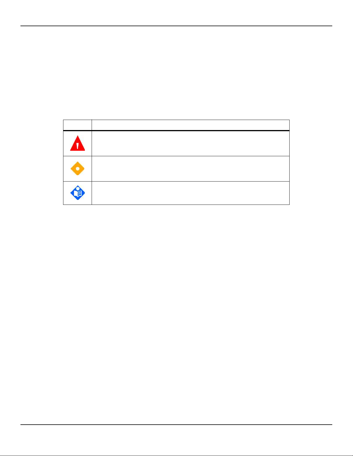
Table1-1.Safety Symbol Definitions
Symbol Definition
WARNING
Warnings alert users to potential serious outcomes (death, injury, or adverse
events) to the patient, user, or environment.
Caution
Cautions alert users to exercise appropriate care for safe and effective use of
the product.
Note
Notes provide additional guidelines or information.
1.3.2 Warnings
WARNING:
Explosion hazard — Do not use in the presence of flammable anesthetics.
WARNING:
Shock hazard — Use only when connected to a grounded outlet to avoid
electric shock.
WARNING:
Before attempting to open or disassemble, disconnect the power cord to
avoid possible injury.
WARNING:
Use only Covidien-approved internal batteries.
WARNING:
The monitoring system is not defibrillator-proof. It may remain attached to
the patient during defibrillation or during use of an electrosurgical unit,
1-2 Service Manual
Page 15

however, readings may be inaccurate during use in this environment and
shortly thereafter.
WARNING:
Supplemental oxygen will attenuate patterns of desaturation. A patient’s
respiratory compromise can be proportionally more severe before patterns
appear in the saturation trend. Remain vigilant when monitoring a patient on
supplemental oxygen.
WARNING:
Do not silence or disable audible alarms or decrease the volume of the audible
alarm if patient safety could be compromised. Do not dim or disable visual
alarms if patient safety could be compromised.
WARNING:
Ensure the monitoring system is clear of any obstructions that prevent
awareness of visual or audible alarms. Failure to do so may result in
inadvertently missing a visual alarm or an inaudible alarm tone.
Safety Information
WARNING:
Do not use any monitoring system, sensor, cable, or connector that appears
damaged. Remove any damaged equipment from service for inspection by a
qualified service technician.
WARNING:
Do not lift by the sensor or interface cable. The cable may disconnect,
potentially dropping the monitoring system on a patient or damaging
surface.
WARNING:
When installing the AC power cord, ensure the cord is carefully positioned to
prevent tripping and entanglement.
WARNING:
Do not spray, pour, or spill any liquid on the monitoring system, its accessories,
connectors, switches, or openings in the chassis, since this may cause damage
to the monitoring system.
Service Manual 1-3
Page 16

Introduction
WARNING:
WARNING:
WARNING:
1.3.3 Cautions
To ensure accurate performance and prevent device failure, do not subject to
extreme moisture, such as direct exposure to rain. Such exposure may cause
inaccurate performance or device failure.
The monitoring screen contains toxic chemicals. Do not touch a broken
enclosure or monitoring screen. Physical contact with a broken enclosure or
monitoring screen can result in transmission or ingestion of toxic substances.
No user serviceable parts inside.
Caution:
Federal law (U.S.A.) restricts this device to sale by or on the order of a
physician.
Caution:
When connecting the monitoring system to any instrument, verify proper
operation before clinical use. Both the monitoring system and the instrument
connected to it must utilize a grounded outlet. Any equipment connected to
the data interface must be certified according to the latest IEC/EN 60950 -1
standard for data-processing equipment, the latest IECEN 60601-1 standard
for electromedical equipment, or the latest IEC/EN safety standards relevant
to that equipment. All combinations of equipment must be in compliance
with Requirements for Medical Electrical Systems IEC Standard
60601-1:2007and the electromagnetic compatibility IEC/EN Standard
60601-1:2005. Anyone who connects equipment to the data interface is
configuring a medical system and, therefore, is responsible for ensuring that
the system complies with the Requirements for Medical Electrical Systems
IEC/EN Standard 60601-1-1:2007 and the electromagnetic compatibility IEC/
EN Standard 60601-1-2:2007. Accuracy may degrade if it is connected to
secondary I/O devices when the equipment is not connected to earth
reference.
1-4 Service Manual
Page 17

Caution:
Observe electrostatic discharge (ESD) precautions prior to opening the chassis
or handling any internal components.
Caution:
Observe the required torque for tightening screws. Over-tightening can strip
out screw holes, rendering them useless.
1.4 Obtaining Technical Assistance
1.4.1 Technical Services
For technical information and assistance, if unable to correct a problem while
using the monitoring system, to order parts, or to order an Operator’s or
Service Manual, contact Covidien or a local Covidien representative.
Obtaining Technical Assistance
Covidien Technical Services: Patient Monitoring
15 Hampshire Street
Mansfield, MA 02048 USA
1.800.635.5267, 1.925.463.4635 (toll)
or contact a local Covidien representative
www.covidien.com
When calling Covidien or a local Covidien representative, have the serial
number, as well as the code versions available.
To locate the serial number and code versions
1. Press MENU.
2. Press ABOUT THE MONITOR.
3. Locate the serial number under Monitor Information and code versions under
Software Information.
Service Manual 1-5
Page 18

Introduction
1.4.2 On-Screen Help
The monitoring system provides users with an on-screen help system for
various help topics. Reference To access on-screen help topics, p. 6-16.
1.5 Related Documents
Documentation is available online at www.covidien.com. Covidien makes available all appropriate information relevant to servicing monitoring system parts
designated as repairable in this manual. For further assistance, contact Covidien.
• Nellcor™ Bedside Respiratory Patient Monitoring System Operator’s
Manual — Provides basic information on operating the monitoring system and
troubleshooting errors or malfunctions. Before using the monitoring system, thoroughly read this manual.
• Nellcor™ Sensor Instructions for Use — Guides sensor selection and usage.
Before attaching any of the various Covidien-approved Nellcor™ sensors to the
monitoring system, refer to their Instructions for Use.
• Nellcor™ Oxygen Saturation Accuracy Specification Grid — Provides
sensor-specific guidance related to desired SpO2 saturation accuracy measure-
ments.
1.6 Warranty Information
To obtain information, contact Covidien or a local Covidien representative.
Purchase of this instrument confers no express or implied license under any
Covidien patent to use that instrument with any sensor not manufactured or
licensed by Covidien llc.
1-6 Service Manual
Page 19

2 Product Specifications
2.1 Overview
This chapter contains physical and operational specifications of the
Nellcor™ Bedside Respiratory Patient Monitoring System. Ensure all product
requirements are met prior to installation.
2.2 Physical Characteristics
Weight 7.5 lbs. (3.4 kg)
Dimensions 10 in. x 6.5 in. x 5 in. (252 mm x 163 mm x 122 mm)
2.3 Electrical Requirements
2.3.1 Power
Power Requirements Rated at 80-263 volts AC (nominal 120-230 VAC), 30 VA
Input Frequency 47/63 Hz
Fuses Slow-blow 1.5 amp, 250 volts, IEC (5 x 20 mm)
Quantity: 2 external
2-1
Page 20

Product Specifications
2.3.2 Battery
Note:
The battery provides approximately seven hours of battery life when new and fully-charged
with no alarms, no serial data, no analog output, no nurse call output, with backlight on
while using a pulse simulator set for 200 bpm, high light and low modulation.
Type Lithium Ion
Voltage 7.2 Volts DC, 11.6 Ah, 83 Wh
Recharge 8 hours with monitoring system turned off
Shelf Life Four months, if monitoring system runs on new, fully-charged battery
12 hours with monitoring system turned on
After four months storage, units run 33% of stated battery life
Compliance IEC 62133
2.3.3 Rating of Nurse Call Relay
Maximum Input Voltage 30 VAC or VDC (polarity is not important)
Load Current 120 mA continuous (peak 300 mA @ 100 ms)
Minimum Resistance 26.5 ohms to 50.5 ohms (40.5 ohms typical) during alarms
Ground Reference Isolated Ground
Electrical Isolation 1500 Volts
2-2 Service Manual
Page 21

2.4 Environmental Conditions
2.4.1 Operating
Temperature 5 ºC to 40 ºC (41 ºF to 104 ºF)
Altitude -304.8 m to 4,572 m
(-1,000 ft. to 15,000 ft.)
Atmospheric Pressure 105 kPa to 57.2 kPa
(31.0 in. Hg to 16.89 in. Hg)
Relative Humidity 15% to 95% non-condensing
2.4.2 Transport and Storage
Environmental Conditions
Not in shipping container In shipping container
Temperature -20 ºC to 60 ºC
(-4 ºF to 140 ºF)
Altitude -390 m to 5,574 m (-1,254 ft. to 18,288 ft.)
Atmospheric Pressure 50 kPa to 106 kPa (14.7 in. Hg to 31.3 in. Hg)
Relative Humidity 15% to 95% non-condensing
-20 ºC to 70 ºC
(-4 ºF to 158 ºF)
Service Manual 2-3
Page 22

Product Specifications
2.5 Sensor Accuracy and Ranges
This monitoring system has the capability to detect physiological alarm conditions using SpO2 accuracy, pulse rate accuracy and alarm limit conditions.
Table2-1.Nellcor™ Sensor Accuracy and Ranges
Measurement Range
SpO
2
1% to 100%
Pulse Rate 20 to 250 beats per minute (bpm)
Perfusion Range 0.03% to 20%
Accuracy
1
Saturation
2, 3
Adult
Adult and Neonate Low Sat
Neonate
Low Perfusion
4, 5
6
2, 3, 4
Adult and Neonate with Motion
2, 7
70 to 100% ±2 digits
60 to 80% ±3 digits
70 to 100% ±2 digits
70 to 100% ±2 digits
70 to 100% ±3 digits
Pulse Rate
Adult and Neonate
Low Perfusion
Adult and Neonate with Motion
1. Saturation accuracy varies by sensor type. Refer to the Nellcor™ Oxygen Saturation Accuracy Specification Grid at
www.covidien.com/rms.
2. Accuracy specifications were validated using measurements of healthy non-smoking adult volunteers during controlled
hypoxia studies spanning the specified saturation ranges. Subjects were recruited from the local population and comprised
both men and women ranging in age from 18-50 years old, and spanned a range of skin pigmentations. Pulse oximeter
SpO2 readings were compared to SaO2 values of drawn blood samples measured by hemoximetry. All accuracies are
expressed as ±1 SD. Because pulse oximeter equipment measurements are statistically distributed, about two-thirds of the
measurements can be expected to fall in this accuracy (A
3. Adult specifications are shown for OXIMAX MAX-A and MAX-N sensors with the Nellcor™ Bedside Respiratory Patient Monitoring System.
4. Neonate specifications are shown for OXIMAX MAX-N sensors with the Nellcor™ Bedside Respiratory Patient Monitoring System.
5. Clinical functionality of the MAX-N sensor has been demonstrated on a population of hospitalized neonate patients. The
observed SpO2 accuracy was 2.5% in a study of 42 patients with ages of 1 to 23 days, weight from 750 to 4,100 grams,
and 63 observations made spanning a range of 85% to 99% SaO2.
6. Specification applies to Nellcor™ Bedside Respiratory Patient Monitoring System oximeter performance. Reading accuracy
in the presence of low perfusion (detected IR pulse modulation amplitude 0.03% - 1.5%) was validated using signals
supplied by a patient simulator. SpO2 and pulse rate values were varied across the monitoring range over a range of weak
signal conditions and compared to the known true saturation and pulse rate of the input signals.
7. Motion performance was validated during a controlled hypoxia blood study. Subjects performed rubbing and tapping
movements 1-2 cm in amplitude with aperiodic intervals (randomly changing) with a random variation in frequency between
1-4 Hz. Applicability: OXIMAX MAX-A, MAX-AL, MAX-P, MAX-I, and MAX-N sensors.
2, 3, 4
6
2, 7
) range (refer to the Sensor Accuracy Grid for more details).
RMS
20 to 250 bpm ±3 digits
20 to 250 bpm ±3 digits
48 to 127 bpm ±5 digits
2-4 Service Manual
Page 23

Table2-2.Nellcor™ Sensor Operating Range and Power Dissipation
Red Light Wavelength Approximately 660 nm
Infrared Light Wavelength Approximately 900 nm
Optical Output Power Less than 15 mW
Power Dissipation 52.5 mW
2.6 Sound Pressure
Sound Pressure
Operating Range and Dissipation
Table2-3.Sound Pressure in Decibels
Volume Setting
Alarm Type
High Priority 88.1 dB 85.5 dB 80.6 dB 71.5 dB
Medium Priority 78.3 dB 75.4 dB 70.2 dB 61.2 dB
Low Priority 74.4 dB 71.1 dB 66.4 dB 57.6 dB
SPD Alarm (Low Priority) 74.4 dB 70.7 dB 65.7 dB 57.5 dB
2.7 Product Compliance
Equipment Classification IEC/EN 80601-2-61:2011
Protection Type Class I (Internally powered)
Degree of Protection Type BF - Applied part
Mode of Operation Continuous
Electromagnetic Compatibility IEC 60601-1-2:2007
High Med High Med Low Low
IEC/EN 60601-1:2005
CAN/CSA C22.2 No. 60601-1:08
ANSI AAMI ES 60601-1:2005
Liquid Ingress IPX1: Protected against harmful effects of dripping water
Degree of Safety Not suitable for use in the presence of flammable anesthetics
Service Manual 2-5
Page 24

Product Specifications
2.8 Manufacturer’s Declaration and Guidance
2.8.1 Electromagnetic Compatibility (EMC)
WARNING:
This monitoring system is intended for use by healthcare professionals only.
This monitoring system may cause radio interference or may disrupt the
operation of nearby equipment, regardless of whether it is CISPR compliant
or not. It may be necessary to take mitigation measures, such as re-orienting
or relocating the monitoring system or shielding the location.
WARNING:
The use of accessories, sensors, and cables other than those specified may
result in inaccurate readings of the monitoring system and increased EMI
emissions of the monitoring system.
The monitoring system is suitable for prescription use only in the specified electromagnetic environments, in accordance with the IEC 60601-1-2:2007 standard. The
monitoring system requires special precautions during installation and operation
for electromagnetic compatibility. In particular, the use of nearby mobile or portable communications equipment may influence monitoring system performance.
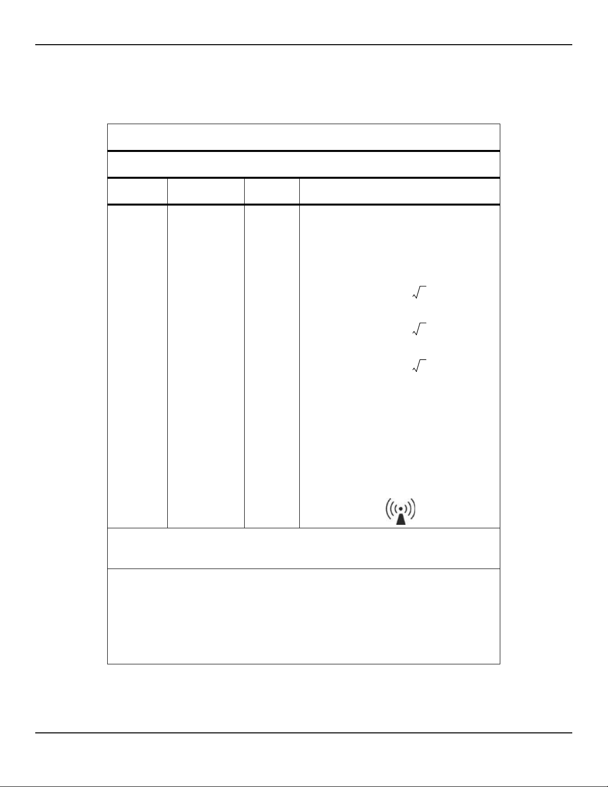
Frequency and Bandwidth for Wireless Connection
Table2-4.Frequency Band, Output Power, and Modulation Type
Frequency Band
(MHz)
2412 - 2462 0.088 BPSK, CCK, OFDM
5180 - 5240 0.018 OFDM
5260 - 5320 0.018 OFDM
5500 - 5700 0.028 OFDM
5745 - 5825 0.026 OFDM
Output Power
(Watts)
Modulation Type
2-6 Service Manual
Page 25

Manufacturer’s Declaration and Guidance
Electromagnetic Emissions
Table2-5.Electromagnetic Emissions Guidelines and Compliance
Guidance and Manufacturer’s Declaration—Electromagnetic Emissions
(IEC/EN 60601-1-2:2007, Table 1)
The monitoring system is intended for use in the electromagnetic environment specified below. The
customer or the user of the monitoring system should assure that it is used in such an environment.
Emissions Test Compliance Electromagnetic Environment Guidance
RF emission
CISPR 11
EN 55011
Harmonic emissions
IEC/EN 61000-3-2
Voltage fluctuation/
flicker emissions
IEC/EN 61000-3-3
Group 1,
Class A
Class A N/A
Complies N/A
Not intended for use in a residential environment. If
used in a domestic environment, may not offer adequate protection to radio-frequency communication
services. The user may be required to take mitigation
measures, such as relocating or re-orienting the equipment.
Service Manual 2-7
Page 26

Product Specifications
Electromagnetic Immunity
The monitoring system is intended for use in the electromagnetic environment specified below. The
customer or the user of the monitoring system should assure that it is used in such an environment.
Table2-6.Electromagnetic Immunity Guidelines and Compliance
Guidance and Manufacturer’s Declaration—Electromagnetic Immunity
(IEC/EN 60601-1-2:2007, Table 2)
Immunity
Test
Electrostatic
discharge (ESD)
IEC/EN 61000-4-2
Electric fast
transient/burst
IEC/EN 61000-4-4
Surge
IEC/EN 61000-4-5
Voltage dips, short
interruptions and
voltage variations
on power supply
IEC/EN 61000-4-11
IEC/EN 60601-1-2
Test Level
± 6 kV contact
± 8 kV air
± 2 kV for power
supply lines
± 1 kV input/
output lines
± 1 kV differential
mode
± 2 kV common
mode
<5% U
T
(>95% dip in UT)
for 0.5 cycle
40% U
(60% dip in U
T
)
T
for 5 cycles
70% U
T
(30% dip in UT)
for 25 cycles
Compliance
Level
± 6 kV contact
± 8 kV air
± 2 kV for
power supply lines
± 1 kV input/
output lines
± 1 kV differential
mode
± 2 kV common
mode
<5% U
T
(>95% dip in UT)
for 0.5 cycle
40% U
(60% dip in U
T
)
T
for 5 cycles
70% U
T
(30% dip in UT)
for 25 cycles
Electromagnetic Environment
Guidance
Floor should be wood, concrete,
or ceramic tile. If floors are
covered with synthetic material,
the relative humidity should be at
least 30%.
Mains power quality should be
that of a typical commercial and/
or hospital environment.
Mains power quality should be
that of a typical commercial and/
or hospital environment.
Mains power quality should be
that of a typical commercial and/
or hospital environment.
If the user requires continued
operation during power mains
interruption, it is recommended
that the monitoring system be
powered from an uninterruptible
power supply or battery.
Power frequency
(50/60 Hz) magnetic
field
IEC/EN 61000-4-8
Note: U
is the AC main’s voltage prior to application of the test level.
T
<5% U
T
(>95% dip in UT)
for 5 seconds
3 A/m 3 A/m It may be necessary to position
<5% U
T
(>95% dip in UT)
for 5 seconds
further from the sources of
power frequency magnetic fields
or to install magnetic shielding.
2-8 Service Manual
Page 27
Manufacturer’s Declaration and Guidance
d 1.2 P=
d 1.2 P=
d 2.3 P=
Table2-7.Recommended Separation Distance Calculations
Guidance and Manufacturer’s Declaration—Electromagnetic Immunity
(IEC/EN 60601-1-2:2007, Table 4)
The monitoring system is intended for use in the electromagnetic environment specified below. The
customer or the user of the monitoring system should assure that it is used in such an environment.
Immunity
Test
IEC/EN 60601-1-2
Test Level
Compliance
Level
Electromagnetic
Environment Guidance
Portable and mobile RF communications equipment
should be used no closer to any part of the monitoring
system, including cables, than the recommended separation distance calculated from the equation applicable to
the frequency of the transmitter.
Conducted RF
IEC/EN
61000-4-6
Radiated RF
IEC/EN
61000-4-3
3 Vrms
150 kHz to
80 MHz
3 V/m
80 MHz to
2.5 GHz
3 Vrms
150 kHz to
80 MHz
3 V/m
80 MHz to
2.5 GHz
Recommended Separation Distance
80 MHz to 800 MHz
800 MHz to 2.5 GHz
where P is the maximum output power rating of the transmitter in watts (W) according to the transmitter manufacturer and d is the recommended separation distance in
meters (m).
Field strengths from fixed RF transmitters, as determined
by an electromagnetic site survey
compliance level in each frequency range
Interference may occur in the vicinity of equipment
marked with the following symbol:
NOTE 1: At 80 MHz and 800 MHz, the higher frequency range applies.
NOTE 2: These guidelines may not apply in all situations. Electromagnetic propagation is affected by absorption and
reflection from structures, objects, and people.
a
Field strengths from fixed transmitters, such as base stations for radio (cellular/cordless) telephones and land mobile
radios, amateur radio, AM and FM radio broadcast and TV broadcast cannot be predicted theoretically with accuracy. To assess the electromagnetic environment due to fixed RF transmitters, an electromagnetic site survey should
be considered. If the measured field strength in the location in which the monitoring system is used exceeds the
applicable RF compliance level above, the monitoring system should be observed to verify normal operation. If
abnormal performance is observed, additional measures may be necessary, such as re-orienting or relocating the
monitoring system.
b
Over the frequency range 150 kHz to 80 MHz, field strengths should be less than 3 V/m.
a
, should be less than the
b
.
Service Manual 2-9
Page 28

Product Specifications
d 1.2 P=
d 1.2 P=
d 2.3 P=
Recommended Separation Distances Between Portable and Mobile RF Communications
The monitoring system is intended for use in an electromagnetic environment in which radiated RF
disturbances are controlled. The customer or the user of the monitoring system can help prevent elec-
tromagnetic interference by maintaining a minimum distance between portable and mobile RF com-
munications equipment (transmitters) and the monitoring system as recommended below, according
to the maximum output power of the communications equipment.
Table2-8.Recommended Separation Distances
Equipment and the Monitoring System
(IEC/EN 60601-1-2:2007, Table 6)
Rated Maximum
Output Power (P)
of Transmitter in
Watts
0.01 0.12 0.12 0.23
0.10 0.38 0.38 0.73
1.00 1.20 1.20 2.30
10.00 3.80 3.80 7.30
100.00 12.00 12.00 23.00
For transmitters rated at a maximum output power not listed above, the recommended separation
distance (d) in meters (m) can be estimated using the equation applicable to the frequency of the
transmitter, where P is the maximum output power rating of the transmitter in watts (W) according
to the transmitter manufacturer.
NOTE 1: At 80 MHz and 800 MHz, the separation distance for the higher frequency range applies.
NOTE 2: These guidelines may not apply in all situations. Electromagnetic propagation is affected by
absorption and reflection from structures, objects, and people.
Separation Distance According to Frequency of Transmitter in Meters
150 kHz to 80 MHz 80 MHz to 800 MHz 800 MHz to 2.5 GHz
2-10 Service Manual
Page 29

Sensor and Cable Compliance
WARNING:
The use of accessories, sensors, and cables other than those specified may
result in inaccurate readings of the monitoring system and increased emission
of the monitoring system.
Manufacturer’s Declaration and Guidance
Table2-9.Sensor and Cable Length
Item SKU Maximum Length
Sensors
Nellcor™ Adult SpO
Nellcor™ Adult XL SpO
Nellcor™ Forehead SpO
Nellcor™ Neonatal-Adult SpO
(Sterile, single-use only)
Nellcor™ Infant SpO
Nellcor™ Pediatric SpO
Nellcor™ Adult SpO
Nellcor™ Adult SpO
Nellcor™ Adult-Neonatal SpO
(Reusable with adhesive)
Nellcor™ Pediatric-Infant SpO
(Reusable with adhesive)
Nellcor™ Pediatric SpO
(Sterile, single-use only)
Nellcor™ Neonatal-Adult SpO
(Sterile, single-use only)
Nellcor™ Adult SpO
(Sterile, single-use only)
2 Sensor, Reusable (Nonsterile) DS100A 3.0 ft. (0.9 m)
2 Sensor (Sterile, single-use only) MAX-AL 3.0 ft. (0.9 m)
2 Sensor (Sterile, single-use only) MAX-FAST 2.5 ft (0.75 m)
2 Sensor (Sterile, single-use only) MAX-I
2 Sensor (Sterile, single-use only) MAX-P
2 Sensor (Sterile, single-use only) MAX-A
2 Nasal Sensor (Sterile, single-use only) MAX-R
2 Sensor, Two Piece
2 Sensor, Two Piece
2 Sensor
2 Sensor with Wraps
2 Sensor with Wraps
2 Sensor, Two Piece
MAX-N
OXI-A/N
OXI-P/I
P
N
A
1.5 ft. (0.5 m)
3.0 ft. (0.9 m)
OC-3 cable,
3.0 ft. (0.9 m)
Nellcor™ SpO
• Nellcor™ SpO2 Ear Clip, Reusable (Nonsterile) D-YSE
• Nellcor™ Pediatric SpO2 Clip, Reusable (Nonsterile) D-YSPD
Service Manual 2-11
2 Sensor, Multisite Reusable (Nonsterile) D-YS
4.0 ft. (1.2 m)
Page 30

Product Specifications
Power cord ---- 9.84 ft. (3 m)
DOC-10 interface cable 10.0 ft. (3 m)
Firmware download cable, RS-232 serial, 15 to 9 pin “D” 10.0 ft. (3 m)
Non-terminated cable, RS-232 analog, 15 pin “D” 3.3 ft. (1 m)
Printer cable, RS-232, 15 to 9 pin “D” 10.0 ft. (3 m)
Philips interface cable M1943 NL 3.3 ft. (1 m)
Oxinet™ III hardwire cable ---- 10.0 ft. (3 m)
Oxinet™ III data cable
Table2-9.Sensor and Cable Length (Continued)
Item SKU Maximum Length
Cables
2.8.2 Ground Integrity
100 milliohms or less
2.8.3 Safety Tests
The following tables describe the maximum earth and enclosure leakage
current allowed, as well as patient leakage.
Table2-10.Earth and Enclosure Leakage Current Specifications
Earth Leakage Current
Neutral
Condition AC Line Polarity Line Cord
Normal Normal Closed Closed 500 μA 300 μA
Single Fault Open Closed 1000 μA
Closed Open
Normal Reversed Closed Closed 500 μA 300 μA
Single Fault Open Closed 1000 μA
Line Cord IEC 60601-1
ANSI/AAMI
60601-1
Closed Open
2-12 Service Manual
Page 31

Manufacturer’s Declaration and Guidance
Table2-10.Earth and Enclosure Leakage Current Specifications (Continued)
Enclosure Leakage Current
Neutral
Condition AC Line Polarity
Normal Normal Closed Closed 100 μA
Single Fault Open Closed 500 μA
Normal Reversed Closed Closed 100 μA
Single Fault Open Closed 500 μA
Table2-11.Patient Applied and Patient Isolation Risk Current
Condition AC Line Polarity Neutral Line
Normal Normal Closed Closed 100 μA
Single Fault Open Closed 500 μA
Line Cord
Closed Open
Closed Open
Patient Applied Risk Current
Closed Open
Power Line
Ground
Power Line
Ground Cable
IEC 60601-1
ANSI/AAMI 60601-1
IEC 60601-1
ANSI/AAMI 60601-1
Normal Reversed Closed Closed 100 μA
Single Fault Open Closed 500 μA
Closed Open
Patient Isolation Risk Current
Power Line
Condition AC Line Polarity Neutral Line
Single Fault Normal Closed Closed 5000 μA
Reversed Closed Closed
Ground Cable
IEC 60601-1
UL 60601-1
Service Manual 2-13
Page 32

Product Specifications
Page Left Intentionally Blank
2-14 Service Manual
Page 33

3 Theory of Operations
3.1 Overview
This chapter explains the theory behind operations of the
Nellcor™ Bedside Respiratory Patient Monitoring System.
3.2 Block Diagram
The functional block diagram provides a quick, visual overview of the monitoring system.
Figure3-1.Block Diagram
3-1
Page 34

Theory of Operations
3.3 Theoretical Principles
The monitoring system uses pulse oximetry to measure functional oxygen saturation in the blood. Pulse oximetry works by applying a Nellcor™ sensor to a
pulsating arteriolar vascular bed, such as a finger or toe. The sensor contains a
dual light source and a photodetector.
Bone, tissue, pigmentation, and venous vessels normally absorb a constant
amount of light over time. The arteriolar bed normally pulsates and absorbs
variable amounts of light during the pulsations. The ratio of light absorbed is
translated into a measurement of functional oxygen saturation (SpO2).
Ambient conditions, sensor application, and patient conditions can influence
the ability of the monitoring system to accurately measure SpO2. Reference
Performance Considerations, p. 8-1.
Pulse oximetry is based on two principles: oxyhemoglobin and deoxyhemoglobin differ in their absorption of red and infrared light (measured using spectrophotometry), and the volume of arterial blood in tissue (and hence, light
absorption by that blood) changes during the pulse (registered using plethysmography). A monitoring system determines SpO2 by passing red and infrared
light into an arteriolar bed and measuring changes in light absorption during
the pulsatile cycle. Red and infrared low voltage, light-emitting diodes (LED) in
the sensor serve as light sources; a photo diode serves as the photo detector.
Since oxyhemoglobin and deoxyhemoglobin differ in light absorption, the
amount of red and infrared light absorbed by blood is related to hemoglobin
oxygen saturation.
The monitoring system uses the pulsatile nature of arterial flow to identify the
oxygen saturation of arterial hemoglobin. During systole, a new pulse of arterial blood enters the vascular bed, and blood volume and light absorption
increase. During diastole, blood volume and light absorption reach their lowest
point. The monitoring system bases its SpO2 measurements on the difference
between maximum and minimum absorption (measurements at systole and
diastole). By doing so, it focuses on light absorption by pulsatile arterial blood,
eliminating the effects of nonpulsatile absorbers such as tissue, bone, and
venous blood.
3-2 Service Manual
Page 35

3.4 Automatic Calibration
Because light absorption by hemoglobin is wavelength dependent and
because the mean wavelength of LEDs varies, a monitoring system must know
the mean wavelength of the sensor's red LED to accurately measure SpO2.
During monitoring, the monitoring system’s software selects coefficients that
are appropriate for the wavelength of that individual sensor's red LED; these
coefficients are then used to determine SpO2.
Additionally, to compensate for differences in tissue thickness, the light intensity of the sensor's LEDs is adjusted automatically.
Note:
During certain automatic calibration functions, the monitoring system may briefly
display a flat line on the plethysmographic waveform. This is a normal operation and
does not require any user intervention.
Automatic Calibration
3.5 Functional Testers and Patient Simulators
Some models of commercially available bench top functional testers and
patient simulators can be used to verify the proper functionality of Covidien
Nellcor™ monitoring systems, sensors, and cables. Reference the individual
testing device's operator's manual for the procedures specific to the model of
tester used. While such devices may be useful for verifying that the sensor,
cabling, and monitoring system are functional, they are incapable of providing
the data required to properly evaluate the accuracy of a system's SpO2 measurements.
Fully evaluating the accuracy of the SpO
mum, accommodating the wavelength characteristics of the sensor and reproducing the complex optical interaction of the sensor and the patient’s tissue.
These capabilities are beyond the scope of known bench top testers. SpO2
measurement accuracy can only be evaluated in vivo by comparing monitoring
system readings with values traceable to SaO2 measurements obtained from
simultaneously sampled arterial blood using a laboratory CO-oximeter.
Many functional testers and patient simulators have been designed to interface with the monitoring system's expected calibration curves and may be suitable for use with monitoring systems and/or sensors. Not all such devices,
however, are adapted for use with the OxiMax™ digital calibration system.
2 measurements requires, at a mini-
Service Manual 3-3
Page 36

Theory of Operations
100 +–
---------------------------------
100=
While this will not affect use of the simulator for verifying system functionality,
displayed SpO2 measurement values may differ from the setting of the test
device. For a properly functioning monitoring system, this difference will be
reproducible over time and from monitoring system to monitoring system
within the performance specifications of the test device.
3.6 Unique Technologies
3.6.1 Functional versus Fractional Saturation
This monitoring system measures functional saturation where oxygenated
hemoglobin is expressed as a percentage of the hemoglobin that can transport
oxygen. It does not detect significant amounts of dysfunctional hemoglobin,
such as carboxyhemoglobin or methemoglobin. In contrast, hemoximeters
such as the IL482, report fractional saturation where oxygenated hemoglobin
is expressed as a percentage of all measured hemoglobin, including measured
dysfunctional hemoglobins. To compare functional saturation measurements
to those from a monitoring system that measures fractional saturation, fractional measurements must be converted using the listed equation.
functional saturation %carboxyhemoglobin
fractional saturation %methemoglobin
3.6.2 Measured versus Calculated Saturation
When calculating saturation from a blood gas partial pressure of oxygen (PO2),
the calculated value may differ from the SpO
2 measurement of a monitoring
system. This usually occurs when saturation calculations exclude corrections
for the effects of variables such as pH, temperature, the partial pressure of
carbon dioxide (PCO2), and 2,3-DPG, that shift the relationship between PO2
and SpO
3-4 Service Manual
2.
Page 37

Figure3-2.Oxyhemoglobin Dissociation Curve
Unique Technologies
1 % Saturation Axis 3 Increased pH; Decreased temperature, PCO2, and 2,3-DPG
2 PO2 (mmHg) Axis 4 Decreased pH; Increased temperature, PCO2, and 2,3-DPG
Data Update Period, Data Averaging, and Signal Processing
3.6.3
The advanced signal processing of the OxiMax™ algorithm automatically extends
2
the amount of data required for measuring SpO
and pulse rate depending on the
measurement conditions. The OxiMax™ algorithm automatically extends the
dynamic averaging time required beyond seven (7) seconds during degraded or difficult measurement conditions caused by low perfusion, signal artifact, ambient
light, electrocautery, other interference, or a combination of these factors, which
results in an increase in the dynamic averaging. If the resulting dynamic averaging
time exceeds 20 seconds for SpO2, the monitoring system displays the pulse search
indicator while continuing to update SpO2 and pulse rate values every second. If
the dynamic averaging time exceeds 25 seconds, a low-priority Extended Update
alarm also appears.
As such measurement conditions extend, the amount of data required may
continue to increase. If the dynamic averaging time reaches 40 seconds, and/
or 50 seconds for pulse rate, a high priority alarm state results: the monitoring
Service Manual 3-5
Page 38

Theory of Operations
system displays the Pulse Timeout alarm and reports a zero saturation indicating a loss-of-pulse condition.
3.7 System Features
3.7.1 Nellcor™ Sensor Technology
Use Nellcor™ sensors, which are specifically designed for use with the monitoring system. Identify Nellcor™ sensors by the Nellcor™ logo on the plug. All
Nellcor™ sensors contain a memory chip carrying information about the
sensor which the monitoring system needs for correct operation, including the
sensor’s calibration data, model type, troubleshooting codes, and error detection data.
This unique oximetry architecture enables several new features. When a Nellcor™ sensor is connected to the monitoring system, the monitoring system
reads the information from the sensor memory chip, ensures it is error free,
and then loads the sensor data prior to monitoring for new information. As the
monitoring system reads sensor information, it sends the sensor model
number to the monitoring screen. This process may take a few seconds. The
sensor model number disappears after the monitoring system starts tracking
the patient’s SpO2 and pulse rate.
Any monitoring system containing OxiMax technology uses calibration data
contained in the sensor in calculating the patient’s SpO2. With sensor calibration, the accuracy of many sensors is improved, since the calibration coefficients can be tailored to each sensor.
Contact Covidien or a local Covidien representative for a Nellcor™ Oxygen Sat-
uration Accuracy Specification Grid listing all of the sensors used with the monitoring system. Covidien retains a soft copy at www.covidien.com
.
The monitoring system uses the information in the sensor, tailoring messages
to better help the clinician troubleshoot client or data issues. The sensor automatically identifies its sensor type to the monitoring system when attached.
3-6 Service Manual
Page 39

3.7.2 SatSeconds™ Alarm Management Parameter
The monitoring system monitors the percentage of hemoglobin binding sites
saturated with oxygen in the blood. With traditional alarm management, upper
and lower alarm limits are set to alarm at specific SpO
2
levels. When the SpO2
level fluctuates near an alarm limit, the alarm sounds each time it violates the
alarm threshold. SatSeconds monitors both degree and duration of desaturation
as an index of desaturation severity. Thus, the SatSeconds parameter helps distinguish clinically significant events from minor and brief desaturations that may
result in nuisance alarms.
Consider a series of events leading to a violation of the SatSeconds alarm limit.
An adult patient experiences several minor desaturations, then a clinically significant desaturation.
Figure3-3.Series of SpO2 Events
System Features
a First SpO
b Second SpO
cThird SpO
Service Manual 3-7
2 Event
2 Event
2 Event
Page 40

Theory of Operations
First SpO2 Event
Consider the first event. Suppose the SatSeconds alarm limit is set to 25. The
patient’s SpO2 drops to 79% and the duration of the event is two (2) seconds
before saturation again exceeds the lower alarm threshold of 85%.
Because the SatSeconds alarm limit is set to 25 and the actual number of
SatSeconds equals 12, there is no audible alarm.
6% drop below the lower alarm limit threshold
x 2 second duration below the lower threshold
12 SatSeconds; no alarm
Figure3-4.First SpO2 Event: No SatSeconds Alarm
3-8 Service Manual
Page 41

Second SpO2 Event
Consider the second event. Suppose the SatSeconds alarm limit is still set to
25. The patient’s SpO2 drops to 84% and the duration of the event is 15
seconds before saturation again exceeds the lower alarm threshold of 85%.
1% drop below the lower alarm limit threshold
x15 second duration below the lower threshold
15 SatSeconds; no alarm
Because the SatSeconds alarm limit is set to 25 and the actual number of
SatSeconds equals 15, there is no audible alarm.
Figure3-5.Second SpO2 Event: No SatSeconds Alarm
System Features
Service Manual 3-9
Page 42

Theory of Operations
Third SpO2 Event
Consider the third event. Suppose the SatSeconds alarm limit is still set to 25.
During this event, the patient’s SpO2 drops to 75%, which is 10% below the
lower alarm threshold of 85%. Since the patient’s saturation does not return
to a value over the lower alarm threshold within 2.5 seconds, an alarm sounds.
At this level of saturation, the event cannot exceed 2.5 seconds without invoking a SatSeconds alarm.
10% drop below the lower alarm limit threshold
x2.5 second duration below the lower threshold
25 SatSeconds; results in an alarm
Figure3-6.Third SpO2 Event: Triggers SatSeconds Alarm
3-10 Service Manual
Page 43

The SatSeconds Safety Net
The SatSeconds “Safety Net” is for patients with saturation levels frequently
below the limit, but not staying below the limit long enough for the SatSeconds time setting to be reached. When three or more limit violations occur
within 60 seconds, an alarm sounds even if the SatSeconds time setting has
not been reached.
3.7.3 OxiMax SPD™ Alert Parameter
WARNING:
Supplemental oxygen will attenuate patterns of desaturation. A patient’s
respiratory compromise can be proportionally more severe before patterns
appear in the saturation trend. Remain vigilant when monitoring a patient on
supplemental oxygen.
System Features
Caution:
Do not modify any other alarm settings while using the SPD parameter.
The OxiMax SPD™ Alert (SPD) method of detecting patterns of desaturation in
adults is a function of the software within the monitoring system, which
detects repetitive occurrences of desaturation followed by resaturation. These
patterns are indicative of repetitive reductions in airflow through the upper
airway and into the lungs. With the SPD parameter enabled, the default value
for SatSeconds alarms is 100.
Service Manual 3-11
Page 44

Theory of Operations
The SPD parameter detects patterns of desaturation in adults that are indicative of
repetitive reductions in airflow through a patient's upper airway into the lungs. Relative reductions in a patient's minute ventilation over a period of time may cause
a progressive drop in alveolar partial pressure of oxygen, leading to arterial desaturation. If these decreases in ventilation are repetitive, they generate distinct patterns in the saturation trend. Patterns of repetitive desaturation often develop
gradually over time, increasing in severity. Detection of patterns indicates that a
patient might be suffering progressively severe decrements in airflow that may
increase in acuity if left untreated.
Figure3-7.Clinically Significant Desaturation Patterns
Patterns of desaturation are multiple, sequential occurrences of a desaturation
followed by a resaturation. The SPD parameter qualifies patterns of desaturation resulting from such repetitive reductions in airflow based on specific characteristics.
The SPD parameter qualifies these patterns of desaturation over a period of six
(6) minutes. Depending on the sensitivity setting for SPD, patterns that persist
may result in an SPD alarm, alerting the caregiver to the condition.
• The severity of the desaturation event (the depth of the desaturation during the
event) and the extent of the following resaturation
• The regularity of the desaturation events (how often the pattern repeats)
• The slope of the desaturation/resaturation trends that form the events
The SPD parameter communicates information to the caregiver about these
patterns of desaturation in a variety of ways with icons and alarms and in trend
data.
3-12 Service Manual
Page 45

When the indicator reaches capacity, indicating the SPD limit has been
reached, an audible alarm sounds and an alarm warning flashes. The default
setting of one (1) is the most sensitive to desaturation patterns and results in
more frequent alarms. For less frequent alarms, use a less sensitive setting of
two (2) or three (3).
Note:
Unrecognized repetitive reductions in airflow through the upper airway occur in some
clinically significant scenarios. Patients exhibiting sleep apnea symptoms were used in
studies to validate the SPD™ Alert parameter. The presence of repetitive reductions
in airflow was scored using a standard diagnostic polysomnogram. Study results
indicate SPD is a sensitive marker in detecting repetitive reductions in airflow.
3.7.4 Pulse Rate Delay Alarm Management Parameter
System Features
The monitoring system also monitors pulse rate by determining the number of
pleth waves over unit time. With traditional alarm management, upper and
lower alarm limits are set for monitoring pulse rate. When pulse rates fluctuate
near an alarm limit, alarms trigger with each violation. Pulse Rate Delay allows
a period of threshold violation before the pulse rate alarm sounds. Thus, it distinguishes clinically significant events from minor and brief pulse rate limit violations that result in nuisance alarms.
To use Pulse Rate Delay, set the traditional alarm management upper and
lower pulse rate alarm limits. Then, set Pulse Rate Delay. The Pulse Rate Delay
limit controls the time the pulse rate level crosses either limit before an audible
alarm sounds.
Service Manual 3-13
Page 46

Theory of Operations
Page Left Intentionally Blank
3-14 Service Manual
Page 47

4 Product Overview
4.1 Overview
This chapter contains basic introductory information for operating the
Nellcor™ Bedside Respiratory Patient Monitoring System. The monitoring
system relies on unique oximetry technology and design in providing hospitals,
clinicians and caregivers accurate, timely data.
4.2 Product Description
The Nellcor™ Bedside Respiratory Patient Monitoring System provides continuous noninvasive monitoring of functional oxygen saturation of arterial hemoglobin SpO2 and pulse rate.
4.3 Indications for Use
The Nellcor™ Bedside Respiratory Patient Monitoring System is a portable
pulse oximeter intended for prescription use only as a continuous non-invasive
monitor of arterial oxygen saturation (SpO2) and pulse rate of adult, pediatric,
and neonatal patients during both no motion and motion conditions, and for
patients who are well or poorly perfused. The monitoring system is intended
for use in hospitals, hospital-type facilities, and during intra-hospital transport.
The OxiMax SPD™ Alert (SPD) feature is intended only for facility-use care of
adults to detect patterns of desaturation indicative of repetitive reductions in
airflow through the upper airway and into the lungs.
Note:
• Hospital use typically covers such areas as general care floors (GCFs), operating
rooms, special procedure areas, intensive and critical care areas within the hospital
and in hospital-type facilities. Hospital-type facilities include physician office-based
facilities, sleep labs, skilled nursing facilities, surgicenters, and sub-acute centers.
• Intra-hospital transport includes transport of a patient within the hospital or hos-
pital-type facility.
4-1
Page 48

Product Overview
Use with any particular patient requires the selection of an appropriate Nellcor™ sensor.
Monitoring system users can access trend information, change alarm limits,
adjust the internal time clock, select the communications protocol, and choose
alternative interface languages.
The monitoring system operates on AC power or on an internal battery.
4.4 List of Components
The typical monitoring system carton ships with the following contents.
Table4-1.Typical Packing List
Quantity Item
1 Nellcor™ Bedside Respiratory Patient Monitoring System
1 DOC-10 interface cable
1 Operator’s Manual (applicable to country of sale) and/or compact disc
1 Hospital-grade power cord (applicable to country of sale)
4.5 Synopsis
Caregivers may use the monitoring system by connecting it to an interface
cable and a Nellcor™ sensor, then attaching the recommended sensor to a
patient. When the monitoring system detects a valid pulse, it enters monitoring
mode and displays patient parameters.
The movement of the blip bar or the plethysmographic waveform and the
flashing heart icon are visual indicators of real-time data. The pulse beep
tone is an audible indicator of the real-time patient data.
If the monitoring system detects an alarm condition, it provides both visual and
audible alarms. Reference Alarms and Error Conditions, p. 11-4, for alarm conditions.
After monitoring is no complete, remove the recommended sensor from the
patient.
4-2 Service Manual
Page 49

4.6 Product Views
4.6.1 Front Panel
Product Views
Figure4-1.Front Panel
1 Power on key Powers on and off 6 Type BF Indicates Type BF
applied part
2 AC indicator Indicates connection
to alternating current
power source
3 Battery condition
indicator
4 --- Speaker Issues audible alarms 9 Universal
5 --- Sensor port Houses interface
Service Manual 4-3
Indicates battery is
charging
cable connector
7 Data port Houses DB-15 serial
connector
8 Ethernet port Houses RJ-45 ethernet
receptacle
Houses USB connector
Serial Bus port
10 --- Parameter
module
(front)
Offers monitoring system
modular customization
Page 50

Product Overview
4.6.2 Monitoring Screen
Figure4-2.Sample Monitoring Screen Elements
1 --- Monitor status field Contains patient information in various forms.
2 --- Alarm status field Contains prioritized alarms or user prompts.
3 --- Trend data type
Contains types of graphed trend data included.
button
4 Plethysmographic
waveform
This non-normalized waveform uses real-time sensor signals,
reflecting relative pulsatile strength.
5 --- Trend data time scale Contains time period for graphed trend data. Press “-” or “+” to
change the time period.
6 Battery fuel gauge Indicates remaining battery charge and lists percentage of total
charge remaining. Fill color indicates acceptable, low, or at a critical state of charge. Lightning bolt indicates monitoring system is
connected to AC and charging if not fully charged.
7 Fast response mode
Icon
Indicates algorithm response to SpO
seconds.
2 data changes in two to four
8 --- Date and time field Reflects current date and time.
4-4 Service Manual
Page 51

Product Views
9 Baby icon (Neonate
Mode)
10 Audio alarm paused/
off icon
11 SatSeconds™ icon &
limit value
12 SpO2 upper and lower
limits
13 Dynamic %SpO2 value Indicates SpO2 saturation levels. Cyan SpO2 values zero during
14 SPD icon & sensitivity
value
15 Pulse rate (BPM) upper
and lower limits
16 Pulse rate (BPM) real-
time value
Indicates alarm limits are set to neonate limit values, not set to
adult limit values.
Yellow alarm silenced icon indicates Alarm Audio Paused or
volume set to zero. Red icon indicates Alarm Audio OFF.
Fills in the clockwise direction with saturation readings outside
limits and empties counterclockwise when within SpO2 limits.
When completely full, it alarms.
Displays current upper and lower alarm limit settings to the right
of the dynamic SpO2 value.
loss-of-pulse conditions. Updates continue during Pulse Search.
Fills from bottom to top as patterns of desaturation in the SpO2
trend become more severe and empties from top to bottom as the
patterns become less severe. If the icon fills completely, an alarm
sounds.
Displays current upper and lower alarm limit settings to the right
of the dynamic pulse rate value.
Indicates pulse rate in beats per minute. Green pulse rate values
zero during loss-of-pulse conditions.
17 Lock bar icon Provides option of locking out all response to monitoring screen
contact except the lock bar.
18 Interference indicator Lights when incoming signal is inadequate or degraded. Reference
Performance Considerations, p. 8-1.
19 Pulse search indicator Flashes during pulse search or lights continuously during loss-of-
pulse conditions.
20 Help information icon Provides access to on-screen help. Press for descriptions and sug-
gestions.
21 Trend data graph Contains patient trend data dictated by trend data type and trend
data time scale.
22 Menu selection icon Provides access to menus. Press to alter alarm limits, patient trend
data history, screen selections, connectivity settings, as well as
audio and visual control.
Service Manual 4-5
Page 52

Product Overview
23 Silence alarm icon Normally a white icon on grey background. Lights continuously as
a yellow icon on grey background with silenced audible alarm,
and as a disabled grey icon on grey background when audible
alarms are disabled. Silence duration (not shown) counts down on
screen.
-- Pulse amplitude (blip
bar)
-- Pulse beat (heart) icon (Not shown in figure.) Flashes to indicate each real-time pulse
4.6.3 Rear Panel
(Not shown in figure.) Indicates pulse beat and the relative (nonnormalized) pulse amplitude in numbers only view. As the detected pulse becomes stronger, more bars light with each pulse.
beat.
Figure4-3.Rear Panel
1 Equipotential terminal (Ground) 4 Carrying handle
2 AC power connector 5 Screw hole for adapter plate (4x)
3 Fuse drawer 6 Internal battery access
7 Parameter module (rear)
4-6 Service Manual
Page 53

4.7 Labeling Symbology
Table4-2.Labeling Symbols and Descriptions
Symbol Description Symbol Description
Must consult instructions for use Date of manufacture
Labeling Symbology
Caution, consult accompanying documents
Equipotential terminal (ground) Type BF applied part -
Fuse replacement: 1.5 amp Federal Communications Commission:
Protection against fluid ingress This side up
Atmospheric pressure limitations Keep dry
Temperature limitations Fragile
Humidity limitations Do not use during magnetic resonance
Electromagnetic interference may
occur in the vicinity of equipment
marked with this symbol
European Community (EC) authorized
representative
Proper waste disposal for electrical and
electronic equipment
Not defibrillator proof
Compliance with FCC
imaging
Catalog number
CSA – Canadian Standards Association
certification mark
CE – Conformité Européene authorization mark
0123 – TÜV SÜD Product Service
GmbH (notified body)
Australian wireless compliance mark Consult instructions for use
Service Manual 4-7
Prescription only
Page 54

Product Overview
Page Left Intentionally Blank
4-8 Service Manual
Page 55

5 Installation
5.1 Overview
This chapter contains information for the installation and set up of the
Nellcor™ Bedside Respiratory Patient Monitoring System, prior to first-time
usage by the clinician. Before operating the monitoring system, thoroughly
read the Operator's Manual.
Inspect the monitoring system for mechanical and functional damage or deterioration prior to every use. Do not use if it appears damaged or does not
perform as expected. Have a qualified service technician install and set up the
monitoring system after performing functional tests per the Service Manual.
5.2 Safety Reminders
WARNING:
Explosion hazard — Do not use the monitoring system in the presence of
flammable anesthetics.
WARNING:
Use the test data sheet to ensure the monitoring system passes all safety,
performance, and functional tests prior to use in a clinical setting.
WARNING:
To ensure patient safety, do not place the monitoring system in any position
where it might tip or fall on the patient. Do not allow direct contact with the
patient.
WARNING:
As with all medical equipment, carefully route patient cabling to reduce the
possibility of patient entanglement or strangulation.
5-1
Page 56

Installation
WARNING:
WARNING:
WARNING:
Disconnect the monitoring system and sensor from the patient during
magnetic resonance imaging (MRI) scanning. Objects containing metal can
become dangerous projectiles when subjected to the strong magnetic fields
created by MRI equipment. Also, induced currents could potentially cause
burns.
To ensure accurate performance and prevent device failure, do not subject
the monitoring system to extreme moisture, such as direct exposure to rain.
Such exposure may cause inaccurate performance or device failure.
Do not connect the monitoring system to an electrical outlet controlled by a
wall switch, since this increases the risk of removal of AC power to the
monitoring system.
WARNING:
Use only Covidien-approved sensors and interface cables when connecting to
the sensor connector. Connecting any other cable or sensor influences the
accuracy of sensor data, which may lead to adverse results.
WARNING:
Use only Covidien-approved interface cables with the monitoring system. Use
of another interface cable will adversely impact performance. Do not attach
any cable intended for computer use to the sensor port.
WARNING:
The monitoring system should not be used adjacent to or stacked with other
equipment. If adjacent or stacked use is necessary, observe the monitoring
system to verify normal operation in the desired configuration.
WARNING:
Ensure the monitoring system is clear of any obstructions that prevent
awareness of visual or audible alarms. Failure to do so may result in
inadvertently missing a visual alarm or an inaudible alarm tone.
5-2 Service Manual
Page 57

WARNING:
Do not lift the monitoring system by the interface cable or power cord. The
cable or cord may disconnect, potentially dropping the monitoring system on
a patient or a damaging surface.
Note:
The monitoring system incorporates watchdog timers that reset the monitoring
system in the event of software errors. Any temporary limit settings are retained in the
event of a watchdog reset.
5.3 Product Setup
The monitoring system receives power either from an AC connection
(80-263 VAC) or from a 7.2-volt, 11.6 ampere-hour battery. The monitoring
system internal battery can be used to power the monitoring system during
transport or when AC power is not available. The monitoring system communicates the transition from AC power to battery power or from battery power
to AC power via the AC power or battery indicator on the front panel.
Product Setup
A new, fully charged battery provides approximately six hours of monitoring
time under typical conditions.
5.3.1 Mounting Options and Transport Considerations
Users may choose from a variety of mounting configurations, including
adapter plates, wall mounts, and pole mounts. Follow the installation instructions included with the mounting hardware.
Prior to intra-hospital transport, ensure the monitoring system interface is
locked to avoid any inadvertent changes.
5.3.2 Connection to an AC Power Source
WARNING:
Do not connect the monitoring system to an electrical outlet controlled by a
wall switch, since this increases the risk of removal of AC power to the
monitoring system.
Service Manual 5-3
Page 58

Installation
Caution:
Caution:
Caution:
Use only a hospital-grade power cord.
Ensure the monitoring system is properly grounded when operating on AC
power. If uncertain whether the AC outlet is properly grounded, disconnect
the monitoring system from the outlet and use battery power. Contact a
qualified electrician to examine the outlet for ground connections.
Do not block cooling vents.
Ensure the monitoring system remains connected to an AC power source
when not in use so a fully charged battery remains available for use at any time.
To connect to an AC power source
1. Plug the female connector end of the power cord into the power connector on
the rear of the monitoring system. Reference Rear Panel, p. 4-6.
2. Plug the male connector of the power cord into a properly grounded AC outlet.
3. Verify the monitoring system’s AC power indicator lights.
Note:
If the AC power indicator does not light, check the power cord, user-accessible fuses,
and AC power outlet.
5.3.3 Battery Insertion
WARNING:
Install only Covidien-approved batteries.
The monitoring system ships with a separate internal battery. The battery must
be installed prior to use in a clinical setting. Reference Battery or Battery Access
Door Replacement, p. 12-7. Insert the battery and test the monitoring system
prior to use in a clinical setting. Users should immediately and completely
charge the battery prior to clinical use or temporary storage of the battery.
Users should also remain vigilant when running on battery power and reconnect to AC power during a low battery state.
5-4 Service Manual
Page 59

5.3.4 Battery Charge
WARNING:
Charge only with specified charger, according to instructions. Do not heat
above 80 ºC. Do not open battery, dispose of in fire, or short circuit. It may
ignite, explode, leak, or get hot, causing personal injury.
Caution:
To fully recharge a low or fully-depleted battery, connect the monitoring
system to an AC power outlet. Charge the battery for at least eight hours with
the monitoring system turned off or twelve hours with the monitoring
system turned on. Have a qualified service technician periodically check the
battery; if fewer than four bars light after fully charging the battery, the
technician should replace the battery. Recharge the battery at least every
three months, allowing the full charge time if it is the first recharge in several
weeks.
Product Setup
Note:
Whenever the monitoring system is connected to AC power, the battery is charging.
Excessive temperatures will cause battery cell failure. Continued excessive temperatures may trigger the thermal fuse, which permanently shuts down the
battery. Should this occur, replace the battery pack.
To fully charge the battery
1. Connect the monitoring system to AC power. The monitoring system will not
power up without connection to AC power when the battery charge is below 4%.
2. Verify the monitoring system is off and the AC Power/Battery Charging indicator
lights. On AC power up, check the battery fuel gauge. If the gauge is empty or
only partially full, the battery begins charging. The monitoring system operates on
AC power while the battery is charging. When the monitoring system is fully
charged, the green battery fuel gauge registers 100%. Note that when the monitoring system is connected to AC, a lightning bolt appears in the battery fuel
gauge.
3. Until the battery recharges, the monitoring system displays the message, BATTERY
CRITICALLY LOW and supplies the additional information: THE MONITOR’S
BATTERY IS CRITICALLY LOW. THE MONITOR MAY SHUT DOWN IF AC POWER IS
LOST. DO NOT DISCONNECT MONITOR FROM AC POWER SOURCE. If AC power
is lost before the battery is charged past the critically low state, the monitoring
Service Manual 5-5
Page 60

Installation
WARNING:
Caution:
system will not produce a low battery alarm for the standard CRITICALLY LOW
BATTERY warning duration.
5.3.5 Battery Power Usage
Do not use monitoring system in a depleted battery condition.
Should a low battery alarm sound, connect the monitoring system to an AC
power source and then silence the alarm by pressing ALARM SILENCE. If the
monitoring system is operated on an AC power source with a depleted
battery and AC power is subsequently lost, the monitoring system will shut
down immediately.
The monitoring system will operate on battery when not connected to AC
power. Some usage conditions draw more power from the internal battery
than others. Duration of operation depends on the battery charge status.
Avoid power-intensive conditions for ideal battery usage. The following conditions will help achieve the longest battery life:
• No audible alarms sound
• No analog or serial output devices are attached to the monitoring system, includ-
ing serial data, analog output, and nurse call output
• 25% monitoring screen brightness setting
Ensure the monitoring system remains connected to an AC power source
when not in use so a fully charged battery remains available for use at any time.
When any of the following conditions are present, the monitoring system
automatically shuts down.
• The monitoring system is running on battery power and the battery capacity
remaining reaches 0%.
•
The monitoring system has detected an internal temperature above 67 ºC or 153 ºF.
5-6 Service Manual
Page 61

5.4 Connection to Nellcor™ Sensors
WARNING:
Use only Covidien-approved sensors and interface cables when connecting to
the sensor port. Connecting any other cable or sensor influences the accuracy
of sensor data, which may lead to adverse results.
The top of the monitoring system screen indicates the sensor type when connecting a recommended sensor to the monitoring system or when the monitoring system completes POST with an attached sensor.
Note:
Physiological conditions such as excessive patient movement, medical procedures, or
external agents such as dysfunctional hemoglobin, arterial dyes, low perfusion, dark
pigment, and externally applied coloring agents such as nail polish, dye, or pigmented
cream may interfere with the monitoring system’s ability to detect and display
measurements.
Connection to Nellcor™ Sensors
Note:
Sensor LED light emissions fall within Class 1 level, according to IEC 60825-1:2001.
To fully connect a Nellcor™ sensor
1. Firmly connect a Nellcor™ interface cable to the monitoring system’s sensor port.
Reference Front Panel, p. 4-3, to identify the port.
2. Open the plastic latch at the other end of the interface cable.
3. Plug the interface cable and recommended sensor together.
4. Snap the plastic latch down over the connectors.
Figure5-1.Sensor Cable insertion into Interface Cable
Service Manual 5-7
Page 62

Installation
5. Apply the recommended sensor to the patient after reading the Instructions for
Use accompanying the sensor.
6. When the monitoring system detects a valid pulse, it enters the monitoring mode
and displays real-time patient data.
7. Detach the recommended sensor from the patient on completion of monitoring.
5-8 Service Manual
Page 63

6 Operation
6.1 Overview
This chapter identifies methods for collecting patient oxygen saturation data
while using the Nellcor™ Bedside Respiratory Patient Monitoring System. It
describes menu navigation, power on/off and monitoring screen options,
parameter ranges, Nellcor™ sensor attachments, and configuring default settings suitable for the specific care environment.
Perform regular maintenance and safety checks every 24 months. In the case
of mechanical or functional damage, contact Covidien or a local Covidien representative.
6.2 Power
WARNING:
Explosion hazard — Do not use the monitoring system in the presence of
flammable anesthetics.
Caution:
Replace the internal battery every 24 months.
Caution:
Remove and store the internal battery if users expect a significant period of
disuse.
Caution:
A normal power cycle or complete discharge of the battery results in a reset
of all temporary user settings to factory or institutional default settings.
6-1
Page 64

Operation
6.2.1 AC Power
When the user connects the monitoring system to an AC power source, if the
internal battery requires charging, the battery condition indicator on the front
panel lights until the internal battery reaches complete charge. In addition,
when the monitoring system is powered on, the battery fuel gauge on the
monitoring screen displays a lightning bolt indicating connection to AC.
If the user powers off the monitoring system while the internal battery is
charging, the battery condition indicator remains lit and the internal fan turns
on until charging completes. Reference Connection to an AC Power Source, p.
5-3.
6.2.2 Battery Power
WARNING:
Do not use monitoring system with a depleted battery or in a low voltage
condition.
Battery Status
Reference Battery Power Usage, p. 5-6, for details on initial internal battery
setup information.
The yellow BATTERY LOW warning flashes and a medium priority alarm sounds
when approximately 14% capacity remains on the existing battery charge. The
red BATTERY CRITICALLY LOW warning flashes and a high priority alarm
sounds when approximately 4% capacity remains on the existing battery
charge. The battery will drain completely and the monitoring system will shut
down if not connected to AC power during a critically low battery condition.
Reference Battery Power Status, p. 6-3, for a description of the low and critical
battery conditions.
To cancel a visual or audible battery condition alarm, connect the monitoring
system to an AC power source. The low battery warning status remains as long
as the battery is in a low voltage condition or until the caregiver presses
DISMISS ALARM for the low battery alarm message.
6-2 Service Manual
Page 65

Battery Fuel Gauge
Caution:
Should a low battery alarm sound, connect the monitoring system to an AC
power source and then silence the alarm by pressing ALARM SILENCE. If the
monitoring system is operated on an AC power source with a depleted
battery and AC power is subsequently lost, the monitoring system will shut
down immediately.
The monitoring system runs on an internal battery when not connected to an
AC power source. A battery fuel gauge displays the remaining battery power.
When connected to AC power, the battery fuel gauge displays a lightning bolt
while charging and at full charge.
Power
Reference
p. 5-6.
Note:
The battery is recyclable. Do not dispose of the battery by placing it in the regular
trash. Dispose of the battery in accordance with local guidelines and regulations or
contact Covidien to arrange for disposal.
Note:
As the battery is used and recharged over time, the amount of time between the onset
of low battery alarms and the monitoring system shut-off may become shorter.
None Green Normal Status — Indicates 15-100% (approximately 15
BATTERY LOW Yellow Low Status — Indicates 5-14% (approximately 15 minutes)
BATTERY CRITICALLY
LOW
Connection to an AC Power Source
Table6-1.Battery Power Status
Message Color Power Charge Status
minutes to 6 hours) battery capacity remains.
battery capacity remains.
Red Critical Status — Indicates 1-4% (approximately 5 minutes)
battery capacity remains.
, p. 5-3. Reference
1
Battery Power Usage
,
1. The levels listed are based on a new battery. Continued battery charge and discharge eventually reduces capacity. For
example, a battery two years old may provide only 75% of the capacity of a new battery.
Service Manual 6-3
Page 66

Operation
6.2.3 Power Up
Power Prerequisites
Caution:
If any pixel in the monitoring screen does not light at power up, do not use
the monitoring system.
Caution:
During POST (immediately after power-up), confirm that all pixels in the
monitoring screen turn on and the monitoring system speaker sounds a
sequence of three ascending tones. After the POST process completes,
confirm that a single one-second tone sounds.
Before using the monitoring system in a clinical setting, ensure the monitoring
system is safe and working properly. Verify proper working condition at each
power up by following the directions for powering up the monitoring system.
To do so, carefully view the splash screen during power on. Verify there are no
black gaps on the monitoring screen during power-on self-test (POST) or when
every pixel on the screen is completely lit. Should users observe any black gaps
or unlit pixels, do not use the monitoring system before having the monitoring
system serviced.
Power-on Self-Test (POST)
WARNING:
Use the test data sheet to ensure the monitoring system passes all safety,
performance, and functional tests prior to use in a clinical setting.
WARNING:
Ensure the monitoring system is clear of any obstructions that prevent
awareness of visual or audible alarms. Failure to do so may result in
inadvertently missing a visual alarm or an inaudible alarm tone.
WARNING:
If the power-on self-test (POST) pass tone does not sound, do not use the
monitoring system. Instead, contact Covidien or a local Covidien
representative.
6-4 Service Manual
Page 67

WARNING:
Power-up performance tests verify both power-on self-test (POST) and
power-on defaults and alarm range limits.
At power on, the monitoring system performs a power-on self-test (POST), which
tests the circuitry and functions, then proceeds to the default monitoring screen.
Attach a sensor cable and a recommended sensor and the monitoring system is
ready to register and record patient trend data. Reference
Sensors
, p. 5-7.
Note:
Physiological conditions such as excessive patient movement, medical procedures, or
external agents such as dysfunctional hemoglobin, arterial dyes, low perfusion, dark
pigment, and externally applied coloring agents such as nail polish, dye, or pigmented
cream may interfere with the monitoring system’s ability to detect and display
measurements.
Power
Connection to Nellcor™
Note:
In addition to serving as the POST pass verification, the POST pass tone also functions
as an audible confirmation that the speaker is performing properly. If the speaker does
not function, the alarm warning sounds cannot be heard.
Note:
For standard usage, connect sensor cables prior to turning on the monitoring system.
Have a qualified service technician perform any functional testing prior to usage.
To power up the monitoring system
1. Connect the monitoring system to an AC power source.
2. Verify the monitoring system is off and the AC Power Indicator lights.
3. Turn on the monitoring system by pressing the POWER ON key.
4. Within ten seconds, all pixels should illuminate. The monitoring screen should
display a corporate logo and the firmware version of the monitoring system.
5. Observe the monitoring screen for the POST splash screen, which appears for
approximately five (5) seconds.
6. Listen for three ascending tones then a one-second beep, indicating proper oper-
ation of the speaker and successful completion of power-on self-test.
Service Manual 6-5
Page 68

Operation
Figure6-1.Sample POST Splash Screen
If the monitoring system detects an internal problem during the POST process,
an error tone sounds and the monitoring system displays an error message.
Reference Troubleshooting, p. 11-1.
Note:
Physiological conditions such as excessive patient movement, medical procedures, or
external agents such as dysfunctional hemoglobin, arterial dyes, low perfusion, dark
pigment, and externally applied coloring agents such as nail polish, dye, or pigmented
cream may interfere with the monitoring system’s ability to detect and display
measurements.
6.2.4 System Resets
If the monitoring system issues a system reset, based on triggering the watchdog timer, all temporary settings are retained. Neither factory nor institutional
default settings are impacted.
6.2.5 Automatic Shutdown and Power Off
Automatic Shutdown
When any of the following conditions are present, the monitoring system
automatically shuts down.
• The monitoring system is running on battery power and the battery capacity
remaining reaches 0%.
•
The monitoring system has detected an internal temperature above 67 ºC or 153 ºF.
6-6 Service Manual
Page 69

Power Off
To turn off the monitoring system, only hold the POWER ON key long enough
for three descending tones to sound. Then the screen darkens and the monitoring system powers off.
6.3 Nellcor™ Sensor Usage
Reference Connection to Nellcor™ Sensors, p. 5-7, for connecting the proper
recommended sensor.
6.3.1 Sensor Detection
Nellcor™ Sensor Usage
WARNING:
Use only Covidien-approved interface cables with the monitoring system. Use
of another interface cable will adversely impact performance. Do not attach
any cable intended for computer use to the sensor port.
WARNING:
Use only Covidien-approved sensors and interface cables when connecting to
the sensor connector. Connecting any other cable or sensor influences the
accuracy of sensor data, which may lead to adverse results.
Caution:
If the pulse beep tone does not sound with each pulse, the pulse beep volume
is set to zero, the speaker is malfunctioning, or the signal is corrupt. Reset the
device.
A “SENSOR ATTACHED: xxxx” message appears for between four and six
seconds when users first connect a recommended sensor. The message identifies the type of sensor connected to the monitoring system. Sensor type
determines any action messages in the sensor message(s) function.
Service Manual 6-7
Page 70

Operation
Figure6-2.Sensor Type Message
The monitoring system displays dashes for %SpO2 and Pulse Rate while searching for a valid pulse. For optimal performance, allow the monitoring system to
search and lock onto a pulse for approximately five to ten seconds.
When the monitoring system detects a valid pulse, it enters monitoring mode
and displays patient parameters.
The movement of the blip bar or the plethysmographic waveform and the
flashing heart icon are visual indicators of real-time data. The pulse beep
tone is an audible indicator of the real-time patient data.
When users first apply a recommended sensor to a patient, the monitoring
system may lose a pulse signal. Upon loss of the pulse signal, the monitoring
system posts an alarm.
6.3.2 Sensor Detection Failure
Upon successful completion of the POST process, the monitoring system
sounds a one-second tone indicating it has passed POST.
Should the monitoring system fail to detect a recommended sensor, it displays
a user prompt indicating it is in the ready state and the caregiver should attach
a recommended sensor to both the patient and the monitoring system.
6-8 Service Manual
Page 71

6.4 User Interface
6.4.1 Default Monitoring Screen and Trend Data
Users receive monitoring system information via the monitoring screen. This is
particularly relevant to real-time and historical patient trend data, which may
appear as a plethysmographic waveform, a blip bar, a graph, or saturation and
pulse rate values, depending on the accessed monitoring screen. Should the
monitoring system detect corrupt trend data, it notifies the caregivers with a
TREND DATA LOST message. Users may choose to adjust the monitoring
screen layout as needed, and institutions may specify an alternate default.
Institutional default settings require changes to the available options in Service
Mode by a qualified service technician.
Figure6-3.Default Monitoring Screen Layout
User Interface
Status Messages and Alarms in the Monitoring Status Field
6.4.2
Users receive monitoring system information via the monitoring screen. The
primary area is the monitoring status field. Background color provides an additional status cue. Reference Alarm Management and Status Messages, p. 6-10.
• User prompts — This status type with a gray background prompts users to
perform some action to obtain patient data.
• Active status — This status type notifies users of the current, active monitoring
system state. Green background indicates normal status, cyan background indicates the user has selected the menu option, listing main menu items in grey.
Service Manual 6-9
Page 72

Operation
• Alarm status —
priority. If multiple alarms occur while users are choosing menu options, the vertical
alarm list of messages appears with the highest priority alarms at the top. If more
than three alarms are active, the list collapses into a single VIEW ALL ALARMS line
containing the total number of active alarms. Each alarm contains a MORE INFO
button. Pressing the MORE INFO button provides a detailed explanation and any
corrective action required.
a. High priority alarms — Alarm message appears on flashing red back-
ground. High priority alarms appear first when multiple alarms occur simultaneously.
b. Medium priority alarms — Alarm message appears on flashing yellow
background. Medium priority alarms appear after high priority alarms and
before low priority alarms.
c. Low priority alarms — Alarm message appears on steady yellow back-
ground. Low priority alarms appear after high or medium priority alarms.
6.4.3 Alarm Management and Status Messages
This status type identifies alarm conditions from highest to lowest
The status field at the top of the monitoring screen contains information describing overall monitoring system status and any active alarms. If multiple alarms
occur during user interaction with a menu or dialog box, the list of alarm messages collapses to a single line listing the total number of alarms currently active.
Cancellation or dismissal of an alarm message requires user intervention,
whereas status messages do not. The message identifies the alarm or status. If
it is an alarm, it offers users a MORE INFO button, which when pressed, provides
detailed data and a means to correct the situation or clear the alarm.
The monitoring system comes with factory default alarm limit thresholds for
adult-pediatric patients and for neonate patients. Reference To set institutional
defaults, p. 10-6. Institutions may opt for setting institutional default settings
to override the factory defaults. In addition, users may also temporarily change
alarm limits. Any temporary changes to alarm limit thresholds revert back to
default alarm limit settings after power-off.
Note:
There are no delays associated with any alarm conditions that exceed ten (10) seconds
unless otherwise specified.
6-10 Service Manual
Page 73

Message Types
Messages begin at the top of the status field and continue to tile downward
until reaching three lines.
Note:
Not all high-priority alarms have a DISMISS option. If this is the case, it is a serious error
and requires the user to resolve the issue or return the monitoring system to Covidien
or a qualified service technician.
• User prompt or status messages — User prompts requiring user intervention
appear as white text on a grey bar. The READY status message is the most
common of this type. Status messages require no user intervention and appear as
white text on a green background. The MONITORING status message is the most
common of this type.
User Interface
Figure6-4.Sample user prompt message: READY
Figure6-5.Sample status message: MONITORING
High priority alarm messages — High priority alarms take precedence over any
•
other alarm messages, so appear first. If more than one high priority alarm occurs
within quick succession, alarm messages appear in order of occurrence. High priority alarms appear in a flashing, red bar in the status field.
Figure6-6.High priority alarm: BATTERY CRITICALLY LOW
Medium priority alarm messages — Medium priority alarms take precedence
•
over low priority alarm messages. If more than one medium priority alarm occurs
within quick succession, alarm messages appear in order of occurrence. Medium
priority alarms appear in a flashing, yellow bar in the status field.
Figure6-7.Medium priority alarm: SpO2 LOW
Service Manual 6-11
Page 74

Operation
• Low priority alarm messages — Low priority alarms take precedence over user
prompt and status messages. If more than one low priority alarm occurs within
quick succession, alarm messages appear in order of occurrence. Low priority
alarms appear in a steady, yellow bar in the status field.
Figure6-8.Low priority alarm: SENSOR OFF
To correct a user prompt
1. Read the recommended action portion of the message.
2. Take the recommended action. The monitoring system triggers off the corrective
action and automatically clears the message.
3. For multiple messages, press NEXT to view each message in order of priority.
To correct an alarm message
1. Press the MORE INFO button for the top, most important alarm message.
2. Read the alarm message description.
3. Take the recommended action.
4. Clear the alarm message by pressing the EXIT or DISMISS ALARM button.
Limit Threshold Violation Indicators
The monitoring system reports real-time patient data. If that data falls outside
the alarm limit thresholds, a threshold violation occurs. This triggers an alarm
condition, resulting in a visual alarm. Reference Visual Alarm Management, p.
6-15. An audible alarm also results, unless a SILENCE ALARM (Audio Paused)
or an AUDIO OFF condition exists. Reference Audible Alarm Management, p.
6-13.
• SpO2 — The monitoring system reports real-time blood oxygen saturation that
falls within the upper and lower limit thresholds as a cyan value on a black background. If a threshold violation occurs, the value turns black on a yellow background.
• Pulse (BPM) — The monitoring system reports real-time pulsations that fall
within the upper and lower limit thresholds as a green value on a black background. If a threshold violation occurs, the value turns black on a yellow background.
6-12 Service Manual
Page 75

Figure6-9.Sample Alarm Limit Violations
1 Saturation below lower threshold 6 Silence Alarm icon, not active
User Interface
2 Pulse rate below lower threshold 7 SatSeconds alarm present
3 Patterns of desaturation present 8 Current saturation value, low
4 SPD Alert alarm icon 9 SPD Alert alarm present
5 SatSeconds alarm icon 10 Current pulse rate value, low
Audible Alarm Management
6.4.4
WARNING:
Do not silence or disable audible alarms if patient safety could be
compromised. Do not dim or disable visual alarms if patient safety could be
compromised.
Audible indicators include pitched tones and beeps. Audible alarms vary,
depending on the priority of the alarm. Caregivers may choose to silence
alarms by pressing ALARM SILENCE. For any alarm condition still active for
more than two (2) minutes, the monitoring system will increase the urgency
level of the audible alarm signal by increasing its frequency.
Service Manual 6-13
Page 76

Operation
Note:
Caregivers may monitor the patient remotely. Reference Using the Nurse Call
Interface, p. 7-14. For institutions allowing caregivers to turn off all audible alarms and
minimize or disable backlight brightness, refrain from reducing both audible and
visual alarms unless using a remote monitoring system. When using a remote
monitoring system, caregivers should still remain vigilant, periodically assessing
patients.
SILENCE ALARM
The factory default setting provides both visual and audible alarms for alarm
conditions. Institutions may choose to temporarily silence audible alarms and
rely on visual alarms. To do so, caregivers may press the SILENCE ALARM icon.
The default duration for SILENCE ALARM is two (2) minutes. To alter this duration, a qualified service technician must set an alternate institutional default
setting in the Service Mode.
SILENCE ALARM remains available at all times.
• Not active — If SILENCE ALARM is not active, the SILENCE ALARM icon remains
white on a grey background.
• Active — If SILENCE ALARM is active, the SILENCE ALARM icon turns yellow on
a grey background and posts the time remaining. A yellow alarm icon above the
alarm limits indicates an active SILENCE ALARM status.
ALARM AUDIO OFF
The factory default setting provides both visual and audible alarms for alarm
conditions. Institutions may choose to turn off audible alarms and rely on visual
alarms. To allow caregivers to turn off audible alarms, a qualified service technician must alter this alarm system setting in Service Mode.
• Not active — If Alarm Silence Duration OFF is not active, it does not appear on
the monitoring screen. Instead, the SILENCE ALARM icon remains white on a grey
background.
• Active — If Alarm Silence Duration OFF is active, the AUDIO OFF icon replaces the
SILENCE ALARM icon. The AUDIO OFF icon is yellow on a grey background. A red
alarm icon above the alarm limits indicates an active ALARM AUDIO OFF status.
6-14 Service Manual
Page 77

Note:
Caregivers may turn off audio SPD alerts in addition to ALARM AUDIO OFF. This also
requires access to the Service Mode by a qualified service technician.
Note:
For institutions preferring visual alarms only, yet allowing caregivers to minimize
backlight brightness, it may prove useful to have a qualified service technician verify
the WAKE DISPLAY ON ALARM option remains enabled.
6.4.5 Visual Alarm Management
User Interface
WARNING:
The monitoring system is intended only as an adjunct in patient assessment.
It must be used in conjunction with clinical signs and symptoms.
The factory default setting provides both visual and audible alarms for alarm conditions. Institutions may choose to allow caregivers to turn off or dim the backlight,
thus also dimming visual alarms. The factory default is to enable the WAKE
DISPLAY ON ALARM option. The monitoring system then returns to full brightness
during an alarm condition.
Note:
Caregivers may monitor the patient remotely. Reference Using the Nurse Call
Interface, p. 7-14. For institutions allowing caregivers to turn off all audible alarms and
minimize or disable backlight brightness, refrain from reducing both audible and
visual alarms unless using a remote monitoring system. When using a remote
monitoring system, caregivers should still remain vigilant, periodically assessing
patients.
Note:
For institutions preferring visual alarms only, yet allowing caregivers to minimize or
disable backlight brightness, have a qualified service technician verify the WAKE
DISPLAY ON ALARM option remains enabled.
Service Manual 6-15
Page 78

Operation
6.4.6 HELP Option
To access on-screen help topics
1.
Press HELP. The appropriate help dialog window appears.
2. Review the help dialog box for guidance.
3. Press EXIT to return to normal monitoring.
6.5 Service Mode
Table6-2.Possible User Interface Settings
Option Possible Setting Factory Default
Display Settings
Monitor layout view Pleth, Trend, Blip, Pleth and trend Pleth
Main screen trend parameters SpO
2, Pulse, SpO2 and pulse SpO2 and pulse
Main screen trend scale 15 or 30 minutes, 1, 2, 4, 8, 12, 24, or 48 hours 1 hour
Monitoring history trend scale 15 or 30 minutes, 1, 2, 4, 8, 12, 24, or 48 hours 1 hour
Screen Brightness 0, 25, 50, 75, 100% 75%
Allow backlight OFF Yes, No No
Wake display on alarm Yes, No Yes
Language Croatian, Czech, Danish, Dutch, English, Estonian,
English
Finnish, French, German, Greek, Hungarian, Italian,
Japanese, Lithuanian, Norwegian, Polish, Portuguese, Romanian, Russian, Serbian, Simplified Chinese, Slovak, Slovenian, Spanish, Swedish, Turkish
Sound Settings
Alarm Volume
Button Click Volume 50%
0, 25, 50, 75, 100%
(min. 45dB, max > 85dB)
75%
Pulse Beep Volume 50%
Monitoring Settings
Date and time Time: 24 hour format, Date: and date format 24 hour, MM/DD/YY
Response mode Normal, Fast Normal
Alarm mode Adult/Neonate Adult
6-16 Service Manual
Page 79

Table6-3.Possible Alarm Management Settings
Option Possible Setting Factory Default
Adult Neonate
Alarm System
Allow SatSeconds Yes/No Yes
Allow Pulse Rate Delay Yes/No Yes
Allow OxiMax SPD™ Alert (SPD) Yes/No Yes
SPD Audio Alert Yes, No Yes
Allow alarm limits adjustments Yes/No Yes
Allow alarm audio OFF Yes/No No
Allow alarm silence duration OFF Yes/No No
Service Mode
Alarm disabled reminder Yes/No Yes
Silence Alarm Yes/No, time remaining No, no time displayed
ALARM SILENCE Duration OFF, 30, 60, 90, 120 seconds 120 seconds
Sensor Alarm Priorities
Low/Medium/High Low
- Sensor Disconnect
- Sensor Off
- Sensor Failure
Note: Each alarm can be set inde-
pendently.
Alarm Limits
Pulse rate upper alarm limit Lower limit plus 1 to 250 170 BPM 190 BPM
Pulse rate lower alarm limit 20 to upper limit minus 1 40 BPM 90 BPM
SpO
2 upper alarm limit Lower limit plus 1 to 100 100% 95%
SpO
2 lower alarm limit Upper limit minus 1 to 85 85%
SatSeconds™ alarm management OFF, 10, 25, 50, 100 100 OFF
OxiMax SPD™ Alert (SPD) OFF, 1, 2, 3 1 Not available
Pulse rate delay OFF, 5, 10 OFF
Service Manual 6-17
Page 80

Operation
Table6-4.Possible Data Interface Settings
Option Possible Setting Factory Default
Wireless LAN: ASCII, SPDOut
Remote settings
Disconnected
Nurse call priority, RS-232 Normally +, normally - Normally +
ASCII: 9600 or 19200 baud
Clinical: 19200 baud
Serial connection
WLAN settings
LAN settings
Table6-5.Possible Service Functions
Option Possible Setting Factory Default
Touch screen calibration Yes, No No
SPDout: 19200 or 115200 baud
Philips: 19200 baud
OFF
Wi-Fi or Network Connection None
Service Options
Log Access
DisconnectedLAN: ASCII, SPDOut
ASCII, 9600 baud
View error, event, or software log
Export error, event, or software log
Clear logs Requires confirmation of desire to clear logs; not reversible
Requires USB flash drive
All service function menus are accessible when the DOC-10 interface cable is
disconnected from the monitoring system. Disconnect the DOC-10 interface
cable from the monitoring system or disconnect the sensor from the DOC-10
interface cable.
To access service function menus
1. Connect the monitoring system to an AC power source.
2. Disconnect any Nellcor™ sensor from the sensor port.
6-18 Service Manual
Page 81

3. Turn on the monitoring system by pressing the POWER ON key.
4. Touch the monitoring screen at the prompt to enter Service Mode.
Note:
The monitoring system will eventually continue to boot if the user does not touch
the monitoring screen at the Service Mode prompt.
Service Mode
Figure6-10.Prompt to Enter SERVICE MODE
5. Enter 62907 as the service mode password at the prompt, using the onscreen
number pad.
6. Press ENTER SERVICE MODE.
7. Select the desired menu option and any associated submenu options.
6.5.1 Settings Menu
Import and Export Settings
Both import settings and export settings function in the same fashion. Both
require a USB flash drive. Reference To export master institutional defaults, p.
10-6. Reference To import master institutional defaults, p. 10-7.
Service Manual 6-19
Page 82

Operation
Alarm System
Reference To set institutional defaults, p. 10-6, for modification of alarm
system defaults.
Alarm Limits
Use this to set institutional alarm limit thresholds.
• Set permissions for parameter alarms — Use to set SatSeconds, Pulse Rate
Delay, and SPD parameter permissions.
• Set permissions for alarm limit and audio alarm defaults — Use to set per-
missions for alarm limit adjustments, alarm audio OFF, setting alarm silence duration, and setting the alarm disabled reminder.
• Set desired alarm silence duration default — Use to select the desired alarm
silence duration default.
• Set desired alarm limit thresholds for adult and neonate mode — Use to
set SpO
2 and pulse rate alarm limit thresholds, as well as SatSeconds, Pulse Rate
Delay, and SPD parameter default settings.
To set SatSeconds™, Pulse Rate Delay, and SPD™ Alert parameter defaults
1.
Access the service function menu. Reference
2. Select SETTINGS.
3. Select ALARM SYSTEM.
4. Select the appropriate parameter.
a. Select ALLOW SATSECONDS to set the SatSeconds permissions default.
b. Select ALLOW PULSE RATE DELAY to set the Pulse Rate Delay permissions
To access service function menus
, p. 6-18.
default.
c. Select ALLOW SPD to set the SPD permissions default.
d. Select SPD AUDIO ALERT to set the audio alert default for the SPD parameter.
5. Select the desired default.
a. Select NO if the institution does not permit caregivers using the parameter.
b. Leave it YES if the institution permits caregivers using the parameter.
6. Select the desired option.
a. Press SAVE CHANGES to retain the change.
6-20 Service Manual
Page 83

b. Press CANCEL to leave the default as it was.
To set alarm limit and audio alarm defaults
1.
Access the service function menu. Reference
2. Select SETTINGS.
3. Select ALARM SYSTEM.
4. Select the appropriate parameter.
a. Select ALLOW ALARM LIMITS ADJUSTMENTS to set permissions for the adjust-
To access service function menus
, p. 6-18.
ment of any alarm limit settings.
b. Select ALLOW ALARM AUDIO OFF to set permissions for alarm audio OFF.
c. Select ALLOW ALARM SILENCE DURATION OFF to set permissions for the
adjustment of the alarm silence duration to OFF.
d. Select ALARM DISABLED REMINDER to set permissions for the alarm disabled
reminder.
Service Mode
5. Select the desired default.
a. Select NO if the institution does not permit caregivers using the parameter.
b. Leave it YES if the institution permits caregivers using the parameter.
6. Select the desired option.
a. Press SAVE CHANGES to retain the change.
b. Press CANCEL to leave the default as it was.
To set the alarm silence duration
1.
Access the service function menu. Reference
2. Select SETTINGS.
3. Select ALARM SYSTEM.
4. Select ADJUST ALARM SILENCE DURATION to set the alarm silence duration.
5. Select the desired default of 30, 60, 90, or 120 seconds or OFF.
6. Select the desired option.
a. Press SAVE CHANGES to retain the change.
To access service function menus
, p. 6-18.
b. Press CANCEL to leave the default as it was.
Service Manual 6-21
Page 84

Operation
To set the alarm limit threshold defaults
1.
Access the service function menu. Reference
2. Select SETTINGS.
3. Select ALARM LIMITS.
4. Select the desired mode: ADULT or NEONATE.
Note:
Pulse rate and SpO
the SPD alarm management parameter is not available for neonates.
5. Select the desired type of limit.
a. Select SpO2 and slide bars up or down to set upper and lower alarm limits.
To access service function menus
2 thresholds are different for adults and neonates. In addition,
, p. 6-18.
b. Select PULSE and slide bars up or down to set upper and lower alarm limits.
c. Select SATSECONDS and set to 10, 25, 50, or 100 SatSeconds, or OFF.
d. Select SPD and set the sensitivity to 1, 2, or 3, or OFF.
e. Select PULSE RATE DELAY to 5 or 10 seconds, or OFF.
6. Press SAVE CHANGES.
7. Press EXIT MENU to return to the Service Main Menu.
Sensor Alarm Priorities
Institutional default alarm priorities can be set for the following sensor alarms:
• Sensor Disconnected
• Sensor Off
• Sensor Failure
By default, these sensor alarms are low priority. They can be configured independently as high, medium, or low.
To set sensor alarm priorities
1.
Access the service function menu. Reference
To access service function menus
, p. 6-18.
2. Select SETTINGS.
3. Select ALARM SYSTEM.
6-22 Service Manual
Page 85

4. Select SENSOR ALARM PRIORITIES.
5. Select the desired priority (LOW, MEDIUM, or HIGH) for each of the sensor alarms.
6. Press SAVE CHANGES.
7. Press EXIT MENU to return to the Service Main Menu.
Display Settings
Provides means of creating and transferring institutional display settings.
• Monitoring Layout — Use to set the default monitoring screen layout. The
factory default is pleth only.
• Main Screen Trend Parameters — Use to set the default trends for the main
monitoring screen trend information. Default is SpO2 and pulse.
• Main Screen Trend Scale — Use to set the default trend scale when viewing
trend information. Default is one (1) hour.
Service Mode
• Monitoring History Scale — Use to set the default trend scale when viewing
the monitoring history. Default is one (1) hour.
• Backlight Brightness — Use to set the default backlight brightness. Default is
75% bright.
• Allow Backlight OFF — Use to set permission for turning backlight completely
off. Default is NO.
• Wake Display on Alarm — Use to set the default for waking the display during
an alarm condition. Default is YES.
• Language — Use to set the default interface language. Default is English.
To set the default monitoring screen layout
1.
Access the service function menu. Reference
2. Select SETTINGS.
3. Select DISPLAY SETTINGS.
4. Select MONITORING LAYOUT.
5. Select the desired default.
To access service function menus
, p. 6-18.
Service Manual 6-23
Page 86

Operation
Figure6-11.Default Monitoring Screen Layout
6. Select the desired option.
a. Press SAVE CHANGES to retain the change.
b. Press CANCEL to leave the default as it was.
To set the default main trend parameters
1.
Access the service function menu. Reference
2. Select SETTINGS.
3. Select DISPLAY SETTINGS.
4. Select MAIN SCREEN TREND PARAMETERS.
5. Select the desired default.
a. SpO2 only
b. Pulse only
c. SpO2 and pulse
6. Select the desired option.
a. Press SAVE CHANGES to retain the change.
To access service function menus
, p. 6-18.
b. Press CANCEL to leave the default as it was.
6-24 Service Manual
Page 87

To set the default main trend scale or monitoring history trend scale
1.
Access the service function menu. Reference
2. Select SETTINGS.
3. Select DISPLAY SETTINGS.
4. Select the desired option.
a. MAIN SCREEN TREND SCALE
b. MONITORING HISTORY TREND SCALE
5. Select the desired default.
a. Minutes: 15 or 30
b. Hours: 1, 2, 4, 8, 12, 24, or 48
6. Select the desired option.
To access service function menus
Service Mode
, p. 6-18.
a. Press SAVE CHANGES to retain the change.
b. Press CANCEL to leave the default as it was.
To adjust default backlight brightness
1.
Access the service function menu. Reference
2. Select SETTINGS.
3. Select DISPLAY SETTINGS.
4. Select BACKLIGHT BRIGHTNESS.
5. Adjust to the desired default brightness.
a. Press decrement (-) to decrease the default brightness.
b. Press increment (+) to increase the default brightness.
6. Select the desired option.
a. Press SAVE CHANGES to retain the change.
b. Press CANCEL to leave the default as it was.
To access service function menus
To set backlight OFF permission
1.
Access the service function menu. Reference
To access service function menus
, p. 6-18.
, p. 6-18.
2. Select SETTINGS.
Service Manual 6-25
Page 88

Operation
3. Select DISPLAY SETTINGS.
4. Select ALLOW BACKLIGHT OFF.
5. Select the desired default: YES or NO.
6. Select the desired option.
a. Press SAVE CHANGES to retain the change.
b. Press CANCEL to leave the default as it was.
To set Wake Display default
1.
Access the service function menu. Reference
2. Select SETTINGS.
3. Select DISPLAY SETTINGS.
To access service function menus
, p. 6-18.
4. Select WAKE DISPLAY ON ALARM.
5. Select the desired default: YES or NO.
6. Select the desired option.
a. Press SAVE CHANGES to retain the change.
b. Press CANCEL to leave the default as it was.
To adjust default language
1.
Access the service function menu. Reference
2. Select SETTINGS.
3. Select DISPLAY SETTINGS.
4. Select LANGUAGE.
5. Select the appropriate language from the list.
6. Select the desired option.
a. Press SAVE CHANGES to retain the change.
b. Press CANCEL to leave the default as it was.
To access service function menus
, p. 6-18.
6-26 Service Manual
Page 89

Sound Settings
Reference Operational Setup, p. 10-17, to configure alarm, pulse beep, and
button click volume.
Connectivity Settings
WARNING:
Only use Covidien-approved hardware or remote monitoring software for
data port connectivity.
• Remote Settings — Use to set default connectivity for remote monitoring appli-
cations.
• Nurse Call Polarity — Use to set default connectivity for nurse call polarity.
• Serial Connection — Use to set default connectivity for the serial port.
• WLAN Settings — Use to set default connectivity for WLAN networks.
Service Mode
• LAN Settings — Use to set default connectivity for LAN networks.
Use the appropriate configuration information to ensure proper connectivity. Any
equipment connected to the data port must be certified according to the latest IEC/
EN 60950-1 standards. All combinations of equipment must be in compliance with
Requirements for Medical Electrical Systems IEC Standard 60601-1: 2007. Anyone
who connects equipment to the data output port is configuring a medical system
and, therefore, is responsible for ensuring the system complies with the Requirements for Medical Electrical Systems IEC Standard 60601-1: 2007 and the electromagnetic compatibility IEC Standard 60601-1-2: 2007. Accuracy may degrade if it
is connected to secondary I/O devices when equipment is not connected to earth
reference.
• Connection to a network or data coupling that includes other equipment could
result in previously unidentified risks to patients, operators or third parties, so it is
the responsibility of the person configuring to identify, analyze, evaluate and
control these risks.
• Any subsequent changes to the network or data coupling, such as network or
data coupling configuration, connection or disconnection of additional or existing
items or equipment, updates or upgrades to items or equipment, might introduce
new risks, so requires re-evaluation and analysis.
When connecting the monitoring system to any other equipment, ensure that
equipment is virus-free. When connecting the monitoring system to equipment to obtain specific patient trend data, verify proper operation of the monitoring system prior to use with a patient. The monitoring system and any
Service Manual 6-27
Page 90

Operation
appropriate equipment must be connected to a grounded AC power source.
Configuring any TCP/IP addresses or entering any network keys requires a USB
keyboard.
To set default remote or serial connectivity
1.
Access the service function menu. Reference
2. Select SETTINGS.
3. Select CONNECTIVITY SETTINGS.
4. Select the desired option.
a. Select REMOTE SETTINGS to set the remote connectivity default.
b. Select SERIAL CONNECTION to set the serial connectivity default.
5. Select the desired default. Reference Input and Output Configuration Options, p.
7-2, for a complete listing of setting options.
To access service function menus
, p. 6-18.
6. Select the desired option.
a. Press SAVE CHANGES to retain the change.
b. Press CANCEL to leave the default as it was.
To set default WLAN or LAN network connectivity
1.
Access the service function menu. Reference
2. Select SETTINGS.
3. Select CONNECTIVITY SETTINGS.
4. Select the desired option.
a. Select WLAN SETTINGS to set the WLAN connectivity default.
b. Select LAN SETTINGS to set the LAN connectivity default.
5. Select the desired default. Reference Input and Output Configuration Options, p.
To access service function menus
, p. 6-18.
7-2, for a complete listing of setting options. Reference Network Configuration,
p. 7-9, particularly in reference to the icon table for the configuration interface.
a. Select WI-FI to set a wireless connectivity default, using a USB keyboard to
input any TCP/IP address or network key.
b. Select NETWORK CONNECTION to set the LAN connectivity default, using a
USB keyboard to input any TCP/IP address or network key.
6. Press FINISH to retain the change.
6-28 Service Manual
Page 91

To set default Nurse Call polarity
1.
Access the service function menu. Reference
2. Select SETTINGS.
3. Select CONNECTIVITY SETTINGS.
4. Select NURSE CALL POLARITY.
5. Select the desired default: Normally high (+) or normally low (-).
6. Select the desired option.
a. Press SAVE CHANGES to retain the change.
b. Press CANCEL to leave the default as it was.
To access service function menus
Monitoring Settings
Service Mode
, p. 6-18.
• Alarm Mode — Use to set the default alarm mode to adult settings or neonate
settings.
• Date and Time — Use to set the default display for date and time or after a soft-
ware update.
• Response Mode — Use to set the default response mode.
To set alarm mode default
1.
Access the service function menu. Reference
2. Select SETTINGS.
3. Select MONITORING SETTINGS.
4. Select ALARM MODE.
5. Select the desired default.
a. Adult alarm settings
b. Neonate alarm settings
6. Select the desired option.
a. Press SAVE CHANGES to retain the change.
To access service function menus
, p. 6-18.
b. Press CANCEL to leave the default as it was.
Service Manual 6-29
Page 92

Operation
To set default date and time
1.
Access the service function menu. Reference
2. Select SETTINGS.
3. Select MONITORING SETTINGS.
4. Select DATE AND TIME.
5. Adjust to the desired default time in hours, minutes, and seconds.
a. Press the desired hour, minute, or second.
b. Press decrement (-) to decrease the hour, minute, or second.
c. Press increment (+) to increase the hour, minute, or second.
6. Adjust to the desired default date by month, day, or year.
a. Press the desired month, day, or year.
To access service function menus
, p. 6-18.
b. Press decrement (-) to decrease the month, day, or year.
c. Press increment (+) to increase the month, day, or year.
7. Adjust to the desired date format.
a. Press DATE FORMAT to display YY/MM/DD.
b. Press again to display DD/MM/YY.
c. Press again to revert to the default MM/DD/YY.
8. Select the desired option.
a. Press SAVE CHANGES to retain the change.
b. Press CANCEL to leave the default as it was.
To set default response mode
1.
Access the service function menu. Reference
2. Select SETTINGS.
3. Select MONITORING SETTINGS.
4. Select RESPONSE MODE.
5. Select the desired default: NORMAL or FAST.
To access service function menus
, p. 6-18.
6. Select the desired option.
6-30 Service Manual
Page 93

a. Press SAVE CHANGES to retain the change.
b. Press CANCEL to leave the default as it was.
Restore Factory Defaults
Proceed only if institutional defaults require replacement with the standard
factory defaults.
To restore institutional defaults back to factory defaults
1.
Access the service function menu. Reference
2. Select SETTINGS.
3. Select RESTORE FACTORY DEFAULTS.
4. Select the desired option.
To access service function menus
, p. 6-18.
Service Mode
a. Press YES to restore the factory defaults.
b. Press CANCEL to retain the factory defaults.
5. Select the desired option.
a. Press BACK to return to the previous submenu.
b. Press EXIT MENU.
6.5.2 Service Menu
Reference Monitoring Screen Calibration, p. 10-44, for monitoring screen calibration instructions. Reference Software and Firmware Upgrades, p. 10-45,
for software or firmware upgrade instructions.
6.5.3 Logs Menu
Error, event, and software update logs remain in flash until the monitoring
system overwrites them and will survive both power cycles and software
upgrades. If a user chooses to “clear” a log, the monitoring system renames
the current log files, rather than deleting them. Possible scenarios for either file
corruption or a partial loss of data in a log would include backdating the monitoring system when it has already recorded data to an existing date or a power
interrupt during retrieval of a log.
Service Manual 6-31
Page 94

Operation
To view logs
1.
Access the service function menu. Reference
2. Select LOGS.
3. Select the desired option.
a. Select VIEW ERROR LOG to review any system errors.
b. Select VIEW EVENT LOG to review any historical events.
c. Select VIEW SW UPDATE LOG to review the software update log.
4. Review the desired information by scrolling or using navigational buttons such as
To access service function menus
, p. 6-18.
FIRST, PREVIOUS, NEXT, or LAST.
5. Press CANCEL.
To export logs
1.
Access the service function menu. Reference
To access service function menus
, p. 6-18.
2. Select LOGS.
3. Select the desired option.
a. Select EXPORT LOGS to export any system errors and historical events.
b. Select EXPORT SW UPDATE LOG to export the software update log.
4. Attach a USB flash drive to the USB port.
5. Press NEXT.
6. Wait for the export to complete.
7. Press FINISH.
8. Select the desired option.
a. Press BACK to return to the previous submenu.
b. Press EXIT MENU.
6.5.4 Covidien Service Menu
This is only for Covidien internal personnel. Do not access.
6-32 Service Manual
Page 95

6.5.5 Parameter Activation Menu
Utilize this menu in conjunction with any upgrades to the parameter module.
The upgrade will come with instructions for that particular parameter.
To activate a parameter already installed in the monitoring system
1.
Access the service function menu. Reference
2. Select PARAMETER ACTIVATION.
3. Select the desired parameter.
4. Select the desired option.
a. Press NEXT, then follow instructions per the activation instructions in the
upgrade kit.
b. Press CANCEL.
To access service function menus
Service Mode
, p. 6-18.
5. If continuing, press NEXT.
6. If continuing, press FINISH.
7. Select the desired option.
a. Press BACK to return to the previous submenu.
b. Press EXIT MENU.
6.5.6 About Monitor Menu
This screen provides model, serial number, version of software, MAC
addresses, and IP addresses, if assigned, for LAN or WLAN connectivity.
To obtain information about the monitoring system
1.
Access the service function menu. Reference
2. Select ABOUT MONITOR.
3. Review data.
4. Select the desired option.
To access service function menus
, p. 6-18.
a. Press FINISH to complete the review.
b. Press CANCEL.
5. Select the desired option.
Service Manual 6-33
Page 96

Operation
a. Press an alternate menu option.
b. Press EXIT AND RESTART to exit SERVICE MODE.
6-34 Service Manual
Page 97

7 Trend Data Access
7.1 Overview
This chapter contains information for accessing patient trend data obtained
with the Nellcor™ Bedside Respiratory Patient Monitoring System. Trend data
can be viewed anytime patient trends exist.
7.2 Trend Data Management
WARNING:
In the case of a monitoring system failure, reset the monitoring system and
ensure it is functioning correctly prior to usage.
7.2.1 Trend Data Basics
The monitoring system stores trend data readings in memory every second,
whether monitoring a patient or not, and retains this information even during total
loss of power. It can store up to 48 hours of trend data, which is available for
download when desired.
Users may view real-time and historical trend data on the monitoring screen.
Users may also control the type and amount of visible trend data for a selected
span of time. All trend data appears in a graphical format except the Clinical
Log which appears in tabular format. The default setting is 1 hour of trend
data.
Users may also choose to download trend data in a digital file, print it after
downloading, or clear trend data information.
Should the monitoring system detect corrupt trend data, it notifies the caregivers with
a TREND DATA LOST message.
7-1
Page 98

Trend Data Access
Note:
Trend memory always contains the most recent 48 hours of data, with newly collected
data overwriting the oldest data on a rolling basis. The monitoring system continues
to record data points as long as it is powered on, with “blank” data points collected
if no recommended sensor is connected to the monitoring system or patient. “Blank”
data overwrites older patient data if the memory is full. To save old patient data, turn
the monitoring system off when not monitoring a patient and download the trend
memory before it fills up and overwrites the old data with new data (or “blank” data).
7.3 Data Port Connectivity
7.3.1 Overview
The monitoring system contains three different data ports and two antennae.
Each data port has a different intended use.
1. Serial DB-15 data port — This female DB-15 port provides RS-232, RS-422, and
differential transmission data connectivity. Use for sending historical trend data to
a serial printer for an ASCII print-out.
2. RJ-45 port — This female 100-base-T, wired, ethernet-capable port provides
connectivity for digital data output.
3. Serial USB port —
This female USB port allows for faster data transfers. Use this port
for updating firmware or for digital data output storage.
4. Radio-frequency (RF) antennae —
Two radio-frequency antennae broadcast data
to a wireless LAN network, should the proper configuration exist.
Table7-1.Input and Output Configuration Options
Mutually Exclusive External Serial Mutually Exclusive Remote
ASCII
Philips 19200 baud
Clinical 19200 baud
SPDOut
OFF Disconnected
9600 baud
19200 baud Wireless LAN
19200 baud Wireless LAN
115200 baud
ASCII
SPDOut
LAN
LAN
7-2 Service Manual
Page 99

7.3.2 Typical Equipment Used for Connectivity
The following list contains only a small sample of potential equipment used to
interface with the monitoring system.
Table7-2.Sample Equipment Types
Type Description
Serial connection
Data Port Connectivity
Philips Open Interface
25-pin cable
RJ-45 serial cable RJ-45 to DB-15M adapter; wired connection to hospital
DB-15 PC-X cable DB-15M cable obtains dumps and allows for debug
USB flash drive Any model
USB keyboard Any model
CAT-3 or CAT-4 cable 10base-T connection to network
Cat 5 cable 100base-T connection to network
7.3.3 Data Port Configuration Information
Wired connection to Philips Vuelink networked platform
network
USB connection
Ethernet connection
WARNING:
If the serial port, analog outputs, or nurse call lines are shorted, remote
communication may be lost.
WARNING:
A loose connection to a monitoring system data port may result in bad or
missing data.
WARNING:
Only use Covidien-approved hardware or remote monitoring software for
data port connectivity.
Service Manual 7-3
Page 100

Trend Data Access
Caution:
When connecting the monitoring system to any instrument, verify proper
operation before clinical use. Both the monitoring system and the instrument
connected to it must utilize a grounded outlet. Any equipment connected to
the data interface must be certified according to the latest IEC/EN 60950-1
standards for data-processing equipment, the latest IEC/EN safety standards
for electromedical equipment, the latest IEC/EN 60601-1 standard for
electromedical equipment, or the latest IEC/EN safety standards relevant to
that equipment. All combinations of equipment must be in compliance with
Requirements for Medical Electrical Systems IEC Standard 60601-1-1: 2007.
Anyone who connects equipment to the data interface is configuring a
medical system and, therefore, is responsible for ensuring the system
complies with the Requirements for Medical Electrical Systems IEC Standard
60601-1-1: 2007 and the electromagnetic compatibility IEC Standard
60601-1-2: 2007. Accuracy may degrade if it is connected to secondary I/O
devices when equipment is not connected to earth reference.
Use the appropriate configuration information to ensure proper connectivity.
When connecting the to any other equipment, ensure that equipment is virus-
free. When connecting the monitoring system to equipment to obtain specific
patient trend data, verify proper operation of the monitoring system prior to
use with a patient. The monitoring system and any appropriate equipment
must be connected to a grounded AC power source.
• Connection to a network or data coupling that includes other equipment could
result in previously unidentified risks to patients, operators or third parties, so it is
the responsibility of the person configuring to identify, analyze, evaluate and
control these risks.
• Any subsequent changes to the network or data coupling, such as network or
data coupling configuration, connection or disconnection of additional or existing
items or equipment, updates or upgrades to items or equipment, might introduce
new risks, so requires re-evaluation and analysis.
Serial DB-15 Requirements
Caution:
Do not create sharp bends in the cable, as this may tear or break the shielding.
7-4 Service Manual
 Loading...