

Page 1
10005096_A_Oxinet III_PC_ServMan_Front Cover.ai 10/6/05 10:01:53 AM10005096_A_Oxinet III_PC_ServMan_Front Cover.ai 10/6/05 10:01:53 AM
C
M
Y
CM
MY
CY
CMY
K
Service Manual
Page 2
The information in this manual applies to Oxinet III systems with the Revision E software
running on a Dell PC.
Nellcor Puritan Bennett Inc. is an affiliate of T yco Healthcare. Nellcor and Oxinet are
trademarks of N e llc o r Pu ritan Bennett Inc.
To obtain information about a warranty, if any, contact Nellcor’s Technical Services
Department, 1.800.635.5267, or your local Nellcor representative.
Purchase of this instrument confers no express or implied license under any Nellcor Puritan
Bennett patent to use the instrument with any sensor that is not manufactured or licensed
by Nellcor Puritan Bennett.
Covered by one or more of the following U.S. Patents and foreign equivalents: 4,653,498;
4,802,486; 4,869,692; 4,934,372; 5,078,136; 5,351,685; 5,485,847; 5,533,507; 5,577,500;
5,803,910; 5,865,736; 6,463,310; 6,708,049; Re.35, 122; and foreign equivalents.
Page 3
Contents
List of Figures . . . . . . . . . . . . . . . . . . . . . . . . . . . . . . . . . . . . . . . . . . . iii
List of Tables . . . . . . . . . . . . . . . . . . . . . . . . . . . . . . . . . . . . . . . . . . . . iv
Introduction
Warnings . . . . . . . . . . . . . . . . . . . . . . . . . . . . . . . . . . . . . . . . . . . . . . . . . . . . . . . . . . . . . .1
Cautions . . . . . . . . . . . . . . . . . . . . . . . . . . . . . . . . . . . . . . . . . . . . . . . . . . . . . . . . . . . . . .2
Notes . . . . . . . . . . . . . . . . . . . . . . . . . . . . . . . . . . . . . . . . . . . . . . . . . . . . . . . . . . . . . . . .3
Manual Overview . . . . . . . . . . . . . . . . . . . . . . . . . . . . . . . . . . . . . . . . . . . . . . . . . . . . . . .3
System Overview
Intended Use . . . . . . . . . . . . . . . . . . . . . . . . . . . . . . . . . . . . . . . . . . . . . . . . . . . . . . . . . .5
Description . . . . . . . . . . . . . . . . . . . . . . . . . . . . . . . . . . . . . . . . . . . . . . . . . . . . . . . . . . . .6
Wireless Configuration . . . . . . . . . . . . . . . . . . . . . . . . . . . . . . . . . . . . . . . . . . . . . . . .7
Wired Configuration . . . . . . . . . . . . . . . . . . . . . . . . . . . . . . . . . . . . . . . . . . . . . . . . . .7
Alarms . . . . . . . . . . . . . . . . . . . . . . . . . . . . . . . . . . . . . . . . . . . . . . . . . . . . . . . . . . . . .8
Reports . . . . . . . . . . . . . . . . . . . . . . . . . . . . . . . . . . . . . . . . . . . . . . . . . . . . . . . . . . . .8
Pagers . . . . . . . . . . . . . . . . . . . . . . . . . . . . . . . . . . . . . . . . . . . . . . . . . . . . . . . . . . . .8
Component Descriptions . . . . . . . . . . . . . . . . . . . . . . . . . . . . . . . . . . . . . . . . . . . . . . .9
Installation
Power and Space Requirements . . . . . . . . . . . . . . . . . . . . . . . . . . . . . . . . . . . . . . . . . .11
Installation . . . . . . . . . . . . . . . . . . . . . . . . . . . . . . . . . . . . . . . . . . . . . . . . . . . . . . . . . . . .12
Wired Configuration . . . . . . . . . . . . . . . . . . . . . . . . . . . . . . . . . . . . . . . . . . . . . . . . .12
Connect the Oximeter to the Communication Server . . . . . . . . . . . . . . . . . . . . .12
Connect the Communication Server to the Router/Switch . . . . . . . . . . . . . . . . .12
Connect the Router/Switch to the Central Station . . . . . . . . . . . . . . . . . . . . . . .13
Connect the Central Station to Pager Transmitter (Optional) . . . . . . . . . . . . . . .13
Connect the Printer to the Central Station . . . . . . . . . . . . . . . . . . . . . . . . . . . . .13
Wireless Configuration . . . . . . . . . . . . . . . . . . . . . . . . . . . . . . . . . . . . . . . . . . . . . . .15
Connect the Oximeter to the Transmitter . . . . . . . . . . . . . . . . . . . . . . . . . . . . . .15
Connect the Access Point to the Router/Switch . . . . . . . . . . . . . . . . . . . . . . . . .15
Connect the Router/Switch to the Central Station . . . . . . . . . . . . . . . . . . . . . . .16
Connect the Central Station to the Pager Transmitter . . . . . . . . . . . . . . . . . . . .16
Connect the Printer to the Central Station . . . . . . . . . . . . . . . . . . . . . . . . . . . . .17
Administrative Functions
Central Station . . . . . . . . . . . . . . . . . . . . . . . . . . . . . . . . . . . . . . . . . . . . . . . . . . . . . . . .19
Funciton Keys Explained . . . . . . . . . . . . . . . . . . . . . . . . . . . . . . . . . . . . . . . . . . . . .20
Refreshing the Screen (F5) . . . . . . . . . . . . . . . . . . . . . . . . . . . . . . . . . . . . . . . . . . . .20
Aligning the Touchscreen (F7) . . . . . . . . . . . . . . . . . . . . . . . . . . . . . . . . . . . . . . . . .20
Adjusting Volume (F8) . . . . . . . . . . . . . . . . . . . . . . . . . . . . . . . . . . . . . . . . . . . . . . .21
Using Backup/Restore (F9) . . . . . . . . . . . . . . . . . . . . . . . . . . . . . . . . . . . . . . . . . . . .22
Oxinet III
i
Page 4
Contents Service Manual
Backing up the Current System Configuration . . . . . . . . . . . . . . . . . . . . . . . . . .22
Restoring the Most Current Backed-up Version . . . . . . . . . . . . . . . . . . . . . . . . .26
Oxinet Control Panel (F10) . . . . . . . . . . . . . . . . . . . . . . . . . . . . . . . . . . . . . . . . . . . .30
Alarms Menu . . . . . . . . . . . . . . . . . . . . . . . . . . . . . . . . . . . . . . . . . . . . . . . . . . . .31
Pagers Menu . . . . . . . . . . . . . . . . . . . . . . . . . . . . . . . . . . . . . . . . . . . . . . . . . . .32
Rooms Menu . . . . . . . . . . . . . . . . . . . . . . . . . . . . . . . . . . . . . . . . . . . . . . . . . . .35
Schedule Snap Shot Menu . . . . . . . . . . . . . . . . . . . . . . . . . . . . . . . . . . . . . . . . .36
Maintenance (F11) . . . . . . . . . . . . . . . . . . . . . . . . . . . . . . . . . . . . . . . . . . . . . . . . . .37
To Manually Initiate Database Maintenance . . . . . . . . . . . . . . . . . . . . . . . . . . . .37
Maintenance
Service . . . . . . . . . . . . . . . . . . . . . . . . . . . . . . . . . . . . . . . . . . . . . . . . . . . . . . . . . . . . . .39
Periodic Safety Checks . . . . . . . . . . . . . . . . . . . . . . . . . . . . . . . . . . . . . . . . . . . . . . . . .39
Cleaning . . . . . . . . . . . . . . . . . . . . . . . . . . . . . . . . . . . . . . . . . . . . . . . . . . . . . . . . . . . . .39
Spare Parts . . . . . . . . . . . . . . . . . . . . . . . . . . . . . . . . . . . . . . . . . . . . . . . . . . . . . . . . . . .40
Returning Components . . . . . . . . . . . . . . . . . . . . . . . . . . . . . . . . . . . . . . . . . . . . . . . . . .41
Troubleshooting
Troubleshooting List . . . . . . . . . . . . . . . . . . . . . . . . . . . . . . . . . . . . . . . . . . . . . . . . . . . .43
Obtaining Technical Assistance . . . . . . . . . . . . . . . . . . . . . . . . . . . . . . . . . . . . . . . . . . .46
Specifications
Physical Design Requirements . . . . . . . . . . . . . . . . . . . . . . . . . . . . . . . . . . . . . . . . . . . .47
Compliance . . . . . . . . . . . . . . . . . . . . . . . . . . . . . . . . . . . . . . . . . . . . . . . . . . . . . . . . . . .50
IEC 60601-1-1 Compliance . . . . . . . . . . . . . . . . . . . . . . . . . . . . . . . . . . . . . . . . . . .51
Index . . . . . . . . . . . . . . . . . . . . . . . . . . . . . . . . . . . . . . . . . . . . . . . . . . 53
ii
Oxinet I I I
Page 5
List of Figures
Figure 1: Wireless Configuration — with Optional Pager Transmitter . . . . . . . . . . . . . . . . . .7
Figure 2: Wired Configuration — with Optional Pager Transmitter . . . . . . . . . . . . . . . . . . . . .7
Figure 3: Wired Configuration System Connection . . . . . . . . . . . . . . . . . . . . . . . . . . . . . . . .14
Figure 4: Wireless Configuration System Connection . . . . . . . . . . . . . . . . . . . . . . . . . . . . .18
Figure 5: Central Station Keyboard Display and On/Standby Button . . . . . . . . . . . . . . . . . .19
Figure 6: uShield Dialog Box . . . . . . . . . . . . . . . . . . . . . . . . . . . . . . . . . . . . . . . . . . . . . . . .20
Figure 7: Elo Touchscreen Properties Dialog Box . . . . . . . . . . . . . . . . . . . . . . . . . . . . . . . .21
Figure 8: Volume Control Dialog Box . . . . . . . . . . . . . . . . . . . . . . . . . . . . . . . . . . . . . . . . . .22
Figure 9: Oxinet Backup Wizard . . . . . . . . . . . . . . . . . . . . . . . . . . . . . . . . . . . . . . . . . . . . . .23
Figure 10: Backup/Restore Function — Select an Action . . . . . . . . . . . . . . . . . . . . . . . . . . .23
Figure 11: Backup Function . . . . . . . . . . . . . . . . . . . . . . . . . . . . . . . . . . . . . . . . . . . . . . . . .24
Figure 12: Backup in Progress . . . . . . . . . . . . . . . . . . . . . . . . . . . . . . . . . . . . . . . . . . . . . . .24
Figure 13: Backup in Progress — Done . . . . . . . . . . . . . . . . . . . . . . . . . . . . . . . . . . . . . . . .25
Figure 14: Backup Completed . . . . . . . . . . . . . . . . . . . . . . . . . . . . . . . . . . . . . . . . . . . . . . .25
Figure 15: Backup/Restore Wizard . . . . . . . . . . . . . . . . . . . . . . . . . . . . . . . . . . . . . . . . . . . .26
Figure 16: Backup/Restore Function — Select an Action . . . . . . . . . . . . . . . . . . . . . . . . . . .26
Figure 17: Restore Function . . . . . . . . . . . . . . . . . . . . . . . . . . . . . . . . . . . . . . . . . . . . . . . . .27
Figure 18: Restore Function —Select a Version . . . . . . . . . . . . . . . . . . . . . . . . . . . . . . . . .27
Figure 19: Restore Function — Confirm the Version . . . . . . . . . . . . . . . . . . . . . . . . . . . . . .28
Figure 20: Restore in Progress . . . . . . . . . . . . . . . . . . . . . . . . . . . . . . . . . . . . . . . . . . . . . . .28
Figure 21: Restore in Progress - Done . . . . . . . . . . . . . . . . . . . . . . . . . . . . . . . . . . . . . . . . .29
Figure 22: Restore Completed . . . . . . . . . . . . . . . . . . . . . . . . . . . . . . . . . . . . . . . . . . . . . . .29
Figure 23: Oxinet Control Panel . . . . . . . . . . . . . . . . . . . . . . . . . . . . . . . . . . . . . . . . . . . . . .30
Figure 24: Alarms Menu . . . . . . . . . . . . . . . . . . . . . . . . . . . . . . . . . . . . . . . . . . . . . . . . . . . .31
Figure 25: Pagers Menu — Initial . . . . . . . . . . . . . . . . . . . . . . . . . . . . . . . . . . . . . . . . . . . . .32
Figure 26: Pagers Menu — Adding Pager . . . . . . . . . . . . . . . . . . . . . . . . . . . . . . . . . . . . . .33
Figure 27: Pagers Menu — Entering Pager Name . . . . . . . . . . . . . . . . . . . . . . . . . . . . . . . .34
Figure 28: Pagers Menu — Entering Pager E-mail . . . . . . . . . . . . . . . . . . . . . . . . . . . . . . .34
Figure 29: Rooms Menu . . . . . . . . . . . . . . . . . . . . . . . . . . . . . . . . . . . . . . . . . . . . . . . . . . . .35
Figure 30: Schedule Snap Shot Screen . . . . . . . . . . . . . . . . . . . . . . . . . . . . . . . . . . . . . . . .36
Figure 31: Database Maintenance . . . . . . . . . . . . . . . . . . . . . . . . . . . . . . . . . . . . . . . . . . . .37
Oxinet III
iii
Page 6
List of Tables
Table 1: Wireless Configuration . . . . . . . . . . . . . . . . . . . . . . . . . . . . . . . . . . . . . . . . . . . . . . .9
Table 2: Wired Configuration . . . . . . . . . . . . . . . . . . . . . . . . . . . . . . . . . . . . . . . . . . . . . . . . .9
Table 3: Component Dimensions . . . . . . . . . . . . . . . . . . . . . . . . . . . . . . . . . . . . . . . . . . . . .11
Table 4: Function Keys Explained . . . . . . . . . . . . . . . . . . . . . . . . . . . . . . . . . . . . . . . . . . . .20
Table 5: Alarms Settings . . . . . . . . . . . . . . . . . . . . . . . . . . . . . . . . . . . . . . . . . . . . . . . . . . .32
Table 6: Parts List . . . . . . . . . . . . . . . . . . . . . . . . . . . . . . . . . . . . . . . . . . . . . . . . . . . . . . . . .40
Table 7: Accessories List . . . . . . . . . . . . . . . . . . . . . . . . . . . . . . . . . . . . . . . . . . . . . . . . . . .40
Table 8: Troubleshooting . . . . . . . . . . . . . . . . . . . . . . . . . . . . . . . . . . . . . . . . . . . . . . . . . . .43
Table 9: Central Station . . . . . . . . . . . . . . . . . . . . . . . . . . . . . . . . . . . . . . . . . . . . . . . . . . . .47
Table 10: Transmitter . . . . . . . . . . . . . . . . . . . . . . . . . . . . . . . . . . . . . . . . . . . . . . . . . . . . . .48
Table 11: Access Point . . . . . . . . . . . . . . . . . . . . . . . . . . . . . . . . . . . . . . . . . . . . . . . . . . . . .48
Table 12: Communication Server . . . . . . . . . . . . . . . . . . . . . . . . . . . . . . . . . . . . . . . . . . . . .48
Table 13: Router/Switch . . . . . . . . . . . . . . . . . . . . . . . . . . . . . . . . . . . . . . . . . . . . . . . . . . . .49
Table 14: Pager Transmitter . . . . . . . . . . . . . . . . . . . . . . . . . . . . . . . . . . . . . . . . . . . . . . . . .49
Table 15: Pager . . . . . . . . . . . . . . . . . . . . . . . . . . . . . . . . . . . . . . . . . . . . . . . . . . . . . . . . . .49
Table 16: Compliance Information . . . . . . . . . . . . . . . . . . . . . . . . . . . . . . . . . . . . . . . . . . . .50
Oxinet III
i
v
Page 7
Introduction
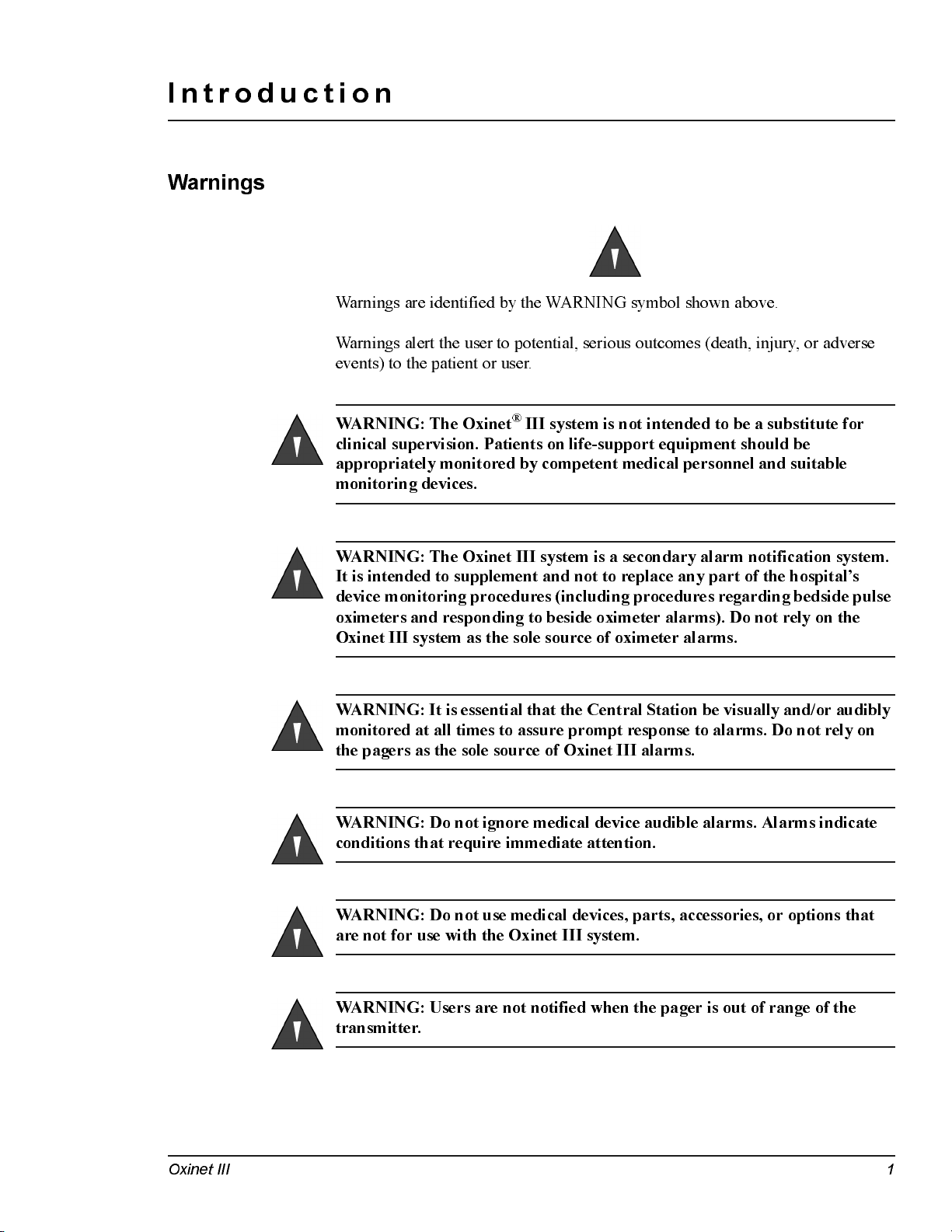
Warnings
Warnings are identified by the WARNING symbol shown above.
Warnings alert the user to potential, serious outcomes (death, injury, or adverse
eve n ts) to the pati e n t or user.
WARNING: The Oxinet® III system is not intended to be a substitute for
clinical supervision. Patients on life-support equipment should be
appropriately monitored by competent medical personnel and suitable
monitoring devices.
WARN ING : The Oxi n e t III system i s a secondar y alarm noti f i cati on system.
It is intended to supplement and not to replace any part of the hospital’s
device monitoring procedures (including procedures regarding bedside pulse
oximeters and responding to beside oximeter alarms). Do not rely on the
Oxinet III system as the sole source of oximeter alarms.
WARNING: It is essential that the Central Station be visually and/or audibly
monitored at all times to assure prompt response to alarms. Do not rely on
the pagers as the sole source of Oxinet III alarms.
WARNING: Do not ignore medical device audible alarms. Alarms indicate
conditions that require immediate attention.
WARNING: Do not use medical devices, parts, accessories, or options that
are not for use with the Oxinet III system.
WARN ING : U sers are not n oti f i ed wh en the pager i s out of ran ge of th e
transmitter.
Oxinet III 1
Page 8
Introduction Service Manual
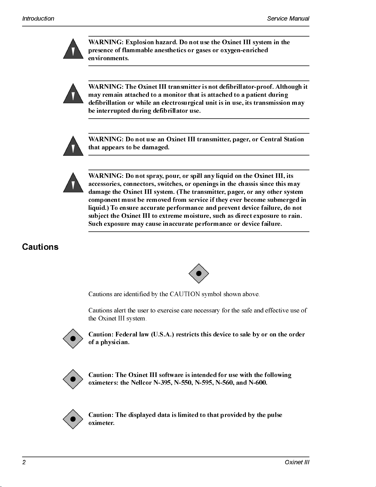
WARNING: Explosion hazard. Do not use the Oxinet III system in the
presence of flammable anesthetics or gases or oxygen-enriched
environments.
WARNING: The Oxinet III transmitter is not defibrillator-proof. Although it
may remain attached to a monitor that is attached to a patient during
defi bri l lat ion or whil e an ele ctrosu rgi cal u n i t is in use, it s tran smission may
be inte rrupted durin g defibri ll ator use .
WARNING: Do not use an Oxinet III transmitter, pager, or Central Station
that appears to be damaged.
WARNING: Do not spray, pour, or spill any liquid on the Oxinet III, its
accessories, connectors, switches, or openings in the chassis since this may
damage th e Ox inet III system. (T h e transm i tter, pager, or any other system
component must be removed from service if they ever become submerged in
liquid.) To ensure accurate performance and prevent device failure, do not
subject the Oxinet III to extreme moisture, such as direct exposure to rain.
Such exposure may cause inaccurate performance or device failure.
Cautions
Cautions are identified by the CAUTION symbol shown above.
Cautions alert the user to exercise care necessary for the safe and effective use of
the Oxinet III system.
Caution: Federal law (U.S.A.) restricts this device to sale by or on the order
of a physician.
Cauti on : Th e O xi net III software is inte n d ed f or u se wit h th e fol l owing
oximeters: the Nellcor N-395, N-550, N-595, N-560, and N-600.
Caution: The displayed data is limited to that provided by the pulse
oximeter.
2 Oxinet III
Page 9
Service Manual Introduction
Cauti on : Re f er to th e ope rator ’s man uals for th e speci f i c pu l se oxi meter for
oximeter warnings and cautions.
Caution: Oxinet III software is intended to run on computers that meet the
minimum requirements set fo r th in t he Sp e ci fica t io ns c ha pt e r o f t his manual .
No applications other than those specified should be installed or executed on
the application server.
Notes
Manual Overview
Notes are identified by the
Notes contain important information that may otherwise be overlooked or missed.
This manual contains information for the Oxinet III system. All users should read
this manual completely. More experienced users can use this manual as a
reference.
The latest versions of this service manual and the operator’s manual are available
online, along with other Nellcor oximetry manuals, at:
http://www.mallinckrodt.com/respiratory/resp/Serv _Supp/P roductManuals.html
Note
symbol shown above.
Oxinet III 3
Page 10

Introduction Service Manual
4 Oxinet III
Page 11
System Overview
Intended Use
The Oxinet III system transmits data from the N-395, N-550, N-595, N-560, or
N-600 pulse oximeter to the Central Station for patient monitoring, via a wired or
wireless conf igur a t ion . T he Central St a t ion di s p la ys a ll monit or ed rooms , releva nt
pulse oximeter data, and alarms.
WARN ING : The Oxi n e t III system i s a secondar y alarm noti f i cati on system.
It is intended to supplement and not to replace any part of the hospital’s
device monitoring procedures (including procedures regarding bedside pulse
oximeters and responding to beside oximeter alarms). Do not rely on the
Oxinet III system as the sole source of oximeter alarms.
The intended patient population is comprised of adult, pediatric, and neonatal
patients. The intended environments of use are hospitals and hospital-type
facilities. Hospital use typically covers such areas as general care floors, operating
rooms, special procedure areas, and intensive and critical care areas within the
hospital and hospital-type facilities, such as surgicenters, sub-acute centers,
special nursing facilities, and sleep labs, outside of the hospital. The Oxinet III
system is for use by prescription only.
Oxinet III 5
Page 12
System Overview Service Manual
Description
The Oxinet III software collects and distributes time-sensitive oximetry data via
wired or local network wireless technology. Making use of the Intranet’s security
and c o nn ectiv i ty standard s, th e Oxin e t III software e n abl e s the re v i e w and
surveillance of medical device settings and real-time patient data remotely, using
a standard HTML compatible web browser.
The components that make up the wireless and wired systems are listed below.
Wireless Configuration:
• Pulse Oximete r (su itabl e fo r u se w i th in the patien t en v i ro n men t)
• Transmitter (suitable for use within the patient environment)
• Access Point
• Router/Switch
• Central Station (application server)
• Oxinet III Operator’s Manual
• Pager Transmitter (optional)
– Pagers, at least two, if pager option installed
Wired Configuration:
• Pulse Oximete r (su itabl e fo r u se w i th in the patien t en v i ro n men t)
• Communication Server
• Router/Switch
• Central Station (application server)
• Oxinet III Operator’s Manual
• Pager Transmitter (optional)
– Pagers, at least two, if pager option installed
Each of these systems is discussed in more detail in the following sections.
6 Oxinet III
Page 13
Service Manual System Overview
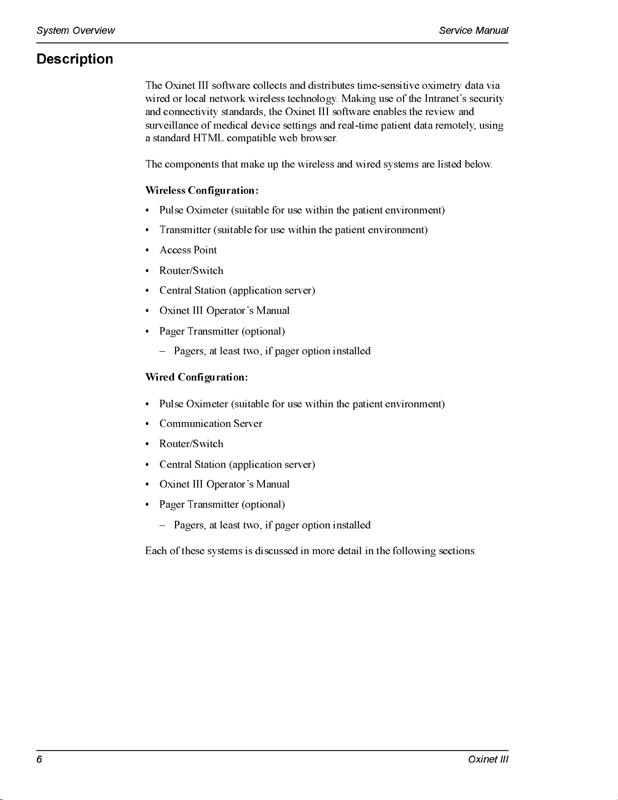
Wireless Configuration
In a wireless configuration (Figure 1), each Pulse Oximeter is connected to a
Transmitter. Each Transmitter communicates wirelessly with an Access Point,
which is connected through a Router/Switch to the Central Station (application
server), where the patient’s data may be monitored. The Central Station can be
con n e c te d to an opti o n al Pag e r Transm i tter : i f pagers are assig n e d to a patient,
alarms are transmitted from the oximeter to the Central Station, then through the
Pager Transmitter to the assigned pagers.
Figure 1: Wireless Configuration — with Optional Pager Transmitter
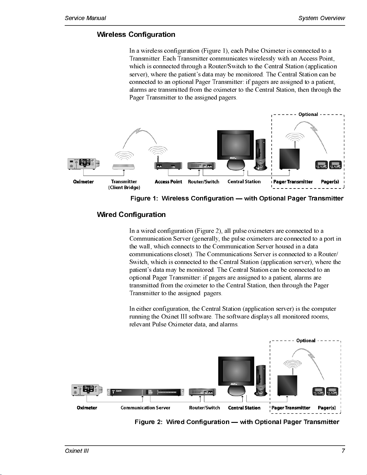
Wired Configuration
In a wired configuration (Figure 2), all pulse oximeters are connected to a
Communication Server (generally, the pulse oximeters are connected to a port in
the wall, which connects to the Communication Server housed in a data
communications closet). The Communications Server is connected to a Router/
Switch, which is connected to the Central Station (application server), where the
patient’s data may be monitored. The Central Station can be connected to an
optional Pager Transmitter: if pagers are assigned to a patient, alarms are
transmitted from the oximeter to the Central Station, then through the Pager
Transmitter to the assigned pagers.
In either configuration, the Central Station (application server) is the computer
running the Oxinet III software. The software displays all monitored rooms,
relevant Pulse Oximeter data, and alarms.
Figure 2: Wired Configuration — with Optional Pager Transmitter
Oxinet III 7
Page 14
System Overview Service Manual
Alarms
Alarms are indicated both audibly and visually at the Central Station. If the
optional paging system is used, an alarm text message is transmitted to a pager,
displaying the room number, patient name, alarm message, SpO
rate at the time of the al arm.
value, and pulse
2
Reports
Pagers
Note:
The Oxinet III software performs database maintenance automatically: the
software temporaril y closes t he p rog ra m, p erf or ms dat a b a s e fi le maint ena nce, and
relaunches the program at 10:05 am every day. This maintenance procedure
normally takes less than 45 seconds to run.
During the brief period that database
maintenance is in progress, the system does not process any incoming data —
including alarms.
The Oxinet III software allows up to 72 hours of monitored data to be stored,
trended, and retrieved in a variety of printable reports. Reports can be run at any
time or periodic snapshots of oximetry data can be scheduled at intervals selected
by the clinician.
Use of pagers with the Oxinet III system is optional, since patients are being
continuously monitored at the Central Station. If you decide to assign pagers to a
patient, you should assign both a primary and a different secondary pager. The
primary pager receives the alarm page within 10 seconds of the alarm. If no one
resp onds to the alarm b y either s ilencing the alarm at the oximeter or r es olv ing t he
reas on for t he al ar m, t he s yst em sends a not if ica t ion t o t he seconda ry pa ger within
30 to 120 seconds of the primary page, depending on the settings for your
Oxinet III system. The range of operation from pager transmitter to pager is
150 feet with no intervening structures.
WARNING: It is essential that the Central Station be visually and/or audibly
monitored at all times to assure prompt response to alarms. Do not rely on
the pagers as the sole source of Oxinet III alarms. The Oxinet III system is a
secondary alarm notification system. It is intended to supplement and not to
replace any part of the hospital's device monitoring procedures (including
procedures regarding bedside pulse oximeters and responding to bedside
oximeter alarms).
8 Oxinet III
Page 15
Service Manual System Overview
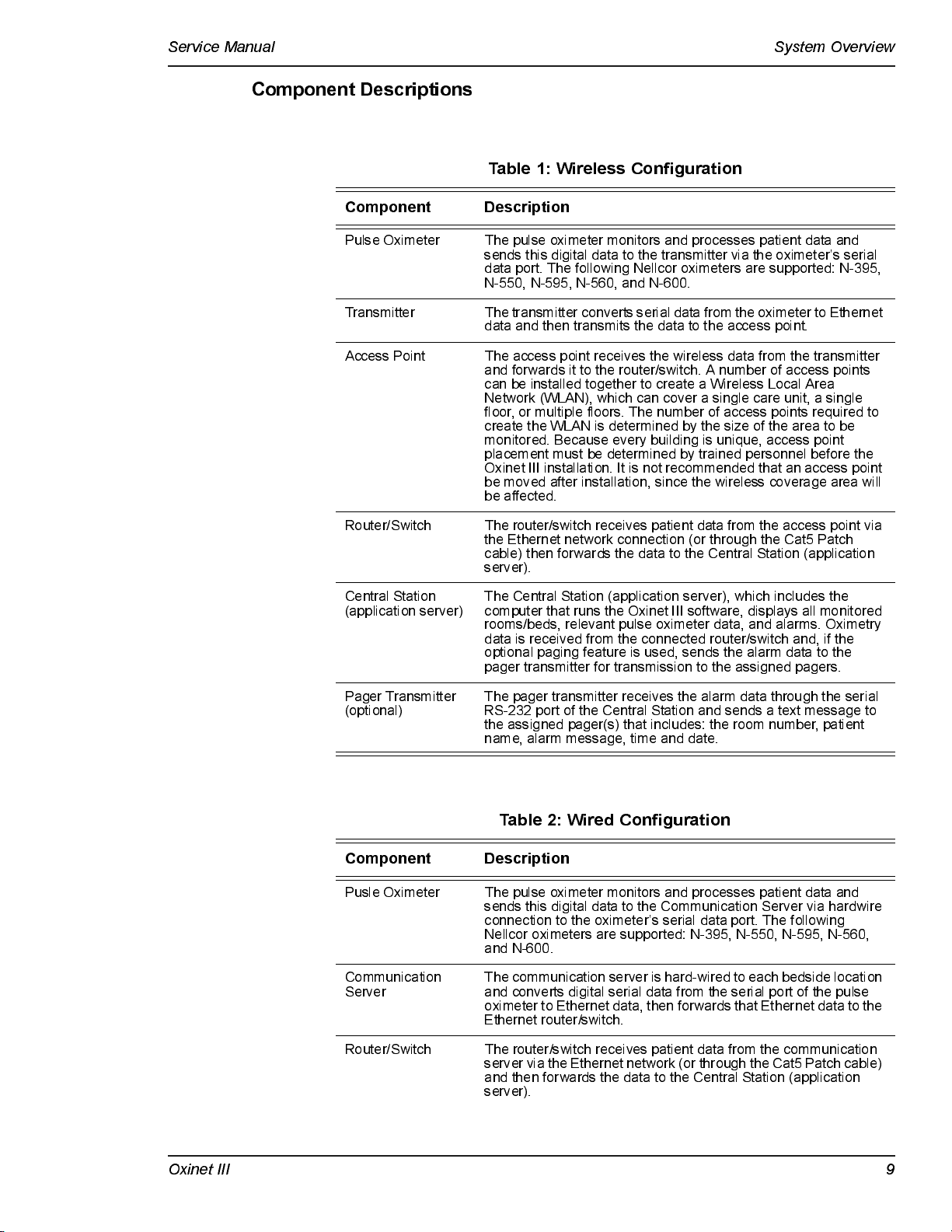
Component Descriptions
Table 1: Wireless Configuration
Component Description
Pulse Oxime te r The pulse ox imete r moni tors and proces s es pati e nt da ta and
Transmitter The transmitter converts serial data from the oximeter to Ethernet
Access Point The access point receives the wireless data from the transmitter
Router/Switch The router/switch receives patient data from the access point via
Central Stati on
(application server)
sends this digital data to the transmitter via the oximeter’s serial
data port. The following Nel l cor ox imete rs ar e supporte d: N-395,
N-550, N-595, N-560, and N-600.
data and then trans mi ts the data to the a cces s poi nt.
and forwards it to the router/switch. A number of access points
can be installed together to create a Wireless Local Area
Network (WLAN), which can cover a single care unit, a single
floor, or multiple floors. The number of access points required to
create the WLAN is determined by the size of the area to be
monitored. Because every building is unique, access point
placement must be determined by trained personnel before the
Oxinet III installation. It is not recommended that an access point
be moved after installation, since the wireless coverage area will
be affected.
the Ethernet network connection (or through the Cat5 Patch
cable) then forwards the data to the Central Station (application
server).
The Central Station (a ppl i ca ti on se rver) , whi ch incl ude s the
computer that runs the Oxinet III software, displays all monitored
rooms/beds, re l e v a nt pul s e ox imete r data , and al a rms . Ox i me t ry
data is received from the connected router/switch and, if the
optional paging feature is used, sends the alarm data to the
pager trans mi t te r for tr a nsmissi on to the as s i gne d pagers .
Pager Transmitter
(optional)
The pager trans mi t te r re ce i ves the al a rm data through the se r i a l
RS-232 port of the Central Station and sends a text message to
the assigned pager(s) that includes: the room number, patient
name, alarm message, time and date.
Table 2: Wired Configuration
Component Description
Pusle Oxime te r The pulse ox imete r moni tors and proces s es pati e nt da ta and
Communication
Server
Router/Switch The router/switch receives patient data from the communication
sends this digital data to the Communication Server via hardwire
connection to the oximeter’s serial data port. The following
Nellcor oximeters are supported: N-395, N-550, N-595, N-560,
and N-600.
The communication server is hard-wired to each bedside location
and converts digital serial data from the serial port of the pulse
oximeter to Ethernet data, then forwards that Ethernet data to the
Ethernet route r /s wi tch.
server via the E thernet n etw ork (or t h ro ugh t h e C a t5 Patch c able)
and then forwards the data to the Central Station (application
server).
Oxinet III 9
Page 16
System Overview Service Manual
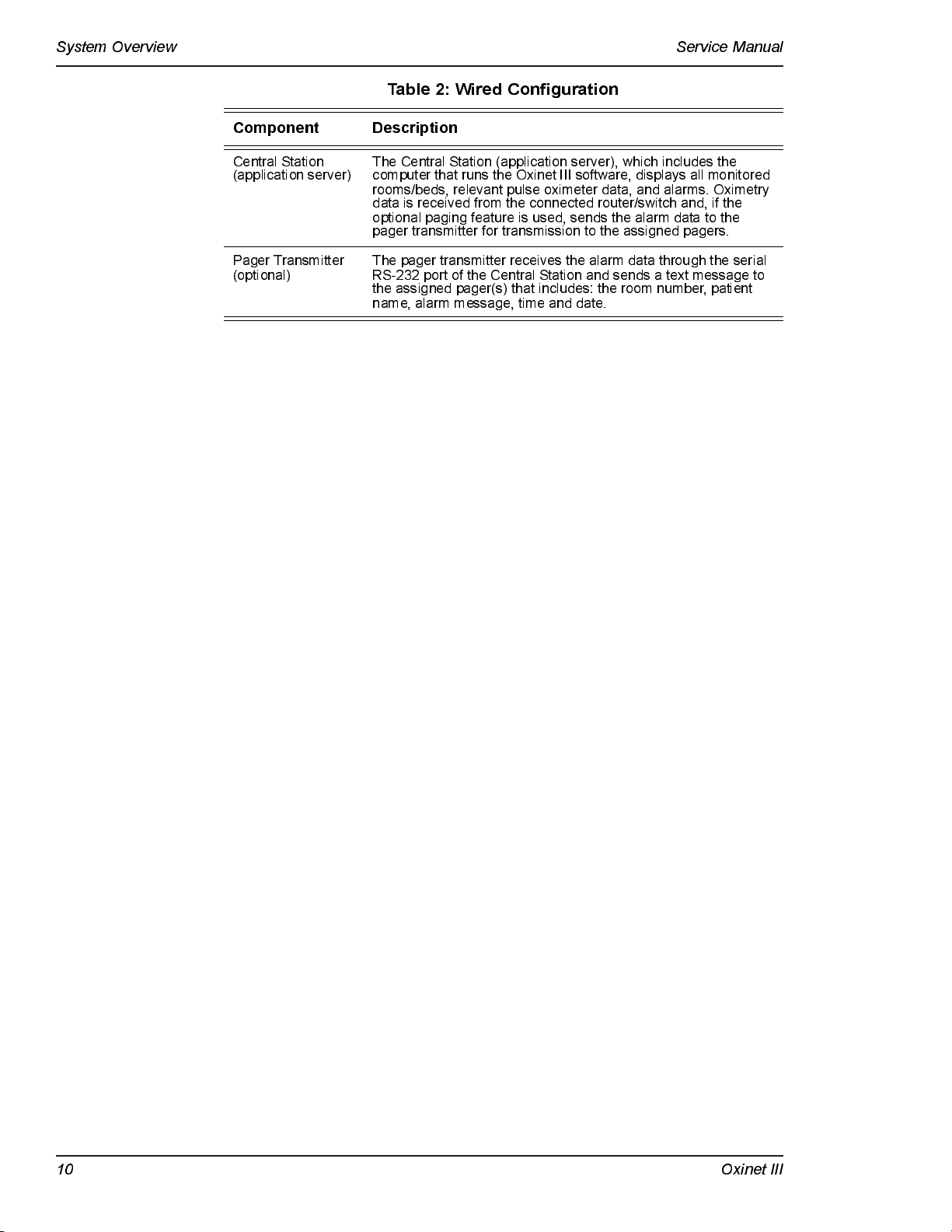
Table 2: Wired Configuration
Component Description
Central Station
(application server)
Pager Transmitter
(optional)
The Central Station (a ppl i ca ti on se rver) , whi ch incl udes the
computer that runs the Oxinet III software, displays all monitored
rooms/beds, re l e v a nt pul s e ox imete r data , and al a rms . Ox i me t ry
data is rece i ved from the connecte d router /s wi t ch and, if the
optional paging feature is used, sends the alarm data to the
pager trans mi t te r for tr a nsmissi on to the as s i gne d pagers .
The pager transmitter receives the alarm data through the serial
RS-232 port of the Central Station and sends a text message to
the assigned pager(s) that includes: the room number, patient
name, alarm message, time and date.
10 Oxinet I I I
Page 17
Installation
Power and Space Requirements
Caution: Oxinet III system power cords should only be connected to
properly groun de d 120V AC , 60 Hz ou tl ets.
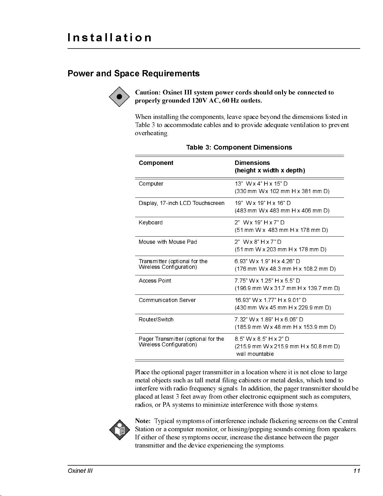
When installing the components, leave space beyond the dimensions listed in
Table 3 to accommodate cables and to provide adequate ventilation to prevent
overheating.
Table 3: Component Dimensions
Component Dimensions
Computer 13” W x 4” H x 15” D
Display, 17-inch LCD Touchscreen 19” W x 19” H x 16” D
(height x width x depth)
(330 mm W x 102 mm H x 381 mm D)
(483 mm W x 483 mm H x 406 mm D)
Keyboard 2” W x 19” H x 7” D
(51 mm W x 483 mm H x 178 mm D)
Mouse with Mouse Pad 2” W x 8” H x 7” D
(51 mm W x 203 mm H x 178 mm D)
Transmitter (optional for the
Wireless Configuration)
Access Point 7.75” W x 1.25” H x 5.5” D
Communication Server 16.93” W x 1.77” H x 9.01” D
Router/Switch 7.32” W x 1.89” H x 6.06” D
Pager Transmitter (optional for the
Wireless Configuration)
6.93” W x 1.9” H x 4.26” D
(176 mm W x 48.3 mm H x 108.2 mm D)
(196.9 mm W x 31.7 mm H x 139.7 mm D)
(430 mm W x 45 mm H x 229.9 mm D)
(185.9 mm W x 48 mm H x 153.9 mm D)
8.5” W x 8.5” H x 2” D
(215.9 mm W x 215.9 mm H x 50.8 mm D)
wall mountabl e
Place the optional pager transmitter in a location where it is not close to large
metal objects such as tall metal filing cabinets or metal desks, which tend to
interfere with radio frequency signals. In addition, the pager transmitter should be
placed at least 3 feet away from other electronic equipment such as computers,
radio s, or PA system s to m i n imize in te r fe renc e with tho se sy ste ms.
Note :
Typical symptoms of interference include flickering screens on the Central
Station or a computer monitor, or hissing/popping sounds coming from speakers.
If either of these symptoms occur, increase the distance between the pager
transmitter and the device experiencing the symptoms.
Oxinet III 11
Page 18
Installation Service Manual
Installation
The Oxinet III system should only be installed by trained Nellcor personnel or
authorized representatives. The installation information provided in this manual
can be used to reconnect the Oxinet III system after moving it.
Wired Configuration
The following Nellcor oximeters are supported in the Oxinet III system:
• N-395
• N-550
• N-595
• N-560
• N-600
The Oximeter data output port must be configured as follows:
• communication protocol — ASCII
• baud rate — 9600
Refer to the Oximeter’service manual for details on Oximeter settings.
Connect the Oximeter to the Communication Server
1
Plug a DB15M/RJ-45 Cat5 Adapter connector into the data port of each Oximeter
(patient room/bed) as shown in Figure 3.
2
Connect a AC power cord to the power input jack on the back of each Oximeter
and plug the other end into AC power outlet.
3
Connect a Cat5 Patch cable from the DB15M/RJ-45 connector of each Oximeter
to an available serial port on the back of the Communication Server and take note
of the room sequence versus the communication serial port number (Figure 3).
Connect the Communication Server to the Router/Switch
1
Connect the Cat5 Patch cable from the 10/100 Base-T network port on the
Communication Server to any available numbered RJ-45 LAN port on the Router/
Switch as shown in Figure 3 (
DO NOT use the port labeled “WAN”
).
2
Connect a AC power cord to the power input jack on the back of the
Communication Server and plug the other end into one of the battery backed-up
AC power outlets of the UPS.
3
Connect th e DC bar r el connector end of the DC Adap ter Power cable to the round
DC jack on the back of the Router/Switch and plug the AC end into one of the
battery backed-up AC power outlets of the UPS (Uninterruptible Power Supply).
12 Oxinet I I I
Page 19
Service Manual Installation
Connect the Router/Switch to the Central Station
Connect a Cat5 Patch cable from any of the numbered RJ-45 LAN ports on the
back of the Router/Switch to the network port in the back of the Central Station
(Figure 3).
Connect the Central Station to Pager Transmitter (Optional)
This procedure needs to be perform only if your system includes the optional
Pager Transmitter.
1
Connect power cord from the power jack on the back of the Central Station to one
of the battery backed-up AC power outlets of the UPS.
Caution: To avoid damaging the Pager Transmitter, connect its antenna
before connecting power to the Pager Transmitter.
2
Connect the antenna for the Pager Transmitter to the BNC connector on the Pager
Transmitter (Figure 3).
3
Connect the Central Station’s antenna as shown in Figure 3.
4
Connect one end of the two-ended RS-232 serial cable to the
the Central Station, and connect the other end to the
RS232C Interface
COM1
serial port of
serial port
on the left side of the Pager Transmitter (Figure 3).
5
Connect the DC power cable into the
12V DC
power port of the Pager Transmitter
and plug the AC cord into the AC power outlet (Figure 3).
6
Connect the mouse and keyboard to the Central Station (Figure 3).
Connect the Printer to the Central Station
You need to connect a printer to the Central station in order to print Oxinet III
reports.
1
Connect the printer cable from the printer to the parallel port connector on the
back o f the PC porti on o f the Central Statio n (Fi g ur e 3).
2
If you are us ing a US B p r inter, connect the USB cable to the USB port on the back
of the PC portion of the Central Station (Figure 3).
Oxinet III 13
Page 20

Installation Service Manual
Figure 3: Wired Configuration System Connection
14 Oxinet I I I
Page 21

Service Manual Installation
Wireless Configuration
Connect the Oximeter to the Transmitter
The following Nellcor oximeters are supported in the Oxinet III system:
• N-395
• N-550
• N-595
• N-560
• N-600
The oximeter data output port must be configured as follows:
• communication protocol — ASCII
• baud rate — 9600
Refer to the Oximeter’service manual for details on Oximeter settings.
1
Place the Transmitter (Client Bridge) near or on top of the Oximeter (Figure 4).
2
Connect the Oximeter to the Transmitter using the transmitter’s RS-232 cable
(Figure 4).
3
Connect one end of the AC Y-cord to each unit (Oximeter and Transmitter) and
plug the other end into the AC outlet (Figure 4).
Connect the Access Point to the Router/Switch
1
Install a Cat5 cable from the RJ45 jack on the back of the Access Point to any of
the numbered RJ-45 LAN ports on the back of the Router/Switch (Figure 4).
2
Connect the Access Point Antenna to the Prima ry Antenna Connect or on t he ba ck
of the Access Point (Figure 4).
3
Connect DC b a r rel connect or end of t he DC Ada p ter Power cab le t o the round DC
jack on the back of the Router/Switch and plug the AC plug end into an AC outlet
(Figure 4).
4
Connect DC power to the Access Point by performing either the
Point Power Supply Connection
Distributed Powe r Supply Connection
procedure or the
procedure.
Multiple Access Points
Single Access
a. Singl e A cc ess Point Power Supply C on n e cti on
if a single Access Point is to be installed in a location (such as a bookcase or
tall shelf) where an AC power outlet is available.
• Plug the DC barrel connector end of the DC Adapter Power cable into
the round power jack on the access point and plug the AC power cord
into an AC outlet (Figure 4).
Oxinet III 15
— This option can be used
Page 22

Installation Service Manual
b. Multiple Access Points Distributed Power Supply Connection
— This
option c an di stribu te 15V D C po wer to as m an y as six acc e ss poi n ts,
concurrently. The distributed power supply is useful when multiple access
points are used to cover larger areas or when there is no AC outlet near the
access point (such as when an access point is installed in a ceiling plenum).
Perform the following steps to connect DC power to multiple access points:
1. Run a cable between the distributed power supply and each Access Point
separately. Since a data cable also has to be run to each Access Point, a
cable contractor can pull the two cables at the same time.
The c abl e ty pe re qu i re d fo r the d i stribu te d power supply is a stranded
18 AWG, STP (shielded twisted pair) with an overall foil shield with a
rating appropriate for the application (plenum rated, for example). Follow
local, state, and national regulations regarding cabling. An electrician or
licensed contractor should be consulted. The power cable must be
terminated with a special barrel connector at the access point. The white
striped connector is positive.
2. Plug the barrel connector into the round power jack on the Access Point.
3. Connect the opposite end of the power cable to terminal blocks on the
power distribution panel of the distributed power supply. When
terminating the ends of the power cable, observe polarity.
4. Plug the AC power cord of the distributed power supply into an
AC outlet.
5. Repeat the process for each Access Point.
Note :
When multiple access points are combined to cover large areas, it might be
necessary to use multiple switches and multiple distributed power supplies.
Connect the Router/Switch to the Central Station
Connect a Cat5 cable from any of the numbered RJ-45 LAN ports on the back of
the router/switch to the network port in the back of the PC portion of the Central
Station (Figure 4).
Connect the Central Station to the Pager Transmitter
Caution: To avoid damaging the Pager Transmitter, connect its antenna
before connecting power to the Pager Transmitter.
1
Connect the antenna for the Pager Transmitter to the BNC connector on the Pager
Transmitter (Figure 4).
2
Connect one end of the two-ended RS-232 serial cable to the
the PC portion of the Central Station, and connect the other end to the
Interface
16 Oxinet I I I
serial port on the left sid e o f the Pa ger Transmitte r (Fig u re 4).
COM1
serial port of
RS232C
Page 23

Service Manual Installation
3
Connect the DC power cable into the
12V DC
power port of the Pager Transmitter
and plug the AC cord into the AC power outlet (Figure 4).
4
Connect the PC portion of the Central Station to an AC power outlet, connect the
DC power to the Monitor Portion of the Central Station (via the DC power cable),
and connect the mouse and keyboard to the Central Station (Figure 4).
Connect the Printer to the Central Station
You need to connect a printer to the Central station in order to print Oxinet III
reports.
1
Connect the printer cable from the printer to the parallel port connector on the
back o f the PC porti on o f the Central Statio n (Fi g ur e 4).
2
If you are us ing a US B p r inter, connect the USB cable to the USB port on the back
of the PC portion of the Central Station (Figure 4).
Oxinet III 17
Page 24

Installation Service Manual
Figure 4: Wireless Configuration System Connection
18 Oxinet I I I
Page 25

Administrative Functions
Central Statio n
The Central Station performs various Administrative functions for the Oxinet III
system.
Caution: The procedures described in this chapter must be performed by
qualified service personnel.
All but one of the Administrative functions are password-protected to prevent
access by unauthorized personnel. The password is provided in this chapter.
There are two ways to gain access to the Administrative functions, either via an
externally connected keyboard or by using the on screen “touchscreen” keyboard.
You may also want t o connect a mous e instead of us ing t he t o uchs creen cap a b il it y.
To connect the mouse and the keyboard to the appropriate ports, see Figure 3 or
Figure 4 in the Installation chapter of this manual.
Once the mouse and the keyboard are connected, use the
the Central Station (Figure 5).
On/Off
button to restart
Figure 5: Central Station Keyboard Display and On/Standby Button
Oxinet III 19
Page 26

Admi nistrat ive Fun ction s Service Manual
Funciton Keys Explained
The keyboard’s function keys provide access to the Administrative functions of
the Oxinet III Central Station. Table 4 lists and describes each of the function
keys.
Table 4: Function Key s Ex plai ned
Key Descripti on
F5 Allows you to refresh screen.
F7 Allows you to align the touchscreen.
F8 Allows you to adjust the volume.
F9 Allows you to backup the current system configuration or to restore
F10 Allows you to change the various alarm settings, add/delete
F11 Allows you to manually initiate database maintenance.
the most current backed-up version of the system configuration.
pagers, modify the room list, and schedule snapshots.
Refreshing the Screen (F5)
Refreshing the screen enables you to restart the current screen if there is a problem
with the Cent r a l S tation. For ex amp le, you may want t o us e t he r efr es h f unct ion a s
the first step when troubleshooting error messages such as Network
Communication Error or Pulse Oximeter Communication Error, if the operational
status of the Central Station is suspect, or when troubleshooting system
interference problems. This is the only Administrative function that is not
password-protected; simply press the
screen.
the lower tool bar
A screen refresh can also be performed by touching the Oxinet III logo on
.
Aligning the Touchscreen (F7)
Alignment of the touchscreen is necessary if you notice the cursor is not lined up
with your finger when using the touchscreen. This function is password-protected.
F5
key on the keyboard to refresh the
1
Press the
F7
key on the keyboard.
The uShield dialog box appears (Figure 6).
Figure 6: uShield Dialog Box
2
Type the Administrative function password,
1234
, then pre ss or c li c k the
Ok
button.
20 Oxinet I I I
Page 27

Service Manual Administrative Functions
The
Elo Touchscreen Properties
dial og bo x appea rs (Fi g ur e 7).
Figure 7: Elo Touchscreen Properties Dialog Box
3
Press or click the
The system will guide you through the alignment process. When complete, press
or click the
OK
function and return to the
Adjusting Volume (F8)
This password-protected function enables you to control the Central Station
volume.
1
Press the
The uShield dialog box appears (Figure 6).
2
Type the Administrative function password,
button
3
The
F8
key on the keyboard.
.
Volume Control
Align
button.
button on the
Elo Touchscreen Properties
Main Display
dial og bo x appea rs (Fi gu r e 8).
screen.
1234
dialog box to close this
, then pre ss or c li c k the
Ok
Oxinet III 21
Page 28

Admi nistrat ive Fun ction s Service Manual
Figure 8: Volume Control Dialog Box
4
Make the following adjustments as desired:
Warning: The Oxinet III Central Station should NOT be muted.
• If the Volume Control’s
(turne d off); c lear the ch eck box by c l ickin g it to un - m u te (tur n -o n ) the
volume.
• Raise and lower the volume by clicking and dragging the Volume slider in the
Vol ume Co nt r o l
section — dr ag it up to rais e t he vol ume and down t o lower t he
volume.
• When you have completed the volume adjustments, press or click the X in the
upper right corner of the
return to the
Main Display
Using Backup/Restore (F9)
Use this password-protected function to back up the current system configuration
or to restore the most current backed-up version of the syst em configuration. A
USB Memory Device is needed to perform this function.
Backing up the Current System Configuration
1
Press the F9 key on the keyboard.
The
Oxinet Backup/R estore Wizard
through the backup process.
Mute all
che c k box is se lecte d , th e vo l u m e is mu te d
Volume Control
screen.
opens (Figure 9). The wizard will guide you
dialog box to close this function and
Note:
Pressing (or clicking) the
Cancel
button en abl e s y o u to c an cel this ac ti o n
and close this function.
22 Oxinet I I I
Page 29

Service Manual Administrative Functions
Figure 9: Oxinet Backup Wizard
2
Type the Administrative function password,
1234
, then pre ss or c li c k the
Next
button.
The
Select an action
scree n appe ar s (Fig u re 10).
Figure 10: Backup/Restore Function — Select an Action
The system determines if the USB Memory Device is installed. If the device is
installed, the
device is not installed, the
Note:
Backup Device Detected
No Backup Device Detected
Pressing (or clicking) the
Cancel
message appears (Figure 11). If the
message appears.
button en abl e s y o u to c an cel this ac ti o n
and close this function.
Oxinet III 23
Page 30

Admi nistrat ive Fun ction s Service Manual
Figure 11: Backup Function
3
Press or click the
Next
button.
The system begins the backup process and displays the message:
Progress
(Figure 12). The desktop outside the Backup screen will be black.
Figure 12: Backup in Progress
4
When the backup process is complete, the word
Done
appears (Fig u re 13).
Backup in
24 Oxinet I I I
Page 31

Service Manual Administrative Functions
Figure 13: Backup in Progress — Done
5
Press or click the
Next
button.
The final message,
6
Click the
Finish
Backup Com p leted ,
is displayed (Figure 14).
Figure 14: Backup Completed
button to close this function.
Oxinet III 25
Page 32

Admi nistrat ive Fun ction s Service Manual
Restoring the Most Current Backed-up Version
Make sure the USB Memory Device, containing the most current backed-up
version, is in place.
1
Press the
The
the restore process.
F9
key on the keyboard.
Oxinet Backup Wizard
opens (Figure 15). The wizard will guide you through
Note:
Pressing (or clicking) the
Cancel
and close this function.
Figure 15: Backup/Restore Wizard
2
Type the Administrative function password,
button.
button en abl e s y o u to c an cel this ac ti o n
1234
, then pre ss or c li c k the
Next
The
Select an action
scree n appe ar s (Figure 16).
Figure 16: Backup/Restore Function — Select an Action
3
Select the
26 Oxinet I I I
Restore
option (Figure 16), then press or click the
Next
button.
Page 33

Service Manual Administrative Functions
Note:
Pressing (or clicking) the
Back
button at any po in t in the Wiza rd e na bles
yo u to re turn to the prior Wizar d sc reen .
The system determines if the USB Memory Device is installed. If the device is
installed, the
device is not installed, the
4
Press or click the
Restore Devi ce Detected
No Backup Device Detected
Next
button.
messag e appe ar s (Fig u re 17). If the
message appears.
Figure 17: Restore Function
5
If you have more than one version backed up, the system asks you to select the
version you want to restore; the most recent version will be the current selection.
Press or click the drop-down arrow to view and select another saved version
(Figure 18).
Figure 18: Restore Function —Select a Version
6
Press or click the
7
You will then be asked to confirm your version selection (Figure 19). Press or
click the
the
Oxinet III 27
Next
Back
button to retu rn to the pri o r scr e e n (Fi g u re 18).
Next
button.
but t o n t o cont inue. O r, if you have s elected the wrong version, click
Page 34

Admi nistrat ive Fun ction s Service Manual
Figure 19: Restore Function — Confirm the Version
8
The system begins the backup process and displays the message:
Progress
(Figure 20).
Restore in
Figure 20: Restore in Progress
When the backup process is complete, the word
28 Oxinet I I I
Done
appears (Fig u re 21).
Page 35

Service Manual Administrative Functions
Figure 21: Restore in Progress - Done
9
Press or click the
Next
button.
The final message,
10
Click the
Finish
Restore Completed
, is displayed (Figure 22).
Figure 22 : Restor e Comple t ed
button to close this function.
Oxinet III 29
Page 36

Admi nistrat ive Fun ction s Service Manual
Oxinet Control Panel (F10)
1
Press the
The uShield dialog box appears (Figure 6).
2
Type the Administrative function password,
button.
The
F10
key on the keyboard.
Oxinet Control Panel
opens (Figure 23).
1234
, then pre ss or c li c k the
Ok
Figure 23: Oxinet Control Panel
The
Oxinet Control Panel
menus enable you to:
• Change the various alarm settings
• Add/delete pagers
• Modify the room list
• Schedule snapshots
There are four tabs at the top of the
menu:
Alarms, Pagers, Room s
, and
(or click) the corresponding tab.
Oxinet Control Panel
Schedule Snap Shot
screen tha t ident i fy each
. To see a menu, press
30 Oxinet I I I
Page 37

Service Manual Administrative Functions
Alarms Menu
The
Alarms
Control Panel
menu (Figure 24) is the first screen that appears when the
opens.
Oxinet
Figure 24: Alarms Menu
The first three columns contain alarm information (description, abbreviation, and
level).
1
To change settings in the
or
Snap Shot
colu mns, pre ss (or c l ick) w i th in the ce ll fo r the se ttin g y o u want to
Workstation Audible, Central Station Tone, Se nd Pa ge
change.
A drop-down arrow appears (Figure 24).
2
Press (or click) the arrow and the list of options appears as shown in Figure 24.
3
Press (or click) the option to select it.
The change is made.
Table 5 lists and descri be s the al arm setting s in the
Alarm
menu.
,
Oxinet III 31
Page 38

Admi nistrat ive Fun ction s Service Manual
Table 5: Alarms Settings
Description This is the message that appears on the Central Station
Abbrev If pagers are assigned to a patient and the
Level The settings in this column determines the priority level of
Works ta ti on
Audible
Central Station
Tone
Send Page The settings in this column determine whether or not this
Snapshot The settings in this column determine if a snapshot will
when the alarm o c c u r s ( c an b e edited by a Nellco r S ervic e
technici a n only)
the
Send Page
message that will be sent to the pager (can be edited by a
Nellcor Service technician only).
an alarm:
technici a n only).
The settings in this column determine if an audible alarm
sounds on the Central Station when this alarm occurs:
Audible
or
The settings in this column determine the audible tone for
the alarm:
(none)
.
alarm will trigger an alarm page, if pagers are assigned to
the patient:
automatically be taken when this alarm occurs:
.
column is selected, this is the pager
Low
or
High
(can be edited by a Nellcor Service
Off
. Default setting is
FivePulse, ThreePulse, Constant Tone
Yes
or No.
Audible
Yes
.
option in
, or
Yes
or No.
Pagers Menu
To Set Interval Betwee n In i ti al P age to Pri mary Pager an d P age to
Secondary Pager:
1
Press (or c l ick) the
Pagers
tab to open the
Pagers
menu as shown in Figure 25.
Figure 25 : Pager s Menu — Initia l
32 Oxinet I I I
Page 39

Service Manual Administrative Functions
2
Use the
Send Secondary Page(s)
field to set the interval (in seconds) between the
initial page to the primary pager and the page to the secondary pager(s), if pagers
are assigned to the patient. For example, if you type
30
(Figure 2 5 ) , t he s econdar y
pager notification will occur 30 seconds after the initial page occurs (if no one
responds to the initial alarm page to either silence the alarm at the oximeter or
resolve the reason for the alarm).
To Add a Pager :
1
Press (or c l ick) the starre d (*) ce l l (Fi gu r e 25) in the
Pager Nam e
column.
This inserts the cursor so you can type the pager name or number. Backspace to
delete the word
New
(Figure 26).
Figure 26: Pagers Menu — Adding Pager
2
Press (or click) the cell in the
example
Oxinet III 33
103
(Figure 27)
.
Pager Name
column and type the pager number, for
Page 40

Admi nistrat ive Fun ction s Service Manual
Figure 27: Pagers Menu — Entering Pager Name
3A
Press (or c l ick) the c e l l in the
nam e an d n u m ber, for exam ple
Pager Number/E-mail
103A50
(Figure 27)
column and type the pager
— the pager number is
indi c a te d on the bac k of the pag e r (i n th is e xample the pag e r nu mber i s 103).
OR
3B
If the Oxinet III system is connected to a SMTP e-mail system on the hospital’s
intran e t and the Oxine t III sy ste m i s co n n e c ted to that in tran e t, you c a n ty pe an
e-mail address instead, then change the
Type
to
E-Mail
as shown in Figure 28.
Figure 28: Pagers Menu — Entering Pager E-mail
34 Oxinet I I I
Page 41

Service Manual Administrative Functions
To Edit a Pager :
Press (or click) the cell containing the information you want to modify, then make
the change.
To Del ete a Pager :
Press (or c l ick) the area to the l e ft of th e row to hi gh l i g h t the row to be dele te d ,
then press the
Delete
key on the keyboard.
Rooms Menu
Caution: Do not make changes to the room list while patients are being
mon i tored — you must f i rst di sch ar ge all patie n ts f rom the Oxi n et III
system, then make any n e cessary ch an ge s to the list.
The
Unit
column enables you to group rooms/beds in categories that make sense
for yo u r fac i li ty. If y o u h av e m u l tipl e U ni ts in the sy ste m, button s re pre se n tin g
each of those Units will appear at the top of the
switc h the
Unit, the
Monitor
Step Down
view from one Unit to another. Figure 29 shows only one
Unit.
Monitor
screen, so you can
The
RoomSeq
the
Available Room Li st
The
Tech Page
field determines the order in which the rooms will be displayed on
and the
Monitor
screens.
button is reserved for use by Nellcor Service technicians to clear
room assi gn men ts in the e v e n t of a pro ble m and is passw o rd -pro te cted .
Figure 29: Rooms Menu
Oxinet III 35
Page 42

Admi nistrat ive Fun ction s Service Manual
Schedule Snap Shot Menu
Use the Schedule Snap Shot menu to set the times for scheduled snapshots to
occur (refer to the Running Reports chapter of the operator’s manual for more
information about Snapshots). Press (or click) the check box next to the desired
time to select or clear it. For example, in Figure 30, snapshots will be taken for all
patients in the Oxinet III system at midnight, at noon, at 4 am and 4 pm, and at
8 am and 8 pm.
Figure 30: Schedule Snap Shot Screen
36 Oxinet I I I
Page 43

Service Manual Administrative Functions
Maintenance (F11)
Note :
The Oxinet III software per for ms da t a b ase maintenance automat i call y. The
software temporaril y closes t he p rog ra m, p erf or ms dat a b a s e fi le maint ena nce, and
relaunches the program at 10:05 am every day. This maintenance procedure
normally takes less than 45
does not process any incoming data, including alarms.
seconds to run.
During this brief period, the system
To manually initiate the
database maintenance process, perform the following procedure.
To Manually Initiate Database Maintenance
Use the
password-protected.
1
Press the
The uShield dialog box appears (Figure 6).
2
Type the Administrative function password,
button.
When maintenance begins, the
shoul d take u p to 5 min u tes to com pl ete
main te n a nce is c o m pl e te , the sy ste m retur n s y o u to the
F11
function to
F11
key on the keyboard.
manually initiate database maintenance
1234
, then pre ss or c li c k the
Please wai t.. M ain tenan ce is runnin g. Thi s
message appears (Figure 31). When
Monitor
. This function is
sc r een .
Ok
Figure 31: Database Maintenance
Oxinet III 37
Page 44

Admi nistrat ive Fun ction s Service Manual
38 Oxinet I I I
Page 45

Maintenance
Service
If servi ce is needed for a ny of t he O x inet III sys t em component s , cont a ct q ua lif ied
service personnel or your local Nellcor representative.
The Pager requires periodic replacement of the battery. Refer to the operator’s
manual for battery replacement instructions. The latest version of the operator’s
manual is available online at:
http://www.mallinckrodt.com/respiratory/resp/Serv_Supp/ProductManuals.html
Note :
software temporaril y closes t he p rog ra m, p erf or ms dat a b a s e fi le maint ena nce, and
relaunches the program at 10:05 am every day. This maintenance procedure
normally takes less than 45
does not process any incoming data, including alarms.
database maintenance process, refer to the section
of the Administrative Functions chapter in this manual.
The Oxinet III software per for ms da t a b ase maintenance automat i call y. The
Periodic Safety Checks
It is recommended that the following checks be performed on the transmitter
every 24 months:
• Inspect the transmitter for mechanical and functional damage
• Inspe c t the re l e v a n t safety labe ls fo r legibi l ity
If the labels are not legible, call Nellcor’s Technical Services Department at
1.800.635.5267 or con tac t y o u r l o c al Nellcor re pre se n tati v e .
Cleaning
Caution: Do not spray, pour, or spill any liquid on any of the Oxinet III
comp on ents, its accessorie s, con n e ctor s, switches, or open ings in th e ch assis,
since this m ay dam age the Oxi n et III system.
seconds to run.
During this brief period, the system
To manually initiate the
Maintenance (F11)
on page 37
To clean the p ager or Cent r a l Station screens, us e a clea n clot h desi gned f or us e on
lenses or touch-sensitive screens. To clean the pager or Central Station casings,
use a clean damp cloth and wipe dry.
For surface-cleaning and disinfecting the transmitter, follow your institution’s
procedures or:
• Surface-clean by using a soft cloth dampened with either a commercial,
nonabr a s ive cleaner or a s olution of 70% alcohol in water, and lightly wipe the
surfaces of the transmitter.
Oxinet III 39
Page 46

Maintenance Service Manual
• Disinfect by using a soft cloth saturated with Glutaraldehyde (CIDEXTM or
equivalent) or 10% chlorine bleach in tap water.
Spare Parts
To order spare parts, contact Nellcor’s Technical Services Department at
1.800.635.5267. Spare parts and part numbers are shown in tables 6 and 7. A parts
list for the Oxinet III system is also available online at:
http://www.mallinckrodt.com/respiratory/resp/Serv_Supp/apartweb/main/partaccemenu.html
Table 6: Parts List
Description Part Number
Access Point APOXI3
Transmitter 10006088
Communication Server CS16OXI3
Pager 10005478
Router/Switch ROUTOXI3
Table 7: Accessories List
Description Part Number
Antenna, Pager Transmitter X3440098
Pager Clip-on Holder 10005477
Power Supply, Access Point APPSOXI3
Transmitter, Pager PAGETRAN
Power Supply, Pager Transmitter X3440097
UPS, Uninterruptible Power Supply UPSOXI3
USB Memory Device 10001957
40 Oxinet I I I
Page 47

Service Manual Maintenance
Returning Components
Failure to follow the instructions in this section may result in loss or damage not
covered by any applicable Nellcor warranty.
1. Contact your supplier or local Nellcor office (Technical Services Department,
1.800.635.5267) for a returned goods aut hor iz ation (RGA) number. They will
also provide you with the address for returning the Oxinet III component.
2. Pack the component(s). The best method for returning the component(s) is to
pack t hem in t he or igina l shipping car t on. If the original shi p p ing ca r t on is not
available, use another suitable carton, using sufficient padding to protect the
component. Mark the shipping carton and any shipping documents with the
RGA number. Return the component(s) by any method that provides proof of
delivery.
Oxinet III 41
Page 48

Maintenance Service Manual
42 Oxinet I I I
Page 49

Troubleshooting
Troubleshooting List
Table 8 lists troubleshooting tips for some of the problems that might occur while
operating the Oxinet III system.
Some problems might indicate equipment malfunction. Your Oxinet III system
administ ra tor should b e contact ed to resol ve these typ es of pr oblems . You can also
contact Nellcor’s Technical Services Department at 1.800.635.5267.
Table 8: Troubleshooting
Symptom Cause Corrective Action
Message appears:
wait..M aintenance is running.
This should take few minutes
to complete.
Poor cursor control on the
Central Station
Software Activity Indicator
(colored bars in upper left corner
of screen) st op scrol l i ng
Please
The Oxi net I I I s oftwa re
performs data ba s e
maintenance automatically:
the software temporarily
closes the program,
performs data ba s e fi le
mainte na nce, a nd
rela unches the progra m at
10:05 am every day. This
maintenance procedure
no rm ally t ak es less t h an 4 5
seconds to run.
this brief period, the
system does not process
any incoming data,
including alarms.
Cursor out of alignment. • Connect a keyboard to the Central
Software activity has
stopped.
During
No intervention is needed.
Station and restart it.
• Press F7 key on the keyboard, then
type the Administrative function pass-
word.
• When the
dialog box opens, press the
ton. The system will guide you through
the alignment process.
• When complete, pre s s the OK button
on the
dialog box to close this function.
• Restart the Central Station.
If the probl e m still e x ists, contact
Nellcor’s Technical Services
Department at 1.800.635.5267.
Elo Touchscreen Properties
Elo Touchscreen Properties
Align
but-
Oxinet III 43
Page 50

Troubleshooting Service Manual
Table 8: Troubleshooting (Continued)
Symptom Cause Corrective Action
No display on the Central Station Central Station loss of
No current data is being
displayed for an active oximeter
or several oximeters
power.
Monitor not connected. • Ensure all monitor cables are con-
The UPS has draine d its
battery.
The UPS is not operating
properly.
Data from an active
oximeter is not reaching
the Central Station.
• Ensur e tha t the AC power cord is con-
nected to the power input jack on the
back of the base of the Central Station
and the other end is plugge d into one
of the batter y backed- up AC outlets or
the UPS.
nected.
• Recharge the battery on the UPS.
• Replace the battery, if necessary.
• Replace the UPS.
• Make sure the cable is securely con-
nected to the oximeter’s data port.
• Check that router/switch has power
Wired configuration:
• Check the connection between the
oximeter and communication server
• Check that the communication server
has power.
• Check the connection between the
communication server and the router/
switch.
Wireless configuration:
No current data is being
displayed for any oximeters in
the Oxinet III system.
Data from all active
oximeters is not reaching
the Central Station.
• Check that the transmitter has power.
• Check the connection between the
oximeter and transmitter.
• Check that the access point has
power.
• Check that the Cat5 cable connecting
the ro u t er /s w itc h to the Central Station
is securely connected to any of the
router/s wi t ch’s numbere d ports.
• Check that the other end of the Cat5
cable is securely connected to the net-
work port connection on the back of
the Central Station.
• Check that the router/switch has
power.
Wired configuration:
• Check that the communication server
has power.
• Check the connection between the
communication server and the router/
switch.
Wireless configuration:
• Check that the access point has
power.
• Check the connection between the
access point and the router/switch.
44 Oxinet I I I
Page 51

Service Manual Troubleshooting
Table 8: Troubleshooting (Continued)
Symptom Cause Corrective Action
A pager does not recei ve an
ala rm page
Mult iple pagers d o n ot receive an
alarm
The Central Station i s fr oze n Program error • Re sta r t the Ce ntra l Station.
The pager may not be
assigned to that patient or
the pager may have been
out of range.
The pager transmitter may
have lost power or the cord
connecting the pager
transmitter with the Central
Station may be loose or
disconnected.
• Check the Pager Assignments on the
Central Station to confirm that the
pager is assigned to the room/patient
where the alarm occurred.
• The pager transmitter may have lost
power or the cord connecting the
pager transmitter with the Central
Station may be loose or disconnected.
Confirm that the cord is still securely
attached.
• Confi r m the re d power l i ght for the
pager transmitter is on; make sure the
power supply is still connected to the
back of the pager transmitter.
• If needed, contact Nellcor’s Technical
Serv i ce s De part me nt at
1.800.635.5267.
• Confi r m the re d power l i ght for the
pager transmitter is on.
• Confirm the power supply is still con-
nected to the pager transmitter.
• Check the cord connecting the Central
Station to the pager transmitter to
ensure it is securely connected to the
serial port of the pager transmitter and
the
COM1
port of the Central Station.
If the probl e m still e x ists, contact
Nellcor’s Technical Services
Department at 1.800.635.5267.
Central Station computer
error
Alarms not audible Alarm is not configured as
an audible alert.
Volume is turned off/down
for speakers.
• Restart the Central Station.
If the probl e m still e x ists, contact
Nellcor’s Technical Services
Department at 1.800.635.5267.
• Press the
1. When the uShield dialog box
appears, type 1234 for the
password and press the Ok button.
2. In the Oxinet Control Panel, set the
type of audible alarm desired.
See
page 30 for details.
• Press the F8 key on the keyoard:
1. When the uShield dialog box
appears, type 1234 for the
password and press the Ok button.
2. In the Volume Control dialog box,
raise the volume by clicking and
dragging the Volume slider up.
See
page 21 for details.
• Check Audio cable connection.
F10
key on the keyboard:
Oxinet Control Panel (F10)
Adjusting Volume (F8)
on
on
Oxinet III 45
Page 52

Troubleshooting Service Manual
Obtaining Technical Assistance
For technical information and assistance, or to order parts or a service manual,
contact Nellcor’s Technical Services Department at 1.800.635.5267 or your local
Nellcor representative.
The latest versions of this operator’s manual and the service manual are available
online, along with other Nellcor oximetry manuals, at:
http://www.mallinckrodt.com/respiratory/resp/Serv_Supp/ProductManuals.html
46 Oxinet I I I
Page 53

Specifications
Phy sic al Des ign Requ iremen ts
CPU Minimum 500 MHz processor
Memory Minimum 256 MB SDRAM
Floppy Disk 1.44 MB 3.5-inch Floppy Drive
CD-ROM Read Only
I/O 1 RS-232 port
Physi ca l Di me ns i ons:
Computer 13” W x 4” H x 15” D
Table 9: Central Station
1 Parallel port
8 USB ports
1 Network Ethernet 10/100 port
(330 mm W x 102 mm H x 381 mm D)
Display 17-inch LCD Touchscreen
19” W x 19” H x 16” D
(483 mm W x 483 mm H x 406 mm D)
Wei ght :
Computer 16. 8 lbs
Display 22.9 lbs
−
Storage Temperature
Operating Temperat ure 0 to 45 °C (32 to 113 °F)
Altitude 0 to 3048 meters (0 to 10,000 feet)
Relative Humidity 10% to 95% non-condensing
20 to 60 °C (− 4 to 140 °F)
Oxinet III 47
Page 54

Specifications Service Manual
Table 10: Transmitter
Physical Dimensions 6.93” W x 1.9” H x 4.26” D
(176 mm W x 48.3 mm H x 108.2 mm D)
Connections Power Port
RS-232 Port
Visual Indicators Power and Communication Indicators
Power Power use approx. 100 mW
Operating range: 90-264 VAC and 47-63 Hz
Malfunction Indicator T ransmitter has an audible or visual indicator
Storage Temperature
Operating Temperat ure 0 to 45 °C (32 to 113 °F)
Altitude 0 to 3048 meters (0 to 10,000 feet)
Relative Humidity 5% to 95% non-condensing
of a pulse oximeter failure to communicate
−
20 to 60 °C (− 4 to 140 °F)
Table 11: Access Point
Physi ca l Di me ns i ons 7.75” W x 1.25” H x 5.5” D
(196.9 mm W x 31.7 mm H x 139.7 mm D)
Frequency Range 2.4 to 2.5 GHz
Data Rate 2 Mbps
Output Power 500 mW
Power Manage me nt Recei v e : 500 mW = 375 mA @ 5V
Transmit: 500 mW = 500-675 mA @ 5V
Operating Temperat ure 0 to 54 °C (32 to 130 °F)
−
Storage Temperature
21 to 60°C (− 5 to 140°F)
Table 12: Communication Server
Physical Dimensions 16.93" W x 1.77" H x 9.01" D
(430 mm W x 45 mm H x 229.9 mm D)
Connections RS-232 Ports; RJ-45 Network
Visual Indicators Power and Communication Indicators
Power Autoranging 110 V – 240 V
Operating Temperat ure 0 to 40 °C (32 to 104 °F)
48 Oxinet I I I
Connections
Page 55

Service Manual Specifications
Table 12: Communication Serv er ( Conti nued)
Storage Temperature
Relative Humidity 5% to 95% non-condensing
−
30 to 70 °C (− 22 to 158 °F)
Table 13: Router/Switch
Ports 10/100 RJ-45 Switched Ports
Indica tors Power, Ethernet, Int e rne t
Network Protocol TCP/IP
Physi ca l Di me ns i ons 7.32” W x 1.89” H x 6.06” D
(185.9 mm W x 48 mm H x 153.9 mm D)
Weight 12.28 oz
Power Input Exte rna l 9 VAC, 100 mA
Operating Temperat ure 0 to 40 °C (32 to 104 °F)
−
Storage Temperature
Operating Humidit y 10% to 85% non-condens i ng
Storage Humidity 5% to 90% non-condensing
20 to 70 °C (− 4 to 158 °F)
Table 14: Pager Transmitter
Physi ca l Char a cte ri s tics 8.5” W x 8.5” H x 2” D wall mountable
Wei ght: 1.5 lb (0.68 oz)
Power Supply 12 VDC 2 A AC/DC Adapter
RF Power Out 5 watts nominal, configurable to 2 watts
Frequency VHF: 148 – 174 MHz, UHF1: 400 – 430
Operating Temperat ure 0 to 28 °C (32 to 82 °F)
MHz, UHF2: 440 – 470 MHz
Table 15: Pager
Physi ca l Char a cte ri s tics 2.76” W x 1.89” H x 0.79” D
(70.1 mm W x 48 mm H x 20 mm D)
Wei ght: 1.76 oz (wei ght i nclude s batt er y)
Minimum: 60-message storage memory, up to
500 characters per message
Power and battery life Standard AAA alkaline batteries
Battery life: at least 700 hours under typical use
(has a low-battery indicator)
Oxinet III 49
Page 56

Specifications Service Manual
Table 15: Pager (Continued)
Display 2-Line Alphanumeric display, 36-character
Display Lighting Button activation
−
Storage Temperature
Operating Temperature
Relative Humidity Up to 95% 50 °C (non-condensing)
20 to 60 °C (− 4 to 140 °F)
−
10 to 50 °C (14 to 122 °F)
Compliance
Table 16: Compliance Information
Item Compli an t with
Equipment classification Safety Standards: IEC 60950-1
IEC 60601-1-1 Complia nt
UL 60950
EN60950
Marking and I nst ructi ons IEC 60950-1, Sub-clause 1.7
Protecti on from haza r ds IEC 60950-1, Sub-cla use 2
Wir i ng connecti ons and suppl y IEC 60950-1, Sub-clause 3
Comply with IEC 60950 or
relevant component standard
Protection against ingress of
water
Electromagnetic emissions FCC Part 15:2002 CLASS B
Power inte rf ace IEC 60950-1, Sub-clause 1.6
Thermal re qui re me nts IEC 60950-1, Sub-clause 4.5
Resi sta nce to fi r e I EC 60950-1, Sub-cla use 4.7
IEC 60950
IEC 60950-1, Sub-clause T
IPX1
This device has been tested and found to comply w ith FCC Part 15 “Class B”
regulations for digital devices. Operation is subject to the following two
conditions:
• This device may not cause harmful interference and
• This device must accept any interference that may cause undesired operation
These FCC limits are designed to provide reasonable protection against harmful
interference when the equipment is operated in a residential or comm ercial
environment. This equipment generates, uses, and can radiate radio frequency
energy, and, if not installed and used in accordance with this operator’s manual
and the service manual, may cause harmful interference to radio communications.
50 Oxinet I I I
Page 57

Service Manual Specifications
IEC 60601-1-1 Compliance
The following information provides instructions and guidance regarding the use
of the Nellcor N-395, N-550, N-595, N-560, and N-600 pulse oximeters. These
oxim e te r s hav e be e n fo u nd to be c o m pl i an t w i th I E C 60601-1-1, w h e n use d in a
system level configuration with the AC Y-Cord and the Oxinet III transmitters.
Note that the AC Y-Cord is designed with one AC plug connection to AC mains
power and with two (IEC-320 style) connectors for powering an oximeter and a
transmitter.
The requirements listed below must be followed:
1. This system is authorized for use in the USA only.
2. The AC mains voltages must be in the range of 100 to 132 VAC.
3. The combinations of equipment listed below are authorized to be in the
patient environment.
• N-395 with Oxin e t III transmitter, both A C powe re d by A C Y-Cord
• N-595 with Oxin e t III transmitter, both A C powe re d by A C Y-Cord
• N-550 with Oxin e t III transmitter, both A C powe re d by A C Y-Cord
• N-560 with Oxin e t III transmitter, both A C powe re d by A C Y-Cord
• N-600 with Oxin e t III transmitter, both A C powe re d by A C Y-Cord
Note:
When using Oxinet III, use only the “Lead Year, Model ADP-0502-5V
AC/DC Adapter”. The adapter is connected to mains power via the AC Y-Cord.
WARNING: No other devices are intended for use with the AC Y-Cord. The
use of equipment not specified in this document may subject the patient to
excessive leakage current. The Oxinet III has a DB-9 connector with a metal
shell. Do not touch the metal shell and the patient simultaneously. High
leakage current i s possibl e in case of groun d f ail ure of the P SU . Durin g
clean ing, steril ization , di sinfec ti on or adju stmen t of an y k ind, th e
instructions contained in this manual must be followed.
Please contact the Nellcor’s Technical Service Department at
1.800.635.5267
if
you have any questions regarding the proper use of the system.
Oxinet III 51
Page 58

Specifications Service Manual
52 Oxinet I I I
Page 59

Index
A
Access Point
multiple DC power connection
single DC power connection
Access Point specifications
adding a pager
adjusting volume, F8
Administrative function password
administrative functions
adjusting the volume
Alarms menu
backing up system configuration
maintenance
manually initiating database maintenance
, 33
, 21
, 21
, 31
, 37
, 16
, 15
, 48
, 20
, 22
37
Oxinet Control Panel, F10
Pagers Menu
refreshing the screen
restoring system configuration
Rooms Menu
Sche du l e Sn ap Sho t
admintrative functions
aligning the touchscreen
alarms settings
alarms settings, table
aligning cursor, F7
, 32
, 35
, 31
, 32
, 20
, 30
, 20
, 22
, 36
, 20
B
backing up/restoring system configuration, F9
22
Bat t er y, pa ge r
life
, 49
C
Cautions
Central Station specifications
Cleaning
Communication Server specifications
Compliance Information
Component Descriptions
Component Dimensions
control panel menus
Alarms
Pagers
, 2
, 47
, 39
, 48
, 50
, 9
, 11
, 31
, 32
Rooms
control panel, F10
, 35
, 30
D
database maintenance, manually initiating
deleting a pager
Description of Oxinet III system
description of system
, 35
, 6
E
editing a pager
Elo Touchscreen Properties dialog box
,
F
F10 key
F11 key
F5 key
F7 key
F8 key
F9 key
Function keys, explained
F10
F11
F5
F7
F8
F9
, 30
, 37
, 20
, 20
, 21
, 22
, 20
, 20
, 20
, 20
, 20
, 20
, 35
,
I
Installation
Installation, wired configuration
Installation, wireless
, 12
, 15
M
Maint e na nce, F11
manually initiating database maintenance
menu
Alarms
Pagers
Rooms
mneu
Sche du l e Sn ap Sho t
, 31
, 32
, 35
, 37
, 36
, 37
, 6
, 21
, 12
, 37
Oxinet III 53
Page 60

Index Service Manual
multiple access points, connecting DC power
16
N
Notes
, 3
O
Obtaining Technical Assistance
Oxinet Control Panel, F10
, 46
, 30
P
Pager specifications
Pager Transmitter specifications
Pagers, overview
password, administration functions
Periodic Safety Checks
Power requirements
, 49
, 49
, 8
, 20
, 39
, 11
R
range of operation, transmitter to pager
refreshing the screen, F5
restoring/backing up system configuration, F9
, 20
, 8
26
Returning Components
room settings
Router/Switch specifications
, 35
, 41
, 49
,
System maintenance, F11
, 37
T
Tech Page button
Technical Services, phone number
Telephone number, Technical Services
Transmitter specifications
transmitter to pager, range of operation
troubleshooting tips
, 35
, 48
, 43
U
uShield dialog box
, 20
V
Volume Control dialog box
volume, adjustment
, 21
, 21
W
Warnings
Website address, Nellcor manuals
Website address, order spare parts
,
wireless configuration, table
, 1
, 9
, 46
, 46
, 8
, 3, 39, 46
, 40
S
Sche du l e Sn ap Sho t
Sche du l e Sn ap s ho t s
Service
single Access Point DC power connection
Space requirements
Spare Parts
specifications
system
, 39
, 40
access point
central station
communication server
pager
, 49
pager transmitter
router/switch
system
transmitter
components
description
overview
, 47
, 48
, 6
, 6
, 36
, 36
, 11
, 48
, 47
, 48
, 49
, 49
, 6
, 15
54 Oxinet III
Page 61

Page 62

© 2005 Nellcor Puritan Bennett Inc.
All rights reserved.
Tyco Healthcare Group LP
Nellcor Puritan Bennett Division
4280 Hacienda Drive
Pleasanton, CA 94588 U.S.A.
10005096A-1205
 Loading...