

Page 1

OPERATOR’S MANUAL
NPB-4000/4000C Patient Monitor
Page 2

Nellcor Puritan Bennett Inc. is an affiliate of Tyco Healthcare. Nellcor, Nellcor
Puritan Bennett, Durasensor, C-LOCK, Oxisensor II, Dura-Y, and the Nellcor
Puritan Bennett knob configuration are trademarks of Nellcor Puritan Bennett Inc.
To obtain information about a warranty, if any, for this product, contact Nellcor’s
Technical Services Department, or your local Nellcor representative.
Covered by one or more of the following U.S. Patents and foreign equivalents:
4,621,643; 4,653,498; 4,700,708; 4,770,179; 4,869,254; 5,368,224 Re. 35,122;
4,928,692; 4,934,372; 5,078,136.
Page 3

CONTENTS
Figures
Tables
Safety Information ......................................................................1
General Safety Information ...................................................1
Introduction.................................................................................5
Intended Use.........................................................................5
About This Manual ................................................................5
Controls, Indicators, And Symbols...........................................7
Front Panel ...........................................................................7
Rear Panel ..........................................................................13
Quick Guide To Operation .......................................................15
Features.....................................................................................17
Physical/Mechanical ...........................................................17
Electrical .............................................................................18
Display ................................................................................18
Auxiliary Outputs.................................................................19
Options and Accessories ....................................................19
Setup and Use...........................................................................21
Unpacking and Inspection ..................................................21
Power Cable Connections ..................................................22
Measurement Cable Connections ......................................22
Power On and Self-Test .....................................................24
Set Date and Time ..............................................................26
Display and Operation .............................................................29
The Display Configuration...................................................29
Controlling Monitor Operation and Display Elements .........35
Alarms and Limits.....................................................................41
General ...............................................................................41
Alarm Priority ......................................................................42
Loss-Of-Monitoring Alarm ...................................................43
Visual Alarm Indicators .......................................................43
Audible Alarm Indicators .....................................................44
Setting And Changing Alarm Limits ....................................45
Using The Alarm/Limits Screen ..........................................45
Auto-Set Alarm Limits .........................................................50
Using The Numeric Frame .................................................50
Alarm Limits and Factory-Set Default Values .....................50
Alarm Silence Switch ..........................................................51
Alarm Suspend ...................................................................52
ECG Monitoring ........................................................................55
General ...............................................................................55
ECG Safety Information ......................................................55
iii
Page 4

Contents
Setup Connections............................................................. 57
Controlling ECG Functions Via Numeric Frame ................ 60
Controlling ECG Waveform Via Graphic Frame ................ 61
NIBP Monitoring....................................................................... 65
General .............................................................................. 65
NIBP Safety Information..................................................... 65
Setup Connections............................................................. 67
NIBP Measurement Modes ................................................ 68
Controlling NIBP Functions Via Numeric Frame................ 71
Monitoring ...................................................................... 73
2
SpO
General .............................................................................. 73
Safety Information .................................................... 74
2
SpO
Setup Connection............................................................... 75
Functions Via Numeric Frame ............... 78
Controlling SpO
Controlling SpO
2
Waveform Via Graphic Frame ............... 80
2
Respiration Monitoring............................................................ 83
General .............................................................................. 83
Respiration Safety Information........................................... 83
Setup Connections............................................................. 84
Controlling Respiration Functions Via Numeric Frame ...... 84
Controlling Respiration Waveform Via Graphic Frame...... 86
Temperature Monitoring.......................................................... 89
General .............................................................................. 89
Controlling Temperature Functions Via Numeric Frame ... 90
Trends ....................................................................................... 91
General .............................................................................. 91
Displaying Trend Data........................................................ 92
Selecting A 2-Hour Portion Of The Graphical Trend For
Display:............................................................................... 94
Printing Trend Information (Printer Option Installed): ........ 95
Changing The Vertical Scale Range .................................. 95
Selecting Different Trend Records..................................... 96
Graphical Trend Operation Summary ................................ 97
Tabular Trend Data ............................................................ 98
Transferring Trends Via RS-232 ........................................ 98
Printing ..................................................................................... 99
General .............................................................................. 99
Operator Maintenance and Troubleshooting...................... 103
Error Messages................................................................ 103
Service ............................................................................. 103
Obtaining Technical Assistance ....................................... 105
Returning System Components ....................................... 105
Printer Paper Replacement.............................................. 106
Specifications......................................................................... 109
Scope ............................................................................... 109
iv
Page 5

RS-232 Interface......................................................................117
Defib Sync Output ..................................................................122
Optional Accessories.............................................................123
FIGURES
Figure 1: Front Panel, NPB-4000/C.............................................7
Figure 2: Rear Panel, NPB-4000/C ...........................................13
Figure 3: NPB-4000/C Patient Monitor ......................................17
Figure 4: Copyright Screen........................................................25
Figure 5: Typical Screen for No Patient Leads ..........................25
Figure 6: Typical Screen, Valid Monitored Signals ....................26
Figure 7: A Typical Monitoring Screen.......................................30
Figure 8: Big Numbers Screen ..................................................34
Figure 9: Highlighted ECG Graphic;
Figure 10: SpO2 Screen ............................................................38
Figure 11: Alarm/Limits Screen Presentation ............................46
Figure 12: Alarm Suspend Screen ............................................52
Figure 13: Standard ECG Leads Placement .............................58
Figure 14: Modified Chest Lead (MCL1) Placement
Figure 15: Heart Rate Display ...................................................60
Figure 16: ECG Waveform ........................................................62
Figure 17: NIBP Screen.............................................................71
Figure 18: SpO2 Screen ............................................................78
Figure 19: SpO2 Waveform Screen ..........................................80
Figure 20: Respiration Rate Screen ..........................................84
Contents
General .............................................................................109
Electrical ...........................................................................110
Environmental ...................................................................111
Measuring Parameters .....................................................111
Trends...............................................................................115
Overview ...........................................................................117
Cable Connection .............................................................117
Nurse-Call .........................................................................118
Exporting Trend Data........................................................118
Defib Sync Output.............................................................122
NPB-4000/C Defib Sync ...................................................122
Printer ...............................................................................123
GCX Mount .......................................................................123
Accessory Bag ..................................................................123
Defib Sync Cable ..............................................................123
DC Input Cable .................................................................123
Level 1 and Level 2 Menus.........................................37
(if using MCL1, select Lead II) ..................................59
v
Page 6

Contents
TABLES
Figure 21: Respiration Waveform Screen ................................ 86
Figure 22: Temperature Screen................................................ 90
Figure 23: Graphical and Tabular Trend Screens .................... 93
Figure 24: Accessing the Trend Scroll Capability ..................... 96
Figure 25: Printer Operator Controls......................................... 99
Figure 26: Real-Time Printout................................................. 100
Figure 27: Graphic Trend Printout .......................................... 101
Figure 28: Tabular Trend Printout........................................... 101
Figure 29: Loading Thermal Paper in Printer .......................... 106
Table 1: Front Panel Connectors ................................................ 8
Table 2: Switch Panel Symbols .................................................. 8
Table 3: Display Symbols.......................................................... 10
Table 4: Rear Panel Connectors............................................... 13
Table 5: Quick Guide Procedure .............................................. 15
Table 6: Battery Charging Front panel Indications.................... 24
Table 7: NPB-4000C Color Description .................................... 31
Table 8: NPB-4000C Battery Icon............................................. 33
Table 9: SpO2 Screen Menus................................................... 39
Table 10: Visual Alarm Flashing Rates..................................... 43
Table 11: Audible Alarm Characteristics................................... 44
Table 12: Alarm/Limits Menu .................................................... 46
Table 13: Auto-Set Limits Formulas ......................................... 50
Table 14: Alarm Limits Ranges and Factory-Set Limits............ 51
Table 15: ECG Lead Color Coding ........................................... 58
Table 16: ECG Lead Pairs (for Standard Leads Placement).... 59
Table 17: Heart Rate Menu....................................................... 60
Table 18: ECG Waveform Menu .............................................. 63
Table 19: Cuff Sizes.................................................................. 67
Table 20: Low Priority NIBP Alarms.......................................... 70
Table 21: NIBP Menu................................................................ 72
Table 22: SpO2 Sensors........................................................... 76
Table 23: SpO2 Menu............................................................... 79
Table 24: SpO2 Waveform ....................................................... 81
Table 25: Respiration Rate Menu ............................................. 85
Table 26: Respiration Waveform Menu .................................... 87
Table 27: Temperature Menu ................................................... 90
Table 28: SpO2 Graphical Trend Menu .................................... 97
Table 29: RS-232 Serial Interface Connections ..................... 117
vi
Page 7

SAFETY INFORMATION
General Safety Information
GENERAL SAFETY INFORMATION
This section contains important safety information related to
general use of the NPB-4000 monochrome display patient
monitor and NPB-4000C color display patient monitor. Other
important safety information appears throughout the manual in
sections that relate specifically to the precautionary information.
Read all text surrounding all precautionary information. The
monitors will be referred to as NPB-4000/C throughout this
manual.
Important! Before use, carefully read this manual,
accessory directions for use, all precautionary information
in boldface type, and specifications.
WARNING: In the USA, do not connect to an electrical
outlet controlled by a wall switch because the device may be
accidentally turned off.
WARNING: As with any medical equipment, carefully
route patient cabling to reduce the possibility of patient
entanglement or strangulation.
Warning: Do not use the NPB-4000/C patient monitor to
monitor neonates.
WARNING: Explosion hazard. Do not use the NPB-4000/C
in the presence of flammable anesthetics or gases.
WARNING: The NPB-4000/C patient monitor is a
prescription device and is to be operated by qualified
personnel only.
WARNING: The user must check the equipment prior to
use and ensure its safe and proper use.
1
Page 8

Safety Information
WARNING: The NPB-4000/C is defibrillator proof. It may
remain attached to the patient during defibrillation or while
an electrosurgical unit is in use, but the readings may be
inaccurate during use and shortly thereafter.
WARNING: The NPB-4000/C is intended only as an
adjunct in patient assessment. It must be used in
conjunction with clinical signs and symptoms.
WARNING: To ensure patient safety, do not place the
monitor in any position that might cause it to fall on the
patient.
WARNING: Disconnect the NPB-4000/C and sensors
during magnetic resonance imaging (MRI) scanning. Use
during MRI could cause burns or adversely affect the MRI
image or the monitor’s accuracy. Also, to avoid burns,
remove the sensors from the patient before conducting MRI.
WARNING: Do not lift the monitor by the sensor cable,
blood pressure hose, or power cord because the cable, lead,
or cord could disconnect from the monitor, causing the
monitor to drop on the patient.
WARNING: Do not use the NPB-4000/C to monitor patients
who are linked to heart/lung machines.
WARNING: The NPB-4000/C may not operate effectively
on patients who are experiencing convulsions or tremors.
WARNING: Occasionally, electrical signals at the heart do
not produce a peripheral pulse. If a patient’s beat-to-beat
pulse amplitude varies significantly (for example, pulsus
alternans, atrial fibrillation, rapid-cycling artificial
ventilator), blood pressure and pulse rate readings can be
erratic and an alternate measuring method should be used
for confirmation.
2
Page 9

Safety Information
CAUTION: When connecting the NPB-4000/C patient
monitor to any instrument, verify proper operation before
clinical use. Both the NPB-4000/C and the instrument
connected to it must be connected to a grounded outlet.
Accessory equipment connected to the monitor’s data
interface must be certified according to IEC Standard 950
for data-processing equipment or IEC Standard 601-1 for
electromedical equipment. All combinations of equipment
must be in compliance with IEC Standard 601-1 system
requirements. Anyone who connects additional equipment
to the signal input or signal output port configures a medical
system and is therefore responsible that the system complies
with the requirements of standard IEC Standard 601-1-1. If
in doubt, consult Nellcor’s Technical Services Department or
your local Nellcor’s representative.
3
Page 10

[THIS PAGE INTENTIONALLY LEFT BLANK]
Page 11

INTRODUCTION
Intended Use
About this Manual
INTENDED USE
The purpose and function of the Nellcor NPB-4000/C patient
monitor is to monitor ECG, heart rate, noninvasive blood
pressure (systolic, diastolic, and mean arterial pressures),
functional arterial oxygen saturation, respiration, and
temperature for adult and pediatric patients in all hospital areas
and hospital-type facilities. It may be used during hospital
transport and in mobile, land-based environments, such as
ambulances.
WARNING: The NPB-4000/C is intended only as an
adjunct in patient assessment. It must be used in
conjunction with clinical signs and symptoms.
ABOUT THIS MANUAL
This manual explains how to set up and use the NPB-4000/C
patient monitor. Important safety information relating to general
use of the NPB-4000/C appears before this introduction. Other
important safety information is located throughout the text
where applicable. Read the entire manual including the
Safety Information section, before you operate the monitor.
5
Page 12

[THIS PAGE INTENTIONALLY LEFT BLANK]
Page 13
CONTROLS, INDICATORS, AND SYMBOLS
Front Panel
Rear Panel
FRONT PANEL
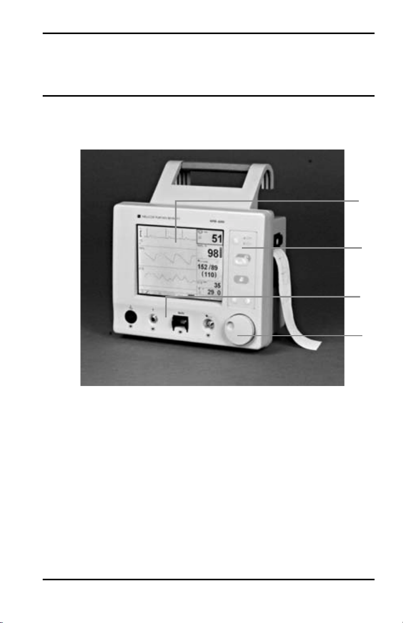
See Figure 1. The front panel controls and indicators are
arranged in groups:
123
1
2
3
4
Figure 1: Front Panel, NPB-4000/C
1. Display: (the major area of the panel)
2. Switch Panel: (to the right of the display)
3. Patient Connectors: (along the bottom of the panel)
4. Control Knob: (the lower right corner of the panel)
7
Page 14
Controls, Indicators, and Symbols
Patient Monitoring Connectors
All patient connections to the NPB-4000/C are classified as type
CF, which specifies their degree of protection against electrical
shock, and all are rated as defibrillator-proof. Consequently,
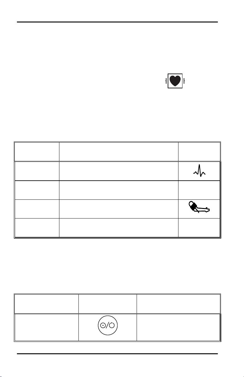
each connector is marked with the following symbol.
Symbol for Defibrillator-proof
Type CF Equipment
A unique icon identifying the parameter being monitored
through that connector identifies each connection. Table 1
defines the monitored parameter, connector compatibility, and
icon.
Table 1: Front Panel Connectors
Monitored
Parameter
ECG
Compatible with Nellcor CE-10 ECG
Cables
SpO
2
Compatible with Nellcor sensors and
sensor extension cables
NIBP
Compatible with Nellcor SHBP-10 blood
pressure hose
Temperature
Compatible with YSI Series 400
temperature probes
Switch Panel
The symbols identifying the switches and light emitting diode
(LED) indicators on the Switch Panel are described in Table 2.
Switched/LED
Descriptor
On/Standby Switch
Connector Compatibility Icon
SpO
2
T
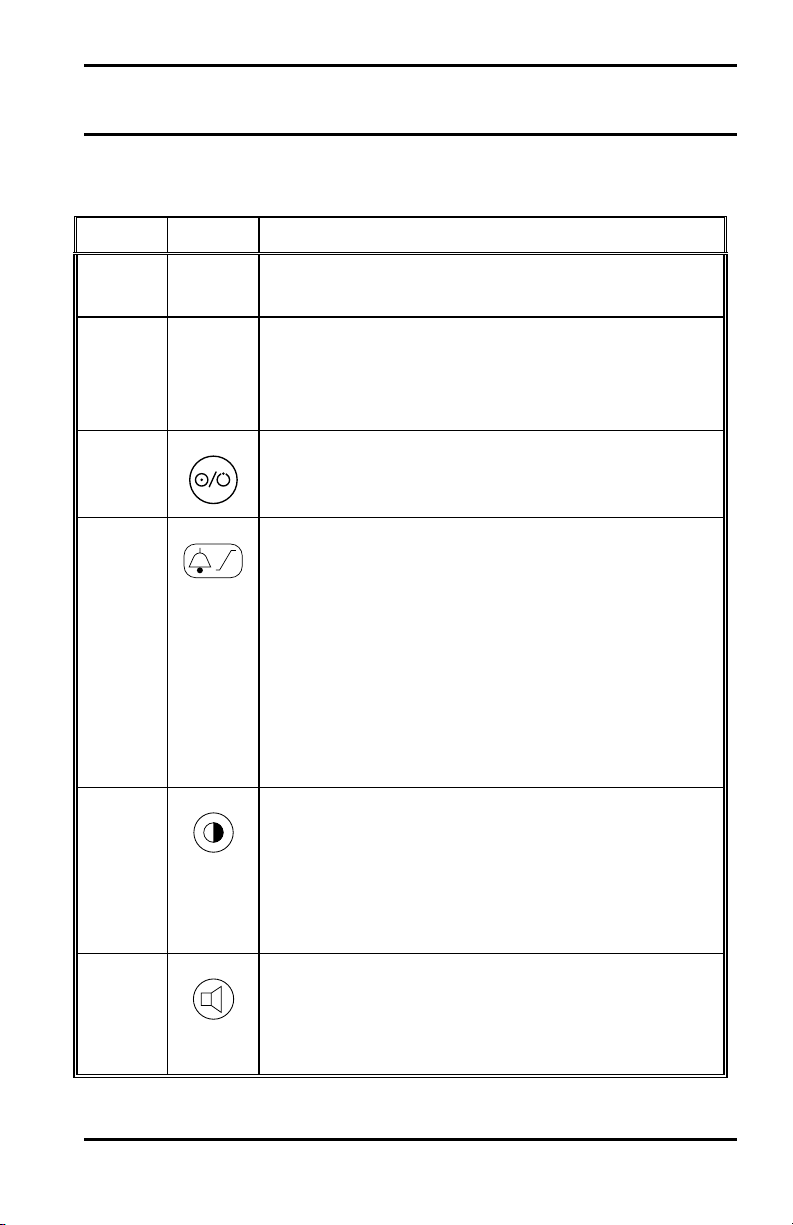
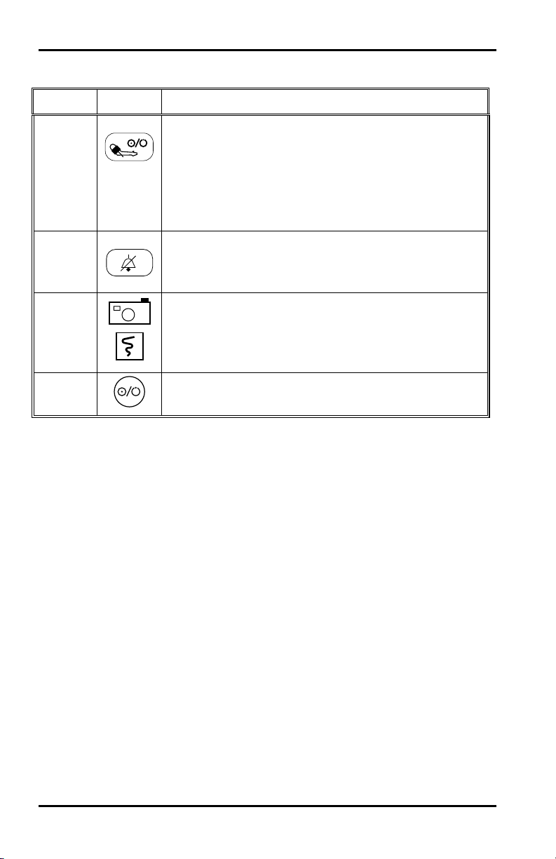
Table 2: Switch Panel Symbols
Icon Operation
Toggles NPB-4000/C
between ON and
STANDBY modes
%
8
Page 15
Controls, Indicators, and Symbols
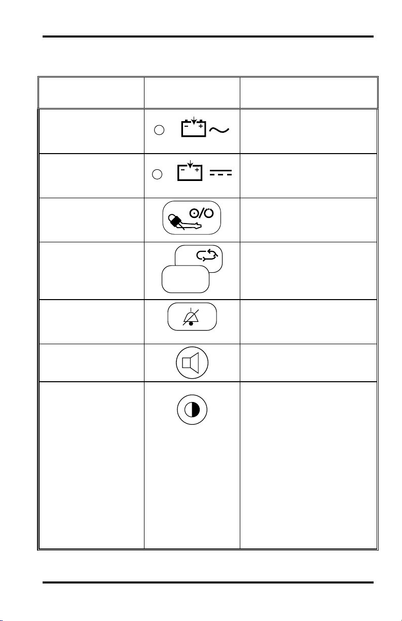
Table 2: Switch Panel Symbols
Switched/LED
Descriptor
AC source LED
Indicator
DC source LED
Indicator
NIBP Start/Stop
Switch
NIBP STAT icon
Alarm Silence
Switch
Heart Rate Tone
Volume Switch
Icon Operation
When lit, indicates an AC
source connected and
charging the battery
When lit, indicates a DC
source connected and
charging the battery
Toggles between starting
and stopping NIBP
measurement
Indicates STAT mode,
which is activated by
pressing and holding the
NIBP switch for 2 seconds
Temporarily silences the
audible alarm sound for a
pre-set interval
Enables the knob to adjust
volume of the audible tone
Contrast Adjust
Switch
NPB-4000 Pressing switch
causes screen contrast to
change to an average
setting. Also enables the
knob to adjust the contrast
of the display.
NPB-4000C Pressing
switch causes the screen to
switch to the alternate set of
colors (black background
vs. white background).
9
Page 16
Controls, Indicators, and Symbols
Display Symbols
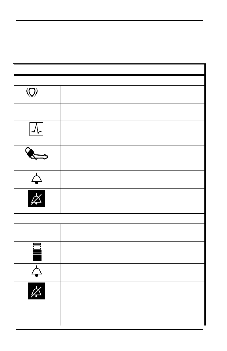
The symbols and icons used in the NPB-4000/C patient monitor
display are described in Table 3.
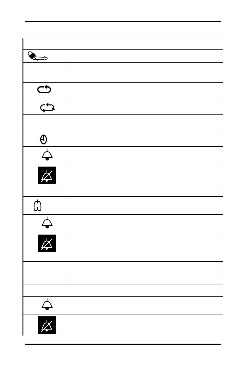
Table 3: Display Symbols
Display - Numeric Frame Symbols
Heart Rate
SpO2
SpO2
SpO
/min
%
%
2
Heart rate icon. Identifies the frame and indicates the
units, beats per second. Always displayed.
Heart rate determined from SpO2 sensor. Displayed
when heart rate is derived from the SpO
Heart rate determined from ECG measurement.
Displayed when heart rate is derived from the ECG
measurement.
Heart rate determined from NIBP measurement.
Displayed when heart rate is derived from the NIBP
measurement.
Heart rate alarm. Displayed when a heart rate alarm
limit has been violated.
Audible Alarm Off. Displayed when audible alarm is
silenced. This icon is in reverse video to indicate that
the audible alarm is temporarily silenced.
SpO2 frame icon. Identifies the frame and indicates
the units (percent). Always displayed.
Pulse amplitude indicator.
sensor.
2
10
SpO2alarm. Displayed when an SpO2 alarm limit has
been violated.
Audible Alarm Off. Displayed when the audible
alarm is silenced. This icon is in reverse video to
indicate that the audible alarm is temporarily silenced.
Page 17
NIBP
Controls, Indicators, and Symbols
Table 3: Display Symbols
mmHg
140/90
(106)
30
180
17
Respiration Rate
/min
NIBP icon and units of measure
Systolic blood pressure/Diastolic blood pressure
(Mean arterial pressure value)
Auto mode icon and minutes between automatic NIBP
measurement
STAT mode icon appears when STAT mode is active
Display of the initial cuff pressure to be used on the
next measurement.
Timer icon and minutes since last NIBP measurement
NIBP alarm. Displayed when an NIBP alarm limit has
been violated.
Audible Alarm Off. Displayed when audible alarm is
silenced
Respiration icon and units of measure
Respiration alarm. Displayed when a respiration rate
alarm limit has been violated.
Temperature
T
C
Audible Alarm Off. Displayed when audible alarm is
silenced
Temperature icon
Temperature unit of measure, ° C or ° F
Temperature alarm. Displayed when a temperature
alarm limit has been violated.
Audible Alarm Off. Displayed when audible alarm is
silenced.
11
Page 18
Controls, Indicators, and Symbols
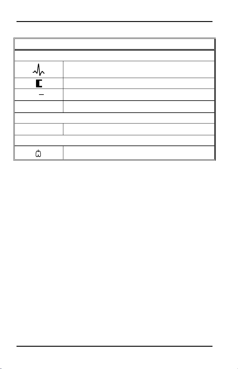
Table 3: Display Symbols
Display - Graphic Frame Symbols
ECG Waveform
ECG icon
Size bar, 1 cm high
mV
0.5
cm
Size scale
II
Lead pair
SpO2 Waveform
SpO
%
2
SpO2 icon
Respiration Waveform
( )
Respiration icon
12
Page 19
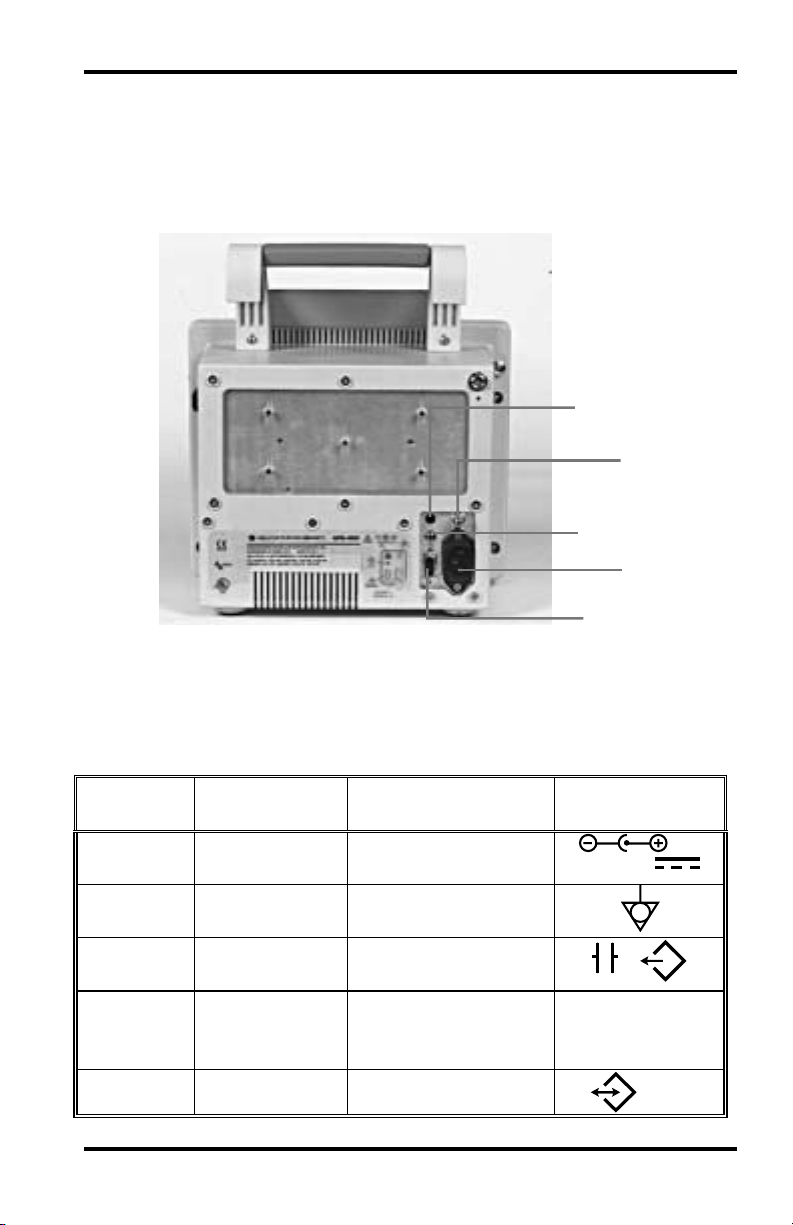
REAR PANEL
Five connectors are located on the rear panel of NPB-4000/C.
See Figure 2 and refer to Table 4. The rear panel includes
threaded standoffs for attaching a GCX mounting system
accessory.
Controls, Indicators, and Symbols
1
2
3
4
5
Figure 2
Description Connector Type Icon
Callout
1 DC Input
2 Equipotential
3 Defib Sync
4 AC Input
5 RS-232 I/O
Figure 2: Rear Panel, NPB-4000/C
Table 4: Rear Panel Connectors
2-line; + and ground
Equipotential
ground
2.5 mm subminature
phone jack
3-line connector,
100 - 240V ~
IEC 320 receptacle
DB-9 (male)
10 - 16V
5A
50 - 60 Hz
1 A
RS-232
13
Page 20

[THIS PAGE INTENTIONALLY LEFT BLANK]
Page 21
QUICK GUIDE TO OPERATION
Table 5: Quick Guide Procedure
Step Icon Operation
1 … Connect patient cables to front panel connectors
(refer to Setup & Use, page21).
2 … As appropriate, attach cuff, sensor, electrodes,
probe to patient and cables to the monitor (refer
to Monitoring sections pages 55, 65, 73, 83 and
89).
3 Press On/Standby switch to turn monitor on. The
NPB-4000/C will go through a self-test before
displaying the monitoring screen.
4 Check the alarm limits; adjust if required. Rotate
the knob to highlight the Alarm Limits icon, then
press the knob to view all alarm limits. To
change a limit, rotate the knob until the desired
limit is highlighted, then press the knob. Rotate
the knob again until desired value is obtained.
Repeat as necessary. Upon completion, rotate the
knob to highlight Return, then press the knob to
exit the monitoring screen (refer to Alarms &
Limits, page 41).
—
— To adjust the heart rate tone volume, press the
NPB-4000 To adjust the screen contrast, press
the Contrast Adjust switch and rotate the knob to
give the best viewing angle.
NPB-4000C To adjust color set, press the
Contrast switch until the screen provides an
optimum contrast in the intended setting.
Heart Rate Tone Volume switch and rotate the
knob to give the desired volume.
15
Page 22
Quick Guide to Operation
Table 5: Quick Guide Procedure
Step Icon Operation
— To initiate a blood pressure measurement, press
the NIBP Start/Stop switch. Press and hold the
NIBP Start/Stop switch for 2 seconds to initiate
STAT mode. A press during any measurement
terminates the measurement and deflates the cuff
(refer to NIBP Monitoring, page 65).
— To temporarily silence an audible alarm, press the
Alarm Silence switch (refer to Alarms & Limits,
page 41).
— To produce a 20-second printout (if optional
printer installed), press Snapshot switch on the
printer. Press the Continuous switch to produce a
continuous printout (refer to Printing, page 99).
5 Press the On/Standby switch to terminate
monitoring and blank the screen.
16
Page 23
FEATURES
Physical/Mechanical
Electrical
Display
Auxiliary Outputs
Options and Accessories
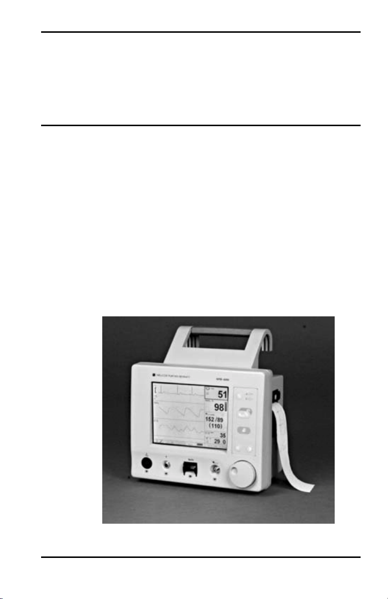
PHYSICAL/MECHANICAL
The NPB-4000/C patient monitor is a lightweight, compact,
multi-parameter patient monitor measuring 10.6 in x 8.6 in x 6.5
in (26.5 cm x 21.8 cm x 16.5 cm) and weighing 10.8 lb (4.9 kg)
without printer, cable, and accessories. Its carrying handle is
designed for instrument transport while battery-powered
monitoring continues.
The optional printer is installed within the case, adding 0.9 lb
(0.4 kg) to the monitor weight.
Mounting attachments are provided on the case for use with an
optional GCX mounting system. Refer to OPTIONAL
ACCESSORIES section, page 123.
Figure 3: NPB-4000/C Patient Monitor
17
Page 24

Features
ELECTRICAL
The NPB-4000 is powered by an internal battery pack that
provides 4 hours of monitoring from fully charged batteries
(typical, performance is at 25º C, with no printing, and one
NIBP measurement every 15 minutes). The batteries are
continuously recharged when AC or DC power is connected to
the monitor.
The NPB-4000C is powered by an internal battery pack that
provides 3 hours of monitoring from fully charged batteries
(typical, performance is at 25º C, with no printing, and one
NIBP measurement every 15 minutes). The batteries are
continuously recharged when AC or DC power is connected to
the monitor.
Battery charging is indicated by front panel green LCDs. Two
LCDs are used, one for AC and one for DC. When operating on
batteries, a battery “gauge” icon in the lower part of the display
indicates the battery charge condition.
A warning message appears on the screen and an audible alarm
sounds when the remaining battery power is only enough for 15
minutes of operation. The user should connect the monitor to an
external power source to avoid loss of patient monitoring action.
External power sources may be connected, disconnected, and
reconnected without interrupting the monitoring action.
DISPLAY
The NPB-4000 monitoring screen is a monochrome LCD display
that shows all graphic and numeric patient information as well
as alphanumeric status conditions and warning messages.
The NPB-4000C monitoring screen is a color LCD that shows
all graphic and numeric patient information as well as
alphanumeric status conditions and warning messages.
The graphics, text, and numeric information are grouped into
areas through which the user interacts to control the monitoring
functions and elements of the screen information.
18
Page 25

Control Knob and Menus
The Control Knob provides user interaction with the display and
the monitor functions.
Features
Rotating and pressing the knob
allows a user to navigate and
make changes to the display
elements and monitor
functions. Details of this
interactive operation are
described in the Display &
Operation section, page 29.
AUXILIARY OUTPUTS
The NPB-4000/C monitor exports trend data via an RS-232 I/O
port. The port also provides the capability for initiating a Nurse
Call upon alarm. Refer to the RS-232 INTERFACE section,
page117, for additional information.
The monitor generates a defibrillator synchronization signal,
Defib Sync. The Defib Sync signal is available at the monitor
rear panel. Refer to the DEFIB SYNC OUTPUT section, page
122.
OPTIONS AND ACCESSORIES
Refer to the OPTIONAL ACCESSORIES section, page 123,
for descriptions of the monitor’s options and accessories.
Rotate
Press
19
Page 26

[THIS PAGE INTENTIONALLY LEFT BLANK]
Page 27

SETUP and USE
Unpacking and Inspection
Power Cable Connections
Measurement Cable Connections
Power On and Self Test
WARNING: The NPB-4000/C is a prescription device and is
to be operated by qualified personnel only.
WARNING: In the USA, do not connect to an electrical
outlet controlled by a wall switch because the device may be
accidentally turned off.
WARNING: As with all medical equipment, carefully route
patient cabling to reduce the possibility of patient
entanglement or strangulation.
WARNING: Do not use the NPB-4000/C patient monitor to
monitor neonates.
CAUTION: If the NPB-4000/C is to be stored for a period of
2 months or longer, notify service personnel to remove the
battery from the monitor prior to storage. Recharge the
battery when the battery has not been recharged for 2 or
more months.
CAUTION: Follow local government ordinances and
recycle instructions regarding disposal or recycling of device
components, including batteries.
UNPACKING AND INSPECTION
The NPB-4000/C patient monitor is shipped in one carton.
Examine the carton carefully for evidence of damage. Contact
the carrier immediately if any damage is discovered.
Retain all packing material. Refer to the Operator
Maintenance and Troubleshooting section, page 103, for
instructions on returning damaged items.
21
Page 28

Setup and Use
POWER CABLE CONNECTIONS
AC Power
Ensure that the AC outlet is properly grounded and of the
specified voltage and frequency (100-240 VAC, 50-60 Hz).
Connect the AC power cord to the monitor rear panel connector
identified with the AC power icon. See Figure 2, page 13. Use
only a Nellcor supplied power cord. If in doubt about the
integrity of the grounding of the AC power source, the monitor
must be operated from its internal battery.
DC Power
Connect an external DC power source (10 to 16 volts DC) to the
monitor rear panel connector identified with the DC power icon.
See Figure 2, page 13. Use only a Nellcor DC input cable. The
user must ensure that connection to the external DC supply
meets all applicable safety codes.
MEASUREMENT CABLE CONNECTIONS
WARNING: Do not lift the monitor by the sensor cables,
blood pressure hose, or power cord because the cable, lead,
or cord could disconnect from the monitor, causing the
monitor to drop on the patient.
ECG Cable and Leads
Use only a Nellcor CE-10 ECG cable and LE-Series ECG leads
with the NPB-4000/C or, or an ECG cable and leads
recommended by Nellcor Technical Services.
Connect the cable to the front panel connector marked with the
ECG icon. See Figure 1, page 7, and refer to Table 1, page 8.
Connect leads to the patient as described in the ECG
Monitoring section, page 55.
22
Page 29

NIBP Hose and Cuff
Use only a Nellcor SHBP series hose and SCBP-Series cuff with
the NPB-4000/C, or a hose and cuff recommended by Nellcor
Technical Services.
Refer to the NIBP Monitoring section, page 65. Select the
appropriate size cuff for the patient. Apply the cuff to the
selected limb. Connect the hose to the front panel connector
marked with the NIBP icon. See Figure 1, page 7, and refer to
Table 1, page 8.
SpO2 Cable and Sensor
Use only Nellcor sensor extension cables and SpO2 sensors with
the NPB-4000/C.
Setup and Use
Refer to the SpO
appropriate sensor for the patient and desired application. Apply
the sensor to the selected site. Connect the sensor to the cable,
and connect the cable to the front panel connector identified
with the SpO
page 8.
Temperature Probe
The monitor uses YSI Series 400-compatible temperature
probes. Insert the plug into the compatible jack on the monitor
front panel marked with the temperature icon. See Figure 1,
page 7, and refer to Table 1, page 8. Refer to Temperature
Monitoring section, page 115 for details.
2 Monitoring section, page 73. Select an
icon. See Figure 1, page 7, and refer to Table 1,
2
23
Page 30

Setup and Use
POWER ON AND SELF-TEST
WARNING: If you do not hear the POST (power on
self-test) pass tone, do not use the monitor.
WARNING: Disconnect the NPB-4000/C and sensors
during magnetic resonance imaging (MRI) scanning. Use
during MRI may cause burns or adversely affect the MRI
image or the monitor’s accuracy
CAUTION: If any indicator or display element does not
light, do not use the monitor. Instead, contact qualified
service personnel, your local Nellcor representative, or the
Nellcor’s Technical Services Department.
Note: The battery may be discharged upon receipt. It will be
fully charged after the first 8 hours the monitor is
connected to an AC or DC power source.
Internal batteries that are charged by NPB-4000/C connection to
external AC or DC sources supply the monitor power. The front
panel display indicates the status of external power sources, as
summarized in Table 6.
24
Table 6: Battery Charging Front Panel Indications
External Power
Front panel Indications
Connections
AC source AC icon lighted
DC source DC icon lighted
None Battery “gauge” appears in display.
No LED lit
After patient sensors are connected to their input cables, turn the
monitor ON by pressure the front panel On/Standby switch.
Audible feedback after pressing a front panel switch indicates
that the monitor is processing the action.
Page 31

Setup and Use
A copyright screen appears while the NPB-4000/C runs a set of
self-diagnostic test routines. See Figure 4. The copyright screen
displays the version of software installed in your unit. Call
Nellcor’s Technical Services for the latest applicable software
and to inquire about software updates.
Copyright 1998 Analogic Corporation. All rights reserved.
V 3.00
Figure 4: Copyright Screen
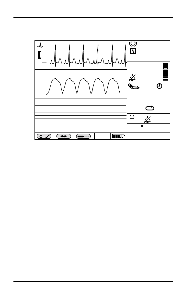
After power-up diagnostics are completed successfully, the
NPB-4000/C initiates monitoring operation. If no leads have
been connected to the patient, the display appears similar to that
shown in Figure 5.
/min
mV
0.5
cm
II
SpO2
( )
NIBP Ð Blocked Hose
x
X
Adult 2/14/95 16:34:36
SpO2
( )
T
%
mmHg
( )
/min
C
Figure 5: Typical Screen for No Patient Leads
/
180
25
Page 32
Setup and Use
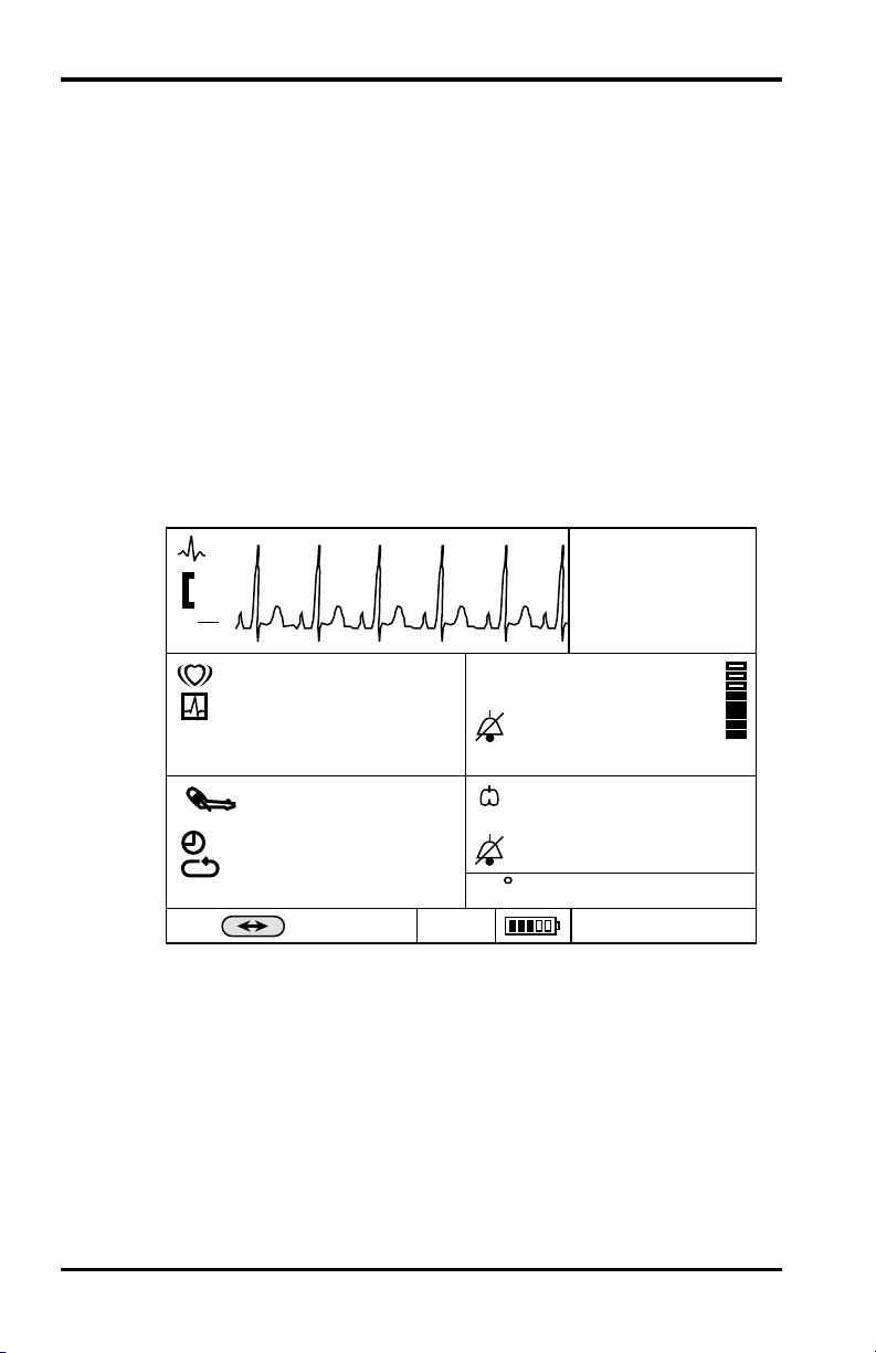
When the monitor detects valid signals a typical presentation
with two real-time waveforms and a tabular trend appears. See
Figure 6.
/min
0.5
II
SpO
mV
cm
2
SpO
85
%
2
97
mmHg
TREND - 2/14
Figure 6: Typical Screen, Valid Monitored Signals
( )
NIBP HB SpO2 RR TTime
140/90(97) 82 95 11 37.616:17:05
x
X
Adult 2/14/95 16:34:36
If the ON/Standby switch is pressed when in the monitoring
mode, the monitor is placed in the Standby mode, in which:
• The display is blanked
• Trend data taken during the monitoring mode
remains stored in memory
• No further monitoring takes place
• Battery charging continues if the monitor is
connected to an AC or DC power source
/min
T
140/90
(106)
30
C
37.8
17
180
14
SET DATE AND TIME
This procedure will enable you to set the date and time displayed
on the screen and printed on the reports. Setting the date and
time is accomplished by rotating and pressing the control knob.
Note: Read all procedure steps before trying to make any
changes. The display will return to the normal display
screen if the knob is not rotated or pressed for 20
seconds.
26
Page 33

Setup and Use
1. Rotate the knob to highlight the date time box. A dark
border appears around the frame.
2. Press the knob. Date/Time menu appears.
3. Rotate the knob to highlight Date Format.
4. Press the knob. The date formats appear.
5. Rotate the knob to highlight: mm/dd/yy or dd/mm/yy.
6. Press the knob. The highlighted format appears after the
Date Format menu entry.
7. Rotate the knob to highlight Set Date.
8. Press the knob. A date appears.
9. Rotate the knob to highlight the section of the date to be
changed.
10. Press the knob. Selects the parameter to be changed.
11. Rotate the knob until the desired number is displayed.
12. Press the knob. The desired number is entered into the
monitor.
13. Repeat steps 9 through 12 until the desired date is entered.
14. Rotate the knob to highlight Return.
15. Press the knob. The display returns to the Date/Time menu.
16. Rotate the knob to highlight Set Time.
17. Press the knob. A time appears.
18. Rotate the knob to highlight the section of the time to be
changed.
19. Press the knob. Selects the parameter to be changed.
20. Rotate the knob until the desired number is displayed.
21. Press the knob. The desired number is entered into the
monitor.
22. Repeat steps 18 through 21 until the desired time is entered.
23. Rotate the knob to highlight Return.
24. Press the knob. The display returns to the Date/Time menu.
25. Rotate the knob to highlight Return.
26. Press the knob. The display returns to the normal
monitoring screen.
27
Page 34

[THIS PAGE INTENTIONALLY LEFT BLANK]
Page 35

DISPLAY and OPERATION
The Display Configuration
Controlling Monitor Operation and Display Elements
WARNING: The NPB-4000/C is intended only as an
adjunct in patient assessment. It must be used in
conjunction with clinical signs and symptoms.
WARNING: Each time the monitor is used, check alarm
limits to ensure that they are appropriate for the patient
being monitored.
WARNING: The nurse call feature should not be used as
the primary source of alarm notification. The audible and
visual alarms of the monitor, used in conjunction with
clinical signs and symptoms, are the primary source for
notifying medical personnel that an alarm condition exists.
THE DISPLAY CONFIGURATION
General
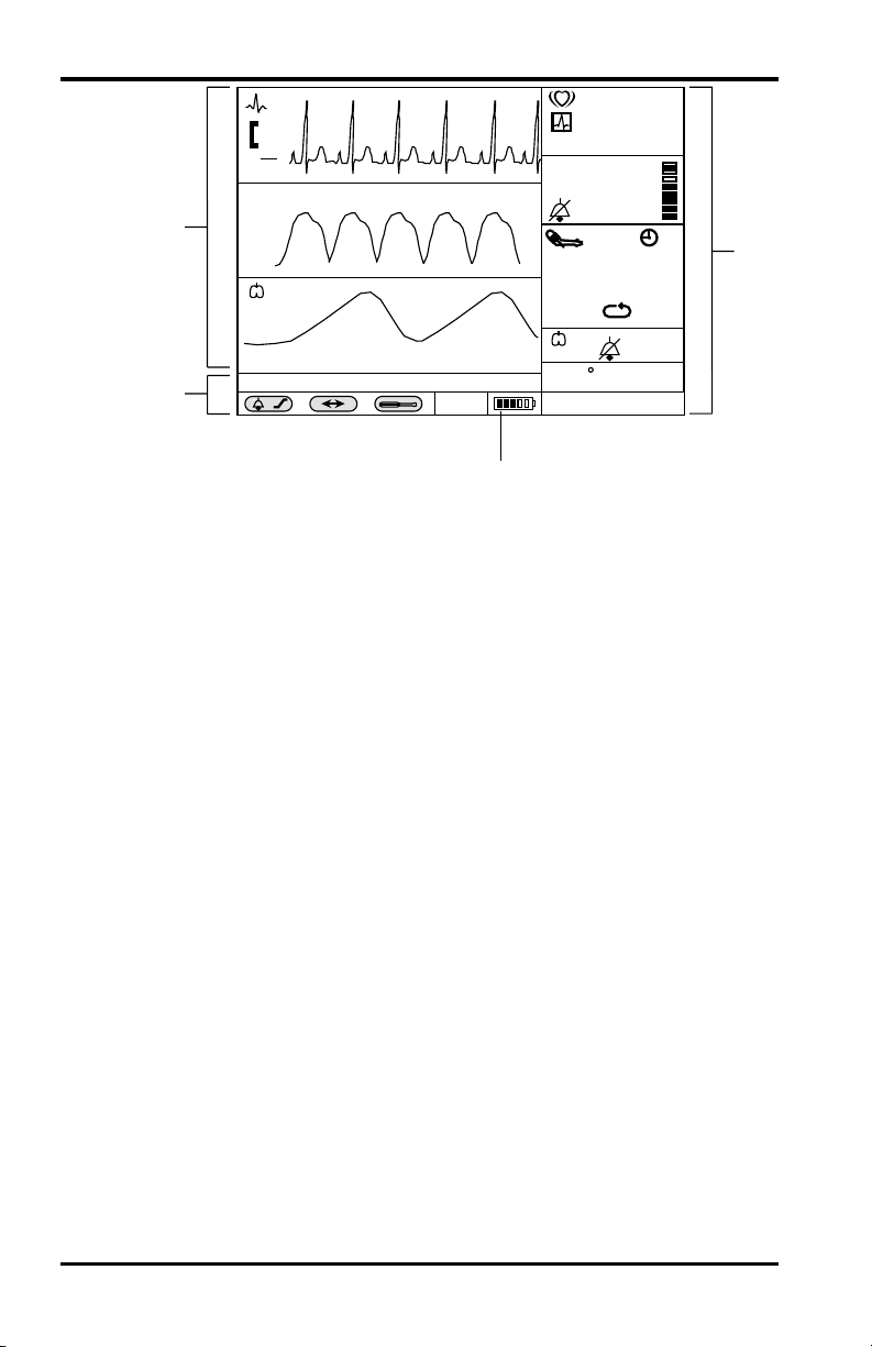
The display in Figure 7, page 30, is of a typical monitoring
condition with three waveforms. The display is divided into a
number of areas that are further subdivided into frames.
29
Page 36
Display and Operation
/min
4
3
Color Display
The NPB-4000C patient monitor has a color liquid crystal
display (LCD). The NPB-4000C LCD performs the same
functions as the NPB-4000 LCD except that the display is in
color. The colors are function related as shown in Table 7, page
31.
0.5
SpO
mV
cm
II
2
SpO
85
%
2
97
180
30
14
37.8
17
mmHg
140/90
( )
NIBP - Blocked Hose
x
X
Adult 2/14/95 16:34:36
(106)
/min
C
T
2
Figure 7: A Typical Monitoring Screen
1. Numeric Area
2. Gauge Indicates Monitor is Using Only Battery
3. Message/menu area
4. Graphic Area
1
30
Note: The Contrast Adjust switch is implemented differently on
the NPB-4000 and the NPB-4000C. See Table 2, page 8.
Page 37

Table 7: NPB-4000C Color Description
Function Color
ECG/Heart Rate Green
Display and Operation
SpO
2
NIBP Red
Respiratory Yellow
Temperature Orange
General Background Black or white
Medium Priority Alarm Flash Yellow (numeric
High Priority Alarm Flash Red (numeric
Battery Icon (normal) Green
Battery Icon (low battery) Yellow or Red (refer to
Numeric Area/Frames
The right-hand area of the display is the numeric area and
contains six frames in which numeric values are displayed. Five
of the frames contain suitable icons relating the values to
monitored patient parameters; the sixth frame displays time and
date.
Blue
depending on the color
set selected by the
Contrast Adjust switch.
frame background)
frame background)
Table 8, page 33)
Numeric Frames
From top to bottom, the six numeric frames display the
following:
• Heart Rate in beats/minute
• SpO
• NIBP Systolic/Diastolic (Mean Arterial Pressure) in mmHg
• Respiration Rate in breaths/minute
in percent saturation
2
31
Page 38

Display and Operation
• Temperature in ° C or ° F
• Date and Time: mm/dd/yy or dd/mm/yy for date, and
24-hour format for time
The numeric frames always represent the icon-indicated vital
signs and may not be reassigned, resized, or resequenced.
Graphics Area/Frames
The upper left area is called the graphics area and it contains
three equally sized graphics frames in which real-time
physiological waveforms, graphical trend, or tabular trend data
are displayed.
When the ECG leads are connected to the patient, the top
graphics frame always displays the ECG waveform. In the
remaining two graphic frames, the user may select available
waveforms or trend. The waveforms or trends appearing in the
frames at power-up are factory set, but may be changed by
qualified service personnel with passcode access.
When a menu setup is selected, a single menu frame in which
submenus and selectable parameter values are displayed for user
selection replaces the lower two graphics frames.
Message/Menu Frames
The area below the graphics area is called the Message/Menu
area. The upper of two frames in this area is reserved for
messages. These are in simple language and describe alarm
conditions. The message remains displayed until the problem is
resolved, or it may be cleared by pressing the front panel Alarm
Silence switch. If there is more than one message, each is
displayed for 1 second.
The lower of the two sets of frames in this area is used to show
status icons and to provide menu choices.
32
Page 39

Status Icons
Battery Icon:
Display and Operation
The Battery-in-Use icon (at the right end of the frames)
appears whenever the monitor is operating on battery power
alone. The icon is in the form of a “gauge” providing a
graphic indication of remaining battery power. In the NPB4000, the icon flashes when the monitor detects low battery
power. In the NPB-4000C, the icon is displayed as
indicated in Table 8.
Table 8: NPB-4000C Battery Icon
Operating Mode:
Menu Icons
There are three icons in the Menu portion of the Message/Menu
area: Alarm/Limits, Big Numbers, and Setup.
Alarm/Limits Icon:
Number of Bars
Color Used Behavior
Illuminated
3, 4, or 5 Green Constant display
2 Yellow Constant display
1 Red Constant display
0 Red Icon flashes and
message displayed
The operating mode “Adult” is indicated at the left of the
battery gauge. The Adult operating mode accommodates
both adult and pediatric patients.
When selected, a menu appears in Frames 2 and 3 of the
Graphics Area. The user may view the current alarm limit
settings, or may modify them.
33
Page 40
Display and Operation
Big Numbers Icon:
When selected, a Big Numbers display format is generated,
and five numeric frames of monitored patient vital signs are
enlarged and replace the lower two graphic frames and the
six numeric frames. See Figure 8. The time value is moved
to the upper right of the screen.
Setup Icon:
When selected, a menu of general-purpose parameters is
presented in the graphics area. The user activated Nurse
Call signal, if connected. Qualified service personnel can
change the Power-Up Default settings of the monitor by
using the Enter Power-Up Default Menu. This function is
passcode protected, and is further described in Power-Up
Default Settings section, page 35.
mV
0.5
cm
II
/min
SpO
16:34
2
%
mmHg
17
30
x
Big Numbers Screen
The Big Numbers screen provides numeric values that can be
read at a distance, and may be more useful to the clinician. Use
of the Big Numbers presentation has the following
characteristics.
34
85
/min
( )
140/90
(106)
180
X
Figure 8: Big Numbers Screen
Adult
C
T
97
14
37.8
Page 41

• Selecting the “Big Numbers” icon from the
monitoring screen makes access to Big Numbers;
Big Numbers is not a power-up default choice.
• One press or rotation of the knob causes the
NPB-4000/C to revert to the monitoring screen.
• Any alarm condition causes the NPB-4000/C to
revert to the monitoring screen.
• No changes to the display are possible.
• The top graphic frame remains identical in size and
content, whether in normal monitoring screen or Big
Numbers screen.
• Single-function buttons in the switch panel operate
normally, with one exception: if Alarm Suspend is
invoked, the normal monitoring screen immediately
replaces Big Numbers.
Power-Up Default Settings
Each time the NPB-4000/C is turned on, a number of settings are
automatically configured. These settings include alarm limits,
ECG lead selection, type of waveforms and/or trends presented
in the graphic frames, heart rate tone source, and others. These
settings are known as power-up defaults. Each power-up default
is set at the factory; however, qualified service personnel may
change the factory-set defaults. Instructions for making these
adjustments are found in the NPB-4000/C service manual.
Display and Operation
CONTROLLING MONITOR OPERATION AND DISPLAY ELEMENTS
Except for actions initiated by pressing a front panel switch,
control of the NPB-4000/C patient monitor is accomplished by
using the knob to interact with the appropriate area on the
display.
The procedure is the same for all operational and display
changes:
1. Rotate the knob to highlight item to be changed.
35
Page 42

Display and Operation
2. Press the knob to make the change
The monitoring screen is, in effect,
a high-level menu. Highlighting an
area on the monitoring screen by
rotating the knob, and selecting it
by pressing the knob, will bring up
a Level 1 menu that relates to that
screen area. Once in the Level 1
menu, the same action-pair of
rotating and pressing the knob to
highlight and select a menu item
takes place. The response may be
effective immediately or may bring
up a Level 2 menu that “pops up”
on the screen without removing the
Level 1 menu.
A knob time-out of 20 seconds (no knob action) returns the
display to the monitoring screen.
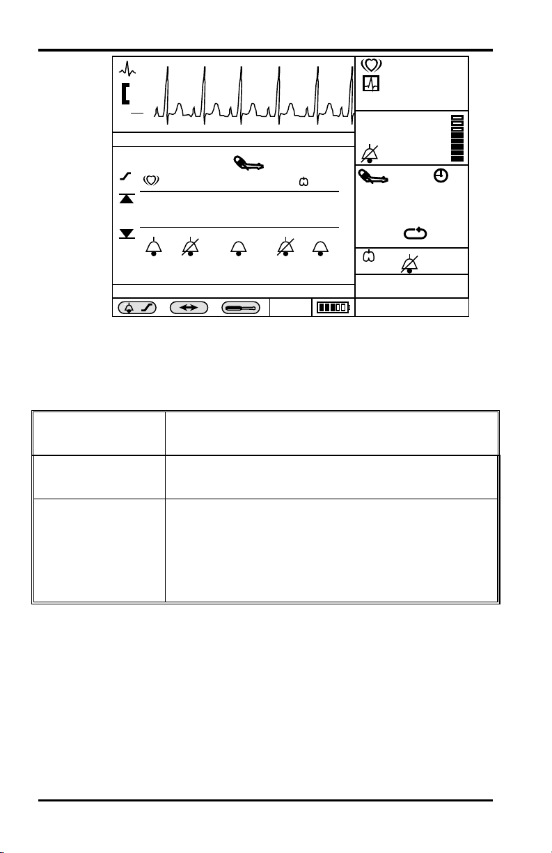
Example of a Change Operation
To change the sweep speed of the ECG waveform presented in
the top graphics frame:
1. ROTATE the knob to highlight the ECG graphics frame. A
dark border appears around that frame.
Rotate
Press
36
2. PRESS the knob. The Level 1 menu appears.
3. ROTATE the knob to highlight Sweep Speed. It appears in
reverse video.
4. PRESS the knob. A Level 2 menu appears, and the current
value is highlighted in reverse video.
5. ROTATE the knob to highlight a different value in the list.
6. PRESS the knob. The waveform speed is changed to the
new sweep speed.
7. ROTATE the knob to highlight Return.
8. PRESS the knob to return to the normal monitoring screen.
Figure 9, page 37, illustrates the process described above.
Page 43

Display and Operation
1
5
/min
mV
0.5
cm
II
ECG WA VEFORM MENU
Lead Select (II)
4
3
2
Sweep Speed (25 mm/s)
Size (0.5 Mv/cm)
Pacer Detect (Off)
Extended Low Frequeny Range (Off)
ECG Waveform
SpO2 Waveform
Respiration Waveform
Tabular Trend
HR Graphical Trend
SpO2 Graphical Trend
NIBP Grapical Trend
RR Graphical Trend
Temperature Graphical Trend
Return
x
X
12.5 mm/s
25 mm/s
50 mm/s
Adult 2/14/95 16:34:36
Figure 9: Highlighted ECG Graphic;
Level 1 and Level 2 Menus
1. Level 2 Menu
4. Level 1 Menu
Graphic Type
2. Closes Menu 5. Highlighted and Selected ECG
Waveform
3. List of Other Graphic
Types
Items
%
SpO
2
97
mmHg
140/90
(106)
/min
C
T
for Current
85
180
30
14
37.8
17
Note: Although other graphic types are listed as possible menu
choices for the top graphics frame, they are not available
when the ECG cable is connected. If an attempt is made
to select another graphic waveform, the following
message block appears “Selection not available.”
Cascading Waveforms
If a waveform already displayed in a graphics frame is also
selected for another frame, then the two frames form a cascaded
waveform, effectively presenting a sample over twice the time
interval of one frame.
The second half of the cascade may be in any frame, and need
not be placed directly under the first frame.
37
Page 44

Display and Operation
Change Operations Described in Tables
Figure 10 shows an expanded view of a SpO2 waveform frame.
To make a change to this waveform, or put a different type of
graphic in its place, rotate the knob until the SpO
frame is highlighted, then press the knob. The relevant menu
appears in the second and third graphic frames.
waveform
2
Table 9, page 39 details the SpO
mV
0.5
cm
II
SpO2
( )
x
X
Figure 10: SpO2 Screen
2
SpO
2
1. SpO
2. SpO
( )
NIBP Ð Blocked Hose
Waveform
2
Icon
2
waveform menu.
2
/min
85
%
SpO
2
97
mmHg
140/90
(106)
30
/min
C
T
Adult 2/14/95 16:34:36
37.8
17
180
14
1
38
Page 45

Display and Operation
Table 9: SpO2 Screen Menus
Level 1 Menu Screen Level 2 Menu or Response
Title: SpO2 WAVEFORM MENU
Sweep Speed 12.5 mm/s, 25 mm/s, 50 mm/s
Other graphic type choices:
ECG Waveform
Waveform
2
>SpO
Respiration Waveform
Tabular Trend
HR Graphical Trend
SpO
Graphical Trend
2
NIBP Graphical Trend
Temperature Graphical
Trend
Return
In this example, the only variable setting for the SpO2 waveform
is Sweep Speed.
Other graphic types may be selected, as listed. An arrow
indicates the current graphic type. The list is the same for all
graphic menus.
The final selection is Return to monitoring screens.
In this example, there is only one variable parameter (sweep
speed. The possible sweep speeds are 12.5, 25, or 50 mm/s.
Note: Table 9, page 39, incorporates a type-font convention to
distinguish what appears on the screen and any
descriptive phrase for segments of the information. The
screen text is presented in bold font; the descriptive text
is in Italics or regular font.
No Level 2 menu for these items;
selection of a new graphic type
immediately causes the title and the first
menu items to update to reflect the new
choice.
Exits Level 1 menu immediately,
returns to Monitoring Screen
This presentation of the screen frame and the associated tables
of menu choices will be used throughout this manual to
summarize the monitoring operations and screen presentations.
39
Page 46

[THIS PAGE INTENTIONALLY LEFT BLANK]
Page 47

ALARMS and LIMITS
General
Alarm Priority
Loss-of-Monitoring Alarm
Visual Alarm Indicators
Audible Alarm Indicators
Setting and Changing Alarm Limits
Using the Alarm/Limits Screen
Auto-Set Alarm Limits
Using the Numeric Frame
Alarm Limits and Factory-Set Default Values
Alarm Silence Switch
Alarm Suspend
GENERAL
WARNING: Do not silence the audible alarm or decrease its
volume if patient safety could be compromised.
WARNING: Each time the monitor is used, check alarm
limits to ensure that they are appropriate for the patient
being monitored.
WARNING: The nurse call feature should not be used as
the primary source of alarm notification. The audible and
visual alarms on the monitor, used in conjunction with
clinical signs and symptoms, are the primary source for
notifying medical personnel that an alarm condition exists.
When the monitor detects certain conditions that require user
attention, the NPB-4000/C monitor enters an alarm state. The
monitor response is indicated by:
• Visual alarm indicators
• Audible alarm indicators
• Print-on-alarm (if printer installed)
• Identification of out-of-limit vital signs in trend data
• Nurse-call signal (if connected and enabled)
41
Page 48

Alarms and Limits
ALARM PRIORITY
The monitor’s visual and audible responses to a detected alarm
depend on the priority of the alarm; High, Medium, or Low.
A higher priority alarm will supersede a lower priority alarm.
The three categories of alarms are summarized in the following
paragraphs. The text in bold font indicates the message shown
on the screen. Limit alarms do not have messages.
High Priority:
Asystole (4 seconds have passed with no heart beats from
ECG, preceded by detecting valid ECG-derived heart rate
data.)
Loss of Pulse from SpO
Medium Priority:
High/Low Heart Rate limits violated
High/Low SpO
High/Low Sys./Dia./MAP blood pressure limits violated
High/Low Respiration Rate limits violated
High/Low Temperature limits violated
Loss of Respiration Signal
Low Priority:
ECG Leads Off
Cable/Sensor Disconnect
SpO
2
Loss of Pulse from SpO
Low Battery (alarm commences when the NPB-4000/C has at
least 15 minutes of operating time remaining)
Temperature Probe Disconnect
NIBP - No Cuff
NIBP - Blocked Hose
2 (and no valid ECG)
limits violated
2
2 (but there is valid ECG)
42
NIBP - Artifact
NIBP - Time-Out
Printer Out of Paper
Page 49

LOSS-OF-MONITORING ALARM
In the event of a high, medium, or low level alarm, the
NPB-4000/C continues to perform monitoring functions. The
alarms are designed to alert users of patient or instrument
conditions that warrant immediate attention.
A special class of alarms, loss-of-monitoring, occurs when the
NPB-4000/C cannot continue to monitor because of an error
condition or shutdown because of a low-battery condition.
When a loss-of-monitoring alarm occurs, the NPB-4000/C emits
a continuous tone until the Alarm Silence switch is pressed.
WARNING: Neither the print-on-alarm nor the nurse-call
signal will be initiated when the monitor detects a loss-ofmonitoring state.
VISUAL ALARM INDICATORS
When an alarm occurs, the NPB-4000/C responds with visual
alarm indications. The flashing rates for the three categories of
alarms are shown in Table 10. The NPB-4000C alarms use
flashing colors to indicate high and medium priority alarm.
Refer to Table 7, page 31.
Alarms and Limits
Table 10: Visual Alarm Flashing Rates
Alarm Category Flashing Rate
High Priority Two flashes in 1 second
Medium priority One flash in 2 seconds
Low priority Constant (on) (non-flashing)
When a low priority alarm occurs, a non-flashing alarm message
appears in the message area. If more than one low priority alarm
is present, the alarm messages “rotate”. On the NPB-4000C, the
numeric frame background color will change to a solid yellow
for a low priority alarm.
43
Page 50

Alarms and Limits
When a medium priority alarm is activated because a parameter
is outside its alarm limits, the out-of-limit numeric value and the
bell icon in the corresponding Numeric Frame flash at the
medium priority rate. Only the numeric frame background color
will flash yellow for a medium priority alarm in the NPB-4000C.
When the high-priority Asystole alarm occurs, the heart rate
numeric value and the corresponding bell icon flash at the high
priority rate. Only the numeric frame background color will
flash red for a high priority alarm in the NPB-4000C. A nonflashing Asystole message appears in the message area and will
override any other messages which may be present (there is no
message “rotation” in this instance).
When the high-priority loss of pulse from SpO
ECG) alarm occurs, the SpO
(which are “0”) and the corresponding bell icons flash at the
high priority rate. Only the numeric frame background color
will flash red for a high priority alarm in the NPB-4000C. A
non-flashing Loss of Pulse from SpO
message area and will override any other messages that may be
present (there is no message “rotation” in this instance).
AUDIBLE ALARM INDICATORS
The audible alarm has different tone pitch and on-off beep
patterns for each alarm priority. Refer to Table 11.
Table 11: Audible Alarm Characteristics
Alarm Category Tone Pitch Beep Rate
High priority ~930 Hz ~ 3 beeps per sec.
Medium priority ~750 Hz ~ 1 beep per sec.
Low priority ~500 Hz ~ 1beep per 4 sec.
Loss-of-monitoring ~3300 Hz continuous
Note: Visual alarm indicators cannot be suspended or removed.
Audible alarms may be decreased in volume or silenced
as described in the operational instructions that follow.
(with no valid
2
and heart rate numeric values
2
message appears in the
2
44
WARNING: Do not silence the audible alarm or decrease its
volume if patient safety could be compromised.
Page 51

SETTING AND CHANGING ALARM LIMITS
When the NPB-4000/C is first turned on, alarm limits are set to
the power-up default values. Qualified service personnel can
change power-up default alarm limits, as described in the
NPB-4000/C service manual.
The user can change alarm limits from default values, if
necessary, as described below. These changes made by the user
will remain in effect until they are modified again, or until the
NPB-4000/C is turned off.
WARNING: Each time the monitor is used, check alarm
limits to ensure that they are appropriate for the patient
being monitored.
Alarm limits may be set in two ways:
• Via interaction with a numeric frame that presents
currently measured values of a vital sign, or
• Via interaction with the Alarm/Limits Screen that
presents the limits in all measured parameters at one
time.
Alarms and Limits
USING THE ALARM/LIMITS SCREEN
Rotate the knob until the Alarm/Limits icon (bell and limits
symbol) in the lower left of the monitor screen is highlighted.
Press the knob. The Alarm/Limits menu is displayed. The
monitor’s alarm limits currently in effect for all monitored
parameters are displayed at one time.
Figure 11, page 46, illustrates a typical Alarm/Limits screen.
45
Page 52
Alarms and Limits
/min
0.5
II
ALARM /LIMITS MENU
Return
Operation of the Alarm/Limits Menu is summarized in Table 12.
Selected Level 1
Item
Return
mV
cm
Print-on-Alarm (On)
/min
150 100 200 150 100 50 38.5
60
Alarm Volume (6) Silence Period (90 s)
2
SYS
SpO
90 130 100 60 5 36.0
x
X
MAP
( )
DIA
Adult 2/14/95 16:34:36
T
SpO2
( )
T
%
97
mmHg
140/90
(106)
/min
C
Figure 11: Alarm/Limits Screen Presentation
Table 12: Alarm/Limits Menu
Level 2 Screen Menu, or
Monitor Response When Selected
Exit menu immediately, returns to Monitoring
Screen
85
180
30
14
37.8
17
Auto-Set Limits Make No Change to Limits: Limits remain for
all parameters as shown.
Auto-Set Now: New limits are calculated
according to formulas described in Table 13, page
50, and replace those on the screen.
46
Page 53

Table 12: Alarm/Limits Menu
Alarms and Limits
Selected Level 1
Item
Level 2 Screen Menu, or
Monitor Response When Selected
Print-on-Alarm On, Off: Optional printer required. Causes a
20-second “snapshot” printout each time a high or
medium priority out-of-limits alarm condition
occurs. The 20 seconds includes the information
from 10 seconds prior to the alarm event.
Out-of-limits values are identified in the printout
by bracketing them between triangular brackets.
An alarm-initiated printout will interrupt any other
snapshot or trend printing that may be in process.
The interrupted printing will not resume after the
alarm-initiated snapshot has been printed.
HR Upper/Lower
Limits
Variable: When selected by rotating the knob to
highlight the desired limit, pressing the knob
enables its subsequent rotation to cycle through
possible limit values that appear in place. Pressing
knob places the displayed limit in effect.
HR Audible
Silence
On/Off: (Bell icon) Toggling action. When OFF
is selected, permanently silences the audible alarm
for HR limit violations. Bell icon is “slashed”
when OFF is selected.
SpO2
Upper/Lower
Limits
SpO2 Audible
Silence
Variable: When selected by rotating knob to
highlight the desired limit, pressing knob enables
its subsequent rotation to cycle through possible
limit values that appear in place. Pressing knob
places the displayed limit.
On/Off: (Bell icon) Toggling action. When Off
is selected, permanently silences the audible alarm
for SpO
limit violations. Bell icon is “slashed”
2
when Off is selected.
47
Page 54

Alarms and Limits
Table 12: Alarm/Limits Menu
Selected Level 1
Item
SYS
Upper/Lower
Limits
DIA
Upper/Lower
Limits
MAP
Upper/Lower
Limits
NIBP Audible
Silence
Level 2 Screen Menu, or
Monitor Response When Selected
Variable: When selected by rotating knob to
highlight the desired limit, pressing knob enables
its subsequent rotation to cycle through possible
limit values that appear in place. Pressing knob
places the displayed limit in effect.
Variable: When selected by rotating knob to
highlight the desired limit, pressing the knob
enables its subsequent rotation to cycle through
possible limit values that appear in place. Pressing
knob places the displayed limit in effect.
Variable: When selected by rotating knob to
highlight the desired limit, pressing the knob
enables its subsequent rotation to cycle through
possible limit values that appear in place. Pressing
knob places the displayed limit in effect.
On/Off: (Bell icon) Toggling action. When OFF
is selected, permanently silences the audible alarm
for NIBP limit violations. Bell icon is “slashed”
when OFF is selected.
RR Upper/Lower
Limits
RR Audible
Silence
48
Variable: When selected by rotating knob to
highlight the desired limit, pressing the knob
enables its subsequent rotation to cycle through
possible limit values that appear in place. Pressing
knob places the displayed limit in effect.
On/Off: (Bell icon) Toggling action. When Off
is selected, permanently silences the audible alarm
for respiration limit violations and loss of
respiration signal alarm. Bell icon is “slashed”
when Off is selected.
Page 55

Table 12: Alarm/Limits Menu
Alarms and Limits
Selected Level 1
Item
Temperature
Upper/Lower
Limits
Variable: When selected by rotating knob to
highlight the desired limit, pressing the knob
enables its subsequent rotation to cycle through
Level 2 Screen Menu, or
Monitor Response When Selected
possible limit values that appear in place. Pressing
knob places the displayed limit in effect.
Temperature
Audible Silence
On/Off: (Bell icon) Toggling action. When Off
is selected, permanently silences the audible alarm
for HR limit violations. Bell icon is “slashed”
when Off is selected.
Alarm Volume 1, 2, 3, 4, 5, 6, 7, 8, 9: Value increases in eight
5 dBA increments from lowest value of 45 dBA in
Step 1 to a maximum of 73 dBA in step 9.
If the Alarm Silence switch on the front panel is
pressed while setting is changed, the alarm will
sound at the volume selected.
Silence Period 30 s, 60 s, 90 s, 120 s: Time is indicated in
seconds.
Pressing the front panel Alarm Silence switch
temporarily silences alarms for the time indicated
in the Silence Period menu item. Alarm state(s) in
effect at the end of the pre-set interval cause the
audible alarm to sound.
Pressing the Alarm Silence switch a second time
(while the silence interval is still in effect) ends the
interval immediately.
On the NPB-4000, silencing audible alarms does
not affect visual alarm indications.
On the NPB-4000C, the visual indication of low
priority alarms is cleared by a single press of the
Alarm Silence switch.
49
Page 56

Alarms and Limits
AUTO-SET ALARM LIMITS
The Auto-Set Limits function allows the user to quickly set
alarm limits based on the patient’s current vital sign values.
When the Auto-Set Limits item is selected from the
Alarm/Limits Menu, the NPB-4000/C takes each currently
measured vital sign and applies a calculated offset to each value
to generate the new upper and lower alarm limits. Refer to
Table 13.
Table 13: Auto-Set Limits Formulas
Parameter Lower Limit Upper Limit
Heart Rate (HR) (HR) x 0.75 or 30
BPM (whichever is
greater)
(HR) x 1.5 or 250
BPM (whichever is
smaller)
NIBP SYS (SYS) (SYS) x 0.68 + 10 (SYS) x 0.86 + 38
NIBP DIA (DIA) (DIA) x 0.68 + 6 (DIA) x 0.86 + 32
NIBP MAP (MAP) (MAP) x 0.68 + 8 (MAP) x 0.86 + 35
Temperature º C (T) (T) - 0.5 (T) + 0.5
Temperature º F (T) (T) - 0.9 (T) + 0.9
SpO
2
Make same as SpO
power-up default
lower limit.
Make same as SpO
2
power-up default
upper limit.
Respiration Rate (RR) (RR) x 0.5 (RR) x 1.5
USING THE NUMERIC FRAME
Alarm limits for interacting with the numeric frame for that
parameter may set any one physiological parameter. These are
described in the chapters covering individual parameter
monitoring.
ALARM LIMITS AND FACTORY-SET DEFAULT VALUES
2
50
Table 14, page 51, describes the range and increment values that
are used to change alarm limits. The values set at the factory for
each parameter are also shown.
Page 57

Alarms and Limits
Table 14: Alarm Limits Ranges and Factory-Set Limits
Parameter Upper Limits
Range/Steps
NIBP 100 to 240
mmHg
5 mmHg steps
NIBP DIA 80 to 180
mmHg
5 mmHg steps
NIBP MAP 90 to 200
mmHg
Temp º C 33º C to 41º C
0.1º C steps
Temp º F 91º F to 106º F
0.1º F steps
Heart Rate 30 to 250 BPM
5 BPM steps
Respiration
Rate
3 to 150 BPM
1 BPM steps
SpO2% 20% to 100%
1% steps
Factory
Defaults
200
mmHg
Lower Limits
Range/Steps
60 to 150
mmHg
5 mmHg steps
160
mmHg
20 to 120
mmHg
5 mmHg steps
180
mmHg
30 to 130
mmHg
5 mmHg steps
38º C 33º C to 41º C
0.1 º C steps
100.6º F 91º F to 106º F
0.1º F steps
170 BPM 30 to 250 BPM
5 BPM steps
40 BPM 3 to 150 BPM
1 BPM steps
100% 20% to 100%
1% steps
Factory
Defaults
70
mmHg
50
mmHg
60
mmHg
36º C
96.6º F
40 BPM
4 BPM
85%
Note: High limits cannot be set less than or equal to the low
limit. Low limits cannot be set greater than or equal to
the high limit.
ALARM SILENCE SWITCH
WARNING: Do not silence the audible alarm or decrease its
volume if patient safety could be compromised.
51
Page 58

Alarms and Limits
Temporarily silencing the audible alarm is accomplished by
pressing the Alarm Silence switch on the front panel. This
action silences ALL audible alarms for a user-controlled preset
interval. Refer to Silence Period in Table 12, page 46. A
reverse-video, slashed-bell icon appears in each numeric frame
during a temporary silence period.
ALARM SUSPEND
If the Alarm Silence switch is depressed and held for 2 seconds,
the Alarm Suspend condition is initiated. Pressing the Alarm
Silence switch terminates the Alarm Suspend condition.
When Alarm Suspend is initiated, ALL audible alarms and
print-on-alarm functions are disabled. Visual alarms, nurse-call
signal, and identification of out-of-limits vital signs in trend
memory continue to function. Graphic Frames 2 and 3 are
replaced with a prominent warning graphic indicating that the
monitor is in Alarm Suspend. See Figure 12.
/min
52
mV
0.5
cm
II
ALARM SUSPEND
SpO2
%
97
mmHg
85
17
140/90
(106)
180
30
( )
/min
C
T
x
X
Figure 12: Alarm Suspend Screen
Adult 2/14/95 16:34:36
WARNING: If an alarm condition (except those leading to a
loss-of-monitoring alarm) occurs while in the Alarm
Suspend state, the only alarm indication at the monitor will
be visual displays related to the alarm condition.
14
37.8
Page 59

Alarms and Limits
During Alarm Suspend, monitoring continues for all parameters;
the numeric values and the top Graphic Frame (typically ECG
waveform) continue to operate normally. Trend memory
operates normally. The single-function buttons continue to
operate normally. No Level 1 or 2 menus may be invoked while
in Alarm Suspend State. Access to the Big Numbers screen is
denied while in the Alarm Suspend condition.
53
Page 60

[THIS PAGE INTENTIONALLY LEFT BLANK]
Page 61

ECG MONITORING
General
ECG Safety Information
Setup Connections
Controlling ECG Functions via Numeric Frame
Controlling ECG Waveform via Graphic Frame
GENERAL
The process of depolarization and repolarization of the
myocardium generates electric potentials that are sensed by ECG
electrodes on the skin surface.
These electrodes are typically attached to the patient’s right arm,
left arm, and left leg. The monitor processes and amplifies these
signals and presents the ECG waveform on the screen.
In addition to the acquisition of the QRS complex, the circuitry
performs a number of other functions:
• Computation and display of the heart rate in beats
per minute
• Detection of a “lead off” condition if one of the
electrode connections is disrupted
• Detection of the presence of pacemaker signals
within the waveform complex of the ECG
• Generation of a synchronization pulse for external
use with defibrillators. (The Defib Sync Output is
available at a connector in the rear panel. Refer to
the DEFIB SYNC OUTPUT section, page 122, for
more details.)
• Selection by the user of an extended low frequency
range of signal detection and processing
ECG SAFETY INFORMATION
WARNING: Disconnect the NPB-4000/C and sensors
during magnetic resonance imaging (MRI) scanning. Use
during MRI could cause burns or adversely affect the MRI
image or the monitor’s accuracy. Also, to avoid burns,
remove the sensors from the patient before conducting MRI.
55
Page 62

ECG Monitoring
WARNING: Use only a Nellcor CE-10 ECG cable and LESeries ECG leads with the NPB-4000/C or an ECG cable and
lead recommended by Nellcor’s Technical Services. Other
ECG cables and leads may cause improper performance
and/or provide inadequate protection during defibrillation.
WARNING: Ensure that conductive portions of the
electrodes, leads, and cable do not come into contact with
any other conductive parts.
WARNING: The NPB-4000/C is defibrillator proof. It may
remain attached to the patient during defibrillation or while
an electrosurgical unit is in use, but the readings may be
inaccurate during use and shortly thereafter.
WARNING: Line isolation monitor transients may resemble
actual cardiac waveforms and thus inhibit heart rate alarms.
Such transients may be minimized by proper electrode and
cable placement, as specified in this manual and electrode
directions for use.
56
WARNING: Do not use damaged ECG leads. Do not
immerse ECG leads completely in water, solvents, or
cleaning solutions because the connectors are not
waterproof. Do not sterilize ECG leads by irradiation,
steam, or ethylene oxide. Refer to the cleaning instructions
in the directions for use for ECG leads.
WARNING: For pacemaker patients, the NPB-4000/C may
continue to count pacemaker rate during occurrences of
cardiac arrest or some arrhythmias. To reduce the
likelihood of this, ensure that the Pacer Detect setting is ON
in the ECG menu when monitoring such patients. Do not
rely entirely upon the NPB-4000/C alarms. Keep
pacemeaker patients under close surveillance.
Page 63

WARNING: It is possible for the patient to receive a burn
due to an improperly connected electrosurgical unit.
Additionally, the monitor could be damaged or
measurement errors could occur. Certain steps can be taken
to mitigate against this problem, such as not using small
ECG electrodes, selecting ECG electrode sites remote from
the expected RF paths, using large electrosurgical return
electrodes, and verifying that the electrosurgical return
electrode is properly attached to the patient.
WARNING: ECG cables may be damaged if they are
connected to a patient during defibrillation. Cables that
have been connected to a patient during defibrillation should
be checked for functionality before using again.
SETUP CONNECTIONS
Use only a Nellcor CE-10 ECG cable and LE-Series ECG leads
with the NPB-4000/C or an ECG cable and leads recommended
by Nellcor’s Technical Services.
1. Connect the ECG cable to the ECG input connector on the
monitor front panel.
ECG Monitoring
2. Connect the ECG leads to the ECG cable.
3. Select the electrodes to be used. Use only one type of
electrode on the same patient to avoid variations in electrical
resistance. For ECG monitoring, Nellcor recommends the
use of silver/silver chloride electrodes. When dissimilar
metals are used for different electrodes, the electrodes may
be subject to large offset potentials due to polarization,
which may be severe enough to prevent obtaining an ECG
trace. Using dissimilar metals may also increase recovery
time after defibrillation.
4. Prepare the electrode sites according to electrode
manufacturer’s instructions. See Figure 13, page 58, and
Figure 14, page 58, for electrode placement configurations.
5. Attach the lead wires to the electrodes.
57
Page 64

ECG Monitoring
6. Apply the electrodes to the patient as shown in either Figure
13, page 58, or Figure 14, page 59, using the color-code
guide in Table 15, page 31.
7. If Standard ECG Lead Placement is used ( Figure 13), verify
that the desired Lead Selection is active in the ECG
waveform frame. Refer to Table 15. Lead II is best suited
for most monitoring situations.
8. If Modified Chest Lead is used (Figure 14), verify that Lead
II is active in the ECG waveform frame.
Right arm (RA) White Red
Left arm (LA) Black Yellow
Left leg (LL) Red Green
3 1
Table 15: ECG Lead Color Coding
Lead AHA IEC
58
2
Figure 13: Standard ECG Leads Placement
1 LA 2 LL 3 RA
Page 65
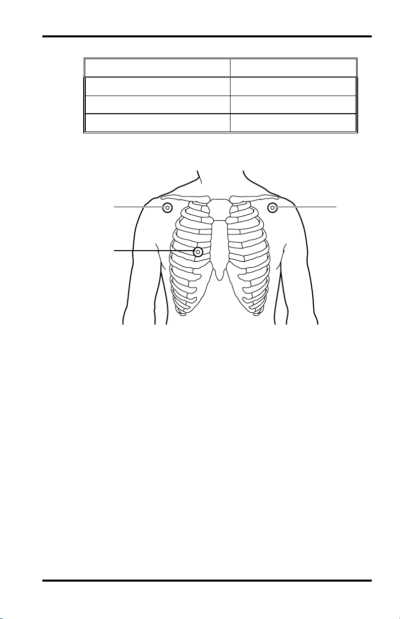
ECG Monitoring
Table 16: ECG Lead Pairs (for Standard Leads Placement)
Lead-Select Option Electrode Differential
IRA ➞ LA
II RA ➞ LL
III LA ➞ LL
3
2
1
Figure 14: Modified Chest Lead (MCL1) Placement
(if using MCL1, select Lead II)
1 RA 2 LL 3 LA
59
Page 66

ECG Monitoring
CONTROLLING ECG FUNCTIONS VIA NUMERIC FRAME
/min
0.5
SpO
mV
cm
II
2
SpO
85
%
2
97
17
mmHg
( )
NIBP Ð Blocked Hose
x
X
4
/min
Adult 2/14/95 16:34:36
3
85
Figure 15: Heart Rate Display
1. Units of Measure 3. HR Source Icon
2. HR Value 4. HR Icon
Table 17: Heart Rate Menu
Level 1 Menu Level 2 Menu or Response
Title: Heart Rate Menu
Heart Rate Tone Source SpO2, ECG
Heart rate limits Variable (refer to Table 13,
HR alarm silence icon On/Off
Return
140/90
(106)
180
/min
30
14
C
37.8
( )
T
1
2
page 50)
Exits Level 1 menu
immediately, returns to
Monitoring Screen
60
Page 67

ECG Monitoring
The calculated heart rate may be derived from different sources,
as shown by the icon in the frame: ECG, SpO
, or NIBP. The
2
NPB-4000/C automatically derives heart rate from ECG
whenever a valid ECG signal is present. If ECG is not present,
but SpO
the SpO
is being monitored, the heart rate value is derived from
2
signal. If neither ECG nor SpO2 is available, heart rate
2
derived from NIBP will be displayed. If HR is derived from
NIBP, that value will only be displayed for 3 minutes after the
NIBP measurement, then the value is removed from the display.
A short pulse tone will sound, synchronous with each heartbeat.
This heart rate tone may be derived from either of two sources:
SpO
or ECG, as indicated in Table 17, page 60. When SpO2 is
2
the source, the pitch varies proportionally with changes in
oxygen saturation, rising as SpO
increases toward 100%, and
2
falling as it decreases. If the source is ECG, the heart rate tone
does not change pitch. The volume of the heart rate tone may be
adjusted by pressing the front panel Heart Rate Tone Volume
switch, then turning the knob.
CONTROLLING ECG WAVEFORM VIA GRAPHIC FRAME
When ECG leads are connected to the patient, the top graphic
frame always displays the ECG waveform.
61
Page 68
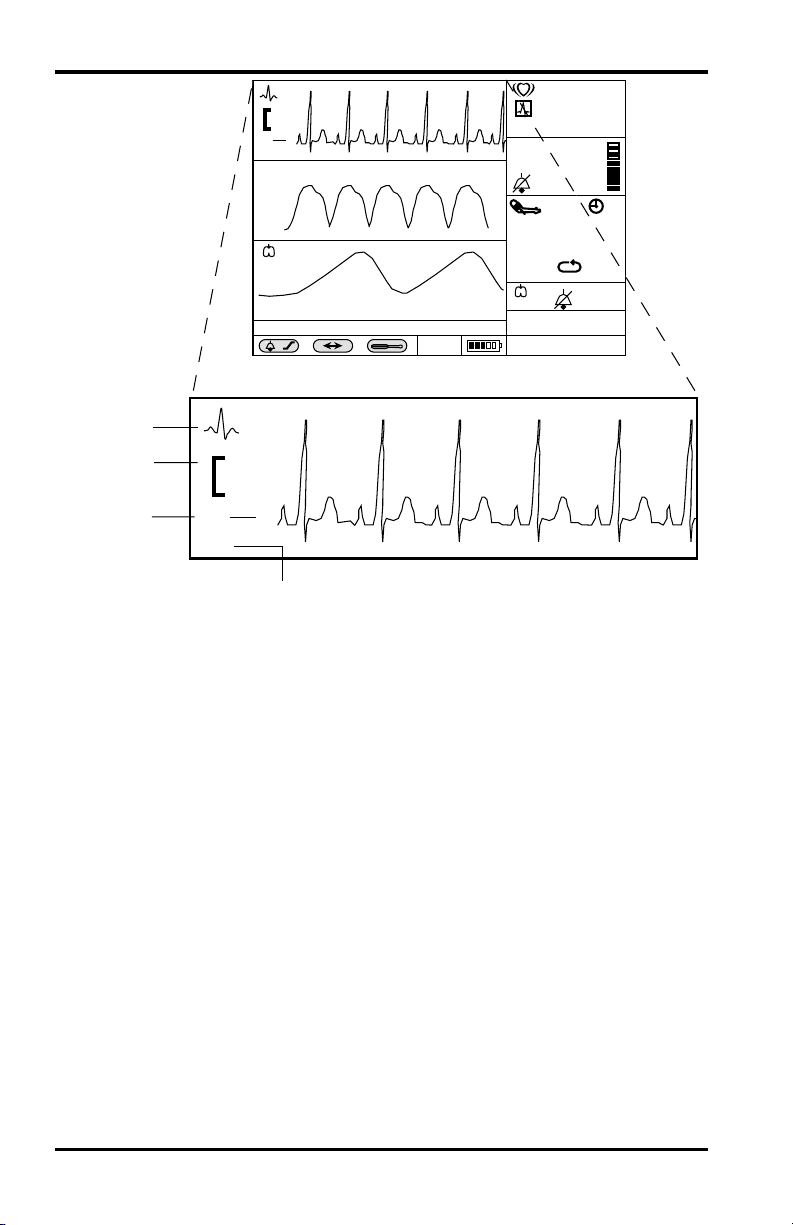
ECG Monitoring
/min
0.5
II
SpO2
mV
cm
SpO
85
%
2
97
mmHg
( )
T
140/90
(106)
/min
( )
NIBP Ð Blocked Hose
x
X
Adult 2/14/95 16:34:36
4
3
0.5
mV
cm
2
II
1
Figure 16: ECG Waveform
1. Lead Pair
2. Size Scale
3. Size Bar 1 cm
4. ECG Icon
17
180
30
14
C
37.8
62
The standard size bar, with a height of 1 cm, serves as a visual
reference for the ECG waveform.
Page 69

ECG Monitoring
Table 18: ECG Waveform Menu
Level 1 Menu Level 2 Menus or Response
Title: ECG WAVEFORM MENU
Lead Select I, II, III
Sweep Speed 12.5 mm/s, 25 mm/s, 50 mm/s
Size 0.5 mV/cm, 1 mV/cm, 2 mV/cm,
4 mV/cm
Pacer Detect On, Off
Extended Low Frequency Range On, Off
other graphic type choices:
>ECG Waveform
SpO
2 Waveform
Respiration Waveform
Tabular Trend
HR Graphic Trend
SpO
2 Graphical Trend
NIBP Graphical Trend
RR graphical Trend
Temperature Graphical Trend
Return
Extended Low Frequency Range
When Extended Low Frequency Range is On, the monitor
provides better ST segment resolution. However, the increased
bandwidth may result in low-frequency wander of the ECG
baseline, so it is generally recommended that this feature be kept
Off except when better ST segment resolution is specifically
required.
No Level 2 menu for these items;
selection of a new graphic type
immediately causes the title and
the first, menu items to update,
reflecting the new choice.
Note: For consistency, the other
display choices are present,
but in frame 1 they can not
be selected as long as ECG
leads are on patient.
Exits Level 1 menu, returns to
Monitoring Screen
63
Page 70

ECG Monitoring
Pacer Detect
Pacer detect should always be On for patients with pacemakers
(refer to safety warning at beginning of chapter). When Pacer
Detect is On, the NPB-4000/C detects and filters
pacemaker-generated signals so that they will not be measured in
determining a patient’s heart rate. Detected pacemaker signals
will be displayed on the ECG waveform (screen and printout) as
a positive-going spike. Monitoring of non-pacemaker patients is
generally not affected when Pacer Detect is enabled; however, in
some instances if the patient does not have a pacemaker, it may
be desirable to turn the detection function Off so that artifacts in
the waveform will not be mistaken for a pacemaker signal.
ECG Leads Off
The NPB-4000/C can determine when all three ECG leads are
properly attached to the patient. Should one or more of the leads
come off, or lose good electrical contact, after the monitor has
established that all 3 leads are attached, a low-priority “ECG
Leads Off” alarm will be issued, alerting the caregiver to remedy
the problem.
Occasionally, electromagnetic “noise” may cause the ECG
circuit to electrically “saturate”. If this condition occurs, the
NPB-4000/C will issue an ECG Leads Off alarm. Occurrence is
rare, and duration should be short. As soon as the condition
ceases, the “ECG Leads Off” alarm will automatically clear.
64
Page 71

NIBP MONITORING
General
NIBP Safety Information
Setup Connections
NIBP Measurement Modes
Controlling NIBP Functions via Numeric Frame
GENERAL
NIBP processing by the monitor uses the oscillometric
measuring technique. A motorized pump inflates the cuff to
initially blocking the flow of blood in the extremity. Then,
under monitor control, the pressure in the cuff is gradually
reduced, while a pressure transducer detects air pressure and
transmits a signal to the NIBP circuitry.
When the cuff pressure is still above systolic pressure, small
pulses or oscillations in the cuff pressure begin to be sensed by
the transducer. As the cuff continues to deflate, oscillation
amplitude increases to a maximum and then decreases. When
maximum oscillation amplitude occurs, the cuff pressure at that
time is measured as mean arterial pressure (MAP). The systolic
and diastolic pressures are calculated based on analysis of the
oscillation amplitude profile.
NIBP SAFETY INFORMATION
WARNINGS: Use only SCBP Series Blood Pressure Cuffs
and the SHBP-10 Hose or a hose and cuff recommended by
Nellcor’s Technical Services. Using other cuffs or hoses may
result in inaccuracies.
WARNING: Inaccurate measurements may be caused by
incorrect cuff application or use, such as placing the cuff too
loosely on the patient, using the incorrect cuff size, or not
placing the cuff at the same level as the heart, leaky cuff or
hose, and excessive patient motion.
65
Page 72

NIBP Monitoring
WARNING: The NPB-4000/C displays results of the last
blood pressure measurement until another measurement is
completed. If a patient’s condition changes during the time
interval between measurements, the NPB-4000/C will not
detect the change or indicate an alarm condition.
WARNING: As with all automatically inflatable blood
pressure devices, continual cuff measurements can cause
injury to the patient being monitored. Weigh the advantages
of frequent measurement and/or use of stat mode against the
risk of injury.
WARNING: In some cases, rapid, prolonged cycling of an
oscillometric, noninvasive blood pressure monitor cuff has
been associated with any or all of the following: ischemia,
purpura, or neuropathy. Apply the oscillometric cuff
appropriately, according to instructions, and check the cuff
site and cuffed extremity regularly when blood pressure is
measured at frequent intervals or over extended periods of
time.
66
WARNING: Check the patient’s limb on which the cuff is
applied to assure that circulation is not constricted.
Constriction of circulation is indicated by discoloration of
the extremity. This check should be performed at the
clinician’s discretion at regular intervals based on the
circumstances of the specific situation.
WARNING: Do not place the cuff on an extremity being
used for intravenous infusion or any area where circulation
is compromised or has the potential to be compromised.
WARNING: The blood pressure cuff should not be applied
to the same extremity as the one to which an SpO2 sensor is
attached, since cuff inflation will disrupt SpO2 monitoring
and lead to nuisance alarms.
Page 73

WARNING: During use on patients, ensure that heavy
objects are not placed on the hose. Avoid crimping or undue
bending, twisting, or entanglement of the hose.
Note: A patient’s vital signs may vary dramatically during
administration of agents affecting the cardiovascular
system, such as those used to raise or lower blood
pressure or raise or lower heart rate.
SETUP CONNECTIONS
Use only a Nellcor SHBP-10 hose and SCBP-Series cuff with
the NPB-4000/C or a hose and cuff recommended by Nellcor’s
Technical Services.
Measure the patient’s limb and select the proper size cuff. As a
general rule, cuff width should span approximately two-thirds of
the distance between the patient’s elbow and shoulder. Refer to
Table 19.
NIBP Monitoring
Table 19: Cuff Sizes
Model Number Limb Circumference Range
SCBR-6R; infant 6 cm (2.4 in.) 10 - 19 cm (4.0 - 7.5 in.)
SCBP-9R; child/adult
18 - 26 cm (7.1 - 10.2 in.)
9 cm (3.5 in.)
SCBP-12R; adult 12 cm (4.75
25 - 35 cm (9.9 - 13.8 in.)
in.)
SCBP-15R; large arm 15 cm
33 - 47 cm (13.0 - 18.5 in.)
(6.0 in.)
SCBP-18R; thigh 18 cm (7.1 in.) 46 - 66 cm (18.1 - 26.0 in.)
Follow cuff directions for use for applying the cuff to the arm or
thigh. Connect the hose to the front panel connector of the
monitor.
67
Page 74

NIBP Monitoring
NIBP MEASUREMENT MODES
Blood pressure measurements can be made in three modes:
Single
One measurement of each of the three blood pressures
(Systolic/Mean Arterial Pressure/Diastolic) is made and
displayed in the numeric frame.
Automatic
Measurements are made at preset intervals.
STAT
As many measurements as possible are made within a 5-minute
period.
Adjustable Initial Inflation Pressure
The user may select an initial cuff inflation pressure. This is
particularly important with children, since an initial cuff
inflation pressure of 180 mmHg may be uncomfortable, and is
typically higher than it needs to be. The initial inflation pressure
can be set from 100 to 280 mmHg, in intervals of 20 mmHg.
The numeric display in the lower right corner of the NIBP frame
indicates the setting of the initial inflation pressure which will
be used during the next measurement or the instantaneous
pressure in the cuff whenever a measurement is underway.
The initial inflation pressure is determined in one of two ways:
1) Upon power up, and immediately after making a change in the
adjustable initial inflation pressure via the NIBP menu, the
initial inflation pressure is determined by the setting indicated in
the NIBP menu. 2) Immediately after an NIBP reading has been
successfully completed, the initial inflation value is changed to
the just-completed Systolic pressure plus 50 mmHg (rounded off
to the nearest 5 mmHg).
To Initiate a Single Blood Pressure Measurement
Press (momentarily) the front panel NIBP Start/Stop switch. A
single blood pressure measurement will be made.
In addition to displaying the three pressure measurements, the
monitor numeric frame displays a clock icon and a numeric
value, which indicate the elapsed time in minutes since last
taking a measurement.
68
Page 75

The measurements remain in the numeric frame for 60 minutes.
At the end of the 60-minute interval, the measured value and the
icon are removed from the display.
As soon as an NIBP measurement begins, any existing NIBP
values in the numeric frame are removed, and the current,
variable value of the cuff pressure is shown. Systolic, diastolic,
and MAP values are presented when the measurement is
completed.
Absence of valid measurement values because of a low-priority
alarm condition will result in “dashes” in the display.
To Make NIBP Measurements Automatically
Select the desired automatic measurement interval from the
menu, accessed via the NIBP numeric frame. Upon selection,
automatic mode is activated and the initial measurement will be
made “X” minutes later (where “X” is the chosen interval). If a
measurement is desired immediately, press the front panel NIBP
Start/Stop switch.
The NIBP numeric frame will display the AUTO mode icon and
the number of minutes selected for the interval between
measurements. This icon and its numeric value are in addition
to the clock icon and elapsed time since last measurement.
NIBP Monitoring
To initiate STAT mode of NIBP operation
Press the front panel NIBP STAT switch and hold it for at least 2
seconds.
While STAT mode is active (5 minutes), the STAT icon appears
in the numeric frame; the clock icon and minutes displays are
removed.
Upon completion of STAT mode, the last measurement made in
that mode is displayed, and both the clock icon and elapsed time
numeric return to the display.
At 60 minutes after completion of the STAT measurements, the
displayed NIBP measurement and the clock icon are removed.
69
Page 76

NIBP Monitoring
To Stop Blood Pressure Measurements
If a measurement is in process, press the front panel NIBP
Start/Stop switch at any time that you wish to stop the current
measurement and deflate the cuff. If an automatic measurement
is underway, the interval time will be reset.
Low Priority NIBP Alarms
Several conditions may occur to disrupt an NIBP measurement.
Table 20 summarizes the conditions and the recommended
corrective action.
Table 20: Low Priority NIBP Alarms
Low Priority Alarm
Recommended Action
Message
NIBP - No Cuff Check to see that the cuff is present. Check the
cuff and hose connections for leaks. Take a
measurement again.
NIBP - Blocked Hose Check to see that the hose is not obstructed or
pinched. Take a measurement again.
NIBP - Artifact Monitor detected artifact, usually caused by
patient movement. In the presence of moderate
artifact, the monitor may be able to complete
the measurement and display blood pressure
values. However, in this case the clinician may
wish to repeat the measurement if the values
seem questionable. More severe artifact will
prevent the measurement from being
completed, and dashes will be displayed in the
NIBP numeric frame. In this case, check the
patient, cuff application and cuff orientation.
Take a measurement again.
NIBP - Time-Out Measurement could not be completed within
the normal amount of time. Check the patient.
Check the cuff application and orientation.
Take a measurement again.
70
Page 77

NIBP Monitoring
CONTROLLING NIBP FUNCTIONS VIA NUMERIC FRAME
/min
mV
0.5
II
SpO
cm
2
SpO
%
2
97
mmHg
( )
NIBP Ð Blocked Hose
x
7
X
mmHg
Adult 2/14/95 16:34:36
17
6
140/90
5
1. Timer Icon-Minutes Since Last Measurement
2. Systolic / Diastolic Values
3. Initial cuff inflation pressure (Note)
4. Auto Mode Icon-Interval In Minutes
5. Mean Arterial Pressure Value
6. NIBP Icon
7. Units of Measure
(106)
180
30
Figure 17: NIBP Screen
140/90
(106)
( )
/min
C
T
1
2
3
4
85
30
37.8
17
180
14
Note: If measurement is underway, this field displays the
instantaneous pressure in the cuff.
71
Page 78

NIBP Monitoring
Table 21: NIBP Menu
Level 1 Menu Level 2 Menus or Response
Title: NIBP MENU
Automatic Mode Interval Off, 1 min, 3 min, 5 min, 10 min,
15 min, 30 min, 60 min, 90 min
Initial Inflation Pressure 100, 123, 140, 160, 180, 200, 220, 240,
260, 280
S/D/M limits Variable (refer to Table 13, page 50)
Alarm silence icon On/Off
Return
Exits Level 1 menu immediately,
returns to Monitoring Screen
72
Page 79

SpO2 MONITORING
General
Safety Information
2
SpO
Setup Connections
Functions via Numeric Frame
Controlling SpO
Controlling SpO
Pulse Search Condition
GENERAL
Pulse oximetry works by applying a sensor to a pulsating
arteriolar vascular bed. The sensor contains a dual light source
and photodetector. Bone, tissue, pigmentation, and venous
vessels normally absorb a constant amount of light over time.
The arteriolar bed normally pulsates and absorbs variable
amounts of light during systole and diastole, as blood volume
increases and decreases. The ratio of light absorbed at systole
and diastole is translated into an oxygen saturation
measurement. This measurement is referred to as SpO
The NPB-4000/C utilizes C-LOCK® ECG synchronization to
enhance signal processing during patient movement or poor
perfusion. C-LOCK synchronization utilizes the QRS signal as a
reference point for identifying the oximetry pulse, thus
enhancing “good” pulses and reducing the effect of random
artifacts associated with motion and low perfusion.
2
Waveform via Graphic Frame
2
.
2
The measured SpO
value from an oximeter may differ from the
2
saturation value that is calculated from a blood gas partial
pressure of oxygen (PO
). This usually occurs because the
2
calculated saturation was not appropriately corrected for the
effects of variables that shift the relationship between PO
and
2
saturation: pH, temperature, partial pressure of carbon dioxide
(PCO
), 2,3-DPG, and fetal hemoglobin.
2
73
Page 80

SpO2 Monitoring
This monitor measures functional saturation — oxygenated
hemoglobin expressed as a percentage of the hemoglobin that
can transport oxygen. It does not detect significant amounts of
dysfunctional hemoglobin, such as carboxyhemoglobin or
methemoglobin. In contrast, hemoximeters such as the IL482
report fractional saturation — oxygenated hemoglobin expressed
as a percentage of all measured hemoglobin, including measured
dysfunctional hemoglobin. To compare functional saturation
measurements to those from an instrument that measures
fractional saturation, fractional measurements must be converted
as follows:
functional saturation =
100 – (% carboxyhemoglobin + % methemoglobin)
SpO2 SAFETY INFORMATION
fractional saturation
x 100
WARNINGS: Use only Nellcor SpO
2 sensors for SpO2
measurements. Other SpO2 sensors may cause improper
NPB-4000/C performance.
WARNING: Tissue damage can be caused by incorrect
application or use of an SpO2 sensor, for example by
wrapping the sensor too tightly or by applying supplemental
tape. Inspect the sensor site as directed in the sensor
directions for use to ensure skin integrity and correct
positioning and adhesion of the sensor.
WARNING: Do not use damaged SpO2 sensors. Do not use
an SpO2 sensor with exposed optical components. Do not
immerse sensor completely in water, solvents, or cleaning
solutions because the sensor and connectors are not
waterproof. Do not sterilize SpO2 sensors by irradiation,
steam, or ethylene oxide. Refer to the cleaning instructions
in the directions for use for reusable SpO2 sensors.
WARNING: Inaccurate readings could result if a sensor is
used incorrectly. Before using a sensor, carefully read and
understand the sensor directions for use.
74
Page 81

SpO2 Monitoring
WARNING: Inaccurate measurements may be caused by:
• incorrect sensor application or use
• significant levels of dysfunctional hemoglobin (such as
carboxyhemoglobin or methemoglobin)
• intravascular dyes such as indocyanine green or
methylene blue
• exposure to excessive illumination, such as surgical
lamps (especially ones with a xenon light source),
bilirubin lamps, fluorescent lights, infrared heating
lamps, or direct sunlight
• excessive patient movement
• high-frequency electrosurgical interference and
defibrillators
• venous pulsations
• placement of a sensor on an extremity with a blood
pressure cuff, arterial catheter, or intravascular line
• the patient has hypotension, severe vasoconstriction,
severe anemia, or hypothermia
• there is arterial occlusion proximal to the sensor
• the patient is in cardiac arrest or is in shock
WARNING: Loss of pulse signal can occur in any of the
following situations:
• the sensor is too tight
• there is excessive illumination from light sources such as
a surgical lamp, a bilirubin lamp, or sunlight
• a blood pressure cuff is inflated on the same extremity as
the one to which an SpO2 sensor is attached
SETUP CONNECTION
Use only Nellcor sensor extension cables and SpO
the NPB-4000/C.
When selecting a sensor, consider the patient’s weight and
activity, adequacy of perfusion, availability of sensor sites, need
for sterility, and anticipated duration of monitoring. For more
information, refer to Table 22, page 76, or your local Nellcor
representative.
sensors with
2
75
Page 82

SpO2 Monitoring
Table 22: SpO2 Sensors
Oxygen Transducer Model
Oxisensor II
(sterile, single use)
Oxicliq
(sterile, single, use)
Dura-y
(nonsterile, reusable)
Durasensor
N-25*
I-20
D-20
D-25 (L)
R-15
A
P
N*
I
D-YS*
D-YSE
DS-100A >40 kg
Patient
Weight
<3 or >40 kg
3 to 20 kg
10 to 50 kg
>30 kg
>50 kg
>30 kg
10 to 50 kg
<3 or >40 kg
3 to 20 kg
>1 kg
>30 kg
(nonsterile, reusable)
Nellcor reflectance sensor
RS-10 >40 kg
(Nonsterile, limited reuse)
*Although these Nellcor sensors are specified for use on very
small patients, as well as pediatric and adult patients, the NPB4000/C monitor should NOT be used to monitor neonates.
76
Observe all warnings and cautions in the directions for use
supplied with these sensors. Carefully apply the sensor to the
patient, as described in the sensor directions for use. The sensor
may be connected directly to the NPB-4000/C front panel
connector, identified with the SpO
icon. Typically, however, it
2
is more convenient to connect the sensor to the monitor by using
a Nellcor SpO
extension cable. Periodically check to see that
2
the sensor remains properly positioned on the patient and that
skin integrity is acceptable. Refer to sensor directions for use.
Page 83

SpO2 Monitoring
High ambient light sources such as surgical lights (especially
those with a xenon light source), bilirubin lamps, fluorescent
lights, infrared heating lamps, and direct sunlight can interfere
with the performance of an SpO
sensor. To prevent
2
interference from ambient light, ensure that the sensor is
properly applied, and cover the sensor site with opaque material.
Failure to take this action in high ambient light conditions may
result in inaccurate measurements.
If patient movement presents a problem, verify that the sensor is
properly and securely applied; move the sensor to a less active
site; use an adhesive sensor that tolerates some patient motion;
or use a new sensor with fresh adhesive backing.
For reusable sensors, follow the sensor directions for use for
cleaning and reuse. For-single-patient use sensors, use a new
sensor for each patient. Do not sterilize any Nellcor sensor by
irradiation, steam, or ethylene oxide.
77
Page 84
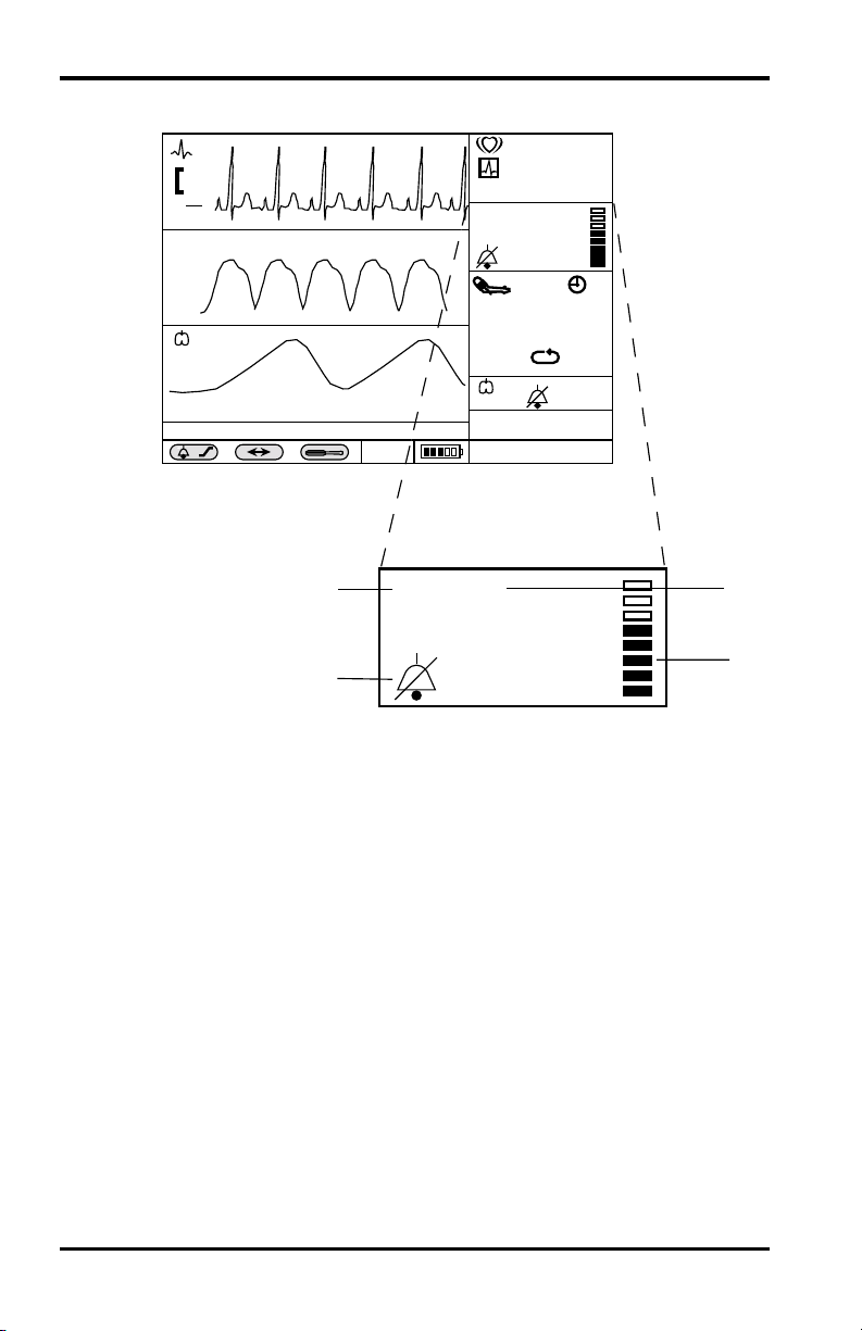
SpO2 Monitoring
CONTROLLING SpO2 FUNCTIONS VIA NUMERIC FRAME
/min
mV
0.5
cm
II
SpO2
( )
NIBP - Blocked Hose
x
X
Adult 2/14/95 16:34:36
4
3
Figure 18: SpO2 Screen
1. Units of Measure
2. Pulse Amplitude Indicator
3. Audible Alarm Bell Icon
Icon
4. SpO
2
SpO2
SpO2
mmHg
140/90
( )
/min
T
%
97
85
%
97
(106)
C
180
30
14
37.8
17
1
2
78
Page 85

SpO2 Monitoring
Table 23: SpO2 Menu
Level 1 Menu Level 2 Menus or Response
Title: SpO2 MENU
SpO2 Response Slow, Normal, Fast
C-Lock On, Off
SpO2 limits Variable (refer to Table 13, page 50)
SpO2 alarm silence icon On/Off (audible on)
Return
SpO2 Response Modes
Normal (Mode 1): Recommended for most clinical situations
in conjunction with C-LOCK ECG synchronization to reduce the
effect of patient motion.
Fast (Mode 2): Useful for special applications such as sleep
studies in which the user desires fast response. Most affected by
patient motion.
Slow (Mode 3): Least affected by patient motion. Should be
used only if Normal mode with C-LOCK does not perform
acceptably. User must be aware that changes in SpO
reported more slowly relative to other modes. Heart rate from
SpO
is not displayed when slow response mode is enabled.
2
C-LOCK Operation
When C-LOCK is turned on in the SpO2 menu, C-LOCK
automatically becomes operational any time a valid ECG signal
is detected by the monitor. It is not necessary to turn C-LOCK
off if an ECG signal is not available; the monitor handles this
function automatically.
Exits Level 1 menu immediately,
returns to Monitoring Screen
are
2
If the ECG signal is noisy, or of poor quality, SpO
may be improved by turning C-LOCK off.
performance
2
79
Page 86
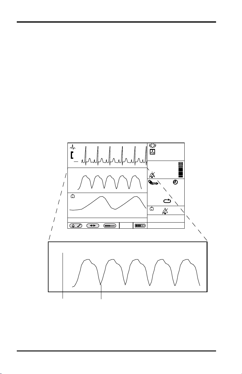
SpO2 Monitoring
Pulse Amplitude Indicator
The pulse amplitude indicator is a segmented display within the
SpO
numeric frame that shows the relative strength of the
2
detected pulse. With each pulse, contiguous segments are
briefly filled; the stronger the pulse, the greater the number of
filled segments.
Pulse Search Condition
The NPB-4000/C displays a status message “SpO2 Pulse
Search” to indicate that it is attempting to locate the patient’s
pulse. An SpO
order for the SpO
sensor must be connected to the NPB-4000/C in
2
2
pulse search condition to occur.
CONTROLLING SpO
mV
0.5
cm
II
SpO
2
( )
NIBP Ð Blocked Hose
SpO
2
2
WAVEFORM VIA GRAPHIC FRAME
2
/min
85
%
SpO2
97
30
14
37.8
17
180
mmHg
140/90
(106)
( )
/min
C
T
x
X
Adult 2/14/95 16:34:36
1
80
Figure 19: SpO2 Waveform Screen
1. SpO
2. SpO
Waveform
2
Icon
2
Page 87

SpO2 Monitoring
Table 24: SpO2 Waveform
Level 1 Menu Level 2 Menus or Response
Title: SpO2 WAVEFORM
Sweep speed 12.5 mm/s, 25 mm/s, 50 mm/s
ECG Waveform
>SpO
2 Waveform
Respiration Waveform
Tabular Trend
HR Graphical Trend
SpO
Graphical Trend
2
NIBP Graphical Trend
RR Graphical Trend
Temperature Graphical Trend
Return
.
No level 2 menu for these items;
selection of a new graphic type
immediately causes the title and
the first menu items to update,
reflecting the new choice.
Exits Level 1 menu immediately,
returns to Monitoring Screen
81
Page 88

[THIS PAGE INTENTIONALLY LEFT BLANK]
Page 89

RESPIRATION MONITORING
General
Respiration Safety Information
Setup Connections
Controlling Respiration Functions via Numeric Frame
Controlling Respiration Waveform via Graphic Frame
GENERAL
The patient’s respiration is detected by using two of the three
leads of the ECG electrodes and cable. A low-level excitation
signal is applied to these leads, and the variation of the thoracic
impedance caused by the breathing effort is sensed and
processed for measurement and screen presentation.
Real-time respiratory information is presented as a waveform in
a graphic frame; respiration rate is presented in a numeric frame
and in tabular trend data.
RESPIRATION SAFETY INFORMATION
WARNINGS: The NPB-4000/C is a respiration rate monitor
only. The NPB-4000/C should NOT be used for the detection
of apnea. Do not use the NPB-4000/C to monitor neonates.
WARNING: Keep patients under close surveillance when
monitoring respiration. Respiration signals are relatively
more sensitive to interference from radiated electromagnetic
signals. Thus, it is possible, although unlikely, that radiated
electromagnetic signals from sources external to the patient
and NPB-4000/C can cause inaccurate respiration readings.
Do not rely entirely on the NPB-4000/C respiration readings
for patient assessment.
83
Page 90

Respiration Monitoring
SETUP CONNECTIONS
The respiration signal is acquired using the ECG electrodes,
leads and cable. Refer to the ECG Monitoring section, page
55, for information regarding patient connection.
Respiration monitoring performance may be improved by an
alternate electrode placement, relative to standard ECG
electrode placement.
• Left arm (LA) electrode placement is the left
midaxillary line just below the nipple level.
• Right arm (RA) electrode placement is the right
midaxillary line just below the nipple level.
• Left leg (LL) electrode placement is unchanged
relative to standard ECG lead placement.
The user should be aware that this alternate electrode placement
may change the shape and amplitude of the ECG waveform.
CONTROLLING RESPIRATION FUNCTIONS VIA NUMERIC FRAME
/min
84
0.5
SpO2
mV
cm
II
SpO2
85
%
97
( )
4
NIBP Ð Blocked Hose
x
X
/min
( )
mmHg
140/90
( )
/min
T
Adult 2/14/95 16:34:36
(106)
C
1
180
30
14
37.8
17
14
3
Figure 20: Respiration Rate Screen
1. Units of Measure 3. Audible Alarm Bell Icon
2. Measured Value 4. Respiration Icon
2
Page 91

Respiration Monitoring
Table 25: Respiration Rate Menu
Level 1 Menu Level 2 Menus or Response
Title: RESPIRATION RATE MENU
Respiration On, Off
Respiration rate limits Variable (refer to Table 13, page 50)
Respiration rate alarm On/Off (audible on)
Return
Exits Level 1 menu immediately,
returns to Monitoring Screen
Loss of Respiration Signal Alarm
If the NPB-4000/C patient monitor does not detect a respiration
signal for 40 consecutive seconds, a loss of respiration signal
alarm will be issued. Check the condition of the patient, then
check the condition of the electrodes and lead/cable connections.
The alternate electrode placement described in Setup
Connections, page 84, may improve respiration-monitoring
performance. If poor signal quality persists, the user may
choose to turn Off respiration monitoring, as described below.
CAUTION: When the respiration rate limits audible alarm
has been permanently silenced (the slashed-bell icon is
present), the loss of respiration signal audible alarm will also
be permanently silenced.
Respiration Monitoring On/Off
When respiration monitoring is turned Off in the Respiration
Rate menu, the respiration rate value and respiration waveform
will be blanked, and no respiration monitoring alarms will
function.
85
Page 92

Respiration Monitoring
CONTROLLING RESPIRATION WAVEFORM VIA GRAPHIC
FRAME
/min
mV
0.5
cm
SpO
2
( )
NIBP Ð Blocked Hose
2
( )
1
Figure 21: Respiration Waveform Screen
1. Respiration Waveform
2. Respiration Icon
85
%
SpO
2
97
30
14
37.8
17
180
mmHg
140/90
(106)
( )
/min
C
T
x
X
Adult 2/14/95 16:34:36
86
Page 93

Respiration Monitoring
Table 26: Respiration Waveform Menu
Level 1 Menu Level 2 Menus or Response
Title: RESPIRATION WAVEFORM MENU
Sweep Speed 6.25 mm/s, 12.5 mm/s, 25 mm/s
other graphic choices:
ECG Waveform
Waveform
2
SpO
>Respiration Waveform
Tabular Trend
HR Graphical Trend
SpO
Graphical Trend
2
NIPB Graphical Trend
RR Graphical Trend
Temperature Graphical Trend
Return
No level 2 menu for these items;
selection of a new graphic type
immediately causes the title and
first menu items to update,
reflecting the new choice.
Exits Level 1 menu immediately,
returns to Monitoring Screen
87
Page 94

[THIS PAGE INTENTIONALLY LEFT BLANK]
Page 95

TEMPERATURE MONITORING
General
Setup Connections
Controlling Temperature Functions via Numeric Frame
GENERAL
Measurement of patient temperature is accomplished by
processing the signal from a probe containing a resistance
element whose impedance is temperature dependent. These
devices are called thermistors. The signal from the probe is
conditioned by the monitor input circuitry, processed, and the
measured values are shown in the numeric frame.
Setup Connections
The NPB-4000/C patient monitor is designed to accept signals
from YSI Series 400-compatible thermistor probes.
Interchangeable probes in this series may be used for
esophageal, rectal, skin or surface, or airway temperature
measurement. Follow the directions for use accompanying the
temperature probe. If YSI-compatible probes are not readily
available, contact Nellcor’s Technical Services Department or
your local Nellcor representative. To avoid nuisance limit
alarms, the probe should be affixed to the patient before
connecting to the NPB-4000 and NPB-4000C front panel
connector.
89
Page 96
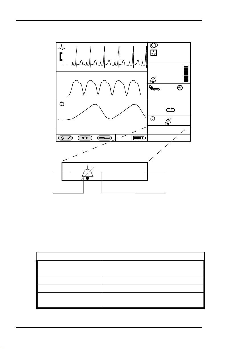
Temperature Monitoring
CONTROLLING TEMPERATURE FUNCTIONS VIA NUMERIC
FRAME
/min
mV
0.5
cm
II
SpO
2
( )
NIBP Ð Blocked Hose
x
4
T
3
Figure 22: Temperature Screen
1. Measured Value
2. Units of Measure
3. Alarm Bell
4. Temperature Icon
85
%
SpO2
97
1
180
30
14
37.8
17
mmHg
140/90
(106)
( )
/min
C
T
X
o
Adult 2/14/95 16:34:36
C
37.8
2
90
Table 27: Temperature Menu
Level 1 Menu Level 2 Menus or Response
Title: TEMPERATURE MENU
Units º C, º F
Temperature limits Variable (refer to Table 13, page 50)
Temperature alarm On/Off
Return
Exits Level 1 menu immediately,
returns to Monitoring Screen
Page 97

TRENDS
General
Displaying Trend Data
Selecting a 2-Hour Portion of the Graphical Trend for Display
Printing Trend Information (Printer Option Installed)
Changing the Vertical Scale Range
Selecting Different Trend Records
Graphical Trend Operation Summary
Tabular Trend Data
Transferring Trend via RS-232
GENERAL
Trend Data Storage
Trend Data in graphical or tabular format may be displayed on
the screen, and printed if a printer is installed.
Trend data for all parameters except NIBP is the average of a
20-second sample of the data. For NIBP, the trend data is the
measured values. Twelve (12) hours of trend data is stored in a
nonvolatile memory, and remain in storage when the monitor is
in Standby.
A new record of trend data is started each time the monitor is
turned On. A trend data record is defined as the data from one
power On event to the Standby power event. A date/time
annotation is included at the start of each new record (up to ten
are possible) so the record can be correlated with the patient.
Once trend memory has stored 12 hours of data, the oldest trend
data will be overwritten by new data.
Trend Displays
Trend data is displayed in graphical or tabular format. Trend
information in graphical format for a selected parameter is
shown as a line connecting each of the points representing the
stored 20-second average.
91
Page 98

Trends
NIBP values are shown as vertical lines. The vertical
displacement of the top of the line represents the systolic
pressure, the bottom represents the diastolic pressure, and a
short blank space in the line represents the mean arterial
pressure values. Two hours of graphic trend data are displayed
in one graphic frame.
There is one tabular trend format, containing trend data for all
monitored parameters. The tabular trend data values are
selected each time an NIBP measurement is made or once every
15 minutes, whichever comes first. In the event of an alarm
condition, each 20-second average is shown until the alarm is
corrected. In addition, during the alarm state, the limit(s) being
exceeded are displayed in reverse video. The selected trend
segment is obtained by user interaction with the menu.
DISPLAYING TREND DATA
1. Rotate the knob to highlight the graphic frame in which the
desired trend is to appear.
2. Press the knob.
3. The Level 1 menu for this frame appears in graphics frames
2 and 3.
4. Rotate the knob to highlight the trend description item in the
Level 1 menu.
5. Press the knob. Control is returned to the Level 1 menu.
6. Rotate the knob until the Return message is highlighted.
7. Press the knob.
The display now contains a graphical trend (if selected) or a
tabular trend (if selected) in the previously highlighted graphic
frame location.
Trend Screen Example
In Figure 23, page 93, tabular trend data for all monitored
parameters is displayed in the middle graphics frame; graphical
trend data for the SpO
graphics frame.
The newest data appears at the right of graphical trends, and at
the top of tabular trends.
92
parameter is displayed in the bottom
2
Page 99
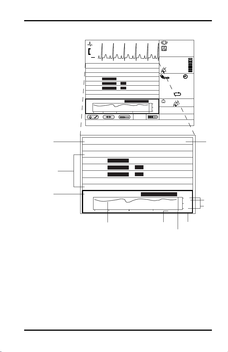
Trends
Additional control of trend operations is obtained by interaction
with the trend display.
/min
10
mV
0.5
cm
II
TREND - 2/14 8/8
Time NIBP HR SpO2 RR T
16:34:36 140/90(97) 85 97 14 37.8
210/145(169)
16:24:36 84 98 10 38.0
210/150/165
16:14:36 96 14 38.1
210/150/165
16:14:36 96 14 38.1
16:05:36 155/97(108) 95 95 18 38.9
16:05:36 156/100(112) 100 94 18 39.3
SpO2 - 2 HOURS 8/8
x
X
110
110
Press Knob to Exit Scroll
100
%
80
60
16:34 2/14
Adult 2/14/95 16:34:36
TREND - 2/14 8/8
Time NIBP HR SpO2 RR T
16:34:36 140/90(97) 85 97 14 37.8
16:24:36 84 98 10 38.0
9
8
16:14:36 96 14 38.1
16:14:36 96 14 38.1
16:05:36 155/97(108) 95 95 18 38.9
16:05:36 156/100(112) 100 94 18 39.3
SpO2 - 2 HOURS 8/8
210/145(169)
210/150/165
210/150/165
110
110
Press Knob to Exit Scroll
SpO2
T
85
%
97
mmHg
140/90
(106)
/min
C
16:34
180
30
14
37.8
100
80
60
2/14
17
1
%
2
3
7
6
4
5
Figure 23: Graphical and Tabular Trend Screens
1. Record Number/Total Records 6. Time
2. Units of Measure 7. Two Hours of Trend Data
3. Vertical Axis Range Scale 8. Title
4. Date 9. Five Tabular Rows
5. Time Bar 10. Title
93
Page 100

Trends
Figure 23 shows the eighth trend record out of eight stored, as
indicated by the 8/8 in the upper right corner of the trend screen
(1/8 would be the current one). The time bar at the right edge of
the trend graph indicates the most recent trend value in the
display and corresponds to the time value displayed below it.
Two hours of graphical trend and five rows of tabular data are
presented in their frames on the screen at any one time. The
capability for viewing more trend data is obtained by using the
scroll function.
SELECTING A 2-HOUR PORTION OF THE GRAPHICAL
TREND FOR DISPLAY:
1. Rotate the knob until the trend graphics frame is highlighted.
The highlighting is shown in Figure 23, page 93.
2. Press the knob.
The Level 1 menu for the waveform trend appears in graphic
frames 2 and 3. (The menu may temporarily obscure the
trend graphics frame.)
The first item is Scroll/Print Trend.
The display is shown in Figure 24, page 96.
94
3. Rotate the knob to highlight the top menu item Scroll/Print
Trend.
4. Press the knob. The Level 1 menu is removed from the
screen. The knob is now activated.
5. Rotate the knob to scroll through the record.
Counterclockwise rotation moves the 2-hour window
forward in time; clockwise rotation backs up the window.
Each rotational “click” of the knob moves the window in
15-minute increments.
6. After viewing the trend, press the knob again to exit the
scrolling function and return to the Level 1 menu. If no
other changes are desired, select Return to Return to the
normal monitoring screen.
 Loading...