

Page 1

SERVICE MANUAL
NPB-190 Pulse Oximeter
Caution: Federal law (U.S.) restricts this device to sale by or on the order of a physician.
To contact Mallinckrodt’s representative: In the United States, call 1.800.635.5267 or 314.654.2000; outside of the United
States, call your local Mallinckrodt representative.
1999 Mallinckrodt Inc. All rights reserved. 033925E-0599
0123
Page 2

Mallinckrodt, Inc.
675 McDonnell Boulevard
P.O. Box 5840
St. Louis, MO 63134
Tel 314.654.2000
Toll Free 1.800.635.5267
Nellcor Puritan Bennett
4280 Hacienda Drive
Pleasanton, CA 94588 USA
Mallinckrodt
Europe BV
Hambakenwetering 1
5231 DD’s-Hertogenbosch
The Netherlands
Tel +31.73.6485200
Nellcor Puritan Bennett is a wholly owned subsidiary of Mallinckrodt Inc. Nellcor and Nellcor Puritan Bennett are trademarks of
Mallinckrodt Inc.
To obtain information about a warranty, if any, for this product, contact Mallinckrodt Technical Services or your local Mallinckrodt
representative.
Purchase of this instrument confers no express or implied license under any Mallinckrodt patent to use the instrument with any sensor
that is not manufactured or licensed by Mallinckrodt.
Durasensor, and Oxisensor II, are trademarks of Mallinckrodt Inc.
Covered by one or more of the following U.S. Patents and foreign equivalents: 4,621,643; 4,653,498; 4,700,708; 4,770,179; 4,869,254;
Re.35.122; 4,928,692; 4,934,372; 5,078,136; and 5,368.224.
Page 3

TABLE OF CONTENTS
List of Figures
List of Tables
Table Of Contents ....................................................................................... iii
List Of Figures......................................................................................... v
List Of Tables .......................................................................................... vi
Section 1: Introduction............................................................................... 1-1
1.1 Manual Overview.......................................................................... 1-1
1.2 NPB-190 Pulse Oximeter Description.......................................... 1-1
1.3 Power-On Self Test...................................................................... 1-2
1.4 Related Documents...................................................................... 1-3
Section 2: Routine Maintenance................................................................ 2-1
2.1 Cleaning ....................................................................................... 2-1
2.2 Periodic Safety and Functional Checks ....................................... 2-1
2.3 Battery.......................................................................................... 2-1
Section 3: Performance Verification ......................................................... 3-1
3.1 Introduction .................................................................................. 3-1
3.2 Equipment Needed ...................................................................... 3-1
3.3 Performance Tests....................................................................... 3-1
3.4 Safety Tests ................................................................................. 3-9
Section 4: Audible Alarm Settings & Service Menu................................. 4-1
4.1 Introduction .................................................................................. 4-1
4.2 Audible Alarm Settings ................................................................. 4-1
4.3 Service Menu ............................................................................... 4-2
Section 5: Troubleshooting ....................................................................... 5-1
5.1 Introduction .................................................................................. 5-1
5.2 How To Use This Section............................................................. 5-1
5.3 Who Should Perform Repairs ...................................................... 5-1
5.4 Replacement Level Supported ..................................................... 5-1
5.5 Obtaining Replacement Parts ...................................................... 5-1
5.6 Troubleshooting Guide ................................................................. 5-2
5.7 Error Codes.................................................................................. 5-7
Section 6: Disassembly Guide................................................................... 6-1
6.1 Introduction .................................................................................. 6-1
6.2 Prior to Disassembly .................................................................... 6-1
6.3 Fuse Replacement ....................................................................... 6-2
6.4 Monitor Disassembly .................................................................... 6-3
6.5 Monitor Reassembly .................................................................... 6-4
6.6 Battery Replacement.................................................................... 6-5
6.7 Power Entry Module (PEM) Removal/Installation ........................ 6-6
6.8 Power Supply Removal/Installation.............................................. 6-7
6.9 Display PCB Removal/Installation................................................ 6-9
6.10 UIF PCB Removal/Installation...................................................... 6-10
6.11 Alarm Speaker Removal/Installation............................................ 6-11
Section 7: Spare Parts ................................................................................ 7-1
7.1 Introduction .................................................................................. 7-1
Section 8: Packing For Shipment .............................................................. 8-1
8.1 General Instructions ..................................................................... 8-1
iii
Page 4

Table of Contents
8.2 Repacking in Original Carton ....................................................... 8-1
8.3 Repacking in a Different Carton................................................... 8-3
Section 9: Specifications............................................................................ 9-1
9.1 General ........................................................................................ 9-1
9.2 Electrical....................................................................................... 9-1
9.3 Physical Characteristics ............................................................... 9-2
9.4 Environmental .............................................................................. 9-2
9.5 Alarms .......................................................................................... 9-2
9.6 Factory Default Settings ............................................................... 9-2
9.7 Performance ................................................................................ 9-3
Appendix (Serial Port Interface Protocol)................................................. A-1
A1 Introduction .................................................................................. A-1
A2 Enabling the Serial Port................................................................ A-1
A3 Connecting to the Serial Port ....................................................... A-1
A4 Real-Time Printout ....................................................................... A-2
A5 Nurse Call .................................................................................... A-5
Technical Supplement................................................................................ S-1
S1 Introduction .................................................................................. S-1
S2 Oximetry Overview....................................................................... S-1
S3 Circuit Analysis............................................................................. S-3
S4 Functional Overview..................................................................... S-3
S5 AC Input ....................................................................................... S-3
S6 Power Supply PCB Theory of Operation...................................... S-4
S7 Battery.......................................................................................... S-5
S8 User Interface PCB (UIF) ............................................................. S-5
S9 Front Panel Display PCB and Controls ........................................ S-8
S10 Schematic Diagrams .................................................................... S-9
iv
Page 5

LIST OF FIGURES
Table of Contents
Figure 1-1: NPB-190 Front Panel.................................................................. 1-2
Figure 1-2: NPB-190 Rear Panel .................................................................. 1-2
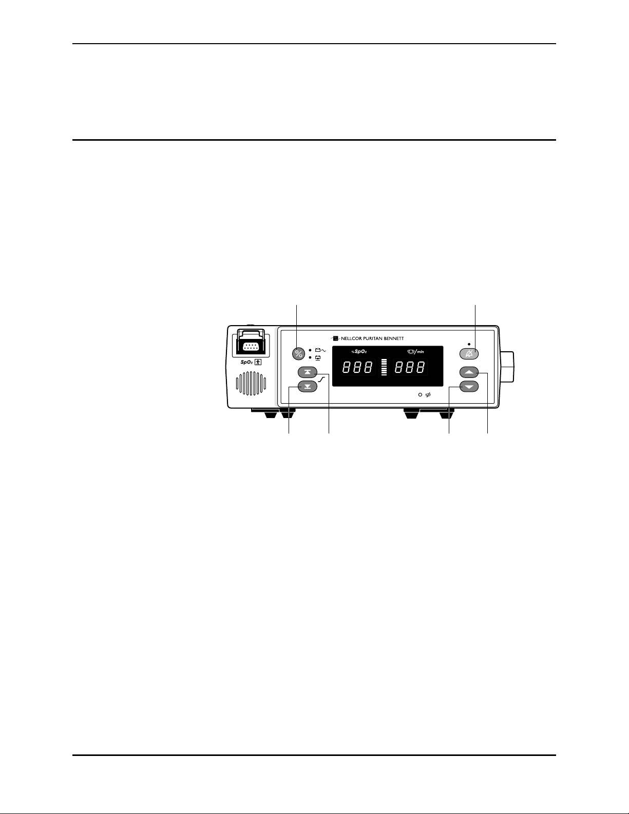
Figure 3-1: NPB-190 Controls....................................................................... 3-2
Figure 3-2: Self-Test Display......................................................................... 3-3
Figure 3-3: Adjusting High %SpO2 Alarm Limit ............................................ 3-3
Figure 3-4: Adjusting Low %SpO2 Alarm Limit ............................................. 3-4
Figure 3-5: Adjusting High Heart Rate Alarm Limit ....................................... 3-4
Figure 3-6: Adjusting Low Heart Rate Alarm Limit ........................................ 3-4
Figure 3-7: Alarm Silence Duration ............................................................... 3-6
Figure 3-8: Alarm Volume Display ................................................................ 3-7
Figure 4-1: NPB-190 Controls....................................................................... 4-1
Figure 6-1: Fuse Removal............................................................................. 6-2
Figure 6-2: NPB-190 Corner Screws ............................................................ 6-3
Figure 6-3: Separating Case Halves ............................................................. 6-4
Figure 6-4: Battery Removal ......................................................................... 6-5
Figure 6-5: Power Entry Module.................................................................... 6-6
Figure 6-6: Power Supply Leads Connections .............................................. 6-7
Figure 6-7: Power Supply.............................................................................. 6-8
Figure 6-8: Display PCB................................................................................ 6-9
Figure 6-9: UIF PCB...................................................................................... 6-10
Figure 6-10: Alarm Speaker .......................................................................... 6-12
Figure 7-1: NPB-190 Exploded View............................................................. 7-2
Figure 8-1: Repacking the NPB-190 ............................................................. 8-2
Figure A-1: Serial Port Pin Layout................................................................. A-2
Figure A-2: Real-Time Printout ..................................................................... A-2
Figure S-1: Oxyhemoglobin Dissociation Curve ........................................... S-2
Figure S-2: NPB-190 Functional Block Diagram ........................................... S-3
Figure S-3 Front End Red/IR Schematic Diagram ....................................... S-11
Figure S-4 Front End LED Drive Schematic Diagram.................................. S-13
Figure S-5 Front End Output Schematic Diagram ....................................... S-15
Figure S-6 Front End Power Supply Schematic Diagram ............................ S-17
Figure S-7 Isolation Barrier EIA-232 Port Schematic Diagram .................... S-19
Figure S-8 CPU Core Schematic Diagram .................................................. S-21
Figure S-9 PIC and Speaker Schematic Diagram ....................................... S-23
Figure S-10 Indicator Drive Schematic Diagram.......................................... S-25
Figure S-11 Core Power Supply Schematic Diagram .................................. S-27
Figure S-12 Parts Locator Diagram for UIF PCB ......................................... S-29
Figure S-13 Display PCB Schematic Diagram............................................. S-31
Figure S-14 Parts Locator Diagram for Display PCB ................................... S-33
Figure S-15 Power Supply Schematic Diagram ........................................... S-35
Figure S-16 Parts Locator Diagram for Power Supply PCB......................... S-37
v
Page 6

Table of Contents
LIST OF TABLES
Table 3-1: Dynamic Operating Range.......................................................... 3-8
Table 3-2: Earth Leakage Current Limits ..................................................... 3-10
Table 3-3: Enclosure Leakage Current Limits.............................................. 3-11
Table 3-4: Patient Leakage Current Limits .................................................. 3-12
Table 3-5: Patient Leakage Current Test Configurations - Mains
Voltage on the Applied Part ........................................................ 3-12
Table 4-1: Factory Default Settings.............................................................. 4-3
Table 5-1: Problem Categories .................................................................... 5-2
Table 5-2: Power Problems.......................................................................... 5-3
Table 5-3: Button Problems ......................................................................... 5-4
Table 5-4: Display/Alarms Problems............................................................ 5-4
Table 5-5: Operational Performance Problems ........................................... 5-5
Table 5-6: Serial Port Problems ................................................................... 5-6
Table 5-7: Error Codes................................................................................. 5-7
Table A-1: Serial Port Pin Outs .................................................................... A-1
Table A-2: Status Codes .............................................................................. A-4
vi
Page 7

SECTION 1: INTRODUCTION
1.1 Manual Overview
1.2 NPB-190 Pulse Oximeter Description
1.3 Power-On Self Test
1.4 Related Documents
1.1 MANUAL OVERVIEW
This manual contains information for servicing the Nellcor model NPB-190
Pulse Oximeter. Only qualified service personnel should service this product.
Before servicing the NPB-190, read the operator’s manual carefully for a
thorough understanding of operation.
Warning: Explosion hazard. Do not use the NPB-190 pulse oximeter in the
presence of flammable anesthetics.
1.2 NPB-190 PULSE OXIMETER DESCRIPTION
The Nellcor NPB-190 portable pulse oximeter is intended for continuous,
noninvasive measurement of functional oxygen saturation of arterial hemoglobin
(SpO
2), and pulse rate (measured by SpO2 sensor).
The monitor is intended for use on adult, pediatric, and neonatal patients in all
hospital-type facilities and in the home environment. It may be used during intrahospital transport when powered by its internal battery.
Digital displays are provided for oxygen saturation and pulse rate, and a 10segment LED bar indicates pulse amplitude. High and low alarm limits for
saturation and pulse rate can be adjusted by the operator. The NPB-190 can
operate on AC or a rechargeable internal battery power. The controls and
indicators for the NPB-190 are illustrated in Figures 1-1 and 1-2.
1-1
Page 8
Section 1: Introduction
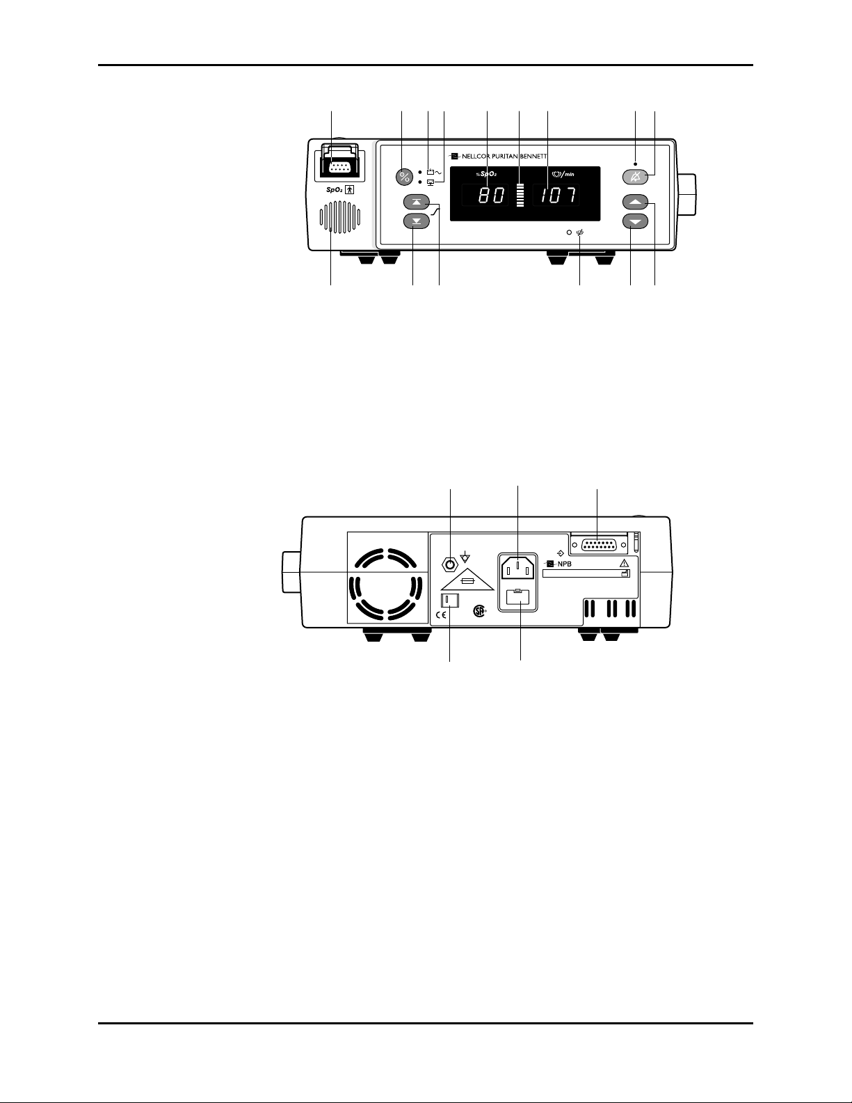
1 2 3 4 5 6 7 8 9
NPB190
101112131415
Figure 1-1: NPB-190 Front Panel
1. SpO2 Sensor Port 9. Alarm Silence Button
2. Power On/Standby Button 10. Adjust Up Button
3. AC/Battery Charging Indicator 11. Adjust Down Button
4. Low Battery Indicator 12. Pulse Search Indicator
5. %SpO2 Display 13. Upper Alarm Limit Button
6. Pulse Amplitude Indicator 14. Lower Alarm Limit Button
7. Pulse Beats per Minute Display 15. Speaker
8. Alarm Silence Indicator
1. Equipotential Terminal 4. Fuse Drawer
2. AC Connector 5. Voltage Selector Switch
3. Serial Port
1.3 POWER-ON SELF TEST
When the NPB-190 is turned on it will perform a POST (Power On Self Test).
During POST the following sequence should occur:
0123
1
2X
T 0.50A 250V
IPX1
5
CISPR 11
Group 1
Class B
NRTL/C
R
100-120 V~ 200-240 V~
50/60Hz
2
20 VA
4
SN
NELLCOR PURITAN BENNETT, INC.
PLEASANTON, CA 94588, U.S.A.
NELLCOR PURITAN BENNETT EUROPE BV,
's-HERTOGENBOSCH, THE NETHERLANDS
U.S. PATENTS:
4,621,643; 4,653,498;
4,700,708; 4,770,179;
4,869,254; Re. 35,122;
4,928,692; 4,934,372;
5,078,136
TM
3
NPB-190
MADE IN IRELAND
Figure 1-2: NPB-190 Rear Panel
036400-1098
1-2
• All indicator lights illuminate
• All segments of the numeric digits light
• All segments of the Pulse Amplitude Display light
Page 9

Section 1: Introduction
Upon completion of the POST display test, the software versions will be
displayed for approximately 2 seconds. Two versions are displayed:
• The first version is indicated by the numeral “1” in the leftmost segment of
the %SpO
2 display. The series of digits and decimal points displayed to the
right of the “1” represent the main processor software version.
• The second version is indicated by the numeral “2” in the leftmost segment
of the %SpO
2 display. The number(s) appearing to the right of the “2”
represent the subprocessor software version.
The software version numbers are often needed when calling Mallinckrodt’s
Technical Services Department or your local Mallinckrodt representative for
technical assistance. Record the numbers and have them available prior to
requesting technical assistance.
Upon successful completion of POST, the NPB-190 sounds a 1-second tone
indicating that the monitor has passed the test.
If the start-up sequence is not completed as described above do not use the
monitor.
1.4 RELATED DOCUMENTS
To perform test and troubleshooting procedures and to understand the principles
of operation and circuit analysis sections of this manual, you must know how to
operate the monitor. Refer to the NPB-190 operator’s manual. To understand the
various Nellcor sensors that work with the monitor, refer to the individual sensor
directions for use.
1-3
Page 10

Page 11

SECTION 2: ROUTINE MAINTENANCE
2.1 Cleaning
2.2 Periodic Safety and Functional Checks
2.3 Battery
2.1 CLEANING
Caution: Do not immerse the NPB-190 or its accessories in liquid or clean
with caustic or abrasive cleaners. Do not spray or pour any liquid on the
monitor or its accessories.
To clean the NPB-190, dampen a cloth with a commercial, nonabrasive cleaner
and wipe the exterior surfaces lightly. Do not allow any liquids to come in
contact with the power connector, fuse holder, or switches. Do not allow any
liquids to penetrate connectors or openings in the instrument cover. Wipe sensor
cables with a damp cloth. For sensors, follow the individual directions for use.
2.2 PERIODIC SAFETY AND FUNCTIONAL CHECKS
The following checks should be performed at least every 2 years by a qualified
service technician:
2.3 BATTERY
1. Inspect the exterior of the NPB-190 for damage.
2. Inspect safety labels for legibility. If the labels are not legible, contact
Mallinckrodt’s Technical Services Department or your local Mallinckrodt
representative.
3. Verify that the unit performs properly as described in paragraph 3.3.
4. Perform the electrical safety tests detailed in paragraph 3.4. If the unit fails
these electrical safety tests, do not attempt to repair.
5. Inspect the fuses in the Power Entry Module for proper value and rating.
The fuses are slow blow, 0.5 amp, and 250 volt.
Mallinckrodt recommends replacing the instrument battery every 2 years. When
the NPB-190 is going to be stored for 3 months or more remove the battery. To
replace or remove the battery, refer to Section 6, Disassembly Guide.
If the NPB-190 has been stored for more than 30 days, charge the battery as
described in paragraph 3.3.1. A fully discharged battery requires 14 hours to
receive a full charge. The battery is being charged anytime the instrument is
plugged into AC.
2-1
Page 12

Page 13

SECTION 3: PERFORMANCE VERIFICATION
3.1 Introduction
3.2 Equipment Needed
3.3 Performance Tests
3.4 Safety Tests
3.1 INTRODUCTION
This section discusses the tests used to verify performance following repairs or
during routine maintenance. All tests can be performed without removing the
NPB-190 cover. All tests except the battery charge and battery performance tests
must be performed as the last operation before the monitor is returned to the
user.
If the NPB-190 fails to perform as specified in any test, repairs must be made to
correct the problem before the monitor is returned to the user.
3.2 EQUIPMENT NEEDED
Equipment Description
Digital multimeter (DMM) Fluke Model 87 or equivalent
Durasensor oxygen transducer
Oxisensor II oxygen transducer
Pulse oximeter tester SRC-2
Safety analyzer Must meet current AAMI specifications
Sensor extension cable EC-4 or EC-8
Serial interface cable EIA-232 cable (optional)
Stopwatch Manual or electronic
DS-100A
D-25
3.3 PERFORMANCE TESTS
The battery charge procedure should be performed before monitor repairs
whenever possible. It should also be performed before and after performing the
battery performance test (paragraph 3.3.2).
Note: This section is written using Mallinckrodt factory-set defaults. If your
institution has preconfigured custom defaults, those values will be
displayed. Factory defaults can be reset using the configuration
procedure described in paragraph 4.3.3.
3.3.1 Battery Charge
Perform the following procedure to fully charge the battery.
1. Connect the monitor to an AC power source.
3-1
Page 14
Section 3: Performance Verification
2. Verify that the monitor is off and that the AC Power/Battery Charging
indicator is lit.
3. Charge the battery for at least 14 hours.
3.3.2 Performance Tests
The power-up performance tests (3.3.2.1 and 3.3.2.2) verify the following
monitor functions:
• Power-On Self-Test
• Factory Power-On Defaults and Alarm Limit Ranges
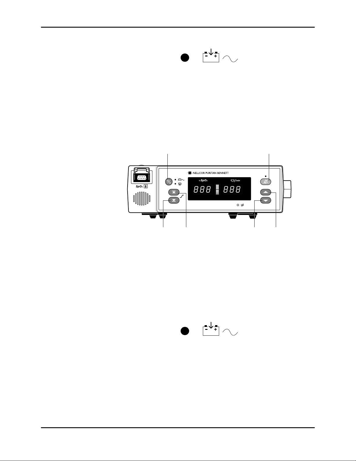
On/Standby Alarm Silence
NPB-190
Note: Refer to Figure 3-1, NPB-190 Controls, when following the instructions
3.3.2.1 Power-On Self-Test
1. Connect the monitor to an AC power source. Verify that the AC
Power/Battery Charging indicator is lit.
2. Do not connect any input cables to the monitor.
3. Observe the monitor front panel. With the monitor off, press the Power
On/Standby button. Verify that the monitor performs the following
sequence:
Lower Alarm
listed below.
Limit
Upper Alarm
Limit
Figure 3-1: NPB-190 Controls
Adjust
Down
Adjust
Up
3-2
Page 15
Section 3: Performance Verification
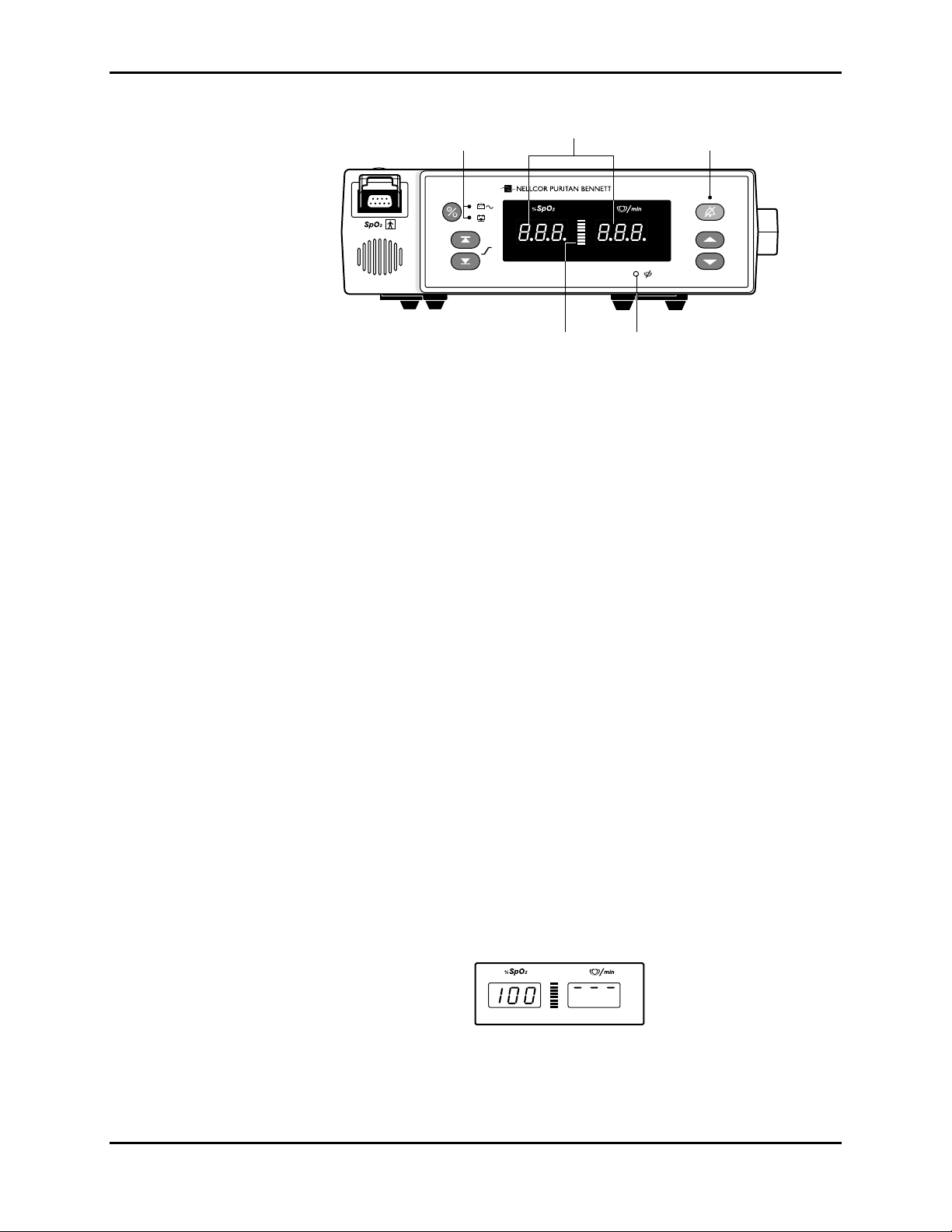
a. All indicators light for a few seconds as illustrated in Figure 3-2.
LEDs
illuminated
888 displayed
10 segments
illuminated
NPB190
LED
illuminated
LED
illuminated
Figure 3-2: Self-Test Display
b. The software version is displayed and the AC Power/Battery Charging
indicators remain on.
c. When a sensor is connected a zero is displayed in each window, a 1-
second Power-On Self-Test (POST) beep sounds and the Pulse Search
LED is illuminated.
If no sensor is connected a 1 second POST beep sounds, 3 dashes are
displayed in each window and the Pulse Search LED is off.
d. The NPB-190 begins normal operation if a sensor is connected.
Without a sensor the monitor will be in the idle mode (3 dashes in each
window).
3.3.2.2 Factory Power-On Defaults and Alarm Limit Ranges
Note: When observing or changing default limits, a 3-second timeout is in
effect, that is, if no action is taken within 3 seconds, the monitor
automatically returns to the normal mode.
1. Turn the monitor on by pressing the Power On/Standby button. Wait for
POST to be completed. Press and release the Upper Alarm Limit button.
Verify that the monitor emits a single beep and the %SpO
a high alarm limit of “100” for about 3 seconds. Verify that three dashes are
displayed at the top of the pulse rate display window.
Note: The location of the three dashes indicates the type of alarm limit that is
being adjusted. Three dashes in the top of the display window indicate a
high alarm limit and three dashes in the bottom of the display window
indicate a low alarm limit.
2 display indicates
Figure 3-3: Adjusting High %SpO2 Alarm Limit
Normal monitoring is resumed after 3 seconds.
3-3
Page 16
Section 3: Performance Verification
2. Press the Upper Alarm Limit button. Press and hold the Adjust Down
button. Verify that the %SpO
Note: A decimal point to the right of the value in either display indicates that
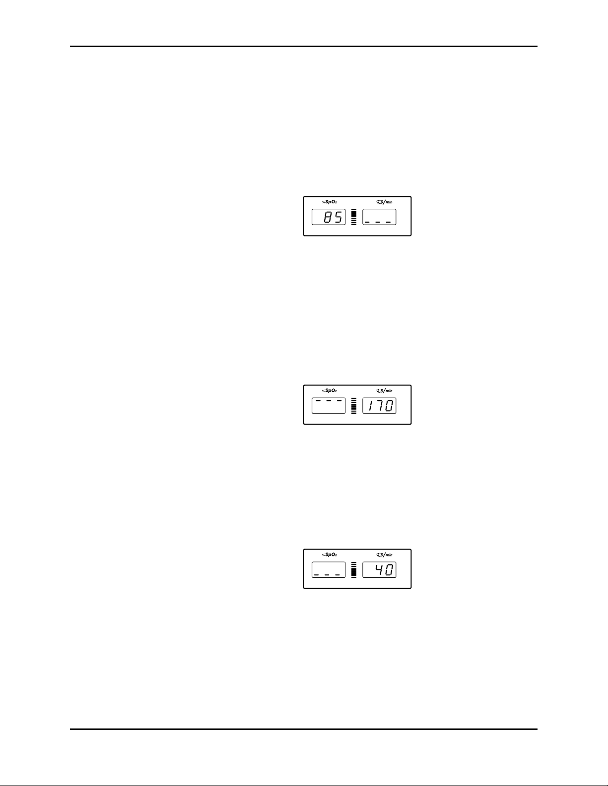
3. Press the Lower Alarm Limit button. Verify that the monitor emits a single
beep and that the %SpO
seconds. Verify that three dashes are displayed at the bottom of the pulse
rate display window.
4. Press the Lower Alarm Limit button. Press and hold the Adjust Down
button and verify that the %SpO
Press and hold the Adjust Up button and verify that the %SpO
cannot be raised past the upper alarm limit setting of “85”.
2 display reduces to a minimum of “85”.
the alarm limits are not power-on default values.
2 display indicates an alarm limit of “85” for 3
Figure 3-4: Adjusting Low %SpO2 Alarm Limit
2 display reduces to a minimum of “20”.
2 display
5. Press the Upper Alarm Limit button two times rapidly (twice within 3
seconds). Verify that the monitor emits two beeps, the pulse rate display
indicates an alarm limit of “170”, and that the %SpO
2 display window
shows three dashes at the top for about 3 seconds.
Figure 3-5: Adjusting High Heart Rate Alarm Limit
6. Press the Upper Alarm Limit button two times rapidly. Press and hold the
Adjust Down button. Verify that the pulse rate display reduces to a
minimum of “40”.
7. Press the Lower Alarm Limit button two times rapidly. Verify that the pulse
rate display indicates an alarm limit of “40” and that the %SpO
2 display
window shows three dashes at the bottom for 3 seconds.
Figure 3-6: Adjusting Low Heart Rate Alarm Limit
3-4
8. Press the Lower Alarm Limit button two times rapidly. Press and hold the
Adjust Down button. Verify that the pulse rate display reduces to a
minimum of “30”.
9. Press the Lower Alarm Limit button two times rapidly. Press and hold the
Adjust Up button and verify that the pulse rate display cannot be adjusted
above “40”.
Page 17

Section 3: Performance Verification
10. Press the Power On/Standby button to turn the unit off. Turn the unit back
on.
11. Press and release the Upper Alarm Limit button. Verify that the %SpO
display indicates an alarm limit of “100”.
12. Press and release the Lower Alarm Limit button. Verify that the %SpO
display indicates an alarm limit of “85”.
13. Press the Upper Alarm Limit button two times rapidly. Verify that the pulse
rate display indicates an alarm limit of “170”.
14. Press the Lower Alarm Limit button two times rapidly. Verify that the pulse
rate display indicates an alarm limit of “40”.
15. Press the Power On/Standby button to turn the monitor off.
3.3.3 Hardware and Software Tests
Hardware and software testing include the following tests:
• Operation with a Pulse Oximeter Tester
• General Operation
3.3.3.1 Operation with a Pulse Oximeter Tester
Operation with an SRC-2 pulse oximeter tester includes the following tests:
• Alarms and Alarm Silence
• Alarm Volume Control
• Pulse Tone Volume Control
• Dynamic Operating Range
• Nurse Call
2
2
3.3.3.1.1 Alarms and Alarm Silence
1. Connect the SRC-2 pulse oximeter tester to the sensor input cable and
connect the cable to the monitor. Set the SRC-2 as follows:
SWITCH POSITION
RATE 38
LIGHT HIGH
MODULATION OFF
RCAL/MODE RCAL 63/LOCAL
2. Press the Power On/Standby button to turn the monitor on. After the normal
power-up sequence, verify that the pulse rate initially indicates zeroes.
Note: The pulse bar may occasionally indicate a step change as the
monitor is in the pulse search mode.
3. Set the modulation switch on the SRC-2 to HIGH.
4. Verify the following monitor reactions:
3-5
Page 18

Section 3: Performance Verification
a. The pulse blip bar begins to track the artificial pulse signal from the
b. The pulse tone is heard.
SRC-2.
c. Zeroes are displayed in the %SpO
2 and pulse rate displays.
d. After about 10 to 20 seconds, the monitor displays oxygen saturation
and pulse rate as specified by the tester. Verify that the values are
within the following tolerances:
Oxygen Saturation Range 79% to 83%
Pulse Rate Range 37 to 39 bpm
e. The audible alarm sounds and both the %SpO
2 and pulse rate displays
flash. This is an indication that both parameters have violated the
default alarm limits.
5. Press and hold the Alarm Silence button on the front of the monitor for less
than 3 seconds. Verify that the pulse rate display indicates “SEC” and the
%SpO
2 display indicates “60” while the Alarm Silence button is pressed.
The alarm is silenced when the button is released.
Figure 3-7: Alarm Silence Duration
6. Release the Alarm Silence button. Verify the following:
a. The alarm remains silenced.
b. The Alarm Silence indicator lights.
c. The %SpO
2 and pulse rate displays resume flashing.
d. The pulse tone is still audible.
e. The audible alarm returns after approximately 60 seconds.
7. While pressing the Alarm Silence button, press the Adjust Down button
until the %SpO
2 display indicates “30”. Press the Adjust Up button and
verify that the displays indicate 60 SEC, 90 SEC, 120 SEC, and OFF.
Release the button when the display indicates “OFF”. Press the Alarm
Silence button again and verify that the Alarm Silence indicator flashes.
8. Wait approximately 3 minutes. Verify that the alarm does not return. After 3
minutes ± 10 seconds, the alarm silence reminder beeps three times, and
continues to do so at 3-minute intervals.
3-6
Page 19

3.3.3.1.2 Alarm Volume Control
After completing the procedure in paragraph 3.3.3.1.1:
1. Press and hold the Alarm Silence button for more than 3 seconds. Verify the
following:
a. “OFF” is displayed for approximately 3 seconds.
b. After 3 seconds, a steady tone is heard at the default alarm volume
setting, the %SpO
indicates the default setting of 5.
2. Press the Adjust Down button until an alarm volume setting of 1 is
displayed. Verify that the volume of the alarm has decreased but is still
audible.
Section 3: Performance Verification
2 display indicates “VOL”, and the pulse rate display
Figure 3-8: Alarm Volume Display
3. Press the Adjust Up button to increase the alarm volume setting to a
maximum value of 10. Verify that the volume increases. Press the Adjust
Down button until a comfortable audio level is attained.
4. Release the Alarm Silence button. The tone stops.
3.3.3.1.3 Pulse Tone Volume Control
1. When a valid pulse has been acquired, press the Adjust Up button and
verify that the beeping pulse tone sound level increases.
2. Press the Adjust Down button and verify that the beeping pulse tone
decreases until it is no longer audible. Press the Adjust Up button to return
the beep volume to a comfortable level.
3.3.3.1.4 Dynamic Operating Range
The following test sequence verifies proper monitor operation over a range of
input signals:
1. Connect the SRC-2 to the NPB-190 and turn the NPB-190 on.
2. Place the SRC-2 in the RCAL 63/LOCAL mode.
3. Set the SRC-2 as indicated in Table 3-1. Verify that the NPB-190 readings
are within the indicated tolerances. Allow the monitor several seconds to
stabilize the readings.
Note: A (*) indicates values that produce an alarm. Press the Alarm Silence
button to silence the alarm.
3-7
Page 20

Section 3: Performance Verification
RATE LIGHT MODULATION SpO2 Pulse Rate
38 HIGH2 LOW 79 - 83* 37 - 39*
112 HIGH1 HIGH 79 - 83* 110 - 114
201 LOW LOW 79 - 83* 198 - 204*
201 LOW HIGH 79 - 83* 198 - 204*
3.3.3.1.5 Nurse Call
Note: The Nurse Call tests must be performed with the instrument operating
1. Connect the negative lead of a voltmeter to pin 10 and positive to pin 11 of
the serial port on the back of the instrument (Figure A-1 in appendix).
Ensure that the audible alarm is not silenced or turned off.
2. Set the SRC-2 to create an alarm condition. Verify an output voltage at pins
10 and 11 between +5 to +12 VDC.
3. Press the Alarm Silence button. With no active audible alarm, the output
voltage at pins 10 and 11 must be between -5 to -12 VDC.
Table 3-1: Dynamic Operating Range
SRC-2 Settings NPB-190 Indications
on AC power.
4. Turn the instrument off. Disconnect the voltmeter and the SRC-2.
3.3.3.1.6 Operation on Battery Power
1. Turn the instrument on using AC Power.
2. Disconnect the instrument from AC and verify that the AC Power Indicator
turns off.
3. Verify that the instrument continues monitoring normally and that the Low
Battery Indicator is not lit.
Note: If the Low Batter Indicator is illuminated, perform the procedure
outlined in step 3.3.1.
4. Connect the instrument to AC and verify that the AC Power Indicator turns
on and that the instrument is monitoring normally.
3.3.3.2 General Operation
The following tests are an overall performance check of the system:
• LED Excitation Test
• Monitor Operation with a Live Subject
3.3.3.2.1 LED Excitation Test
This procedure uses normal system components to test circuit operation. A
Nellcor Oxisensor II
intensity control. The red LED is used to verify intensity modulation caused by
the LED intensity control circuit.
3-8
â
oxygen transducer, model D-25, is used to examine LED
Page 21

Section 3: Performance Verification
1. Connect the monitor to an AC power source.
2. Connect an EC-4 or EC-8 sensor input cable to the monitor.
3. Connect a D-25 sensor to the sensor input cable.
4. Press the Power On/Standby button to turn the monitor on.
5. Leave the sensor open with the LEDs and photodetector visible.
6. After the monitor completes its normal power-up sequence, verify that the
sensor LED is brightly lit.
7. Slowly move the sensor LED in proximity to the photodetector element of
the sensor. Verify, as the LED approaches the photodetector, that the LED
intensity decreases.
8. Open the sensor and notice that the LED intensity increases.
9. Repeat step 7 and the intensity will again decrease. This variation is an
indication that the microprocessor is in proper control of LED intensity.
10. Turn the NPB-190 off.
3.3.3.2.2 Monitor Operation with a Live Subject
Pulse oximetry involves connecting the monitor to a live subject for a qualitative
test.
1. Ensure that the monitor is connected to an AC power source.
2. Connect an EC-4 or EC-8 sensor input cable to the monitor.
3. Connect a Nellcor Durasensor
sensor input cable.
4. Clip the DS-100A to an adult subject as recommended in the sensor
directions for use.
5. Press the Power On/Standby button to turn the monitor on and verify that
the monitor is operating.
6. The monitor should stabilize on the subject’s physiological signal in about
15 to 30 seconds. Verify that the saturation and heart rates are reasonable
for the subject.
3.4 SAFETY TESTS
â
oxygen transducer, model DS-100A, to the
NPB-190 safety tests meet the standards of, and are performed in accordance
with, IEC 601-1 (EN 60601-1, Second Edition, 1988; Amendment 1, 1991-11,
Amendment 2, 1995-03) and UL 2601-1 (August 18, 1994), for instruments
classified as Class 1 and TYPE BF and AAMI Standard ES1 (ANSI/AAMI ES1
1993).
3-9
Page 22

Section 3: Performance Verification
• Ground Integrity
• Electrical Leakage
3.4.1 Ground Integrity
This test checks the integrity of the power cord ground wire from the AC plug to
the instrument chassis ground. The current used for this test is < 6V RMS 50 or
60 Hz and 25 A.
1. Connect the monitor AC mains plug to the analyzer as recommended by the
analyzer operating instructions.
2. Connect the analyzer resistance input lead to the equipotential terminal
(grounding lug) on the rear panel of the instrument. Verify that the analyzer
indicates 100 milliohms or less.
3.4.2 Electrical Leakage
The following tests verify the electrical leakage of the monitor:
• Earth Leakage Current
• Enclosure Leakage Current
• Patient Leakage Current
• Patient Source Current (Mains on Applied Part)
Note: For the following tests, ensure that the AC switch on the rear of the
instrument is configured for the AC voltage being supplied.
3.4.2.1 Earth Leakage Current
This test is in compliance with IEC 601-1 (earth leakage current) and AAMI
Standard ES1 (earth risk current). The applied voltage for AAMI ES1 is 120
VAC 60 Hz, for IEC 601-1 the voltage is 264 VAC 50 to 60 Hz. All
measurements shall be made with the power switch in both the “On” and “Off”
positions.
1. Connect the monitor AC plug to the electrical safety analyzer as
recommended by the analyzer operating instructions.
2. The equipotential terminal is not connected to ground.
AC
POLARITY
Normal Closed Closed 500 µA
Reversed Closed Closed 500 µA
Normal Open Closed 1000 µA
Normal Closed Open 1000 µA
3.4.2.2 Enclosure Leakage Current
LINE CORD NEUTRAL
Table 3-2: Earth Leakage Current Limits
LEAKAGE
CORD
CURRENT
3-10
This test is in compliance with IEC 601-1 (enclosure leakage current) and AAMI
Standard ES1 (enclosure risk current). This test is for ungrounded enclosure
current, measured between enclosure parts and earth. The applied voltage for
Page 23

Section 3: Performance Verification
AAMI/ANSI is
120 VAC 60 Hz, and for IEC 601-1 the applied voltage is 264 VAC 50 to 60 Hz.
1. Connect the monitor AC plug to the electrical safety analyzer as
recommended by the analyzer operating instructions.
2. Place a 200 cm
is not in contact with any metal parts of the enclosure that may be grounded.
Measure the leakage current between the foil and earth.
The analyzer leakage indication must not exceed values listed in the table below:
Table 3-3: Enclosure Leakage Current Limits
AC LINE
CORD
Closed Closed Closed 100 µA 100 µA
Closed Closed Open 500 µA 300 µA
Closed Open Closed 500 µA 300 µA
Open Closed Closed 500 µA 100 µA
Open Open Closed 500 µA 300 µA
Open Closed Open 500 µA 300 µA
3.4.2.3 Patient Applied Risk Current
NEUTRAL
LINE CORD
This test is in compliance with AAMI Standard ES1 (patient applied risk
current), and IEC 601-1 (patient auxiliary current). The leakage current is
measured between any individual patient connection and power (earth) ground.
The applied voltage for AAMI/ANSI is 120 VAC 60 Hz, and for IEC 601-1 the
applied voltage is 264 VAC 50 to 60 Hz.
2
foil in contact with the instrument case making sure the foil
POWER LINE
GROUND CABLE
IEC 601-1 AAMI/ANSI ES1
STANDARD
1. Configure the electrical safety analyzer as follows:
Function: Patient Leakage
Range: µA
2. Connect the monitor AC plug to the electrical safety analyzer as
recommended by the analyzer operating instructions for Patient Leakage
Current.
3. Connect the electrical safety analyzer patient leakage input lead to all pins
of the monitor's patient cable at the end of the cable.
4. The equipotential terminal is not connected to ground.
5. All functional earth terminals are not connected to ground.
6. Measure the leakage current between the patient connector and earth.
3-11
Page 24

Section 3: Performance Verification
Table 3-4: Patient Leakage Current Limits
AC LINE
POLARITY
Normal Closed Closed 100 µA 10 µA
Normal Open Closed 500 µA 50 µA
Normal Closed Open 500 µA 50 µA
Reverse Closed Closed 100 µA 10 µA
Reverse Open Closed 500 µA 50 µA
Reverse Closed Open 500 µA 50 µA
3.4.2.4 Patient Isolation Risk Current - (Mains Voltage on the Applied Part)
NEUTRAL
LINE
POWER LINE
GROUND
CABLE
IEC 601-1 AAMI/ANSI
This test is in compliance with AAMI Standard ES1 (patient isolation risk
current [sink current]), and IEC 601-1 (patient leakage current). Patient Leakage
Current is the measured value in a patient connection if mains voltage is
connected to that patient connection. The applied voltage for AAMI/ANSI is 120
VAC 60 Hz, and for IEC 601-1 the applied voltage is 264 VAC 50 to 60 Hz.
Warning: AC mains voltage will be present on the patient applied part
terminals during this test. Exercise caution to avoid electrical shock hazard.
1. Configure the electrical safety analyzer as follows:
Function: Patient Leakage (Mains On Applied Part)
Range: µA
ES1
STANDARD
2. Connect the monitor AC plug to the electrical safety analyzer as
recommended by the operating instructions for patient sink (leakage)
current.
3. Connect the electrical safety analyzer patient leakage input lead to all
connectors in the patient cable at the patient end of the cable.
4. The equipotential terminal is not connected to ground.
5. All functional earth terminals are not connected to ground.
6. The analyzer leakage current must not exceed the values shown in the table
below.
Table 3-5: Patient Leakage Current Test Configurations -
Mains Voltage on the Applied Part
AC LINE
POLARITY
Normal Closed Closed 5 mA 50 µA
Reverse Closed Closed 5 mA 50 µA
NEUTRAL
LINE
POWER
LINE
GROUND
CABLE
IEC 601-1 AAMI/ANSI
ES1
STANDARD
3-12
Page 25
SECTION 4: AUDIBLE ALARM SETTINGS & SERVICE MENU
4.1 Introduction
4.2 Audible Alarm Settings
4.3 Service Menu
4.1 INTRODUCTION
This section discusses use of the service menu to reconfigure power-on default
values, and how to control the behavior of the audible alarm.
4.2 AUDIBLE ALARM SETTINGS
The following paragraphs describe how to change the behavior of the audible
alarm. Operators can select the volume of the alarm and the duration of alarm
silence. Controls for the NPB-190 are shown in Figure 4-1.
On/Standby Alarm silence
NPB190
4.2.1 Alarm Silence State
Press the Alarm Silence button to silence the alarm. Press the button a second
time to turn the alarm back on.
4.2.2 Alarm Silence Duration
1. Press and hold the Alarm Silence button for less than 3 seconds.
2. Before 3 seconds have passed the Adjust Up or Adjust Down button can be
used to change the duration of the alarm silence. The alarm’s duration can
be 30, 60, 90, 120 seconds, or the alarm can be turned off.
4.2.3 Alarm Volume
1. Press and hold the Alarm Silence button for more than 3 seconds.
Set lower
limit
Set upper
limit
Figure 4-1: NPB-190 Controls
Adjust
down
Adjust
up
4-1
Page 26

Section 4: Audible Alarm Settings & Service Menu
2. After 3 seconds, while still pressing the Alarm Silence button, the Adjust
Up or Adjust Down button can be used to select alarm volumes from 1 to
10. Select a level that is suitable for the monitor’s location.
4.3 SERVICE MENU
The menu items listed below should be accessed only by a qualified service
technician. Power-on default values can be changed for the behavior of the
audible alarm, alarm limits, and for the serial port.
4.3.1 Accessing Menu Items
1. Menu items can be accessed at any time by pressing the Upper and Lower
Alarm Limit buttons simultaneously for at least 3 seconds. The service
menu has been accessed when a 1 appears in the pulse rate display.
2. Pressing the Adjust Up or Adjust Down button selects the menu item
number. Menu numbers 5 and 6, have items within them that can be selected
by first pressing the Upper Alarm Limit button, and then pressing the Adjust
Up or Adjust Down key.
Note: Service menu items greater than 2 cannot be accessed if a sensor is
connected to the monitor.
3. Once adjustments have been made within a menu item the, Upper Alarm
Limit button can be used to initiate the current selection. Three tones will
sound to indicate that the change has been accepted, and the monitor will
return to normal monitoring.
4. The service menu can be exited without making changes by pressing the
Lower Alarm Limit button. If a period of 10 seconds passes with no button
presses, the instrument will exit the service menu, go to normal monitoring,
and no changes will have been made.
4.3.2 Menu Item 1 (Save Current Values as Power-On Default)
1. If menu item 1 is selected, the current values for alarm limits, alarm volume,
pulse beep volume, audible alarm silence duration, alarm silence behavior,
and baud rate will be saved as the power-on default settings. Some values
are not allowed to be saved as power on default values, they are; an Alarm
Silence Duration of Off, and low %SpO
invalid tone is heard instead of the triple beep the current settings were not
changed.
Note: Current values will not be stored in memory as defaults, if power is
interrupted before exiting this menu option.
Note: When the operator changes an alarm limit to a value other than a power
on default value, a decimal point will appear to the right of the parameter
whose alarm limit was changed.
2 alarm limits less than 80%. If an
4-2
Page 27

4.3.3 Menu Item 2 (Return to Default Settings)
Menu item 2 resets the monitor to factory default settings as shown in table 4-1.
Table 4-1: Factory Default Settings
Parameter Default Value
SpO2 High 100%
SpO2 Low 85%
Pulse rate High 170 bpm
Pulse rate Low 40 bpm
Pulse beep volume Level 4
Alarm Volume Level 5
Alarm Silence Duration 60 seconds
Alarm Silence Behavior 0 (Off with reminder)
Baud Rate 9600
Note: Menu items greater than 2 cannot be accessed when a valid sensor is
plugged into the unit.
Note: To reach menu item 5 two invalid tones will be heard when passing
through menu items 3 and 4.
Section 4: Audible Alarm Settings & Service Menu
4.3.4 Menu Item 3 (Not Displayed)
4.3.5 Menu Item 4 (Not Displayed)
4.3.6 Menu Item 5 (Alarm Silence Behavior)
1. This menu item is used to change alarm silence behavior. Three options; 0,
1, or 2 can be accessed by first pressing the Upper Alarm Limit button, then
using the Adjust Up or Down button to scroll to the desired number.
2. Option “0” will allow the operator to select Alarm Silence, but there will be
a reminder tone every 3 minutes.
3. Option “1” allows the operator to select Alarm Silence and there will be no
reminder tone.
4. Option “2” will not allow the operator to select Alarm Silence.
5. When the desired option is indicated in the display, press the Upper Alarm
Limit button to save the current selection. Three tones will sound to indicate
that the change has been accepted
Note: The low battery audible alarm cannot be disabled.
4.3.7 Menu Item 6 (Baud Rate)
1. Baud rates of 2400, 9600, and 19200 can be selected by first pressing the
Upper Alarm Limit button, then using the Adjust Up or Adjust Down button
to select the desired baud rate. The baud rates will be displayed in the
%SpO
2 window as 24, 96, or 192.
4-3
Page 28

Section 4: Audible Alarm Settings & Service Menu
2. When the desired option is indicated in the display, press the Upper Alarm
Limit button to save the current selection. Three tones will sound to indicate
that the change has been accepted.
4.3.8 Menu Item 7
Do not use. For use by Mallinckrodt Customer Service Engineer.
4.3.9 Menu Item 8
Do not use. For use by Mallinckrodt Customer Service Engineer.
4.3.10 Menu Item 9
Do not use. For use by Mallinckrodt Customer Service Engineer.
4-4
Page 29

SECTION 5: TROUBLESHOOTING
5.1 Introduction
5.2 How to Use this Section
5.3 Who Should Perform Repairs
5.4 Replacement Level Supported
5.5 Obtaining Replacement Parts
5.6 Troubleshooting Guide
5.7 Error Codes
5.1 INTRODUCTION
This section explains how to troubleshoot the NPB-190 if problems arise. Tables
are supplied that list possible monitor difficulties, along with probable causes,
and recommended actions to correct the difficulty.
5.2 HOW TO USE THIS SECTION
Use this section in conjunction with Section 3, Performance Verification, and
Section 7, Spare Parts. To remove and replace a part you suspect is defective,
follow the instructions in Section 6, Disassembly Guide. The circuit analysis
section in the Technical Supplement offers information on how the monitor
functions.
5.3 WHO SHOULD PERFORM REPAIRS
Only qualified service personnel should open the monitor housing, remove and
replace components, or make adjustments. If your medical facility does not have
qualified service personnel, contact Mallinckrodt Technical Services or your
local Mallinckrodt representative.
5.4 REPLACEMENT LEVEL SUPPORTED
The replacement level supported for this product is to the printed circuit board
(PCB) and major subassembly level. Once you isolate a suspected PCB, follow
the procedures in Section 6, Disassembly Guide, to replace the PCB with a
known good PCB. Check to see if the symptom disappears and that the monitor
passes all performance tests. If the symptom persists, swap back the replacement
PCB with the suspected malfunctioning PCB (the original PCB that was installed
when you started troubleshooting) and continue troubleshooting as directed in
this section.
5.5 OBTAINING REPLACEMENT PARTS
Mallinckrodt Technical Services provides technical assistance information and
replacement parts. To obtain replacement parts, contact Mallinckrodt or your
local Mallinckrodt representative. Refer to parts by the part names and part
numbers listed in Section 7, Spare Parts.
5-1
Page 30

Section 5: Troubleshooting
5.6 TROUBLESHOOTING GUIDE
Problems with the NPB-190 are separated into the categories indicated in Table
5-1. Refer to the paragraph indicated for further troubleshooting instructions.
Note: Taking the recommended actions discussed in this section will correct
the majority of problems you will encounter. However, problems not
covered here can be resolved by calling Mallinckrodt Technical
Services or your local representative.
Problem Area Refer to Paragraph
1. Power
• No power-up on AC and/or DC
• Fails power-on self-test
• Powers down without apparent cause
2. Buttons
• Monitor does not respond properly to
buttons
3. Display/Alarms
• Displays do not respond properly
• Alarms or other tones do not sound
properly or are generated without apparent
cause
4. Operational Performance
• Displays appear to be operational, but
monitor shows no readings
• Suspect readings
5. Serial Port
• NPB-190 and PC not communicating
properly
• Nurse Call not functioning properly
Table 5-1: Problem Categories
5.6.1
5.6.2
5.6.3
5.6.4
5.6.5
5-2
All of the categories in Table 5-1 are discussed in the following paragraphs.
Page 31

5.6.1 Power
Section 5: Troubleshooting
Power problems are related to AC and/or DC. Table 5-2 lists recommended
actions to power problems.
Table 5-2: Power Problems
Condition Recommended Action
1. BATTERY LOW
indicator lights
steadily while NPB190 is connected to
AC and battery is
fully charged.
2. The NPB-190 does
not operate when
disconnected from
AC power.
3. BATTERY LOW
indicator on during
DC operation and
an alarm is
sounding.
1. Ensure that the NPB-190 is plugged into an operational AC
outlet and the AC indicator is on.
2. Check the fuses. The Power Entry Module contains the
fuses as indicated in paragraph 6.3 and Figure 6-3 of the
Disassembly Guide section. Replace if necessary.
3. Open the monitor as described in section 6. Verify power
supply’s output to the battery while on AC. Disconnect the
battery leads from the battery and connect a DVM to them.
The voltage measured should be 6.8 VDC + 0.15 and the
current should be 400 mA + 80 mA. Replace power supply
if above values are not met.
4. Check the cable connection from the bottom enclosure to
the UIF PCB, as instructed in paragraph 6.5 of the
Disassembly Guide section. If the connection is good,
replace the UIF PCB.
1. The battery may be discharged. To recharge the battery,
refer to paragraph 3.3.1, Battery Charge. The monitor may
be used with a less than fully charged battery but with a
corresponding decrease in operating time from that charge.
2. If the battery fails to hold a charge, replace the battery as
indicated in Section 6, Disassembly Guide.
There are 15 minutes or less of usable charge left on the
NPB-190 battery before the instrument shuts off. At this
point, if possible, cease use of the NPB-190 on battery
power, connect it to an AC source, and allow it to recharge.
The full recharge takes 14 hours. The NPB-190 may
continue to be used while it is recharging.
4. Battery does not
charge.
1. Replace battery if more than 2 years old.
2. Open the monitor as described in Section 6. Verify power
supply’s output to the battery while on AC. Disconnect the
battery leads from the battery and connect a DVM to them.
The voltage measured should be 6.8 VDC ± 0.15 and the
current should be 400 mA ± 80 mA. Replace power supply
if above values are not met.
5-3
Page 32

Section 5: Troubleshooting
5.6.2 Buttons
Table 5-3 lists symptoms of problems relating to nonresponsive buttons and
recommended actions. If the action requires replacement of a PCB, refer to
Section 6, Disassembly Guide.
Condition Recommended Action
1. The NPB-190 responds
to some, but not all
buttons.
Table 5-3: Button Problems
1. Replace Top Housing assembly.
2. If the buttons still do not work, replace the UIF PCB.
5.6.3 Display/Alarms
2. The NPB-190 turns on
but does not respond to
any of the buttons.
1. Check the connection between the membrane panel
and J5 of the UIF PCB.
2. Replace Top Housing assembly.
3. If the buttons still do not work, replace the UIF PCB.
Table 5-4 lists symptoms of problems relating to nonfunctioning displays,
audible tones or alarms, and recommended actions. If the action requires
replacement of a PCB or module, refer to Section 6, Disassembly Guide.
Table 5-4: Display/Alarms Problems
Condition Recommended Action
1. Display values are
missing or erratic.
1. Try another sensor or relocate the sensor to a
different site.
2. If the sensor is connected, replace the sensor
connector assembly.
3. If the condition persists, replace the sensor
extension cable.
4. If the condition still persists, replace the UIF
PCB.
5-4
2. All display segments
do not light during
POST.
3. All Front Panel LED
indicators do not light
during POST.
4. Alarm sounds for no
apparent reason.
1. Check the connection between the UIF PCB and
the Display PCB.
2. If the condition does not change, replace the
Display PCB.
3. If the condition still persists, replace the UIF
PCB.
1. Check the connection between the membrane
panel and J5 of the UIF PCB.
2. Replace Top Housing assembly.
1. Moisture or spilled liquids can cause an alarm to
sound. Allow the monitor to dry thoroughly
before using.
2. If the condition persists, replace the UIF PCB.
Page 33

Section 5: Troubleshooting
Table 5-4: Display/Alarms Problems (cont. from page 5-4)
Condition Recommended Action
5. Alarm does not sound. 1. Check speaker connection to UIF PCB.
2. Replace the speaker as described in Section 6,
Disassembly Guide.
3. If the condition persists, replace the UIF PCB.
Table 5-5 lists symptoms of problems relating to operational performance (no
error codes displayed) and recommended actions. If the action requires
replacement of a PCB or module, refer to Section 6, Disassembly Guide.
Table 5-5: Operational Performance Problems
Condition Recommended Action
1. The Pulse Amplitude
indicator seems to
indicate a pulse, but the
digital displays show
zeroes.
2. SpO2 or pulse rate values
change rapidly; Pulse
Amplitude indicator is
erratic.
1. The sensor may be damaged; replace it.
2. If the condition still persists, replace the UIF
PCB.
1. The sensor may be damp or may have been
reused too many times. Replace it.
2. An electrosurgical unit (ESU) may be
interfering with performance:
ñ Move the NPB-190 and its cables and
sensors as far from the ESU as possible.
ñ Plug the NPB-190 and the ESU into
different AC circuits.
ñ Move the ESU ground pad as close to the
surgical site as possible and as far away
from the sensor as possible.
3. Verify performance with the procedures
detailed in Section 3.
4. If the condition still persists, replace the UIF
PCB.
5-5
Page 34

Section 5: Troubleshooting
5.6.5 Serial Port
Table 5-6 lists symptoms of problems relating to the serial port and
recommended actions. If the action requires replacement of the PCB, refer to
Section 6, Disassembly Guide.
Condition Recommended Action
Table 5-6: Serial Port Problems
1. No printout is being
received.
2. The Nurse Call function
is not working.
1. The unit is running on battery power.
Connect to an AC source. If the AC indicator
is not on see section 5.6.1.
2. The monitor’s baud rate does not match the
printer. Change the baud rate of the monitor
following instructions in section 4.3.7.
3. Check connections between serial port and
printer (see section A3).
4. If the condition still persists, replace the UIF
PCB.
1. The unit is running on battery power.
Connect to an AC source. If the AC indicator
is not on see section 5.6.1.
2. Verify that connections are made between
pins 5 or 10 (GND) and 11 (Nurse Call) of
the serial port.
3. Verify that output voltage between ground
pin 5 or 10 and pin 11 is -5 to -12 VDC (no
alarm) and +5 to +12 VDC (during alarm).
4. If the condition still persists, replace the UIF
PCB.
5-6
Page 35

5.7 ERROR CODES
Section 5: Troubleshooting
An error code will be displayed when the NPB-190 detects a non-correctable
failure. When this occurs, the unit will stop monitoring, sound a low priority
alarm that cannot be silenced, clear patient data from the display, and display an
error code. Error codes will be displayed with EEE in the Saturation display and
the number of the code in the Pulse Rate display, i.e., EEE 1. Table 5-7 provides
a complete list of error codes and possible solutions.
Table 5-7: Error Codes
Code Meaning Possible Solutions
POST failure Replace UIF PCB
1
Battery dead 1. Check the voltage selector
4
switch.
2. Charge battery for 14 hours
3. Leads of battery reversed;
see paragraph 6.5
4. Replace battery
Too many microprocessor resets
5
within a period of time
Boot CRC error Replace UIF PCB
6
Error on UIF PCB 1. Cycle power to clear error.
7
1. Replace UIF PCB
2. Replace Power Supply
2. Check voltage selector
switch for proper setting.
3. Replace UIF PCB
Flash ROM corruption Replace UIF PCB
11
Error accessing EEPROM Replace UIF PCB
76
Institutional default values lost
80
Replace UIF PCB
and reset to factory default
values
Internal communications error Replace UIF PCB
84
5-7
Page 36

Page 37

SECTION 6: DISASSEMBLY GUIDE
6.1 Introduction
6.2 Prior to Disassembly
6.3 Fuse Replacement
6.4 Monitor Disassembly
6.5 Monitor Reassembly
6.6 Battery Replacement
6.7 Power Entry Module (PEM) Removal/Installation
6.8 Power Supply Removal/Installation
6.9 Display PCB Removal/Installation
6.10 UIF PCB Removal/Installation
6.11 Alarm Speaker Removal/Installation
6.1 INTRODUCTION
The NPB-190 can be disassembled down to all major component parts,
including:
• PCBs
• Battery
• Top and Bottom Housing
• Speaker
• Power Entry Module (PEM)
The following tools are required:
• Phillips-head screwdriver #1
• 10 mm open-end wrench
• Needle-nose pliers
• Torque wrench, 10 inch-pounds (1.13 newton-meters)
• Wire Cutters
WARNING: Before attempting to open or disassemble the NPB-190,
disconnect the power cord from the NPB-190.
Caution: Observe ESD (electrostatic discharge) precautions when working
within the unit.
Note: Some spare parts have a business reply card attached. When you receive
these spare parts, please fill out and return the card.
6.2 PRIOR TO DISASSEMBLY
1. Turn the NPB-190 off by pressing the Power On/Standby button.
2. Disconnect the monitor from the AC power source.
6-1
Page 38

Section 6: Disassembly Guide
6.3 FUSE REPLACEMENT
1. Complete the procedure in paragraph 6.2.
2. Disconnect the power cord from the back of the monitor.
3. Remove the fuse drawer from the Power Entry Module by pressing down on
the tab in the center and pulling the drawer out as shown in Figure 6-1.
Figure 6-1: Fuse Removal
4. Put new 0.5 amp fuses in the drawer and reinsert the drawer in the power
module.
6-2
Page 39

6.4 MONITOR DISASSEMBLY
Caution: Observe ESD (electrostatic discharge) precautions when
disassembling and reassembling the NPB-190 and when handling any of the
components of the
NPB-190.
1. Set the NPB-190 upside down, as shown in Figure 6-2.
Section 6: Disassembly Guide
Corner screws
Figure 6-2: NPB-190 Corner Screws
2. Remove the four corner screws.
3. Turn the unit upright. Separate the top case from the bottom case of the
monitor being careful not to stress the wire harnesses between the cases.
Place the two halves of the monitor on the table as shown in Figure 6-3.
4. Disconnect the Power Supply from J6 on the UIF PCB.
6-3
Page 40

Section 6: Disassembly Guide
J6
Power supply
harness
6.5 MONITOR REASSEMBLY
1. Place the two halves of the monitor on the table as shown in Figure 6-3 and
connect the Power Supply to J6 on the UIF PCB.
2. Place the top case over the bottom case and align the four outside screw
posts and close the monitor.
Caution: When reassembling the NPB-190, hand tighten the screws that
hold the cases together to a maximum of 10 inch-pounds. Over-tightening
could strip out the screw holes in the top case, rendering them unusable.
3. Install the four corner screws.
6-4
Figure 6-3: Separating Case Halves
Page 41

6.6 BATTERY REPLACEMENT
Removal
1. Follow procedure in paragraphs 6.2 and 6.4.
2. Remove the two screws from the battery bracket shown in Figure 6-4 and
lift the battery out of the bottom case.
3. Use needle-nose pliers to disconnect the leads from the battery.
Section 6: Disassembly Guide
Figure 6-4: Battery Removal
4. The lead-acid battery is recyclable. Do not dispose of the battery by placing
it in the regular trash. Dispose of properly according to state, local or other
applicable regulations, or contact Mallinckrodt Technical Services to return
for disposal.
Installation
5. Connect the leads to the battery. The red wire connects to the positive
terminal and the black wire goes to the negative.
6. Insert the new battery into the bottom case with the negative terminal
towards the bottom of the monitor. Install the bracket and grounding lead
with the two screws.
7. Complete the procedure in paragraph 6.5.
6-5
Page 42

Section 6: Disassembly Guide
8. Turn the monitor on and verify proper operation.
6.7 POWER ENTRY MODULE (PEM) REMOVAL/INSTALLATION
Removal
1. Complete the procedure in paragraphs 6.2 and 6.4.
2. While pushing the top of the PEM in from the outside of the case, gently
push the case to the outside and lift up on the PEM.
3. Use needle-nose pliers to disconnect the leads from the PEM (see Figure 6-
5).
N
G
L
6-6
Figure 6-5: Power Entry Module
Installation
4. Reconnect the three leads. The blue “N” wire, from the power supply goes
to the terminal labeled “N” on the PEM. The brown “L” wire, from the
power supply connects to the terminal labeled “L” on the PEM. The center
terminal at the top of the PEM is for the ground wire (Figure 6-6).
5. Install the PEM in the bottom case with the fuse drawer facing down. A tab
in the bottom case holds the PEM in place. Insert the bottom wing of the
PEM between the tab and the internal edge of the side wall of the bottom
case. Push the PEM down and towards the outside of the monitor until it
clicks into place.
Page 43

6. Position the ground line from the PEM so that it does not come into contact
with components on the Power Supply PCB.
7. Complete procedure in paragraph 6.5.
6.8 POWER SUPPLY REMOVAL/INSTALLATION
Removal
1. Complete the procedure described in paragraphs 6.2 and 6.4.
2. Disconnect the leads from the battery.
3. Follow the procedure in paragraph 6.7, steps 2 and 3.
4. Use a 10mm wrench to disconnect the Power Supply ground lead from the
equipotential lug (Figure 6-6).
5. Remove the seven screws shown in Figure 6-7.
Section 6: Disassembly Guide
6. Lift the Power Supply out of the bottom case.
W1
to
Equipotential
Lug
G
LN
Brown to
"L" on
PEM
W2
Equipotential
Lug
W3
Blue to
"N" on
PEM
W5
W4
Black
Red
Figure 6-6: Power Supply Leads Connections
6-7
Page 44

Section 6: Disassembly Guide
Figure 6-7: Power Supply
Installation
7. Reconnect the AC leads. The wire from the Power Supply labeled “N” goes
to the terminal labeled “N” on the PEM. The wire from the power supply
labeled “L” connects to the terminal labeled “L” on the PEM.
8. Place the Power Supply in the bottom case.
Caution: When installing the Power Supply, tighten the seven screws to a
maximum of 10 inch-pounds. Overtightening could strip out the inserts in
the bottom case, rendering them unusable.
9. Install the seven screws in the Power Supply and tighten.
10. Use a 10mm wrench to connect the power supply ground lead to the
equipotential lug. Tighten to 12 inch pounds.
11. Follow the procedure in paragraph 6.7, step 5.
12. Connect the ground wire to the PEM and position it so that it does not come
into contact with components on the Power Supply PCB.
6-8
13. Complete the procedure in paragraph 6-5.
Page 45

6.9 DISPLAY PCB REMOVAL/INSTALLATION
Removal
1. Complete the procedure described in paragraphs 6.2 and 6.4.
2. Lift the Display PCB up to remove it from the top case (Figure 6-8).
Grounding clip
Section 6: Disassembly Guide
J4
Figure 6-8: Display PCB
Installation
3. Slide the Display PCB into the grooves in the top case, being careful to
align the male pins from the Display PCB to connector J4 on the UIF PCB.
4. Complete the procedure in paragraph 6.5.
6-9
Page 46

Section 6: Disassembly Guide
6.10 UIF PCB REMOVAL/INSTALLATION
Removal
1. Complete the procedure described in paragraphs 6.2 and 6.4.
2. Lift the Display PCB up to remove it from the top case (Figure 6-8).
3. Disconnect the keypad ribbon cable from J5 of the UIF PCB (Figure 6-8).
J5 is a ZIF connector, lift up on the outer shell until it clicks, then remove
the ribbon cable from the connector.
4. Disconnect the speaker cable from J3 of the UIF PCB.
5. Remove the five screws in the UIF PCB (Figure 6-9).
J3
J5
6-10
Figure 6-9: UIF PCB
6. Remove the UIF PCB from the top case.
Page 47

Installation
Caution: When installing the UIF PCB, hand-tighten the five screws to a
maximum of 10 inch-pounds. Overtightening could strip out the inserts in
the top case, rendering them unusable.
7. Place the UIF PCB in the top case.
8. Install the five screws in the UIF PCB.
9. Lift up on the outer shell of J5 on the UIF PCB until it clicks. Insert the
keypad ribbon cable into J5 of the UIF PCB. Slide the outer shell of J5
down until it clicks.
10. Connect the speaker cable to J3 of the UIF PCB.
11. Slide the Display PCB into the grooves in the top case being careful to align
the male pins from the Display PCB to connector J4 on the UIF PCB.
12. Complete the procedure in paragraph 6.5.
6.11 ALARM SPEAKER REMOVAL/INSTALLATION
Removal
Section 6: Disassembly Guide
1. Complete the procedure described in paragraphs 6.2 and 6.4.
2. Disconnect the speaker wire harness for J3 on the UIF PCB (see Figure 6-
10).
3. Pull the holding clip towards the center of the monitor and lift the speaker
from the top housing.
6-11
Page 48

Section 6: Disassembly Guide
Connect speaker
wires to J3 connector
Figure 6-10: Alarm Speaker
Installation
4. Slide the speaker into the plastic holding clip provided in the top housing.
5. Connect the speaker wire harness to J3 on the UIF PCB.
6. Complete the procedure paragraph 6.5.
6-12
Page 49

SECTION 7: SPARE PARTS
7.1 Introduction
7.1 INTRODUCTION
Spare parts, along with part numbers, are shown below. Item numbers
correspond to the numbers called out in Figure 7-1.
Item Description Part No.
1 Top Case Assembly (Membrane Panel Included) 048428
2 Fuse Drawer 691500
3 Fuses 691032
4 Power Entry Module 691499
5 Power Supply 035200
6 Display PCB 035196
7 Battery 640119
8 Battery Bracket 035307
9 UIF PCB 035192
Sensor Lock (not shown) 022943
Alarm Speaker (not shown) 033494
Ground Clip (not shown) 035400
Rubber Feet (not shown) 4-003818-00
Power Cord (not shown) U.S. 071505
International 901862
U.K. 901863
Figure 7-1 shows the NPB-190 expanded view with item numbers relating to the
spare parts list.
Note: Some spare parts have a business reply card attached. When you receive
these spare parts, please fill out and return the card.
7-1
Page 50

Section 7: Spare Parts
1
9
NPB190
2
8
7
6
3
4
5
Figure 7-1: NPB-190 Exploded View
7-2
Page 51

SECTION 8: PACKING FOR SHIPMENT
8.1 General Instructions
8.2 Repacking in Original Carton
8.3 Repacking in a Different Carton
To ship the monitor for any reason, follow the instructions in this section.
8.1 GENERAL INSTRUCTIONS
Pack the monitor carefully. Failure to follow the instructions in this section may
result in loss or damage not covered by the Mallinckrodt warranty. If the original
shipping carton is not available, use another suitable carton; North American
customers may call Mallinckrodt Technical Services Department to obtain a
shipping carton.
Before shipping the NPB-190, contact Mallinckrodt Technical Services
Department for a returned goods authorization (RGA) number. Mark the
shipping carton and any shipping documents with the RGA number. European
customers not using RGA numbers, should return the product with a detailed,
written description of the problem.
8.2 REPACKING IN ORIGINAL CARTON
If available, use the original carton and packing materials. Pack the monitor as
follows:
1. Place the monitor in a plastic bag (not shown) and, if necessary, accessory
items in original packaging.
8-1
Page 52

Section 8: Packing for Shipment
8-2
Figure 8-1: Repacking the NPB-190
2. Place in shipping carton and seal carton with packaging tape.
3. Label carton with shipping address, return address and RGA number.
Page 53

8.3 REPACKING IN A DIFFERENT CARTON
If the original carton is not available, use the following procedure to pack the
NPB-190:
1. Place the monitor in a plastic bag.
2. Locate a corrugated cardboard shipping carton with at least 200 pounds per
square inch (psi) bursting strength.
3. Fill the bottom of the carton with at least 2 inches of packing material.
4. Place the bagged unit on the layer of packing material and fill the box
completely with packing material.
5. Seal the carton with packing tape.
6. Label the carton with the shipping address, return address, and RGA
number.
Section 8: Packing for Shipment
8-3
Page 54

Page 55

SECTION 9: SPECIFICATIONS
9.1 General
9.2 Electrical
9.3 Physical Characteristics
9.4 Environmental
9.5 Alarms
9.6 Factory Default Settings
9.7 Performance
9.1 GENERAL
Designed to meet safety requirements of:
UL 2601-1 CSA-C22.2 No. 601-1-M90, IEC 601-1 (Class I, type BF)
EMC per EN60601-1-2
9.2 ELECTRICAL
Protection Class
Class I: per IEC 601-1, clause 2.2.4
Degree of Protection
Type BF: per IEC 601-1, clause 2.2.25
Mode of Operation
Continuous
Battery
Type Rechargeable, sealed lead-acid, internal
Operating time 12 hours minimum on new, fully charged
battery
Recharge period 14 hours for full charge
Fuses 2 each 5 X 20 mm
Slow Blow. 0.5 amp, 250 volts
AC Power
Selectable by switch 100-120 VAC 50/60 Hz or
200-240 VAC 50/60 Hz
9-1
Page 56

Section 9: Specifications
9.3 PHYSICAL CHARACTERISTICS
Dimensions 3.3 in H x 10.4 in W x 6.8 in D
Weight 5.5 lb
9.4 ENVIRONMENTAL
Operating Temperature 5°C to 40°C (+41°F to +104°F)
Storage Temperature
Boxed -20°C to +70°C (-4°F to +158°F)
Unboxed -20°C to +60°C (-4°F to +140°F)
Operating Atmospheric Pressure 700 hPa to 1060 hPa
Relative Humidity 15% RH to 95% RH, noncondensing
8.4 cm H x 26.4 cm W x 17.3 cm D
2.5 kg
(20.65 inHg to 31.27 inHg)
9.5 ALARMS
Alarm Limit Range
% Saturation 20–100%
Pulse Rate 30–250 bpm
9.6 FACTORY DEFAULT SETTINGS
Parameter Default Setting
SpO2 High Alarm 100%
SpO2 Low Alarm 85%
High pulse rate Alarm 170 bpm
Low pulse rate Alarm 40 bpm
Audible Alarm Volume Level 5
Audible Alarm Silence Duration 60 seconds
Pulse Beep Volume Level 4
Communication Protocol Serial output mode ASCII
Alarm Silence Behavior Off with a reminder
Baud Rate 9600
9-2
Page 57

9.7 PERFORMANCE
Measurement Range
SpO2: 0–100%
Pulse/Heart Rate: 20–250 bpm
Accuracy
SpO
Adult: 70–100% ± 2 digits
Neonate: 70–100% ± 3 digits
Accuracies are expressed as plus or minus “X” digits (saturation percentage
points) between saturations of 70-100%. This variation equals plus or minus one
standard deviation (1SD), which encompasses 68% of the population. All
accuracy specifications are based on testing the subject monitor on healthy adult
volunteers in induced hypoxia studies across the specified range. Adult accuracy
is determined with Oxisensor II D-25 sensors. Accuracy for neonatal readings is
determined with Oxisensor II N-25 sensors. In addition, the neonatal accuracy
specification is adjusted to take into account the theoretical effect of fetal
hemoglobin in neonatal blood on oximetry measurements.
Section 9: Specifications
2
0–69% unspecified
0–69% unspecified
Pulse Rate (optically derived) 20–250 bpm ± 3 bpm
Accuracies are expressed as plus or minus “X” bpm across the display range.
This variation equals plus or minus 1 Standard Deviation, which encompasses
68% of the population.
9-3
Page 58

Page 59

APPENDIX (SERIAL PORT INTERFACE PROTOCOL)
A1 Introduction
A2 Enabling the Serial Port
A3 Connecting to the Serial Port
A4 Real-Time Print Out
A5 Nurse call
A1 INTRODUCTION
When connected to the serial port on the back of the NPB-190, a real-time
printout can be obtained. Data lines are printed at 2 second intervals. Column
headings will be printed after every 25 lines, or if one of the values in the
column heading changes. Changing an alarm limit, for example, would cause a
new column heading to be printed. Printouts include patient and device data. A
real-time printout cannot be obtained if the unit is operating on battery power.
The real-time printout is discussed in more detail in Paragraph A4.
A2 ENABLING THE SERIAL PORT
Real-time data is constantly being sent to the serial port of the NPB-190 when
the instrument is operating on AC power. To receive a real-time printout, see
Paragraph A3 for instructions to make the connection.
Menu Item 6 is used to change baud rate. Item 6 cannot be accessed when a
sensor cable is connected to the instrument. To access menu Item 6, press both
the Upper Alarm Limit and the Lower Alarm Limit buttons simultaneously for 3
seconds. Next, press the Upper Alarm Limit button until menu Item 6 is
displayed. The baud rate can then be selected by pressing the Adjust Up or
Adjust Down button until the desired baud rate is displayed. A baud rate of 9600
is selected as a default value. Other baud rates that can be selected are 2400 and
19200.
A3 CONNECTING TO THE SERIAL PORT
Data is transmitted in the RS-232 format. Only three lines are used; GND is the
ground, TxD represents the Transmit Data Line, and RxD is the Receive Data
Line. Data can be transmitted a maximum of 25 feet. The pin outs for the serial
port are listed in the chart below.
Table A-1: Serial Port Pin Outs
Pin Line
2RxD
3TxD
5,10 GND
11 Nurse call
1, 4, 6-9, 12-15 No Connection
A-1
Page 60

Appendix
The pin layouts are illustrated in Figure A-1. The conductive shell is used as
earth ground. An AMP connector is used to connect to the serial port. Use AMP
connector (AMP p/n 747538-1), ferrule (AMP p/n 1-747579-2) and compatible
pins (AMP p/n 66570-2).
The serial cable must be shielded. Connectors at both ends of the serial cable
must have the shield terminated to the full 360 degrees of the connector’s metal
shell. If rough handling or sharp bends in the cable is anticipated, use a braided
shield.
A4 REAL-TIME PRINTOUT
When a real-time printout is being received, a new line of data is printed every 2
seconds. Every 25th line will be a column heading line. A column heading line
will also be printed any time a value in the column heading line is changed. A
real-time printout is shown below in Figure A-2
9 101112131415
12345678
Figure A-1: Serial Port Pin Layout
NPB-190 Version 1.0.0 CRC XXXX SpO2 Limit: 30-100% PR Limit: 100-180 bpm
Time Tag %SpO2 PR (bpm) PA Status
123456789 100 120 220
123456791 100 124 220
123456793 100 190 220
123456795 100 190* 220 PH
123456797 100 190* 220 PH
123456799 100 190* 220 PH
123456801 100 190* 220 PH
123456803 100 190* 220 PH
123456805 100 190* 220 PH LB
123456807 100 190* 220 PH LB
123456809 100 190* 220 PH LB
123456811 - - - - - - - - - SD LB
123456813 - - - - - - - - - SD LB
123456815 - - - - - - - - - SD
123456817 - - - - - - - - - SD
123456819 - - - - - - - - - SD
123456821 - - - - - - - - - SD
123456823 - - - - - - - - - PS
123456825 - - - - - - - - - PS
123456827 - - - - - - - - - PS
123456829 - - - - - - - - - PS
123456831 - - - - - - - - - PS
123456833 - - - - - - - - - PS
NPB-190 Version 1.0.0 CRC XXXX SpO2 Limit: 30-100% PR Limit: 100-180 bpm
Time Tag %SpO2 PR (bpm) PA Status
123456835 - - - - - - - - - PS
NPB-190 Version 1.0.0 CRC XXXX SpO2 Limit: 80-100% PR Limit: 100-180 bpm
Time Tag %SpO2 PR (bpm) PA Status
123456837 79* 59* 220 SL PL LB
123456839 79* 59* - - - PS SL PL LB
A-2
Figure A-2: Real-Time Printout
Page 61

A4.1 Column Headings
Appendix
NPB-190 Version 1.0.0 CRC XXXX SpO2 Limit: 30-100% PR Limit: 100-180 bpm
Time Tag %SpO2 PR (bpm) PA Status
To explain the printout, it will be necessary to break it down to its key
components. The first two lines of the chart are the column headings shown
above. Every 25th line will be a column heading. A column heading is also
printed whenever a value of the column heading is changed. There are three
column heading lines shown in Figure A-2. Using the top row as the starting
point, there are 25 lines before the second column heading is printed. The third
column heading was printed because the SpO
2 limits changed from 30-100% to
80-100%.
Printout Source
NPB-190 Version 1.0.0 CRC XXXX SpO2 Limit: 30-100% PR Limit: 100-180 bpm
Time Tag %SpO2 PR (bpm) PA Status
Data in the highlighted box above represents the source of the printout, in this
case the NPB-190.
Software Revision Level
NPB-190 Version 1.0.0 CRC XXXX SpO2 Limit: 30-100% PR Limit: 100-180 bpm
Time Tag %SpO2 PR (bpm) PA Status
The next data field tells the user the software level, (Version 1.0.0) and a
software verification number (CRC XXXX). Neither of these numbers should
change during normal operation. The numbers will change if the monitor is
serviced and receives a software upgrade.
Alarm Limits
NPB-190 Version 1.0.0 CRC XXXX SpO2 Limit: 30-100% PR Limit: 100-180 bpm
Time Tag %SpO2 PR (bpm) PA Status
The last data field in the top line indicates the high and low alarm limits for
%SpO
2 and for the pulse rate (PR). In the example above, the low alarm limit for
SpO
2 is 30% and the high alarm limit is 100%. Pulse rate alarm limits are: low
100 bpm, and high 180 bpm.
Column Headings
NPB-190 Version 1.0.0 CRC XXXX SpO2 Limit: 30-100% PR Limit: 100-180 bpm
Time Tag %SpO2 PR (bpm) PA Status
Actual column headings are in the second row of the column heading line.
Patient data presented in the chart is, from left to right: the time that the chart
was printed, the current %SpO
2 value being measured, current pulse rate in beats
per minute (bpm), current pulse amplitude (PA), and the operating status of the
NPB-190.
A-3
Page 62

Appendix
A4.2 Patient Data and Operating Status
Time Tag
Time Tag %SpO2 PR (bpm) PA Status
123456789 100 120 220
Time Tag does not represent a real-time clock. The number beneath the Time
Tag heading represents time, in seconds, since the unit was initialized at the
factory. This number will increase in size throughout the life of the monitor.
Patient Data
NPB-190 Version 1.0.0 CRC XXXX SpO2 Limit: 30-100% PR Limit: 100-180 bpm
Time Tag %SpO2 PR (bpm) PA Status
123456795 100 190* 220 PH
Patient data are highlighted in the display above. Parameter values are displayed
directly beneath the heading for each parameter. In this example, the %SpO
100, and the pulse rate PR is 190 beats per minute. The “*” next to the 190
indicates that 190 beats per minute is outside of the alarm limits, indicated in the
top row, for pulse rate. If no data for a parameter is available three dashes (- - -)
will be displayed in the printout.
2 is
PA is an indication of pulse amplitude. The number can range from 0 to 254 and
will typically range around 45. There are no alarm parameters for this value. It
can be used for trending information. It is an indication of a change in pulse
volume, pulse strength, or circulation.
NPB-190 Version 1.0.0 CRC XXXX SpO2 Limit: 30-100% PR Limit: 100-180 bpm
Time Tag %SpO2 PR (bpm) PA Status
123456795 100 190* 220 PH
The Status column indicates alarm conditions and operating status of the NPB-
190. A Pulse High alarm is indicated by the PH in this example. The status
column can have as many as four codes displayed in one line of data. A complete
listing of the status codes is listed in Table A-2.
Table A-2: Status Codes
Code Meaning
LB
AS
AO
SD
PS
LP
SH
SL
PH
PL
Low Battery
Alarm Silence
Alarm Off
Sensor Disconnect
Pulse Search
Loss of Pulse
Sat High Limit Alarm
Sat Low Limit Alarm
Pulse rate High Limit Alarm
Pulse rate Low Limit Alarm
A-4
Note: A Sensor Disconnect will also cause three dashes (- - -) to be displayed
in the patient data section of the printout.
Page 63

A5 NURSE CALL
Appendix
A Nurse Call signal can be obtained by connecting to the serial port. This
function is only available when the instrument is operating on AC power. Nurse
Call will be disabled when the unit is operating on battery power, or if the
audible alarm is turned off or silenced. The remote location will be signaled
anytime there is an active audible alarm.
Pin 11 on the serial port is the Nurse Call signal and pin 10 is ground (see Figure
A-1). When there is no alarm condition, the voltage between pins 10 and 11 will
be -5 to -12 VDC. Whenever there is an active audible alarm condition, the
output between pins 10 and 11 will be +5 to +12 VDC.
A-5
Page 64

Page 65

TECHNICAL SUPPLEMENT
S1 Introduction
S2 Oximetry Overview
S3 Circuit Analysis
S4 Functional Overview
S5 AC Input
S6 Power Supply PCB
S7 Battery
S8 User Interface PCB
S9 Front Panel Display PCB and Controls
S10 Schematics
S1 INTRODUCTION
This Technical Supplement provides the reader with a discussion of oximetry
principles and a more in-depth discussion of NPB-190 circuits. A functional
overview and detailed circuit analysis is supported by block and schematic
diagrams. The schematic diagrams are located at the end of this supplement.
S2 OXIMETRY OVERVIEW
The NPB-190 is based on the principles of spectrophotometry and optical
plethysmography. Optical plethysmography uses light absorption technology to
reproduce waveforms produced by pulsatile blood. The changes that occur in the
absorption of light due to vascular bed changes are reproduced by the pulse
oximeter as plethysmographic waveforms.
Spectrophotometry uses various wavelengths of light to qualitatively measure
light absorption through given substances. Many times each second, the NPB190 passes red and infrared light into the sensor site and determines absorption.
The measurements that are taken during the arterial pulse reflect absorption by
arterial blood, nonpulsatile blood, and tissue. The measurements that are
obtained between arterial pulses reflect absorption by nonpulsatile blood and
tissue.
By correcting "during pulse" absorption for "between pulse" absorption, the
NPB-190 determines red and infrared absorption by pulsatile arterial blood.
Because oxyhemoglobin and deoxyhemoglobin differ in red and infrared
absorption, this corrected measurement can be used to determine the percent of
oxyhemoglobin in arterial blood: SpO2 is the ratio of corrected absorption at
each wavelength.
S-1
Page 66

Technical Supplement
S2.1 Functional Versus Fractional Saturation
The NPB-190 measures functional saturation, that is, oxygenated hemoglobin
expressed as a percentage of the hemoglobin that is capable of transporting
oxygen. It does not detect significant levels of dyshemoglobins. In contrast,
hemoximeters such as the IL482 report fractional saturation, that is, oxygenated
hemoglobin expressed as a percentage of all measured hemoglobin, including
measured dysfunctional hemoglobins.
Consequently, before comparing NPB-190 measurements with those obtained by
an instrument that measures fractional saturation, measurements must be
converted as follows:
functional
saturation
fractional
=
saturation
S2.2 Measured Versus Calculated Saturation
When saturation is calculated from a blood gas measurement of the partial
pressure of arterial oxygen (PaO
NPB-190 SpO
2 measurement. This is because the calculated saturation may not
have been corrected for the effects of variables that can shift the relationship
between PaO
2 and saturation.
Figure S2-1 illustrates the effect that variations in pH, temperature, partial
pressure of carbon dioxide (PCO
hemoglobin may have on the oxyhemoglobin dissociation curve.
100
50
x
pH
Temperature
PCO
2
2,3-DPG
Fetal Hb
100
100-(% carboxyhemoglobin +%methemoglobin)
2), the calculated value may differ from the
2), and concentrations of 2,3-DPG and fetal
pH
Temperature
PCO
2
2,3-DPG
S-2
Saturation (%)
0
50
100
PO2 (mmHg)
Figure S-1: Oxyhemoglobin Dissociation Curve
Page 67

S3 CIRCUIT ANALYSIS
The following paragraphs discuss the operation of each of the printed circuit
boards within the NPB-190 pulse oximeter. (Refer to the appropriate schematic
diagram at the end of this supplement, as necessary.)
S4 FUNCTIONAL OVERVIEW
The monitor functional block diagram is shown in Figure S4-1. Most of the
functions of the NPB-190 are performed on the UIF PCB. Functions on the UIF
PCB include the SPO
of the NPB-190 are the Power Entry Module (PEM), Power Supply, and the
Display PCB.
The Display module consists of the LED display and the Membrane Panel.
Contained on the Membrane Panel are enunciators and push buttons, allowing
the user to access information and to select various available parameters. The
Display PCB contains; SpO
driver circuits.
Power
Entry
Module
Battery
Fuses
Technical Supplement
2 module, PIC, CPU, and Memory. Other key components
2, heart rate, and Blip Bar LEDs, and their associated
Power Supply
Battery
ChargerDCSupply
On/Off Switch
Membrane
Panel
LED Display
S5 AC INPUT
Alarm Speaker
Serial port
UIF PCB
PIC
Flash ROM
64K
80196
CPU
SPO2 Module
EEPROM
System RAM
Patient
Connection
Figure S-2: NPB-190 Functional Block Diagram
A selector switch on the back of the NPB-190 allows the user to connect the
monitor to AC power ranging from 100 VAC to 240 VAC. The switch has two
positions, one for 100 VAC through 120 VAC and one for 200 VAC through 240
VAC. Verify that the switch selection matches the AC power at your location
before plugging the monitor into an AC outlet.
AC power enters the NPB-190 through the Power Entry Module (PEM). Both
the Line and Neutral lines are protected by a 0.5 amp fuse. These user-accessible
fuses are located in a fuse drawer, which is part of the PEM located on the back
of the monitor.
S-3
Page 68

Technical Supplement
S6 POWER SUPPLY PCB THEORY OF OPERATION
The NPB-190 uses an unregulated linear power supply. This power supply
provides the DC power needed to charge the battery and to power the User
InterFace PCB (UIF). Electro Static Discharge (ESD) protection is also provided
by the power supply.
AC power from the PEM is passed through a step-down transformer, T2, which
has two primary and two secondary windings. If switch SW1 on the back of the
monitor is in the 120 VAC position, the primary windings are in parallel. The
primary windings are in series if SW1 is in the 240 VAC position.
Each secondary winding is fused with a 2.0 amp fuse (F1 and F2). If a short
circuit should occur in the DC circuitry, these fuses prevent the transformer from
overheating. The output of the transformer varies, depending on load and input.
Voltage measured between the outlet of a secondary winding and ground can be
from 6 to 20 VAC. High frequency noise from the AC line and from the UIF
PCB is filtered by C6 and C8 before passing through the bridge rectifier.
The bridge rectifier provides the DC power used in the NPB-190. The positive
output is the Main_DC ranging from 7 to 18 VDC. This positive voltage is used
for the battery circuit and to power the UIF PCB.
S6.1 Battery Circuits
Two circuits are included in this section of the Power Supply PCB. One circuit is
used to charge the battery, and the other circuit provides battery protection.
Charging Circuit
The Power Supply will charge the battery any time the NPB-190 is connected to
AC power even if the monitor is not turned on. The voltage applied to the battery
is 6.8 ± 0.15 VDC and is current limited to 400 ± 80 mA.
Battery Protection
Two types of battery protection are provided by the Power Supply; protection for
the battery and protection from the battery.
SW2 is a resettable component that protects the battery. SW2 opens and turns
the charging circuit off if the temperature of the battery rises above 50∞ C. If the
output of the battery exceeds 2.5 amps, F3 opens. F3 protects the battery from a
short to ground of the battery output. F3 cannot be reset.
Protection from the battery is provided in case the battery is connected
backwards. Should this happen, the output of the battery is shorted to ground
through CR3. This provides protection for other circuits in the monitor.
S-4
Page 69

S7 BATTERY
A lead-acid battery is used in the NPB-190. It is rated at 6 VDC 4 amphours.
When new and fully charged, the battery will operate the monitor for 12 hours. A
new battery will last 15 minutes from the time the low battery alarm is declared
until the unit is shut down due to battery depletion.
The battery can withstand 400 charge/discharge cycles. Recharging the battery to
full capacity takes 14 hours.
Change over from AC to battery power will not interrupt the normal monitoring
operation of the NPB-190. When the unit is running on battery power, the serial
port will be turned off along with the Nurse Call.
S8 USER INTERFACE PCB (UIF)
The UIF PCB is the heart of the NPB-190. All functions except the unregulated
DC power supply, display, and keypad reside on the UIF PCB. The following
text covers the key circuits of the UIF PCB.
S8.1 Regulated DC Power Supply
Technical Supplement
The UIF PCB receives the Main_DC unregulated voltage of 7 to 18 VDC from
the Power Supply, or 5.8 to 6.5 VDC from the internal battery. The Power
Supply on the UIF PCB generates +10.0, -5.0 and +5.0 VDC.
S8.2 Controlling Hardware
Two microprocessors reside on the UIF PCB. The CPU is an Intel 80C196KC
(196) running at 10MHz. The second microprocessor is referred to as the PIC
and is controlled by the CPU.
CPU
The 196 is the main controller of the NPB-190. The 196 controls the front panel
display, data storage, and the SpO
controlled by the 196 with the exception of the Nurse Call. The user interface is
controlled by the CPU with the exception of the power button.
The SpO
built into the processor. PWM signals are sent to control the intensity of the
LEDs in the sensor and to control the gain of the amplifiers receiving the return
signals from the photodetector in the sensor.
Analog signals are received from the SpO
function in the 196 converts these signals to digital values for %SpO
rate. The values are then displayed and stored.
2 function. Serial port communication is
2 function is controlled by a pulse width modulator (PWM) function
2 circuit on the UIF PCB. An A/D
2 and heart
User’s interface includes the front panel display and the keypad. By pressing any
of five keys on the keypad the operator can access different functions of the
NPB-190 (the power switch is not controlled by the 196). The 196 will recognize
the keystroke and make the appropriate change to the monitor display to be
viewed by the operator. Any changes made by the operator are used by the
S-5
Page 70

Technical Supplement
monitor until it is turned off. Default values will be restored when the unit is
power-on again.
Patient data is stored by the NPB-190 and can be downloaded to a printer
through the serial port provided on the back of the monitor. An in-depth
discussion of the serial port is covered in the Appendix of this manual.
PIC
Primary responsibilities of the PIC include monitoring and controlling the NPB190ís power, and generating sounds.
Since the PIC monitors and controls system power, the Power On/Standby
switch is interfaced with the PIC. When the Power On/Standby switch is pressed,
the PIC sends power to the circuits within the NPB-190. The PIC will determine
if the unit is running on AC, or battery power, and illuminate the proper
indicator. The serial port and nurse call functions are disabled by the PIC if the
unit is running on battery power.
Battery voltage is checked periodically by the processor. A signal from the
processor turns the charging circuit off to allow this measurement to be taken. If
the processor determines that the battery voltage is below 5.85 ± 0.1 VDC, a low
battery alarm is declared by the PIC. If battery voltage on the UIF PCB is
measured below 5.67 ± 0.1 DCV, the monitor will display an error code and
sound an audible alarm. (Voltages measured at the battery will be slightly higher
than the values listed above). The user will be unable to begin monitoring a
patient if the battery voltage remains below this point. If either event occurs,
plug the unit into an AC source for 14 hours to allow the battery to fully
recharge.
When the NPB-190 is powered by AC, the nurse call function is available. If no
alarm conditions exist, the output will be -5 to -12 VDC. Should an alarm
condition occur, the output will be +5 to +12 VDC.
When the CPU sends a tone request, three items are used to determine the tone
that is sent by the PIC to the speaker. First, pulse tones change with the %SpO
value being measured. The pulse beep tone will rise and fall with the measured
%SpO
2 value. Second, three levels of alarms, each with its own tone, can occur,
High, Medium, and Low priority. Third, the volume of the alarm is user
adjustable. Alarm volume can be adjusted from level 1 to level 10, with level 10
being the highest volume.
A time clock is provided by the NPB-190. The PIC is powered at all times to
support this function. To conserve power, the PIC enters a low-power sleep
mode when the instrument is powered down.
S8.3 Sensor Output/LED Control
The SpO2 analog circuitry provides control of the red and IR LEDs such that the
received signals are within the dynamic range of the input amplifier. Because
excessive current to the LEDs will induce changes in their spectral output, it is
sometimes necessary to increase the received signal channel gain. To that point,
the CPU controls both the current to the LEDs and the amplification in the signal
channel.
2
S-6
Page 71

At initialization of transmission, the LED’s intensity level is based on previous
running conditions, and the transmission intensity is adjusted until the received
signals match the range of the A/D converter. If the LEDs reach maximum
output without the necessary signal strength, the PWMs will increase the channel
gain. The PWM lines will select either a change in the LED current or signal
gain, but will not do both simultaneously.
The LED drive circuit switches between red and IR transmission and disables
both for a time between transmissions in order to provide a no-transmission
reference. To prevent excessive heat build-up and prolong battery life, each LED
is on for only a small portion of the duty cycle. Also, the frequency of switching
is well above that of motion artifact and not a harmonic of known AC
transmissions. The LED switching frequency is 1.485 kHz. The IR transmission
alone, and the red transmission alone, will each be on for about one-fifth of the
duty cycle; this cycle is controlled by the CPU.
S8.4 Input Conditioning
Input to the SpO2 analog circuit is the current output of the sensor photodiode. In
order to condition the signal current, it is necessary to convert the current to
voltage.
Technical Supplement
Because the IR and red signals are absorbed differently by body tissue, their
received signal intensities are at different levels. Therefore, the IR and red
signals must be demodulated and then amplified separately in order to compare
them to each other. Demultiplexing is accomplished by means of two circuits
that alternately select the IR and red signal. Selection of the circuits is controlled
by two switches that are coordinated with the IR and red transmissions. A filter
with a large time constant follows to smooth the signal and remove noise before
amplification.
S8.5 Signal Gain
The separated IR and red signals are amplified so that their DC values are within
the range of the A/D converter. Because the received IR and red signals are
typically at different current levels, the signal gain circuits provide independent
amplification for each signal as needed. The gain in these circuits is adjusted by
means of the PWM lines from the CPU.
After the IR and red signals are amplified, they are filtered to improve the
signal-to-noise ratio and clamped to a reference voltage to prevent the combined
AC and DC signal from exceeding an acceptable input voltage from the A/D
converter.
S8.6 Variable Gain Circuits
The two variable gain circuits are functionally equivalent. The gain of each
circuit is contingent upon the signal’s received level and is controlled to bring
each signal to approximately 3.5 V. Each circuit uses an amplifier and one
switch in the triple SPDT analog multiplexing unit.
S-7
Page 72

Technical Supplement
S8.7 AC Ranging
In order to achieve a specified level of oxygen saturation measurement and to
still use a standard type combined CPU and A/D converter, the DC offset is
subtracted from each signal. The DC offsets are subtracted by using an analog
switch to set the mean signal value to the mean of the range of the A/D converter
whenever necessary. The AC modulation is then superimposed upon that DC
level. This is also known as AC ranging.
Each AC signal is subsequently amplified such that its peak-to-peak values span
one-fifth of the range of the A/D converter. The amplified AC signals are then
filtered to remove the residual effects of the PWM modulations and, finally, are
input to the CPU. The combined AC and DC signals for both IR and red signals
are separately input to the A/D converter.
S9 FRONT PANEL DISPLAY PCB AND CONTROLS
S9.1 Display PCB
Visual patient data and monitor status is provided by the Front Panel Display
PCB. At power up, all indicators are illuminated to allow verification of their
proper operation.
There are two sets of three 7-segment displays. One set displays %SpO
other displays pulse rate. A decimal point immediately to the right of either
display indicates that an alarm limit for that parameter is no longer set at the
power on default value.
In between the two 7-segment displays is a 10-segment blip bar. The blip bar
illuminates with each pulse beat. The number of segments illuminated indicate
the relative signal strength of the pulse beat. A tone will accompany each pulse
beat. The sound of the tone will change pitch with the %SpO
measured.
Four LEDs and icons are also located on the Front Panel Display PCB. An LED
illuminated next to an icon indicates a function that is active. Functions indicated
by the LEDs are AC/Battery Charging, Low Battery, Alarm Silence active, and
Pulse Search.
S9.2 Membrane Keypad
A membrane keypad is mounted as part of the top case. A ribbon cable from the
keypad passes through the top case and connects to the UIF PCB. Six keys allow
the operator to access different functions of the NPB-190.
These keys allow the user to select and adjust the alarm limits, cycle power to
the unit, and to silence the alarm. Alarm volume and alarm silence duration can
also be adjusted via the keypad. A number of other functions can be accessed by
pressing the Upper and Lower Alarm Limit buttons simultaneously and then
selecting the desired option with the Adjust Up or Adjust Down button. These
functions are discussed in greater detail in Section 4.
2 and the
2 level being
S-8
Page 73

S10 SCHEMATIC DIAGRAMS
The following schematics are included in this section:
Figure Description
S-3 Front End Red/IR Schematic Diagram
S-4 Front End LED Drive Schematic Diagram
S-5 Front End Output Schematic Diagram
S-6 Front End Power Supply Schematic Diagram
S-7 Isolation Barrier EIA-232 Port Schematic Diagram
S-8 CPU Core Schematic Diagram
S-9 PIC and Speaker Schematic Diagram
S-10 Indicator Drive Schematic Diagram
S-11 Core Power Supply Schematic Diagram
Technical Supplement
S-12 Parts Locator Diagram for UIF PCB
S-13 Display PCB Schematic Diagram
S-14 Parts Locator Diagram for Display PCB
S-15 Power Supply Schematic Diagram
S-16 Parts Locator Diagram for Power Supply PCB
S-9
Page 74

Page 75

Page 76

AD822 BYPASS
+10V
-5V
VREF
R6
2.00K
I1
R8
1.00M
DG201S BYPASS
+10V
+
-5V
C19
0.01U
C21
0.01U
51.1K
C56
22U
20V
7343
3
U6
6
VREF
C23
1000P
2N3906S
R11
3.32K
0.47U
25V
3216
C13
1000P
2N3906S
R3
3.32K
0.47U
25V
3216
VREF
1.00K
R109
1.00K
6
5
+10V
2
2
3
3
-5V
R77
+10V
-
+
-
+
I25
+
-
-5V
I26
VREF
C24
220P
U4
AD822
8
7
4
VREF
U7
LF441S
6
6
15874
15874
C22
0.01U
VREF
TP9
C15
220P
I171 I22
TP2
I173
I172
RED CHANNEL
C25
0.12U
R12
100K
R13
I21
100K
0.068U
C26
IR CHANNEL
C14
0.12U
R1
100K
R4
100K
C16
0.068U
I14
I13
IRLED/AV
I16
I15
TP10
+10V
10
CR3
1 313
1N914S
214
3
CR2
1 331
1N914S
-
+
-
+
+
-
TP4
+10V
+
-
489
U10
11
LF444CM
-5V
11
U10
LF444CM
-5V
I19
I20
100K
100K
R14
I23
VREF
C27
0.12U
CR4
1N914S
R17
100K
I24
R2
C17
0.12U
CR1
1N914S
R5
100K
0.068U
VREF
0.068U
TP11
1331
C28
TP3
13 13
C18
+10V
+
13144
-
12
+
-
-5V
+10V
+
-
5
+
-
-5V
11
U10
LF444CM
476
11
U10
LF444CM
PWM2
G_PWM2
G_MUX1
G_REDDC
G_IRDC
SAMPIR
SAMPRED
G_LEDDR
OFF/ON
14
1
2
7
VREF
U6
74HC00S
14
4
5
7
C7
0.1U
Z5U
2
2
Q7
11
3
3
C1
+
I17
VREF
2
2
Q6
1
1
3
3
C2
+
I18
VREF
I12
I11
74HC00S
VCC
U1
16
VCC16INH
C20
0.01U
-5V
I9
R15
+10V
13
8
6
5
+10V
13
9
5
82.5K
U12
DG201S
V+
7
V-GND
4
-5V
U12
DG201S
V+
10
V-GND
4
-5V
U4
AD822
1
TP8
TP5
I5
I6
11
I3
I2
R7
I4
88.7K_0.1%
2
3
R9
88.7K_0.1%
+10V
13
1
3
5
-
+
V+
+10V
-5V
-5V
+
-
V-GND
4
R10
8
4
U12
DG201S
2
R16
82.5K
14
14
15
15
4
4
7
7
8
8
I10
X
Y
Z
VEE
VSS
CD4053S
TP6
TP7
6
11
11
A
10
10
B
9
9
C
12
XO
13
13
X1
2
2
Y0
1
1
Y1
5
5
Z0
3
3
Z1
VCC
I7
I8
FRONT END RED/IR
035191
Figure S-3
Front End Red/IR Schematic Diagram (1 of 10)
S-11
Page 77

10
10
11
11
J1
CON_DB9F
+10V
VREF
C36
390P
I27
3.32K
5
5
9
9
4
4
8
8
3
3
7
7
2
2
6
6
11
I28
3.32K
R21
I32
R25
182K
R28
U5
AD822
AD822
578
6
U5
C30
100P
+
-
-5V
R29
1.00M
4
+10V
VREF
+10V
U12
13
DG201S
V+
16
14
18PC34
R27
I33
318
+
2
-
4
I34
-5V
C31
100P
280K
RSENS
C32
100P
C37
0.047U
0.047U
5
R37
511K
C35
15
V-GND
4
-5V
VREF
I30
I31
IR/RED
VCC
C8
0.1U
Z5U
Q10
MPSA56S
R22
10.0K
Q1
MPSA06S
313
1
2
2
I35
2
2
1
1
3
3
2
2
3
3
MPSA56S
MPSA06S
3
3
11
2
2
R35
10.0K
I37
R44
2.74K
VCC VCC
R20
10.0K
I36
11
R18
2.74K
Q9
Q2
I39
I38
I40
I43 I44
VCC
C33
0.01U
U2
6
616
INH
11
11
A
10
10
B
9
9
C
12
12
XO
13
13
X1
2
2
Y0
1
1
Y1
5
5
Z0
3
3
Z1
CD4053S
I42
VCC
VEE
VSS
16
14
14
X
15
Y
4
4
Z
7
7
8
8
I45
LED DRIVE
U11
LT1013S
I51
I46
I47
2
2
C29
+
1
6
+
7
8
-
2
-
C38 22P
14.7P
R19
10.0K
313
Q8
2N3906S
R40
100K
0.022U
0.1U
C40
C39
R23
182K
R39
20.0K
TP18
R42
100K
C42
0.022U
0.1U
I48
C41
R43
182K
R41
20.0K
G_LEDDR
IR/RED
G_PWM2
G_PWM1
TP19
035191
6.04K_0.1%
0.1U
Z5U
R30
R36
22.1K
R33
VREF
C9
10.0
R32
10.0K
TP17
R34
10.0K
3
3
1
1
Q3
2
2
2N3904S
TP12
R24
100K
R26
100K
I50
1
3 13
CR5 1N914S
331
1
1N914SCR6
15.8K
R38
TP14
VREF
R31
40.2K
OFF/ON
LEDDIS
I49
VCC
+
3
+
4
-
-
I52
6
5
U11
2
LT1013S
PHOTOI
RSENS
FRONT END LED DRIVE
Figure S-4
Front End LED Drive Schematic Diagram (2 of 10)
S-13
Page 78

G_REDDC
G_IRDC
Guard Ring
DG201S
U13
DG201S
U13
0.015U
16
14
CK06
0.015U
11
5
9
5
CK06
+10V
13
V+
V-GND
4
-5V
Guard Ring
+10V
13
V+
V-GND
4
-5V
I56 I55
I57
ZERO-L
R51
3.32K
C6
VREF
R55
12.1K
15
TP20
R56
15.0K
R61
3.32K
C5
VREF
R57
12.1K
10
TP21
R48
15.0K
U9
LMC6044S
U9
LMC6044S
C6GUARD
U9
LMC6044S
U9
LMC6044S
C5GUARD
C55
0.01U
3114
2
12
13
C51
0.01U
5
6
10
9
+5.7V
+
-
+5.7V
+
-
+5.7V
+
-
+5.7V
+
-
R45
100K
+
1
-
+
4
11
-
+
4
11
-
+
4
11
-
C46
1000P
R54
34.8K
14
R46
100K
7
C47
1000P
R58
34.8K
8
R49
3.32K
+
U3
INH
A
B
C
XO
X1
Y0
Y1
Z0
Z1
+
11
REDLED/AV
U6
74HC00S
C43
0.1U
CD4053S
8
0.1U
0.01U
VCC
VEE
VSS
C50
VREF
14
VREF
14
VCC
C52
16
14
X
15
Y
4
Z
7
8
12
13
7
9
10
7
C3
VCC
0.47U
3216
25V
0.47U
3216
6
11
10
9
12
13
2
1
5
3
25V
C4
U6
74HC00S
I60
C45
0.01U
C44
0.01U
C49
0.01U
C48
0.01U
I58
I59
I61
I62
I64
I65
I68
I67
R53
3.32K
I54
R52
100K
R50
3.32K
I70
I63
R47
3.32K
I96
R59
3.32K
I69
R62
100K
R60
3.32K
I71
REDDC
REDAC
PWM0
REDLED/AV
I72
IRDC
IRAC
PWM1
DG201S SPARESDG201S BYPASS
VCCVCC+10V
13
1
3
U13
5
DG201S
U13
VCC +10V
V+
2
V- GND
4
-5V-5V
+10V
VCC
13
V+
C54
0.01U
+
C57
C53
0.01U
-5V
22U
20V
7343
7
V- GND
8
6
4
5
DG201S
035191
G_MUX1
G_PWM1
Figure S-5
Front End Output Schematic Diagram (3 of 10)
S-15
Page 79

I84
1331
+
CR10
1N914S
I29
C60
10U
16V
1000P
C62
VDD
T1
+
7343
C63
47U
10V
HIGH
CURRENT
R66
36.5K
49.9
C61
330P
R64
I76
VCC
I75
VSW
VFB
I85
TP15
LT1373S
VSW
VIN
NFB
U14
FB
R63
11.5K
5
51
8
8
2
2
3
3
1
VC
4
C11
0.1U
Z5U
I73
5%
R65
4.99K
4
S/S
6
6
GNDS
7
7
GND
C10
0.1U
Z5U
LPE-4841
2
2
73
I41
CR8
MBRS130
6
6
37
5
5
MBRS130
44
8
8
1
1
MBRS130
12 12
I78
1221
CR9
I77
CR7
221
1
RAW+10V
C66
+
22U
TP28
20V
+
7343
7343
C65
47U
10V
VCC
+
C64
47U
10V
7343
RAW-5V
R68
182
+
49.9
49.9
7343
R67
0.1U
R71
0.1U
C67
22U
20V
C59
C58
Z5U
Z5U
I79
I80
TP22
TP23
7343
7343
C70
22U
C69
22U
20V
VIN
+10V
20V
-5V
I81
U8
8 1
VIN
GND1
GND2
78L05D
I82
3
3
2
2
VOUT
GND3
GND4
3
3
1
1
Q4
2N3904S
2
2
1
1
2
2
3
3
+
R70
10.0K
2N3904S
Q5
TP16
VREF
18
6
6
7
7
+5.7V
0.1U
C12
Z5U
VREF
+
R69
1.0
I83
5%
+
C68
22U
20V
7343
035191
Figure S-6
Front End Power Supply Schematic Diagram (4 of 10)
S-17
Page 80

I97
I98
TXD
NURSE-CALL
I99
RXD
I88
TP26
EXCOM-SHTDWN
I192
VDD
L21 600R
I237
U19
14
14
PWR
4
43
T1IN
5
T2IN
9
9
R1OUT
12
12
R2OUT
8
8
EN
1
1
SHDN
MAX250S
R72
10.0K
C89
3300P
50V
TH
T2
16
1
2
2
2
2
3
12
12
6
43
43
high power
clocks
R74
4.02K
TH
8
8
6
6
55
7
7
U18
6N136
U16
4N26
45
6
45
6
0.1U
C76
Z5U
DTR
TX
RXDLDR
I86
+
C74
4.7U
35V
CR12
1N914
U15
1
1
AC
3
3
T1DIN
4
4
T2DIN
5
5
R1LDR
6
R2LDR
7
7
BYP
14
14
ISO_GND
MAX251S
I
VPLUS
CR11
SMCJ22C
+
C72
1.0U
20V
TP29
13 31
TP31
2
2
V+
13
13
V-
8
8
RTRI
R2IN
R1IN
T2OUT
T1OUT
I87
96
10
10
11
11
12
12
IGND
TP24
C73
1.0U
+
20V
VPLUS
VMINUS
RXD232
TXDOUT
NCALOUT
22V
2121
VMINUS
2
313
CR16
BAV99
2
1
33
CR13
BAV99
2
1
33
CR14
BAV99
IGND
2
1
33
CR15
I
BAV99
1
1
9
9
2
2
10
10
3
3
11
11
4
4
12
12
5
5
13
13
6
6
14
14
7
7
15
15
8
8
CON_DB15F
J2
16
16
1717
CLKDRV1
L22
600R
CLKDRV2
+
C75
C71
2200P
1.0U
50V
20V
T1LDR
T2LDR
R1DIN
R2DIN
GND
2
2
D1
13
13
D2
3
6
6
10
10
11
11
7
7
TXDLDR
DTRLDR
RXDIN
L23
600R
SCHOTT 67129080
C117
3300P
50V
I238
035191
ISOLATION BARRIER
EIA-232 Port
VDD
R73
4.02K
R76
100M
1/4W
TH
U17
TH
6
6
6N136
8
8
2
2
3553
7
7
E
DT1
600V
TH
SH1 BD MTG HOLE
Figure S-7
Isolation Barrier EIA-232 Port Schematic Diagram (5 of 10)
S-19
Page 81

VDD
I221
VDD
Bypass cap
for U30
VDD
VDD
R117 2.21K
U30
PBRST
TD
TOL
GND
LTC1232
4
5
U41
74HC08S
U41
74HC08S
1
2
4
5
U28
74HC08S
U34
2
3
74HC02S
L7 0.95U
L10 0.95U
L12 0.95U
SPI_MISO
PICINT
I176
1
1
9
9
CON_7X2
VCC
ST
~RST
RST
6
3
6
J4
C91
0.1U
LEDDIS
IR/RED
RWD_RST
PWM1
PWM2
IICDATA
PORTSEL-L
RWD_RST
I110
I91
1
1
27
2
3
3
4
4
I112
I111
LEDEN
RST-L
IICDATA
RST-L
RST-L
DISPLAY CONNECTOR
TP32
VDD
1
4700P
2
2
3 44
I102 I104 I106 I101
TP34
I92
TXD
PWM0
U41 74HC08S
10
12
13
Q11
SI99532
9
U41
8
11
74HC08S
65
DISP_DATA
IIC_SCK
I226
I227
I228
I229
C79
470P
I107I105I103
RST-L
L15 0.95U
I108
I109
0.95UL14
SPARES
I66
I239
3
Q11
SI99534
VDD
C118
0.1U
196PWR
+
50V
C102
47U
10V
7343
VREF
REDDC
REDAC
IRDC
IRAC
RSENS
BTN_1
BTN_2
BTN_3
IRLED/AV
RAMEN-L SPI_SCK
PHOTOI
SPI_MISO
RXD
PICINT
BTN_4
BTN_5
REDLED/AV
ZERO-L
C82
0.1U
I100
1
1
37
37
13
13
12
12
6
6
5
5
7
7
4
4
11
11
10
10
8
8
9
9
19
19
20
20
21
21
22
22
23
23
30
30
31
31
32
32
43
43
16
16
3
3
2
2
64
64
24
24
25
25
18
18
17
17
15
15
44
44
42
42
39
39
33
33
38
38
U27
PWR
VPP
VREF
ANGND
ACH0/P0.0
ACH1/P0.1
ACH2/P0.2
ACH3/P0.3
ACH4/P0.4
ACH5/P0.5
ACH6/P0.6
ACH7/P0.7
P1.0
P1.1
P1.2
P1.3/PWM1
P1.4/PWM2
P1.5/
P1.6/
P1.7/
READY
RESET
NMI
EA
BUSWIDTH
HSI0
HSI1
P2.0/TXD
P2.1/RXD
P2.2/EXTINT
P2.3/T2CLK
P2.4/T2RST
P2.5/PWM0
P2.6/TWUP-DN
P2.7/T2CAPT
80C196KC
BREQ
HLDA
HOLD
ALE/
WRL/WR
WRH/BHE
HSI2/HSO4
HSI3/HSO5
CLKOUT
XTAL1
XTAL2
ADDRESS DECODING - MEMORY MAPPING
VDD
I231
VDD
1
2
4
5
8
9
TP27
U25
74HC20S
U34
74HC02S
R131
10.0K
C78
0.1U
VDD
TP25
R101
10.0K
C81
0.1U
PORTSEL-L
WR-L
ADDR12
ADDR13
ADDR14
ADDR15
I177
U34
74HC02S
U25
74HC20S
8
VDD
I166
13
8
C94
0.1U
11
12
9
10
12
13
U28
9
10
74HC08S
60
60
RAD0
59
59
RAD1
58
58
RAD2
57
57
RAD3
56
56
RAD4
55
55
RAD5
54
54
RAD6
53
53
RAD7
52
52
RAD8
51
51
RAD9
50
50
RAD10
49
49
RAD11
48
48
RAD12
47
47
RAD13
46
46
RAD14
45
45
RAD15
62
62
RALE-L
61
61
RRD-L
RD
40
40
RWR-L
41
41
63
63
28
28
29
29
34
34
35
35
26
26
27
27
65
65
CLK_OUT
67
67
66
66
14
14
36
36
68
68
EXTERNAL OUTPUT PORT
0000 - EFFF
EXOUTEN-L
I178
RAM - F000 - FFFF
RAMEN-L
I179
ROM - 0000 - EFFF
I224
U28
12
13
74HC08S
AD10
AD11
AD12
AD13
AD14
AD15
INST
HSO0
HSO1
HSO2
HSO3
GND1
GND2
GND3
6
10
AD0
AD1
AD2
AD3
AD4
AD5
AD6
AD7
AD8
AD9
ADV
I167
RP2
120
9
9
10
10
11
11
12
12
13
13
14
14
15
15
16
16
9
9
10
10
11
11
12
12
13
13
14
14
15
15
16
16
120
I74
I89
R111
R88
121
11
I234
I233
R110
121
ROMEN-L
TP33
RP1
I230
8
7
6
5
4
3
2
1
8
7
6
5
4
3
2
1
221
10MHZ
1
HC49S
10MHZ
ATP-SM
C95
22P
SPI_MOSI
AD0
AD1
AD2
AD3
AD4
AD5
AD6
AD7
AD8
AD9
AD10
AD11
AD12
AD13
AD14
AD15
I164
Y5
Y2
I93
IIC_SCK
21
2
1441
R75 121
I163
R86 121
R87 121
I161
I162
I90
HC49S IS USED
ONLY IF ATP-SM
IS NOT AVAILABLE
C90
22P
I113
I114
I115
I116
I117
I118
I120
I119
I121
I122
I124
I123
I128
I127
I125
I126
L16 0.95U
0.95UL17
0.95UL18
ALE
RD-L
WR-L
OFF/ON
RAD0
RAD1
RAD2
RAD3
RAD4
RAD5
RAD6
RAD7
RAD8
RAD9
RAD10
RAD11
RAD12
RAD13
RAD14
RAD15
SAMPRED
SAMPIR
AD8
AD9
AD10
AD11
AD12
AD13
AD14
AD15
ALE
ALE
TP36
EXTERNAL OUTPUT PORT
AD0
AD1
AD2
AD3
AD4
AD5
AD6
AD7
EXOUTEN-L
TP35
I130
I131
I133
I132
I137
I136
I134
I135
I144
I143
I141
I142
I138
I139
I140
I129
AD0
AD1
AD2
AD3
AD4
AD5
AD6
AD7
AD8
AD9
AD10
AD11
AD12
AD13
AD14
AD15
10.0K
11
11
R92
10.0K
11
11
R78
3
4
5
6
6
7
7
8
8
9
9
1
1
3
4
5
6
6
7
7
8
8
9
9
1
1
11
11
U21
74HC573S
U20
U29
2
2
3
3
4
4
5
5
6
6
7
7
8
8
9
9
1
1
74HC574S
I159
I158
I156
I157
I152
I153
I155
I154
I145
I146
I148
I147
I151
I150
I149
I160
2D
3D
4D
5D
6D
7D
8D
C
OC
2D
3D
4D
5D
6D
7D
8D
C
OC
74HC573S
1D
2D
3D
4D
5D
6D
7D
8D
CLK
OC
1Q
2Q
3Q
4Q
5Q
6Q
7Q
8Q
1Q
2Q
3Q
4Q
5Q
6Q
7Q
8Q
1Q
2Q
3Q
4Q
5Q
6Q
7Q
8Q
1921D2
183
174
165
15
14
13
12
1921D2
183
174
165
15
14
13
12
19
19
18
18
17
17
16
16
15
15
14
14
13
13
12
12
ADDR0
ADDR1
ADDR2
ADDR3
ADDR4
ADDR5
ADDR6
ADDR7
ADDR8
ADDR9
ADDR10
ADDR11
ADDR12
ADDR13
ADDR14
ADDR15
ADDR0AD0
ADDR1AD1
ADDR2AD2
ADDR3AD3
ADDR4AD4
ADDR5AD5
ADDR6AD6
ADDR7AD7
VDD
+
ADDR8
ADDR9
ADDR10
ADDR11
ADDR12
ADDR13
ADDR14
ADDR15
PICEN_L
LEDEN
EEPEN
AL_SIL_IND
PSRCH_IND
BATT_IND
VDD
C116
47U
10V
7343
C83
0.1U
I181
I242
I182
I183
I184
I185
I168
I169
I170
I174
I175
VDD
VDD
C80
0.1U
ALE
RD-L
WR-L
SPI_MOSI
SPI_SCK
CPU CORE
C77
0.1U
ADDRESS LATCHING
1
1
L6
0.95UL8
0.95UL9
0.95UL11
0.95UL13
WD_RST
R89
221
8
8
7
6
6
5
5
I53
1
87
2
2
4
43
6
65
87
8
10
10
12
1211
1413
14
035191
Figure S-8
CPU Core Schematic Diagram (Sheet 6 of 10)
S-21
Page 82

PICPWR
FREQ
PWM_VOL
C92
0.1U
PICPWR
Y3
9.83MHZ
12
1
HC49S
9.83MHZ
1 44
ATP-SM
C98
22P
6.49K
VDD
RP3
8
1
2
3
4 5
10K
BATT_CHECK
PWR_CTRL
LOW_BATT-L
CRIT_BATT-L
100
NURSE-CALL
C110
+
47U
10V
7343
GND1
GND2
U34
5
6
74HC02S
7
6
PWRIND-L
PWR_BTN
AC_OK-L
PWM_VOL
SPI_SCK
SPI_MOSI
SPI_MISO
+
TH
VO1
VO2
PICPWR
FREQ
C100 C97
33P
VDD
I94
1
2
R96
10.0K
C121
+
47U
10V
7343
WR-L
11
2
2
C88
0.1U
J3
CON_2R
IIC_SCK
EEPEN
C120
47U
10V
7343
6
6
5
5
8
8
3
37
4
Y1
32.768KHZ
41
ECPSM29T
I197
I204
3
Z5U
1441
2
2
VDD
I201
14
33P
UPPER MEMORY - 2000 - 3FFF
IICDATA
LOWER MEMORY - 0000 - 1FFF
IICDATA
5
5
U40
3
TC7S32F
3
I198
U28
U23 8KX8
68
SCL
5
5
SDA
1
1
A0
2
2
A1
3
3
A2
7
7
WP
AT24C64S
U24 8KX8
68
SCL
5
5
SDA
1
1
A0
2
2
A1
3
3
A2
7
7
WP
AT24C64S
I165
FLASHWR-L
74HC08S
PWR
GND
PWR
GND
VDD
U32
A0
A1
A2
A3
A4
A5
A6
A7
A8
A9
A10
A11
A12
A13
A14
WE
OE
CE
55257S
U31
A0
A1
A2
A3
A4
A5
A6
A7
A8
A9
A10
A11
A12
A13
A14
A15
WE
CE
OE
32KX8
64KX16
FLASH
PWR
GND
O0
O1
O2
O3
O4
O5
O6
O7
PWR
D10
D11
D12
D13
D14
D15
GND1
GND2
28
SRAMPWR
AD0
11
AD1
12
AD2
13
AD3
15
AD4
16
AD5
17
AD6
18
AD7
19
14
FLASHPWR
44
44
21
21
D0
D1
D2
D3
D4
D5
D6
D7
D8
D9
AD0
20
AD1
20
19
AD2
19
18
AD3
18
17
AD4
17
16
AD5
16
15
AD6
15
14
AD7
14
11
AD8
11
10
AD9
10
9
AD10
9
8
AD11
8
7
AD12
7
6
AD13
6
5
AD14
5
4
AD15
4
12
12
34
34
ADDR0
ADDR1
ADDR2
ADDR3
ADDR4
ADDR5
ADDR6
ADDR7
ADDR8
ADDR9
ADDR10
TP37
R79
10.0K
VDD
86
C87
0.1U
4
4
VDD
86
4
4
C84
0.1U
10.0K
I193
R91
ADDR11
ADDR12
ADDR13
WR-L
RD-L
RAMEN-L
ADDR1
ADDR2
ADDR3
ADDR4
ADDR5
ADDR6
ADDR7
ADDR8
ADDR9
ADDR10
ADDR11
ADDR12
ADDR13
ADDR14
ADDR15
FLASHWR-L
RD-L
I225
R130
ROMEN-L
10
10
9
9
8
8
7
7
6
6
5
5
4
4
3
3
25
25
24
24
21
21
23
23
2
2
26
26
1
1
27
22
20
20 14
24
24
25
25
26
26
27
27
28
28
29
29
30
30
31
31
32
32
35
35
36
36
37
37
38
38
39
39
40
40
41
41
43
43
3
3
22
22
221
I202
C103
+
47U
10V
7343
27
22
I203
L20 0.95U
C86
0.1U
C85
0.1U
28
11
12
13
15
16
17
18
19
VDD
L19 0.95U
+
7343
C104
47U
10V
21
21
22
22
23
23
24
24
25
25
26
26
27
27
28
28
11
11
12
12
13
13
14
14
15
15
16
16
17
17
18
18
R133
1.00K
PWR_STATUS
I190
I191
VDD
R104
I194
I196
I195
C105
+
47U
10V
7343
U26
1
1
VCC
2
2
VI2
4
4
VI4
7
N.C.
TDA7052A
SPEAKER DRIVER
PORTSEL-L
I189
+
C101
47U
10V
7343
2
Y4
R99
R100
10.0K
1.0U
PICINT
RST-L
EXCOM-SHTDWN
PICEN_L
R95 100
PICPWR
I187
R81
332
C96
20V
I199
I200
22P
C99
+
R93
4.99K
R98
150K
R80
10.0K
C93
0.1U
VDD
578
+
6
-
+
4
-
I235
R102
100K
U22 N190PIC
2
2
RA0
3
3
RA1
4
4
RA2
5
5
RA3
6
6
RA4
7
7
RA5
9
9
OSC1
10
OSC2
I186
20
20
VDD
1
1
MCLR
8
8
VSS1
19
19
VSS2
PIC16C62
PICPWR
CR20
1N914S
1 313
I188
U39
I95
TLC27L2
VDD
U39
+
TLC27L2
318
+
2
-
4
-
R132
1.00K
I236
RB0
RB1
RB2
RB3
RB4
RB5
RB6
RB7
RC0
RC1
RC2
RC3
RC4
RC5
RC6
RC7
035191
Figure S-9
PIC and Speaker Schematic Diagram (Sheet 7 of 10)
S-23
Page 83
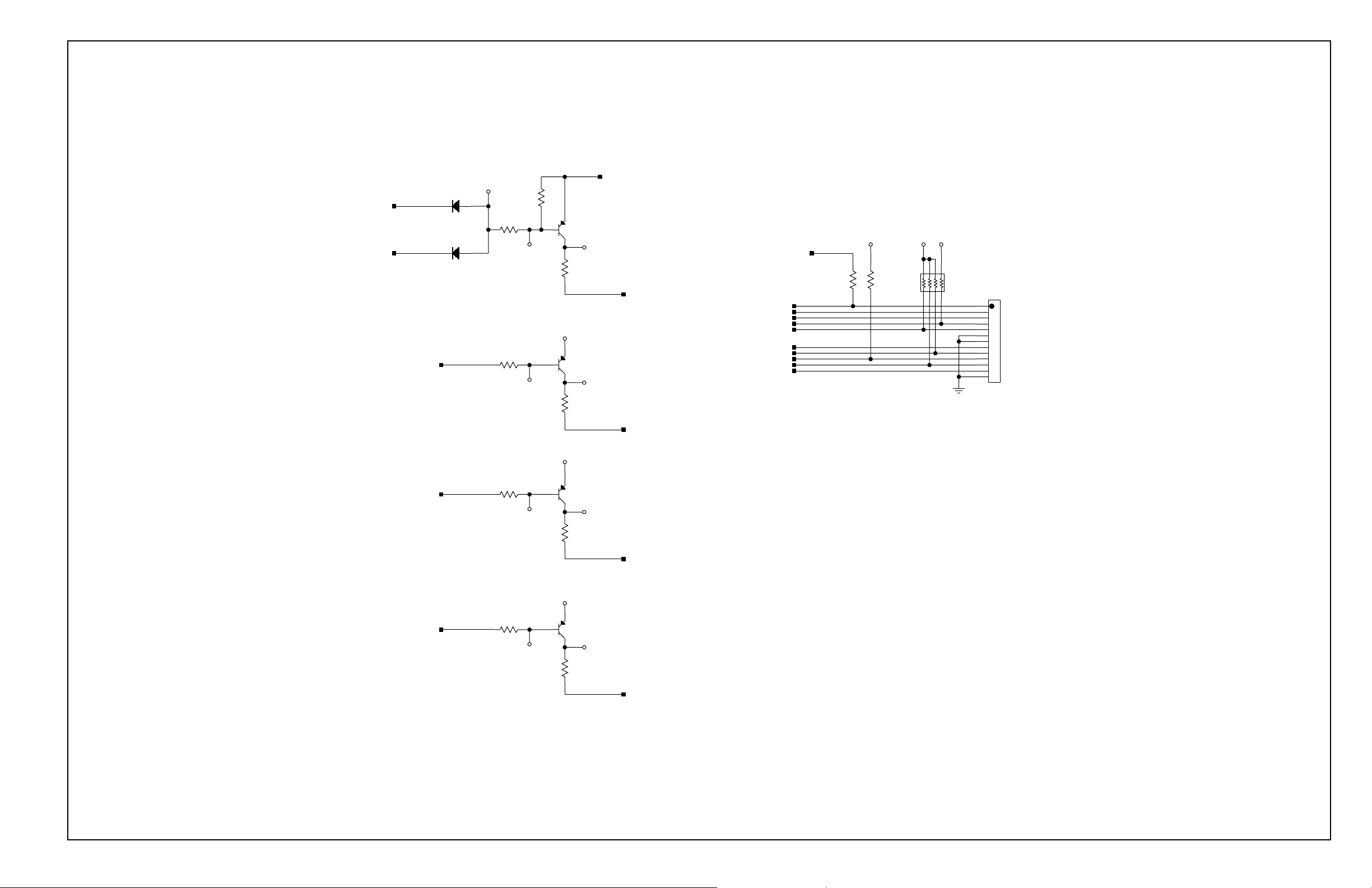
I205
PWRIND-L
ACIND_L
CR19
1N914S
3
CR21
1N914S
31
3
1
1
1
4.75K
R129
10.0K
R94
I206
AC LED DRIVE CIRCUIT
R82
AL_SIL_IND
4.75K
I209
ALARM SILENCE INDICATOR DRIVE CKT
R83
PSRCH_IND
4.75K
I211
1
1
1
1
1
1
VDD
VDD
2
2
3
3
2
2
3
3
2
2
3
3
PICPWR
2N3906S
Q15
I207
R97
249
RPWR_IND
2N3906S
Q12
I208
R103
249
RAL_SIL_IND
2N3906S
Q13
I210
R105
249
VDD
PICPWR
10.0K
R85
PWR_BTN
RPWR_IND
RBATT_IND
BTN_4
BTN_1
RPSRCH_IND
BTN_2
BTN_5
BTN_3
RAL_SIL_IND
R90
10.0K
MEMBRANE PANEL CONNECTOR
876
876
123
123
VDDVREF
5
5
RP4
10K
4
4
J5
1
1
2
2
3
3
4
4
5
5
6
6
7
7
8
8
9
9
10
10
11
11
12
12
13
13
CON_FLEX13
035191
PULSE SEARCH IND DRIVE CKT
R84
BATT_IND
4.75K
I213
BATTERY IND DRIVE CKT
1
1
VDD
2
2
3
3
RPSRCH_IND
2N3906S
Q14
I212
R106
249
RBATT_IND
Figure S-10
Indicator Drive Schematic Diagram (Sheet 8 of 10)
S-25
Page 84

J6
4
3
2
CON_4L_156
To Linear Power Supply
1
MAIN_OUT
BATT_CHECK
BATT
R125
100K
I216
I217
VDD
R119
249K
C114
0.1U
CR26
1 3
1N914S
3
R123
100K
+
568
+
-
-
1331
CR24
1N914S
10.0M
4
R116
U35
LM393S
7
C119
0.1U
R114
127K
R112
20.0K
PICPWR
R140
10.0K
MAIN_OUT
R139
100K
AC_OK
I240
I215
I180
TP46
R135
100K
R115
10.0M
+
-
R138
100K
TP13
CR17
1221
MBRS330T3
VDD
U35
LM393S
+
823
4
-
I241
1
PICPWR
I232
I214
1 2N7002S1
VDD
R134
10.0K
AC_OK-L
R137
100K
ACIND_L
3
3
Q17
2
2
MAIN_DC1
Sh 8
Sh 9
R126
332K
Q16
U33
MIC5200-5
1
IN
GND1
C109
+
1U
35V
SI9953
1
78
2
Q16
I222
SI9953
3
65
4
C113
0.1U
OUT
GND2
31
3
42
42
Requires Heatsink NPB #891196
PICPWR
TP1
C108
+
10U
16V
CR18
1N914S
U36
1
13
IN
TH 25
13 13
LM2940H
OUT
HSG12CS
4
5
VC1206
C111
0.1U
3
CR22
5.6V
1 221
PICPWR
C112
0.1U
VDD
TP38
GND
TP39
VDD
+
C107
470U
16V
TH
R128
4.99K
VDD
8
4
TP47
6
5
U37
LT1009S
I218
V_REF
C106
I223
2N3904S
0.22U
50V
CR23
BATT
R107
200K
CR25
3 11
+
C115
1.0U
20V
I220
BAT54
Critical at approx 5.68V
R108
6.81K
Low at approx 5.85V
R122
150K
R113
10.0M
VDD
+
+
-
-
VDD
+
568
+
-
-
R136
10.0M
U38
LM393S
823
4
4
1
U38
LM393S
7
Normally HIGH, active LOW
VDD
R124
4.99K
Normally HIGH, active LOW
VDD
R118
4.99K
TP42
TP43
CRIT_BATT-L
LOW_BATT-L
12 12
MBRS330T3
Q18
R127
100
LOW to enable
VDD output
3
3
2
2
I219
R120
R121
10.0K
49.9K
PWR_CTRL
HIGH to turn ON
1
1
035191
Figure S-11
Core Power Supply Schematic Diagram (9 of 10)
S-27
Page 85

NELLCOR PURITAN BENNETT
NPB-190 MAIN BOTTOM SIDE
NELLCOR PURITAN BENNETT
NPB-190 MAIN TOP SIDE
FAB 035190 REV A
035192
TOP SIDE BOTTOM SIDE
Figure S-12
Parts Locator Diagram for UIF PCB (10 of 10)
S-29
Page 86

VDD
C3
1000P
TH
GND
TP1
TP2
VDD
CON_7X2R235
VDD
+
C2
47U
10V
TH
J1
2
1
2
1
4
IICDATA
43
6
65
LEDEN
87
8
10
9
10
9
IIC_SCK
1211
1211
1413
1413
C1
0.1U
TH
33.2K
R9
TH
19
19
18
18
12
12
13
13
1
1
9
9
4
4
U1
PWR
ISET
DIN
LOAD
CLOCK
GND1
GND2
MAX7219
DIG0
DIG1
DIG2
DIG3
DIG4
DIG5
DIG6
DIG7
SEGA
SEGB
SEGC
SEGD
SEGE
SEGF
SEGG
SEGDP
DOUT
2
2
DIG1
11
DIG2
11
6
DIG3
6
7
DIG4
7
3
DIG5
3
10
DIG6
10
5
DIG7
5
8
DIG8
8
14
SEGA
14
16
SEGB
16
20
20
SEGC
23
SEGD
23
21
SEGE
21
15
SEGF
15
17
17
SEGG
22
SEGDP
22
24
24
TH
SEGA
SEGB
SEGC
SEGD
SEGE
SEGF
SEGG
SEGDP
DIG1
DS1
10 10
10
A
A
9
9
B
F
8
8
C
5
5
D
4
4
E
E
2
2
F
3
3
G
7
7
DP
1
1
CA1
6
6
CA2
NKR141SC TH
B
G
C
D
DP
10
A
9
9
B
8
8
C
5
5
D
4
4
E
2
2
F
3
3
G
7
7
DIG2
DS2
10 10
10
A
A
9
9
B
F
8
8
C
5
5
D
4
4
E
E
2
2
F
3
3
G
7
7
DP
1
1
CA1
6
6
CA2
NKR141SC TH
B
G
C
D
DP
A
B
C
D
E
F
G
DS3
10
9
9
8
8
5
5
4
4
2
2
3
3
7
7
10 10
10
DIG3
A
A
9
9
B
F
8
8
C
5
5
D
4
4
E
E
2
2
F
3
3
G
7
7
DP
1
1
CA1
6
6
CA2
NKR141SC TH
B
G
C
D
DP
10
A
9
9
B
8
8
C
5
5
D
4
4
E
2
2
F
3
3
G
7
7
DIG4
DS4
10 10
10
A
A
9
9
B
F
8
8
C
5
5
D
4
4
E
E
2
2
F
3
3
G
7
7
DP
1
1
CA1
6
6
CA2
NKR141SC TH
B
G
C
D
DP
10
A
9
9
B
8
8
C
5
5
D
4
4
E
2
2
F
3
3
G
7
7
DS5
10 10
10
A
A
9
9
B
F
8
8
C
5
5
D
4
4
E
E
2
2
F
3
3
G
7
7
DP
1
1
CA1
6
6
CA2
NKR141SC TH
B
G
C
D
DS6
A
B
C
D
E
F
G
DP
CA1
CA2
A
F
E
B
G
C
D
DP
THNKR141SC
10
10
A
9
9
B
8
8
C
5
5
D
4
4
E
2
2
F
3
3
G
7
7
DP
DIG6DIG5
10
9
9
8
8
5
5
4
4
2
2
3
3
7
7
1
1
6
6
PULSE RATESpO2
DS7 TH
DIG8
DIG7
SEGDP
SEGG
SEGF
SEGE
SEGD
SEGC
SEGB
SEGA
11
2
2
3
3
4
4
5
5
6
6
7
7
8
8
9
9
10
10
HDSP-4830
20
20
19
19
18
18
17
17
16
16
15
15
14
14
13
13
12
12
11
11
035195
Figure S-13
Display PCB Schematic Diagram (1 of 2)
S-31
Page 87

NELLCOR PURITAN BENNETT
NPB-190 DISPLAY TOP SIDE
035196
Figure S-14
Parts Locator Diagram for Display PCB (2 of 2)
S-33
Page 88

W2
18GA_BRN
W1
18GA _GRN/YEL
W3
18GA_BLU
Power Entry
MAIN_DC
NEUTRAL
U3
1
1
VIN
3
3
GND
LM35D
LINE
LINE_IN
AC-
C8
0.01U
AC+
C6
0.01U
41
41
BR1
GBU8B
2
2
TH
3
3
C3
220P
250V
TH
7
9
T1
E
29
C1
220P
250V
TH
2
R2
100M
1/4W
DT1
600V TH
E3490A
TH
4
47
NEUT_IN
TH
4700P
250V
R1
390K
1/2W
TH
C2
TH
E
115V
230V
SW1
32112
6
6
45
EPS2PC3
TH
T2
15
1
15
1
13
3
13
3
12
6
12
6
5
10
8
108
OB24-9
TH
FAC+
FAC-
F1
TH2ASB
F2
2ASB TH
ESD Protection
E
Battery Charge
2
2
3
3
R14
10.0K
2N3904
Q3
MPSA56
1
1
Q4
TH
3
3
1
1
VOUT
C4
R22
I5
R21
73.2K
U1
+
578
+
6
-
-
R25
10.0M
LM358
4
I6
VREF
I3
FAN_CTRL
I7
R11
10.0K
848
4
R12
10.0K
U2
LM385S
TP1
2
3
I1
R6
100K
C11
0.1U
10.0K
R20
10.0K
2
2
TH
C10
0.1U
-
+
154K
100P
U1
+
LM358
8
1
4
-
R7
I2
I12
1N914S
CR6
31
R9
1.00K
R8
1.00K
13
1/4W
2
2
R24
49.9
10.0K
TH
I4
R16
HIGH CURRENT VIAS
I10
+
C7
0.1U
10.0K
R3
I9
R17
10.0K
R15
49.9K
1
C5
15000U
35V
TH
3
3
Q6
2N7002S
2
2
I11
R5
1.00K
1/2W
TH
R10
1.50
1/2W
R13
10.0K
I8
CR7
13
13
1N914S
BATT_CHK
MAIN_DC
Q5
MPSA56
3223
R19
Q2
IRF9510
TH
4
Requires Heat Sink
Nellcor # 891196
CR4
MBRS330T3
CHG_OUT
1.00K
CR5
22V
SMCJ22C
2121
TH
CHG_IN
3
3
1
1
2
2
1221
R23
10.0K
1
1
FAN_CTRL
SW2
MTS50B
TH
NC
R4
499
2N3904
BATT_CHK
MAIN_DC
BATT_OUT
THQ1
1331
2
2
CR1
1N4702
15V
2121
TH
Main Board
F3
W7
22GA_WHT
W9
22GA_RED
W6
22GA_ORN
W8
22GA_BLK
GND
TP2
BATT+
TH2ASB
Fan Control
CR2
22V
SMCJ22C
2112
W4
22GA_RED
W5
22GA_BLK
+
Battery +
Battery -
TH
35V
100U
C9
J1
2
1
CON_2L
To Fan
035199
Figure S-15
Power Supply Schematic Diagram (1 of 2)
S-35
Page 89

"+"
"N"
"L"
"GND"
NELLCOR PURITAN BENNETT
NPB-190 LPS TOP SIDE
"-"
035200
Figure S-16
Parts Locator Diagram for Power Supply PCB (2 of 2)
S-37
 Loading...