

Page 1
Safety
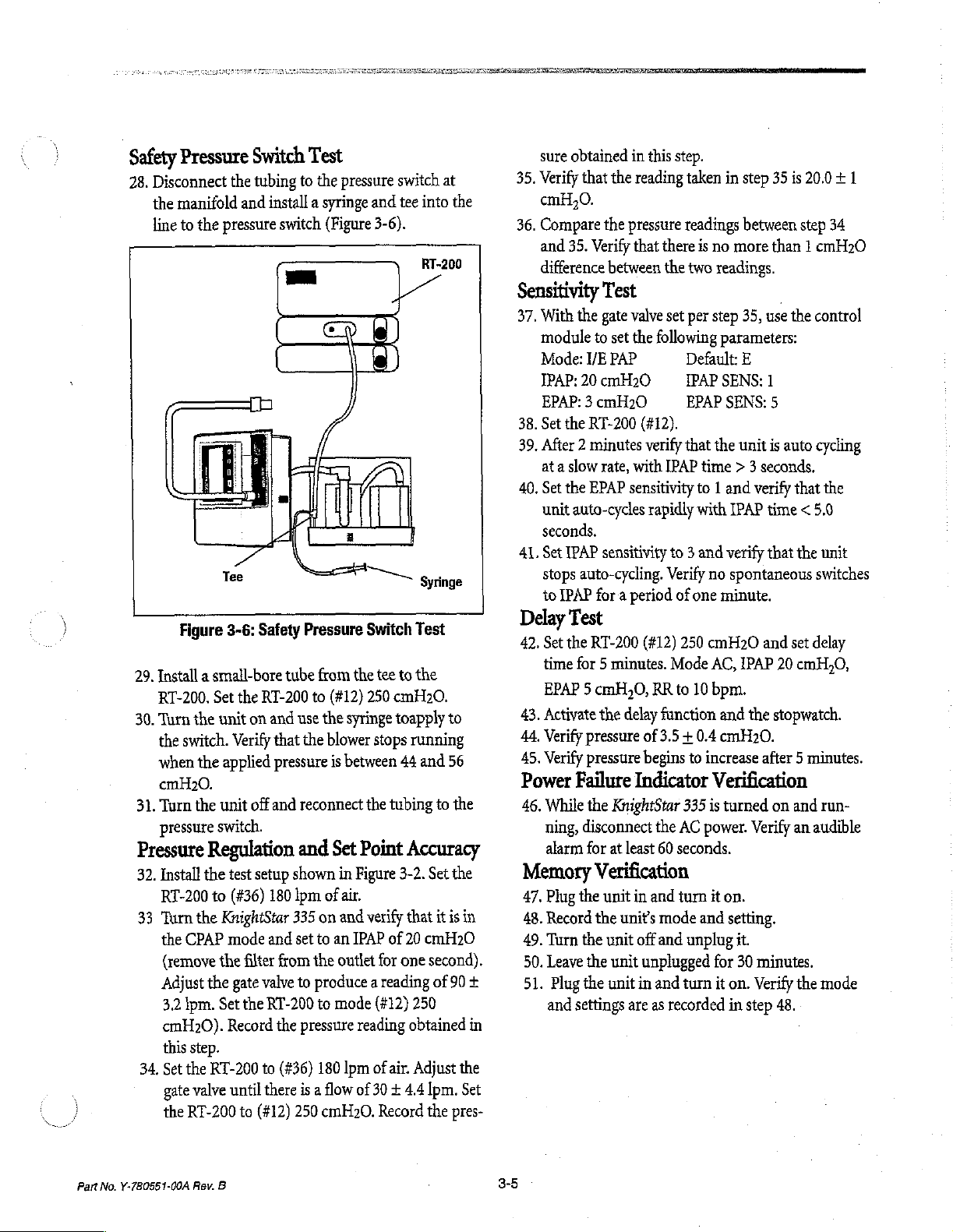
28.
Pressure
Disconnect
the
manifold
line
to
the
pressure
the
29.
Install a small-bore
RT-200.
30.
Turn
the
when
cmH20.
31.
Turn
pressure
Pressure
32.
Install
RT-200
33
Turn
the
(remove
Adjust
3.2
cmH20).
this
34,
Set
gate
the
Tee
Figure
3-6:
Set
the
unit
switch.
the
applied
the
unit
switch.
Verify
Regulation
the
test
to
(#36)
the
KnightStar
CPAP
mode
the
the
gate
Ipm.
Set
Record
step.
the
RT-200
valve
until
RT-200
Switch
tubing
and
Safety
the
on
off
Test
to
the
install a syringe
switch
Pressure
tube
from
RT-200
to
and
use the
that
the
pressure
and
reconnect
and
setup
shown
180
lpm
335
on
and
set
to
filter
from
the
valve
to
produce a reading
the
to
there
to
(#12)
RT-200
to
the
pressure
(#36)
is a flow
250
180
pressure
and
(Figure
blower
of
Switch
the
(#12)
250
syringe
is
between
the
Set
Point
in
Figure
air.
and
verify
an
IPAP
outlet
mode
reading
lpm
3-6).
stops
(#12)
of
of 30 + 4.4
cmH20.
switch
tee
into
RT-200
Syringe
Test
tee
to
the
cmH20.
toapply
running
44
and
tubing
Accuracy
3-2.
Set the
that
of
20
cmH20
for
one
second).
250
obtained
air.
Adjust
Ipm.
Record
the
at
the
to
56
to
the
it
is
of
90
pres-
in
+
in
the
Set
sure
35,
Verify
cmH,0.
36.
Compare
and
difference
Sensitivity
37,
With
module
Mode:
IPAP:
EPAP: 3 cmH20
38.
Set
39.
After 2 minutes
at a slow
40.
Set
unit
seconds.
41. Set
stops
to
IPAP
Delay
42,
Set
time
EPAP 5 cmH,0,
43,
Activate
44.
Verify
45.
Verify
Power
46.
While
ning,
alarm
Memory
47.
Plug
48.
Record
49.
Turn
50.
Leave
51.
Plug
and
obtained
that
35.
in
the
reading
the
pressure
Verify
that
this
there
between
Test
the gate
20
the
the
auto-cycles
IPAP
auto-cycling.
valve
to
set
the
following
I/E
PAP
cmH20
RT-200
EPAP
(#12).
verify
rate,
with
sensitivity
rapidly
sensitivity
for a period
Test
the
RT-200
for 5 minutes.
(#12)
RR
the
delay
function
pressure
pressure
Failure
the
disconnect
for
of
3.5 + 0.4
begins
Indicator
KnightStar
the
at
least
60
Verification
the
unit
in
and
the
units
mode
the
unit
off
and
the
unit
unplugged
the
unit
in
and
settings
are
as
step.
taken
in
readings
is
no
the
two
readings.
set
per
step
parameters:
Default:
IPAP
SENS:
EPAP
SENS:
that
the
IPAP
time > 3
to 1 and
with
IPAP
to 3 and
Verify
of
Mode
to
one
250
10
verify
no
spontaneous
minute.
cmH20
AC,
bpm.
and
cmH20.
to
increase
Verification
335
is
turned
AC
power.
seconds.
turn
it
on.
and
setting.
unplug
for
turn
it
on.
recorded
in
step
35
is
20.0 + 1
between
more
35,
E
unit
IPAP
the
Verify
step
than 1 cmH20
use
the
1
5
is
auto cycling
seconds.
verify
that
time
< 5,0
that
the
and
set
delay
20
cmH,0,
stopwatch.
after 5 minutes.
on
and
an
audible
it.
30
minutes.
Verify
the
step
48.
34
control
the
unit
switches
run-
mode
Part
No.
Y-780551-00A
Rev.
B
3-5
Page 2
Assembled
52.
Disconnect
equipment
base
through
53.
Connect
using
54.
Connect
MAINS
55.
Turn
powered
and
56.
Verify
panel
57.
Toggle
control
58,
Enable
pushing
PLAY
59.
Install
NASAL
the
with
+0.5
60.
Repeat
TIDAL
lowing
mode:
61.
Simultaneously
ARROW
log
62.
Simultaneously
ARROW
mal
63.
Connect a bacteria
tube,
outlet
64.
Turn
the
and
65.
Set
Adjust
+
66.
Set
pressure
Tests
unit
and
unit
per
ae.
the
the
6-foot
the
ON
the
unit
up,
the
three
the
green
is
illuminated.
through
module
the
calibration
the
key
until a “C”
the
analog
PRESSURE
control
the
fluke
to
0.0
step
VOLUME
outputs
Output
key
outputs
key
operation.
pressure
of
the
the
unit
mode
to
remove
the
RT-200
the
4.4
lpm.
the
RT
indicated
from
AC
the
bacteria
section
control
unit
light
and
indicator
DOWN
4,
procedure
module
cable.
to
an
AC
is
illuminated.
on.
Verify
the
control
LEDs
POWER
all
selectors
to
verify
outputs
ARROW
is
displayed.
output
analog
module.
£0.1
60
at
Verify
87
in
the
min/max
VDC.
for
EST
PATIENT
analog
with
the
of
0.5
to
press
the
until a “0”
0.0
+ 0.1
press
the
to
return
the
filter,
tee
gate
valve,
KnighiStar
on
and
use
CPAP
with a pressure
filter
from
to
the
180
gate
valve
to
to
(#12)
250
on
RT-200
source,
that
ON
that
cable
outputs.
fluke
-0.5
DISPLAY
is
Remove
filter.
Assemble
|,
steps
to
the
KnighiStar
source
and
verify
when
the
unit
panel
DELAY
momentarily
LED
on
the
and
fields
on
they
are
operational.
by
simultaneously
key
and
the
into the
output
the
following
on
EST
the
mode:
FLOW
Verify
87
in
the
£0.1
VDC.
and
displayed.
Verify
all
the
o
is
LED
light.
front
the
DIS-
back
outputs
Output
and
the
min/max
DOWN
volts.
DISPLAY
analog
the
335
the
outlet
Ipm
produce a reading
cmH,0.
and
outputs
6-foot
and
RT-200
as
shown
control
of
for
one
air
range
Verify
is
20
UP
to
smooth
to
in
figure
module
20
cmH20
second.
(#36).
of
that
+0.1
cmH,0.
test
335
the
first
of
of
EST
fol-
all
ana-
nor-
bore
the
3-2.
to
set
30
the
67.
Remove
unit.
68.
Verify
ed
69.
Set
DELAY
nated.
control
Current
Test
70.
Connect
rear
that
Disconnect
source.
71.
Connect
tester.
O.lohms
and
72.
Turn
rent
both
Remote
73.
Set
and
74,
Connect
power
75.
From
KnightStar
using
76.
Remove
the
the
77,
From
remote
KnightStar
be
control
78.
Move
module
position.
79.
Return
80.
Disconnect
the
circuit
assembly
that
the
LEAK
indication
within
60
to
80
seconds.
the
delay
interval
button
Turn
the
module
to 5 minutes.
and
verify
KnightStar
from
the
Leakage/Ground
the
AC
power
panel
receptacle
the
rear
panel
the
the
AC
Verify
that
between
the
KnightStar
on
the
KnightStar
leakage
normal
is
and
Control
the
data
rate
the
IR
module
the
IR
switch
approximately
335
the
remote
the
IR
data
rate
switches
remote
activated
control
approximately
control
335.
by
buttons.
the
data
and
the
Repeat
the
switches
unit
and
AC
KnightStar
power
ground
the
power
335’s
less
than
reverse
Test
switches
in
opposite
module
of
the
base
15
can
not
control.
module
to
15
toward
Verify
pressing
rate
switches,
remote
step
75.
to
from
from
the
LED
DELAY
base
cord
to
indicator
cord
line
metal
335
100
LED
335
off
and
unit.
Line
Resistance
to
the
KnightStar
an
AC
source.
is
illuminated.
335
from
to
the
resistance
cord
grounding
chassis.
and
verify
micro
amperes
polarity.
(If
Remote
in
the
remote
positions.
to
the
base
unit
in
the
feet
away,
verify
be
activated
from
the
base
on
both
the
IR
the
same
data
feet
away,
point
the
IR
Module
that
the
KnightStar
the
appropriate
on
both
control,
their
AC
to
original
source.
outlet
of
the
is
illuminat-
Press
the
is
illumi-
disconnect
335
Verify
the
AC
electrical
is
less
that
the
safety
than
pin
cur-
for
is
Used)
control
unit.
Place
the
ON
position.
that
the
or
deactivated
unit
and
set
module
rate
and
position.
the
on
the
335
can
remote
the
IR
the
opposite
settings.
Part
No.
Y-780551-00A
Rev.
B
Page 3
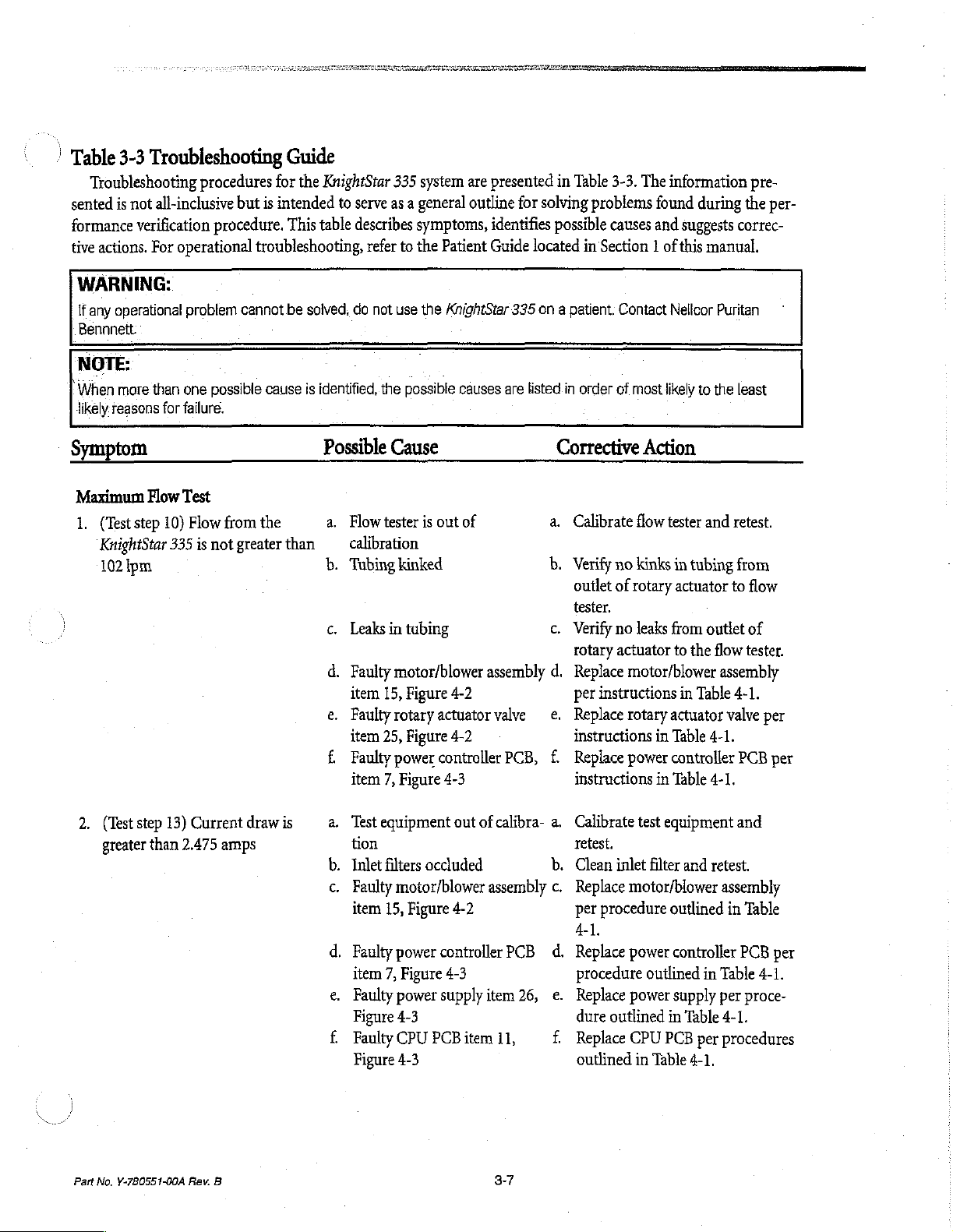
Table
3-3
Troubleshooting
Troubleshooting
sented
is
not
all-inclusive
formance
tive
verification
actions.
For
operational
WARNING:
If
any
operational
Bennnett.
NOTE:
|
When
more
than
one
likely
reasons
Symptom
for
failure.
procedures
but
procedure.
troubleshooting,
problem
cannot
possible
Guide
for
the
is
intended
This
be
solved,
cause
is
KnightStar
to
table
identified, the
Possible
335
serve
as a general
describes
refer
to
do
not
use
possible
Cause
system
symptoms,
the
are
outline
Patient
the
KnightStar
causes
presented
identifies
Guide
are
in
for
solving
possible
located
335
on a patient:
listed.in
Corrective
Table
3-3.
problems
causes
in
Section 1 of
Contact
order
of
The
information
found
and
suggests
this
Nellcor
most
likely
Action
pre-
during
the
correc-
manual.
Puritan
to
the
least
per-
Maximum
1.
(Test
step
KnightStar
102
pm
2.
(Test
step
greater
Flow
10)
335
13)
than
Test
Flow from
is
not
greater
Current
2.475
amps
the
draw
than
is
a.
Flow
tester
calibration
b.
Tubing
c.
Leaks
in
d.
Faulty
item
15,
e.
Faulty
item
25,
Е
Faulty
item
7,
a.
Test
equipment
tion
b.
Inlet
filters
c.
Faulty
item
15,
4.
Faulty
item
7,
e.
Faulty
Figure
ЕЁ
Faulty
Figure
is
out
of
kinked
tubing
motor/blower
Figure
rotary
actuator
Figure
power
controller
Figure
4-2
4-2
4-3
out
assembly
valve
of
calibra-
occluded
motor/blower
Figure
power
controller
Figure
power
supply
4-3
CPU
PCB
4-3
4-2
4-3
item
assembly
item
11,
PCB,
PCB
26,
a.
Calibrate
b.
Verify
no
outlet
of
tester.
с.
Verify
no
rotary
actuator
d.
Replace
per
instructions
—e.
Replace
instructions
£
Replace
instructions
a.
Calibrate
retest.
b.
Clean
inlet
c.
Replace
per
procedure
4-1.
ἆ,
Replace
procedure
e.
Replace
dure
outlined
f.
Replace
outlined
flow
tester
and
retest.
kinks
in
tubing
rotary
actuator
leaks
from
to
motor/blower
in
rotary
actuator
in
Table
power
controller
in
Table
test
equipment
filter
and
motor/blower
outlined
power
controller
outlined
power
supply
in
CPU
PCB
in
Table
outlet
the
flow
assembly
Table
valve
4-1.
4-1.
retest.
assembly
in
in
Table
per
Table
4-1.
per
procedures
4-1.
to
4-1.
from
flow
of
tester.
per
PCB
per
and
Table
PCB
per
4-1.
proce-
Part No.
Y-780551-00A
Rev.
B
3-7
Page 4
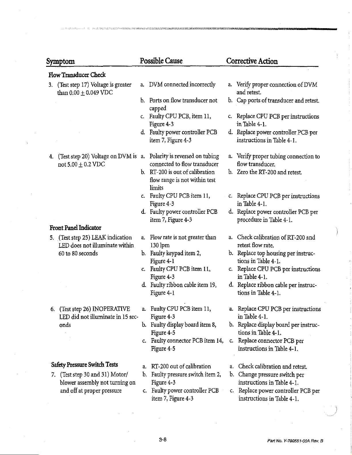
Symptom
Flow
Transducer
3.
(Test
step
than
0.00 + 0.049
4,
(Test
step 20)
not
5.00 + 0.2
Front
Panel
5,
(Test
step
LED
does
60
to
80
Check
17)
Voltage
VDC
Voltageon
VDC
Indicator
25)
LEAK
indication
not
illuminate
seconds
is
greater
DVMis
within
Possible
a.
b.
Cause
DVMconnectedincorrectly
Ports on
flow
transducer
capped
c.
Faulty
CPU
PCB,
item
Figure
4-3
d.
Faulty
power
controller
item
7,
Figure
4-3
a.
Polarity
connected
b.
RT-200
flow
limits
c.
Faulty
Figure
4.
Faulty
item
a.
Flow
130
b.
Faulty
Figure
c.
Faulty
Figure
d.
Faulty
Figure
is
is
out
range
CPU
4-3
power
7,
Figure
rate
is
jpm
keypad
4-1
CPU
4-3
ribbon
4-1
reversed
to
is
not
ontubing
flow
transducer
of
calibration
not
within
PCB
item
controller
4-3
greater
item
2,
PCB
item
cable
item
not
11,
PCB
test
11,
PCB
than
11,
19,
Corrective
a.
Verify
and
—_b.
Cap
с.
Replace
in
d.
Replace
instructions
a.
Verify
flow
b.
Zero
c.
Replace
in
d.
Replace
procedure
a.
Check
retest
b.
Replace
tions
c.
Replace
in
d.
Replace
tions
Action
proper
retest.
ports
of
CPU
Table
4-1,
power
proper
transducer.
the
RT-200
CPU
Table
4-1.
power
in
calibration
flow
rate.
top
in
Table
CPU
Table
4-1.
ribbon
in
Table
connection
transducer
PCB
controller
in
Table
tubing
and
PCB
controller
Table
housing
4-1.
PCB
cable
and
per
instructions
4-1.
connection
retest.
per
instructions
4-1.
of
RT-200
per
per
instructions
per
4-1.
of
DVM
retest.
PCB
per
to
PCB
per
and
instruc-
instruc-
6.
(Test
LED
onds
Safety
Pressure
7.
(Test step
blower
and
step
26)
did
not
Switch
30
assembly
off
at
proper
INOPERATIVE
illuminate
and
in
Tests
31)
Motor/
not
turning
pressure
15
a.
sec-
b.
on
Faulty
Figure
Faulty
Figure
с.
Faulty
Figure
a.
RT-200
b.
Faulty
Figure
с.
Faulty
item
CPU
4-3
display
4-5
connector
4-5
out
pressure
4-3
power
7,
Figure
3-8
PCB
item
11,
board
item
PCB
item
of
calibration
switch
item
controller
4-3
8,
PCB
14,
2,
a.
Replace
in
b.
Replace
tions
c.
Replace
instructions
a.
Check
Ob.
Change
CPU
Table
4-1.
display
in
Table
connector
calibration
pressure
instructions
c.
Replace
instructions
power
PCB
per
board
4-1.
PCB
in
Table
4-1.
and
switch
in
Table
4-1.
controller
in
Table
4-1.
Part
No.
Y-780551-00A
instructions
per
instruc-
per
retest.
per
PCB
per
Rev.
B
Page 5
|
2
Symptom
Pressure
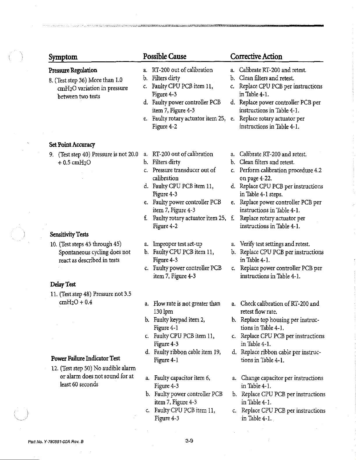
8.
Set
9,
Sensitivity
10,
Delay
11.
Power
12.
Regulation
(Test
step 36)
cmH20
between
Point
(Test
+
variation
Accuracy
step
0.5
cmH20
two
40)
Tests
(Test
steps
Spontaneous
react
as
described
Test
(Test
step 48)
cmH20 + 0.4
Failure
(Test
step 50)
or
alarm
does
least
60
seconds
More
than
1.0
in
pressure
tests
Pressure
43
through
cycling
Pressure
Indicator
No
not
is
not
45)
does
in
tests
not
Test
audible
sound
for
20.0
not
3.5
alarm
at
Possible
a.
RT-200
b.
Filters
с.
Faulty
Figure
d.
Faulty
item
e.
Faulty
Figure
a.
RT-200
b.
Filters
c.
Pressure
calibration
d.
Faulty
Figure
e.
Faulty
item
f.
Faultyrotary
Figure
a.
Improper
b.
Faulty
Figure
с.
Faulty
item
a.
Flowrateis
130
b.
Faulty
Figure
c.
Faulty
Figure
d.
Faulty
Figure
a.
Faulty
Figure
b.
Faulty
item
с.
Faulty
」
Figure
Cause
out
of
dirty
CPU
PCB
4-3
power
controller
7,
Figure
rotary
actuator
4-2
out
of
dirty
transducer
CPU
PCB
4-3
power
controller
7,
Figure
actuator
4-2
test
CPU
PCB
4-3
power
controller
7,
Figure
not
Ipm
keypad
4-1
CPU
PCB
4-3
ribbon
4-1
capacitor
4-3
power
7,
Figure
CPU
PCB
4-3
calibration
item
11,
PCB
4-3
item
25,
calibration
out
of
item
11,
PCB
4-3
item
25,
set-up
item
11,
PCB
4-3
greater
item
cable
controller
4-3
than
2,
item
11,
item
item
6, a.
PCB
item
11,
19,
Corrective
a.
Calibrate
b.
Clean
c.
Replace
in
Od.
Replace
instructions
e.
Replace
instructions
a.
Calibrate
b.
Clean
c.
Perform
on
d.
Replace
in
e.
Replace
instructions
f.
Replace
instructions
a.
Verify
b.
Replace
in
c.
Replace
instructions
a.
Check
retest
b.
Replace
tions
c.
Replace
in
d.
Replace
tions
Change
in
b.
Replace
in
c.
Replace
in
Action
RT-200
filters
and
CPU
Table
4-1.
power
in
rotary
in
RT-200
filters
and
calibration
page
4-22.
CPU
Table
4-1
steps.
power
rotary
test
settings
CPU
Table
4-1.
power
calibration
flow
rate,
top
housing
in
Table
CPU
Table
4-1.
ribbon
in
Table
capacitor
Table
4-1.
CPU
Table
4-1.
CPU
Table
4-1.
and
retest.
retest.
PCB
per
instructions
controller
Table
4-1.
actuator
Table
per
4-1.
and
retest.
retest.
procedure
PCB
per
instructions
controller
in
Table
4-1.
actuator
in
Table
PCB
controller
in
Table
per
4-1.
and
retest.
per
instructions
4-1.
of
RT-200
per
4-1.
PCB
per
instructions
cable
per
4-1.
per
instructions
PCR
per
instructions
PCB
per
instructions
PCB
per
4.2
PCB
per
PCB
per
and
instruc-
instruc-
Part No.
Y-780551-00A
Rev.
B
3-9
Page 6
Symptom
Possible
Cause
Corrective
Action
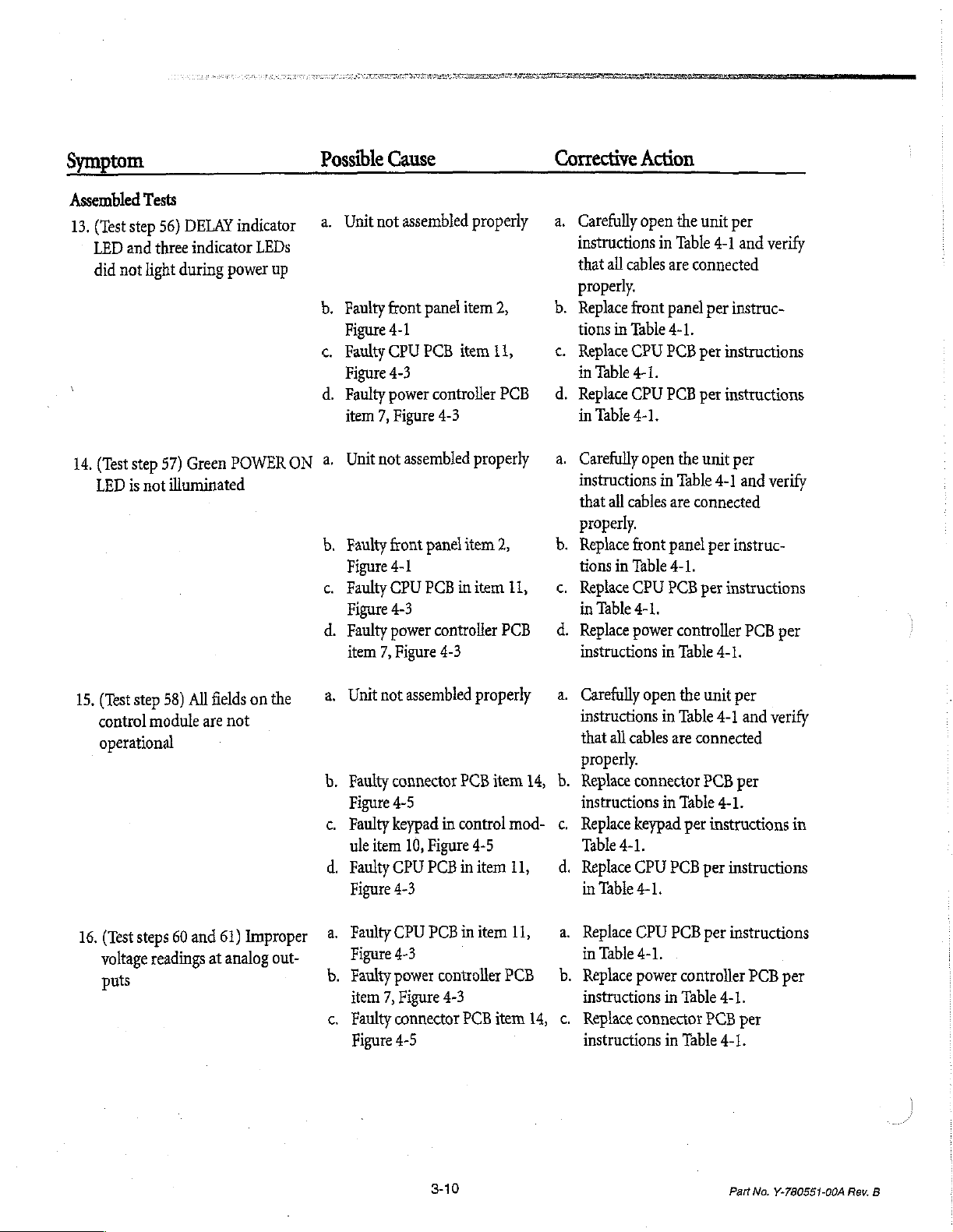
Assembled
13.
(Test
step
LED
and
did
not
14,
(Test
step
LED
is
Tests
56)
DELAY
three
indicator
light
during
57)
Green
not
illuminated
indicator
LEDs
power
up
POWER
ON
a.
b.
c.
d.
a.
b.
с.
d.
Unit
Faulty
Figure
Faulty
Figure
Faulty
item
Unit
Faulty
Faulty
not
front
4-1
CPU
4-3
power
7,
Figure
not
front
Figure
4-1
CPU
Figure
4-3
Faulty
power
item
7,
Figure
assembled
panel
PCB
assembled
PCBinitemil,
properly
item
item
controller
4-3
properly
panel
item
controller
4-3
2,
11,
PCB
2,
РСВ
a.
Carefully
instructions
that
all
cables
properly.
b.
Replace
tions
<.
Replace
in
4.
Replace
in
κ.
Carefully
instructions
that
properly.
b.
Replace
tions
<
Replace
in
4.
Replace
instructions
front
in
Table
CPU
Table
4-1.
CPU
Table
4-1.
all
cables
front
in
Table
CPU
Table
power
4-1.
open
the
in
Table
are
panel
4-1.
PCB
PCB
open
the
in
Table
are
panel
4-1.
PCB
controller
in
Table
unit
per
4-1
and
verify
connected
per
instruc-
per
instructions
per
instructions
unit
per
4-1
and
verify
connected
per
instruc-
per
instructions
PCB
4-1.
per
15,
(Test
step
control
module
operational
16,
(Test
steps
voltage
readings
puts
58) All
are
60
and
fields
not
61)
Improper
at
analog
on
the
out-
a.
Unit
b.
Faulty
Figure
c,
Faulty
ule
4.
Faulty
Figure
a.
Fauliy
Figure
b.
Faulty
item
c.
Faulty
Figure
not
assembled
connector
4-5
keypad
item
10,
Figure
properly
PCB
in
control
4-5
CPUPCBinitem
4-3
CPU
PCBinitemli,
4-3
power
controller
7,
Figure
4-3
connector
4-5
PCB
item
14,
mod-
11,
PCB
item
14,
a.
Carefully
instructions
that
all
cables
properly.
=
Replace
instructions
c.
Replace
Table
4.
Replace
in
a.
Replace
in
b.
Replace
instructions
с.
Replace
instructions
keypad
4-1.
Table
Table
open
the
unit
in
Table
are
connected
connector
CPU
4-1.
CPU
4-1.
power
connector
PCB
in
Table
per
instructions
PCB
per
PCB
per
controller
in
Table
PCB
in
Table
per
4-1
and
verify
per
4-1.
in
instructions
instructions
PCB
per
4-1.
per
4-1.
3-10
Part
No.
Y-780551-00A
Rev.
B
Page 7
neo
`
Symptom
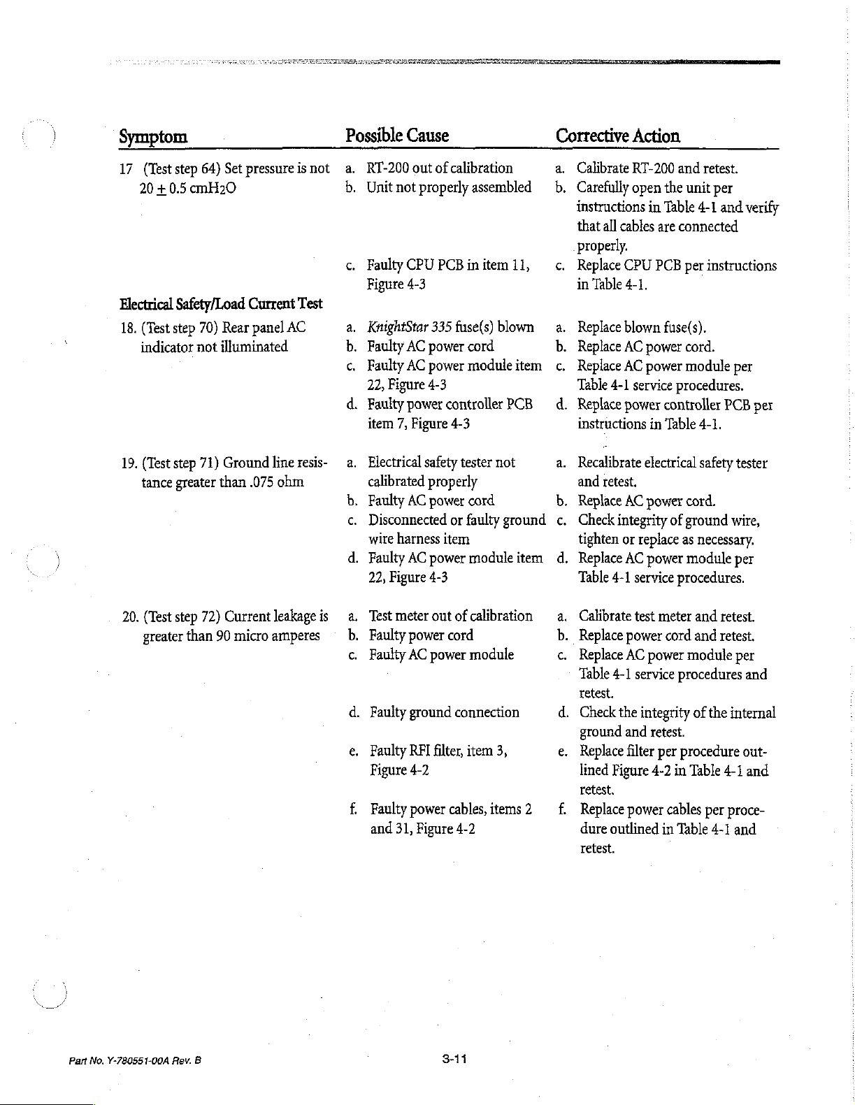
17
(Test
step
20 + 0.5
Electrical
18.
(Test
indicator
19.
(Test
tance
cmH20
Safety/Load
step
70)
not
step
71)
greater
64)
Set
pressure
Current
Rear
panel
illuminated
Ground
than
.075
AC
line
ohm
isnot
Test
resis-
Possible
а.
s
с.
a.
b.
с.
d.
a.
Cause
RT-200
Unit
Faulty
Figure
KnightStar
Faulty
Faulty
22,
Faulty
item
Electrical
out
not
properly
CPU
4-3
AC
AC
Figure
power
7,
Figure
calibrated
b.
Faulty
AC
с.
Disconnected
wire
harness
d.
Faulty
AC
22,
Figure
of
calibration
assembled o b.
PCB
initem
335
fuse(s)
power
cord
power
module
4-3
controller
4-3
safety
tester
properly
power
cord
or
faulty
item
power
module
4-3
11,
blown
item
PCB
not
ground
item
Corrective
a.
Calibrate
Carefully
instructions
that
all
cables
Action
RT-200
open
in
properly.
с.
Replace
in
a.
Replace
b.
Replace
с.
Replace
Table
d.
Replace
instructions
a.
Recalibrate
and
b.
Replace
c.
Check
tighten
d.
Replace
Table
CPU
Table
4-1.
blown
AC
AC
4-1
service
power
retest.
AC power
integrity
or
replace
AC power
4-1
service
power
power
in
electrical
and
retest.
the
unit
per
Table
4-1
and
are
connected
PCB
per
instructions
|
fuse(s).
cord.
module
procedures.
controller
Table
of
procedures.
PCB
4-1.
safety
cord.
ground
as
necessary.
module
verify
per
per
tester
wire,
per
20.
(Test
greater
step
72)
than
Current
90
micro
leakage
is a.
amperes
Test
b.
Faulty
c.
Faulty
d.
Faulty
e.
Faulty
Figure
f.
Faulty
and
meter
power
AC
power
ground
RFI
4-2
power
31,
Figure
out
of
calibration
cord
module
connection
filter,
item
cables,
4-2
a.
Calibrate
b.
Replace
с.
Replace
Table
retest.
d.
Check
ground
3,
e.
Replace
lined
retest.
items 2 (Of
Replace
dure
retest.
test
meter
power
cord
AC
power
4-1
service
the
integrity
and
retest.
filter
per
Figure
4-2
power
cables
outlined
in
and
retest.
and
retest.
module
procedures
of
procedure
in
Table
Table
per
the
internal
4-1
per
proce-
4-1
and
out-
and
and
Part
No.
Y-780551-00A
Rev.
B
3-11
Page 8

3-12
(blank)
Part
No.
Y-780551-00A
Rev.
B
Page 9
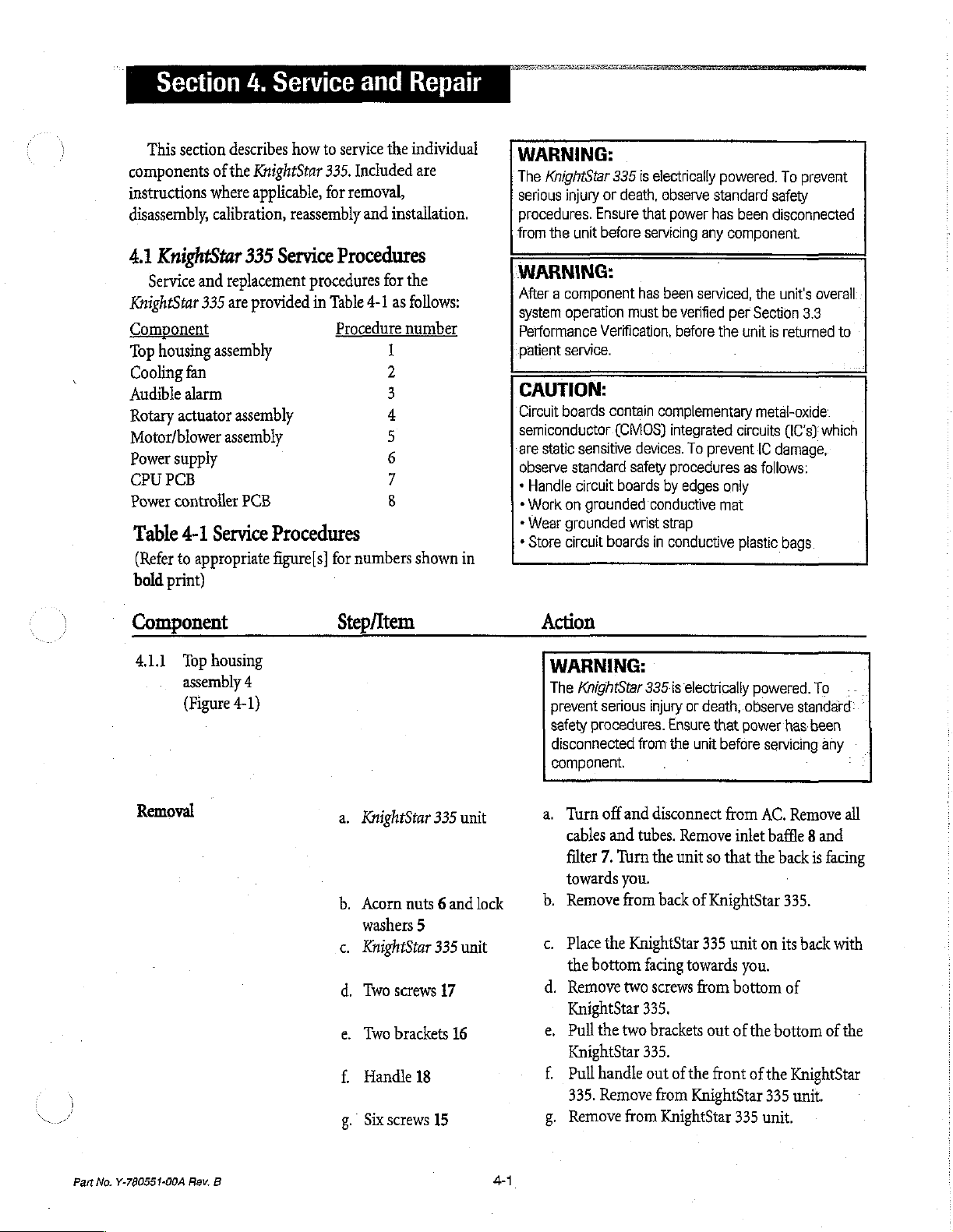
Section
4.
Service
and
Repair
[a
This
section
components
instructions
disassembly,
4.1
KnightStar
Service
KnightStar
Component
Top
housing
Cooling
Audible
Rotary
Motor/blower
Power
supply
CPU
PCB
Power
controller
Table
(Refer
bold
print)
actuator
4-1
to
describes
of
the
where
calibration,
and
replacement
335
are
assembly
fan
alarm
assembly
assembly
Service
appropriate
how
to
KnightStar
applicable,
335.
for
reassembly
335
Service
procedures
provided
PCB
in
Procedures
figure[s]
service
the
individual
Included
are
removal,
and
installation.
Procedures
for
the
Table
4-1
as
follows:
Procedure
for
numbers
number
1
NN
a
U qa
03d
shown
in
WARNING:
The
KnightStar
serious
procedures.
from
WARNING:
After a component
injury
the
system
operation
Performance
patient
service.
335
or
death,
Ensure
unit
before
Verification,
CAUTION:
Circuit
boards
semiconductor.
are
static
observe
*
Handle
*
Work
*
Wear
*
Store
contain
(CMOS)
sensitive
standard
circuit
boards
on
grounded
grounded
circuit
boards
ts
electrically
observe
that
power
servicing
has
been
must
be
verified
before
complementary
integrated
devices.
safety
wrist
To
procedures
by
edges
conductive
strap
in
conductive
powered.
standard
has
been
any
component.
serviced,
per
Section
the
unit
circuits
prevent
as
only
mat
plastic
To
prevent
safety
disconnected
the
unit's
overall
3.3
is
returned
metal-oxide
(IC's}
which
IC
damage,
follows:
bags
to
Component
4.1.1
Top
assembly
(Figure
Removal
housing
4
4-1)
Step/Item
a.
KnightStar
b.
Acorn
nuts 6 and
washers
с.
KnightStar
d.
Two
e.
Two
f.
Handle
g.
Six
5
screws
brackets
18
screws
335
335
17
16
15
unit
lock
unit
Action
WARNING:
The
KnightStar
prevent
safety
disconnected
component.
a.
>
c.
d.
e.
f.
g.
serious
procedures.
Turn
off
cables
and
filter
7.
Turn
towards
Remove
Place
the
the
bottom
Remove
KnightStar
Pullthe
KnightStar
Pull
handle
335.
Remove
Remove
335s
electrically
injury
or
Ensure
from
the
unit
and
disconnect
tubes.
Remove
the
unit
you.
from
back
of
KnightStar
facing
towards
two
screws
335.
two
brackets
335.
out
of
the
from
KnightStar
from
KnightStar
powered.
death,
observe
that
power
before
servicing any
from
AC.
inlet
so
that
the
KnightStar
335
unit
on
you.
from
bottom
cut
ofthe
front
of
the
335
335
unit.
To
standard
has-been
Remove
baffle 8 and
back
is
facing
335.
its
back
with
of
bottom
of
the
KnightStar
unit.
all
Part
No.
Y-780551-00A
Rev.
B
41
Page 10

Component
Installation
Step/Item
h.
KnightStar
i.
KnightStar
Wire
.
Flex
(Figure
KnightStar
.
Wire
.
Top
.
Top
.
Wire
.
Top
.
KnightStar
.
Flex
.
Wire
.
KnightStar
335
335
harness
tubing6
4-2)
harness
housing
housing
harness
housing
tube 6 (Figure
harness
unit
unit
19
335
unit
22
assembly
assembly
22
assembly
335
unit
19
335
unit
4-2)
Action
h.
Place
unit
the sides
housing
the
facing
assembly
front
CAUTION:
Forcing
at
or
i,
}.
k.
1.
m.
n.
o.
p.
q.
т.
s.
t.
u.
the
top
this
time.could
tubing.
Carefully
side
with
Reach
up
disconnect
keypad
Reach
disconnect
outlet
Place
of
housing
forward.
Disconnect
Figure
the
the
Slide
top
the
back
2.
up
3.
sides
assembly
4-3.
completely
unit.
Slide
top
KnightStar
Connect
CPU
PCB
Slide
the
KnightStar
access
to
Carefully
side
with
Reach
up
connect
Reach
up
harness
Place
position.
to
the
back
on
its
bottom
towards
about
of
the
machine.
housing
turn
the
bottom
into the
wire
into the
the
unit
facing
wire
housing
of
the
separated
housing
335
wire
(refer
top
335
connections
turn
the
inside
flex
tube 6 to
inside
keypad
KnightStar
assembly:too
cause
damage
the
KnightStar
facing
top
housing
harness
top
housing
flex
tube
in
an
upright
towards
another
harness
assembly
KnightStar
from
assembly
unit.
harness
housing
bottom
22
to
Figure
assembly
unit
leaving
inside
the
KnightStar
facing
of
the
machine
of
the
2.
335
feet
with
you.
Slide
the
two
inches
towards
far
forward
to
internal
335
unit
towards
you.
assembly
19
from
the
front
assembly
from
the
machine
position
you.
two
22
from
forward
335
the
partially
to
connector
4-4).
enough
of
towards
KnightStar
with
Slide
to
three
PCB
away
unit
until
KnightStar
onto
onto
the
room
the
unit.
335
unit
you.
335
outlet
unit
and
connect
unit
in
the
upright
one
of
top
cables
onto
its
and
and
one
the top
inches
11
on
from
it
is
335
J2
on
for
on
its
unit
and
3.
wire
4-2
Part
No.
Y-780551-00A
Rev.
B
Page 11

Component
4.1.2.
Removal
Cooling
(Figure
fan
4-3)
16
Step/Item
v.
Top
assembly
w.
Lock
washers
x.
KnightStar
y.
Six
screws
z.
Handle
aa.
Two
ab.
Two
ac.
KnightStar
ad.
Acorn
ae.
Filter 7 and
18
brackets
screws
nuts
4
5
335
unit
15
16
17
335
unit
6
inlet
baffle
8
Action
v.
Slide
unit.
NOTE:
It
may
be
the
top
housing
835
to
aid
the
KnightStar
w.
Place
nuts 6 nuts
the
back
this
time.
x.
Place
with
y.
Insert
and
tighten.
z.
Install
front
aa.
Orient
through
KnightStar
ab.
Insert
tighten.
ac.
Place
position.
ad.
Tighten
ae.
Reinstall
of
the
top
assembly
necessary
in
the
plate.
the
the
bottom
the
the
of
the
the
the
two
the
the
KnightStar
to
and
the
alignment
335.
lock
washers
on
the
Do
KnightStar
facing
six
screws
handle
top
housing
through
brackets
slots
in
335
unit.
screws
through
KnightStar
acorn
the
filter
335
onto
the
KnightStar
leave a small
back
of
the
of
posts 1 with
and
acorn
studs
protruding
not
tighten
335
unit
on
towards
through
the
the
assembly.
as
illustrated
the
bottom
the
335
unit
in
nuts.
and
inlet
baffle
unit.
335
gap
between
KnightStar
the
back
and
acorn
through
the
acorn
nut
its
back
side
you.
top
housing
two
holes
in
and
insert
of
the
brackets
the
upright
on
and
the
back
of
at
the
Part
Installation
No.
Y-780551-00A
Rev.
a.
Top
b.
Flex
c.
Cooling
housing
tube
assembly
10
fan
16
4
a.
Perform
(steps a through
b.
Disconnect
assembly
с.
Disconnect
four
screws
removal
flex
tube
15
(Figure
fan
harness
14b
and
procedure 1 (Figure
n)
Table
4-1.
from
motor/blower
4-2).
from
PCB
7.
nuts
17a.
and
fan
4-1)
Remove
guard
15b.
d.
Fan
guard
15a
е.
Fan
guard
15а
f.
Fan
guard
15b
B
4-3
d.
Remove
e.
Install
tighten
f.
Orient
screws
back
two
two
screws
to
fan
fan
guard
14b
through
plate
of
screws
14a
with
two
as
14a
and
through
nuts
shown
comers
KnightStar
335.
nuts
guard
17b.
and
of
fan
17b.
pass
guard
and
four
and
Page 12

Component
4.1.3.
Audible
(Figure
Removal
alarm
4-3)
24
Step/Item
Cooling
5.
Flex
Top
fan
tube
10
housing
16
assembly
4
Action
g.
Pass
cooling
fan
to
back
connect
h.
Connect
(Figure
i.
Follow
(steps o through
to
to
4-2).
installation
fan
over
four
screws
plate
with
four
nuts
PCB
7.
motor/blower
assembly
procedure 1 (Figure
ae).
14b,
17a
Secure
and
15
4-1)
installation
4.1.4,
Rotary
assembly
actuator
25
Removal
(Figure
4-2)
Top
housing
Audible
harness
Audible
Audible
Audible
Top
Top
Tubing
REI
alarm
alarm
alarm
housing
housing
29
filter
assembly
24
24
24
alarm
harness
assembly
assembly
and
30
3
4
4
4
a.
Perform
(Figure
b.
Disconnect
(Figure
c.
Remove
d.
Mount
KnightStar
e.
Connect
(Figure
Е
Follow
(steps o through
a.
Perform
(steps a through
b.
Remove
sure
removal
4-1)
4-4).
two
audible
4-4).
installation
tubes
to
mark
NOTE:
Before
c,
disconnecting
Disconnect
to
mark
the
connections.
procedure 1 removal
(steps a through
from
J8
on
screws
25.
alarm
to
335
with
two
to
J8
of
power
procedure 1 (Figure
ae)
Table
removal
procedure 1 (Figure
n)
Table
from
valve
the
original
tubing
wire
harness 2 and
original
location
n)
Table
power
controller
back
plate
of
screws
25.
controller
4-1.
4-1.
manifold
location.
mark
PCB
its
location.
31
being
of
the
4-1.
4-1)
4-1)
27
making
PCB
sure
Tie
wrap
A
Two
screws
o
Pitot
tube
KnightStar
va
32
5
335
1
unit
44
NOTE:
Before
disconnecting
Cut
tie
fu
mp
Remove
rh
ga
wrap
the
Disconnect
Place
the
the
internal
KnightStar
wiring
mark
and
discard.
two
screws
and
pitot
tube
from
335
unit
components
facing
its
location.
the
REI
valve
manifold.
on
its
towards
Part
filter.
back
with
you.
No.
Y-780551-00A
Rev.
B
Page 13

Component
Installation
Step/Item
h.
Upper
and
lower
manifold
Valve
manifold
KnightStar
Rotary
assembly
KnightStar
.
Sound
Flex
Rotary
assembly
RnightStar
Rotary
assembly
Rotary
assembly
Flex
Sound
KnightStar
Valve
335
actuator
25
335
bracket
tube
10
actuator
25
actuator
25
actuator
tube
10
bracket
manifold
335
335
27
unit
unit
8
unit
8
unit
27
Action
h.
Remove
bracket.
1.
Separate
assembly
}
Place
position
k.
Disconnect
hatness
(Figure
L
Turn
is
m.
Remove
Remove
η,
Disconnect
assembly
actuator
housing
o.
Remove
NOTE:
As
screws 9 are
actuator
the
p.
Place
of
9.
Place
four
Carefully
the
from
4-4).
the
facing
assembly
PCBs.
the
the
sides
one
actuator
the
screw.
tighten
г.
Connect
harness
s.
Pass
11.
assembly
all
flex
Connect
motor/blower
t.
Place
sound
screws 7 in
u.
Place
the
components
v.
Place
upper
manifold.
actuator
screws
28
remove
valve
manifold
25.
KnightStar
with
the
KnightStar
towards
six
screws 7 from
sound
flex
15.
Disconnect
assembly.
11.
Remove
the
rotary
unit
facing
screw 9 in
assembly
Install
335
the
front
rotary
J11
on
power
335
you.
bracket
tube
from
Remove
four
actuator
being
loosened
to
prevent
in
an
upright
towards
position
with
remaining
four.
to
11
on
power
PCB
(Figure
tube
flex
25.
Connect
4-4).
through
tube
assembly
bracket
sound
unit
facing
bracket.
on
its
you.
in
back
manifold
Place valve
assembly.
from
each
each
bracket.
from
rotary
unit
in
an
facing
towards
actuator
from
assembly
controller
unit
so
that
sound
bracket.
housing
motor/blower
flex
tube
flex
tube
screws
9.
assembly.
hold:the.rotary
it
from
falling
position
you.
and
screw.
Partially
screws 9 and
controller
hole
in
side
to
rotary
actuator
flex
tube
to
15.
housing
bracket
manifold
with
26
11.
the
on
brackets
26
actuator
upright
you.
wire
PCB
the
back
11.
from
rotary
from
onto
with
one
align
rotary
tighten
wire
of
housing
Tighten
internal
on
valve
rotary
six
Part No.
Y-780551-00A
Rev.
B
4-5
Page 14

Component
4.1.5.
Motor/blower
assembly
(Figure
Removal
15
4-2)
Step/Item
w.
Manifold
x.
KnightStar
y.
REI
z.
Wire
aa.
Tubing
ab.
Pitot
ac.
Tie
ad.
Top
bracket
335
Filter
3
harness 2 and
29
and
tube
5
wrap
32
housing
26
unit
31
30
assembly
4
Action
w.
Place
bottom
manifold
the
manifold
28.
NOTE:
Alternately
eight
are
x.
Place
KnightStar
with
the
y.
Place
one
and
align
actuator
Place
second
both
of
z.
Reconnect
aa.
Reconnect
ab.
Reconnect
ac.
Install
ad.
Follow
(steps o through
manifold
27.
Place
four
brackets.
tighten
each
of
completely
left
screw 1 in
it
assembly.
335
side
facing
with
the
tight.
screw
hole
Partially
screw 1 in
them.
to
RFI
filter.
tubing
to
valve
pitot
tube
new
tie
wrap.
installation
procedure 1 (Figure
ae)
Table
bracket
screws
Tighten
the
screws
unit
in
upright
towards
hole
in
the
tighten
RFI
filter
manifold
to
valve
1-1.
on
valve
28
in
each
all
eight
until
all
position
you.
in
RFI
filter
rotary
the
screw.
and
tighten
27.
manifold
27.
of
screws
4-1)
a.
Top
housing
b.
Flex
tube
с.
Motor/blower
d.
Connector
e.
KnightStar
£
Motor/blower
15
assembly
10
assembly
tube
12
335
unit
assembly
4
a.
Follow
removal
(steps a through
b.
Disconnect
assembly
c.
Disconnect
power
controller
d.
Cut
tie
wraps
12
from
e.
Place
the
the
bottom
NOTE:
Secure
the
proceeding
£
While
holding
remove
21.
Remove
KnightStar
procedure 1 (Figure
n)
Table
flex
tube
from
outlet.
harness
motor/blower
KnighiStar
facing
motor/blower
to
prevent
four
335
from
PCB
(Figure
13
and
discard.
assembly.
335
unit
towards
assembly
it
from
the
motor/blower
acorn
nuts
22
motor/blower
unit.
4-1)
4-1,
motor/blower
J1
wire
harness
4-4).
Disconnect
on
its
back
with
you.
before
falling.
assembly
and
lock
washers
assembly
from
on
tube
the
4-6
Part
Na.
Y-780551-00A
Rev.
B
Page 15

Component
Step/Item
Action
Installation
4.1.6.
Removal
Power
supply
26
(Figure
PCB
4-3)
$.
Bracket
.
Vibration
Vibration
Brackets
.
Motor/blower
15
Motor/blower
.
Connector
.
Flex
tube
.
Top
housingassembly4
17
mounts
mounts
17
tube
10
20
20
assembly
assembly
12
g.
Remove
Separate
Remove
from
h.
Remove
from
i.
Place
in
j.
Pass
holes
motor/blower
bracket
two
bolts
bracket
nuts
14
motor/blower
nut
16
bracket.
vibration
place
with
nut
bolts
19
and
in
bracket.
with
nuts
NOTE:
The
90°
angle
on
center
of
the
&
Align
bottom
washers
mount
oo | Connect
power
m.
Connect
assembly
n.
Connect
motor/blower
vibration
plate
of
21
and
studs
and
wire
harness
controller
tube
15.
Install
to
outlet
15.
o.
Followinstallation
(steps o through
19
and
lock
washers
from
motor/blower
and
separate
second
assembly.
and
separate
mount
16.
Jock
Tighten
assembly
14.
each
bracket
mount
KnightStar
acorn
tighten.
PCB
to
outlet
new
of
motor/blower
vibration
on
bracket
washer
nuts
to
(Figure
18
bolts
in
15.
Connect
should
assembly.
studs
with
335
unit.
22
on
Jl
on
wire
4-4).
of
motor/blower
tie
wraps
procedure 1 (Figure
ae)
Table
4-1.
18.
assembly.
bracket
mount
and
secure
through
second
point
to
the
holes
in
Place
lock
vibration
harness
13.
assembly
4-1)
Part
Installation
No.
Y-780551-00A
Rev.
.
Top
housing
.
Wire
harness 2 and
(Figure
»
KnightStar
.
Power
assembly4
4-2)
335
supply
PCB
23
unit
26
a,
Perform
(steps a through
b,
Disconnect
c.
Place
the
facing
towards
d.
Remove
removal
n)
from
unit
on
you.
four
screws
procedure I (Figure
Table
4-1.
power
supply
its
back
with
27.
PCB,
the
bottom
4-1)
CAUTION:
Use
anti-static
beginning
B
47
procedures
of
Section
4.
outlined
at
the
Page 16

Component
4.1.7.
CPUPCB
(Figure
Removal
11
4-3)
Step/Ttem
e.
Power
supply
£
Wire
harness 2 and
g.
Top
housing
PCB
26
23
assembly
4
Action
e.
Place
one
with
hole
tighten
three
then
£
Connect
(Figure
g.
Follow
screw
screws
four
to
4-4),
installation
(steps o through
CAUTION:
Circuit
boards
semiconductor
which
are
static
damage,
follows:
*
+
Work
*
Wear
+
Handle
on
grounded
Store
circuit
observe
circuit
grounded
screw
27
in
power
27
to
27
through
screws.
power
ae)
contain
(CMOS)
sensitive
standard
boards
conductive
wrist strap
boards
in
bottom
supply
keep
supply
procedure 1 (Figure
Table
complementary
integrated
devices.
by
in
conductive
PCB.
PCB
the
case
PCB
4-1.
safety
edges
case
and
Partially
in
place.
and
into
(Figure
metal-oxide
circuits
To
prevent
procedures
only
mat
plastic
align
Install
4-2)
(IC's)
bags
PCB
4-1)
IC
as
Installation
a.
Top
housing
b.
Rotary
assembly
c.
Housing
d.
Capacitor
e.
Pressure
Е
Wire
(Figure
g.
CPUPCB
h.
CPU
i.
Pressure
assembly
actuator
25
II
(Figure
6
switch
harness
19
4-1)
11
PCB
Il
switch
4-2)
plate
1
plate
1
4
a.
Perform
(steps a through
b.
Perform
removal
removal
(steps a through
c.
Pull
housing
unit.
d.
Do
not
disconnect
of
your
working
clamp
4.
e.
Disconnect
7.
Remove
out
of
KnightStar
f,
Disconnect
11.
Remove
g.
Remove
bag.
h.
Remove
CPU
screws
i
Place
CPU
CPU
PCB
10.
switch
nut 5 only.
procedure 1 (Figure
n)
Table
procedure 2 (Figure
o)
Table
out
of
back
of
the
capacitor,
area.
Remove
pressure
nut 5 and
wire
five
with
plate
switch 2 from
take
335
unit.
harness
screws
PCB
and
PCB
from
five
standoffs 9 and
over
10.
store
anti-static
studs
4-1.
4-1.
KnightStar
move
nut 5 and
J10
pressure
from
switch
J1
on
CPU
in
an
anti-static
bag.
install
29.
Install
4-1)
4-2)
335
it
clear
nylon
on
PCB
plate
PCB
Align
five
rear
4-8
Part
No.
Y-780551-00A
Rev.
B
Page 17

Component
4.1.8.
Power
PCB 7 (Figure
Removal
controller
4-3)
Step/Item
j.
Capacitor
k.
Pressure
L
Housing
m.
Rotary
assembly
n.
Top
6
switch
11
actuator
25
housing
2
assembly
4
Action
j.
Place
nylon
clamp 4 on front
capacitor 6 through
nut 5 on
k.
Connect
Insert
m.
Follow
front
switch
housing
installation
(steps p through
n.
Follow
CAUTION:
Circuit
semiconductor
which
damage,
follows:
«
Handle
*
Work
»
Wear
*
Store
installation
(steps o through
boards
contain
(CMOS)
are
static
sensitive
observe
circuit
boards
on
grounded
grounded
circuit
boards
stud
nylon
clamp
stud.
harness
in
ab)
ae)
standard
wrist
to
J10
back
plate
of
procedure 2 (Figure
Figure
4-2.
procedure 1 (Figure
Figure
4-1.
complementary
integrated
devices.
safety
procedures
by
edges
only
conductive
strap
in
conductive
mat
29.
Slide
and
install
on
PCB
7.
KnightStar
4-2)
4-1)
metal-oxide
circuits
To
plastic
(IC's)
prevent
bags
IC
as
335.
Installation
a.
Top
housing
b.
Rotary
assembly
c.
CPU
d.
Motor/blower
e.
f.
g.
h.
i.
j.
k
1
actuator
25
PCB
11
15
Cooling
harness
Audible
harness
Power
harness
fan
16
alarm
supply
wire
23
Capacitor 6 harness
Wire
harness
(Figure
Four
screws
20
Five
standoffs
Power
31
4-2)
30
controller
assembly
wire
24
wire
and
nuts
9
PCB
7
a.
Perform removal
(Figure
b.
Perform
4-1,
removal
(steps a through
c.
Perform
through
d.
Disconnect
wire
e.
Disconnect
7.
Disconnect
7.
g.
Disconnect
controller
h.
Disconnect
7.
Disconnect
7.
Remove
k
Remove
removal
g).
harness
PCB
four
five
PCB7.
Remove
anti-static
power
procedure 1 assembly
steps a through
procedure 2 (Figure
o)
Table
4-1.
procedure 6 (steps
from
J1
on
power
controller
from
from
from
7.
from
from
screws
standoffs
controller
bag.
J9
J8
J3
J5
J4
on
on
on
on
on
and
from
PCB
power
power
power
power
power
nuts
PCB
n)
Table
4-1.
4-2)
a
(Figure
7.
controller
controller
(Figure
controller
controller
from
power
4-2)
4-2)
chassis.
controller
and
store
4
PCB
PCB
PCB
PCB
in
an
Part
No.
Y-780551-00A
Rev.
B
4-9
Page 18

Component
Step/Item
m.
Power
controller
n.
Motor/blower
15
(Figure
o.
Audible
harness
p.
Cooling
q.
Wire
(Figure
г.
Capacitor 6 harness
s.
CPU
t.
Rotary
assembly
u.
Top
4-2)
alarm
fan
16
harness
4-2)
PCB
Il
actuator
25
housing
assembly
PCB
7
assembly
harness
24
harness
31
4
Action
m.
Remove
bag.
transistors.
of
Install
n.
Connect
ο.
Connect
Connect
|
q.
Connect
Connect
rt
s.
Follow
through
t
Follow
(steps p through
u.
Follow
(steps o through
power
Apply
KnightStar
four
to
to
to
to
to
installation
n).
installation
installation
controller
heat
sink
Place
power
335
unit.
screws
Jl
J8
J9
J4
J5
on
on
on
on
on
30
PCB
PCB
PCB
PCB
PCB
procedure 6 (steps
procedure 2 (Figure
ac).
procedure 1 (Figure
ae).
PCB
to
the
back
controller
Install
and
nuts
7.
7.
7.
7.
7.
from
anti-static
of
the
PCB
five
standoffs
20.
inside
9.
h
4-2)
4-1)
410
Part
No.
Y-780551-00A
Rev.
B
Page 19

Part No.
Y-780551-00A
Rev.
B
4-11
(blank)
Page 20

Parts
List
Item
1
2
3
4
5
6
7
8
9
10
ll
12
13
14
15
16
17
18
19
20
21
22
23
24
(Figure
PartNumber
Included
Included
Included
S-290601-US
S-290601-CA
S-290601-00
S-290601-FC
4-1)
in
4
in
4
in
4
S-290601-IN
S-290601-FR
§-290601-GE
S-290601-1T
S-290601-SP
Included
Included
in
in
23
23
S-645023-00
S-290600-00
S-232161-03
S-232161-02
$-232161-01
S-232161-00
Included
Included
S-290619-00
S-290619-01
S-290618-00
Includedin24
Includedin23
Included
Included
in24
in
23
in
18
in
23
S-290624-00
S-231850-04A*
Includedin23
Includedin23
S-231850-03A*
S-290625-00
S-290623-00
Description
7
W"
Spacer
Control
Outlet
Spare,
Spare,
Spare,
Spare,
Spare,
Spare,
Spare,
Spare,
Spare,
Lock
Acorn
Inlet
Spare
Power
Cord,
Power
Power
Panel
Connector
Cover
Assembly
Cover
Assembly
Cover
Assembly
Cover
Assembly
Cover
Assembly
Cover
Assembly
Cover
Assembly
Cover
Assembly
Cover
Assembly
Washer
Nut
#8
8-32
Filter
Inlet
Baffle
Cord
Assembly
AC
PWR
Cord
Assembly
Cord
Assembly(U.K.)
Bumper
6-32x.5"
Spare,
Spare,
Spare,
Rubber
Screw
2.0
Amp
3.15
Amp
Fuse
Foot
Drawer
Screw8-32x.437"
Handle
Screw 8 -
Spare
Keypad
Jack
Bracket
32 x .25"
Handle
Harness
Screw
Nut
Cable
Assembly
Spare,
Cover
Hardware
Spare
Feet
Kit
KS335
KS335
(Cont.
(Italian)
Fuses
Fuses
Kit
Cable
(included
(not
shown)
(U.S.)
(Used
on
Product P/N
(FR
CDN)
(Used
on
(U.S.)
(Used
on
Product P/N
(FR
CDN)
(Used
on
(International)
(French)
(German)
(Italian)
(Spanish)
(U.S.)
EUR)
Assembly,
Kit
in
35,
(not
Control
Figure
4-2)
shown)
Product
Product
Panel
Y-126812-00E)
P/N
Y-126812-FCB)
$-126812-00D)
P/N
$-126812-FCA)
*
These
items
are
available
to
Nellcor
Puritan
Bennett
4-12
service
centers
only.
Part
No.
Y-780551-00A
Rev.
B
Page 21

8
NO
VOD
USSORLA
‘ON
Hey
Page 22

Parts
List
Item
re
SA Mh WN
(Figure
Part
Included
Included
S-867558-00A*
S-611641-00A*
4-2)
Number
in
in
33
35
S-616394-00A*
S-611637-00A*
Included
S-425512-00A*
S-614541-13A
5-614541-00А.
S-614541-01A
Included
S-611638-00A*
S-290599-00A
S-611634-00A*
Included
Included
S-290576-00A
Included
Included
Included
Included
Included
Included
Included
Included
S-425511-00A*
$-290587-00
Included
S-616479-00
Included
S-611636-00A*
S-611635-00A*
Included
Included
in
in
in
in
in
in
in
in
in
in
in
in
in
in
in
in
33
33
4
34
4
34
34
34
34
34
34
35
33
33
35
33
S-290621-00
S-290620-00
S-290622-00
Description
Screw 6 -
Wire
REI
Coupling/Tubing
Tee
Tubing
Screw
Sound
Sound
Sound
Sound
Screw
Tubing
Spare,
32x.25"
Harness
Filter
Conector
Smooth
Bracket
Foam
Foam
Foam
6-32 x 5"
Smooth
Filter
©
0.75"
Bore
3" x 3"
0.6" x 1,27”
1.5"x
1.27"
Bore
Housing
Tube
Tie
Wrap
Nut
10-32
UNC-2B
Spare,
Motor/Blower
Nut
8-32
Bracket
Lock
Washer
Screw
Vibration
Washer
Acorn
Wire
Harness
#10
10-32 x .312"
Mount
#8
Nut
8-32
Chassis
Spare
Rotary
Actuator
Manifold
Manifold
Screw
Tube
Tube
Wire
Tie
Spare
Spare
Spare
Bracket
Valve
KS335
6-32 x .5"
10"
7"
Harness
wrap
Actuator/Housing
Motor
Blower
Cable
Kit
(not
ID x 1.25"
15-Inch
14-Inch
Assembly
Assembly
Hardware
shown)
Cuffed
Cuffed
Hardware
SIL
Kit
Kit
(not
(not
shown)
shown)
*
These
items
are
available
to
Nellcor
4-16
Puritan
Bennett
service
centers
only.
Part
No.
Y-780551-00A
Rev.
A
Page 23

HOLOJNNOD
Ja11NO
OL
Sjueuodtucs
эдешлеца
:2-
embig
SHNSSaud
SOSN
ヨ
S
-
elitr
8
08
VOD
SLOBLA
ONE
Page 24

UNO
ame
14280
15
a&b
16
17
a&b
18
19
20
al
22
23
24
25
26
27
28
29
30
31
32
Parts
List
(Figure
Part
Number
S-415212-00A*
S-290593-00
Included
S-616476-00A*
Included
S-290628-00
S-290585-00
S-415216-00A*
Included
Included
Y-290583-00
Included
Included
Included
S-867404-01A*
S-290588-00A
Included
Included
S-838973-00A*
Included
Included
S-290617-00
Included
S-290589-00
Included
S-290584-00
Included
S-290629-00
in
in
in
in
in
in
in
in
in
in
in
in
in
in
31
31
31
31
31
32
32
32
32
31
32
32
32
31
Reference
Included
S-290626-00
S-290627-00
in
31
4-3)
Description
Pressure
Pressure
Screw
Nylon
Nut
Spare,
Spare,
Plate,
Standoff
Screw
Spare,
Screw
Cover
Screw
Fan
Spare,
Nut
Screw
Hole
Nut
Nut
Spare,
Screw
Spare,
Screw
Spare,
Screw
Spare
Stud
Screw
Spare,
Spare,
Switch
Switch/Harness
4-24 x .75"
Clamp
6-32
UNC-2B
Capacitor
Power
Heatsink
1.125"
4-40 x 312"
CPU
4-40 x 312"
6-32 x .5"
Guard
3" x 3"
Fan
Assembly
6-32
UNC-2B
4-24 x 25"
Plug,
Bumper - 0.5000
4-40
UNC-2B
6-32
UNC
AC
Power
4-24 x 375"
Alarm
4-40 x .312"
Power
4-40 x 5"
Power
4-40 x .5"
PCB
Back
em
Bracket
Harness
Controller
PCB
KEPS
Module
Assembly
Supply
Switch
Hardware
Plate
PCB
KS335
Hardware
PCB
Kit
Round
(not
shown)
Kit
(Included
(not
shown)
in
24,
Figure
4-1)
*
These
items
are
available
to
Nellcor
Puritan
Bennet
4-20
service
centers
only.
Part
No.
Y-780551-00A
Rev,
B
Page 25

Part
No.
Y-780551-00A
Rev,
B
4-19
(blank)
Page 26

Components
Electronic/Electite
4-3:
Figure
421122
E
Raw
Y780551-004
No,
Part
Page 27

e)
à
POWER
CAPACITOR
POWER
CORD
—
SWITCH
|
0
MOTOR
BLOWER
77
Ñ
€
AUDIO
ALARM
EMI
FILTER
PRESSURE
SWITCH
o
ROTARY
ACTUATOR
ASSEMBLY
POWER
SUPPLY
CPU
Figure
POWER
CONTROLLER
4-4:
Wiring
MODULE
CONNECTOR
Schematic
Part
No.
Y-780551-00A
Rev.
B
4-23
Page 28

4.2
KnightStar
Field
calibration
normally
are
various
calibration
outlined
OTHER
THOSE
be
necessary.
factory
calibrated.
key
components
is
required,
in
this
section.
POTENTIOMETERS
SPECIFIED.
WARNING:
|
After
calibration,
Section
3.3
Preparation
1.
Perform
procedure,
2.
Connect
3.
Connect
WARNING:
The
KnightStar
serious
calibration
4.
injury
Connect
KnightStar
Pressure
1.
Connect a circuit
base
unit.
2.
Connect
to
the
3.
Use
the
verify
Performance
for
top
housing
Table
the
wire
the
control
335
or-death,
procedure.
the
AC
335
Transducer
the
pressure
RT-200.
control
335
Calibration
of
the
KnightStar
All
replacement
However,
may
perform
DO
correct
Verification.
service
affect
the
NOT
ADJUST
OTHER
operation
Calibration
assembly
4-1.
harness
is-electrically
power
and
to J2
module
use
care
cord
an
AC
to
powered.
while
to
wall
Calibration
with
the
calibration
port
of
the
module
to
set
the
Procedure
335
should
circuit
boards
replacement
PCB
calibration.
procedures
THAN
by-completing
REMOVAL
of
the
the
base
performing
the
rear
outlet.
calibration
IPAP
ANY
CPU
unit.
To
prevent
of
the
shell
and
only
PCB.
to
EPAP
not
of
If
as
the
the
shell
pressures
4.
Verify
necessary
PCB
5.
Use
pressure
6.
Verify
necessary
NOTE:
Adjusting
adjustment
after
PCB
7.
Repeat
fall
4.3
Control
Procedures
Service
module
Table
Module
(Refer
in
bold
Component
Housing
Connector
Master
Display
at 3 cmH20.
reading
to
the
reading
either
an-adjustment.has
to
within
of
RT-200
adjust
potentiometer
attain
desired
control
attain
steps 3 through 6 until
module
to
20
cmH20.
of
RT-200
adjust
potentiometer
potentiometer
of
the
other.
been
desired
the
specification.
Each
Module
and
replacement
are
provided
4-2
Service
Type
to
appropriate
print.)
PCB
PCB
PCB
in
Table
Procedures
i
is 3 cmH2O
reading
reading
to
set
is
will
will
made.
on
IPAP
20
have
on
cmH20
+1.
R30
on
RT-200.
and
+1.
R94
on
effect
the
to
be:tested
RT-200.
both
adjustments
If
the
EPAP
the
Type 1 Service
procedures
4-2
figure[s]
Procedure
for
as
follows:
for
Control
for
numbers
1
2
3
4
the
number
CPU
If
CPU
control
shown
4-24
Part
No.
Y-780551-00A
Rev.
B
Page 29

Component
43.1.
Housing
(Figure
Removal
Installation
assembly
4-5)
Step/Item
9
a.
Control
b.
Two
screws
c.
Back
d.
Housing
e.
Wire
f.
Back
g.
Housing
h.
Screws
module
screws 1 and
3
plate
assembly
assembly
harness
plate
5
assembly
assembly
3
two
2
9
2
9
Action
a.
Remove
the
control
towards
b.
Remove
the
control
c.
Carefully
inches
wire
harness 5 connected
at
Jl.
d.
Place
housing
e.
Connect
f.
Insert
back
plate.
g.
Place
and
align
housing
h.
. Place
from
the
KnightStar
module
you.
the
screws
module.
separate
from
the
housing
the
assembly
to
connector
two
screws 1 through
Place
spacers 4 over
back
plate
against
the
screws 1 with
assembly.
screws
in
upper
so
that
the
from
the
back
assembly.
to
face
PCB
the
Tighten
screws
holes
335
unit.
back
is
back
plate 2 of
|
plate
about
Disconnect
connector
down.
14
at
JI.
bottom
holes
screws
housing
bosses
in
the
back
assembly
in
the
1.
Turn
facing
two
PCB
14
of
1.
plate
43.2.
Connector
(Figure
Removal
Installation
PCB
4-5)
14
a.
Housing
b.
Analog
c.
Input
d.
Connector
e.
Connector
Е
Analog
g.
Back
assembly
output
connector
jacks
PCB
PCB
output
plate
assembly
9
14
14
jacks
and
a.
Perform
through
b.
Remove
c.
Remove
d.
Remove
e.
Place
connector
17.
f.
Place
jack.
analog
g.
Perform
through
tighten.
removal
c)
Table
three
nuts
two
screws
from
back
connector
PCB
to
one
washer
Install
one
output
jacks
installation
h)
Table
procedure 1 (steps
4-2.
16
and
washers
17,
plate
2.
PCB
onto
back
back
plate
15
over
each
nut 6 on each
and
tighten
plate
with
two
analog
of
the
.
15.
procedure 1 (steps
4-2.
a
2,
Fasten
screws
output
three
d
Part
No.
Y-780551-00A
Rev.
B
4-25
Page 30

Component
43.3.
Master
PCB7
(Figure
|
Removal
`
.
Installation
4-5)
Step/Item
a.
Housing
b.
Insulator
c.
Keypad
d.
Master
e.
Master
f,
Keypad
g.
Insulator
h.
Back
harness
PCB
PCB
harness
plate
assembly
6
9
10
7
7
10
5
assembly
Action
.
Perform removal
through
b.
Remove
.
Disconnect
master
.
Remove
Carefully
РСВ
.
Carefully
8.
f
Connect
.
Install
.
Perform
through
c)
from
PCB
two
separate
8.
connect
Install
and
to
insulator
installation
h)
procedure I (steps
Table
4-2.
master
the
at Jl.
screws
PCB
keypad
harness
13
from
master
master
tighten
the
Table
two
master
PCB
on
master
procedure 1 (steps
4-2.
7
from
master PCB.
PCB
from
PCB
to
display
screws
at J1.
PCB
13.
7.
a
the
display
PCB
d
43.4.
Removal
Display
(Figure
PCB
4-5)
Installation
Housing
8
a.
Housing
Master
Four
Display
Display
Master
Back
‘Two
assembly
PCB
7
supports
PCB
8
PCB
8
PCB
7
plate
assembly
screws
15
11
9
.
Perform removal
through
.
Perform
through
.
Use
tab
PCB
procedure
8
.
Carefully
supports
.
Place
the
top
PCB
c)
Table
removal
d)
Table
needle
nose
in
and
pry
beyond
on
lift
11.
the
display
notched
of
the
housing
down
beyond
11.
.
Perform
through
.
Perform
through
.
Place
plate
installation
g)
Table
installation
h)
Table
two
screws
and
tighten.
procedure 1 (steps
4-2.
procedure 2 (steps
4-2.
pliers
to
squeeze
up
the
corner
the
level
of
the
each
corner
of
the
display
PCB
corners
PCB
in
the
of
the
display
assembly,
the
tabs
on
procedure 3 (steps
4-2.
procedure 1 (steps
4-2.
in
the
top
holes
a
a
the
support
of
the
display
tab.
Repeat
this
the
display
clear
of
PCB
the
assembly 9 with
PCB
at
the
Push
the
display
the
supports
e
d
of
the
back
4-26
Part
No.
Y-780551-00A
Rev.
B
 Loading...