

Page 1

SERVICE MANUAL
NPB-70 Handheld Capnograph
Caution: Federal law (U.S.) restricts this device to sale by or on the order of a physician.
To contact Mallinckrodt, Inc. representative: In the United States, call 1-800-635-5267: outside the United States,
call your local Mallinckrodt representative.
© 1999 Mallinckrodt Incorporated. All rights reserved. 061230A-1099
Page 2

Mallinckrodt Inc.
675 McDonnell Boulevard
PO. Box 5840
St. Louis, MO 63134
Tel 314.654.2000
Toll Free 1.800.635.5267
Nellcor Puritan Bennett
4280 Hacienda Drive
Pleasanton, CA 94588
Mallinckrodt
Europe BV
Hambakenwetering 1
‘
5231 DD
s-
Hertogenbosch
The Netherlands
Tel. +31.73.6485200
To obtain information about a warranty, if any, for this product, contact Mallinckrodt Technical Services or your local Mallinckrodt representative.
Purchase of this instrument confers no express or implied license under any Mallinckrodt patent to use the instrument with any sensor that is not
manufactured or licensed by Mallinckrodt.
Capnography covered by one or more of the following U.S. Patents and foreign equivalents: 4,755,675; 5,063,275; 5,300,859; and 5,657,750
Page 3

+DQGKHOG&DSQRJUDSK
6HUYLFH0DQXDO
CI04185B
Page 4

[This page intentionally left blank]
Page 5

TABLE OF CONTENTS
List of Figures
List of Tables
Section 1: Introduction........................................................................1-1
Section 2: Required Equipment
Section 3: Cleaning
Section 4: Service Mode
Section 5: Troubleshooting
Section 6: Flow Calibration Check.....................................................6-1
Section 7: Disassembly Guide
1.1 Manual Overview...............................................................1-1
1.2 Warnings, Cautions, and Notes.........................................1-1
1.2.1 Warning..............................................................1-1
1.2.2 Caution...............................................................1-1
1.2.3 Note....................................................................1-1
1.3 Product Description ...........................................................1-2
..........................................................2-1
2.1 Required Equipment..........................................................2-1
...........................................................................3-1
3.1 Cleaning ...........................................................................3-1
3.1.1 Procedure...........................................................3-1
......................................................................4-1
4.1 Introduction........................................................................4-1
4.2 Service Level 1..................................................................4-1
4.2.1 Information Screen.............................................4-1
4.2.2 Event Messages Screen....................................4-1
4.2.3 Interface Test Screen.........................................4-2
4.2.4 Accessing Service Mode and Service Level 1...4-3
4.3 Service Level 2..................................................................4-5
4.3.1 Default Alarm Limits...........................................4-7
4.3.2 Default Settings..................................................4-8
4.3.3 Flow Calibration .................................................4-9
.................................................................5-1
5.1 Introduction........................................................................5-1
5.2 Who Should Perform Repairs............................................5-1
5.3 Repair Level Supported.....................................................5-1
5.4 How to Use This Section ...................................................5-1
5.5 Obtaining Replacement Parts............................................5-1
5.6 Troubleshooting Guide ......................................................5-2
6.1 Introduction........................................................................6-1
6.2 Flow Rate Check ...............................................................6-1
6.3 Flow Calibration Process...................................................6-2
............................................................7-1
7.1 Introduction........................................................................7-1
7.2. Opening the Handheld Capnograph Case.........................7-2
7.3 Replacing the CO
7.4 Replacing the Pump Assembly..........................................7-5
7.5 Replacing the Flow System...............................................7-6
7.5.1 Replacing the lines to the pump.........................7-7
7.5.2 Replacing the lines to the solenoid ....................7-8
7.6 Replacing LCD and 7-Segment Display..........................7-10
7.6.1 Replacing the LCD...........................................7-10
7.6.2 Replacing the 7-Segment Display....................7-10
Board ..................................................7-4
2
iii
Page 6

Table of Contents
7.7 Replacing Housing Components.....................................7-11
7.7.1 ON/OFF Button and Gas outlet........................7-11
7.7.2 Keypads...........................................................7-11
7.7.3 Front Cover......................................................7-11
7.74 Rear Cover.......................................................7-11
7.8 Updating Software Version..............................................7-12
Section 8: Electrical Safety Tests.......................................................8
8.1 Electrical Safety Tests.......................................................8-1
-1
Section 9: Periodic Maintenance........................................................9-1
9.1 Periodic Maintenance........................................................9-1
Section 10: Performance Verification...............................................10-1
10.1 Flow System Leak Check................................................10-1
10.1.1 Flow System Leak Check Procedure...............10-1
10.2 Performance Verification Procedure................................10-2
Section 11: Packing For Shipment ................................................... 11-1
11.1 General Instructions.........................................................11-1
11.2 Packing Handheld Capnograph in Original Carton..........11-1
11.3 Packing in a Different Carton...........................................11-1
Section 12: Specifications
12.1 Physical .........................................................................12-1
12.1.1 Size..................................................................12-1
12.1.2 Weight..............................................................12-1
12.1.3 Noise Emission ................................................12-1
12.2 Environmental..................................................................12-1
12.2.1 Temperature.....................................................12-1
12.2.2 Relative Humidity.............................................12-1
12.2.3 Pressure and Altitude.......................................12-1
12.3 Safety Standards.............................................................12-1
12.4 Performance....................................................................12-2
12.5 Power Specifications .......................................................12-3
12.5.1 External Power Source ....................................12-3
12.5.2 Internal Power Source......................................12-3
12.6 Components and User interface......................................12-3
12.6.1 Displays............................................................12-3
12.6.2 Controls and Indicators....................................12-3
12.6.3 Connections.....................................................12-3
Section 13: Spare Parts
13.1 Spare Parts List...............................................................13-1
.................................................................12-1
.....................................................................13-1
Glossary of Terms
iv
Page 7

Table of Contents
LIST OF FIGURES
LIST OF TABLES
1-1 Handheld Capnograph.......................................................1-2
1-2 LCD Screen and 7-Segment Digital Display......................1-2
7-1 Removing the Battery Pack...............................................7-2
7-2 Removing Mounting Screws..............................................7-3
7-3 Separating Rear and Front Covers....................................7-3
7-4 Replacing CO
Board and Housing Components..............7-4
2
7-5 Replacing the Pump..........................................................7-5
7-6 Flow System......................................................................7-6
7-7 Main Line...........................................................................7-7
7-8 Exhaust Line ......................................................................7-7
7-9 Lines to Solenoid (Zeo line, Input line 1, Input line 2.........7-8
7-10 Zero line.............................................................................7-9
7-11 Replacing LCD and 7-Segment Display..........................7-10
7-12 Replacing EPROM...........................................................7-12
10-1 Leak Test Jig Connection.................................................101
10-2 Initialization Screen..........................................................10-2
10-3 Measuring Mode..............................................................10-2
10-4 Quick Guide.....................................................................10-3
10-5 Connecting the monitor to Printer/PC with
Communication Adapter Kit.............................................10-7
11-1 Packing the NPB-75 in Original Packing .........................11-2
4-1 Accessing Service Mode and Changing Parameter
Settings...................................................................4-3
4-2 Accessing Service Level 2.................................................4-5
4-3 Changing Default Alarm Limits..........................................4-7
4-4 Changing Default Settings.................................................4-8
4-5 Accessing Flow Calibration................................................4-9
5-1 Troubleshooting Guide......................................................5-2
5-2 Advisory Message ............................................................5-4
5-3 Event Messages................................................................5-5
6-1 Flow Calibration.................................................................6-2
10-1 CO
Calibration Check.....................................................10-3
2
10-2 Calibration Process..........................................................10-5
10-3 Calibration Process -Troubleshooting..............................10-6
10-4 Accessing Handheld Capnograph Print Functions..........10-8
13-1 Spare Parts List...............................................................13-1
v
Page 8

[This page intentionally left blank]
Page 9

SECTION 1: INTRODUCTION
1.1 Manual Overview
1.2 Warnings, Cautions, and Not es
1.3 Product Description
1.1 MANUAL OVERVIEW
This manual contains information for servicing the Handheld
Capnograph (the monito r). Only qualified service personnel sh ould
service this product. The H andheld Capnograph Oper ator’s Man ual is an
integral part of the service procedures. Before servic ing the monitor, read
the Operator’s Manual carefully for a thorough understanding of how to
operate the unit.
Only use the tools and test equipment as specified in this manual. Only
use original spare parts available from your local distributor.
Warning: Incorrect procedures may harm the patient, or damage
the monitor.
1.2 WARNINGS, CAUTIONS, AND NOTES
1.2.1 Warning
1.2.2 Caution
1.2.3 Note
A warning precedes an action that may result in injury or death to the
patient or user. Warning s are boxed and highlighted in boldface type.
A caution precedes an acti on that may result in damage to, or malf unction
of, the monitor. Cautions are highlighted in boldface type.
A note gives information that requires special attention.
1-1
Page 10
Section 1: Introduction
1.3 PRODUCT DESCRIPTION
The device is a Handheld Capnograph that continuously monitors end
tidal carbon dioxide (EtCO
attended moni toring onl y and must be us ed in the contin uous pres ence o f
a qualified healthcare provider . It is intended for us e in any en vironment
where continuous, noninvasive monitoring of these parameters is desired,
including hospital and mob ile use (when protected from excessive
moisture such as direct rainfall).
The monitor is intended for use on adult, pediatric, and infant/neonatal
patients.
2) and respiratory rate. The monitor is for
Figure 1-1: Handheld Capnograph
The monitor is operated using a four-key keypad. Measurements are
displayed on the front panel on the 7-segmen t LED digital displays (LED)
and on the Liquid Crystal graphic display (LCD) as shown in Figure 1-2.
Refer to the Handheld Capnograph Operator’s Manual for complete
operating instructions.
Figure 1-2: LCD Screen and 7-Segment Digital Display
1-2
Page 11

SECTION 2: REQUIRED EQUIPMENT
2.1 Required Equip ment
2.1 REQUIRED EQUIPMENT
You will need the followin g equipment to disassemble, replace parts,
check, adjust, or calibrate the monitor.
Note: For ordering spare parts, contact your local distributor.
For Disassembly and Reasssembly:
• Phillips-head screwdriver (medium)
• IC Extractor for PLCC socket
• Threadlocker glue e.g. Loctite® 222 super screw lock
For Calibration, Checks and Adju stments:
• Calibration Gas (5% CO
• FilterLine or FilterLine H
• Leak Test Jig
• Vacuum manometer wit h a range of 0-500 mBar
e.g. MPB-3200-DM, Digital Manometer MicroPneumatic Logic, Inc.
• Communication Adapter Kit (only necessary to verify print and
PC functions)
• Seiko DPU-414 printer (only necessary to verify print functions)
• External power supply
• Handheld Capnograph Operator’s Manual
• Flow Meter e.g. Top Track Mass Flow Meter,
model: 822-13-OV1-PV1-V1, Sierra Instruments, Inc.
Warning: Observe ESD (electrostatic discharge) precautions
when handling, adjusting or performing any procedure with the
monitor internal components.
2 in air)
2-1
Page 12

[This page intentionally left blank]
Page 13

SECTION 3: CLEANING
3.1 Cleaning
3.1 CLEANING
Always clean the outer surface of the monitor before servicing.
Warning: Always wear latex or surgical gloves when cleaning
or servicing the Handheld Capnograph monitor after hospital
use.
Warning: Do not allow liquids to drip inside the housing.
Warning: Do not clean internal components.
Warning: Do not use cleaning materials based on: phenols,
halogen producing compounds, strong organic acids, or oxygen
producing compounds.
3.1.1 Procedure
1. Unplug the unit from AC mains supply.
2. With a damp cloth, gently wipe the outer case of the monitor with
a disinfectant basd on aldheyde, alcohol o r quaternary a mmonium
producing c ompounds.
3-1
Page 14

[This page intentionally left blank]
Page 15

SECTION 4: SERVICE MODE
4.1 Introduction
4.2 Service Level 1
4.3 Service Level 2
4.1 INTRODUCTION
The monitor supports a service mode built into the instrument’s firmware.
The architecture of the monitor’s service mode divides the service mode
into two levels as described in the sections below.
• Service Level 1
• Service Level 2
To access the service mode ( levels 1 and 2), refer to Tables 4-1 and 4-2.
4.2 SERVICE LEVEL 1
The Service Level 1 provides information and tools on three service
screens to test and calibra te spec ific f unc tion s withou t disa ssemb li ng the
monitor.
• Information Screen
• Event Messages Screen
• Interface Test Screen
From these display screens the service techni cian can check the operating
hours counter and event messages, test the Human Interface functions
(HMI), set the light detection threshold, adju st the LCD contrast middle
point and do a calibration chec k and a calibration process, if necessary.
Refer to Table 4-1.
4.2.1 Information Screen
The information screen displays the monitor’s serial
CO
2 board number, the number of operating hours, and the
CO
2 board’s software version.
4.2.2 Event Messages Screen
The monitor automatically performs a series of built-in tests (BITs) at
start-up and during operation to check sub-systems and modules for
errors. The event messages screen lists the last five event messages, the
time each occurred relative to the unit’s operating hours, and a
recommended service action. There are two event messages an d each has
a specific response as follows:
Event Message: Action:
CO
2 board Replace CO2 board
Flow Replace Flow System and/or Pump
Refer to Section 5: Troubleshooting
4-1
Page 16

Section 4: Service Mode
Note: To exit the service mode and save event messages, turn off the
4.2.3 Interface Test Screen
The interface test screen shows four parameters (listed below) that
provide tools for the user to test, adjust, an d ca librate the unit’s
interfacing systems.
•HMI Test
• Light Detector
• Contrast Cal. (Calibration)
monitor. Event messages will be erased when exiting the service
mode by a long press of .
•CO
2 Calib. (Calibration)
4.2.3.1 HMI Test
When the HMI Te s t is turned on, the monitor performs a self-test of the
following sub-systems:
• Buzzer (sounds for one second)
• LCD graphic screen shows a checkerboard pattern
• 7-segment digital display (8s scroll left to right )
• Alarm bar (lights red, yellow, off)
• Backlight (turns on and off)
• Alarm silence indicator (light turns on and off)
When the HMI test is completed the status field returns automatically to
“OFF”.
4.2.3.2 Light Detector
The Light Detector parameter allows the service technician to set the
threshold value of the phototransistor. Th e default value is 1 and the
range is from 1 to 5 with 1 as the most sensitiv e (backlight on at all times)
and 5 as the least sensitive (backlight off). The threshold value should be
set according to the lighting conditions of the working enviroment. A
higher threshold value saves on battery power consumption.
4-2
Note: When the monitor’s power management is set to Low, the backlight
is off.
Page 17
Section 4: Service Mode
4.2.3.3 Contrast Cal. (calibration)
The Contrast Cal. gives the service technician the option to change the
middle point default value of the contrast intensity of the LCD.
Table 4-1 describes how to change the contrast cal. settings.
4.2.3.4 CO
The CO
2 Calib. (calibration)
2 Calib. allows the service technician to perform a calibration
check and calibration process to ensure the accuracy of the monitor.
Section 10: Performance Verification describes the calibration check and
calibration process procedure.
4.2.4 Accessing Service Mode and Service Level 1.
Table 4-1 describes how to access the service mode, change parameter
settings and how to change Contrast Cal. settings.
Table 4-1: Accessing Service Mode and
Objective Action Response
To access Service Mode During self-test,
press and hold
simultaneously
Changing Parameter Settings
Self-test occurs and the
Information Screen
appears:
and
To access Event
Messages
To access Interface
Test Screen
To change the
parameter setting or
value
long press
long press
short press
4-3
Page 18
Section 4: Service Mode
Table 4-1: Accessing Service Mode and
Changing Parameter Settings (Continued)
To move to the next
short press
parameter (moving to
the next parameter
accepts and save s
changed values)
To change Contrast
short press
Cal. setting to set
To start Contrast Cal. short press “Contrast Cal.” flashes.
To Adjust Contrast
Cal. middle point
press
Screen lightens or
darkens
until desired
setting is reached.
(Pressing on the left
lightens the screen,
and pressing on the
right darkens the
screen.)
To accept new setting short press
4-4
To reset and return to
measuring mode
(automatically erasing
the event messages
memory)
To exit service mode
from any service
screen without erasing
the event messages
memory
long press
Turn off the
monitor
Page 19
4.3 SERVICE LEVEL 2
Section 4: Service Mode
The Service Level 2 gives the service technician tools on three service
screens:
• Default Alarm Limits
• Default Settings
• Flow Calibration
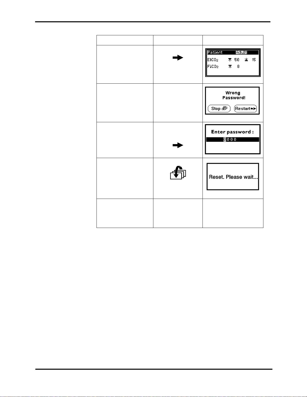
To access this service level, the service technician must enter a valid
password (1627), refer to Table 4-2.
Note: The password should not be disclosed to avoid unauthorized setting
of parameters.
Table 4-2: Accessing Service Level 2
Objective Action Response
To access Service
Level 2
Enter Password: 1627
Enter the 1st digit short press (right)
Move to the next digit short press
After entering the
service mode
long press x3
x1
Pressing on the
right arrow scrolls
the numbers up,
the left arrow
scrolls the numbers
down.
Password Screen
appears
Enter the 2nd digit short press (right)
x6
Repeat the same procedure as above for the next two digits (2, 7).
4-5
Page 20
Section 4: Service Mode
Table 4-2: Accessing Service Level 2 (Continued)
Objective Action Response
To access the Alarm
Limits Menu after
entering last password
digit
In case you entered a
wrong digit
To restart password
validation process
To reset and return to
measuring mode
(automatically erasing
event messages)
short press
long press
long press
To exit service mode
and save event
messages
Turn off the
monitor.
4-6
Page 21

4.3.1 Default Alarm Limits
The service technician can change the default alarm limits for either
patient mode (Adult or Neonatal).
The monitor has the follow ing alarms with adjustable level settings:
Section 4: Service Mode
• EtCO
•FiCO
2 high and low levels (mmHg)
2 high level (mmHg)
Refer to Table 4-3 for changing the settings of the above mentioned
parameters.
Warning: Changing default settings will permanently change the
user’s start up value and should be verified with the responsible
clinical personnel.
Table 4-3: Changing Default Alarm Limits
Objective Action Response
To access the Alarm
short press
Limits Menu after
entering last password
digit
To change the pati ent
short press
mode
To access a new
short press
parameter
To change the value short press
To reset and return to
long press
measuring mode
To exit service mode
and save event
Turn off the
monitor.
messages
4-7
Page 22

Section 4: Service Mode
4.3.2 Default Settings
The service technician can change two default settings (refer to Table 4-4):
• 3 Min Alert
• BTPS (body temperature, pressure, saturation)
When the 3 min Alert is ON, the unit will beep every three minutes to
remind the user that an alarm (or all alarms) are set to OFF.
When BTPS is ON, the CO
Table 4-4: Changing Default Settings
Objective Action Response
To access the Default
Settings Menu (after
accessing the Alarm
Limits Menu)
To change the setting short press
To access BTPS
parameter (and save
the changed setting)
2 value is corrected for this factor.
long press
short press
4-8
To reset and return to
measuring mode
To exit service mode
and save event
messages
long press
Turn off the
monitor.
Page 23

4.3.3 Flow Calibration
Section 4: Service Mode
The Flow Calibration screen allo ws the service technician to perform flow
calibration after flow ad justment and/or pump or flow system
replacement, refer to Table 4-5.
Table 4-5: Accessing Flow Calibration
Objective Action Response
To access the Flow
Calibration screen
To change the
parameter setting or
value
To move to the next
parameter (and save
the changed setting)
At any screen after
the password
long press
simultaneo u sly
and
short press
short press
4-9
Page 24

[This page intentionally left blank]
Page 25

SECTION 5: TROUBLESHOOTING
5.1 Introduction
5.2 Who Should Perform Repairs
5.3 Repair Level Supported
5.4 How to Use This Section
5.5 Obtaining Replacement Parts
5.6 Troubleshooting Guide
5.1 INTRODUCTION
This section provides information f or troubleshooting for the monitor
isolating a failure of the monitor.
5.2 WHO SHOULD PERFORM R EPAIRS
Only qualified service personnel should remove and replace components
of the monitor. If your facility does not have qualified service personnel,
contact your local distributor.
5.3 REPAIR LEVEL SUPPORTED
The monitor has the following replaceable components: CO2 board, Flow
System, Pump Assembly, Housing Components, LCD, 7-segment displays
and Software Assembly.
The procedures for disassembling and replacing the above mentioned
components are described in Section 7: Disassembly Guide.
5.4 HOW TO USE THIS SECTION
Failures of the Housing Compon ents; front cover, rear cover, gas outlet,
ON/OFF button and keypads, a re determined by visually i nspecting these
components for cracks or deformations, and checking for mechanical
failures.
Use the Troubleshooting Guide in Section 5.6 to isolate failures of the CO
board, Flow System, Pu mp Assembly, LCD and 7- segment displa ys. Once
a failure has been isolated, refer to Section 7: Disassembly Guide for
instructions for removing and replacing a component of the monitor.
5.5 OBTAINING REPLACEMENT PARTS
Your local distributor provides technical assistance informatio n and
replacement parts. Refer to parts by the part name listed in Section 13:
Spare Parts.
2
5-1
Page 26

Section 5: Troubleshooting
5.6 TROUBLESHOOTING GUIDE
If you encounter a problem that cannot be resolved through a visual
inspection, refer to Table 5-1 which provides a list of symptoms, pr obable
causes, and recommended actions to correct the proble m. It is
recommended that corrective actions be performed in the order presented.
For a symptom that is not listed in Table 5-1, contact your local
distributor.
If an Advisory mess age is displaye d on th e LCD, ref er to Table 5-2 for the
indicated failure and corrective action. Caution messages appear on the
display screen followed by !! and Advisory messages are followed by !.
Check in the Service Mode for any Event Messages and refer to Table 5-3
for the indicated failure and corrective action.
Symptom Probable Cause Corrective Action
Table 5-1: Troubleshooting Guide
The unit does not
turn on when the
ON/OFF button
is switched
when the unit is
operated with
batteries.
The unit does not
turn on when the
ON/OFF button
is switched
when the
monitor is
connected to
mains power.
ON
ON
The battery pack is
missing or is installed
incorrectly.
The battery pack’s
charge is low.
The battery pack’s
contacts are defective.
The contacts for the
battery pack on the
are defective or a
board
CO2
CO2 board component
has failed.
The ON/OFF button has
a mechanical defect.
Check if there is a
battery pack in the
monitor, if not, place
one in the monitor. Be
sure the battery pack
is installed correctly.
Install a fully charged
battery pack; charge
the empty battery
pack.
Install a new battery
pack and check the
monitor functions.
Connect the monitor
to mains line power
and if the monitor
functions, repla c e the
CO
2 board.
Inspect the button for
cracks, deformations
or other damage.
Replace with a new
button.
5-2
A CO
2 boa rd com ponent
has failed.
Replace with a new
2 board.
CO
Page 27

Section 5: Troubleshooting
Table 5-1: Troubleshooting Guide (Continued)
Symptom Probable Cause Corrective Action
The unit does not
turn on when the
ON/OFF button
is switched
ON
when the
monitor is
connected to
mains power.
One or more
buttons on the
upper or lower
keypad do not
work.
No information
is displayed on
the LCD.
The wall socket is not
receiving power or is
defective.
Check the wall socket
for power supply or
mechanical defects. If
necessary, use a
different wall socket.
The AC adapter is
defective.
A CO
2 boa rd com ponent
has failed.
Replace with new AC
adapter.
Replace with a new
2 board.
CO
The keypad is defective. Inspect the keypad for
cracks, deformations
or other damage.
Replace with a new
keypad.
A CO
2 boa rd com ponent
has failed.
The contrast default
value is set too lo w or
high.
Replace with a new
2 board.
CO
Check the contrast
value in the Service
Mode using the
Contrast Cal. option
and correct
accordingly.
LCD Backlight
does not come on
when the
monitor is placed
in a dark
environment.
An LCD component has
failed.
2 boa rd com ponent
A CO
has failed.
The Power
Management option is
set at
LOW.
An LCD component has
failed.
A CO
2 boa rd com ponent
has failed.
Replace with a new
LCD.
Replace with a new
CO
2 board.
Refer to the Handheld
Capnograph
Operator’s manual to
change the Power
Management option
to
NORMAL or
HIGH.
Replace with a new
LCD.
Replace with a new
2 board.
CO
5-3
Page 28

Section 5: Troubleshooting
Table 5-1: Troubleshooting Guide (Continued)
Symptom Probable Cause Corrective Action
7-Segment
Display does not
light when the
unit is
functioning.
Beeper does not
beep.
The Power
Management option is
set at
LOW.
A 7-Segment display
has failed.
A CO
2 boa rd com ponent
has failed.
One or more of the
Alarm Silence options
has been turned OFF.
2 component has
A CO
failed.
Refer to the Handheld
Capnograph
Operator’s manual to
change the Power
Management option
to
NORMAL or
HIGH.
Replace with new 7Segment display.
Replace with a new
2 board.
CO
Turn the respective
alarm
ON. Refer to
the Handheld
Capnograph
Operator’s manual.
Replace with a new
CO
2 board.
Table 5-2: Advisory Message
Message Probable Cause Corrective Action
Check Unit
! A CO2 boar d comp onent
has failed.
Check Event
Messages screen in
Service Mode.
5-4
Page 29

Section 5: Troubleshooting
Table 5-3: Event Messages
Event Message Probable Cause Corrective Action
CO
2 board
- Component Failed
Flow - Loose connections
- Kinks or twists in
tubing
- Flow system blocked
- Pump Malfunction - Replace pump
- A CO
2 board
component has failed
- Replace CO2 board
- Inspect all tubing
ends for loose
connections and
ensure tight
connections
- Straighten kinks
and undo any twists
in the tubing.
- Check flow rate and
if necessary change
Flow System, refer
to Section 6: Flow
Calibration Check
- Replace with a new
2 board
CO
5-5
Page 30

[This page intentionally left blank]
Page 31

SECTION 6: FLOW CALIBRATION CHECK
6.1 Introduction
6.2 Flow Rate Check
6.3 Flow Calibration Process
6.1 INTRODUCTION
Perform a Flow Calibration Chec k after replacing the Flow System and/or
Pump. Flow Calibration Check includes Flow Rate Check and Flow
Calibration Process.
6.2 FLOW RATE CHECK
To perform the Flow Rate Check, follow the steps below:
1. Connect the FilterLine to the Handheld Capnogr aph.
2. Turn on the monitor.
3. Connect the other end of the FilterLine to the Flow meter gas
outlet.
4. Access the Flow Calibration screen of the Service Mode, refer to
Section 4.3.3: Flow Calibration.
5. Check that the Flow Meter reading is 50 ±5 ml/min. (at sea level)
If the Flow Meter reading is 50 ±5 ml/min:
5a Perform Flow Calibration Process, refer to Section 6.3: Flow
Calibration Process.
If the Flow Meter reading is not 50 ±5 ml/min:
5b Change the pump voltage value until the flow rate displayed
in the flow meter is 50 ±5 ml/min, refer to Section 4: Service
Mode, Table 4-5: Accessing Flow Calibration.
5c Perform Flow Rate Check
5d Perform Flow Calibration Process.
If you cannot set the flow rate to 50 ±5 ml/min after adjusting the
pump voltage value:
5e Change the Flow System, refer to Section 7.5: Replacing the
Flow System.
5f Perform Flow Rate Check
5g Perform Flow Calibration Proc ess.
If after changing the Flow System you still cannot set the flow rate
display in the flow meter to 50 ±5 ml/min:
5h Change the Pump, refer to Section 7.4: Replacing the Pump.
5i Perform Flow Rate Check
5j Perform Flow Calibration Process.
6-1
Page 32

Section 6: Flow Calibration Check
6.3 FLOW CALIBRATION PROCESS
To perform the Flow Calibration Process, refer to Table 6-1.
Objective Action Response
Table 6-1: Flow Calibration
To access Flow
Calibration screen
Simultaneously
long press
and
To select Flow Cal. short press
To start Calibration short press
short press
6-2
Wait until either a Fail or Pass message is displayed
If FAIL is displayed Replace Flow
System and/or
Pump
(refer to Section 5:
Troubleshooting)
and repeat above
procedure
If PASS is displayed Exit Service Mode
Page 33

Section 6: Flow Calibration Check
Table 6-1: Flow Calibration(Continued)
Objective Action Response
To reset and return to
measuring mode
To exit service mode
and save event
messages
long press
Turn off the
monitor
6-3
Page 34

[This page intentionally left blank]
Page 35

SECTION 7: DISASSEMBLY GUIDE
7.1 Introduction
7.2 Opening the Handheld Capnograph Case
7.3 Replacing the CO
7.4 Replacing the Pump As se m b ly
7.5 Replacing the Flowing System
7.6 Replacing the LCD and 7-Segment Display
7.7 Replacing the Housing Components
7.8 Updating the Software Version
7.1 INTRODUCTION
The monitor can be disassembled and the following components can be
replaced:
2 Board
•CO
• Pump Assembly
•Flow System
• Housing components
• EPROM
• Liquid Crystal Display (LCD)
• 7-segment displays
Caution: Observe ESD (electrostatic discharge) precautions when
disassembling and reassembling the moni tor a nd when handli ng
any of its components.
Use the following procedures to disassemble the monitor and replace
parts as needed. Reassemble the monitor in reverse order. The
manufacturer recommends that you follow the disassembly procedure in
the order p r esented.
Note: After replacing the Flow System and/or Pump, perform a flow
Note: After reassembling any part of the monitor, be sure to complete the
2 board
calibration check as described in Section 6:
performance verification as described in Section 10: Performance
Verification.
Flow Calibration Check.
7-1
Page 36

Section 7: Disassembly Guide
7.2 OPENING THE HANDHELD CAPNOGRAPH CASE
1. Be sure the monitor is disconnected from mains power and remove
the battery pack from the monitor; push the release button at the
bottom of the monitor and pull out the battery pack as shown in
Figure 7-1.
7-2
Figure 7-1: Removing the Battery Pack
Page 37

Section 7: Disassembly Guide
2. Place the monitor on a clean, dry nonabrasive su rface with the back
of the monitor facing up.
3. Remove the two bottom and two back mounting screws from the
rear panel of the monitor as sh own in Figure 7-2.
Figure 7-2: Removing Mounting Screws
4. Carefully lift the rear case cover up as shown in Figure 7-3.
Figure 7-3: Separating Rear and Front Covers
7-3
Page 38

Section 7: Disassembly Guide
7.3 REPLACING THE CO2 BOARD
1. Open the monitor case as de scribed in Section 7.2.
2. Remove the two CO
3. Remove the CO
2 board mounting screws.
2 connector screw from the CO2 input connector.
4. Remove the ON-OFF button and save for reassembly.
5. Remove the gas outlet from the tubing and save for reassembly.
6. Remove the CO
2 board and replace with a new CO2 board and
reassemble in reverse order .
Warning: The scrubber on the CO
2 board is a lithium based
compound. Follow local governing ordinances for disposal.
7-4
Figure 7-4: Replacing CO2 Board and Housing Components
Page 39

7.4 REPLACING THE PUMP (REFER TO FIGURE 7-5)
1. Open the monitor case de scribed in Section 7.2.
2. Remove the damping cover from the pump.
3. Locate the two tubings, Main line and Exhaust line, connected to
the pump, refer to Figure 7-6.
4. Locate the purple Main line restrictor and the green Exhaust line
restrictor.
5. Disconnect both tubings from their restrictors.
Note: Both restrictors must remain with their flow system lin es attached
to the CO
2 board.
Section 7: Disassembly Guide
6. Disconnect the pump connector from it’s CO
7. Remov e the CO
2 board from the front cover, refer to Section 7.3.
2 board socket.
8. Unscrew and remove the pump mounting screws.
9. Remove the lower damping and damping holder.
10. Remove the pump and the upper damping .
11. Place the new Pump.
12. Reassemble the unit, using the new assembly parts, in reverse
order.
Note: Before replacing the pump mounting screws, first dip them into
Loctite
®
glue or any other threadlocker glue. Carefully twist the
screws into the lower damping, gently pressing against the
CO
2 board..
Figure 7-5: Replacing the Pump
7-5
Page 40

Section 7: Disassembly Guide
7.5 REPLACING THE FLOW SY STEM
1. Open the monitor case as de scribed in Section 7.2.
The Flow System has 5 lines, refer to Figure 7-6.
Two lines go from the pump:
• M ai n li ne
•Exhaust line
Three lines go from the solenoid :
•Zero line
• Input Line1
• Input Line2
7-6
Figure 7-6: Flow System
Page 41

7.5.1 Replacing the lines to the pump
7.5.1.1 Replacing the Main line (Refer to Figure 7-7)
1. Locate the purple restrictor.
2. Carefully disconnect the main line from the tubing
connected to the pump, leaving the purple restrictor in the main
line.
Section 7: Disassembly Guide
3. Remove the tubing from the CO
2
sensor.
4. Remove the tubing from the pressure sensor.
Note: When replacing the main line, in order to fit the main line on the
board without twists and kinks, coil
the tubing around the
pressure sensor (refer to Figu re 7-8).
5. Reassemble the new Main line in reverse order.
Figure 7-7: Main line
7.5.1.2 Replacing the Exhaust line (Refer to Figure 7-8)
1. Locate the green restrictor.
2. Carefully disconnect the Exhaust line, at the green restrictor,
from the tubing connected to the pump. Leave the green
restrictor in the exhaust line.
3. Reassemble the new Exhaust line in reverse order.
Figure 7-8: Exhaust line
7-7
Page 42

Section 7: Disassembly Guide
7.5.2 Replacing the lines to the solenoid (Refer to Figure 7-9)
7.5.2.1 Removing lines to the solenoi d
1. Carefully disconnect the Zero line from the solenoid.
Warning: The scrubber on the Zero line is a lithium based
compound. Follow local governing ordinances for disposal.
2. Remove Input line 1 from the solenoid and the other end from
the FilterLine input connector.
3. Remove Input line 2 from the solenoid and the other end from
the sensor connector.
Figure 7-9: Lines to Solenoid (Zero line, Input line 1, Input line 2)
7-8
Page 43

Section 7: Disassembly Guide
7.5.2.2 Reassembly of the new solenoid lines.
1. Attach the new Input line1 to the upper solenoid connector.
2. Locate the lower solenoid connector which is closest to the
sensor and attach the new Input line 2 to this connector.
3. Bring the Input line 2 tubing over Input line 1, and attach to the
sensor connector.
4. Lead the Input line 1 under the FRS cables (connected to the
FilterLine input connector, not viewed in Figure 7-9) and
connect to the FilterLine input tubing connector.
5. Connect the Zeroline to its sole noi d connector and place the
scrubber close to the pump under the coiled main line tubing,
refer to Figure. 7-10.
Figure 7-10: Zero line
7-9
Page 44

Section 7: Disassembly Guide
7.6 REPLACING LCD AND 7-SEGMENT DISPLAY (REFER TO FIGURE 7-11)
7.6.1 Replacing the LCD
1. Remove the CO2 board as described in 7.3.
2. Unscrew and remove the four LCD mounting screws.
3. Carefully remove the LCD and replace with a new LCD.
7.6.2 Replacing the 7-Segment Display
1. Remove the CO2 board as described in Section 7. 3.
2. Carefully remove the faulty 7-segment display from its socket and
replace with a new 7-segment display. Note the correct
orientation of the 7-segment display when replacing it.
7-10
Figure 7-11: Replacing LCD and 7-Segment Display
Page 45

7.7 REPLACING HOUSING COMPONENTS
The Housing kit includes the following replaceable components:
• Front cover
• Rear cover
•ON/OFF switch
• Upper Keypad (Alarm silence button and Contrast/Value change
button)
• Lower Keypad (Print/Home button and Next/Menu button)
• Gas outlet
•Screws
•Washers
Note: When reassembling the monitor after replacing any part, be sure to
follow the disassembly steps in reverse order.
7.7.1 ON/OFF Button and Gas Outlet (Figure 7-4)
1. Open the monitor as described in Section 7.2.
2. Remove the gas outlet from the tubing and replace with a new gas
outlet.
Section 7: Disassembly Guide
3. Remove the ON/OFF button from the CO
Section 7.3 and replace with a n ew button.
7.7.2 Keypads (Figure 7-4)
1. Open the monitor as described in Section 7.2.
2. Remove the CO
3. Remove the old keypad. When replacing the new keypad, be sure
the icons are facing the correct direction, refer to
Figure 1-1.
7.7.3 Front Cover (Figure 7-4)
1. Open the monitor as described in Section 7.2.
2. Remove the CO
3. Remove the keypad and ON/OFF button. Place them in the new
front cover. When replacing the keypad, be sure the icons are facing the correct direction, refer to Figure 1-1.
4. Place the CO
7.7.4 Rear Cover (Figure 7-3)
1. To replace the rear cover, open the monitor as described in
Section 7.2. and replace the old rear cover with a new rear cover.
2 board as described in
2 board as described in Section 7.3.
2 board as described in Section 7.3.
2 board in the new cover.
7-11
Page 46

Section 7: Disassembly Guide
7.8 UPDATING SOFTWARE VERSION
Caution: Observe ESD (electrostatic discharge) precautions when
disassembling and reassembling the monitor and when handling
any of the components of the monitor.
1. Open the monitor as described in Section 7.2.
2. Remove the EPROM from its socket (on the CO
2 board) using an IC
extractor, refer to Figure 7-12.
3. Insert the new EPROM.
Note: When replacing the EPROM, be sure it is positioned correctly.
Note: When operating the monitor for the first time after updating the
software version, the warm-up and the self-test periods will be
longer than usual.
7-12
Figure 7-12: Replacing EPROM
Page 47

SECTION 8: ELECTRICAL SAFETY TESTS
8.1 Electrical Safety Tests
8.1 ELECTRICAL SAFETY TESTS
Do not return the monitor to the user until the conditions in the following
“Warning” statement are met.
Warning: After servicing the monitor, always verify product
performance per the procedures in Section 10: Performance
Verification and perform any safety tests required by local
regulatory bodies or mandated by your institution.
8-1
Page 48

[This page intentionally left blank]
Page 49

SECTION 9: PERIODIC MAINTENANCE
9.1 Periodic Maintenance
9.1 PERIODIC MAINTENANCE
Periodic maintenan ce is recommended according to ope rating hours (r efer
to section 4.2 "Service Level 1"):
The Pump and Flow System should be replaced every 7,000 operating
hours.
For replacing the pump, refer to section 7.5 "Replacing the Pump".
For replacing the flow system, refer to section 7.6 "Replacing the Flow
System".
The monitor should be returned to the manufacturer for periodic
maintenance every 14,000 operating hours.
9-1
Page 50

[This page intentionally left blank]
Page 51

SECTION 10: PERFORMANCE VERIFICATION
10.1 Flow System Leak Check
10.2 Performance Verification Procedure
The performance of the monitor must be verified after all service procedures. Perform all
procedures in this section to verify the correct functioning of the monitor.
10.1 FLOW SYSTEM LEAK CHECK
Perform the Flow System Leak Check after all service procedures
described in this manual.
10.1.1 Flow System Leak Check Procedure
1. Connect the vacuum manometer to the Leak Test Jig as shown in
Figure 10-1.
Figure 10-1: Leak Test Jig Connection
2. Open the Leak Test Jig clamp and empty the syringe’s contents.
3. Connect the open-ended tubing ( as shown in Figure 10-1) of the
Leak Test Jig to the Gas Outlet of the monitor.
4. Connect the other open-ended tubing of the Leak Test Jig to the
CO
input connector.
2
5. Pull the syringe valve out until the pressu re drops (as displayed on
the vacuum manometer) to approximately -300 mBar (or
equivalent) and close the clamp.
6. Wait 30 seconds.
7. The change in reading should be less tha n 20 mBar (or equi val ent).
10-1
Page 52

Section 10: Performance Verification
8. If the reading drops more than 20 mBar, there is a leak in the flow
system.
•Open the unit.
• Check for loose fittings and if any are found, reconnect
them.
• Repeat the above process (steps 1-7).
• If the readin g continues to show a drop of more than 20
mBar, replace the Flow System, refer to Section 7-5.
10.2 PERFORMANCE VERIFICATION PROCEDURE
Verify the performance of the monitor using the following procedure.
1. Connect the monitor to mains supply using the AC adapter.
2. Connect the FilterLine to the monitor.
3. Turn ON the monitor.
4. The Initialization Screen appears and the
Self-Test bar fills, refer to Figure 10-2.
5. Verify that an audio tone sounds. This
verifies proper operation of the Alarm
interfacing. Check that the LEDs on the
Figure 10-2:
Initialization Screen
alarm bar turn red, yellow and th en off. The
7-segment display shows 8s moving from
left to right.
6. After initialization, the monitor
automatically goes to Measuring Mode. The
message CO
2 Warmup appears on the Silent
Advisory Message area, refer to
Figure 10-3.
7. After CO
changes to Ready.
2 Warmup, verify that the message
Figure 10-3: Measuring
Mode
Note: If BTPS is on, then the message will read BTPS ON-Ready.
8. Disconnect the FilterLine and verify that the message FilterLine
is displayed on the Silent Advisory Message Area and verify that
the pump stops.
9. Reconnect the FilterLine and verify that the message FilterLine
disappears and the pump is operating.
10-2
Page 53

Section 10: Performance Verification
10. Verify that all buttons on the unit work properly. Refer to the
Quick Guide for their applicati ons, see Figure 10-4.
Power On
Short Press
Changes Displays /
Selects Par a me ters
Event Mark
Changes
Values / Contrast
Sound ON / OFF
Long Press
Accesses
Menus
Home /
Erase Trend
Quick Scroll
Accesses
Alarm Menu
Data Trans fe r
ON / OFF
Figure 10-4: Quick Guide
11. Verify the CO
2 Calibration Check process functions. Fol low the
procedure as described below. When completed, return to the
Measuring Mode screen.
CO
2 Calibration Check
Caution: Do not check CO
2 values from the measurin g mode if th e
BTPS setting is ON (factory default). This mode corrects the CO
value for BTPS. The calibration check mode disables this
correction.
In order to ensure accuracy, a CO
2 calibration check nee ds to be done once
a year. Calibration gas and a FilterLine are needed for this procedure.
Start the process from the Interface Test Screen (refer to Table 4-2) as
follows in Table 10-1.
2
Note: Connect the FilterLine to the monitor be fore starting CO
Table 10-1: CO2 Calibration Check
Objective Action Result
Access CO
2
short press (x3)
Calib.
Change option
short press
to start.
2 Calibration Check.
10-3
Page 54

Section 10: Performance Verification
Table 10-1: CO
2 Calibration Check (Continued)
Objective Action Result
Start Check
short press
Cal. An
Autozero
process
automatically
occurs.
Autozero is
complete;
“Connect Gas”
is displayed.
1. Wait 20
minutes to
reach steady
state of
temperature.
2. Connect the
FilterLine to
calibration
gas.
Check the
measured
values shown in
Vol% in the
EtCO
2 digital
Press the gas
valve for 15
seconds until
the readings
stabilize.
display.
PLQ
Calibration is not required if the measured value is the
same as the concentration of the calibration gas (±0.5%)
e.g. Concentration of calibration gas used is 5% (CO
2); the
measured value should be between 4.8%-5.2%, therefore,
calibration is not required.
To reset and
long press
return to
measuring
mode
To exit service
mode and save
Turn off the
monitor.
event messages
If the reading is outside these limits, calibration is
required. Refer to Table 10-2 for the calibration process
procedure.
10-4
Page 55

Section 10: Performance Verification
Calibration Process
If calibration is required, perform the Calibration Process (after
performing Calibratio n Check) as shown in Table 10-2
Note: The manufacturer recommends using calibration gas, 5% CO
air.
Table 10-2: Calibration Process
Objective Action Result
To start
Calibration
No action
required.
PLQ
Process after
calibration check.
To activate
long press
Calibration
Process.
To adjust the
short press
display value to
the gas
concentration you
are using.
2 in
To start
calibration.
Monitor performs
an internal
calculation.
Calibration
succeeded.
Return to
calibration check
mode.
Press the gas
valve and
long press
Continue
pressing the
gas valve until
the “Disconnect
Gas” appears.
Disconnect Gas
from the
FilterLine.
No action
required.
long press
10-5
Page 56

Section 10: Performance Verification
Objective Action Result
Table 10-2: Calibration Process (Continued)
To reset and
return to
measuring mode
To exit service
mode and save
event messages
long press
Turn off the
monitor.
Calibration Errors
Table 10-3 describes calibration problems that can occur, the message
displayed and the corrective action.
Table 10-3: Calibration Process - Troubleshooting
Message Possible Causes Action
• Gas concentra tion
does not match the
concentration value
selected in the first
calibration screen.
• Problems wi th gas
sampling
•Flow system
problems (purging,
blockage or no
FilterLine)
Check setup,
correct
probable
causes, and
recalibrate
unit as
above.
10-6
•CO
2 Sensor problem
• Calibration process
exceeds 3 minutes
•Contact
your local
distributor.
•Restart. If
the
problem
persists,
contact
your local
distributor.
12. Disconnect the monitor from the AC mains supply. Verify the unit
continues to work from its ba ttery pack and the battery icon appear s
on the lower right corner of the display.
13. Reconnect the monitor to mains power with the AC adapter. Verify
that the unit functions, and the plug icon appears.
Note: If the battery pack has a l ow charge level, the battery i con will
appear instead of the plug. The battery icon will fill indicating the
battery charging process.
Page 57

Section 10: Performance Verification
To verify printing functions:
14. Adjust the printer to the following communication settings:
Input Serial
Data Length 8 bits
Parity Settings None
Baud 9600 bps
15. Using the Communication Adapter Kit, connect the printer to the
monitor, refer to Figure: 10-5.
Figure 10-5: Connecting the monitor to Printer/PC with
Communication Adapter Kit
16. Turn the printer ON and select on-line mode.
10-7
Page 58

Section 10: Performance Verification
17. Access the monitor print functions as d escribed in Ta ble 10 -4 below:
Table 10-4: Accessing Handheld Capnograph Print Functions
Objective Action Result
To access the
Instrument Setup
menu (first access
the Alarm Limits
menu from any
measuring display)
To select Print short press (x2)
Be sure the Print
option shows
long press (x2)
short press
Screen; if it doesn’t,
change to the
option
To return to
Measuring Mode
Screen
long press
To print long press
simultaneo usly
and
(printout)
10-8
Page 59

SECTION 11: PACKING FOR SHIPMENT
11.1 General Instructions
11.2 Packing Handheld Capnograph in Original Carton
11.3 Packing in a Different Carton
11.1 GENERAL INSTRUCTIONS
To ship a monitor or one of its compo nents for any reason, follow the
instructions in this section. Failure to follow the instructions in this
section may result in loss or damage not covered by any applicable
manufacturer warranty.
Pack the monitor or co mponent(s) carefully. If available, use the original
carton and packing materials and follow the instructions in “Packing
monitor in Original Carton. ” If th e ori ginal sh ipp ing carton and mate rial
are not available, u se other suitable shi pping materials an d container and
follow the instructions in “Packing in a Different Carton.”
Prior to shipping the monitor or a component, contact your local
representative for a Returned Material Authorization (RMA) number.
Mark the shipping carton and any shipping forms with the RMA and the
monitor’s seria l number.
Caution: Observe ESD (elect rostatic discharge) precautions when
packing any monitor components.
11.2 PACKING HANDHELD CAPNOGRAPH IN ORIGINAL CARTON
If the original carton and packing material are available, repack the
monitor as follows. (Refer to Figure 11-1.)
1. Place the unit in a plastic bag. Place it into the co rresponding
space, in the original foa m padding, wi th th e fron t panel fa cin g up.
2. Place the foam padding cover over the top of the unit.
3. Seal the carton with packing tape.
4. Label the carton with the correct shipping address, return address
and RMA number.
11.1 PACKING IN A DIFFERENT CARTON
If the original carton and packing materi al are not available or if shipping
any monitor component not in its original carton:
1. Place the monitor in a plastic bag or component in a plastic anti-
static bag.
2. Locate a corrugated cardboard shipping carton (approximately the
size of the monitor or component) with at least 200 pounds per
square inch (psi) bursting strength.
3. Fill the bottom of the carton with at least 2 inches of packing
material.
11-1
Page 60

Section 11: Packing For Shipment
4. Place the bagged monitor or component on the layer of packing
5. Seal the carton with packing tape.
6. Label carton with shipping address, return address and RMA
material and fill the box completely with packing material such
that there is at least 2 inches of packi ng material around all sides
of the item.
number.
Top padding
Plastic bag
Handheld Capnograph
Foam padding
Shipping Carton
Figure 11-1: Packing the Handheld Capnograph in
Original Packing
11-2
Page 61

SECTION 12: SPECIFICATIONS
12.1 Physical
12.2 Environmental
12.3 Safety Standards
12.4 Performance
12.5 Power Specifications
12.6 Components and User Interface
12.1 PHYSICAL
12.1.1 Size
206 mm H x 88 mm W x 53 mm D (8.11”H x 3.46” W x 2.06”D)
12.1.2 Weight (including battery pack)
750 grams (1.66 lb.)
12.1.3 Noise Emission
maximum 45 dB(a)
12.2 ENVIRONMENTAL
12.2.1 T e mperature
Operating
Storage
12.2.2 Relative Humidity
o
C to 45oC (32oF to 113oF)
0
o
C to 70oC (-31oF to 158oF)
-35
10 to 95% (noncondensing)
12.2.3 Pressure and Altitude (for operating and storage).
Pressure 430 mmHg to 795 mmhg
Altitude -380m to 4,570m (-1,250 ft. to 15,000 ft)
12.3 SAFETY STANDARDS
The monitor was designed to comply with EN60601-1/1990, A1/1993,
A2/1995, EN60601-1-1/1992, A1/1996, UL 2601-1 and CSA 22.2 No. 601.1M90, EN864/1997.
12-1
Page 62

Section 12: Specifications
12.4 PERFORM ANCE
Sampling Ra te 50 ±7.5 ml/min
CO
2 Range 0-99 mmHg (0-13.2 kPa and 0-13.0 Vol%) at sea
level
Accuracy
EtCO
2 readings
The CO
2 reading reaches its steady state accuracy
20 minutes after power up.
0 - 38 mmHg: (±2 mmHg)
39 - 76 mmHg: (±5% of reading)
77 - 99 mmHg: (±8% of reading)
From power-up until steady state is reached, the
CO
2 reading accuracy is:
0 - 38 mmHg: (±4 mmHg)
39 - 76 mmHg: (± 12% of reading)
77 - 99 mmHg: (± 12% of reading)
Equivalent values for kPa and Vol%
Respiration Rate
0-150 breaths/min.
Warm-up Time 30 seconds (typical)
Frequency
Response
EtCO
2 accuracy is maintained up to 80 breaths/
min. (For maintaining accura cy for respirat ion rate
over 60 bpm, use the neonatal mode.) From 81 to
150 bpm accuracy is ±12%, if the EtCO
2 is higher
than 18.8 mmHg in neonatal mode.
System
2.45 seconds (typical), 2.9 seconds maximum
Response Time
(delay time)
Ambient
Compensated internally - automatic
Pressure
Alarms EtCO
2 high*, EtCO2 low*, FiCO2 high*, Apnea
message
* The accuracy of these alarms is the same as the accuracy of the EtCO2
readings.
12-2
Page 63

12.5 POWER SPECIFICATIONS
12.5.1 External Pow er Sourc e
12V DC Medical Grade Adapter
12.5.2 Internal Power Source
Ni-MH Rechargeable Battery Pack 7.2V 2.1 A/h (intended for continuous
operation)
Section 12: Specifications
Operating Time
(fully charged)
Recharging
Period
Charger Type Internal
12.6 COMPONENTS AND USER INTERFACE
12.6.1. Displays
Graphic LCD
display
Two numeric
fields
Two-color alarm
3 digits each, using 7-segment LED dimension
22mm x 14 mm.
yellow, red
bar
12.6.2 Controls and Indicators
Between 3 and 6 hours, depending on power
management.These values refle ct the pe rformance
of a new battery; age and usage will degrade
capacity.
Approximately 4.5 hours internal recharging
(128 x 64 dots) with LED backlight dimension
75 mm x 53 mm.
12.6.3 Connections
Front Panel ON/OFF switch; Alarm Silence button; Contrast/
Value change button; Event/Home button; Next/
Menu button.
Front Panel CO
2 Input connector
Rear Panel Clamp connector
Side Panel Power Supply/Communication Adapter Port, Gas
output connector
12-3
Page 64

[This page intentionally left blank]
Page 65

SECTION 13: SPARE PARTS
13.1 Spare Parts List
13.1 SPARE PARTS LIST
Spare parts are shown belo w in Table 13-1. For spare part numbers
contact your local distributor.
Item Description
Table 13-1: Spare Parts List
1
CO
2 board - includes electronic board, sensor, pump
and scrubber, solenoid, LCD, 7-segment display, flow
system, CO
2 input connector, software EPROM and
screws.
2 Software Assembly - includes EPROM chip and last
updated software version.
3 Housing Kit - includes front cover, rear cover,
ON/OFF button, keypads, gas outlet, screws
4 7-Segment Digital Display (x2)
5 LCD Assembly - Graphic Display Screen and PC
driver
6 Calibration Gas (5% CO
2 in air)
7 Leak Test Jig - vacuum test accessories
8 Communication Adapter Kit
9 Battery Pack
10 Pump Assembly
11 Flow System
13-1
Page 66

GLOSSARY OF TERMS
BIT: Built in Tests.
BTPS: Body Temperature, Pressure and Saturation
EPROM: Erasable Programmable Read Only Memory.
Compensation.
Where Body Temperature is assumed 37°C with
vapor pressure 47mmHg
The Calculations are made according to:
P
CO2
= F
x (Pb - 47)
CO2
Where:
F
is the Fractional concentration of CO2 in
CO2
Dry gas, F
= % CO2/100
CO2
Pb = the ambient pressure
P
= the partia l p r es sure of CO2 at BTPS
CO2
ESD: Electrostatic Discharge.
EtCO
: End Tidal Carbon Dioxide: amount of CO2 present
2
at the end of the exhalation.
FiCO
: Fractional Inspired Carbon Dioxide: amount of
2
present during inhalation.
CO
2
FRS: FilterLine Recognition Safeguard .
LCD: Liquid Crystal Display.
HMI: Human Machine Interface.
Respiration Rate: Number of respiratory cycles (inhal ation and
exhalation) per minute.
7-segments LED: Graphic display of seven segments of light emitter
diodes.
Solenoid: 2-way electro-pneumatic valve controlling the
directional flow either from th e patient or from the
CO
Scrubber (during Autozero).
2
Scrubber: Lithium compound CO
absorber.
2
 Loading...