

Page 1
Page 2

Nellcor Puritan Bennett Inc. is an affiliate of Tyco Healthcare. Nellcor, Oxiband, Durasensor,
OxiCliq, Dura-Y, MAX-FAST, and O
XIMAX are trademarks of Nellcor Puritan Bennett Inc.
This ISM device complies with Canadian ICES-001.
Cet appareil ISM est conforme à la norme NMB-001 Canada.
To obtain information about a warranty, if any, contact Nellcor’s Technical Services Department,
or your local representative.
Purchase of this instrument confers no express or implied license under any Nellcor Puritan
Bennett patent to use the instrument with any sensor that is not manufactured or licensed by
Nellcor Puritan Bennett.
Page 3

Contents
Contents . . . . . . . . . . . . . . . . . . . . . . . . . . . . . . . . . . . . . . . . . . . . . . . . . . . . . .i
Safety Information . . . . . . . . . . . . . . . . . . . . . . . . . . . . . . . . . . . . . . . . . . . . . 1
Safety Warnings ................................................................................1
Safety Cautions .................................................................................3
Introduction . . . . . . . . . . . . . . . . . . . . . . . . . . . . . . . . . . . . . . . . . . . . . . . . . . . 5
Intended Use .....................................................................................5
How to Use this Manual ....................................................................6
Symbols, Controls, Displays and Indicators . . . . . . . . . . . . . . . . . . . . . . . . . . 7
About the Front Panel .......................................................................7
About the Rear Panel ........................................................................8
About the Symbols ............................................................................9
About the Controls ..........................................................................10
About the Displays ..........................................................................11
Pleth Display .........................................................................11
Blip Display ..........................................................................12
Real-Time Trend Display ......................................................14
SpO2 and Pulse Rates .........................................................14
About the Visual Indicators .............................................................16
About the Audible Indicators ...........................................................19
Setting Up the Monitor . . . . . . . . . . . . . . . . . . . . . . . . . . . . . . . . . . . . . . . . . 21
List of Components .........................................................................23
Connecting to an AC Power Source ...................... ... ... ... ... .... ... ... ...24
Connecting an OXIMAX Sensor ...................... ... .... ... ... ... ... .... ... ... ...26
Operating the Battery . . . . . . . . . . . . . . . . . . . . . . . . . . . . . . . . . . . . . . . . . . 27
Operating on Battery Power ......................... ...................................27
Low Battery Indicator ............... .... ... ................................................29
Description of Low and Critical Battery Conditions ...............30
Battery Fuel Gauge Indicator ................................................34
Using the Monitor . . . . . . . . . . . . . . . . . . . . . . . . . . . . . . . . . . . . . . . . . . . . . 35
Overview ......................................................................................... 35
Menu Description .. ... .... ... ... ... ... .... ... ... ....................................... ... ...35
Menu Structure .....................................................................36
Parameter Ranges ..........................................................................40
Turning On the Monitor ...................................................................43
N-600x Operator’s Manual i
Page 4

Contents
OXIMAX Sensor Attached .................................................... 45
No OXIMAX Sensor Attached .............................................. 49
Turning the Backlight On or Off ...................................................... 50
Adjusting the Screen Contrast ........................................................ 50
Adjusting the Backlight Brightness ................................................. 50
Selecting the Pleth View ................................................................. 51
Selecting the Blip View ................................................................... 51
Selecting the Real-Time Trend View .............................................. 52
Selecting the Trend Data Display ......................................... 53
Setting the Trend Time Scale Display .................................. 53
Setting the Trend Amplitude Scale Display .......................... 54
Setting the Pulse Beep Volume .......................................... ... ... ... ... 54
Setting the Alarm Volume .. .... ... ... ... ... .... ... ... ... .... ... ... ... ... .... ... ... ... ... 55
Setting the Date and Time...................................... ... ... ... .... ... ... ... .. 56
Setting the Alarm Silence Duration ........................... ... ... .... ... ... ... ... 58
Disabling Audible Alarms ................................................................ 59
Selecting the Standby Mode ........................................................... 60
Adult-Pediatric or Neonatal Settings ............................ ................... 61
Setting Patient Adult-Pediatric or Neonatal Modes .............. 62
Alarm Limit Changed Indicator ....................................................... 63
Setting Alarm Limits ............................... ... ... ... .... ... ... ... ... ................ 63
Setting SatSeconds Alarm Limit ........ .... ... ... ... .... ... ... ... ... .... ... ... ... ... 65
Setting Monitor Response Mode .............. ... ... .... ... ... ... ... .... ... ... ... ... 66
Selecting the Display Language ..................................................... 68
OXIMAX Sensor Messages ............................................................ 69
OXIMAX Sensor Adjust Condition Messages ...................... 70
OXIMAX Sensor Adjust Messages ....................................... 71
Using Monitor Trend Data . . . . . . . . . . . . . . . . . . . . . . . . . . . . . . . . . . . . . . .73
Overview ................................... ................................................ ...... 73
Storing Trend Data ............................................................... 75
OXIMAX Sensor Type .................................................................... 76
Selecting the Trend Data Display Scale ......................................... 76
Reading the Trend Data Display ............................ ................... ...... 78
Dual Trend Data Display ................................................................. 79
SpO2 Trend Display ....................................................................... 80
Pulse Rate Trend Display ............................................................... 80
Histogram Trend Data Display .................. ... ... .... ... ... ... ... .... ... ... ... ... 81
Pulse Amplitude Trend Data Display .............................................. 82
Clearing Trend Information ............................................................. 83
Using OXIMAX Sensor Event Records . . . . . . . . . . . . . . . . . . . . . . . . . . . . .85
Overview ................................... ................................................ ...... 85
Setting up OXIMAX Sensor Messages ........................... .... ... ... ... ... 87
ii
Page 5

Setting In-Sensor Data Type ...........................................................88
OXIMAX Sensor Data Type ............................................................89
OXIMAX Sensor Event Record Data Available ...............................90
OXIMAX Sensor Event Record Not Available .................................91
OXIMAX Sensor Event Record Graphical Data ........................... ...92
Viewing and Printing OXIMAX Sensor Event History Data .............94
OXIMAX Sensor Tabular Event Data ..............................................96
Viewing and Printing In-Sensor Tabular Event History Data ...........97
Printing Monitor Trend Data . . . . . . . . . . . . . . . . . . . . . . . . . . . . . . . . . . . . . 99
Overview ......................................................................................... 99
Printing ..................................... .................... ................... ......99
Monitor Trend Data in ASCII Mode ...............................................102
Trend Data in Graph Mode ...........................................................103
Real-Time Display/Printout Format ...............................................103
Column Headings ...............................................................105
Data Source ........................................................................105
Software Version ........ ... .... ... ... ... .... ....................................106
Alarm Limits ........................................................................106
Monitor Mode ........................ ... ... .... ... ... ... .... .......................106
Response Mode ..................................................................107
Data Column Headings .......................................................107
Time ...................................... ..............................................108
Patient Data .................................... ... ... ... .... .......................108
Operating Status ......................... .... ... ... ... .... ... ... ... ... .... ... ... .108
Using the Data Port . . . . . . . . . . . . . . . . . . . . . . . . . . . . . . . . . . . . . . . . . . 111
Overview ....................................................................................... 111
Connecting to the Data Port ..........................................................112
Data Port Pinouts ................................................................112
Data Port Setup .............................................................................114
Using the Nurse Call Interface ......................................................116
Setting Nurse Call RS-232 Polarity .......... .... ... ... ... ... .... ... ... .117
Setting Nurse Call Relays Normally Open/Closed ..............118
Calculating the Analog Voltage Output .........................................118
OXIMAX Sensors and Accessories . . . . . . . . . . . . . . . . . . . . . . . . . . . . . . 121
Overview ....................................................................................... 121
Selecting an OXIMAX Sensor .......................................................122
OXIMAX Sensor Features .............................................................126
Biocompatibility Testing ................................................................126
Optional Accessories ................... .......................................... ... ... .127
GCX Mounting Plate ...........................................................128
GCX Vertical Wall Mount Arm ............................................129
N-600x Operator’s Manual iii
Page 6

Contents
GCX Roll Stand .................................................................. 130
Soft-Sided Carrying Case ................................................... 131
Performance Considerations . . . . . . . . . . . . . . . . . . . . . . . . . . . . . . . . . . . .133
Overview ................................... ................................................... .133
Performance Considerations .......................................... .... ... ....... 134
Dysfunctional Hemoglobins ................................................ 134
Anemia ............................................................................... 135
Saturation ........................................................................... 135
Pulse Rates ........................................................................ 135
OXIMAX Sensor Performance Considerations ............................. 135
Troubleshooting . . . . . . . . . . . . . . . . . . . . . . . . . . . . . . . . . . . . . . . . . . . . . .139
Overview ................................... ................................................... .139
On-Screen Help ..................................... ... .................................... 140
Accessing Multiple Topics .................................................. 140
Accessing Single Topics .................................................... 143
Error Codes .................................................................................. 145
Prompts and Error Messages ....................................................... 148
Primary Speaker Failure ............................................................... 151
Help and Support ................................... ... ... ... .... ... ... ... ... .... .......... 153
EMI (Electromagnetic Interference) .............................................. 158
Obtaining Technical Assistance .................................................... 159
Returning your Monitor ....................................................... 159
Maintenance . . . . . . . . . . . . . . . . . . . . . . . . . . . . . . . . . . . . . . . . . . . . . . . .161
Overview ................................... ................................................... .161
Service ................................... ................................................ ....... 161
Periodic Safety Checks ................................................................. 161
Cleaning ....................................... ................... ....................... ....... 162
Using SatSeconds . . . . . . . . . . . . . . . . . . . . . . . . . . . . . . . . . . . . . . . . . . . .163
Overview ................................... ................................................... .163
SatSeconds “Safety Net” .............................................................. 165
SatSeconds Display ...................................................................... 165
Factory Default Settings . . . . . . . . . . . . . . . . . . . . . . . . . . . . . . . . . . . . . . .167
Overview ................................... ................................................... .167
Neonate Default Settings .............................................................. 167
Adult Default Settings ................................................................... 168
Principles of Operation . . . . . . . . . . . . . . . . . . . . . . . . . . . . . . . . . . . . . . . .171
Overview ................................... ................................................... .171
Automatic Calibration ......................................................... 172
iv
Page 7

Functional versus Fractional Saturation .............................173
Measured versus Calculated Saturation .............................174
OXIMAX Technology .....................................................................175
Functional Testers and Patient Simulators ...................................176
Specifications . . . . . . . . . . . . . . . . . . . . . . . . . . . . . . . . . . . . . . . . . . . . . . . 177
Performance .................................... ................... .................... .......177
Electrical ....................................... ................ ................ ................ .178
Environmental Conditions ..... ... .... .......................................... ... ... .180
Physical Characteristics ................................................................182
Compliance ................................................................................... 182
Manufacturer’s Declaration ...........................................................183
Index . . . . . . . . . . . . . . . . . . . . . . . . . . . . . . . . . . . . . . . . . . . . . . . . . . . . . . 197
N-600x Operator’s Manual v
Page 8

Contents
vi
Page 9

Safety Information
Safety Warnings
Warnings are identified by the WARNING symbol shown above.
Warnings alert you to potential serious outcomes (death, injury, or
adverse events) to the patient or user.
WARNING: The sensor extrapolates from the date and time
provided by the N-600x when recording the sensor event record
to the sensor . The accuracy of th e date/time is the responsibility of
the N-600x. It is recommended that the N-600x user set the time/
date to the correct value before a sensor event record-enabled
sensor is connected, and that this date/time not be changed while
the sensor remains connected. Since a sensor with sensor event
record data can be transported from one monitor to another,
having discrepancies in the date/time between monitors and the
sensor event record data will affect the order the sensor event
record data appears. To eliminate this possible problem, all
monitors within an institution should be set to the same time.
Safety Information
N-600x Operator’s Manual 1
Page 10
Safety Information
WARNING: Explosion hazard. Do not use the N-600x pulse
oximeter in the presence of flammable anesthetics or gases.
WARNING: Chemicals from a broken LCD display panel are
toxic when ingested. Use caution when handling a pulse oximeter
with a broken display panel.
WARNING: Pulse oximetry readings and pulse signals can be
affected by certain environmental conditions, O
XIMAX sensor
application errors, and certain patient conditions. See the
appropriate sections of this manual for specific safety
information.
WARNING: The use of accessories, sensors, and cables other
than those specified may result in increased emission and/or
decreased immunity and inaccurate readings of the N-600x pulse
oximeter.
WARNING: Failure to cover the OXIMAX sensor site with opaque
material in high ambient light conditions may result in inaccurate
measurements.
2 N-600x Operator’s Manual
Page 11

Safety Cautions
Safety Information
Cautions are identified by the CAUTION symbol shown above.
Cautions alert you to exercise care necessary for the safe and effective
use of the N-600x pulse oximeter.
Caution: When connecting the N-600x to any instrument, verify
proper operation before clinical use. Both the N-600x and the
instrument connected to it must be connected to a grounded
outlet. Accessory equipment connected to the pulse oximeter’s
data interface must be certified according to IEC Standard 60950
for data-processing equipment or IEC Standard 60601-1 for
electromedical equipment. All combinations of equipment must
be in compliance with IEC Standard 60601-1-1 systems
requirements. Anyone who connects additional equipment to the
signal input port or signal output port (N-600x data port
connector) configures a medical system and is therefore
responsible for ensuring that the system complies with the
requirements of system standard IEC Standard 60601-1-1 and
the electromagnetic compatibility system standard IEC S tandard
60601- 1-2. The N-600x accuracy may degra de if it is connected to
secondary I/O devices when the instrument is not connected to
earth reference.
Caution: Federal law (U.S.A.) restricts this device to sale by or on
the order of a physician.
Caution: Dispose of battery in accordance with local
requirements and regulations.
N-600x Operator’s Manual 3
Page 12

Safety Information
4 N-600x Operator’s Manual
Page 13

Introduction
WARNING: The N-600x is intended only as an adjunct in patient
assessment. It must be used in conjunction with clinical signs and
symptoms.
Intended Use
The N-600x pulse oximeter is indicated for the continuous
noninvasive monitoring of functional oxygen saturation of arterial
hemoglobin (SpO
with neonatal, pediatric, and adult patients who are well or poorly
perfused, in hospitals, hospital-type facilities, intra-hospital transport,
and home environments. For prescription use only.
Introduction
2) and pulse rate. The N-600x is intended for use
Note:Hospital use typically covers such areas as general care floors,
operating rooms, special procedure areas, intensive and critical care
areas, within the hospital plus hospital-type facilities. Hospital-type
facilities include physician office based facilities, sleep labs, skilled
nursing facilities, surgicenters, and sub-acute centers.
Intra-hospital transport includes transport of a patient within the
hospital or hospital-type facility.
Note: Home Care use is defined as managed or used by a lay person
(parent or other similar noncritical caregiver) in the home
environment.
Use with any particular patient requires the selection of an
appropriate oxygen O
XIMAX sensor as described in this manual.
N-600x Operator’s Manual 5
Page 14

Introduction
How to Use this Manual
All users should read this manual thoroughly . More experienced users
of the N-600x can directly go to the topics for the information they
require.
This manual is available on the Internet at:
http://www.mallinckrodt.com/respiratory/resp/Serv_Supp/ProductManuals.html
6 N-600x Operator’s Manual
Page 15
Symbols, Controls, Displays and Indicators
Symbols, Controls, Displays and
Indicators
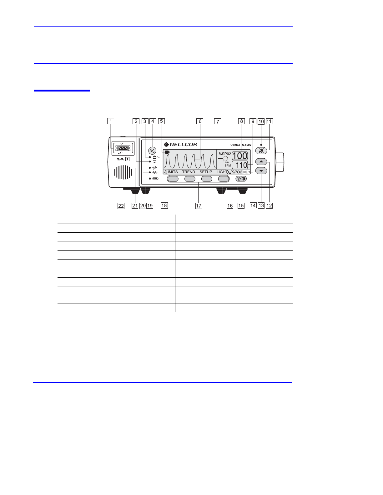
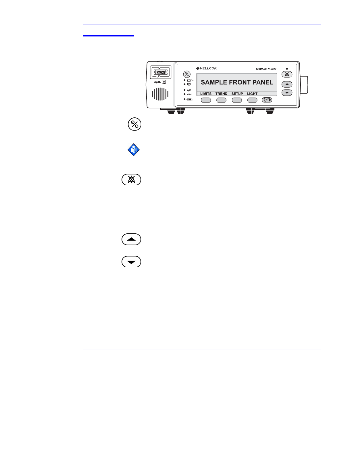
About the Front Panel
1. SpO2 OXIMAX Sensor Port, page 26.
2. Low Battery Indicator, page 17. 13. ADJUST DOWN Button, page 10.
3. AC Power Indicator, page 16. 14. Neonate Mode Indicator, page 18.
4. ON/STANDBY Button, page 10.
5. Battery Fuel Gauge Indicator, page 34. 16. Fast Response Mode Indicator, page 18.
6. Waveform Display, page 12. 17. Softkeys, page 11.
7. SatSeconds
8. %SpO
9. Pulse Rate Display, page 16. 20. Interference Indicator, page 17.
10. Alarm Silence Indicator, page 17. 21. Pulse Search Indicator, page 17.
11. ALARM SILENCE Button, page 10. 22. Monitor Speaker.
TM
Indicator, page 18.
2 Display, page 16. 19. Data In-Sensor Indicator, page 18.
12. ADJUST UP Button, page 10.
15. HELP/CONTRAST Button, page 11.
18. Menu Bar, page 11.
Figure 1: Front Panel Buttons and Symbols
N-600x Operator’s Manual 7
Page 16
Symbols, Controls, Displays and Indicators
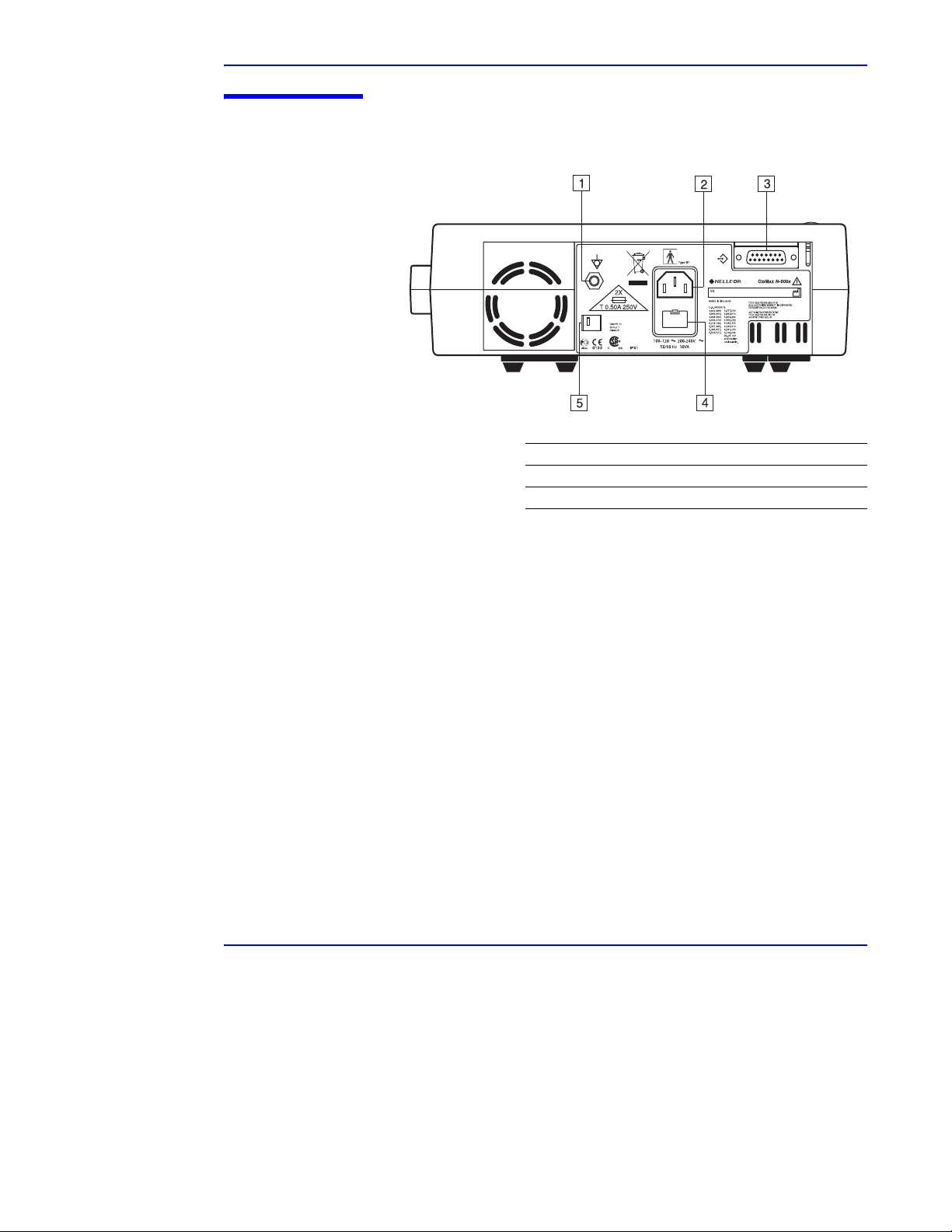
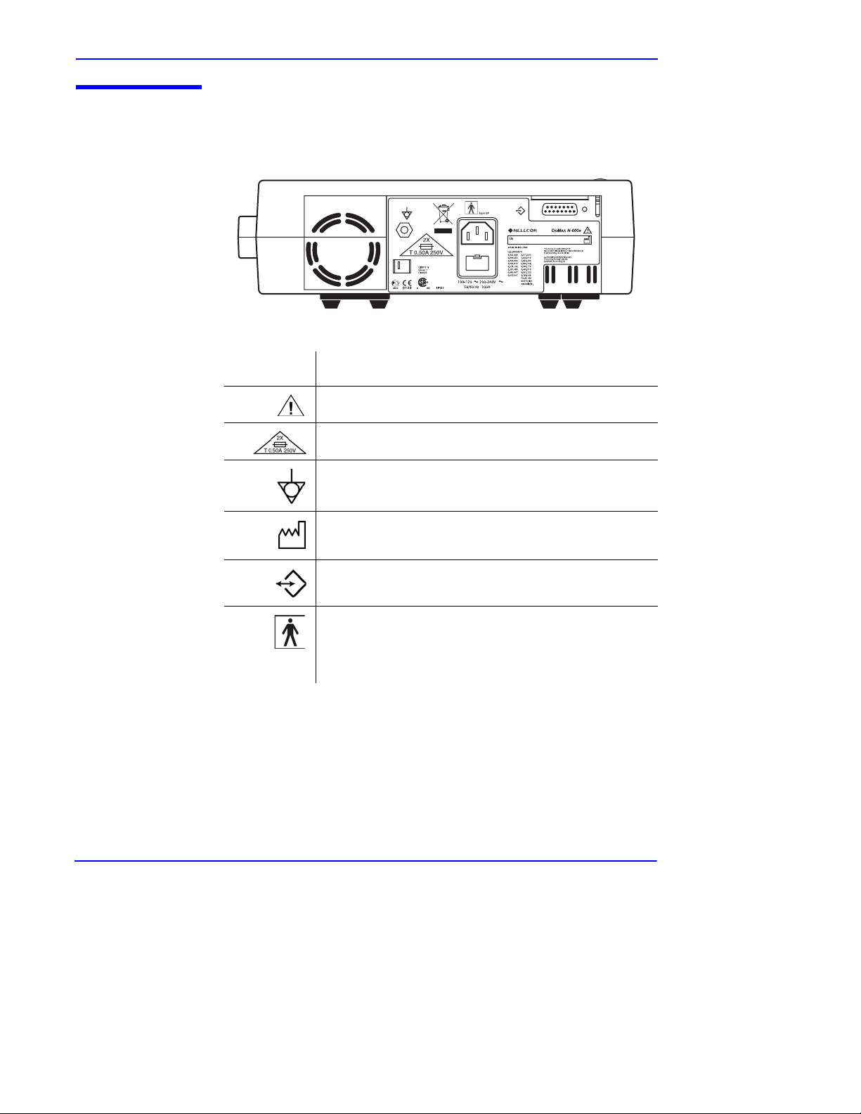
About the Rear Panel
1. Equipotential Terminal (Ground).
2. AC Power Connector, page 24.
3. Data Port Connector, page 112.
4. Fuse Holder.
5. Supply Voltage Selector Switch, page 24.
Figure 2: Rear Panel Components
8 N-600x Operator’s Manual
Page 17
About the Symbols
The symbols, located on the rear panel of the N-600x, are as follows.
Symbols, Controls, Displays and Indicators
Table 1: Symbols and Descriptions
Symbol
Description
See Instructions for Use
Fuse Replacement
Equipotential Terminal (ground)
Date of Manufacture
Data Interface
Type BF Applied Part - Not defibrillator proof
N-600x Operator’s Manual 9
Page 18
Symbols, Controls, Displays and Indicators
About the Controls
ON/STANDBY Button
Turns the monitor on and off.
Note: Pressing a button, except the ON/STANDBY button, should
result in either a valid or an invalid key tone (refer to Table 3). If the
key pressed fails to emit a tone, contact qualified service personnel.
ALARM SILENCE Button
Silences current alarms for the alarm silence duration period. When
an alarm has been silenced, pressing the button again reactivates, or
“unsilences” the alarm. It is also used to view and adjust alarm silence
duration and alarm volume. The ALARM SILENCE button clears
“SENSOR OFF,” “LOW BATTERY,” and “SENSOR
DISCONNECT” messages from the display.
ADJUST UP Button
Increases variable parameters of the monitor.
ADJUST DOWN Button
Decreases variable parameters in the monitor.
10 N-600x Operator’s Manual
Page 19
HELP/CONTRAST Button
Enables you to access the on-screen help and adjust the monitor
screen contrast.
Softkey Menu Bar
Displays the current functions for each of the four softkey
buttons.
About the Displays
Symbols, Controls, Displays and Indicators
• Pressing and releasing the HELP/CONTRAST button
launches the on-screen help.
• Pressing and holding the HELP/CONTRAST button
while simultaneously pressing the ADJUST UP and
ADJUST DOWN buttons lightens or darkens the display
screen.
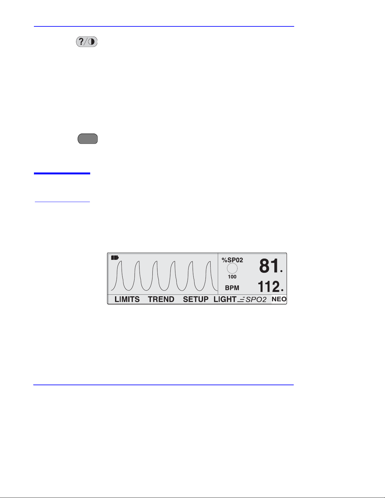
Pleth Display
The pleth display is user selectable. Refer to Selecting the Pleth View
on page 51.
N-600x Operator’s Manual 11
Page 20

Symbols, Controls, Displays and Indicators
The pleth display includes a “wiper bar” plethysmographic
waveform, menu bar, and current measured %SpO
SatSeconds are enabled, the pleth display includes the SatSeconds
indicator and SatSeconds setting. A decimal point after the %SpO
pulse rate indicates the respective limits have been changed from the
power on defaults (Overview on page 73). Plethysmographic
waveforms with peak to peak amplitudes less than ten PAUs are
associated.
Caution: Verify the movement of the blip bar or plethysmographic waveform or beating heart before accepting any
displayed data as a current measurement.
When the monitor is powered by the internal battery, the pleth display
includes a horizontal battery fuel gauge positioned in the upper left
corner which shows the remaining charge (operating hours) on the
battery. If a monitor reporting low battery is connected to an AC
power source, the battery fuel gauge displays the charging progress.
The battery fuel gauge is cleared from the display once the monitor
can provide at least 15 minutes of operating time.
2 and pulse rate. If
2 or
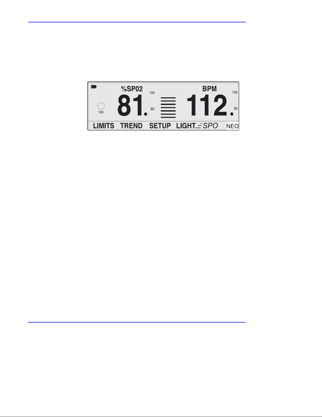
Blip Display
The blip display includes a pulse amplitude blip bar, current measured
%SpO
2 and pulse rate, and current upper and lower %SpO2 and pulse
rate limits. If SatSeconds are enabled, the blip display includes the
SatSeconds indicator and SatSeconds setting. Decimal points after the
%SpO
2 or pulse rate indicate that the respective limits have been
changed from the power-on defaults.
12 N-600x Operator’s Manual
Page 21
Symbols, Controls, Displays and Indicators
When the monitor is powered by internal battery, the blip display
includes a horizontal battery fuel gauge positioned in the upper left
corner that shows the remaining charge (operating hours) on battery.
If a monitor reporting a low battery is connected to AC power, the
battery fuel gauge shows the charging progress. The battery fuel
gauge is cleared from the display once the monitor can provide at
least 15 minutes of operating time on battery.
N-600x Operator’s Manual 13
Page 22
Symbols, Controls, Displays and Indicators
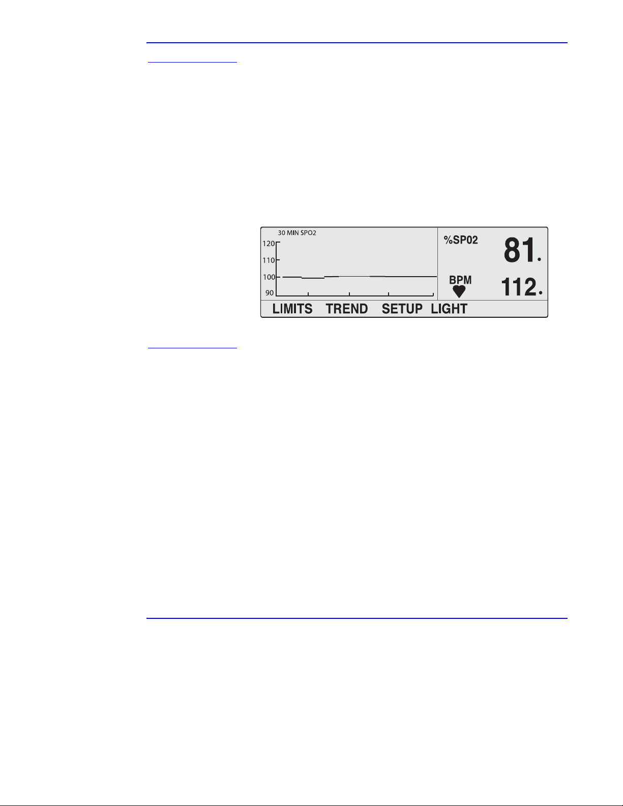
Real-Time Trend Display
The real-time trend display includes %SpO2 and/or pulse rate trend
data plots and current measured %SpO2 and pulse rates. The trend
data plots are automatically updated as each new trend point is
calculated, where the interval between calculations is based on the
display time scale selected. If SatSeconds is enabled, the real-time
trend display includes the SatSeconds indicator. Decimal points after
the displayed %SpO2 or pulse rate indicate that the respective limits
have been changed from the power-on defaults. Each time a pulse is
detected by the oximeter, a heart icon flashes.
SpO2 and Pulse Rates
There are various matrixes within the N-600x algorithm. Some of
these are used to assess the severity of conditions presented to the
N-600x in measuring SpO
individual matrices or combinations of these matrices are used to
drive the LED indicators on the N-600x front panel.
14 N-600x Operator’s Manual
2 and pulse rate on a patient. These
Page 23

Symbols, Controls, Displays and Indicators
The N-600x algorithm automatically extends the amount of data
required for measuring SpO
2 and pulse rate depending on the
measurement conditions. During normal measurement conditions the
averaging time is 6 to 7 seconds. During conditions such as those
caused by low perfusion, interference (e.g., external interference like
ambient light), or a combination of these, the N-600x algorithm
automatically extends the amount of data required beyond 7 seconds.
If the resulting dynamic averaging time exceeds 20 seconds, the pulse
search indicator is lit solid and SpO
2 and Pulse Rate will continue to
be updated every second. As these conditions extend, the amount of
data required continues to increase. If the dynamic averaging time
reaches 40 seconds, the pulse search indicator begins flashing, the
SpO
2 and pulse rate displays flash zeros indicating a loss-of-pulse
condition.
WARNING: Failure to cover the OXIMAX sensor site with opaque
material in high ambient light conditions may result in inaccurate
measurements.
N-600x Operator’s Manual 15
Page 24
Symbols, Controls, Displays and Indicators
About the Visual Indicators
Table 2: Visual Indicators
Indicator Description
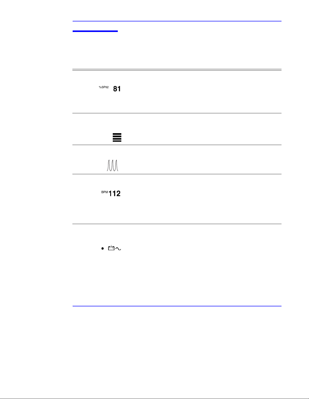
%SpO2 Display Shows the hemoglobin oxygen saturation level. The display value
flashes zeros during loss-of-pulse alarms and flashes the SpO
when the SpO
monitor continues to update the display. If alarm limits have been
changed from their power-on defaults, a decimal point (.) is
displayed after the SpO
2 is outside the alarm limits. During Pulse Search, the
2 value (81.).
2 value
Pulse Amplitude
Indicator (blip bar)
Indicates pulse beat and shows the relative (non-normalized) pulse
amplitude. As the detected pulse becomes stronger, more bars light
with each pulse. This indicator is available only in the blip view.
Plethysmographic
Waveform Display
Displays a non-normalized waveform in real-time sensor signals.
The relative pulsatile strength and quality of the incoming signals
can be observed.
Pulse Rate Display Displays the pulse rate in beats per minute. It flashes during
loss-of-pulse alarms and when the pulse rate is outside of the alarm
limits. During Pulse Search, the monitor continues to update the
display. Pulse rates outside of the pulse rate range of 20 to 250 bpm
are displayed as 0 and 250, respectively. If alarm limits have been
changed from their power-on defaults, a decimal point (.) is
displayed after the BPM value (112.).
AC Power
Indicator
Lights continuously when the N-600x is connected to an AC power
source. The indicator shows that the battery is charging. It is off
when the monitor is being powered by internal battery.
16 N-600x Operator’s Manual
Page 25
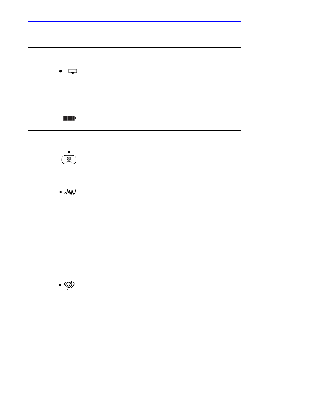
Table 2: Visual Indicators
Indicator Description
Symbols, Controls, Displays and Indicators
Low Battery
Indicator
Battery Fuel Gauge
Indicator
Alarm Silence
Indicator
Interference
Indicator
Lights continuously when 15 or fewer minutes of battery capacity
remain. Flashes when the battery capacity reaches a critically low
condition.
Displays the battery charge remaining on the monitor. The battery
fuel gauge consists of four bars, each corresponding to
approximately 1.5 hours of operating time. All four bars are lit
when the battery is fully charged. No bars are lit when a low battery
condition exists. See Battery Fuel Gauge Indicator on page 34.
Lights continuously when an audible alarm has been silenced. It
flashes when the alarm silence duration has been set to Off.
Lights whenever the N-600x algorithm detects the incoming signal
quality is degraded.
Note: Degradation can be caused by ambient light, electrical noise,
electro-surgical interference, patient activity, or other causes.
An intermittently lit Interference Indicator is common during
patient monitoring, and indicates the N-600x algorithm is
dynamically adjusting the amount of data required for measuring
2 and Pulse Rate. When lit continuously, the N-600x algorithm
SpO
has extended the amount of data required for measuring SpO
2 and
Pulse Rate and consequently fidelity in tracking rapid changes in
these values may be reduced.
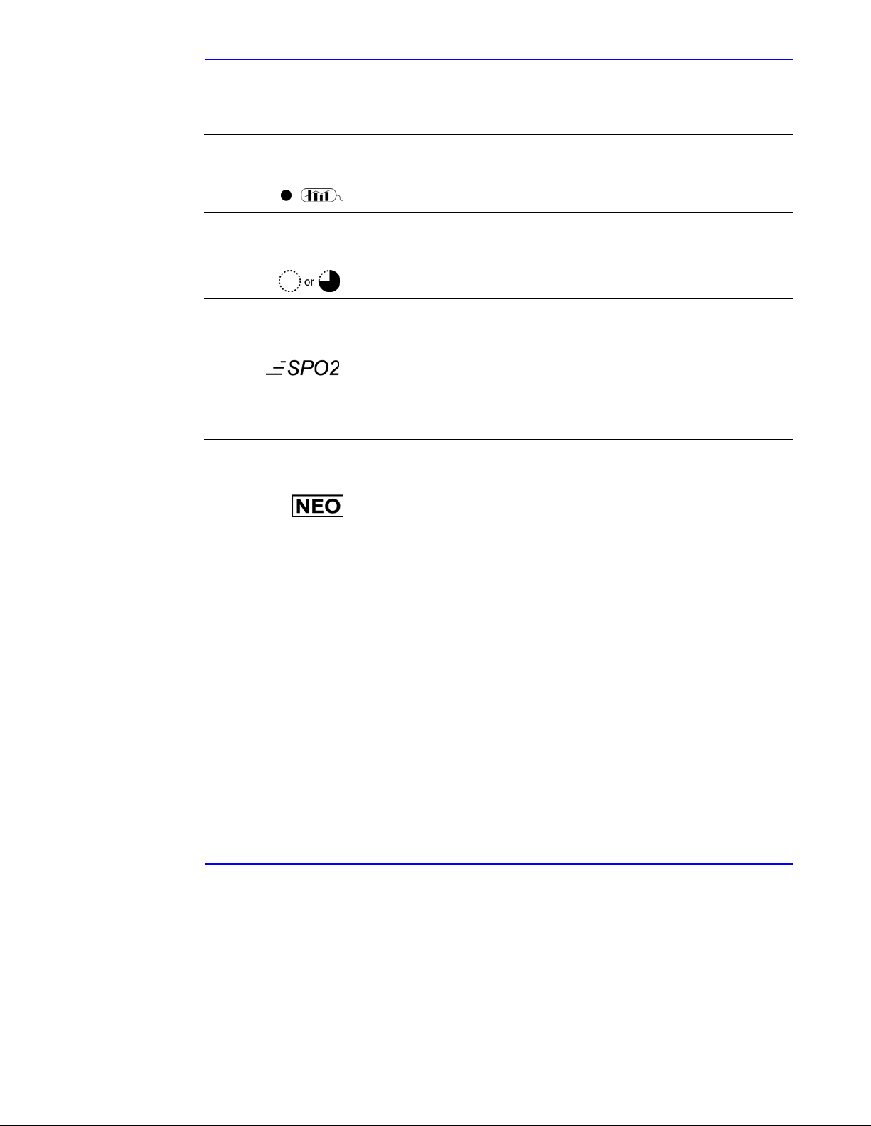
Pulse Search
Indicator
Lights continuously prior to initial acquisition of a pulse signal and
during prolonged and challenging monitoring conditions. The pulse
search indicator flashes during a loss-of-pulse signal.
N-600x Operator’s Manual 17
Page 26
Symbols, Controls, Displays and Indicators
Table 2: Visual Indicators
Indicator Description
Data In-Sensor
Indicator
SatSeconds
Indicator
Fast Response
Mode Indicator
Neonate Alarm
Limits Indicator
Lights to indicate that the attached OXIMAX sensor contains a patient
sensor event record. The sensor event record information may be
viewed or printed.
Fills in clockwise as the SatSeconds alarm management system
detects a %SpO
counterclockwise direction when %SpO
2 reading outside of the limit setting. Empties in
2 reading is within limits.
When the indicator is full, a medium priority alarm sounds.
Determines the response time (2 to 4 seconds in fast mode and 5 to
7 seconds in normal mode) applied by the O
calculation of SpO
2. The OXIMAX algorithm’s calculation of pulse
XIMAX algorithm in its
rate is unaffected by the response mode setting. The trending
interval (2 seconds or 4 seconds) updated automatically by the
monitor to roughly correspond with the SpO
2 calculation response
time.
Displays when the alarm limits are set to neonate. No symbol
displays when the monitor is set to adult limits.
18 N-600x Operator’s Manual
Page 27

About the Audible Indicators
Table 3: Audible Indicators
Function Description
Symbols, Controls, Displays and Indicators
Alarm Silence
Reminder
Confirmation Tone Three beeps sound to indicate default settings
Invalid Button Press
Valid Button Press
High Priority Alarm
Medium Priority
Alarm
Three beeps sound approximately every three
minutes when alarms are silenced with the
alarm silence duration set to OFF and the alarm
silence reminder function is enabled.
have been saved or reset to factory defaults or
trend data has been deleted.
Short, low
been pressed that is inappropriate for the
current state of the monitor.
Short, medium
appropriate button has been pressed.
High
loss
Note: If a High Priority Alarm is not silenced
within 30 seconds by pressing the ALARM
SILENCE Key, the monitor increases the
urgency level of the audible alarm signal by
alternating a piezo tone with the primary alarm
tone. See Piezo Tone on page 20.
Medium
-pitched tone indicating a button has
-pitched tone indicating an
-pitched, fast-pulsing tone indicating
-of-pulse.
-pitched, pulsing tone indicating an
SpO2 or pulse rate limit violation.
Note: If a Medium Priority Alarm is not
silenced within 2 minutes by pressing the
ALARM SILENCE Key, the monitor increases
the urgency level of the audible alarm signal by
alternating a piezo tone with the primary alarm
tone. See Piezo Tone on page 20.
N-600x Operator’s Manual 19
Page 28

Symbols, Controls, Displays and Indicators
Table 3: Audible Indicators
Function Description
Low Priority Alarm
-pitched, slow-pulsing tone indicating an
Low
OXIMAX sensor disconnect, low battery, or
monitor failure.
Note: If a Low Priority Alarm is not silenced
within 2 minutes by pressing the ALARM
SILENCE Key, the monitor increases the
urgency level of the audible alarm signal by
alternating a piezo tone with the primary alarm
tone. See Piezo Tone on page 20.
Piezo Tone A high-pitched piezo tone is sounded if there is
no user response to an audible alarm, or if the
monitor detects a failure of the primary
speaker. See High, Medium, and Low Priority
Alarms in Ta ble 3.
Power
-On Self-Test
Pass
Pulse Beep Single beep sounds for each detected pulse.
Volume Setting Tone Continuous tone used when adjusting the alarm
One-second tone indicating the monitor has
been turned on and has successfully completed
the power
The pitch of the pulse beep signal changes with
a point
level.
volume.
-on self-test.
-by-point rise or fall in the saturation
20 N-600x Operator’s Manual
Page 29
Setting Up the Monitor
WARNING: To ensure patient safety, do not place the pulse
oximeter in any position that might cause it to fall on the patient.
WARNING: As with all medical equipment, carefully route
patient cabling to reduce the possibility of patient entanglement
or strangulation.
WARNING: Ensure that the speaker is clear of any obstruction.
Failure to do so could result in an inaudible alarm tone.
WARNING: Disconnect the N-600x and Nellcor OXIMAX sensor
from the patient during magnetic resonance imaging (MRI)
scanning. Objects containing metal can become dangerous
projectiles when subjected to the strong magnetic fields created
by MRI equipment. Also, induced currents could potentially
cause burns.
Setting Up the Monitor
WARNING: To ensure accurate performance and prevent device
failure, do not subject the N-600x to extreme moistur e, such as
direct exposure to rain. Such exposure may cause inaccurate
performance or device failure.
WARNING: Do not use an N-600x pulse oximeter, OXIMAX sensor,
cables, or connectors that appear damaged.
N-600x Operator’s Manual 21
Page 30
Setting Up the Monitor
WARNING: Do not lift the pulse oximeter by the pulse oximetry
cable or power cord because the cable or cord could disconnect
from the pulse oximeter, causing the pulse oximeter to drop on
the patient.
WARNING: The N-600x is not defibrillator-proof. However, it
may remain attached to the patient during defibrillation or while
an electrosurgical unit is in use, but the readings may be
inaccurate during the defibrillation and shortly thereafter.
WARNING: In the USA, do not connect the pulse oximeter to an
electrical outlet controlled by a wall switch, because the pulse
oximeter may be accidentally turned off.
WARNING: Use only the Nellcor pulse oximetry cable DOC-10
with the N-600x pulse oximeter. Use of another pulse oximetry
cable will have an adverse effect on performance. Do not attach
any cable that is intended for computer use to the O
XIMAX sensor
port. Do not connect any device other than a Nellcor -approved
OXIMAX sensor to the OXIMAX sensor connector.
WARNING: The N-600x should not be used adjacent to or
stacked with other equipment. If adjacent or stacked use is
necessary, the N-600x should be observed to verify normal
operation in the configuration it is to be used.
Note: The monitor incorporates watchdog timers which reset the
monitor in the event of software errors.
22 N-600x Operator’s Manual
Page 31

List of Components
Setting Up the Monitor
Quantity Item
1
1 Nellcor O
1
1
1 Power Cord (applicable to country of sale)
2
1 Quick Guide
-600x Pulse Oximeter
N
XIMAX Sensor or Assortment Pack
DOC
-10 Pulse Oximetry Cable
N
-600x Operator’s Manual (applicable to
country of sale) and/or compact disc
Fuses, 0.5 A, 250 volts, slow
(5 x 20 mm)
-blow, IEC
N-600x Operator’s Manual 23
Page 32

Setting Up the Monitor
Connecting to an AC Power Source
WARNING: In the USA, do not connect the pulse oximeter to an
electrical outlet controlled by a wall switch, because the pulse
oximeter may be accidentally turned off.
Caution: The Supply Voltage Selector switch must be set to the
correct voltage (115 or 230) to avoid equipment damage and
ensure battery charging.
Caution: Use only the hospital-grade power cord provided by
Nellcor.
1. Set the Supply Voltage Selector switch to the applicable voltage.
2. Plug the female connector end of the power cord into the power
connector on the rear of the monitor.
3. Plug the male connector of the power cord into a properly
grounded AC outlet.
24 N-600x Operator’s Manual
Page 33

Setting Up the Monitor
Caution: Ensure the pulse oximeter is properly grounded when
operating on AC power. If you are uncertain whether the AC
outlet is properly grounded, disconnect the pulse oximeter from
the outlet and use the battery power. Contact a qualified
electrician to examine the outlet for ground connections.
4. Verify the monitor’s AC power indicator is lit.
Note: If the AC power indicator is not lit, check the:
• power cord
• supply voltage selector switch
•user-accessible fuses
• AC power outlet
Note: The monitor can be operated with a depleted battery when
connected to an AC power outlet. A warning message displays and
must be cleared by pressing the ALARM SILENCE button before
the monitor can be used for patient monitoring.
N-600x Operator’s Manual 25
Page 34

Setting Up the Monitor
Connecting an OXIMAX Sensor
The OXIMAX sensor type is shown at the bottom of the display when
XIMAX sensor is connected to the N-600x or when the monitor
an O
completes POST with an O
Note: Sensor LED light emissions fall within Class 1 level, according
to IEC 60825-1:2001.
XIMAX sensor attached.
Caution: Use only Nellcor-approved O
XIMAX sensors and pulse
oximetry cables.
Note:Physiological conditions, medical procedures, or external
agents that may interfere with the monitor’s ability to detect and
display measurements include dysfunctional hemoglobin, arterial
dyes, low perfusion, dark pigment, and externally applied coloring
agents, such as nail polish, dye, or pigmented cream.
1. Firmly connect a DOC-10 pulse oximetry cable to the SpO
XIMAX Sensor Port of the monitor.
O
2
2. Connect a Nellcor O
XIMAX SpO2 sensor to the opposite end of the
DOC-10 pulse oximetry cable.
26 N-600x Operator’s Manual
Page 35

Operating the Battery
WARNING: Dispose of battery in accordance with local
requirements and regulations.
Operating on Battery Power
The N-600x monitor has an internal battery that can be used to power
the monitor during transport or when AC power is not available. A
new, fully charged battery provides at least 7 hours of monitoring
time under the following conditions:
• No audible alarms sound
• No analog or serial output devices are attached to the
N-600x
Operating the Battery
• Default display brightness setting
The monitor cannot be used when the battery is depleted unless the
monitor is connected to an AC power source. A warning message
displays and must be cleared by pressing the ALARM SILENCE
button before the monitor can be used for patient monitoring.
The pleth and blip displays include a battery fuel gauge indicator that
shows the remaining charge (operating hours). When the monitor is
fully charged, all four bars are lit on the indicator.
Caution: If the N-600x monitor is stored for a period of three
months or longer, notify service personnel to place the monitor in
"Shelf-mode" prior to storage. The monitor can be placed in
"Shelf-mode" by qualified service personnel using the procedures
indicated in the N-600x Service Manual. Recharge the battery
when it has not been charged for three or more months.
N-600x Operator’s Manual 27
Page 36

Operating the Battery
Caution: Replace the battery if fewer than four bars are lit after
fully charging the battery. To charge a low or fully depleted
battery, connect the monitor to AC power outlet. A full charge of
a fully depleted battery takes 8 hours to charge while the monitor
is turned off. A full charge of a fully depleted battery takes 12
hours while the monitor is in the normal operating mode.
Caution: If the monitor is operated on an AC power source with a
depleted battery and the AC power is subsequently lost, the
monitor will shut down immediately.
When all of the following conditions are present for 15 minutes, the
N-600x automatically shuts down:
• Monitor is running on battery power
• No buttons have been pressed
• No pulse has been detected (for example, when a patient
is not connected to the O
XIMAX sensor or the OXIMAX
sensor is disconnected from the monitor)
• No alarms are present (other than low battery or a
non-correctable error)
Note:Whenever the monitor is connected to AC power source, the
battery is being charged. We recommend the monitor remain
connected to an AC power source when not in use. This ensures a
fully-charged battery when the monitor is needed.
28 N-600x Operator’s Manual
Page 37

Low Battery Indicator
The Low Battery Indicator lights and a low priority alarm begins to
sound when approximately 15 minutes of monitoring time is
available on the existing battery charge. Refer to Table 4 for a
description of the low and critical battery conditions.
A low battery audible alarm can be cancelled by pressing the
ALARM SILENCE button. The low battery indicator and display
screen message continues to display. Connecting the monitor to an
AC power source silences the audible alarm, but the low battery
indicator remains lit as long as the battery is in the low voltage
condition. After the 15-minute period of low battery condition, a high
priority alarm sounds for about 10 seconds before the monitor shuts
off.
If the monitor backlight is turned off during a low battery condition,
the backlight cannot be turned back on.
Operating the Battery
Nellcor recommends that a qualified service personnel replace the
internal battery every 24 months. Replaced batteries should be
disposed of in accordance with local ordinances.
Caution: The pulse oximeter default settings will return to
factory default setting if the battery becomes fully discharged or
is replaced. Qualified service personnel will have to reset the
institutional defaults, following the instructions in the
N-600x Service Manual.
Note: If the AC voltage selector switch on the monitor rear panel
does not match your AC voltage source, the monitor may run on
battery power, even though it is connected to an AC power source,
which eventually results in a low priority alarm and a lighted low
battery indicator. Ensure that the switch setting matches your AC
voltage.
Note: As the battery is used and recharged over time, the amount of
time between the onset of the low battery alarm and the instrument
shut-off may become shorter.
N-600x Operator’s Manual 29
Page 38

Operating the Battery
Description of Low and Critical Battery Conditions
Table 4: Low and Critical Battery Conditions
State
1No No Yes
2No No No
Critical
Battery
Low
Battery
AC
Power
Operation
2-normal
SpO
AC/Battery charge LED
LOW BATTERY LED
LOW BATTERY
message
Audible alarm
Error code
Effect of ALARM
SILENCE key
Shutdown
SpO
AC/Battery charge LED
LOW BATTERY LED
LOW BATTERY
message
-off
-off
-none
-normal
-N/A
2-normal
-off
-on
-off
-off
-off
Audible alarm
Error code
Effect of ALARM
SILENCE key
Shutdown
30 N-600x Operator’s Manual
-off
-none
-normal
- N/A
Page 39

Operating the Battery
State
3No Yes No
4No Yes Yes
Critical
Battery
Low
Battery
AC
Power
Operation
2-normal
SpO
AC/Battery charge LED
LOW BATTERY LED
LOW BATTERY
message
Audible alarm
Error code
Effect of ALARM
SILENCE key
silences audio alarm, second
press cancels LOW
BATTERY message (LED)
stays on until Low Battery
Condition is corrected.
Shutdown
SpO
-on
-low priority
-logged
-First press
-Imminent
2-normal
-off
-on
AC/Battery charge LED
LOW BATTERY LED
LOW BATTERY
message
Audible alarm
Error code
Effect of ALARM
SILENCE key
stays on)
Shutdown
-off
-off
-logged
-N/A (LED
-N/A
-on
-on
Note: Connecting AC
functions the same as
ALARM SILENCE key
in state 3.
N-600x Operator’s Manual 31
Page 40

Operating the Battery
State
Critical
Battery
Low
Battery
AC
Power
5 Not used
6Yes Yes No
Operation
2-not displayed
SpO
AC/Battery charge LED
LOW BATTERY LED
(flashing)
LOW BATTERY
message
Audible alarm
Error code
-on
-high priority
-displayed and
logged
Effect of ALARM
SILENCE key
Shutdown
-none
-after 10 seconds
-off
-on
32 N-600x Operator’s Manual
Page 41

Operating the Battery
State
Critical
Battery
Low
Battery
AC
Power
Operation
7 Yes Yes Yes SpO2 - displayed.
AC/Battery Charge LED on
LOW BATTERY LED-on
(flashing)
LOW BATTERY message on
The Battery Fuel Gauge
Indicator shows a fully
depleted battery (no bars
lit).
Warning message in the
pleth window: UNIT WILL
SHUT DOWN IF AC
POWER LOST
Audio alarm - low priority
Error code - logged
Affect of Silence key - One
press silences the audible
alarm. Pressing the Affect
Silence key twice cancels
the LOW BATTERY
message, removes the
warning message and
restores default Pleth (or
Blip) display (LED
continues to FLASH until
Low Battery condition is
not true, Battery Fuel Gauge
Indicator shows charging
progress)
Shutdown - N/A
N-600x Operator’s Manual 33
Page 42

Operating the Battery
Battery Fuel Gauge Indicator
The N-600x has a battery fuel gauge indicator which displays the
battery power remaining on the monitor . The indicator appears on the
the pleth and blip display screens. When the monitor is fully charged,
all four bars are lit on the battery fuel gauge indicator. The battery
fuel gauge indicator capacities are described below.
Table 5: Battery Fuel Gauge Indicator Levels
Level Description
Indicates 100% battery capacity remaining.
Indicates 75% battery capacity remaining.
Indicates 50% battery capacity remaining.
Indicates 25% battery capacity remaining.
Indicates 0% battery capacity remaining.
Note: The levels in Table 5 are based on a brand new battery. As a
battery is used and recharged over time, it may provide only 75% of
the capacity of brand new battery. For example, a battery that is twoyears old may provide only 75% (3 bars) of the capacity of a new
battery.
Caution: If the battery is fully depleted, and the AC power is lost,
the monitor will shut down.
34 N-600x Operator’s Manual
Page 43

Using the Monitor
Overview
This section describes menu navigation, power on/off and display
options, parameter ranges, O
configuring default settings suitable for your environment.
Menu Description
The N-600x is outlined below. You can choose the type of trend data
to view by selecting either Monitor trend or Sensor trend data in the
Trend menu. Sen sor sub-menu choices dif fer depending o n what typ e
of in-sensor data is stored in the sensor chip, such as, event or loop.
Using the Monitor
XIMAX sensor attachments, and
The menu structure includes BACK softkey options that enable you
to move back to the previous menu level without exiting the Trend
menu entirely. Trend data must be compiled on entry/reentry to the
Trends menu. When the softkeys are available, both BACK and EXIT
options are available. The BACK softkey goes to the previous level
and the EXIT softkey goes to the main menu. If only one space is
available the BACK softkey is included, this may require going back
one or two levels to get to an EXIT softkey.
The BACK and EXIT softkeys are positioned on the right-most
softkeys, respectively. The below menu structure identifies:
• BOLDFACE TYPE — softkey title as displayed on the
monitor
• Underlined Text
• Italicized Text — the destination of the BACK and EXIT
softkeys
N-600x Operator’s Manual 35
— description of the softkey menu item
Page 44

Using the Monitor
Menu Structure
Main Menu
LIMITS (Limits Menu)
- SELECT
- NEO
- ADULT
EXIT (to Main menu)
TREND (Trend Menu)
- MON (Monitor Menu)
--VIEW (Monitor Trend View Menu)
---DUAL
---SPO2
---PULSE
---NEXT (History/Amplitude Menu)
----HIST (Delete/Print2 Menu)
-----DELETE (Delete Trends)
------“DELETE TRENDS”
-------YES (return to Main menu)
-------NO (back to Delete/Print menu)
-----PRINT
-----BACK (back to Hist/Amp menu)
-----EXIT (to Main menu)
----AMP (Amplitude Menu)
-----BACK (back to Hist/Amp menu)
-----EXIT (to Main menu)
----BACK (back to Monitor Trend View menu)
----EXIT (to Main menu)
--ZOOM (Monitor Trend Zoo m Menu)
---TIME (Cycle through 48h, 36h, 24h, 12h, 8h, 4h, 2h,
1h, 30m, 15m, 40s, 20s for current view)
---SCALE (Cycle through ±5, ±10, ±15, ±20, ±25, ±30,
±35, ±40 and ±50 (units of BPM or %SpO
depending on the data displayed) of the max and
min. values under the cursor, default to 10 to 100
for SAT trend graph and 5-250 for Pulse trend
graph if there is no data point under the cursor for
current view)
---AUTO (Based on all of the graphed trend data:
maximum value, rounded up to nearest multiple of
10, minimum value, rounded down to nearest
multiple of 10 minus 10)
---BACK (back to Monitor menu)
2,
36 N-600x Operator’s Manual
Page 45

Using the Monitor
Menu Structure
(continued...)
--NEXT (Delete/Print1 Menu)
---DELETE
----“DELETE TRENDS?”
-----YES (to Main menu)
-----NO (back to Delete/Print1 menu)
---PRINT
---BACK (back to Monitor menu)
---EXIT (to Main menu)
--BACK (back to Trend menu)
- SENSOR (Sensor/Event Menu)
(if Event data is in the sensor, the following menu, the Screen will
remain in the appropriate state until the next
menu selection is made)
--GRAPH (Graph Menu)
chronological order; up/down also scroll through
events in order)
---< (show previous graph, only available when there is a
previous graph)
---> (show next graph, only available when there is a next
graph)
---PRINT
---BACK (back to Sensor menu)
--TABLE (Table Menu)
---^ (show previous table, only available when there is a
previous graph; bottom/top line repeats in new
table)
---v (show next table, only available when there is a next
graph; bottom/top line repeats in new table)
---PRINT
---BACK (back to Sensor menu)
--BACK (back to Trend menu)
---EXIT (to Main menu)
(Sensor/Loop Menu)
the following will be displayed)
--VIEW (Sensor Trend View Menu)
---DUAL (shows SPO2+BPM)
---SPO2
---PULSE
--ZOOM (cycle through 2h, 1h, 30m, and 15m for current
view)
(display events #1-N, in inverse
(If continuous-Loop data is in the sensor,
N-600x Operator’s Manual 37
Page 46

Using the Monitor
Menu Structure
(continued...)
--PRINT
--BACK (to Trend menu)
- EXIT (to Main menu)
SETUP (Setup Monitor Menu)
- VIEW (Setup View Menu)
--PLETH
--BLIP
- TREND
---VIEW (RT
Trend View Menu)
----DUAL
----SPO2
----PULSE
----BACK
---ZOOM (RT
Trend View Menu)
----TIME
----SCALE
----AUTO
----BACK
--BACK (back to Setup menu)
--EXIT (to Main menu)
---SENSOR (Setup Sensor Menu)
--DATA (On-screen options for SENSOR-R (Write-once
Sensor) sensor are: “SPO2, SPO2+BPM,
DEFAULT.” On-screen options for SENSOR-RW
(rewritable sensor) are: “SPO2, SPO2+BPM,
DEFAULT.” SELECT toggles SENSOR-R or
SENSOR-RW sensor type; up/down keys scroll
through options in order.) The SENSOR-R feature
supports all of the current O
XIMAX sensors.
---SELECT
---BACK (back to Setup Sensor menu)
---EXIT (to Main menu)
--MSG (Sensor Set Message Menu)
---BACK (back to Setup Sensor menu)
---EXIT (to Main menu)
- NEXT (Clock/Language Menu)
--CLOCK (Clock Menu)
---SET (Clock Set Menu)
----SELECT (press select to toggle through hours,
minutes, seconds, month, day, year; use up/down
buttons to set each selection)
38 N-600x Operator’s Manual
Page 47

Using the Monitor
Menu Structure
(continued...)
----BACK (back to Clock/Language menu)
----EXIT (to Main menu)
---BACK (back to Clock/Language menu)
---EXIT (to Main menu)
--LANG (Language Setup Menu)
toggle though languages)
---BACK (back to Clock/Language menu)
--NEXT (Communication/Nurse Call Menu)
---COMM (Communication Port Configuration Menu)
----SELECT
----BACK (back to Communication/Language menu)
----EXIT (to Main menu)
---NCALL Nurse Call Menu)
----NORM +
----NORM -
----BACK (back to Communication/Nurse Call menu)
----EXIT (to Main menu)
---NEXT (Analog/Mode Menu)
----ANALOG (Analog Voltag e Select Menu)
-----0 VOLT
-----1 VOLT
-----STEP
-----BACK (back to Analog/Mode menu)
----MODE (Mode Menu)
-----BACK (back to Analog/Mode menu)
-----EXIT (to Main menu)
----BACK (back to Communication/Nurse Call menu)
----EXIT (to Main menu)
---BACK (back to Clock/Language menu)
--BACK (back to Setup menu)
- EXIT (to Main menu)
LIGHT (Light Menu)
- OFF (Turns display backlight off)
- EXIT (to Main menu)
(use up/down buttons to
N-600x Operator’s Manual 39
Page 48

Using the Monitor
Parameter Ranges
The parameters of the N-600x monitor are preset to factory default
settings. See Factory Default Settings on page 167. The factory
default parameters may be changed to institutional default parameters
by following the procedures in the N-600x Service Manual.
Table 6 lists the parameters, ranges available, and the factory default
setting. The parameters may be set on an individual basis, by the
clinician, and these settings remain in effect until the monitor is
turned off.
Table 6: Parameter Ranges
Parameter
%SpO
2
Upper Alarm
Limit
2
%SpO
Lower Alarm
Limit
Pulse Rate
Upper Alarm
Limit
Pulse Rate
Lower Alarm
Limit
Alarm
Silence
Duration
Alarm
Volu m e
Alarms
Ranges/
Selections
Lower Alarm
Limit plus 1 to
100%
20% to Upper
Alarm Limit
minus 1
Lower Alarm
Limit plus 1 to
250 bpm
30 bpm to Upper
Alarm Limit
minus 1
Alarms 30, 60,
90, 120 seconds
1 to 10 7 7
Allow Off
Yes/No
-
Factory
Adult Defaults
100% 95%
85% 85%
170 bpm 190 bpm
40 bpm 90 bpm
60 60
No
Factory
Neonate
Defaults
No
Off Reminder Yes/No
40 N-600x Operator’s Manual
Yes
Yes
Page 49

Table 6: Parameter Ranges
Using the Monitor
Parameter
Backlight
Brightness
Data Port
Baud Rate
Data Port
Mode
Default
Display
Format
Display
Contrast
Language English, Danish,
Ranges/
Selections
0 to 10
2400, 9600,
19200
ASCII, GRAPH,
OXINET,
CLINICAL,
PHILIPS,
SPACELBS,
MARQ (GE
Marquette),
DATEX (DatexOhmeda)
Pleth, Blip
Real-Time T rend
Low to high Medium Medium
Dutch, Finnish,
French, German,
Norwegian,
Portuguese,
Spanish, Italian,
Swedish
Factory
Adult Defaults
9600 9600
ASCII ASCII
Pleth Pleth
English English
Factory
Neonate
Defaults
Limits Adult, Neonate A dult Neonate
On AC
Power
On Battery
Power
Pulse Beep
Vol ume
Pulse Rate
Lower Alarm
Limit
N-600x Operator’s Manual 41
0 to 10 4 4
30 bpm to Upper
Alarm Limit
minus 1
10 10
88
40 bpm 90 bpm
Page 50

Using the Monitor
Table 6: Parameter Ranges
Parameter
Pulse Rate
Upper Alarm
Limit
Real-Time
Trend
Ranges/
Selections
Lower Alarm
Limit plus 1 to
250 bpm
Saturation, Dual,
Pulse Rate
Display
Real-Time
Trend Scale
48, 36, 24, 12, 8,
4, 2, 1 hours, 30
minutes
Response
Normal or Fast Normal Normal
Mode
-232 Level
RS
Nurse Call
Normally High,
Normally Low
Polarity
SatSeconds Off, 10, 25, 50,
100
Allow
Yes/No Yes Yes
SatSeconds
Factory
Adult Defaults
Factory
Neonate
Defaults
170 bpm 190 bpm
Saturation Saturation
30 minutes 30 minutes
Normally Low Normally Low
Off Off
Sensor Event
Date Format
(SENSOR-R
and
SpO
2,
SpO
2+Pulse Rate,
Default (default is
factory default)
Default Default
SENSOR-R
W
Sensor
Yes/No Yes Yes
Messages
Enabled
Trend
Display
Dual, %SpO
2,
Pulse, Histogram,
%SpO2 %SpO2
Amplitude
Trend Scale 48, 36, 24, 12, 8,
2 hours 2 hours
4, 2, 1 hours, 30,
15 minutes, 40,
20 seconds
42 N-600x Operator’s Manual
Page 51

Turning On the Monitor
Before using the monitor in a clinical setting, verify the monitor is
safe and working properly. Proper working condition is verified each
time the N-600x is turned on as described in the following procedure.
Caution: If any indicator or display element does not light when
the pulse oximeter is turned on, do not use the pulse oximeter.
Instead, contact qualified service personnel, your local Nellcor
representative, or Nellcor’s Technical Services Department.
Note: Physiological conditions, medical procedures, or external
agents that may interfere with the monitor’s ability to detect and
display measurements, include dysfunctional hemoglobin, arterial
dyes, low perfusion, dark pigment, and externally applied coloring
agents such as nail polish, dye, or pigmented cream.
Note: The monitor automatically launches the Power-On Self-Test
(POST), which tests the monitor circuitry and functions.
Using the Monitor
Caution: During POST (immediately after power-up), confirm
that all indicators light, all display segments turn on, and the
pulse oximeter speaker sounds a sequence of three ascending
tones. After the POST process complete, verify that a single onesecond tone sounds.
1. Turn on the monitor by pressing the ON/STANDBY button.
2. Ensure all of the front panel indicators illuminate.
N-600x Operator’s Manual 43
Page 52

Using the Monitor
3. Once the display test portion of POST completes, the software
version displays for approximately five seconds and a sequence
of three ascending tones sound.
Note:The software version shown above is only a sample. Check your
monitor for the current software version installed.
The software version is often needed when calling Nellcor’s
Technical Services Department or your local Nellcor representative
for technical assistance. Record the software version number and
have it available prior to contacting technical assistance.
4. If the monitor detects an internal problem during the POST
process, an error tone sounds and the monitor displays an error
code (EEE) and the corresponding number (see Troubleshooting
on page 139).
5. Upon successful completion of the POST, the monitor sounds a
one-second tone indicating the monitor has passed the test.
44 N-600x Operator’s Manual
Page 53

WARNING: If you do not hear the POST pass tone, do not use
the pulse oximeter.
WARNING: Ensure the speaker is clear of any obstructions.
Failure to do so could result in an inaudible alarm tone.
Note:In addition to serving as the POST pass verification, the POST
pass tone also functions as an audible confirmation that the speaker is
performing properly. If the speaker does not function, the alarm
warning sounds cannot be heard.
OXIMAX Sensor Attached
WARNING: Do not use any other cables to extend the length of
the DOC-10 Pulse Oximetry Cable. Increasing the length of the
DOC-10 cable will degrade signal quality and may lead to
inaccurate measurements.
Using the Monitor
When an O
XIMAX sensor is connected to the monitor, a “SENSOR
TYPE: . . .” message is displayed 4 to 6 seconds at the bottom of the
monitor display. The message identifies the type (model) of O
XIMAX
sensor connected to the monitor. The type is used to determine the
action messages in the O
display is the first message displayed when an O
XIMAX sensor message(s) function. This
XIMAX sensor is
connected to the monitor.
N-600x Operator’s Manual 45
Page 54

Using the Monitor
For a sensor containing data, the message identifies the sensor data
type. For a blank sensor, the message identifies the monitor’s current
data type setting used to write data to the sensor. The data type
settings are SpO
2 and SPO2+BPM.
Note:The type of data recorded is only displayed when data is present
in the O
XIMAX sensor.
The monitor displays zeros in the %SpO
2 and Pulse Rate displays
while the N-600x is searching for a valid pulse. For optimal
performance, allow the monitor to search and lock onto a pulse for
approximately 5 to 10 seconds.
When a valid pulse is detected, the monitor enters the Monitoring
Mode and displays patient parameters.
46 N-600x Operator’s Manual
Page 55

Using the Monitor
Notice the movement of the blip bar or plethysmographic waveform
or beating heart indicating the monitor is displaying real-time data.
Listen for the pulse beep tone. If the pulse beep tone does not sound
with each pulse, it is an indication the pulse beep volume is set to
zero, the speaker is malfunctioning, or the signal is corrupt.
N-600x Operator’s Manual 47
Page 56

Using the Monitor
When an OXIMAX sensor is attached to the monitor and applied to a
patient, the monitor may lose a pulse signal. If a pulse signal is lost,
an alarm sounds and a poor signal condition message displays on the
monitor screen. At this point, the monitor displays [
--- / ---]
(3 dashes / 3 dashes) and remains in the Pulse Search Mode for five
seconds before displaying the poor signal condition screen. The poor
signal condition screen is part of the N-600x's Sensor Messages
feature. For more information about O
XIMAX Sensor Messages, refer
OXIMAX Sensor Messages on page 69.
48 N-600x Operator’s Manual
Page 57

No OXIMAX Sensor Attached
Upon successful completion of the POST process, the monitor sounds
a one-second tone indicating that the monitor has passed the POST.
or
Using the Monitor
The monitor displays dashes [ - - - ] and the Pulse Search indicator is
not lit, indicating the monitor failed to detect an O
N-600x Operator’s Manual 49
XIMAX sensor.
Page 58

Using the Monitor
Turning the Backlight On or Off
You can turn off the backlight by pressing the LIGHT softkey and
then pressing OFF.
Note: Any of the following conditions turn on the backlight:
• pressing any of the softkeys
• pressing and holding the HELP/CONTRAST button
• pressing the ALARM SILENCE button
•any alarm
Adjusting the Screen Contrast
1. With the monitor in the normal monitoring mode, press and hold
the HELP/CONTRAST button while pressing the ADJUST UP
or ADJUST DOWN button until the desired contrast is obtained.
2. Press the HELP/CONTRAST button to return to the normal
monitoring mode.
Adjusting the Backlight Brightness
1. With the monitor in the normal monitoring mode, press the
LIGHT softkey.
2. Press the ADJUST UP or ADJUST DOWN button until the
desired backlight brightness is obtained.
50 N-600x Operator’s Manual
Page 59

Selecting the Pleth View
The pleth view displays the pleth waveform, %SpO2, and pulse rate
data. Refer to Principles of Operation on page 171, for a description
of the pleth waveform.
1. With the monitor in the normal monitoring mode, press the
SETUP softkey.
2. Press the VIEW softkey.
3. Press the PLETH softkey. The pleth view displays.
Using the Monitor
Selecting the Blip View
The blip view displays the SpO2, pulse rate, blip bar, and limits in a
larger format for easier viewing.
1. With the monitor in the normal monitoring mode, press the
SETUP softkey.
2. Press the VIEW softkey.
N-600x Operator’s Manual 51
Page 60

Using the Monitor
3. Press the BLIP softkey. The blip view displays.
Selecting the Real-Time Trend View
The real-time trend view displays the %SpO2 and/or pulse rate trend
data. The real-time trend submenu enables you to:
• select the trend data display,
• set the trend time scale display, and
• set the trend amplitude scale display.
1. With the monitor in the normal monitoring mode, press the
SETUP softkey.
2. Press the VIEW softkey.
3. Press the TREND softkey. The real-time trend view displays.
52 N-600x Operator’s Manual
Page 61

Selecting the Trend Data Display
1. Press the SETUP softkey.
2. Press the VIEW softkey.
3. Press the TREND softkey.
4. Press the VIEW softkey.
5. Press any of the trend softkeys (DUAL, SPO2, or PULSE).
Using the Monitor
Setting the Trend Time Scale Display
1. Press the SETUP softkey.
2. Press the VIEW softkey.
3. Press the TREND softkey.
4. Press the ZOOM softkey.
5. Press the TIME softkey to cycle the displayed trend time scale
through 48 hours, 36 hours, 24 hours, 12 hours, 8 hours, 4 hours,
2 hours, 1 hour, and 30 minutes.
N-600x Operator’s Manual 53
Page 62

Using the Monitor
Setting the Trend Amplitude Scale Display
1. Press the SETUP softkey.
2. Press the VIEW softkey.
3. Press the TREND softkey.
4. Press the ZOOM softkey.
5. Press the SCALE softkey to cycle the trend amplitude scale
display through ±5 points, ±10 points, ±15 points, ±20 points,
±25 points, ±30 points, ±35 points, ±40 points and ±50 points
above and below the newest - rightmost - trend data point.
Note: You can set the trend amplitude scale to AUTO by pressing the
AUTO softkey. The maximum trend data point is rounded up to the
nearest multiple of 10, shown at the top of the graph display. The
minimum trend data point is rounded down to the next multiple of 10.
10 is then subtracted from the rounded down number. This value is
located at the bottom of the trend graph.
Setting the Pulse Beep Volume
With the monitor in the normal monitoring mode, press and hold the
ADJUST UP or ADJUST DOWN button to increase or decrease the
pulse beep volume.
54 N-600x Operator’s Manual
Page 63

Setting the Alarm Volume
The Alarm Volume display enables you to adjust the volume of alarm
tones.
1. With the monitor in the normal monitoring mode, press the
ALARM SILENCE button until the alarm volume level displays
and sounds on the monitor.
Using the Monitor
2. While continuing to press the ALARM SILENCE button, press
and hold the ADJUST UP or ADJUST DOWN button to increase
or decrease the volume.
N-600x Operator’s Manual 55
Page 64

Using the Monitor
Setting the Date and Time
WARNING: The sensor extrapolates from the date and time
provided by the N-600x when recording the sensor event record
to the sensor . The accuracy of the date/time is the r esponsibility of
the N-600x. It is recommended that the N-600x user set the time/
date to the correct value before a sensor event record-enabled
sensor is connected, and that this date/time not be changed while
the sensor remains connected. Since a sensor with sensor event
record data can be transported from one monitor to another,
having discrepancies in the date/time between monitors and the
sensor event record data will affect the order the sensor event
record data appears. To eliminate this possible problem, all
monitors within an institution should be set to the same time.
1. With the monitor in the normal monitoring mode, press the
SETUP softkey.
2. Press the NEXT softkey.
3. Press the CLOCK softkey.
4. Press the SET softkey.
56 N-600x Operator’s Manual
Page 65

Using the Monitor
5. Press the SELECT softkey to select the TIME and DA TE fields as
shown in the graphic below.
TIME HOURS : MINUTES : SECONDS (16 : 46 : 05)
DATE DAY - MONTH - YEAR (02 - JAN - 06)
6. Use the ADJUST UP or ADJUST DOWN buttons to change the
selected value.
7. Press the EXIT softkey.
N-600x Operator’s Manual 57
Page 66

Using the Monitor
Setting the Alarm Silence Duration
The Alarm Silence Duration display enables you to adjust the alarm
silence duration.
1. With the monitor in the normal monitoring mode, press the
ALARM SILENCE button until the alarm silence duration setting
displays. The alarm silence durations available are 30, 60, 90, and
120 seconds.
2. Press and hold the ALARM SILENCE button and the ADJUST
UP button to increase the alarm silence duration setting.
3. Press and hold the ALARM SILENCE button and the ADJUST
DOWN button to decrease the alarm silence duration setting.
Note: Releasing the ADJUST UP or ADJUST DOWN button sets the
alarm silence duration.
58 N-600x Operator’s Manual
Page 67

Disabling Audible Alarms
Setting the alarm silence duration to OFF disables all audible alarms.
Note: The ability to set the alarm silence duration to OFF can be
enabled or disabled by qualified service personnel as described in the
N-600x Service Manual.
The N-600x Service Manual is available on the Internet at:
http://www.mallinckrodt.com/respiratory/resp/Serv_SuppProductManuals.html
WARNING: Do not disable the audible alarm function or
decrease the audible al arm volume if the patient’s safety could be
compromised.
1. With the monitor in the normal monitoring mode, press the
ALARM SILENCE button until the alarm silence duration setting
displays.
Using the Monitor
2. While pressing the ALARM SILENCE button, press and hold the
ADJUST UP button until OFF displays. Release the buttons.
N-600x Operator’s Manual 59
Page 68

Using the Monitor
Selecting the Standby Mode
The standby mode enables the monitor to retain the alarm limit
settings that are in effect while monitoring a patient. The monitor
must be connected to an AC power source to enter the standby mode.
Normally , the standby mode setting is used when a patient has to
temporarily leave the monitor.
1. Verify the N-600x is monitoring a patient and the alarm limits are
configured to the patient being monitored.
2. Disconnect the sensor from the monitor.
3. Press the ALARM SILENCE button to silence the audible
alarms.
4. Press the ALARM SILENCE button to disable the alarm
messages.
The monitor is now in the standby mode. Reconnect the sensor to the
monitor and the patient to return to normal monitoring.
60 N-600x Operator’s Manual
Page 69

Adult-Pediatric or Neonatal Settings
The clinician can set the monitor’s operating mode to adult-pediatric
or neonatal by using the LIMITS softkey. This setting remains active
until the monitor is turned OFF. The factory default power-on setting
is for adult-pediatric patients. This default setting can be changed to
neonatal by qualified service personnel using the procedures
indicated in the N-600x Service Manual.
Refer to Table 15, for neonate factory default limit settings. Refer to
Table 16, for adult factory default limit settings.
WARNING: Each time the pulse oximeter is used, check alarm
limits to ensure that they are appropriate for the patient being
monitored.
Using the Monitor
N-600x Operator’s Manual 61
Page 70

Using the Monitor
Setting Patient Adult-Pediatric or Neonatal Modes
1. With the monitor in the normal monitoring mode, press the
LIMITS softkey. The monitor displays the ADULT LIMITS or
NEONATE LIMITS screen, depending on the patient setting
used.
NEONATE LIMITS
%SPO2
UPPER
LOWER
SAT-S
SELECT
2. Press the NEO or ADULT softkey to select ADULT LIMITS or
NEONATE LIMITS depending on the patient being monitored.
100
NEO ADULT
95
85
BPM
190
90
%SP02
100
BPM
EXIT
---
---
NEO
62 N-600x Operator’s Manual
Page 71

Alarm Limit Changed Indicator
Alarm limits that have been changed from the institution or factory
default settings are identified by a decimal point (.) after the displayed
reading (%SpO
2 or BPM). The changed parameter is also identified
by a decimal point on the alarm limits screen.
Setting Alarm Limits
The Alarm Limit display enables you to adjust the upper and lower
saturation and pulse rate limits. It also enables you to adjust the
SatSeconds limit.
Using the Monitor
The Alarm Limit display is accessed by pressing the LIMITS softkey
on the main menu.
The Alarm Limit display includes the alarm limit table and current
measured %SpO
2 and pulse rate. The title of the alarm limit table
indicates whether the instrument is in Adult or Neonate monitoring
mode. If SatSeconds are enabled, the Alarm Limit display also
includes the SatSeconds indicator. Decimal points after the displayed
%SpO
2 or pulse rate indicate that the respective limits have been
changed from the power-on defaults.
N-600x Operator’s Manual 63
Page 72

Using the Monitor
1. Press the LIMITS softkey. The current alarm limits display.
OR
UPPER
LOWER
SAT-S
SELECT
NEONATE LIMITS
%SPO2
100
BPM
190
95
85
NEO ADULT
90
%SP02
100
BPM
EXIT
---
---
NEO
2. Press the ADUL T or NEO softkey to select the Adult-Pediatric or
Neonatal alarm limits screen.
3. Press the SELECT softkey to select the parameter to be adjusted.
4. Use the ADJUST UP or ADJUST DOWN buttons to increase or
decrease the selected limit parameter.
5. Repeat steps 2, 3, and 4 as necessary to complete the alarm limits
setup.
64 N-600x Operator’s Manual
Page 73

6. Wait for the display to time-out to accept the changes or press the
EXIT softkey to close the display and return to the normal
monitoring mode.
Note: Limit changes are in effect as long as the monitor remains
turned on. When the monitor is turned off, the institutional default
limits are restored. When the monitor is turned on, the institutional
default limits are effected. Factory or institutional defaults are
selected by qualified service personnel by following the procedures
outlined in the N-600x Service Manual.
Setting SatSeconds Alarm Limit
Refer to Using SatSeconds on page 163, for more information on the
SatSeconds feature.
Note: The ability to adjust the SatSeconds Alarm limit can be enabled
or disabled by a qualified service personnel as described in the
N-600x Service Manual.
Using the Monitor
1. With the monitor in the normal monitoring mode, press the
LIMITS softkey. The current alarm limits display.
2. Press the SELECT softkey twice to select %SpO
2 SAT-S.
3. Use the ADJUST UP or ADJUST DOWN buttons to select the
limit. The choices are 10, 25, 50, 100 seconds or OFF.
4. Press the EXIT softkey to save your selection.
N-600x Operator’s Manual 65
Page 74

Using the Monitor
Setting Monitor Response Mode
The purpose of the response mode is to set the response time of the
N-600x algorithm calculation of the SpO
not affect the N-600x algorithm’s calculation of pulse rate). The
trending interval (2- or 4-seconds) is updated automatically by the
monitor to roughly correspond with the SpO
time.
The response mode automatically programs the N-600x algorithm to
record and display monitor trend information at 2-second intervals
(Fast Mode) up to 24 hours or 4-second intervals (Normal Mode) up
to 48 hours.
2 (the response mode does
2 calculation response
The response mode display screen includes the current SpO
mode setting and the current measured %SpO
2 and pulse rate. When
2 response
in the fast mode, the screen displays the fast mode symbol.
1. With the monitor in the normal monitoring mode, press the
SETUP softkey.
2. Press the NEXT softkey three times.
66 N-600x Operator’s Manual
Page 75

Using the Monitor
3. Press the MODE softkey.
Note: When the monitor is in the fast response mode, the monitor
may produce more SpO
2 and pulse rate alarms than you are
accustomed to experiencing.
4. Use the ADJUST UP or ADJUST DOWN buttons to select the
desired response mode.
5. Press the EXIT softkey.
N-600x Operator’s Manual 67
Page 76

Using the Monitor
Selecting the Display Language
The N-600x can be programmed to display the information in various
languages. The languages available are:
ENGLISH
DANSK (Danish)
DEUTSCH (German)
ESPAÑOL (Spanish)
FRANCAIS (French)
ITALIANO (Italian)
NEDERLANDS (Dutch)
NORSK (Norwegian)
PORTUG (Portuguese)
SUOMI (Finnish)
SVERIGE (Swedish)
1. With the monitor in the normal monitoring mode, press the
SETUP softkey.
2. Press the NEXT softkey.
3. Press the LANG softkey.
68 N-600x Operator’s Manual
Page 77

4. Use the ADJUST UP or ADJUST DOWN buttons to select the
desired language.
5. Press the EXIT softkey.
Note: The selected language displays until the monitor is turned OFF.
The selected language can be set as a default by qualified service
personnel by following the procedures outlined in the N-600x Service
Manual.
OXIMAX Sensor Messages
OXIMAX sensor messages consist of sensor adjust condition messages
and sensor adjust messages which, when enabled, are displayed when
the monitor is not able to display saturation. When O
messages are displayed, it is an indication that the O
functioning properly, but the site to which the O
or the application method is not optimal for calculating %SpO
Condition messages are followed by action messages. Up to three
condition messages may be displayed on the “POOR SIGNAL
CONDITION” display in priority order, highest on top. The condition
display may be dismissed by using the EXIT softkey. Once closed,
the O
XIMAX sensor message screen will not return until a new
condition occurs.
Using the Monitor
XIMAX sensor
XIMAX sensor is
XIMAX sensor applies
2.
N-600x Operator’s Manual 69
Page 78

Using the Monitor
If the HELP softkey is pressed from the Condition message display,
the action messages are displayed. Action messages are linked to the
sensor type; action messages will be displayed for the type of O
XIMAX
sensor connected to the monitor. Up to five action messages may be
displayed. Multiple screens may be required to display all of the
messages. When multiple screens are required, navigation between
screens can be accomplished by using the NEXT, BACK, and EXIT
softkeys.
O
XIMAX sensor messages may be disabled. Refer to OXIMAX Sensor
Messages on page 69 for selecting the O
XIMAX Sensor Messages,
Enable/Disable function.
OXIMAX Sensor Adjust Condition Messages
• Condition — SENSOR OFF?
• Condition — SMALL PULSES
• Condition — WEAK SIGNAL
• Condition — INTERFERENCE
• Condition — EXCESS INFRARED LIGHT
• Condition — INTERFERENCE
• Condition — HIGH PULSE AMPLITUDE
70 N-600x Operator’s Manual
Page 79

OXIMAX Sensor Adjust Messages
• Message — ALTERNATE SITE?
• Message — COVER SENSOR SITE?
• Message — EAR/FOREHEAD SENSOR?
• Message — NASAL/EAR SENSOR?
Using the Monitor
• Message — O
XIMAX ADHESIVE SENSOR
• Message — SECURE CABLE
• Message — HEADBAND
• Message — WARM SITE
• Message — BANDAGE ASSEMBLY
• Message — NAIL POLISH
• Message — SENSOR TOO TIGHT?
• Message — REPOSITION SENSOR
• Message — ISOLATE INTERFERENCE SOURCE
• Message — CLEAN SENSOR SITE
N-600x Operator’s Manual 71
Page 80

Using the Monitor
72 N-600x Operator’s Manual
Page 81

Using Monitor Trend Data
Overview
The trend displays enable you to view trend data. Two types of trend
data can be viewed:
• Monitor trend data stored in the monitor
Using Monitor Trend Data
• Patient event data stored in the O
(single-patient-use O
XIMAX sensors only) and can be used
XIMAX sensor
with the sensor event record feature.
Monitor trend data can be viewed anytime patient trend is stored in
the monitor. Monitor trend displays are accessed by pressing the
TREND softkey on the main menu and selecting the MONITR
softkey option. The monitor trend submenu enables you to choose
which trend data are displayed:
• Saturation and pulse rate (Dual)
• Saturation
•Pulse rate
• Pulse amplitude
• Histogram
The N-600x can graphically display trend data for SpO
2, pulse rate, or
both. Trend data is stored at 2- or 4-second intervals and linked to the
response mode. When the TREND softkey is pressed, “READING
TRENDS” displays at the bottom of the N-600x screen, indicating
that the monitor is formatting the trend data to be displayed.
N-600x Operator’s Manual 73
Page 82

Using Monitor Trend Data
The monitor stores up to 48 hours of 4-second trend data or 24 hours
of 2-second trend data. The amount of trend data displayed on the
screen is determined by using the ZOOM softkey. The settings
available are 20 and 40 seconds, 15 or 30 minutes, and 1, 2, 4, 8, 12,
24, 36, or 48 hours. All trend data are displayed in a graphical format
except the 20 and 40 second trend displays, which are shown in
tabular format.
The trend display can be viewed throughout the 48 hours of trend
data. Selecting the 1-hour trend display allows you to view one hour
of trend information. By using the scrolling feature, any one hour of
trend data can be viewed up the 48 hours of trend information. The
ADJUST DOWN button scrolls the display to the left and the
ADJUST UP button scrolls the display to the right.
When the data displays, the most recent readings are on the right side
of the graph. The numbers below %SpO
2 indicate the highest and
lowest parameter values at the cursor position (vertical dotted line on
the display). See Table 7.
Trend data is further explained in Specifications on page 177.
Trend data information may be retrieved through the N-600x data
port or cleared using options available in a display menu.
Caution: Monitor trend data will be lost if the main battery fails
or is removed.
74 N-600x Operator’s Manual
Page 83

Storing Trend Data
Using Monitor Trend Data
Whenever the N-600x is turned on, it stores the monitor %SpO2 and
pulse rate readings in memory every 2- or 4-seconds (regardless of
whether the N-600x is monitoring a patient or not). The N-600x can
store up to 48 hours of 4-second trend data or 24 hours of 2-second
trend data. The 48/24 hours of stored trend data can be downloaded to
a printer or a portable computer. Up to 50 alarm limit changes can be
stored in the trend data. If more than 50 alarm limit changes occur
during the 48/24 hours of trend data collection, the additional alarm
limit changes will take space reserved for trend data.
Caution: Changing alarm limit settings uses up trend memory
space. Change alarm limits only as needed.
Note: Trend memory always contains the most recent 48 hours of
data, with newly collected data overwriting the oldest data on a
rolling basis. The N-600x continues to record data points as long as
the monitor is powered on, with “blank” data points collected if no
O
XIMAX sensor is connected to the monitor or patient. “Blank” data
overwrites older patient data if the memory becomes full. Therefore,
if you want to save old patient data, it is important that you turn your
monitor off when you are not monitoring a patient, and that you
download the trend memory before it fills up and overwrites the old
data with new data (or “blank” data).
N-600x Operator’s Manual 75
Page 84

Using Monitor Trend Data
OXIMAX Sensor Type
When an OXIMAX sensor is connected to the monitor, a “SENSOR
TYPE:...” message is displayed for 4 to 6 seconds at the bottom of the
display. The message identifies the type (model) of O
connected to the monitor. Type is used in the determination of action
messages in the O
the first message displayed when an O
the monitor.
XIMAX sensor
XIMAX sensor message(s) function. This display is
XIMAX sensor is connected to
Selecting the Trend Data Display Scale
The trend scale is the amount of trend data displayed on the screen.
1. With the monitor in the normal monitoring mode, press the
TREND softkey.
2. Press the MONITR softkey.
3. Press the VIEW softkey.
4. Press any of the trend softkeys (DUAL, SPO2, or PULSE). To
select HIST (histogram) or AMP (amplitude), press the NEXT
softkey and then the HIST or AMP softkeys.
76 N-600x Operator’s Manual
Page 85

Using Monitor Trend Data
5. Press the ZOOM softkey. The Zoom menu displays.
Pressing the TIME softkey cycles the displayed trend time scale
through 48 hours, 36 hours, 12 hours, 8 hours, 4 hours, 2 hours, 1
hour, 30 minutes, 15 minutes, 40 seconds and 20 seconds.
Note: The 20-second and 40-second trend displays are in tabular
format. The display below begins in the normal response mode (left
side of the display) and switches to the fast response mode.
Pressing the SCALE softkey cycles the displayed trend amplitude
scale through ±5 points, ±10 points, ±15 points, ±20 points, ±25
points, ±30 points, ±35 points, ±40 points and ±50 points above and
below the data point under the cursor. The saturation graphical
monitor trend display vertical scale default setting is from 10 to 100 if
there is no data under the cursor. The pulse rate graphical monitor
trend display vertical scale is from 5 to 250 if there is no data under
the cursor.
Pressing the AUTO softkey presets the amplitude of the graphed
trend data. The maximum trend data point is rounded up to the nearest
multiple of 10, this value is the top of the graph display. The
minimum trend data point is rounded down to the next multiple of 10.
Then 10 is subtracted from the rounded down number, this value is
the bottom of the trend graph.
Pressing the BACK softkey returns the monitor to the Monitor menu.
N-600x Operator’s Manual 77
Page 86

Using Monitor Trend Data
Reading the Trend Data Display
The following table identifies the components of the trend data
display.
Table 7: Reading Trend Display
Item Description
1 Amount of trend data displayed on the screen. Settings available
are 20 and 40 seconds, 15 and 30 minutes, 1, 2, 4, 8, 12, 24, 36,
and 48 hours.
2 Date represented by the cursor (item 5).
3 No trend data recorded during this time.
4 Time represented by the cursor (item 5).
5
Cursor
- can be moved left or right using the ADJUST UP
(right) or ADJUST DOWN (left) buttons.
6 Highest and lowest reading at the cursor position.
7 Trend data that is being displayed (%SPO2, BPM, or PAU
[pulse amplitude units]).
78 N-600x Operator’s Manual
Page 87

Dual Trend Data Display
The dual trend data display shows both oxygen saturation (%SpO2)
levels and pulse rate (bpm) trend data.
1. With the monitor in the normal monitoring mode, press the
TREND softkey.
2. Press the MONITR softkey.
3. Press the VIEW softkey.
Using Monitor Trend Data
4. Press the DUAL softkey . The dual trend (%SpO
displays.
2 and Pulse Rate)
N-600x Operator’s Manual 79
Page 88

Using Monitor Trend Data
SpO2 Trend Display
1. With the monitor in the normal monitoring mode, press the
2. Press the MONITR softkey.
3. Press the VIEW softkey.
TREND softkey.
4. Press the SPO
Pulse Rate Trend Display
1. With the monitor in the normal monitoring mode, press the
TREND softkey.
2. Press the MONITR softkey.
3. Press the VIEW softkey.
2 softkey. SpO2 trend data displays.
80 N-600x Operator’s Manual
Page 89

4. Press the PULSE softkey. The pulse rate trend data displays.
Histogram Trend Data Display
The histogram displays trend data for the percent of oxygen blood
saturation (SpO
the trend data stored over the period of time indicated on the display.
Refer to OXIMAX Sensor Type on page 76, to set up the desired trend
data scale. Pulse amplitude cannot be displayed on the histogram
display.
2) and pulse rate (bpm). The data displayed represents
Using Monitor Trend Data
1. With the monitor in the normal monitoring mode, press the
TREND softkey.
2. Press the MONITR softkey.
3. Press the VIEW softkey.
4. Press the NEXT softkey.
N-600x Operator’s Manual 81
Page 90

Using Monitor Trend Data
5. Press the HIST softkey. The histogram trend data displays.
Pulse Amplitude Trend Data Display
The pulse amplitude trend data display shows the amplitude of the
patient’s pulse rate over the period of time indicated on the display.
Refer to OXIMAX Sensor Type on page 76 to setup the desired trend
data scale.
1. With the monitor in the normal monitoring mode, press the
TREND softkey.
2. Press the MONITR softkey.
3. Press the VIEW softkey.
4. Press the NEXT softkey.
82 N-600x Operator’s Manual
Page 91

5. Press the AMP softkey. The pulse amplitude units (PAU) trend
data displays.
The PAU reading (12 : 20) indicates the pulse amplitude units (upper
and lower) at the cursor position (dashed line). The cursor moves
right or left using the ADJUST UP (right) and ADJUST DOWN (left)
buttons.
Clearing Trend Information
Using Monitor Trend Data
1. With the monitor in the normal monitoring mode, press the
TREND softkey.
2. Press the MONITR softkey.
3. Press the NEXT softkey.
4. Press the DELETE softkey.
Note: Press NO and then EXIT to close this function without deleting
the trend data.
5. Press the YES softkey.
All the trend data clears and the monitor sounds three beeps.
N-600x Operator’s Manual 83
Page 92

Using Monitor Trend Data
84 N-600x Operator’s Manual
Page 93

Using OXIMAX Sensor Event Records
Using OXIM AX Sensor Event Records
Overview
WARNING: The sensor extrapolates from the date and time
provided by the N-600x when recording the sensor event record
to the sensor . The accuracy of th e date/time is the responsibility of
the N-600x. It is recommended that the N-600x user set the time/
date to the correct value before a sensor event record-enabled
sensor is connected, and that this date/time not be changed while
the sensor remains connected. Since a sensor with sensor event
record data can be transported from one monitor to another,
having discrepancies in the date/time between monitors and the
sensor event record data will affect the order the sensor event
record data appears. To eliminate this possible problem, all
monitors within an institution should be set to the same time.
The adhesive O
XIMAX sensors are capable of storing patient alarm
event data. A sensor event record allows alarm event history to travel
with the patient on the sensor’s memory chip for quick assessment at
every point of care where O
XIMAX monitors are used.
Patient (alarm event) data is stored on the memory chip of adhesive
O
XIMAX sensors (single-patient-use OXIMAX sensors only). The alarm
event data is stored (recorded) with the limit/threshold settings that
were active at the time of the event on the recording monitor. These
events can be viewed on the next O
XIMAX sensor monitor when the
patient moves to a new point of care.
An event occurs when the %SpO
2 value exceeds either the upper or
lower alarm limit for at least 15 seconds. Alarm events are grouped
and recorded to the memory chip every 5 minutes. The maximum
number of events that can be stored in an O
XIMAX sensor is typically
100.
N-600x Operator’s Manual 85
Page 94

Using OXIMAX Sensor Event Records
Event records can only be viewed after an OXIMAX sensor containing
patient alarm data (event records) has been connected to an O
monitor with SENSOR enabled. Event records are designed to view
patient events from prior areas of care or transport (history) while
monitor trend should be used to view data or events from a patient
currently being monitored.
The monitor’s SENSOR EVENT RECORD indicator lights when an
O
XIMAX sensor containing event data is connected to the OXIMAX
monitor.
Patient alarm event data is accessed by pressing the TREND softkey
on the main menu and selecting the SENSOR softkey option. Sensor
event record can be viewed in graphical form (GRAPH) or in a
summary table (TABLE).
XIMAX
Note: Once the O
O
XIMAX sensor and event data is stored in the OXIMAX sensor, the
XIMAX sensor event record type cannot be reset. The monitor’s type
O
XIMAX sensor event record type is setup in the
set up can be changed at any time.
Recording and viewing of O
available on O
XIMAX sensors may function on older technology monitors but
The O
XIMAX sensor event record feature is not available.
the O
XIMAX compatible monitors with SENSOR enabled.
XIMAX sensor event record is only
Refer to the N-600x Service Manual for specific instruction on how to
disable the storage of the sensor event recorded in an O
XIMAX sensor.
86 N-600x Operator’s Manual
Page 95

Setting up OXIMAX Sensor Messages
The OXIMAX sensor message setup display allows you to enable or
disable the O
the “SENSOR NOT POSTING” nor the “RECOMMENDED
ACTION” messages display.
1. With the monitor in the normal monitoring mode, press the
SETUP softkey.
2. Press the SENSOR softkey.
3. Press the MSG softkey.
XIMAX sensor message feature. When disabled, neither
Using OXIMAX Sensor Event Records
4. Press the ADJUST UP or ADJUST DOWN button to toggle the
ENABLE message.
5. Press the EXIT softkey.
N-600x Operator’s Manual 87
Page 96

Using OXIMAX Sensor Event Records
Setting In-Sensor Data Type
The In-Sensor Data Type display enables you to adjust the type of
patient alarm event trend data to be recorded in an O
XIMAX sensors can be set to record either SpO2 or SpO2+BPM.
O
XIMAX sensor.
Note: The O
XIMAX sensor data type can only be set when an OXIMAX
sensor is not connected to the monitor.
1. With the monitor turned on and no cables attached to the SpO
O
XIMAX sensor port, press the SETUP softkey.
2
2. Press the SENSOR softkey.
3. Press the DATA softkey.
Note: O
XIMAX sensor data type settings are displayed on the monitor
as shown in the figure below (in-sensor data type). If no sensor is
connected, both sensor types and the full set of options for each are
displayed. If a sensor is connected, only the sensor data type for that
sensor displays.
Note: The SENSOR-R feature supports all the current O
XIMAX
sensors. The SENSOR-RW feature is only applicable to OXIMAX
sensors with a read/write chip installed.
88 N-600x Operator’s Manual
Page 97

Using OXIMAX Sensor Event Records
4. Use the SELECT softkey to toggle between SENSOR-R and
SENSOR-RW.
5. Use the ADJUST UP or ADJUST DOWN button to select the
XIMAX sensor data type. SENSOR-R and SENSOR-RW
O
selections are:
•SpO
•SpO2+BPM
•DEFAULT
6. Press the EXIT softkey to set the O
OXIMAX Sensor Data Type
When an OXIMAX sensor with no previously recorded patient data is
connected to the O
displayed briefly at the bottom of the display after the O
type message. The message identifies the monitor's current data type
setting that will be used to write data to the O
type setting options are EVENT/SPO
2
XIMAX sensor type.
XIMAX monitor, a “DATA TYPE: . . .” message is
XIMAX sensor
XIMAX sensor. The data
2 and EVENT/SPO2+BPM.
You can change the setting by referring to Setting up OXIMAX Sensor
Messages on page 87. The O
set prior to connecting the O
N-600x Operator’s Manual 89
XIMAX sensor event record type must be
XIMAX sensor to the monitor.
Page 98

Using OXIMAX Sensor Event Records
OXIMAX Sensor Event Record Data Available
When an OXIMAX sensor containing patient alarm data
(single-patient-use O
the Sensor Event Record indicator on the monitor front panel blinks
at a medium priority flash rate to indicate that the O
attached to the monitor contains patient event data. The LED blinks
for approximately 60 seconds or until the O
disconnected or until the sensor trend data is displayed by pressing
TREND, then SENSOR.
A corresponding “DATA IN SENSOR” message is also displayed at
the bottom of the display. After 4 to 6 seconds, if all the data has been
read from the O
menu.
XIMAX sensors only) is connected to the monitor,
XIMAX sensor, the message is replaced with the main
XIMAX sensor
XIMAX sensor is
If data is still being read from the O
XIMAX sensor after 4 to 6 seconds,
the DATA IN SENSOR message is replaced with a READING
TRENDS message which includes an ABORT option.
Selecting the ABORT softkey stops the recording, accessing or
viewing of additional data into the O
90 N-600x Operator’s Manual
XIMAX sensor .
Page 99

Using OXIMAX Sensor Event Records
Sensor event records can be viewed by accessing the TREND/
SENSOR menu.
The SENSOR EVENT RECORD LED comes on steady when
O
XIMAX sensor memory is full and stays on until the OXIMAX sensor is
disconnected.
OXIMAX Sensor Event Record Not Available
If you select the TREND/SENSOR option when a connected OXIMAX
sensor (single-patient-use O
data, because no events were recorded to the O
chip in the prior monitoring situation, a TREND/SENSOR option is
unavailable.
A sample event display without data is shown below. The message
clears when the graph or summary closes.
XIMAX sensors only) does not contain
XIMAX sensor memory
N-600x Operator’s Manual 91
Page 100

Using OXIMAX Sensor Event Records
OXIMAX Sensor Event Record Graphical Data
Graphical representations of patient event history is only available on
single-patient-use O
minimum or maximum %SpO
throughout the duration of an event (%SpO
alarm threshold for at least 15 seconds) and continuing every 30
seconds until the actual %SpO
threshold.
The duration of an event is determined by the number of data points
in the event. Each data point is stored at 30-second intervals.
Events end due to one of the following reasons:
XIMAX sensors. Graphed data points are the
2 value for each 30-second interval
2 value equals or exceeds the alarm
2 continuously below
•%SpO
2 returns to or above the alarm limit
• Loss of pulse
• O
XIMAX sensor is disconnected
• O
XIMAX sensor is removed from the patient
The graph title shows the data type (EVENT GRAPH) in the upper
left corner. The number of the displayed event and the total number of
events recorded in the O
XIMAX sensor are shown to the right of the
title (example, 2/2). The date and time of the displayed event are
shown in the upper center and upper right corner.
92 N-600x Operator’s Manual
 Loading...