

Page 1
N-595
Pulse Oximeter
Service Manual
Page 2

This ISM device complies with Canadian ICES-001.
Cet appareil ISM est conforme à la norme NMB-001 Canada.
Nellcor Puritan Bennett Inc. is an affiliate of Tyco Healthcare. Nellcor, Oxiband, Durasensor, OxiCliq, Dura-Y,
Max-Fast and O
XIMAX are trademarks of Nellcor Puritan Bennett Inc.
T o obtain information about a warranty, if any , contact Nellcor’ s Technical Services Department, or your local
representative.
Purchase of this instrument confers no express or implied license under any Nellcor Puritan Bennett patent to
use the instrument with any sensor that is not manufactured or licensed by Nellcor Puritan Bennett.
Covered by one or mor e of the foll owing U.S. Patents and for eign equivalents: 4,621,643; 4,653,498; 4,700,708;
4,770,179; Re. 35,122; 4,802,486; 4,869,254; 4,928,692; 4,934,372; 5,078 ,136; 5,351,685; 5,368,026; 5,485,847;
5,533,507; 5,662,106; and 5,853,364.
Page 3

Contents
Contents . . . . . . . . . . . . . . . . . . . . . . . . . . . . . . . . . . . . . . . . . . . . . . . . . . . . i
Figures . . . . . . . . . . . . . . . . . . . . . . . . . . . . . . . . . . . . . . . . . . . . . . . . . . . . .v
Tables . . . . . . . . . . . . . . . . . . . . . . . . . . . . . . . . . . . . . . . . . . . . . . . . . . . . . vi
Introduction . . . . . . . . . . . . . . . . . . . . . . . . . . . . . . . . . . . . . . . . . . . . . . . . 1
Warnings ...................................... ....... ...... ....... ...... ... ....... ...... ....... ...... ...... ....... .....1
Cautions .................................... ...... ....... ...... ....... ... ...... ....... ...... ....... ...... ....... ...... ..2
Manual Overview ..................................................................................................2
Description of N-595 Monitor ................................................................................3
Front Panel .................................................................................................4
Rear Panel .................................................................................................4
Softkey Menu .......... .... ... .................................................... ... ... ..................5
Related Documents ..............................................................................................8
Routine Maintenance . . . . . . . . . . . . . . . . . . . . . . . . . . . . . . . . . . . . . . . . . 9
Cleaning ....................................... ....... ...... ....... ...... ... ....... ...... ....... ...... ...... ....... .....9
Periodic Safety Checks .........................................................................................9
Functional Checks ........................................... ... ... ... ... .... ... ... ...............................9
Battery ................................................................................................................10
Performance Verification . . . . . . . . . . . . . . . . . . . . . . . . . . . . . . . . . . . . . .11
Introduction .................................. ................................................................. ......11
Equipment Needed .............................................................................................11
Performance Tests ............ .... ... ... ... .................................................... ... ... .... ... ...11
Battery Charge .........................................................................................12
Power-Up Performance ......................................... ... ... .............................12
Power-On Self-Test ..................................................................12
Power-On Defaults and Alarm Range Limits ............................13
Operational Setup ....................................................................................17
Alarms and Alarm Silence ........................................................18
Alarm Volume Control ...............................................................20
Pulse Tone Volume Control ......................................................20
Nurse Call .... ... ... ... .... ... ... ... .................................................... ...21
Analog Output ........................................... ... ... .... ... ... ... ... .... ... ...22
Operation on Battery Power .....................................................23
General Operation ................................................. ... ... ... .... ... ... ... ... .... ... ...24
LED Excitation Test ..................................................................24
Operation with a Live Subject ...................................................25
Pulse Oximetry Functional Tests ..............................................................26
Introduction ............................................................................... 26
Initial Setup ...............................................................................27
Test #1: BPM ............................................................................28
Test #2: SpO2 ...........................................................................29
Test #3: Modulation Level .........................................................30
Test #4: Light ............................................................................32
Safety Tests ........................................................................................................33
N-595 i
Page 4

Contents
Power-On Settings and Service Functions . . . . . . . . . . . . . . . . . . . . . . . 35
Introduction .................................. ................................................................. ......35
Power-On Settings ..............................................................................................35
Factory Default Settings ........ ... ... ... .... ... ... ... .... ...................................................35
Neonate Default Settings .........................................................................35
Adult Default Settings ...............................................................................37
Service Functions ............................................ ... ... ... ... .... ... ... .............................37
Accessing the Service Functions .............................................................38
Exit Softkey ..............................................................................................39
Next Softkey ................ ... .................................................... ... ... ................39
Param Softkey Menu ................................................ ... ... .... ... ... ... ... .... ... ...40
Reset Softkey ...........................................................................40
Save Softkey .............................................................................40
Sensor Softkey .........................................................................40
Print Softkey Menu ............... .... ... ................................................... .... ... ...41
Trend Softkey ...........................................................................42
ERRLOG Softkey ............ ... .................................................... ...42
INSTAT Softkey ........................................................ ... ... .... ......43
INFO Softkey ............................................................................44
Next Softkey Menu ............... .... ... ................................................... .... ... ...45
DOWNLD Softkey .................................. ... ... ... .... ... ... ................45
ALARMS Softkey ......................................................................45
SELECT Softkey .......................................................................45
Setting Institutional Defaults (Sample) ................................................................47
Troubleshooting . . . . . . . . . . . . . . . . . . . . . . . . . . . . . . . . . . . . . . . . . . . . 51
Introduction .................................. ................................................................. ......51
How To Use This Section ...................................................................................51
Who Should Perform Repairs ...................... .... ... ... ... ... .... ... ... .............................51
Troubleshooting Guide ................... .... ... ... ... .... ... ... ... ... .... ...................................51
Power .......................................................................................................53
Buttons .....................................................................................................54
Display/Alarms .........................................................................................55
Operational Performance .........................................................................56
Data Port ..................................................................................................57
Error Codes ........................................................................................................57
Other Messages .......................................................................................60
Adjust Contrast Up, Down ........................................................61
Clock Settings Lost ...... ................................................... .... ... ...61
Data In OXIMAX Sensor ...........................................................61
Data Type: SpO2 ......................................................................61
Data Type: Event/SpO2+BPM ..................................................61
Defaults Lost .............................................................................61
Delete Trend? ....... .... ... ... ... .................................................... ...61
Invalid Blip Vol ................................... .... ... ... ... .... ... ... ... .............61
Invalid Silence Duration ............... ... ... .... ... ... ... .... ... ... ... ... .... ... ...62
Invalid SpO2 Limit .................. ... ... ... ... .... ... ................................62
Low Battery ..................................... ... .... ...................................62
Reading Trends ........................................................................62
Reset Defaults? ........................................................................62
Save Defaults? .........................................................................62
Sensor Disconnected ................................................................62
ii
Page 5

Contents
Settings Lost .............................................................................62
Disassembly Guide . . . . . . . . . . . . . . . . . . . . . . . . . . . . . . . . . . . . . . . . . 63
Introduction .................................. ................................................................. ......63
Replacement Level Supported ...........................................................................63
Prior to Disassembly ...........................................................................................64
Fuse Replacement ..............................................................................................64
Monitor Disassembly ................ ... ... .... ... ... ... .... ...................................................65
Monitor Assembly ............................................... ... ... ... .... ... ... ... ..........................66
Battery Replacement ..........................................................................................67
Removal ...................................................................................................67
Replacement ............................................................................................68
Power Entry Module (PEM) Removal/Replacement ........................... ................ 68
Removal ...................................................................................................68
Replacement ............................................................................................69
Power Supply Removal/Replacement ................................................................70
Removal ...................................................................................................70
Replacement ............................................................................................71
Cooling Fan Removal/Replacement ...................................................................72
Removal ...................................................................................................72
Replacement ............................................................................................73
Display PCB Removal/Replacement ..................................................................74
Removal ...................................................................................................74
Replacement ............................................................................................75
User Interface PCB Removal/Replacement .......................................................76
Removal ...................................................................................................76
Replacement ............................................................................................77
Alarm Speaker Removal/Replacement ........................ ....... ...... ....... ...... ....... ......78
Removal ...................................................................................................78
Replacement ............................................................................................79
Top Case Assembly Removal/Replacement ...................................................... 80
Removal ...................................................................................................80
Replacement ............................................................................................80
Spare Parts . . . . . . . . . . . . . . . . . . . . . . . . . . . . . . . . . . . . . . . . . . . . . . . 81
Introduction .................................. ................................................................. ......81
Obtaining Replacement Parts .............................................................................81
Parts List .............................................................................................................82
Packing for Shipment . . . . . . . . . . . . . . . . . . . . . . . . . . . . . . . . . . . . . . . . 85
Introduction .................................. ................................................................. ......85
Returning the N-595 ...........................................................................................85
General Instructions ............................... ... ... .... ...................................................85
Repacking in Original Carton ..............................................................................85
Repacking in a Different Carton ..........................................................................87
Specifications . . . . . . . . . . . . . . . . . . . . . . . . . . . . . . . . . . . . . . . . . . . . . . 89
Performance .......................................................................................................89
Electrical ............................................................................................................. 90
Environmental Conditions ...... ... ....................................................... ... ... .............90
Physical Characteristics ......................................................................................92
Compliance .................................. .................................... ...................................93
Manufacturer’s Declaration ................................................. ................................95
Safety Tests ......................................................................................................101
N-595 iii
Page 6

Contents
Ground Integrity .............................. ... .... ... ... ... ... .... ... ..............................101
Earth Leakage Current ...........................................................................102
Enclosure Leakage Current ....................................................................102
Patient Applied Risk Current .................................................................. 102
Patient Isolation Risk Current ................................................ ... ... ... .... ... .104
Data Port Interface Protocol . . . . . . . . . . . . . . . . . . . . . . . . . . . . . . . . . . 105
Introduction .................................. ................................................................. ....105
Configuring the Data Port .................................................................................105
Communication Baud Rate ....................................................................106
Communication Protocol ........................................................................107
Language Selection ................................................................................108
Nurse Call Setup ....................................................................................109
Analog Calibration Setup ........................................................................110
Agilent (HP) Communications ................................................................111
SpaceLabs Communications ..................................................................111
Marquette Communications ...................................................................112
Datex-Ohmeda Communications ................................... .... ... ... ... ... .... ... .112
Connecting to the Data Port .............................................................................113
Communication With a PC ........................... .... ... ... ... ... .... ... ... ... ........................114
Dump Instrument Info (Option 1) ............................................................115
Set Date and Time (Option 2) ................................................................115
Dump Trend (Option 3) ..........................................................................115
Dump Error Log (Option 4) .....................................................................116
Exit Interactive Mode (Option 5) ............................................ ... ... ...........116
Using Data on the PC .......................................................................................116
Real-Time Printout ............................................................................................117
Column Heading .....................................................................................118
Data Source ............................................................................118
Software Revision Level .............................. ... .... ... ... ... ...........118
Alarm Limits ............................................................................118
Monitor Status ........................ ... ... ... ... .... ... ..............................119
Column Headings ...................................................................119
Patient Data and Operating Status .........................................................119
Time ....................................... ................................................ . 119
Patient Data .............. ... ... .................................................... ... .120
Operating Status .......................................... ...........................120
Trend Data Printout (ASCII Mode) ....................................................................121
Trend Printout (Graph Mode) ............................................................................121
Nurse Call .........................................................................................................122
Analog Output ........ ... ................................................... .... ... ... ... .... ....................123
Technical Discussion . . . . . . . . . . . . . . . . . . . . . . . . . . . . . . . . . . . . . . . 125
Oximetry Overview ...... ... ... .... ... ... ... .................................................... ... ... .... ....125
Functional versus Fractional Saturation ................................... ..............125
Measured versus Calculated Saturation ................................................126
SatSeconds Alarm Management ......................................................................126
Reads Through Motion ....................................................... ... ... .... ... ... ... ... .... ... .127
OXIMAX Technology ........................................................................................127
Block Diagram Theory ......................................................................................128
Index . . . . . . . . . . . . . . . . . . . . . . . . . . . . . . . . . . . . . . . . . . . . . . . . . . . 167
iv
Page 7

Figures
Contents
Figure 1: N-595 Front Panel .........................................................................4
Figure 2: N-595 Rear Panel ..........................................................................4
Figure 3: SRC-MAX OXIMAX Oximetry Tester ..........................................26
Figure 4: Fuse Removal .............................................................................64
Figure 5: Corner Screws .............................................................................65
Figure 6: Separating Case Halves ..............................................................66
Figure 7: Removing the Battery ..................................................................67
Figure 8: Power Entry Module ....................................................................69
Figure 9: Power Supply ..............................................................................71
Figure 10: Cooling Fan .................................................................................73
Figure 11: Display PCB ................................................................................75
Figure 12: User Interface PCB .....................................................................77
Figure 13: Alarm Speaker .............................................................................79
Figure 14: Exploded View .............................................................................83
Figure 15: Packing ........................................................................................86
Figure 16: Data Port Pin Layout .................................................................114
Figure 17: Real-Time Printout ....................................................................117
Figure 18: Trend Data Printout (ASCII Mode) ............................................121
Figure 19: Monitor Trend Data Printout (Graph Mode) ...............................122
Figure 20: Sensor Event Record Printout (Graph Mode) ...........................122
Figure 21: Oxyhemoglobin Dissociation Curve ..........................................126
Figure 22: Block Diagram ...........................................................................128
Figure 23: Main PCB Schematic Diagram (Sheet 1 of 13) .........................131
Figure 24: Main PCB Schematic Diagram (Sheet 2 of 13) .........................133
Figure 25: Main PCB Schematic Diagram (Sheet 3 of 13) .........................135
Figure 26: Main PCB Schematic Diagram (Sheet 4 of 13) .........................137
Figure 27: Main PCB Schematic Diagram (Sheet 5 of 13) .........................139
Figure 28: Main PCB Schematic Diagram (Sheet 6 of 13) .........................141
Figure 29: Main PCB Schematic Diagram (Sheet 7 of 13) .........................143
Figure 30: Main PCB Schematic Diagram (Sheet 8 of 13) .........................145
Figure 31: Main PCB Schematic Diagram (Sheet 9 of 13) .........................147
Figure 32: Main PCB Schematic Diagram (Sheet 10 of 13) .......................149
Figure 33: Main PCB Schematic Diagram (Sheet 11 of 13) .......................151
Figure 34: Main PCB Schematic Diagram (Sheet 12 of 13) .......................153
Figure 35: Main PCB Schematic Diagram (Sheet 13 of 13) .......................155
Figure 36: Main PCB Assembly Drawing (Front View) ...............................157
Figure 37: Main PCB Assembly Drawing (Rear View) . ... ... .... ... ... ... ...........159
Figure 38: Linear Power Supply Schematic Diagram .................................161
Figure 39: Linear Power Supply Assembly Drawing ..................................163
N-595 v
Page 8

Contents
Tables
Table 1: Equipment Needed ...................... ... ... ... .... ...................................11
Table 2: Neonate Alarm Limit Factory Defaults ............................ .............35
Table 3: Adult Alarm Factory Defaults ................ .... ... ... ... .... ... ... ... ... .... ... ...37
Table 4: Problem Categories ........................ ... ... .... ... ... ... .... ... ... ... ... .... ... ...52
Table 5: Power Problems ............. ... ... .... ... ................................................53
Table 6: Button Problems ....................................... ... ... .............................54
Table 7: Display/Alarms Problems ...................................... ... ... ... ... ..........55
Table 8: Operational Performance Problems ............................................56
Table 9: Data Port Problems ........... ... .... ... ... ... ... .... ... ................................57
Table 10: Error Codes .......... ... .... ... ... ... .... ... ... ... ... .... ...................................58
Table 11: Power Supply Lead Connections ................................................71
Table 12: Parts List ..................................................... ... ... ..........................82
Table 13: Electromagnetic Emissions ................................... ... ... ... ... .... ... ...95
Table 14: Electromagnetic Immunity . ... .... ... ... ... ... .... ... ... ... .... ... ... ... ... .... ......96
Table 15: Electromagnetic Immunity, Portable RF Equipment ....................98
Table 16: Recommended Separation Distances .........................................99
Table 17: Cables ...................................... ... ... ... ... .... ... ..............................100
Table 18: Data Port Pin Outs .. .... ... ... ... .... ... ... ... ... .... .................................113
Table 19: Operating Status Codes .... ... .... ... ..............................................120
Table 20: Nurse Call Relay Pin States ......................................................123
Table 21: Rating of Nurse Call Relay ........................................................123
vi
Page 9
Introduction
Warnings
Warnings are identified by the WARNING symbol shown above.
Warnings alert the user to potential serious outcomes (death, injury, or adverse
events) to the patient or user.
WARNING: The sensor extrapolates from the date and time provided by the
N-595 when recording the sensor event record to the sensor. The accuracy of
the date/time is the responsibility of the N-595. It is recommended that the
N-595 user set the time/date to the correct value before a sensor event
record-enabled sensor is connected, and that this date/time not be changed
while the sensor remains connected. Since a sensor with sensor event record
data can be transported from one monitor to another, having discrepancies in
the date/time between monitors and the sensor event record data will affect
the order the sensor event record data appears. To eliminate this possible
problem, all monitors within an institution should be set to the same time.
WARNING: Explosion hazard. Do not use the N-595 pulse oximeter in the
presence of flammable anesthetics.
WARNING: Do not spray, pour, or spill any liquid on the N-595, its
accessories, connectors, switches, or openings in the chassis.
WARNING: Before attempting to open or disassemble the N-595, disconnect
the power cord from the N-595.
WARNING: The LCD panel contains toxic chemicals. Do not ingest
chemicals from a broken LCD panel.
N-595 1
Page 10
Introduction
Cautions
WARNING: The use of accessories, OXI-MAX sensors, and cables other than
those specified may result in increased emission and/or decreased immunity
of the N-595 pulse oximeter.
WARNING: Do not silence the N-595 audible alarm or decrease its volume if
patient safety could be compromised.
Cautions are identified by the CAUTION symbol shown above.
Cautions alert the user to exercise care necessary for the safe and effective use of
the N-595 pulse oximeter.
Manual Overview
Caution: Observe ESD (electrostatic discharge) precautions when working
within the unit.
Caution: Observe ESD (electrostatic discharge) precautions when
disassembling and reassembling the N-595 and when handling any of the
components of the N-595.
Caution: When reassembling the N-595, tighten the screws that hold the
cases together to a maximum of 10 inch-pounds. Over-tightening could strip
out the screw holes in the top case, rendering it unusable.
Caution: When installing the Power Supply or the User Interface PCB,
tighten the seven screws to a maximum of 4 inch-pounds. Over-tightening
could strip out the screw holes in the bottom case, rendering it unusable.
This manual contains information for servicing the Nellcor model N-595 pulse
oximeter. Only qualified service personnel should service this product. Before
servicing the N-595, read the operator's manual carefully for a thorough
understanding of safe operation of the N-595.
WARNING: Explosion hazard. Do not use the N-595 pulse oximeter in the
presence of flammable anesthetics.
2
Page 11

Description of N-595 Monitor
The N-595 Monitor is intended for the continuous non-invasive monitoring of
functional oxygen saturation of arterial hemoglobin (SpO
N-595 is intended for use with neonatal, pediatric, and adult patients during both
no-motion and motion conditions and for patients who are well or poorly
perfused, in hospitals, hospital-type facilities, intra-hospital transport, and home
environments. For prescription use only.
Note: Hospital use typically covers such areas as general care floors, operating
rooms, special procedure areas, intensive and critical care areas, within
the hospital plus hospital-type facilities. Hospital-type facilities include
physician office based facilities, sleep labs, skilled nursing facilities,
surgicenters, and sub-acute centers.
Intra-hospital transport includes transport of a patient within the hospital
or hospital-type facility.
Home Care use is defined as managed/used by a lay person (parent or
other similar non-critical caregiver) in the home environment.
Introduction
2) and pulse rate. The
Use with any particular patient requires the selection of an appropriate
O
XI-MAX oxygen sensor as described in the N-595 Operator's Manual.
Motion performance claims are applicable to models MAX-A, MAX-AL,
MAX-P, MAX-N, and MAX-I Nellcor O
XIMAX
oximetry sensors.
TM
Through the use of the four softkeys, the operator can access trend information,
select an alarm limit to be changed, choose the language to be used, adjust the
internal time clock, and change communications protocol. The N-595 can operate
on AC power or on an internal battery. The controls and indicators for the N-595
are illustrated and identified in Figure 1 and Figure 2.
N-595 3
Page 12
Introduction
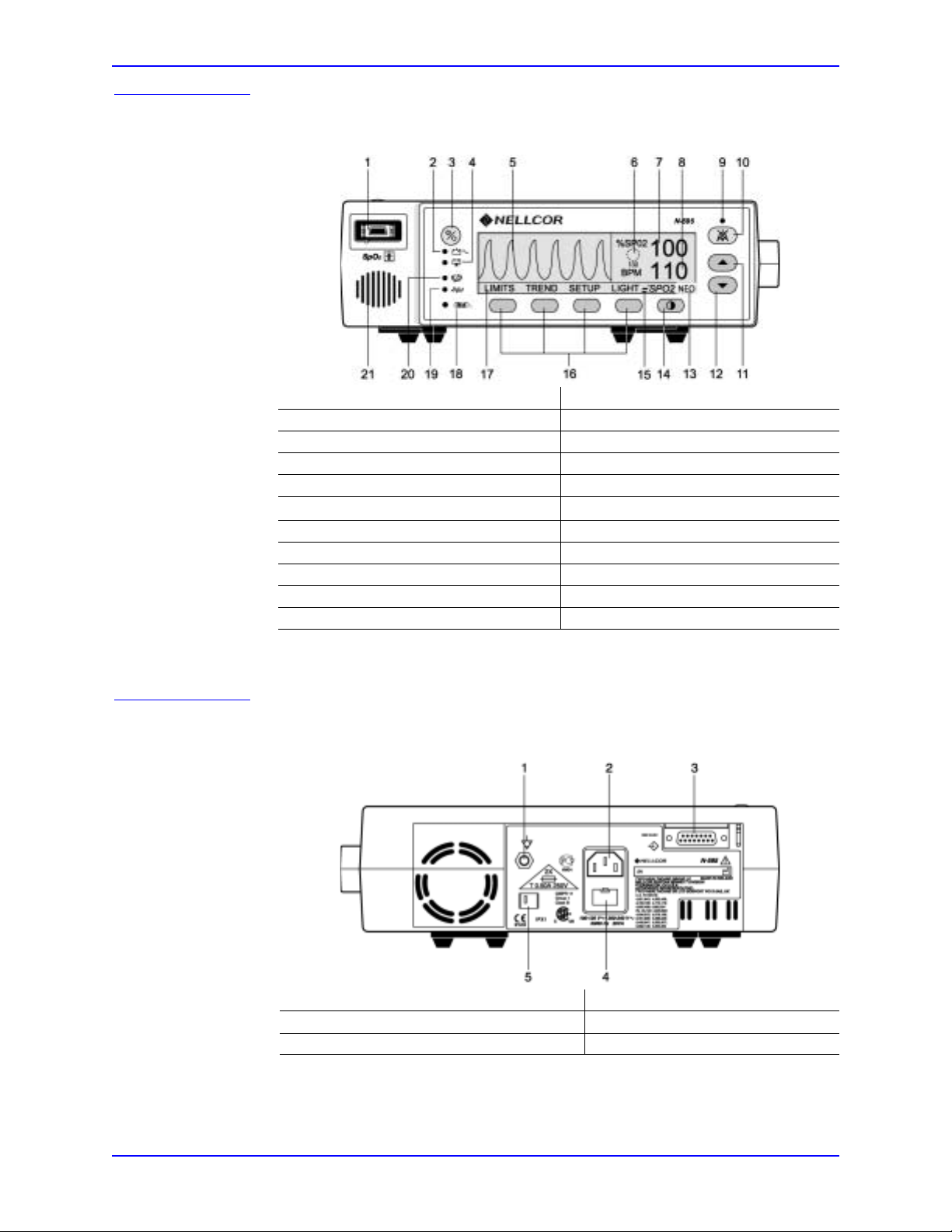
Front Panel
1. SpO2 Sensor Port 12. ADJUST DOWN Button
2. AC Power Indicator 13. Neonate Mode Indicator
3. ON/STANDBY Button 14. CONTRAST Button
4. Low Battery Indicator 15. Fast Response Mode Indicator
5. Wa veform Display 16. Softkeys
6. SatSeconds
7. %SpO
2 Display 18. Data In-Sensor Indicator
TM
Tim er
17. Menu Bar
8. Pulse Rate Display 19. Motion Indicator
9. Alarm Silence Display 20. Pulse Search Indicator
10. ALARM SILENCE Button 21. Speaker
11. ADJUST UP Button
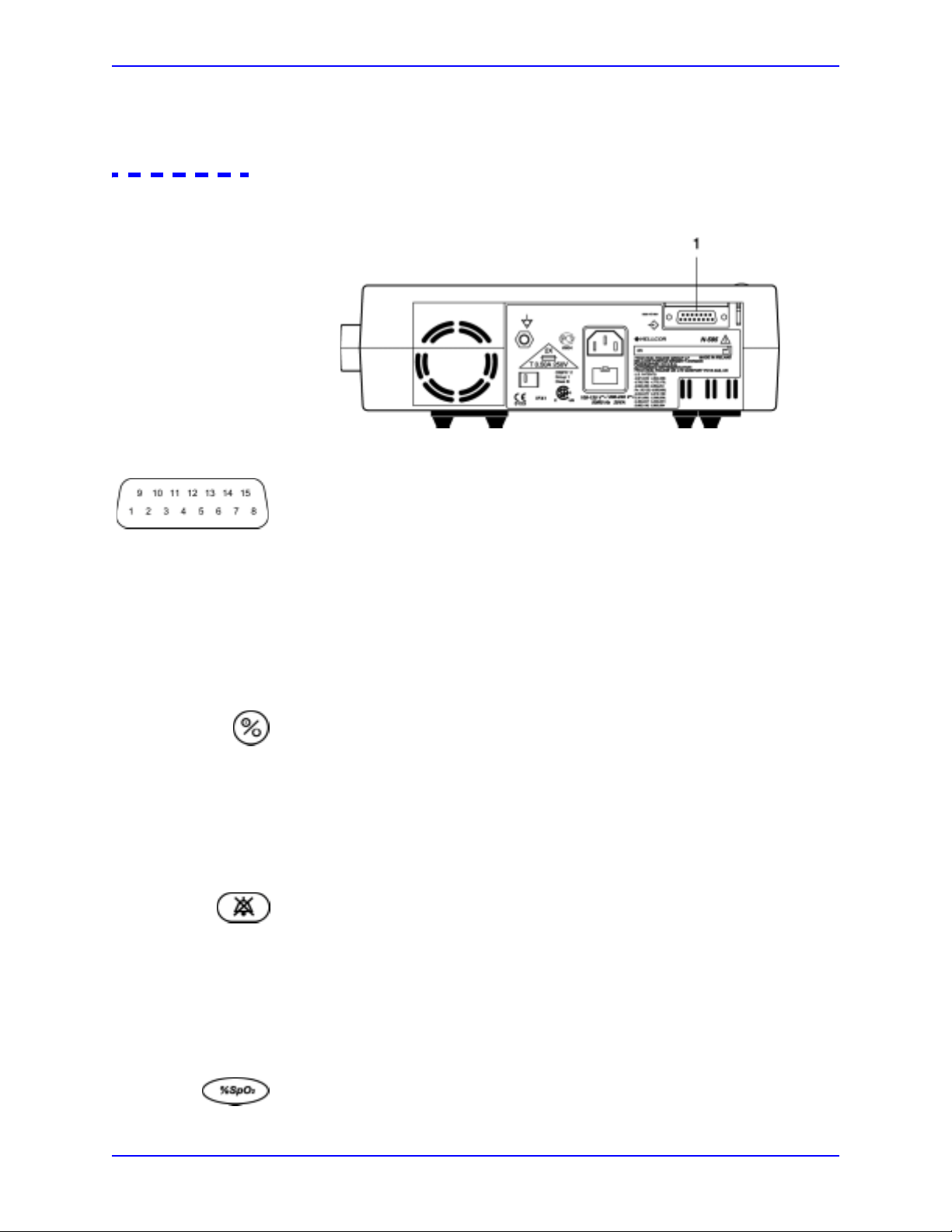
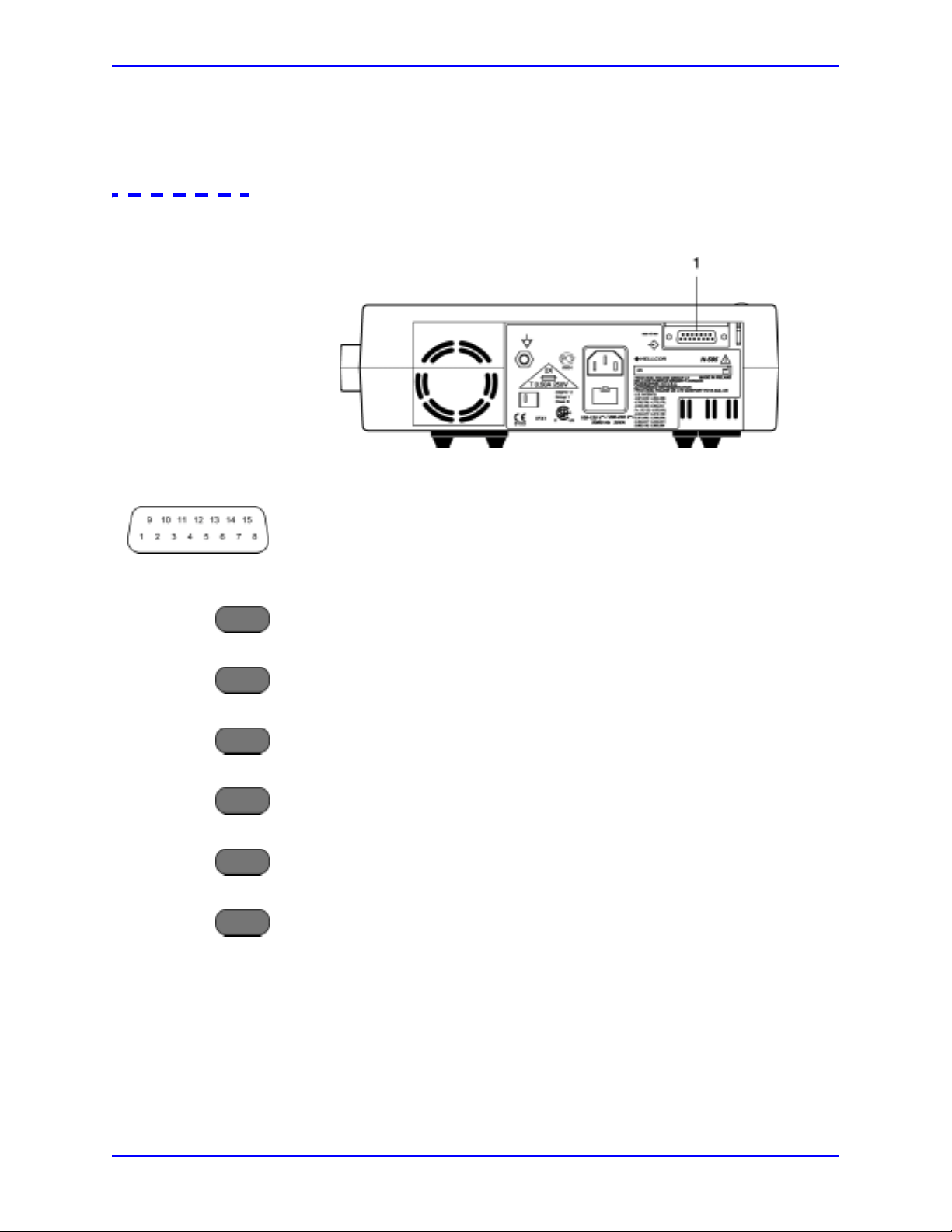
Rear Panel
Figure 1: N-595 Front Panel
1. Equipotential Terminal (Ground) 4. Fuse Receptacle
2. AC Power Connector 5. Supply Voltage Selector Switch
3. Data Port Connector
Figure 2: N-595 Rear Panel
4
Page 13

Softkey Menu
Introduction
The N-595 hierarchy is outlined below. The user chooses the type of trend data to
view by selecting either Monitor trend or Sensor trend data in the Trend menu.
Sensor sub-menu choices differ depending on what type of in-sensor data is stored
in the sensor chip, such as, event or loop.
The menu structure includes BACK softkey options that allow the user to move
back to the previous menu level without exiting the Trend menu entirely. Trend
data must be compiled on entry/reentry to the T rends menu. When the softkeys are
available, both BACK and EXIT options are available. The BACK softkey goes to
the previous level and the EXIT softkey goes to the main menu. If only one space
is available the BACK Softkey is included, this may require going back one or
two levels to get to an EXIT softkey.
The BACK and EXIT softkeys are positioned on the right-most softkeys,
respectively.
The below menu structure identifies:
• BOLDFACE TYPE — softkey title as displayed on the monitor
• Underlined Text
— description of the softkey menu item
• Italicized Text — the destination of the BACK and EXIT softkeys
(Main Menu)
LIMITS (Limits Menu)
- SELECT
-NEO
- ADULT
EXIT (to Main menu
TREND (Trend Menu
-MON (Monitor Menu)
--VIEW (Monitor Trend View Menu)
---DUAL
---SPO2
---PULSE
---NEXT (History/Amplitude Menu)
----HIST (Delete/Print2 Menu)
-----DELETE (delete Trends)
------“DELETE TRENDS”
-------YES (return to Main menu)
-------NO (back to Delete/Print menu)
-----PRINT
-----BACT (back to Hist/Amp menu)
-----EXIT (to Main menu)
----AMP (Amplitude Menu)
-----BACK (back to Hist/Amp menu)
-----EXIT (to Main menu)
----BACK (back to Monitor Trend View menu)
----EXIT (to Main menu)
)
)
N-595 5
Page 14

Introduction
--ZOOM (Monitor Trend Zoom Menu)
---TIME (for current view , cycle throu gh 48h, 36h, 12h, 8h, 4h, 2 h, 1h,
30m, 15m, 40s, 20s)
---SCALE (for current view, cycle through ±5, ±10, ±15, ±20, ±25,
±30, ±35, ±40 and ±50 of the max and min. values under the
cursor, default to 10 to 100 if there is no data point under the
cursor)
---AUTO (based on all of the graphed trend data: maximum value,
rounded up to nearest multiple of 10, minimum value, rounded
down to nearest multiple of 10 minus 10)
- - - BACK (back to Monitor menu)
--NEXT (Delete/Print1 Menu)
---DELETE
----“DELETE TRENDS?”
-----YES (to Main menu)
-----NO (back to Delete/Print1 menu)
---PRINT
- - - BACK (back to Monitor menu)
---EXIT (to Main menu)
- - BACK (back to Trend menu)
- SENSOR (Sensor/Event Menu)
(if Event data is in the sensor, the following menu, the Screen will remain in
the appropriate state until the next menu selection is made)
- - GRAPH (Graph Menu)
order; up/down also scroll through events in order)
---< (show previous graph, only available when there is a previous
graph)
---> (show next graph, only available when there is a next graph)
---PRINT
---BACK (back to Sensor menu)
--TABLE (Table Menu)
---^ (show previous table, only available when there is a previous
graph; bottom/top line repeats in new table)
---v (show next table, only available when there is a next graph;
bottom/top line repeats in new table)
---PRINT
- - - BACK (back to Sensor menu)
---EXIT (to Main menu)
(Sensor/Loop Menu)
will be displayed)
--VIEW (Sensor Trend View Menu)
---DUAL (shows SPO2+BPM)
---SPO2
---PULSE
--ZOOM (cycle through 2h. 1h, 30m, and 15m for current view)
- - PRINT
- - BACK (to Trend menu)
- EXIT (to Main menu)
SETUP (Setup Monitor Menu)
-VIEW (Setup View Menu)
- - PLETH
--BLIP
- - BACK (back to Setup menu)
- - EXIT (to Main menu)
- SENSOR (Setup Sensor Menu)
(display events #1-N, in inverse chronological
(If continuous-Loop data is in the sensor, the following
6
Page 15

Introduction
--DATA (On-screen options for SENSOR-R (Write-once Sensor) sensor
are: “SPO2, SPO2+BPM, DEFAULT.” On-screen options for
SENSOR-RW (rewritable sensor) are: “SPO2, SPO2+BPM,
DEFAUL T.” SELECT toggles SENSOR-R or SENSOR-RW
sensor type; up/down keys scroll through options in order.)
The SENSOR-R feature supports all of the current O
XIMAX
sensors.
- - - SELECT
- - - BACK (back to Setup Sensor menu)
---EXIT (to Main menu)
--MSG (Sensor Set Message Menu)
- - - BACK (back to Setup Sensor menu)
---EXIT (to Main menu)
- NEXT (Clock/Language Menu)
--CLOCK (Clock Menu)
---SET (Clock Set Menu)
----SELECT (press select to toggle through hours, minutes,
seconds, month, day, year; use up/down buttons to set each
selection)
----BACK (back to Clock/Language menu)
----EXIT (to Main menu)
--LANG (Language Setup Menu)
(use up/down buttons to toggle though
languages)
- - - BACK (back to Clock/Language menu)
--NEXT (Communication/Nurse Call Menu)
---COMM (Communication Port Configuration Menu)
----SELECT
----BACK (back to Communication/Language menu)
----EXIT (to Main menu)
---NCALL (Nurse Call Menu)
----NORM +
----NORM -
----BACK (back to Communication/Nurse Call menu)
----EXIT (to Main menu)
---NEXT (Analog/Mode Menu)
----ANALOG (Analog Voltage Select Menu)
-----0 VOLT
-----1 VOLT
-----STEP
-----BACK (back to Analog/Mode menu)
----MODE (Mode Menu)
-----BACK (back to Analog/Mode menu)
-----EXIT (to Main menu)
----BACK (back to Communication/Nurse Call menu)
----EXIT (to Main menu)
---BACK (back to Clock/Language menu)
- - BACK (back to Setup menu)
- EXIT (to Main menu)
LIGHT (Turns the display backlight on or off)
N-595 7
Page 16

Introduction
Related Documents
To perform test and troubleshooting procedures and to understand the principles
of operation and circuit analysis sections of this manual, you must know how to
operate the monitor. Refer to the N-595 operator's manual. To understand the
various Nellcor approved O
individual O
The latest version of the operator’s manual and the service manual are posted on
the Internet at:
Spare Parts and Accessories are posted on the Internet at:
http://www.mallinckrodt.com/respiratory/resp/Serv_Supp/Apartweb/main/PartAcceMenu.html
XI-MAX sensors that work with the monitor , refer to the
XI-MAX sensor's directions for use.
http://www.mallinckrodt.com/respiratory/resp/Serv_Supp/ProductManuals.html
8
Page 17

Routine Maintenance
Cleaning
WARNING: Do not spray, pour, or spill any liquid on the N-595, its
accessories, connectors, switches, or openings in the chassis.
For surface-cleaning and disinfecting follow your institution's procedures or:
•The N-595 may be surface-cleaned by using a soft cloth dampened with
either a commercial, nonabrasive cleaner or a solution of 70% alcohol in
water, and lightly wiping the surfaces of the monitor.
•The N-595 may be disinfected using a soft cloth saturated with a 10%
solution of chlorine bleach in tap water.
Before attempting to clean an SpO
enclosed with the O
specific to that sensor.
Periodic Safety Checks
The N-595 requires no calibration.
The battery should be replaced at least every 2 years. See Battery Replacement on
page 67.
The following checks should be performed at least every 24 months by a qualified
service technician.
1. Inspect the equipment for mechanical and functional damage.
2. Inspect safety labels for legibility . If the labels are damaged, contact Nellcor’s
Technical Services Department, 1.800.635.5267, or your local Nellcor
representative.
2 OXI-MAX sensor, read the directions for use
XI-MAX sensor. Each sensor model has cleaning instructions
Functional Checks
If the monitor has been visibly damaged or subjected to mechanical shock (for
example, if dropped), immediately perform the performance tests. See
Performance Tests on page 11.
N-595 9
Page 18

Routine Maintenance
Battery
The following checks should be performed at least every 2 years by a qualified
service technician.
1. Perform the electrical safety tests detailed in Safety Tests on page 33. If the
unit fails these electrical safety tests, refer to Troubleshooting on page 51.
2. Inspect the fuses for proper value and rating (F1 & F2 = 0.5 amp, 250 volts).
Nellcor recommends replacing the instrument's battery every 2 years. When the
N-595 is going to be stored for 3 months or more, remove the battery prior to
storage. To replace or remove the battery, refer to Disassembly Guide on page 63.
If the N-595 has been stored for more than 30 days, charge the battery as
described in Battery Charge on page 12. A fully discharged battery requires 14
hours with the monitor turned off, or 18 hours if it is in use, to receive a full
charge. The battery is being charged whenever the instrument is plugged into AC.
Note: If power stored in the battery is too low, the unit will not operate even
when plugged into AC. If this occurs, leave the unit plugged in to allow
the battery to charge as described in Battery Charge on page 12. After
approximately 10 minutes, the battery should have enough charge to
allow the unit to operate on AC.
10
Page 19

Performance Verification
Introduction
This section discusses the tests used to verify performance following repairs or
during routine maintenance. All tests can be performed without removing the
N-595 cover. All tests except the battery charge and battery performance tests
must be performed as the last operation before the monitor is returned to the user.
If the N-595 fails to perform as specified in any test, repairs must be made to
correct the problem before the monitor is returned to the user.
Equipment Needed
Table 1: Equipment Needed
Equipment Description
Digital Multimeter (DMM) Fluke Model 87 or equivalent
Durasensor
sensor
O
Safety Analyzer Must meet current AAMI ESI/1993 & IEC
Pulse oximetry cable DOC-10
Data interface cable EIA-232 cable (optional)
Stopwatch Manual or electronic
Nellcor model SRC-MAX Tester Provides testing for DigiCal compatible
Performance Tests
The battery charge procedure should be performed before monitor repairs
whenever possible.
XIMAX
®
OXI-MAX oxygen
oxygen sensor
DS-100A
MAX-A
60601-1/1998 specifications
Monitors
Note: This section is written using Nellcor factory-set defaults. If your
institution has pre configured custom defaults, those values will be
displayed. Factory defaults can be restored (see Reset Softkey on
page 40).
N-595 11
Page 20

Performance Verification
Battery Charge
Perform the following procedure to fully charge the battery.
1. Connect the monitor to an AC power source.
2. Verify that the monitor is off and that the AC Power/Battery Charging
3. Charge the battery for at least 14 hours with the monitor turned of f or 18 hours
Power-Up Performance
The power-up performance tests verify the following monitor functions:
indicator is lit.
with the monitor turned on.
Power-On Self-Test
• Power-On Self-Test on page 12
• Power-On Defaults and Alarm Range Limits on page 13
1. Connect the monitor to an AC power source.
2. Verify that the monitor is off and that the AC Power/Battery Charging
indicator is lit.
3. Do not connect any cables to the monitor.
4. Turn on the N-595 by pressing the ON/STANDBY button. Observe the
monitor front panel. The monitor must perform the following:
• Within 2 seconds all LEDs are illuminated, all pixels on the LCD display
are illuminated, and the backlight comes on.
12
• The indicators remain lighted.
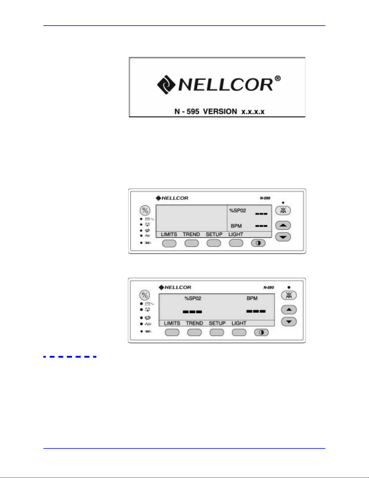
• The LCD display shows NELLCOR and the software version of the
N-595.
Page 21
Performance Verification
Note: The software “Version” displayed in the example below is X.X.X.X.The
actual software version will be displayed on your monitor.
•A 1-second beep sounds, indicating proper operation of the speaker, and
all indicators turn off except the AC Power/Battery Charging indicator
and the LCD screen.
•The N-595 begins normal operation.
PLETH VIEW:
BLIP (MAGNIFIED) VIEW
Power-On Defaults and Alarm Range Limits
Note: When observing or changing alarm limits, a time-out is in effect
(approximately 10 seconds). If no action is taken within the time-out, the
monitor automatically returns to the monitoring display.
Note: The descriptions that follow are based on the assumption that Pleth view
is the view that has been selected.
N-595 13
Page 22

Performance Verification
The steps for changing an alarm limit are the same if the view being used is Blip
(Magnified) view .
Note: Power-on defaults will be the factory-set defaults or the defaults set by
your institution.
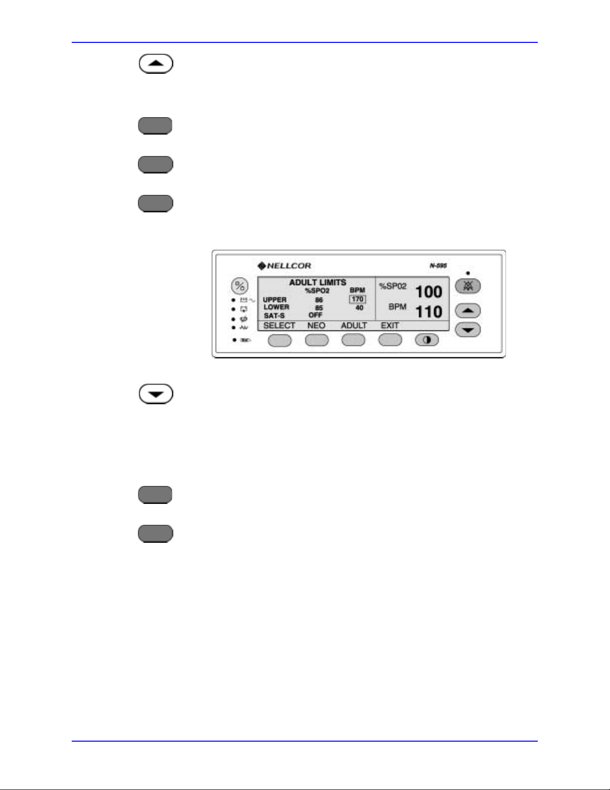
1. Turn on the N-595 by pressing the ON/STANDBY button.
LIMITS
2. Press the LIMITS softkey. Verify that the monitor emits a single beep and the
pleth view is replaced with a display of the alarm limits. The upper alarm limit
for %SpO
2 will indicate an alarm limit of “100” (or institutional default
setting) inside a box.
3. Press and hold the ADJUST DOWN button. Verify that the boxed number for
2 upper alarm limit reduces to a minimum of “86.”
%SpO
Note: A decimal point in the display indicates that the alarm limits have been
changed from factory default values.
14
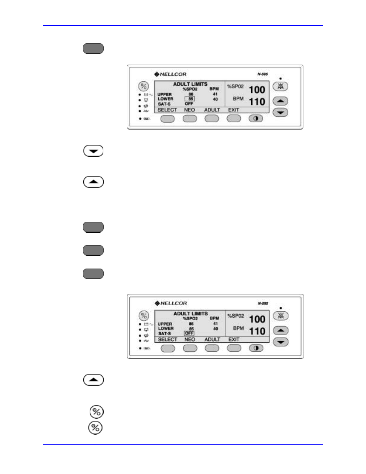
SELECT
4. Press the SELECT softkey . Verify that the monitor emits a single beep and the
box moves to the %SpO
2 lower alarm limit of “85” (or your institutional
default setting).
5. Press and hold the ADJUST DOWN button and verify that the %SpO
2 lower
alarm limit display reduces to a minimum of “20.”
Page 23
Performance Verification
6. Press and hold the ADJUST UP button and verify that the %SpO2 lower alarm
limit display cannot be raised past the upper alarm limit setting of “85.”
EXIT
LIMITS
SELECT
7. Press the EXIT softkey.
8. Press the LIMITS softkey
9. Press the SELECT softkey three times. Verify that the monitor emits a beep
after each keystroke. The Pulse upper alarm limit should be “170” and should
be boxed.
10. Press and hold the ADJUST DOWN button.
EXIT
LIMITS
11. Verify that the minimum displayed value is “41” for the BPM upper alarm
limit.
12. Press the EXIT softkey.
13. Press the LIMITS softkey.
N-595 15
Page 24
Performance Verification
SELECT
14. Press the SELECT softkey four times. Verify that the pulse rate lower alarm
limit display indicates an alarm limit of “40” and is boxed.
15. Press and hold the ADJUST DOWN button. Verify that the boxed pulse rate
lower alarm limit display reduces to a minimum of “30.”
16. Press and hold the ADJUST UP button and verify that the boxed pulse rate
lower alarm limit display cannot be adjusted above the pulse rate upper alarm
limit of “40.”
EXIT
LIMITS
SELECT
17. Press the EXIT softkey.
18. Press the LIMITS softkey.
19. Press the SELECT softkey two times. Verify that SatSeconds SAT-S alarm is
selected.
20. Press the ADJUST UP button repeatedly and verify that the SatSeconds alarm
display cycles from OFF through 10, 25, 50, 100, OFF.
16
21. Press the ON/STANDBY button to turn the monitor off.
22. Press the ON/STANDBY button to turn the monitor back on.
Page 25

Performance Verification
LIMITS
23. Press the LIMITS softkey. Verify that the %SpO2 upper alarm limit display is
boxed and indicates an alarm limit of “100.”
24. Verify that the %SpO
2 lower alarm limit display is boxed and indicates an
alarm limit of “85.”
25. Verify that the SatSeconds SAT-S alarm is set to OFF.
26. Verify that the pulse rate upper alarm limit display is boxed and indicates an
alarm limit of “170.”
27. Verify that the pulse rate lower alarm limit display is boxed and indicates an
alarm limit of “40.”
28. Press the ON/STANDBY button to turn the monitor off.
Operational Setup
Operational setup procedures verify and set up the following parameters.
• Alarms and Alarm Silence on page 18
• Alarm Volume Control on page 20
• Pulse Tone Volume Control on page 20
• Nurse Call on page 21
• Analog Output on page 22
• Operation on Battery Power on page 23
N-595 17
Page 26
Performance Verification
Alarms and Alarm Silence
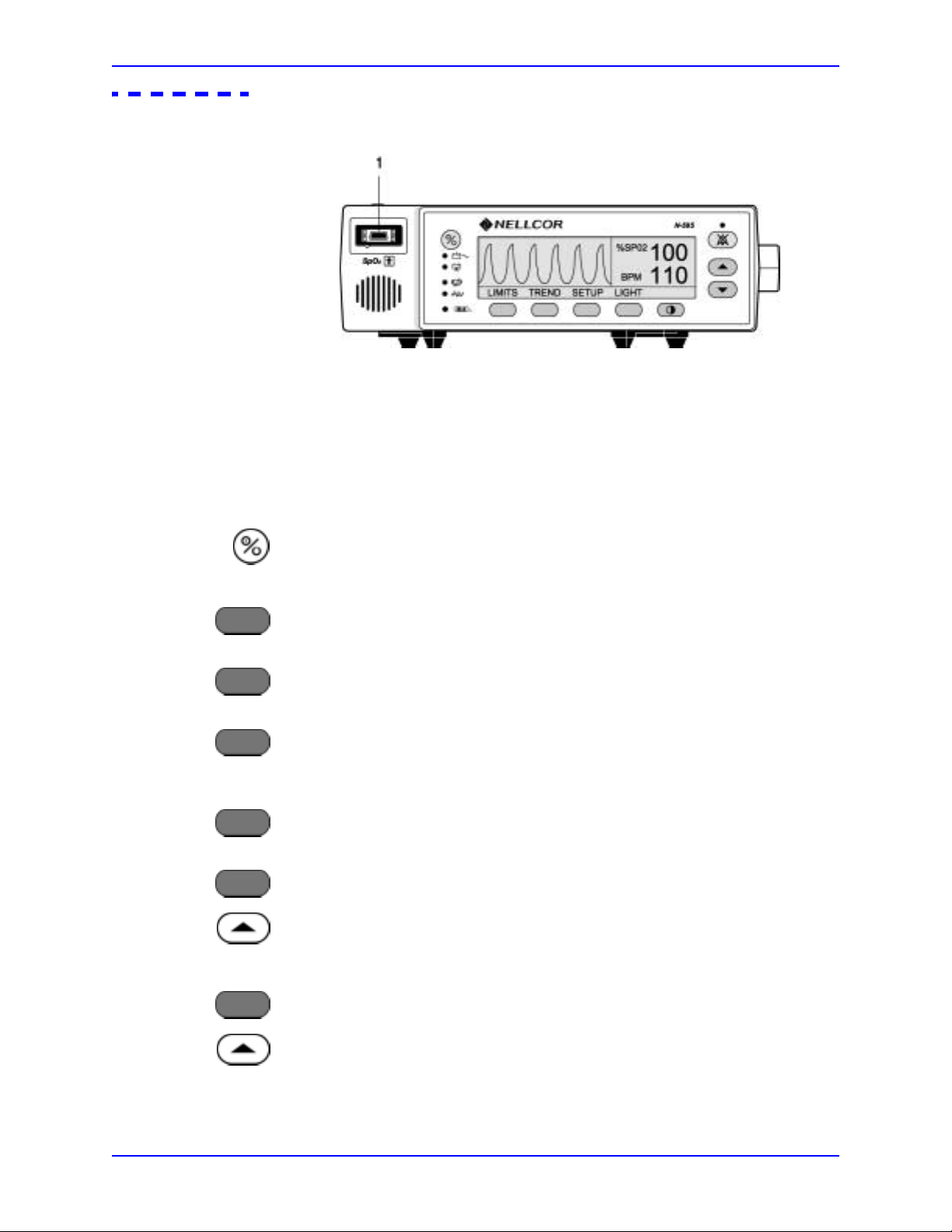
1. Connect the DOC-10 monitor cable to the monitor sensor port.
1. Sensor Port
SETUP
VIEW
PLETH
LIMITS
SELECT
2. Connect the DS-100 O
XI-MAX sensor to the DOC-10 cable and your finger.
3. Press the ON/STANDBY button to turn the monitor on.
4. Press the SETUP softkey.
5. Press the VIEW softkey.
6. Press the PLETH softkey. Verify that the %SpO
2 and pulse rate.
SpO
2 and BPM indicate your
7. Press the LIMITS softkey.
8. Press the SELECT softkey to select SpO
9. Press the ADJUST UP button until the SpO
2 lower alarm limit.
2 lower alarm limit indicates 99.
18
SELECT
10. Press the SELECT softkey three times to select pulse rate lower alarm limit.
11. Press the ADJUST UP button until the pulse rate lower alarm limit indicates
160.
12. Verify the following monitor reactions:
Page 27

Performance Verification
• The plethysmograph waveform tracks your pulse rate.
• The pulse tone is heard.
•Your SpO
2 and pulse rate are flashing in the %SpO2 and BPM displays.
• The audible alarm sounds, indicating that both parameters have violated
the alarm limits.
13. Press and hold the ALARM SILENCE button until the BPM display indicates
“SEC.” Continue to press the ALARM SILENCE button and press the
ADJUST DOWN button until “60” is displayed in the %SpO
2 display.
14. Press the ALARM SILENCE button.
15. With the monitor’s alarm silenced, verify the following:
• The alarm remains silenced for 60 seconds.
• The ALARM SILENCE indicator lights.
• The %SpO
2 and BPM displays continue to flash.
• The pulse tone is still audible.
• The audible alarm returns in approximately 60 seconds.
16. Press and hold the ALARM SILENCE button until the BPM display indicates
“SEC.” Continue to press the ALARM SILENCE button and press the
ADJUST DOWN button until “30” is displayed in the %SpO
2 display.
17. Press the ADJUST UP button and verify that the displays indicate 60 SEC,
90 SEC, 120 SEC, and OFF. Release the ADJUST UP button when the
display indicates “OFF.”
18. Press and release the ALARM SILENCE button. Verify that the monitor’s
ALARM SILENCE indicator flashes.
19. Wait approximately 3 minutes. Verify that the monitor’s alarm does not
return. After 3 minutes, the monitor’s alarm silence reminder beeps three
times, and will continue to do so at approximately 3-minute intervals.
N-595 19
Page 28

Performance Verification
Alarm Volume Control
After completing Alarms and Alarm Silence on page 18, perform the following
procedure.
1. Press and hold the ALARM SILENCE button and verify the following:
2. While still pressing the ALARM SILENCE button, press the ADJUST
• “OFF” is displayed for approximately 3 seconds.
• After 3 seconds, a steady tone is heard at the default alarm volume setting,
the %SpO
2 display indicates “VOL,” and the BPM display indicates the
default setting of 7.
DOWN button until an alarm volume setting of 1 is displayed. Verify that the
volume of the alarm has decreased but is still audible.
3. Continue pressing the ALARM SILENCE button and press the ADJUST UP
button to increase the alarm volume setting to a maximum value of 10. Verify
that the volume increases.
4. Continue pressing the ALARM SILENCE button and press the ADJUST
DOWN button until a comfortable audio level is attained.
5. Release the ALARM SILENCE button. The tone will stop.
Pulse Tone Volume Control
After completing Alarm Volume Control on page 20, perform the following
procedure.
1. Press the ADJUST UP button and verify that sound level of the beeping pulse
tone volume increases.
20
2. Press the ADJUST DOWN button and verify that the sound level of the
beeping pulse tone volume decreases until it is no longer audible.
3. Press the ADJUST UP button to return the beep volume to a comfortable
level.
Page 29
Nurse Call
Performance Verification
4. Remove the OXI-MAX sensor from your finger. Disconnect the DOC-10
monitor cable and the O
XI-MAX sensor.
1. Data Port Connector
1. Connect the negative lead of a voltmeter to pin 5 and positive lead to pin 11 of
the data port connector (1) on the back of the monitor. Ensure that the audible
alarm is not silenced or turned off.
2. Connect the SRC-MAX tester to the DOC-10 sensor cable.
3. Connect the DOC-10 sensor cable to the monitor SpO
2 connector.
4. Turn on the monitor and wait for the monitor to complete POST.
Note: The monitor should indicate a %SpO
2 alarm of 75.
5. Verify an output voltage at pin s 5 and 11 between +5 to +12 VDC.
6. Press the ALARM SILENCE button. With no active audible alarm, the output
voltage at pins 5 and 11 must be between -5 to -12 VDC. This verifies the
RS-232 Nurse Call function.
7. With the instrument in an alarm condition, use a digital voltmeter (DVM) to
verify that there is no continuity (1 megohms or greater) between pins 8 and
15 and that there is continuity (60 ohms or less) between pins 7 and 15.
8. Press the SRC-MAX tester %SpO
N-595 21
2 button to change the %SpO2 to 90.
Page 30
Performance Verification
G
Analog Output
9. Use a DVM to verify that there is continuity between pins 8 and 15 and that
there is no continuity between pins 7 and 15. This verifies the solid state
Nurse Call function.
1 Data Port Connector
SETUP
NEXT
NEXT
NEXT
ANALO
1 VOLT
1. Connect the negative lead of a voltmeter to pin 10 and the positive to lead pin
6 of the data port connector (1) on the back of the monitor.
2. Press the SETUP softkey.
3. Press the NEXT softkey.
4. Press the NEXT softkey.
5. Press the NEXT softkey.
6. Press the ANALOG softkey.
7. Press the 1 VOLT softke y.
8. Verify that the monitor’s output voltage is +1.0 ± 0.025 VDC. This verifies
the analog SpO
2 function.
9. Leave the negative lead connected to pin 10 and verify 1.0 ± 0.025 VDC on
pins 13 and 14. This verifies the monitor’s BPM and Pleth function.
22
Page 31

Performance Verification
G
Note: If step 8 takes more than 2 minutes to complete, the analog output will
time out. Repeat steps 2 through 6 to initiate the analog output.
10. Move the positive lead back to pin 6.
SETUP
NEXT
NEXT
NEXT
ANALO
0 VOLT
11. Press the SETUP softkey.
12. Press the NEXT softkey.
13. Press the NEXT softkey.
14. Press the NEXT softkey.
15. Press the ANALOG softkey.
16. Press the 0 VOLT softkey.
17. Verify that the monitor’s output voltage is +0.0 ± 0.025 VDC.
18. Leave the negative lead connected to pin 10 and verify 0.0 ± 0.025 VDC on
pins 13 and 14.
Note: If step 16 takes more than 2 minutes to complete, the analog output will
time out. Repeat steps 10 through 14 to initiate the analog output.
19. Disconnect the voltmeter from the instrument.
Operation on Battery Power
1. Disconnect the instrument from AC power and verify that the AC POWER
indicator turns off.
2. Verify that the monitor continues monitoring normally and that the LOW
BATTERY indicator is not lit.
N-595 23
Page 32

Performance Verification
General Operation
LED Excitation Test
Note: If the LOW BATTERY indicator is illuminated, perform Battery Charge
on page 12.
3. Connect the monitor to AC power and verify that the AC POWER indicator
turns on and that the instrument is monitoring normally.
The following tests are an overall performance check of the system:
• LED Excitation Test on page 24.
• Operation with a Live Subject on page 25.
This procedure uses normal system components to test circuit operation. A
Nellcor O
XIMAX oxygen sensor, model MAX-A, is used to examine LED intensity
control. The red LED is used to verify intensity modulation caused by the LED
intensity control circuit.
1 Sensor Port
1. Connect the monitor to an AC power source.
2. Connect a DOC-10 pulse oximetry cable to the monitor sensor port.
24
3. Connect a MAX-A O
XI-MAX sensor to the OXI-MAX sensor-input cable.
4. Press the ON/STANDBY button to turn the monitor on.
5. Leave the O
XI-MAX sensor open with the LEDs and photo detector visible.
Page 33

Performance Verification
6. After the monitor completes its normal power-up sequence, verify that the
O
XI-MAX sensor LED is brightly lit.
7. Slowly move the O
element of the O
the LED approaches the optical O
decreases.
8. Open the O
9. Repeat step 7 and the intensity will again decrease. This variation is an
indication that the microprocessor is in proper control of LED intensity.
10. Press the ON/STANDBY button to turn the monitor off.
Operation with a Live Subject
Patient monitoring involves connecting the OXIMAX sensor to a live subject for a
qualitative test.
.
XI-MAX sensor LED in proximity to the photo detector
XI-MAX sensor (close the OXI-MAX sensor slowly). Verify, as
XIMAX sensor, that the LED intensity
XIMAX sensor and notice that the LED intensity increases.
1 Sensor Port
1. Ensure that the monitor is connected to an AC power source.
2. Connect a DOC-10 pulse oximetry cable to the monitor sensor port.
3. Connect a Nellcor O
XIMAX MAX-A oxygen OXIMAX sensor to the pulse
oximetry cable.
4. Clip the MAX-A to the subject as recommended in the O
XIMAX sensor's
directions for use.
N-595 25
Page 34

Performance Verification
5. Press the ON/STANDBY button to turn the monitor on and verify that the
monitor is operating.
6. The monitor should stabilize on the subject's physiological signal in about 15
to 30 seconds. Verify that the oxygen saturation and pulse rate values are
reasonable for the subject.
Pulse Oximetry Functional Tests
These tests utilize the pulse oximetry functional tester (Nellcor model
SRC-MAX) to verify the performance of the N-595 monitor. See Figure 3.
All of these tests should be done in sequence.
Introduction
26
1 DOC-10 Cable Connector 6 % Modulation Select Button
2 RED LED Drive Indicator 7 % SpO
3 Not Used For N-595 8 Light Level Selection Button
4 Not Used For N-595 9 Pulse Rate Selection Button
5 Battery Low Indicator 10 INFRARED LED Drive Indicator
Figure 3: SRC-MAX O
2 Select Button
XIMAX Oximetry Tester
The SRC-MAX functional tester allows qualified technicians to functionally test
Nellcor O
XIMAX technology-based pulse oximeters and OEM OXIMAX
technology-based monitors. The technician must perform the test setup procedure
Page 35

Performance Verification
before performing tests 1 through 4. The following is a brief description of each
test:
• Test Setup — This procedure establishes the baseline for all the other
tests. The T est Setup procedure must be performed before performing any
or all of the SRC-MAX tests.
Initial Setup
• Test 1: BPM — This procedure simulates an O
XIMAX sensor attached to a
patient indicating 60 BPM and 200 BPM. The test setup procedure sets up
Test 1 for 60 BPM.
• Test 2: SpO
2 — This procedure simulates an OXIMAX sensor attached to a
patient, indicating 75 percent blood oxygen saturation and 90 percent
blood oxygen saturation. The test setup procedure sets up Test 2 for 75
percent blood oxygen saturation.
• Test 3: Modulation — This procedure simulates an O
XIMAX sensor
attached to a patient indicating low and high pulse strength. The test setup
procedure sets up Test 3 for low pulse strength.
• Test 4: Light — This procedure simulates an O
XIMAX sensor attached to a
patient indicating low and high light level passing through the patient at
the sensor site. The test setup procedure sets up Test 4 for low light level.
1.Sensor Port
1. With the monitor turned off, connect the DOC-10 pulse oximetry cable to the
sensor port.
2. Connect the SRC-MAX tester to the other end of the DOC-10 cable.
3. Turn on the monitor by pressing the ON/STANDBY button.
N-595 27
Page 36

Performance Verification
4. After the monitor completes POST, the monitor will:
Test #1: BPM
•be in SpO
• display an %SpO
2 alarm
2 of 75 (pass criteria is 73 to 77 %SpO2 inclusive)
• display a pulse rate of 60 (pass criteria is 57 to 63 BPM inclusive)
• pulse amplitude indicator - display low level modulation (low amplitude
pulse amplitude indicator)
1. Press the SRC-MAX % Pulse Rate selection button. The SRC-MAX Pulse
Rate 200 LED will light.
2. The monitor BPM will increase to 200 and stabilize at 200 BPM. The test pass
criteria is 197 to 203 BPM inclusive.
3. The monitor will display:
• 75 %SpO
2
• 200 BPM (pass criteria is 197 to 203 BPM inclusive)
•alarm
• pulse amplitude indicator - low level modulation
28
Page 37

Performance Verification
4. Press the SRC-MAX Pulse Rate select button. The SRC-MAX Pulse Rate 60
LED will light.
5. The monitor pulse rate will decrease to 60 and stabilize at 60 BPM. The test
pass criteria is 57 to 63 BPM inclusive.
6. The monitor will display:
Test #2: SpO2
• 75 %SpO
2
• 60 BPM (test pass criteria is 57 to 63 BPM inclusive)
•alarm
• pulse amplitude indicator - low level modulation
1. Press the SRC-MAX %SpO2 select button. The SRC-MAX %SpO2 90 LED
will light.
2. The monitor will display three dashes until the SRC-MAX stabilizes at 90
2. The test pass criteria is 88 to 92 %SpO2 inclusive.
%SpO
N-595 29
Page 38

Performance Verification
3. The monitor will display:
• 90 %SpO
2 (pass criteria is 88 to 92 %SpO2 inclusive)
•60 BPM
• no alarm
• pulse amplitude indicator - low level modulation
4. Press the SRC-MAX %SpO
2 select button. The SRC-MAX %SpO2 75 LED
will light.
5. The monitor will display three dashes until the SRC-MAX stabilizes at 75
%SpO
2. The test pass criteria is 73 to 77 %SpO2 inclusive.
6. The monitor will display:
• 75 %SpO
•60 BPM
•alarm
• pulse amplitude indicator - low level modulation
Test #3: Modulation Level
1. Press the SRC-MAX % Modulation selection button. The SRC-MAX %
Modulation LED will light.
2 (pass criteria is 73 to 77 %SpO2 inclusive)
30
Page 39

Performance Verification
2. The monitor pulse amplitude waveform will initially increase in amplitude
and then stabilize.
3. The monitor will display:
• 75 %SpO
2 (test pass criteria is 73 to 77 %SpO2 inclusive)
• 60 BPM (test pass criteria is 57 to 63 BPM inclusive)
•alarm
• pulse amplitude indicator - high level modulation
4. Perform Test #1: BPM on page 28. The pulse amplitude indicator should
indicate high level modulation.
5. Perform Test #2 : SpO2 on page 29. The pulse amplitude indicator should
indicate high level modulation.
6. Press the SRC-MAX % Modulation selection button. The SRC-MAX %
Modulation LED will light.
7. The monitor pulse amplitude waveform will decrease in amplitude.
N-595 31
Page 40

Performance Verification
8. The monitor will display:
Test #4: Light
• 75 %SpO
2
•60 BPM
•alarm
• pulse amplitude indicator - low level modulation
9. Perform Test #1: BPM on page 28. The pulse amplitue indicator should
indicate low level modulation.
10. Perform Test #2: Sp O2 on page 29. The pulse amplitue indicator should
indicate low level modulation.
1. Press the SRC-MAX Light Level selection button. The SRC-MAX Light
Level LED will light.
2. The monitor pulse amplitude waveform will initially increase in amplitude
and then stabilize.
3. The monitor will display:
• 75 %SpO
2 (test pass criteria is 73 to 77 %SpO2 inclusive)
• 60 BPM (test pass criteria is 57 to 63 BPM inclusive)
•alarm
32
• pulse amplitue indicator - high level modulation
Page 41

Performance Verification
4. Perform Test #1: BPM on page 28. The pulse amplitue indicator should
indicate high level modulation.
5. Perform Test #2 : SpO2 on page 29. The pulse amplitue indicator should
indicate high level modulation.
6. Press the SRC-MAX Light Level selection button. The SRC-MAX Light
Level LED will light.
7. The monitor pulse amplitude waveform will decrease in amplitude.
8. The monitor will display:
Safety Tests
• 75 %SpO
2
•60 BPM
•alarm
• low level modulation
9. Perform Test #1: BPM on page 28. The pulse amplitue indicator should
indicate low level modulation.
10. Perform Test #2: Sp O2 on page 29. The pulse amplitue indicator should
indicate low level modulation.
11. Disconnect all equipment and turn off the monitor.
The N-595 safety tests meet the standards of, and are performed in accordance
with, IEC 60601-1 (EN 60601-1, Amendment 1, Amendment 2,) and UL 2601-1,
for instruments classified as Class 1 and TYPE BF and ANSI/AAMI Standard
ES1.
Applicable tests for these standards are listed below . Technicians must be familiar
with the Standards applicable to the technicians institution and country. Test
equipment and its application must comply with the applicable standard.
• Ground Integrity on page 101 for test value.
N-595 33
Page 42

Performance Verification
• Earth Leakage Current on page 102 for test values.
• Enclosure Leak age Current on page 102 for test values.
• Patient Applied Risk Current on page 102 for test values.
• Patient Applied Risk Current on page 102 for test values.
Note: Patient Applied Risk Current and Patient Isolation Risk Current: The
leakage test lead from the test equipment must be connected to the N-595
SpO
2 Sensor Port through the DOC-10 pulse oximetry cable using a male
9-pin “D” type connector that has all pins shorted together. During these
tests the monitor will display “EEE 10,” after the “Nellcor” screen.
34
Page 43

Power-On Settings and Service Functions
Introduction
This section discusses how to reconfigure power-on default values and access the
service functions.
Power-On Settings
The following paragraphs describe how to change power-on default settings.
By using softkeys as shown in Figure 1 on page 4, the user can change alarm
limits, the type of display, baud rate, time and date, and trends to view.
Some values cannot be saved as power-on default values. An SpO
limit less than 80 will not be saved as a power-on default. Audible Alarm Off will
not be accepted as a power-on default. An attempt to save either of these values as
default will result in an invalid tone. These limits can be adjusted lower for the
current patient, but they will be lost when the instrument is turned off.
A decimal point is added to the right of a display when the alarm limit for that
display has been changed to a value that is not a power-on default value. If the
new value is saved as a power-on default value, the decimal point will be
removed. By using the service functions, changes can be saved as power-on
default values.
Factory Default Settings
Factory default settings are divided into two groups, adult and neonate. Default
settings may be changed to institutional default settings; refer to Setting
Institutional Defaults (Sample) on page 47.
Neonate Default Settings
2 lower alarm
Table 2: Neonate Alarm Limit Factory Defaults
Monitoring Mode Setting
Note: Bold entries are different than adult default settings.
%SpO2 Lower Alarm Limit 80%
N-595 35
Page 44

Power-On Settings and Service Functions
Table 2: Neonate Alarm Limit Factory Defaults
Monitoring Mode Setting
Note: Bold entries are different than adult default settings.
2 Upper Alarm Limit 95%
%SpO
Alarm Silence Duration 60 seconds
Alarm Silence Duration Off Setting Disabled
Alarm Silence Reminder Enabled
Alarm Volume 7 of 10
Data Port Baud Rate 9600
Data Port Protocol ASCII
Display Contrast Midrange
Display Format Pleth
O
XIMAX Sensor Event Record Type SpO2
Language English
Nurse Call Polarity Normally Low
Pulse Beep Volume 4 of 10
Pulse Rate Lower Alarm Limit 90 beats per minute
Pulse Rate Upper Alarm Limit 190 beats per minute
SatSeconds Off
Sensor Adjust Enabled Yes
Trend Display %SpO
2
36
Page 45

Adult Default Settings
Monitoring Mode Setting
Note: Bold entries are different than neonate default settings.
%SpO2 Lower Alarm Limit 85%
%SpO
Alarm Silence Duration Off Setting Disabled
Alarm Silence Duration 60 seconds
Alarm Silence Reminder Enabled
Alarm Volume 7 of 10
Data Port Baud Rate 9600
Power-On Settings and Service Functions
Table 3: Adult Alarm Factory Defaults
2 Upper Alarm Limit 100%
Service Functions
Data Port Protocol ASCII
Display Contrast Midrange
Display Format Pleth
XIMAX Sensor Event Record Type SpO2
O
Language English
Nurse Call Polarity Normally Low
Pulse Beep Volume 4 of 10
Pulse Rate Lower Alarm Limit 40 beats per minute
inclusive
SatSeconds Off
Sensor Adjust Enabled Yes
Trend Display %SpO
170 beats per minute
2
Service functions can be used to select institutional defaults and to access
information about the patient or instrument. Only a Nellcor Customer Service
Engineer should access some of the items available through the service functions.
These items will be noted in the text that follows.
N-595 37
Page 46

Power-On Settings and Service Functions
Accessing the Service Functions
All service functions are accessible when the DOC-10 pulse oximetry cable is
disconnected from the monitor. Disconnect the O
extension cable; or, disconnect the MC-10 extension cable from the instrument.
1. Turn on the N-595 by pressing the ON/STANDBY button.
2. Wait for monitor power-on self-test to complete.
XIMAX sensor from the MC-10
LIGHT
3. Simultaneously press and hold the LIGHT softkey and the CONTRAST
button until the service softkeys are displayed.
Note: The service function is only accessible from the main menu display. The
menu bar will change to the headings listed below.
Note: If the above step is performed with a pulse oximetry cable connected,
only the PARAM and EXIT softkeys appear on the screen.
The following list can be used as a quick reference showing how to reach different
softkey functions. Items reached through the PARAM softkey can be accessed
during normal operation. Functions provided by the PRINT and NEXT softkeys
cannot be accessed when a pulse oximetry cable is connected to the instrument.
Each of the various functions is described in the text that follows.
38
PARAM (Service Menu)
- RESET
- - RESET DEFAULTS?
---YES (resets parameters to factory defaults, sounds three tones to
indicate that defaults have reset)
---NO (back to Service menu)
-SAVE
--SAVE DEFAULTS?
---YES (saves parameters as default settings, sounds three tones to
indicate that defaults have been saved)
---NO (back to Service menu)
- SENSOR (enables/disables sensor trend writing on rewritable sensors)
- - BACK (back to Service menu)
Page 47

Exit Softkey
Power-On Settings and Service Functions
- - EXIT (back to Main menu, sounds three tones to indicate that defaults
have reset)
- BACK (back to Service menu)
PRINT
- TREND
-ERRLOG
-INSTAT
-INFO
NEXT
-DOWNLD (for downloading monitor software)
- ALARMS
- - SELECT
---ALLOW OFF? (Allows alarms to be turned off)
select Yes/No)
---OFF REMINDER? (enables/disables Alarm Off reminder)
down buttons select Yes/No)
- - BACK (back to Service menu)
- NEXT (back to Service menu)
- EXIT (back to Main menu)
(up/down buttons
(up/
Next Softkey
EXIT
NEXT
The EXIT softkey returns the monitor to the Main menu.
There are not enough softkeys to display all of the options that are available at
some levels of the menu. Pressing the NEXT softkey allows you to view
additional options available at a given menu level.
N-595 39
Page 48

Power-On Settings and Service Functions
R
Param Softkey Menu
Reset Softkey
PARAM
RESET
When the PARAM softkey is pressed, the function of the softkeys changes as
shown below. These options can be accessed without disconnecting the pulse
oximetry cable from the instrument.
.
The RESET softkey can be used if any settings stored in memory have been
changed from factory default values. If YES is pressed, the instrument sounds
three tones and the settings return to factory default values. When NO is pressed,
no changes are made to the settings stored in memory.
Save Softkey
SAVE
Sensor Softkey
SENSO
When adjustable values are changed from factory default, the SAVE softkey can
be used to preserve the settings as institutional power-on default values. Pressing
YES stores the current settings in memory. The instrument sounds three tones
indicating that the changes have been saved as power-on default values. The new
saved values will continue to be used through power-on and off cycles until they
are changed and saved again, or until they are reset. If NO is pressed, the changed
values will not be saved.
Note: An invalid tone indicates that a parameter value cannot be saved as a
power-on default. See Power-On Settings on page 35. Along with the
invalid tone, a message will be displayed indicating which parameter
could not be saved as a power-on default.
The SENSOR softkey enables/disables the Sensor Event Record function.
40
Page 49

Print Softkey Menu
Power-On Settings and Service Functions
PRINT
Accessing the PRINT softkey makes four printouts available. See Data Port
Interface Protocol on page 105, for information about how to make connections to
the data port and how data is presented in a printout. The appropriate printout can
be selected by pressing the corresponding softkey. The softkey configuration that
appears after the PRINT softkey has been pressed is shown below.
Up to 48 hours of trend data can be viewed on the printouts described below.
When the monitor is turned on, trend data is recorded every 4 seconds. As an
example, an instrument that is used 6 hours a week would take approximately 8
weeks to fill its memory.
Note: The two-letter codes and the symbols that occur in the printout are
described in Table 19 on page 120.
N-595 41
Page 50

Power-On Settings and Service Functions
G
Trend Sof tkey
A Trend printout will include all data recorded for up to 48 hours of monitoring
TREND
since the last Delete Trends was performed. A new trend point is recorded every 4
seconds. The figure below is an example of a Trend printout.
ERRLOG Softkey
ERRLO
The first row of the printout includes information about the type of instrument
delivering the information, the software level, type of printout, and alarm
parameters. The second line lists the headings for the columns. These lines are
printed out every 25 lines, or when a change to an alarm limit is made.
Patient data is represented with a date and time stamp for the data. In the examp le
above, the “- - -” means that an O
XIMAX sensor was connected but the signal
quality of the data being received was too low for the monitor to interpret the data.
Patient data that is outside of an alarm limit is marked with an asterisk (*).
At the end of the printout “Output Complete” will be printed. This indicates that
there was no corruption of data. If the Output Complete statement is not printed at
the end of the printout, the data must be considered invalid.
This softkey is for Nellcor’s Customer Service Engineering Only.
A list of all the errors recorded in memory can be obtained by pressing the
ERRLOG softkey. The first line lists the type of instrument producing the
printout, software level, type of printout, and the time of the printout. The second
42
Page 51

INSTAT Softkey
Power-On Settings and Service Functions
line of the printout consists of column headings. If nothing prints out, there have
been no errors. An example of an Errlog printout is shown below.
This softkey is for Nellcor’s Customer Service Engineering Only.
DELETE
The DELETE softkey , described in the operator's manual, allows the user to delete
the most recent trend data. The current trend data, along with the deleted trends,
can be retrieved from the instrument through an Instat printout.
The oldest deleted trend is Trend 01 on the Instat printout. If a Trend 01 already
exists in memory from an earlier Delete, the next deleted trend will become Trend
02. Every time DELETE is pressed, the number of existing trends will increase
by 1. The current trend will have the largest trend number.
In the Instat printout below, line one is for instrument type, software revision
level, type of printout, and alarm parameter settings. The second line contains the
column headings. A trend point is recorded for every 4 seconds of instrument
operation. Up to 48 hours of instrument operation data can be recorded.
If the final line on the printout shows “Output Complete,” then the data has been
successfully transmitted with no corruption. If there is no “Output Complete” line
printed, the data should be considered invalid.
N-595 43
Page 52

Power-On Settings and Service Functions
INFO Softkey
INFO
This softkey is for Nellcor’s Customer Service Engineering Only.
Pressing the INFO softkey produces a single line printout of instrument
information as illustrated below. The data presented in the printout, going from
left to right, is the instrument type (N-595), software version level, type of
printout (INFO), CRC (Cyclic Redundancy Check) number, and ratio of current
operating time to total operating time (the ratio itself has no units of measure).
44
Page 53

Next Softkey Menu
S
Power-On Settings and Service Functions
NEXT
DOWNLD Softkey
DOWNLD
Additional options can be accessed from the main Service Functions menu by
pressing the NEXT softkey. When NEXT is pressed, the softkeys change to the
functions shown below.
When the DOWNLD softkey is selected, the instrument will display the revision
of the Boot Code. To exit DOWNLD, cycle power to the instrument by pressing
the ON/STANDBY button. Consult the Directions for Use (DFU) provided with
any downloads or upgrades to the FLASH firmware.
When downloading new software via the data port, the baud rate is set at 19,200.
ALARMS Softkey
ALARM
SELECT Softkey
SELECT
Pressing the ALARMS softkey can change characteristics of the audible alarm.
When the ALARMS softkey is pressed, the softkey's functions change as shown
below.
The SELECT softkey is used to select what function of the audible alarm is going
to be changed. A box can be cycled between two choices: ALLOW OFF and OFF
REMINDER.
N-595 45
Page 54

Power-On Settings and Service Functions
S
Use the following procedure to select and set the monitor’s ALLOW OFF and
OFF REMINDER:
LIGHT
NEXT
1. Disconnect the O
Note: If the O
XIMAX sensor from the monitor.
XIMAX sensor is not disconnected, the only softkeys on the
monitor’s screen will be PARAM and EXIT.
2. Simultaneously press the LIGHT softkey and the CONTRAST softkey until
the menu bar changes to the softkey headings shown below.
3. Press the NEXT softkey.
ALARM
SELECT
4. Press the ALARMS softkey.
5. Use the SELECT softkey to toggle between ALLOW OFF? and OFF
REMINDER?.
46
Page 55

Power-On Settings and Service Functions
6. Use the ADJUST UP or ADJUST DOWN button to change selected
parameter.
BACK
7. Press the BACK softkey.
When ALLOW OFF is selected, a choice is given between allowing an audible
Alarm Off or disabling the audible alarm OFF. Pressing the ADJUST UP or
ADJUST DOWN button cycles between YES and NO. If YES is selected, the
operator has the option of selecting AUDIBLE ALARM OFF. If NO is selected,
the operator is not given the option of selecting AUDI BLE AL ARM OFF as an
alarm silence duration choice.
If the audible alarm is set to Off, a reminder tone can be sounded every 3 minutes
to notify the user of this condition. The ADJUST UP and ADJUST DOWN
buttons can be used to change the choice from YES to NO. Selecting YES enables
the Reminder. Selecting NO disables the Reminder when the audible alarm is set
to Off.
Setting Institutional Defaults (Sample)
Power-up default values may be changed to institutional power-up default values.
Set the desired limits in the normal operation mode and you will set the
institutional defaults in the monitor’s service mode. The following default values
may be set:
• Alarm Silence Duration (30, 60, 90, 120 seconds)
• Alarms (Allow Off - Yes/No)
• Off Reminder (Yes/No)
• Alarm Volume (1 to 10)
• Sensor Event Record Type (SpO
2, SpO2 + BPM, Default)
• Nurse Call Priority RS-232 (normally high, normally low)
• Pulse Beep Volume (0 to 10)
• Pulse Rate Upper Alarm Limit (lower limit plus 1 to 250 bpm)
• Pulse Rate Lower Alarm Limit (20 bpm to upper limit minus 1)
• SatSeconds (OFF, 10, 25, 50, 100)
• Sensor Adjust Enable (Yes/No)
• Data Port Baud Rate (2400, 9600, 19200)
N-595 47
Page 56

Power-On Settings and Service Functions
• Data Port Mode (ASCII, OXINET, CLINICAL, GRAPH, AGILENT
[Agilent HP monitor], SPACELB [SpaceLabs monitor], MARQ [GE
Marquette monitor], DATEX [Datex-Ohmeda AS/3 monitor]). Available
selections depend on the software installed in your N-595.
LIGHT
•SpO
•SpO
2 Upper Alarm Limit (lower limit plus 1 to 100%)
2 Lower Limit (80% to upper limit minus 1)
Use the following procedure to set institutional defaults.
1. Disconnect the O
Note: If the O
XIMAX sensor from monitor.
XIMAX sensor is not disconnected, the only softkeys on the screen
will be PARAM and EXIT.
2. Set desired parameters to the institutional values. Refer to the N-595
Operator’s Manual for the procedures to set the values.
3. Simultaneously press the LIGHT softkey and the CONTRAST button until
the menu bar changes to the softkey headings shown below.
48
PARAM
4. Press the PARAM softkey.
Page 57

Power-On Settings and Service Functions
SAVE
YES
5. Press the SAVE softkey.
6. Press the YES softkey. The monitor will sound three beeps indicating that
defaults have been saved.
N-595 49
Page 58

(Blank Page)
Page 59

Troubleshooting
Introduction
This section explains how to troubleshoot the N-595 if problems arise. Tables list
possible monitor difficulties, along with probable causes, and recommended
actions to correct the difficulty.
How To Use This Section
Use this section in conjunction with Performance Verification on page 11, and
Spare Parts on page 81. To remove and replace a part you suspect is defective,
follow the instructions in Disassembly Guide on page 63. The circuit analysis
section in the Technical Discussion on page 125, offers information on how the
monitor functions.
Who Should Perform Repairs
Only qualified service personnel should open the monitor housing, remove and
replace components, or make adjustments. If your medical facility does not have
qualified service personnel, contact Nellcor’s Technical Services or your local
Nellcor representative.
Troubleshooting Guide
Problems with the N-595 are categorized in Table 4. Refer to the paragraph
indicated for further troubleshooting instructions.
Note: T aking the recommended acti ons discussed in this section will correct the
majority of problems you may encounter. However , problems not covered
here can be resolved by calling Nellcor’s Technical Services or your local
Nellcor representative.
N-595 51
Page 60

Troubleshooting
Table 4: Problem Categories
Problem Area Refer To
1. Power
• No power-up on AC and/or DC
• Fails power-on self-test
• Powers down without apparent cause
2. Buttons
• Monitor does not respond properly to buttons
being pressed
3. Display/Alarms
• Display does not respond properly
• Alarms and other tones do not sound properly
or are generated without apparent cause
4. Operational Performance
• Displays appear to be operational, but
monitor shows no readings
• Suspect readings
Power on page 53
Buttons on page 54
Display/Alarms on page 55
Operational Performance on
page 56
5. Data Port
•N-595 data port not functioning properly
Data Port on page 57
All of the problem areas in Table 4 on page 52 are discussed in the following
paragraphs.
52
Page 61

Power
Troubleshooting
Power problems are related to AC and/or DC. Ta ble 5 lists recommended actions
to power problems.
Table 5: Power Problems
Condition Recommended Action
Battery Low indicator
lights steadily while
N-595 is connected to
AC and battery is not
discharged.
The N-595 generates an
error code when
disconnected from AC
power.
• Ensure that the N-595 is plugged into an
operational AC outlet and the AC indicator is on.
• Check the fuses. The fuses are located in the
Power Entry Module as indicated in Fuse
Replacement on page 64. Replace if necessary.
• Open the monitor as described in Monitor
Disassembly on page 65. Verify the power
supply's output to the battery while on AC.
Disconnect the battery leads from the battery and
connect a DVM to them. The voltage measured
should be 6.65 to 6.95 VDC and the current
should be 320 to 480 mA. Replace power supply
if above values are not met.
• Check the harness connection from the bottom
enclosure to the User Interface PCB, as instructed
in User Interface PCB Removal/Replacement on
page 76. If the connection is good, replace the
User Interface PCB.
The battery may be discharged. To recharge the battery,
refer to Battery Charge on page 12. The monitor may be
used with a less than fully charged battery but with a
corresponding decrease in operating time from that charge.
The battery may be defective.
Battery Low indicator on
during DC operation and
an alarm is sounding.
N-595 53
There are 15 or fewer minutes of usable charge left on the
N-595 battery before the instrument shuts off. At this
point, if possible, cease use of the N-595 on battery power,
connect it to an AC source and allow it to recharge
(approximately 14 hours). The N-595 may continue to be
used while it is recharging. (A full recharge of the battery
while the monitor is being used takes 18 hours.)
Page 62

Troubleshooting
Buttons
Table 5: Power Problems
Condition Recommended Action
Battery does not charge. • Replace battery if it is more than 2 years old.
• If the battery fails to hold a charge, replace the
battery as indicated in Battery Replacement on
page 67.
• Open the monitor as described in Monitor
Disassembly on page 65. Verify the power
supply's output to the battery while on AC.
Disconnect the battery leads from the power
supply and connect a DVM to them. The voltage
measured should be 6.8 VDC ± 0.15 VDC and
the current should be 400 mA ± 80 mA. Replace
power supply if above values are not met.
Table 6 lists symptoms of problems relating to non-responsive buttons and
recommended actions. If the action requires replacement of a PCB, refer to
Disassembly Guide on page 63.
Table 6: Button Problems
Symptom Recommended Action
The N-595 turns on but
does not respond to some
or all of the buttons.
• Replace the User Interface PCB. See User
Interface PCB Removal/Replacement on
page 76.
• If the buttons still do not work, replace the Top
case assembly. See Top Case Assembly Removal/
Replacement on page 80.
54
Page 63

Display/Alarms
Troubleshooting
Table 7 lists symptoms of problems relating to non-functioning displays and
audible tones or alarms, and recommended actions. If the action requires
replacement of a PCB or module, refer to Disassembly Guide on page 63.
Table 7: Display/Alarms Problems
Symptom Recommended Action
Display values are
missing or erratic.
Display pixels do not
light.
Alarm sounds for no
apparent reason.
•If the OXIMAX sensor is connected, replace the
pulse oximetry cable.
• If the condition persists, replace the OXIMAX
sensor.
• If the condition still persists, replace the User
Interface printed circuit board. See User Interface
PCB Removal/Replacement on page 76.
• Check the connection between the User Interface
PCB and the Display PCB.
• If the condition does not change, replace the
Display PCB. See Display PCB Removal/
Replacement on page 74.
• If the condition still persists, replace the User
Interface PCB. See User Interface PCB Removal/
Replacement on page 76.
• Moisture or spilled liquids can cause an alarm to
sound. Allow the monitor to dry thoroughly before
using.
• If the condition persists, replace the User Interface
PCB. See User Interface PCB Removal/
Replacement on page 76.
Alarm does not sound. • Check alarm silence status.
• Check speaker connection.
• Replace the speaker as described in Alarm
Speaker Removal/Replacement on page 78.
• If the condition persists, replace the User Interface
PCB. See User Interface PCB Removal/
Replacement on page 76.
N-595 55
Page 64

Troubleshooting
Operational Performance
Table 8 lists symptoms of problems relating to operational performance (no error
codes displayed) and recommended actions. If the action requires replacement of
a PCB or module, refer to Disassembly Guide on page 63.
Symptom Recommended Action
Table 8: Operational Performance Problems
The Pulse Amplitude
indicator seems to
indicate a pulse, but the
digital displays show
zeroes.
SpO
2 or Pulse values
change rapidly; Pulse
Amplitude indicator is
erratic.
•The OXIMAX sensor may be damaged; replace it.
• If the condition still persists, replace the User
Interface PCB. See User Interface PCB
Removal/Replacement on page 76.
•The OXIMAX sensor may be damp or may have
been reused too many times. Replace it.
• An electrosurgical unit (ESU) may be interfering
with performance:
- Move the N-595 and its cables and OXIAX
sensors as far from the ESU as possible.
- Plug the N-595 power supply and the ESU
into different AC circuits.
- Move the ESU ground pad as close to the
surgical site as possible and as far away
from the OXIMAX sensor as possible.
• Verify the performance with the procedures
detailed in Performance Verification on page 11.
56
• If the condition still persists, replace the User
Interface PCB. See User Interface PCB
Removal/Replacement on page 76.
Page 65

Data Port
Troubleshooting
Table 9 lists symptoms of problems relating to the data port and recommended
actions. If the action requires replacement of the User Interface PCB, refer to
Disassembly Guide on page 63.
Table 9: Data Port Problems
Symptom Recommended Action
No printout is being
received.
The RS-232 nurse call is
not working.
• Confirm that printer is working through an
alternate means.
• The monitor's baud rate do es not match the
printer. Change the baud rate of the monitor
following instructions in Configuring the Data
Port on page 105.
• If the condition still persists, replace the User
Interface PCB. See User Interface PCB Removal/
Replacement on page 76.
• Verify that connections are made between pins 5
(GND) and 11 (nurse call) of the data port
(Figure 16 on page 114).
• Verify that the output voltage between ground pin
5 and pin 11 is -5 to -12 VDC (no alarm) and +5
to +12 VDC (during alarm) (Figure 16 on
page 114).
• If the condition still persists, replace the User
Interface PCB. See User Interface PCB Removal/
Replacement on page 76.
Error Codes
An error code is displayed when the N-595 detects a non-correctable failure. Table
10 provides a list of error codes for the N-595. When one of the following errors
occurs:
•the N-595 sound a low priority alarm that cannot be silenced except by
power-down
• measurements stop
• red “EEE” is displayed in the %SpO
• red error code is displayed in the left numeric display
• cycling the power clears the displayed error code
N-595 57
2 display area
Page 66

Troubleshooting
Table 10 provides a list of error codes for the N-595.
Table 10: Error Codes
Error
Code
Meaning
1SpO2 front end RAM error
2SpO
3SpO
4SpO
5SpO
6SpO
9SpO
2 front end ROM/code integrity error.
2 front end reported a bad CRC
2 front end reported FSP message not allowed
2 front end reported illegal value sent in FSP messageSpO2 front end
2 front end reports calibration (offset) failure
2 front end reported syntax error in FSP message
10 Over-current limit in SpO
11 SpO
12 SpO
14 SpO
16 SpO
17 SpO
2 front end reports incorrect system voltage
2 front end reports other hardware problem
2 front end reports communication channel overflow
2 front end reports watch dog time out
2 front end reports that sensor appears defective
2 front end has tripped
18 SpO
2 front end reports internal register appears modified from expected
value
19 SpO
48 SpO
49 SpO
50 SpO
51 SpO
52 SpO
2 front end reports signal out-of-range
2 front end reports spurious interr upt
2 front end reports internal buffer overflow
2 front end reports intermittent error
2 front end reports digital communications error
2 front end reports warmer error
53 Front end data not received
256 SpO
257 SpO
258 SpO
259 SpO
260 SpO
261 SpO
2 back end reports beginning of packet missing
2 back end reports packet start ID (SID) missing
2 back end reports packet length error
2 back end reports message length error
2 back end reports packet contains unsupported Key
2 back end reports packet CRC error
58
262 SpO
263 SpO
2 back end reports end of packet missing
2 back end reports packet contains undefined key
Page 67

Table 10: Error Codes
Troubleshooting
Error
Code
Meaning
264 SpO
265 SpO
266 SpO
267 SpO
268 SpO
269 SpO
270 SpO
271 SpO
272 SpO
273 SpO
274 SpO
275 SpO
276 SpO
2 back end reports corrupted variable
2 back end reports memory overflow
2 back end reports bad pointer
2 back end reports parameter value out-of-range
2 back end reports reset detected
2 back end reports unexpected value
2 back end reports time-out
2 back end reports not ready/not initialized
2 back end reports double fault
2 back end reports date out-of-range error
2 back end reports incompatible software version
2 back end reports incorrect registration number
2 back end reports sensor read failure
277 SpO
278 SpO
279 SpO
280 SpO
281 SpO
282 SpO
2 back end reports sensor signature verification fails
2 back end reports warmed sensor temperature set point failure
2 back end reports warmed sensor/SpO2 front end incompatible
2 back end reports does not support feature required by sensor
2 back end reports overflow/underflow
2 back end reports sensor activation failure
512 General failure of UIF Module generic post
512 Dead battery/Missing battery
514 Real time clock is non-operational
515 Application code is not present in the flash
516 Invalid flash type
517 Serial clock line is not toggling or is toggling at an incorrect rate
518 Application program is corrupt
519 Invalid FE102 version
520 Error in the start up sequence
521 OS multitasking service failure
522 A state machine has received an unknown state transition
N-595 59
Page 68

Troubleshooting
Table 10: Error Codes
Error
Code
523 The operation just attempted was not completed successfully - for example,
524 An unexpected value was received - for example, an out-of-range parameter
525 EEPROM CRC failure
526 SpO
527 Institutional parameters lost - e.g. for UIF: Institutional EEPROM section
528 Current settings lost - e.g. for UIF: Institutional EEPROM section CRC
529 Critical low battery
530 Low battery error
531 External watchdog failure
532 Power PC watchdog failure
533 Boot NVROM uninitialized error
Meaning
Institutional Defaults could not be reset
was passed to a function
2 module not responded
CRC corrupt
corrupt
Other Messages
534 Failed CRC check of application code in flash
535 Failed periodic ram CRC check on application code running in RAM
562 SpO
563 SpO
564 Clinical mode was exited after input was received
565 Communication failures between software modules
566 Excessive resets before UIF runs
567 An unexpected interrupt has been asserted
568 General failure in UIF module generic post
569 BOOT application program is corrupt - CRC does not match
570 RTC was restarted
574 Excessive restarts within 1 minute
2 front end reset
2 reported error
60
In addition to the error codes listed in Table 10 on page 58, the following
messages may be encountered:
Page 69

Adjust Contrast Up, Down
When the user attempts to adjust the contrast of the display by pressing or
pressing and holding the CONTRAST button.
Clock Settings Lost
If the N-595 detects that the real time clock has stopped running. This will usually
occur when both battery and AC power are lost.
Data In OXIMAX Sensor
When an OXIMAX sensor containing sensor event record data is connected to the
N-595.
Troubleshooting
Data Type: SpO2
When a blank OXIMAX sensor is connected to a monitor with Data Type set to
2.
SpO
Data Type: Event/SpO2+BPM
When a blank OXIMAX sensor is connected to a monitor with Data Type set to
2 + BPM.
SpO
Defaults Lost
If the N-595 detects that the power-on settings have been lost.
Delete Trend?
When the user attempts to delete trend data from memory by pressing the
DELETE softkey.
Invalid Blip Vol
When the user attempts to save current settings as power-on defaults and the blip
volume is 0.
N-595 61
Page 70

Troubleshooting
Invalid Silence Duration
An attempt has been made to set the alarm silence duration power-on default to
“OFF.” The power-on default cannot be set to “OFF.”
Invalid SpO2 Limit
An attempt has been made to set either the upper or lower alarm limit power-on
default below 80. The power-on default cannot be set below 80.
Low Battery
When the instrument is on battery power and the battery becomes low.
Reading Trends
Reset Defaults?
Save Defaults?
Sensor Disconnected
The monitor is gathering trend information for display.
When the user attempts to reset to factory defaults by pressing the RESET softkey
on the Parameters menu, the monitor displays the options YES and NO.
When the user attempts to save the current settings as the power-on defaults by
pressing the SAVE softkey on the Parameters menu, the monitor displays the
options YES and NO.
The OXIMAX sensor has disconnected from the pulse oximetry cable, the cable has
disconnected from the monitor, or the O
Press the ALARM SILENCE button to silence the alarm. Check the connections.
If this does not correct the problem, replace the O
XIMAX sensor/cable wiring is defective.
XIMAX sensor and/or cable.
Settings Lost
62
Settings lost is displayed when the N-595 detects that the current settings have
been lost.
Page 71

Disassembly Guide
Introduction
The N-595 can be disassembled down to all major component parts, including:
• PCBs
• battery
•cables
• chassis enclosures
The following tools are required:
• small, Phillips-head screwdriver
• medium, Phillips-head screwdriver
• small blade screwdriver
•needle-nose pliers or 1/4-inch socket
• torque wrench, 10 inch-pounds (1.13 Newton-meters)
WARNING: Before attempting to open or disassemble the N-595, disconnect
the power cord from the N-595.
Caution: Observe ESD (electrostatic discharge) precautions when working
within the unit.
Note: Some spare parts have a business reply card attached. When you receive
these spare parts, please fill out and return the card.
Replacement Level Supported
The replacement level supported for this product is to the printed circuit board
(PCB) and major subassembly level. Once you isolate a suspected PCB, follow
the procedures in Disassembly Guide on page 63, to replace the PCB with a
known good PCB. Check to see if the trouble symptom disappears and that the
monitor passes all performance tests. If the trouble symptom persists, swap back
the replacement PCB with the suspected malfunctioning PCB (the original PCB
N-595 63
Page 72

Disassembly Guide
that was installed when you started troubleshooting) and continue troubleshooting
as directed in this section.
Prior to Disassembly
1. Turn the N-595 off by pressing the ON/STANDBY button.
2. Disconnect the monitor from the AC power source.
Fuse Replacement
1. Complete the procedure in paragraph Prior to Disassembly on page 64.
2. Disconnect the power cord from the back of the monitor.
3. Remove the fuse drawer from the power module by pressing down on the tab
in the center and pulling out as shown in Figure 4.
64
Figure 4: Fuse Removal
4. Put two new, 5 x 20-mm, slow blow, 0.5-amp, 250-volt fuses in the drawer
and reinsert the drawer in the power entry module.
Page 73

Monitor Disassembly
1. Complete the procedure in paragraph Prior to Disassembly on page 64.
2. Set the N-595 upside down, as shown in Figure 5.
Disassembly Guide
Figure 5: Corner Screws
3. Remove the monitor’s four corner screws.
Caution: Observe ESD (electrostatic discharge) precautions when
disassembling and reassembling the N-595 and when handling any of the
components of the N-595.
4. Separate the monitor’s top case from the bottom case of the monitor, being
careful not to stress the wire harnesses between the cases. Place the two
halves of the monitor on the table as shown in Figure 6.
5. Disconnect the monitor’s Power Supply harness from J16 on the User
Interface PCB.
N-595 65
Page 74

Disassembly Guide
Monitor Assembly
1. Connect the monitor’s Power Supply to J16 on the User Interface PCB.
2. Place the monitor’s top case over the bottom case, being careful to align the
Caution: When reassembling the N-595, tighten the screws that hold the
cases together to a maximum of 10 inch-pounds. Over-tightening could strip
out the screw holes in the top case, rendering it unusable.
3. Install the four corner screws.
Figure 6: Separating Case Halves
Display PCB, Power Entry Module, and the fan with the slots in the case
halves.
66
Page 75

Battery Replacement
Removal
1. Follow the procedure in paragraphs Prior to Disassembly on page 64, and
Monitor Disassembly on page 65.
2. Remove the two screws from the battery bracket and lift the battery out of the
bottom case as shown in Figure 7.
3. Be sure to note the polarity of the leads. Use needle-nose pliers to disconnect
the leads from the battery.
Disassembly Guide
Figure 7: Removing the Battery
4. The lead-acid battery is recyclable. Do not dispose of the battery by placing it
in the regular trash. Dispose of the battery in accordance with local guidelines
or return it to Nellcor’s Technical Services for disposal.
N-595 67
Page 76

Disassembly Guide
Replacement
5. Connect the leads to the battery. The red wire connects to the positive
terminal, and the black wire connects to the negative terminal.
6. Insert the new battery into the bottom case with the negative terminal towards
the outside of the monitor. Install the bracket and grounding lead with the two
screws.
7. Complete the procedure in paragraph Monitor Assembly on page 66.
8. Turn the monitor on and verify proper operation.
Power Entry Module (PEM) Removal/Replacement
Removal
1. Follow the procedure in paragraphs Prior to Disassembly on page 64, and
Monitor Disassembly on page 65.
2. Push the top of the Power Entry Module (PEM) in from the outside of the
case, and lift up.
68
Page 77

Disassembly Guide
3. Use needle-nose pliers to disconnect the leads from the PEM (see Figure 8).
Replacement
Figure 8: Power Entry Module
4. Reconnect the three power supply leads as indicated in Table 11 on page 71.
5. Install the PEM in the bottom case with the fuse drawer facing down. A tab in
the bottom case holds the PEM in place. Insert the bottom wing of the PEM
between the tab and the internal edge of the sidewall of the bottom case. Push
the PEM down and towards the outside of the monitor until it clicks into
place.
6. Complete the procedure in paragraph Monitor Assembly on page 66.
N-595 69
Page 78

Disassembly Guide
Power Supply Removal/Replacement
Removal
1. Follow the procedure in paragraphs Prior to Disassembly on page 64, and
Monitor Disassembly on page 65.
2. Push the top of the Power Entry Module (PEM) in from the outside of the
case, and lift up.
3. Use needle-nose pliers to disconnect the leads from the PEM (see Figure 8).
4. Disconnect the fan wire harness from J1 on the Power Supply PCB (see
Figure 9).
5. Use a 10-mm wrench to disconnect the Power Supply ground lead from the
equipotential terminal (see Figure 8).
6. Remove the seven screws shown in Figure 9.
70
Page 79

7. Lift the Power Supply out of the bottom case.
Disassembly Guide
Replacement
Figure 9: Power Supply
8. Reconnect the leads to the PEM following the instructions in Table 11, and
Figure 8.
Table 11: Power Supply Lead Connections
Wire Color / Label Connect To
Green & Yellow Equipotential Lug
Brown/Labeled “L” “L” on the Power Entry Module
Blue/Labeled “N” “N” on the Power Entry Module
Red/Labeled “+” Positive Battery Terminal
Black/Labeled “-” Negative Battery Terminal
9. Place the Power Supply in the bottom case.
N-595 71
Page 80

Disassembly Guide
Caution: When installing the Power Supply, tighten the seven screws to a
maximum of 4 inch-pounds. Over-tightening could strip out the screw holes
in the bottom case, rendering it unusable.
10. Install the seven screws in the Power Supply and tighten.
11. Connect the fan harness to J1 on the Power Supply.
12. Install the PEM in the bottom case with the fuse drawer facing down. A tab in
the bottom case holds the PEM in place. Insert the bottom wing of the PEM
between the tab and the internal edge of the sidewall of the bottom case. Push
the PEM down and towards the outside of the monitor until it clicks into
place.
13. Complete the replacement procedure in paragraph Monitor Assembly on
page 66.
Cooling Fan Removal/Replacement
Removal
1. Complete the procedure in paragraphs Prior to Disassembly on page 64, and
Monitor Disassembly on page 65.
2. Disconnect the fan wire harness from J1 on the Power Supply PCB (see
Figure 10).
72
Page 81

3. Lift the cooling fan from the slots in the bottom case.
Disassembly Guide
Replacement
Figure 10: Cooling Fan
4. Connect the cooling fan wire harness to J1 on the Power Supply PCB.
5. Insert the cooling fan into the slots in the bottom case with the padded sides
on the top and bottom and the fan's harness to the handle side of the case.
6. Complete procedure Monitor Assembly on page 66.
N-595 73
Page 82

Disassembly Guide
Display PCB Removal/Replacement
Removal
WARNING: The LCD panel contains toxic chemicals. Do not ingest
chemicals from a broken LCD panel.
1. Complete the procedures in paragraphs Prior to Disassembly on page 64, and
Monitor Disassembly on page 65.
2. Disconnect the CCFL harness from J5 of the User Interface PCB. See
Figure 11.
3. Use a small blade screwdriver to pry the clip from either edge of J13, then
disconnect the Display PCB ribbon cable from the connector.
4. Separate the adhesive connection of the double-sided tape and lift the Display
PCB up to remove it from the top case.
74
Page 83

5. Remove and discard the used double-sided tape.
Disassembly Guide
Figure 11: Display PCB
Replacement
6. Install new double-sided tape as shown in Figure 11.
7. Slide the Display PCB into the grooves in the top case. Check to make sure
the Display PCB is firmly seated in the top case. Apply pressure between the
top case and the display PCB to make good contact with the double-sided
tape.
8. Connect the CCFL wire harness with two white wires to J5 of the User
Interface PCB.
N-595 75
Page 84

Disassembly Guide
9. Connect the Display PCB ribbon cable to J13 of the User Interface PCB.
Install the clip over the J5 connector.
10. Complete the procedure in paragraph Monitor Assembly on page 66.
User Interface PCB Removal/Replacement
Removal
1. Complete the procedures in paragraphs Prior to Disassembly on page 64, and
Monitor Disassembly on page 65.
2. Disconnect the CCFL harness (two white wires) from J5 of the User Interface
PCB. See Figure 11.
3. Use a small blade screwdriver to pry the clip from either edge of J13, then
disconnect the Display PCB ribbon cable from the connector.
4. Disconnect the keypad ribbon cable from connector J17 on the User Interface
PCB (Figure 11). Lift up on the ribbon cable's outer shell until it clicks, then
remove the cable from the connector.
5. Disconnect the speaker cable from J12 on the User Interface PCB.
6. Remove the five screws in the User Interface PCB (Figure 12 on page 77).
76
Page 85

7. Remove the User Interface PCB from the top case.
Disassembly Guide
Figure 12: User Interface PCB
Replacement
Caution: When installing the User Interface PCB, hand-tighten the five
screws to a maximum of 4 inch-pounds. Over-tightening could strip out the
screw holes in the top case, rendering it unusable.
8. Place the User Interface PCB in the top case.
9. Install the five screws in the User Interface PCB.
10. Lift up on the outer shell of J17 (Figure 11) on the User Interface PCB until it
clicks. Insert the keypad ribbon cable into J9 of the User Interface PCB. Slide
the outer shell of J17 down until it locks in place.
N-595 77
Page 86

Disassembly Guide
11. Connect the speaker cable to J12 of the User Interface PCB.
12. Connect the CCFL wire harness with two white wires to J5 of the User
Interface PCB.
13. Connect the Display PCB ribbon cable to J13 of the User Interface PCB.
Install the clip over the J13 connector.
14. Complete the procedure in paragraph Monitor Assembly on page 66.
Alarm Speaker Removal/Replacement
Removal
1. Complete the procedures in paragraphs Prior to Disassembly on page 64, and
Monitor Disassembly on page 65.
2. Disconnect the speaker wire harness from J12 on the User Interface PCB
(Figure 13).
78
Page 87

Disassembly Guide
3. Pull the holding clip back from the speaker and lift the speaker out of the top
case.
Replacement
Figure 13: Alarm Speaker
4. Pull the holding clip back, and insert the speaker into the top case.
5. Connect speaker wire harness to J12 on the User Interface PCB.
6. Complete the procedure in paragraph Monitor Assembly on page 66.
N-595 79
Page 88

Disassembly Guide
Top Case Assembly Removal/Replacement
Removal
1. Complete the procedures in paragraphs Prior to Disassembly on page 64, and
Monitor Disassembly on page 65.
2. Complete the procedural steps 1 through 6 in paragraph User Interface PCB
Removal/Replacement on page 76.
Replacement
Caution: When installing the User Interface PCB, hand-tighten the five
screws to a maximum of 4 inch-pounds. Over-tightening could strip out the
screw holes in the top case, rendering it unusable.
3. Complete the procedural steps 8 through 14 in paragraph User Interface PCB
Removal/Replacement on page 76.
80
Page 89

Spare Parts
Introduction
The latest version of this manual is available on the Internet at:
http://www.mallinckrodt.com/respiratory/resp/Serv_Supp/ProductManuals.html
Spare parts are shown in Table 12. Item numbers correspond to the callout
numbers in Figure 14.
Obtaining Replacement Parts
Nellcor's Technical Services provides technical assistance information and
replacement parts. To obtain replacement parts, contact Nellcor or your local
Nellcor representative. Refer to parts by the part names and part numbers.
Spare parts and accessories for the N-595 are listed on the Internet at:
http://mallinckrodt.com/respiratory/resp/Serv_Supp/Apartweb/main/PartAcceMenu.html
N-595 81
Page 90

Spare Parts
Parts List
Table 12: Parts List
Item Description Part Number
1 Top Case Assembly International (with
Membrane Panel)
1 Top Case Assembly U.S.A. (with Membrane
Panel)
2 Fuse Drawer 691500
3 Fuses 691032
4 Power Entry Module 691499
5 Cooling Fan 035469
6 Power Supply SP036603/UT036603
7 Display PCB SP902251
8 Battery 640119
9 Battery Bracket 035307
10 User Interface PCB SP062315/UT062315
... Alarm Speaker (not shown) 036605
... Rubber Feet (not shown) 4-003818-00
... Power Cord U.S.A. (not shown) 071505
036652
036657
82
... Power Cord International (not shown) 901862
... Power Cord U.K. (not shown) 901863
... Tilt Stand (not shown) 891340
... GCX Mounting Kit (not shown) 035434
Figure 14 shows the N-595 expanded view with numbers relating to the spare
parts list.
Page 91

Spare Parts
Figure 14: Exploded View
N-595 83
Page 92

(Blank Page)
Page 93

Packing for Shipment
Introduction
To ship the monitor for any reason, follow the instructions in this section.
Returning the N-595
Contact Nellcor’s Technical Services Department or your local Nellcor
representative for shipping instructions, including a Returned Goods
Authorization (RGA) number. Unless otherwise instructed by Nellcor's Technical
Services Department, it is not necessary to return the O
accessory items with the monitor. Pack the N-59 5 in its original shipping carton. If
the original carton is not available, use a suitable carton with appropriate packing
material to protect it during shipping.
Return the N-595 by any shipping method that provides proof of delivery.
XIMAX sensor or other
General Instructions
Pack the monitor carefully. Failure to follow the instructions in this section may
result in loss or damage not covered by any applicable Nellcor warranty. If the
original shipping carton is not available, use another suitable carton; North
American customers may call Nellcor’s Technical Services Department to obtain
a shipping carton.
Prior to shipping the monitor, contact your supplier or local Nellcor office
(T echnical Services Department) for a returned goods authorization number . Mark
the shipping carton and any shipping documents with the returned goods
authorization (RGA) number. Return the N-595 by any method that provides
proof of delivery.
Repacking in Original Carton
If available, use the original carton and packing materials. See Figure 15. Pack the
monitor as follows:
N-595 85
Page 94

Packing for Shipment
1. Place the monitor and, if necessary, accessory items in original packaging.
86
Figure 15: Packing
2. Place in shipping carton and seal carton with packing tape.
3. Label carton with shipping address, return address, and RGA number, if
applicable.
Page 95

Repacking in a Different Carton
If the original carton is not available, use the following procedure to pack the
N-595:
1. Place the monitor in a plastic bag.
2. Locate a corrugated cardboard shipping carton with a bursting strength of at
least 200 pounds per square inch (psi).
3. Fill the bottom of the carton with at least 2 inches of packing material.
4. Place the bagged unit on the layer of packing material and fill the box
completely with packing material.
Packing for Shipment
5. Seal the carton with packing tape.
6. Label the carton with the shipping address, return address, and RGA number,
if applicable.
N-595 87
Page 96

(Blank Page)
Page 97

Specifications
Performance
Measurement Range
SpO2 1% to 100%
Pulse Rate 20 beats per minute (bpm) to 250 bpm
Perfusion Range 0.03% to 20%
Accuracy and Motion Tolerance
Saturation
Without Motion - Adult
Without Motion - Neonate
1
1
With Motion - Adult and Neonate
Low Perfusion
3
2
70 to 100% ±2 digits
70 to 100% ±3 digits
70 to 100% ±3 digits
70 to 100% ±2 digits
Pulse Rate
Without Motion
1, 2, 3
20 to 250 ± 3 digits
With Motion normal physiologic range (e.g.,
55 - 125 bpm) ± 5 digits
Low Perfusion
1
Adult specifications are shown for OXIMAX MAX-A and MAX-N sensors with
3
the N-595. Neonate specifications are shown for O
N-595. Saturation accuracy will vary by the O
20 to 250 ± 3 digits
XIMAX MAX-N sensors with the
XIMAX sensor type. Refer to the
Sensor Accuracy Grid.
2
Applicability: OXIMAX MAX-A, MAX-AL, MAX-P, MAX-I, and MAX-N
sensors.
3
Specification applies to monitor performance.
Display Update Interval
2 seconds
N-595 89
Page 98

Specifications
Electrical
Instrument
Power Requirements rated at 108 to 132 volts AC (nominal 120 VAC) or 20 0
Fuses qty 2, 0.5 A, 250 volts, slow-blow, IEC (5 x 20 mm)
to 240 volts AC (nominal 230 VAC), 20 volt/amps to be
compliant with IEC 60601-1 sub-clause 10.2.2
Battery
The battery provides at least 2 hours of battery life when new and fully charged with no
alarms, no serial data, no analog output, no nurse call output, with backlight on while
using a pulse simulator set for 224 bpm, high light and low modulation.
Type Lead acid
Voltage 6 Volts DC
Recharge 14 hours with N-595 turned off
18 hours with N-595 operating
Shelf Life 2 months, new fully charged battery
After 2 months storage the
N-595 will run for 50% of stated battery
life
Complies With 91/157/EEC
OXIMAX Sensors
Wavelength and
Power
Environmental Conditions
Operating
Temperature 5 ºC to 40 ºC (41 ºF to 104 ºF)
Altitude -390 m to 3,012 m
Atmospheric Pressure 70 kPa to 106 kPa
The wavelength range of the light emitted are near 660 nm and
890 nm with the energy not exceeding 15 mW.
(-1,254 ft. to 9,882 ft.)
(31.3 in. Hg to 20.6 in. Hg)
90
Page 99

Operating
Specifications
Relative Humidity 15% to 95% non-condensing to be
compliant with IEC 60601-1,
sub-clause 44.5
Transport and Storage (not in shipping container)
Temperature -20 ºC to 60 ºC
(-4 ºF to 140 ºF)
Altitude -390 m to 5,574 m
(-1,254 ft. to 18,288 ft.)
Atmospheric Pressure 50 kPa to 106 kPa
(31.3 in. Hg to 14.7 in. Hg)
Relative Humidity 15% to 95% non-condensing
Transport and Storage (in shipping container)
Temperature -20 ºC to 70 ºC
(-4 ºF to 158 ºF)
Altitude -390 m to 5,574 m
(-1,254 ft. to 18,288 ft.)
Atmospheric Pressure 50 kPa to 106 kPa
(31.3 in. Hg to 14.7 in. Hg)
Relative Humidity 15% to 95% non-condensing
OXIMAX Sensor Power Dissipation
Sensor Dissipation
OXIMAX MAX-N 52.5 mW
O
XIMAX MAX-I 52.5 mW
XIMAX MAX-P 52.5 mW
O
O
XIMAX MAX-A 52.5 mW
O
XIMAX MAX-AL 52.5 mW
O
XIMAX MAX-R 52.5 mW
O
XIMAX Durasensor DS-100A 52.5 mW
O
XIMAX OxiCliq
O
XIMAX OxiCliq N 52.5 mW
®
P
52.5 mW
N-595 91
Page 100

Specifications
OXIMAX Sensor Power Dissipation
Sensor Dissipation
OXIMAX OxiCliq I 52.5 mW
O
XIMAX OxiCliq A 52.5 mW
XIMAX Dura-Y
O
O
XIMAX MAX-FAST 52.5 mW
Physical Characteristics
Weight 5.8 lbs. (2.6 kg)
Dimensions 3.3 in. x 10.4 in. x 6.8 in. (8.4 cm x 26.4 cm x 17.3 cm)
®
D-YS
52.5 mW
92
 Loading...