

Page 1

MultiSync XT5000
High Light Output Projection System
User’s Manual
Page 2
CAUTION: To turn off main power, be sure to remove the
plug from power outlet. The power outlet socket should be
installed as near to the equipment as possible, and should
be easily accessible.
3. GSGV Acoustic Noise Information Ordinance:
The sound pressure level is less than 70 dB(A) according to
ISO 3744 or ISO 7779.
Precautions
Please read this manual carefully before using your NEC
MultiSync XT5000 Projector and keep the manual handy for
future reference.
WARNING
This is a Class A product. In a domestic environment this product may
cause radio interference in which case the user may be required to
take adequate measures.
WARNING
TO PREVENT FIRE OR SHOCK HAZARDS, DO NOT EXPOSE
THIS UNIT TO RAIN OR MOISTURE. ALSO DO NOT USE THIS
UNIT’S POLARIZED PLUG WITH AN EXTENSION CORD
RECEPTACLE OR OTHER OUTLETS, UNLESS THE PRONGS
CAN BE FULLY INSERTED. REFRAIN FROM OPENING THE
CABINET AS THERE ARE HIGH-VOLTAGE COMPONENTS
INSIDE. REFER SERVICING TO QUALIFIED SERVICE PERSONNEL.
CAUTION
RISK OF ELECTRIC SHOCK
DO NOT OPEN
CAUTION: TO REDUCE THE RISK OF ELECTRIC SHOCK, DO NOT
OPEN COVER. NO USER-SERVICEABLE PARTS INSIDE. REFER SERVICING TO QUALIFIED SERVICE
PERSONNEL.
This symbol warns the user that uninsulated voltage
within the unit may have sufficient magnitude to cause
electric shock. Therefore, it is dangerous to make any
kind of contact with any part inside of this unit.
This symbol alerts the user that important literature
concerning the operation and maintenance of this unit
has been included. Therefore, it should be read carefully
in order to avoid any problems.
AVERTISSEMENT
POUR EVITER UN FEU OU UN RISQUE D’ELECTROCUTION NE
PAS EXPOSER CET ENSEMBLE A LA PLUIE OU A L’HUMIDITE; DE
MEME, NE PAS BRANCHER LA PRISE POLAIRE AVEC UNE
RALLONGE A MOINS QUE LES DENTS DE LA PREMIERE NE S’Y
INSERENT PLEINEMENT.
EVITER D’OUVRIR LE COFFRET CAR IL Y A, A L’INTERIEUR, DES
COMPOSANTS SOUMIS A UNE HAUTE-TENSION; POUR LES
REPARATIONS, S’ADRESSER A UN PERSONNEL QUALIFIE.
ATTENTION
RISQUE D’ELECTROCUTION
NE PAS OUVRIR
ATTENTION: POUR EVITER LES RISQUES D’ELECTROCUTION, NE
PAS OUVRIR LE COUVERCLE. AUCUN DES ELEMENTS
INTERNES NE DOIT ETRE REPARE PAR L’UTILISATEUR.
NE CONFIER L’ENTRETIEN QU’A UN PERSONNEL
QUALIFIE.
L’éclair fléché dans un triangle équilatéral est destiné à
avertir l’utilisateur de la présence, dans l’appareil, d’une
zone non-isolée soumise à une haute-tension dont
l’intensité est suffisante pour constituer un risque
d’electrocution.
Le point d’exclamation dans un triangle équilatéral est
destiné à attirer l’attention de l’utilisateur sur la présence
d’informations de fonctionnement et d’entretien
importantes dans la brochure dccompagnant l’appareil.
DOC compliance Notice
This Class A digital apparatus meets all requirements of the
Canadian Interference-Causing Equipment Regulations.
Cet appareil numérique de la classe A respecte toutes les exigences
du Réglement sur le Matériel D’interférence du Canada.
DOC avis de conformation
CAUTION
* In order to reduce any interference with radio and television reception use a signal cable with ferrite core attached.
Use of signal cables without a ferrite core attached may cause interference with radio and television reception.
* This equipment has been tested and found to comply with the limits for a Class A digital device, pursuant to Part 15 of the
FCC Rules. These limits are designed to provide reasonable protection against harmful interference when the equipment is
operated in a commercial environment. This equipment generates, uses, and can radiate radio frequency energy and, if not
installed and used in accordance with the installation manual, may cause harmful interference to radio communications.
Operation of this equipment in a residential area is likely to cause harmful interference in which case the user will be
required to correct the interference at his own expense.
E – 2
Page 3

Important Safeguards
These safety instructions are to ensure the long life of your
projector and to prevent fire and shock. Please read them
carefully and heed all warnings.
Installation
1. Place the projector on a flat, level surface and in a dry area
free from dust and moisture.
2. Do not place the projector in direct sunlight, near heaters or
heat radiating appliances.
3. Exposure to direct sunlight, smoke or steam could harm
internal components.
4. Handle your projector carefully. Dropping or jarring your
projector could damage internal components.
5. Do not place heavy objects on top of the projector.
6. If you wish to have the projector installed on the ceiling:
a Do not attempt to install the projector yourself.
b The projector must be installed by qualified technicians in
order to ensure proper operation and reduce the risk of
bodily injury.
c In addition, the ceiling must be strong enough to support
the projector and the installation must be in accordance
with any local building codes.
d Please consult your dealer for more information.
e Do not attempt to stack projectors on the ceiling.
Power Supply
1. The projector is designed to operate on a power supply of
1.0KW AC100-120 / 1.5KW AC200-240V 50/60Hz. Ensure
that your power supply fits this requirement before attempting to use your projector.
2. Handle the power cable carefully and avoid excessive bending. A damaged cord can cause electric shock or fire.
3. If the projector will not be used for an extended period of
time, disconnect the plug from the power outlet.
4. Placing the power cord and the RGB cable closely to each
other can cause beat noise. If this happens, keep the two
separated so that beat noise is not generated.
Cleaning
1. Unplug the projector before cleaning.
2. Clean the cabinet periodically with a damp cloth. If heavily
soiled, use a mild detergent. Never use strong detergents or
solvents such as alcohol or thinner.
3. Use a blower or lens paper to clean the lens, and be careful
not to scratch or mar the lens.
Fire and Shock Precautions
1. Ensure that there is sufficient ventilation and that vents are
unobstructed to prevent potentially dangerous concentrations of ozone and the build-up of heat inside your projector.
Allow at least 8 inches (20cm) of space between your
projector and a wall. Allow at least 20 inches (50 cm) of space
between the ventilation duct outlet and object.
2. Prevent foreign objects such as paper clips and bits of paper
from falling into your projector. Do not attempt to retrieve
any objects that might fall into your projector. Do not insert
any metal objects such as a wire or screwdriver into your
projector. If something should fall into your projector, disconnect it immediately and have the object removed by a
qualified your service person.
3. Do not place any liquids on top of your projector.
CAUTION: High Pressure Lamp May Explode if Improperly Handled.
Refer Servicing to Qualified Service Personnel.
Lamp Caution: Please read before operation
Due to the lamp being sealed in a pressurized environment,
there is a small risk of explosion, if not operated correctly.
There is minimal risk involved, if the unit is in proper
working order, but if damaged or operated beyond the
recommended 1500 hours, the risk of explosion increases.
Please note that there is a warning system built in, that
displays the following message when you reach 1500
hours of operation” Lamp Running Time is Over 1500
Hours!!” When you see this message please contact your
NEC Dealer for a replacement.
If the lamp does explode, smoke will be discharged from
the vents located on the side of the unit. This smoke is
comprised of glass in particulate form and Xenon gas, and
will not cause harm if kept out of your eyes. If your eyes
have been exposed to this gas, please flush your eyes out
with water immediately and seek immediate medical
attention. Do not rub your eyes! This could cause
serious injury.
WARNING:Do not look into the lens while the projector is on.
Serious damage to your eyes could result.
CAUTION
Do not unplug the power cable from the wall outlet under any one
of the following circumstances. Doing so can cause damage to the
projector:
• While the Hour Glass icon appears.
• While the message "Please wait a little." appears. This message
will be displayed after the projector is turned off.
• Immediately after the power cable is plugged into the wall outlet (the POWER indicator has not changed to a steady amber
glow).
• Immediately after the cooling fan stops working (After the projector is turned off with the POWER OFF button the cooling
fan continues to work for 3 minutes while the Two Digit INDICATOR "--" flashes).
E – 3
Page 4

Recommandations importantes
Ces instructions de sécurité ont pour but d'assurer une longue
vie à votre projecteur et d'éviter un incendie ou une décharge
électrique. Prière de les lire avec attention et de tenir compte
de tous les avertissements.
Installation
1. Placer le projecteur sur une surface plate et de niveau, et
dans un endroit sec et à l'abri des poussières et de
l'humidité.
2. Ne pas exposer le projecteur aux rayons directs du soleil,
ni le placer près d'un chauffage ou de dispositifs de
radiation de chaleur.
3. L'exposition aux rayons directs du soleil, à la fumée ou à
la vapeur pourrait endommager des composants internes.
4. Manipuler le projecteur avec précautions. Laisser tomber
le projecteur ou lui donner des chocs pourrait
endommager des composants internes.
5. Ne pas poser d'objets lourds sur le dessus du projecteur.
6. Si vous voulez installer le projecteur au plafond:
a.N’essayez pas d’installer le projecteur vous-même.
b.Le projecteur doit être installé par un technicien qualifié
pour garantir une installation réussie et réduire le risque
d’éventuelles blessures corporelles.
c.De plus le plafond doit être suffisamment solide pour
supporter le projecteur et l’installation doit être
conforme aux réglementations locales de construction.
d.Veuillez consulter votre revendeur pour de plus amples
informations.
Alimentation
1. Le projecteur est conçu pour fonctionner sous une tension
d'alimentation de 1,0KW CA100-120 / 1,5 KW CA
200-240 V 50/60 Hz. S'assurer que la tension du secteur
soit conforme à ces caractéristiques avant d'utiliser le
projecteur.
2. Manipuler le cordon d'alimentation avec précautions et
éviter des flexions excessives. Un cordon endommagé
peut occasionner une décharge électrique ou un incendie.
3. Si le projecteur ne doit pas être utilisé pendant une longue
période, débrancher la fiche de la prise de courant.
4. Placer le cordon d'alimentation et le câble RGB tout près
l'un de l'autre peut occasionner un bruit de battement. Si
cela se produit, les maintenir séparés jusqu'à ce que le
bruit de battement disparaisse.
Nettoyage
1. Débrancher le projecteur avant de le nettoyer.
2. Nettoyer régulièrement le boîtier extérieur avec un chiffon
humide. S'il est très sale, utiliser un détergent doux. Ne
jamais utiliser de détergent forts ou de solvants tels que de
l'alcool ou du diluant.
3. Utiliser un souffleur ou du papier pour objectif pour
nettoyer l'objectif, et faire attention de ne pas griffer ou
endommager l'objectif.
Précautions contre l'incendie ou la décharge
1. S'assurer qu'il y ait une ventilation suffisante et que les
ouvertures ne soient pas obstruées afin d'éviter des
concentrations potentiellement dangereuses d'ozone et
l'accumulation de chaleur à l'intérieur du projecteur.
Laisser au moins 20 cm d'espace entre le projecteur et un
mur.
2. Empêcher tous objets étrangers tels que des attaches
trombones ou des morceaux de papier de tomber à
l'intérieur du projecteur. Ne pas essayer de récupérer des
objets qui seraient tombés dans le projecteur. Ne pas
introduire d'objets métalliques tels qu'un fil ou un
tournevis dans le projecteur. Si quelque-chose doit tomber
dans le projecteur, le débrancher immédiatement et faire
enlever l'objet par un technicien agréé NEC.
3. Ne pas poser de liquides sur le dessus du projecteur.
ATTENTION : La lampe à haute pression peut exploser si
elle est manipulée incorrectement. Confier l'entretien à du
personnel d'entretien qualifié.
Précautions avec la lampe : lire avant l'utilisation
La lampe a été scellée dans un environnement sous
pression, et il y a donc un petit risque d'explosion, si elle
n'est pas utilisée correctement. Le risque est minime si
l'appareil est en bon ordre de marche, mais s'il est
endommagé ou utilisé au-delà des 1500 heures
recommandées, le risque d'explosion augmente alors.
Il est à noter l'existence d'un système d'avertissement
intégré, lequel affiche le message "Lamp Running Time is
Over 1500 Hours!! (Le temps de fonctionnement de la
lampe a dépassé 1500 heures !! ") " lorsque les 1500
heures de fonctionnement sont atteintes. Lorsque ce
message appara"t, prière de contacter son revendeur NEC
pour un remplacement.
Si la lampe explose, de la fumée peut être produite par les
fentes d'aération situées sur le côté de l'appareil. Cette
fumée est composée de verre sous forme de particules et
de gaz de Xenon, et n'est pas nuisible si elle est maintenue
à distance des yeux. Si les yeux sont exposés à ce gaz, les
rincer immédiatement à l'eau courante et consulter tout de
suite un médecin. Ne pas frotter les yeux ! Cela pourrait
provoquer une grave blessure.
AVERTISSEMENT :
Ne pas regarder dans l'objectif lorsque le projecteur est
allumé. De sérieux dommages aux yeux pourraient en
résulter.
E – 4
Page 5

LIMITED WARRANTY (USA and Canada only)
NEC Technologies, Inc.(hereafter NECTECH)warrants this product to be free from defects in material and workmanship under
the following terms.
HOW LONG IS THE WARRANTY
Parts and labor are warranted for (1) One Year from the date of
the first customer purchase. The lamp is warranted for 1000
hours of operating time or 90 days, whichever comes first.
Decrease in lamp light output level is not covered by this
warranty.
WHO IS PROTECTED
This warranty may be enforced only by the first purchaser.
WHAT IS COVERED AND WHAT IS NOT COVERED
Except as specified below, this warranty covers all defects in
material or workmanship in this product. The following are not
covered by the warranty:
1.
Any product which is not distributed in the U.S.A. or Canada by
NECTECH or which is not purchased in the U.S.A. or Canada,
from an authorized NECTECH dealer.
If you are uncertain as to whether a dealer is authorized,
please contact NECTECH at 800-836-0655.
2. Any product on which the serial number has been defaced,
modified or removed.
3. Damage, deterioration or malfunction resulting from:
a. Accident, misuse, abuse, neglect, fire, water, lightning or
other acts of nature, unauthorized product modification,
or failure to follow instructions supplied with the product.
b. Repair or attempted repair by anyone not authorized by
NECTECH.
c. Any shipment of the product (claims must be presented
to the carrier).
d. Removal or installation of the product.
e. Any other cause which does not relate to a product defect.
4. Cartons, batteries, external cabinets, magnetic tapes, or any
accessories used in connection with the product.
WHAT NEC WILL COVER
We will pay labor and material expenses for covered items, but
we will not pay for the following:
1. Removal or installation charges.
2.
Costs of initial technical adjustments(set-up), including adjustment of user controls. These costs are the responsibility of
the NECTECH dealer from whom the product was purchased.
3. Payment of shipping charges.
HOW YOU CAN GET WARRANTY SERVICE
1. To obtain service on your product, consult the dealer from
whom you purchased the product, or ship it prepaid to any
authorized NECTECH service center.
2. Whenever warranty service is required, the original dated in
voice (or a copy) must be presented as proof of warranty
coverage, and should be included in any shipment of the
product. Please also include in any mailing, your name,
address and a description of the problem (s).
3. For the name of the nearest NECTECH authorized service
center, call NECTECH at 800-836-0655.
LIMITATION OF IMPLIED WARRANTIES
All implied warranties, including warranties of merchantability
and fitness for a particular purpose, are limited in duration to the
length of this warranty.
EXCLUSION OF DAMAGES
NECTECH’s liability for any defective product is limited to the
repair or replacement of the product at our option. NECTECH
shall not be liable for:
1. Damage to other property caused by any defects in this
product, damages based upon inconvenience, loss of use of
the product, loss of time, commercial loss; or
2. Any other damages whether incidental, consequential or
otherwise. Some states do not allow limitation on how long
an implied warranty lasts and/or do not allow the exclusion or
limitation of incidental or consequential damages, so the
above limitations and exclusions may not apply to you.
HOW STATE LAW RELATES TO THE WARRANTY
This warranty gives you specific legal rights, and you may also
have other rights which vary from state to state.
FOR MORE INFORMATION, TELEPHONE 800-836-0655
NEC TECHNOLOGIES, INC.
1250 N. Arlington Heights Road, Suite 500
Itasca. Illinois 60143-1248
NOTE: All products returned to NECTECH for service MUST
have prior approval. To get approval, call NEC Technologies at
800-836-0655.
E – 5
Page 6

TABLE OF CONTENTS
INTRODUCTION
Introduction to the MultiSync XT5000 Projector................... E–7
Getting Started ...................................................................... E–7
What's in the Box? ................................................................ E–7
1.PART NAMES AND FUNCTIONS
Projector ................................................................................ E–8
Controls........................................................................... E–9
Terminal Panel .............................................................. E–10
Remote Control Features ................................................... E–12
Remote Control Battery Installation.................................... E–13
2.INSTALLATION
Optional Lens Installation ................................................... E–14
Setting up the Projector ...................................................... E–16
Attaching the Power Cable Stopper ................................... E–17
Moving the Projector ........................................................... E–17
Selecting a Location............................................................ E–17
Screen Size and Projection Distance ................................. E–18
Shutter Mechanism ............................................................. E–18
Lens Shift Adjustable Range............................................... E–18
Reflecting the Image ........................................................... E–19
Rear Screen Projection....................................................... E–19
Stack Projection (Up to 3 Units) ......................................... E–19
Setting up for Double or Triple Stacking in Link Mode....... E–20
3.CONNECTIONS
When Used in Standalone Operation ................................. E–22
When Used with One Switcher (ISS-6020/ISS-6020G) ..... E–23
When Used with Two or More Switchers (100 Inputs) ....... E–24
REMOTE 1 Connector ........................................................ E–26
Operating Multiple Projectors with Remote Control ........... E–28
4. OPERATION
General Controls ................................................................. E–29
Using the Menus ................................................................. E–29
A List of Direct Key Combinations ...................................... E–30
Menu Tree ........................................................................... E–31
Menu Elements ................................................................... E–32
Menu Descriptions & Functions .......................................... E–33
Source Select ........................................................... E–33
Entry List ............................................................................. E–33
Entry Edit Command .................................................... E–33
Source Name ................................................................ E–33
Input Terminal ............................................................... E–33
Direct Key ..................................................................... E–33
List................................................................................. E–33
Lamp.................................................................................... E–35
Lamp Mode ................................................................... E–35
Lamp Output ................................................................. E–35
Factory Default.................................................................... E–36
All Data/Current Signal ................................................. E–36
Image Options ..........................................................E–36
Image Mode ........................................................................ E–36
Aspect Ratio ................................................................. E–36
VD Delay ....................................................................... E–36
Clamp Timing ................................................................ E–36
Video Mode ......................................................................... E–36
Gamma ......................................................................... E–36
Noise Reduction ........................................................... E–37
Color Matrix .................................................................. E–37
Y/C Delay ...................................................................... E–37
Motion Select ................................................................ E–37
Motion Level ................................................................. E–37
YTR Adjustment ............................................................ E–37
CTR Adjustment............................................................ E–37
Telecine ......................................................................... E–37
Signal Level......................................................................... E–37
Auto Control .................................................................. E–37
White ............................................................................. E–37
RGB Gain/YCbCr Gain/YPbPr Gain ............................ E–37
Projection Options ...................................................E–37
Timer ................................................................................... E–38
On/Off Timer ................................................................. E–38
Sleep Timer................................................................... E–38
Menu......................................................................... E–38
Language/Menu Display Time/Date Format/Date, Time Preset/
Display Select ..................................................................... E–38
Setup ........................................................................ E–39
Page 1: Orientation/Background/Closed Caption/S-Video Mode
Select............................................................................... E–39
Page 2: Signal Select.......................................................... E–39
Page 3: Power Management/Power Off Confirmation/Keystone
Save/User Name/Sync Ter mination/Projector ID ........... E–39
Page 4: Communication Speed/Default Source Select ..... E–40
Link Mode............................................................................ E–40
Standalone/Master/Slave ............................................. E–40
Switcher Control.................................................................. E–40
Standalone/SW 1 Level/SW 2 Level ............................ E–40
Passcode............................................................................. E–40
Entry/Delete .................................................................. E–40
PC Card Files............................................................ E–41
Adjustments ............................................................. E–34
Picture ................................................................................. E–34
Brightness ..................................................................... E–34
Contrast ........................................................................ E–34
Color.............................................................................. E–34
Hue................................................................................ E–34
Sharpness..................................................................... E–34
V-Aperture..................................................................... E–34
Blanking............................................................................... E–34
Image................................................................................... E–34
Auto Adjust.................................................................... E–34
Position ......................................................................... E–34
Pixel Adjust ................................................................... E–34
Clock/Phase ........................................................... E–34
Resolution ..................................................................... E–34
Auto/Native/Native with Zoom................................ E–34
Video Filter.................................................................... E–35
Color Temperature .............................................................. E–35
White Balance ..................................................................... E–35
Brightness R/G/B .......................................................... E–35
Contrast R/G/B ............................................................. E–35
Switcher............................................................................... E–35
Gain R/G/B.................................................................... E–35
Volume.......................................................................... E–35
Keystone ............................................................................. E–35
Reference White Balance ................................................... E–35
Brightness R/G/B .......................................................... E–35
Contrast R/G/B ............................................................. E–35
Help .......................................................................... E–41
Contents .............................................................................. E–41
Online Help Menus ....................................................... E–41
Source Information.............................................................. E–41
Source Name/Input Terminal/Entry No./Horizontal & Ver tical
Frequency/Sync Polarity/Signal Type/Video Type/Sync
Type/Interlace/Resolution/Direct Key/Aspect Ratio/Gamma/
Noise Reduction/Color Matrix/Matrix Type
Projector Information .................................................... E–41
User Name/Serial Number/Lamp Hour Meter/Filter Usage/
Projector Usage/Projector ID/Version/Bios/Firmware/Data/
SUB-CPU/Formatter Version/Link Mode
Test Pattern ................................................................... E–41
Cross Hatch/Gray Scale/Raster (0%)/Raster (25%)/Raster
(50%)/Raster (100%)/Focus/Raster Blue/Raster Gray/Red/
Green/Blue.................................................................... E–41
5. SPECIFICATIONS ............................................. E–42
6. Optional Accessories ...................................... E–44
7. Link Mode : Compatible Input Signal List....... E-44
8. List of Menu Items Available on Link Mode.... E–45
Appendix
Dimensions ........................................................................... E-46
E – 6
Page 7

INTRODUCTION
This section introduces you to your new MultiSync XT5000 Projector, provides a list of materials that comes with your projector and
describes the features and controls.
Congratulations On Your Purchase Of The
MultiSync XT5000 Projector
The MultiSync XT5000 is one of the finest, most technically advanced
projectors available today . The XT5000 enables you to project exceptionally bright, precise images up to 500 inches across (measured diagonally) from your PC or Macintosh computer (desktop or notebook),
VCR, document camera, laser disc player, DVD player and even an
HD VCR or HD laser disc player.
You can use the projector on a tabletop or cart, you can permanently
mount it on a ceiling*, or you can use the projector to project images
from behind the screen. The remote control can be used in a wired or
wireless configuration.
Features you'll enjoy :
• A high-performance 1.0 KW Xenon lamp that delivers 4500 ANSI
lumens (High Bright mode) and 4000 ANSI lumens (Normal mode)
and lamp life is 1500 hours.
• NEC’s unique DLPTM based light engine offers true color reproduc-
tion.
• XT5000 can accommodate any picture size from 80 to 500 inches
(measured diagonally).
• The XT5000 projects images with uniform brightness while colors
remain true to their original source.
• The projector can be double or even triple stacked without an e xternal frame, producing bright images of 9,000 or 13,500 ANSI lumens in addition, double or triple stacking offers built-in redundancy.
• An image can be projected from in front or behind a screen, and the
projector can even be installed on the ceiling*.
• Supports RGB digital, HDTV and DVD signals as well as most
IBM VGA, S-V GA, XGA, SXGA(scaling), Macintosh or any other
RGB signals within a horizontal frequency range or 15 to 83.5 kHz
and a vertical frequency range of 50 to 85 Hz. This includes
NTSC3.58, PAL, PAL60, SECAM, NTSC4.43, Y/C and 1080I,
720P and 480P HDTV standard video signals.
• Built-in telecine detection enables 3:2 pull-down correction with
no external processing necessary, eliminating jitter and artifacts to
allow for original film source motion quality.
• A newly designed menu system provides for easy setup and operation of the projector.
• The remote control can be used wired or wireless.
* Installing the projector on the ceiling must be done by authorized
NEC technicians.
Consult your NEC dealer for more information.
Getting Started
The fastest way to get started is to take your time and do everything
right the first time. Taking a few minutes now to review the manual
may save you hours later on. At the beginning of each section of the
manual you'll find an overview. If the section doesn't apply, you can
skip it.
What's In The Box?
Make sure your box contains everything listed. If any pieces are missing, contact your dealer. Please sa ve the original box and packing materials if you ever need to ship the projector.
• NEC MultiSync XT5000 Projector
• Remote Control with Remote Cable (wireless/wired).
• DFP Cable
• Power Cable
• Power Cable Stopper
• T wo AAA Batteries
• User Manual
Digital Light Proccessing and DLP are trademarks of Texas Instruments.
E – 7
Page 8
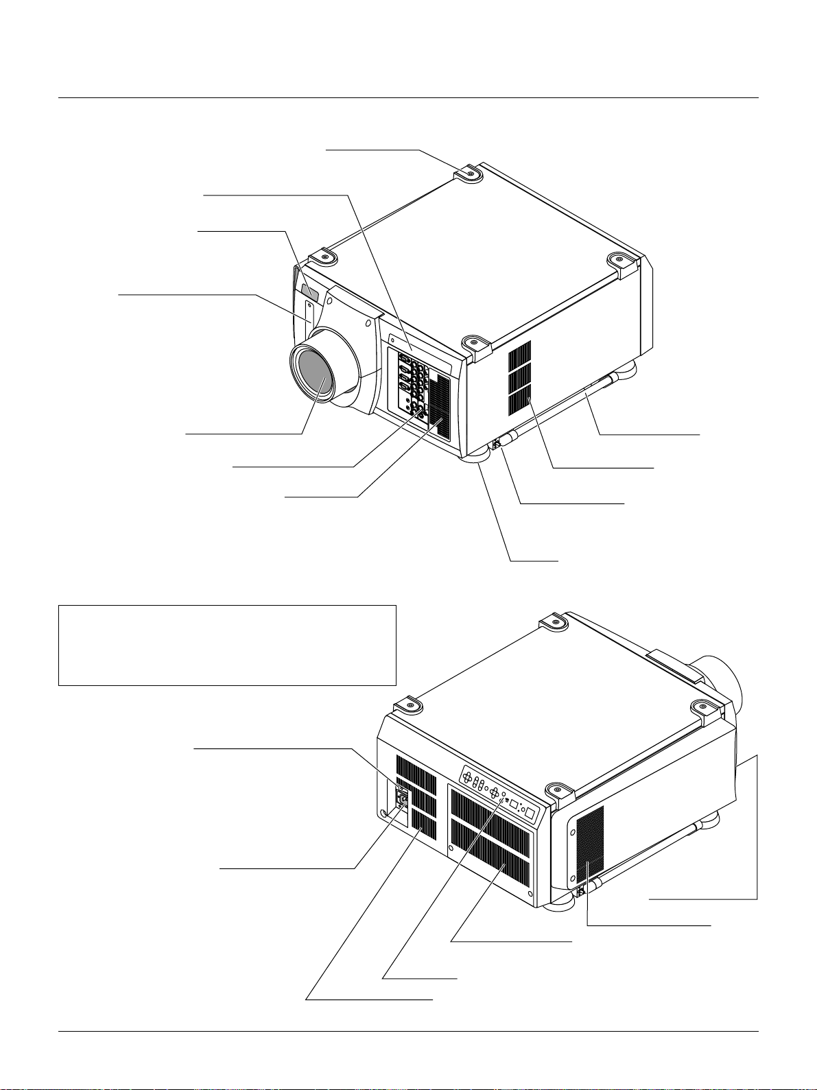
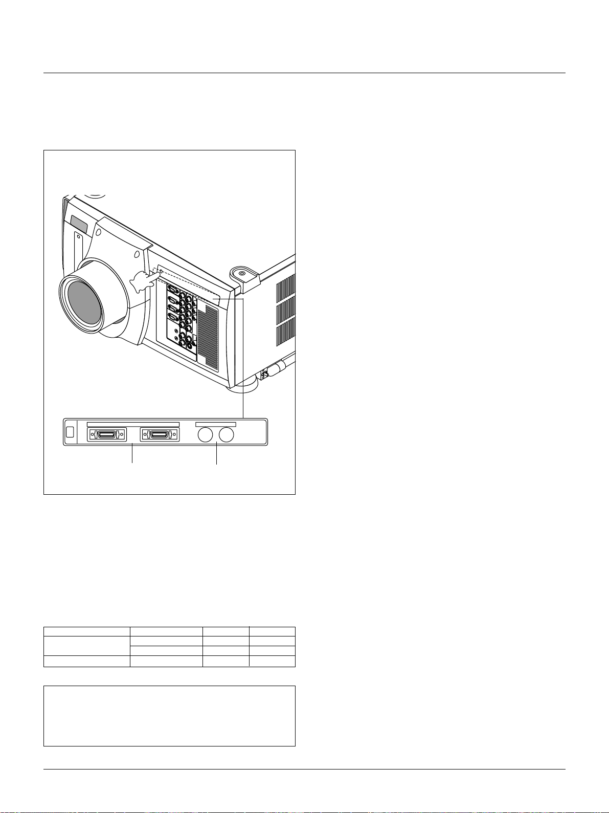
1. Part Names and Functions
Stacking Pad (4 pcs)
Digital Input Terminal Panel
Remote Sensor
PC Card Slot
Insert a flash memory card
here to upgrade the projector
system software or copy data
Lens (Optional)
Input T erminal Panel
Ventilation (in)
* To turn on the main power to the projector, press the switch to the
ON position (I) and the POWER indicator on the rear panel will
turn amber in color.
Press to the OFF position (0) to turn the main power off.
NOTE: When turning of f the main po wer , first return the projector
to the standby condition by pressing the POWER OFF button on
the remote control or the POWER button on the rear panel and
then turn off the main POWER switch. These procedures are necessary to protect your projector and the connected equipment.
Power Switch (Main power)*
Carrying Handle
Ventilation (out)
Release Lever (both sides)
Foot
AC INPUT
Connect the supplied power
cord here (AC 100-120 /
200-240V).
Ventilation (in)
Ventilating duct (out)
Ventilation (out)
Ventilation (in)
Controls
E – 8
Page 9
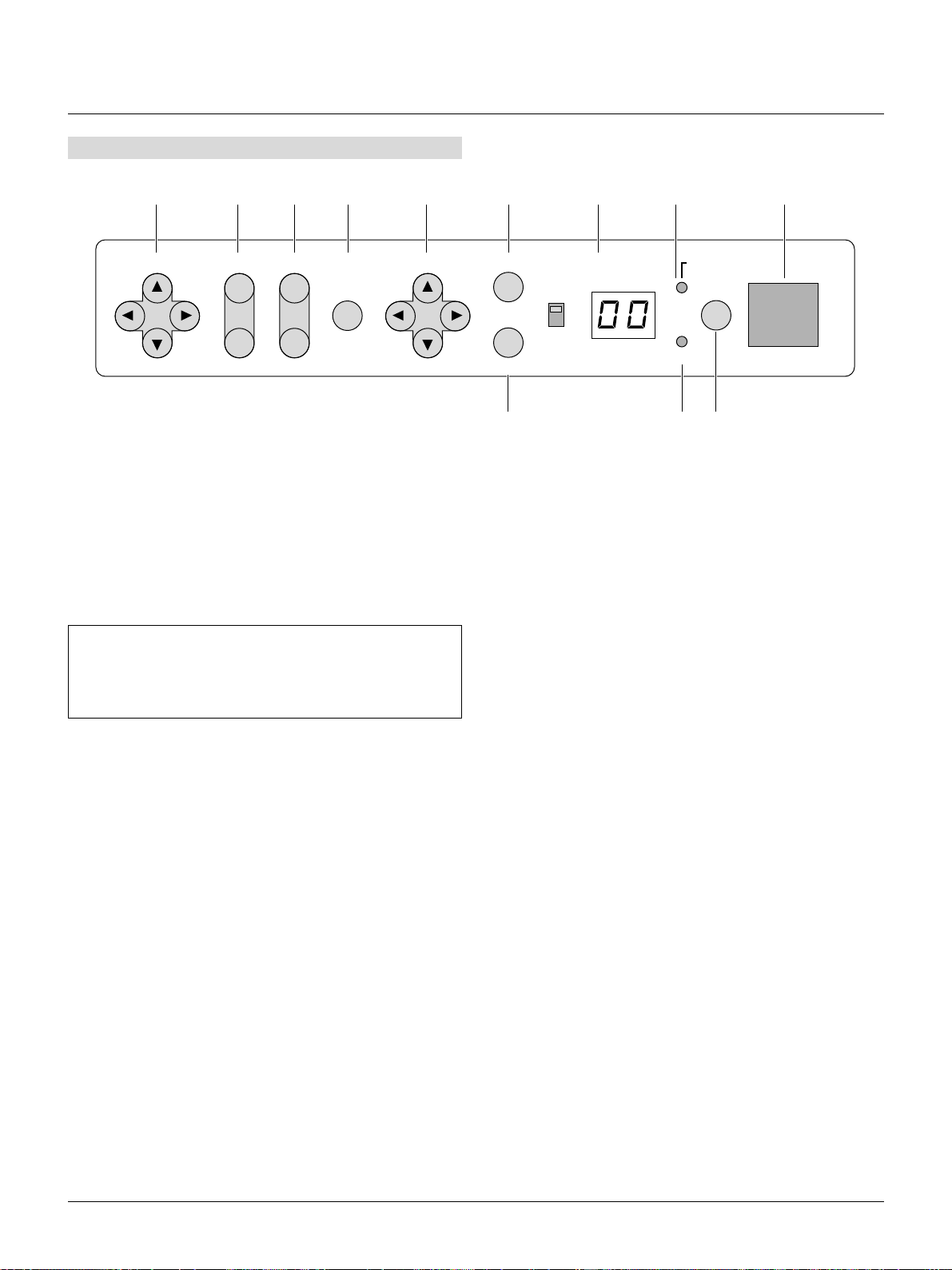
Controls
Remote sensor11 10 9 8 7 5 4 2
LENS SHIFT
FOCUS
ZOOM MENU SELECT
-
1. Power Button
Press to turn the projector on when the projector is in the standby
condition (Main Power switch must be on and the POWER indicator lit amber). Press and hold for 2 seconds to turn off the projector.
2. Power Indicator
When this indicator is green, the projector is on; when the indicator is amber, it is in standby mode.
NOTE: After the projector is turned of f, the indiacator "--" flashes
for three minutes to show that the cooling fan is working.
Do not turn off the main power during that time. After "--" stops
flashing, the POWER indicator will change to a steady amber glow
and the projector will be in the stand-by mode.
3 Status Indicator
When the projector is used with the ISS-6020 switcher on SW1
level or SW2 lev el mode, this indicator flashes when the projector
is not connected with the switcher correctly
or when the switcher is turned off.
4 Two Digit Display
INDICATOR: Displays projector error codes. The current projector ID(address) is displayed in normal operation.
ON/OFF Switch: Turns the INDICATOR on or off.
ENTER
INDICATOR POWER
ON
ON/OFF
+
OFF
CANCEL
STATUS
136
5 Enter Button
Executes your menu selection and activates items selected from
the menu. When the slidebar or dialog box is diplayed:
Pressing this button confirms adjustments/setting and returns to
the previous menu display.
6 Cancel Button
Press this button to exit the menu. Press this button to return the
adjustments to the last condition while you are in the adjustment
or setting menu.
7 Select (Up/Down/Left/Right) Button
Up/Down: Use these buttons to select the menu of the item you
wish to adjust.
Left/Right: Use these buttons to change the level of a selected menu
item.
8 Menu Button
Displays the main menu for operation.
9 Zoom Button
Zoom the lens in and out.
10 Focus Button
Adjust the lens focus.
11 Lens Shift Button
Adjust the lens offset by shifting the projected image position horizontally and vertically.
E – 9
Page 10
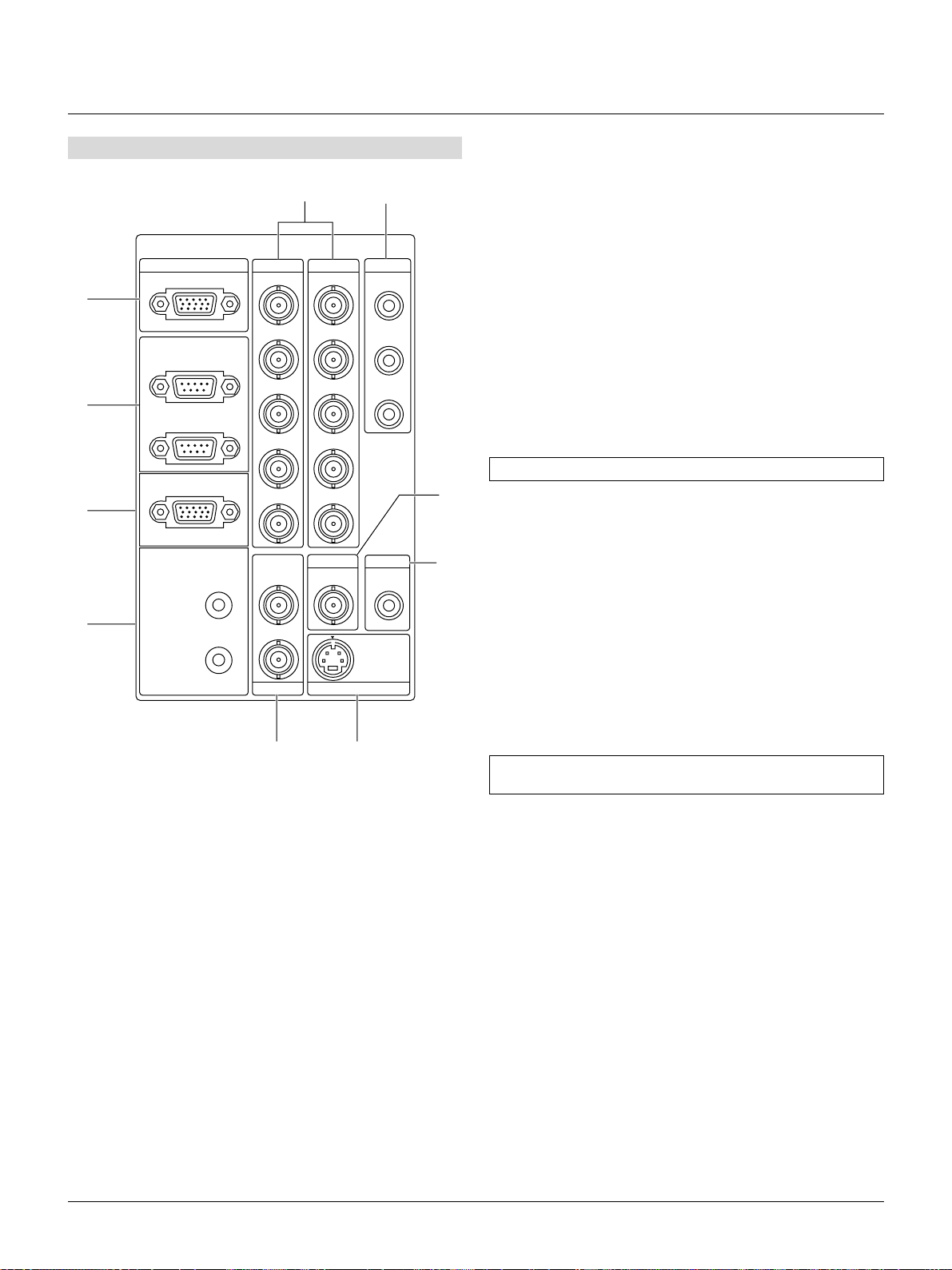
Terminal Panel
INPUT3
1
OPTION
2
REMOTE1
3
REMOTE2
4
RGB R/Cr
IN
OUT
OUT
INPUT2 INPUT1 INPUT4
G/Y
B/Cb
H/HV
V
S-VIDEO1
IN
Y
C
INPUT7 INPUT8
910
56
R/Cr Cr
G/Y
B/Cb Cb
H/HV
V
INPUT5
VIDEO1 VIDEO2
Y
INPUT6
S-VIDEO2
7
8
1 INPUT 3 RGB Connector (Mini D-Sub 15 pin)
Connect your PC or other analog RGB equipment such as a highdefinition document camera.
2 Option Connector (Mini D-Sub 9 pin)
For system expansion such as PC-control.
IN: connect to the external equipment such as PC.
OUT: for daisy-chaining multiple projectors and operating them
with the same external equipment. To do so, connect to a
second projector' s IN terminal to relay the input at the IN
terminal of the first projector until all the projectors are connected.
3 REMOTE 1 Connector (Mini D-Sub 15 pin)
This terminal allows external control of the projector from either
the Switcher or from an external control. When the
Switcher is used, connect to the REMOTE 1 terminal on the back
of the Switcher.
NOTE: This projector is compatible with the ISS-6020 Switcher.
4 REMOTE 2 Jacks
IN: wired remote control input.
OUT: for daisy-chaining multiple projectors and operating them
with the same remote control. T o do so, connect to a second
projector' s IN terminal to relay the input at the IN terminal
of the first projector until all the projectors are connected.
5 INPUT 1 and INPUT 2 Terminals (BNC)
Connect R,G,B,H (Horizontal sync) and V (Vertical sync) outputs
of the external equipment such as the Switcher. If using a component with a combined sync (SYNC) output, connect it to the H/V
terminal.
Also connect component video outputs (Y/Cb/Cr) of the external
equipment such as DVD player.
NOTE: The INPUT 2 terminal does not support SW1 Level and
SW2 Level modes for the ISS-6020 switcher.
6 INPUT 4 Cr/Y/Cb Terminal (RCA)
Connect component video outputs (Y/Cb/Cr) of the external equipment such as DVD player.
NOTE: This terminal accepts component signal only.
7 INPUT 5 VIDEO 1 Terminal (BNC)
Connect to the BNC video output of the external equipment such
as a VCR or laser disk player.
8 INPUT 6 VIDEO 2 Terminal (RCA)
Connect to the RCA video output of the external equipment such
as a VCR or laser disk player.
9 INPUT 7 S-VIDEO 1 Terminal (BNC)
Connect to the Y/C separate BNC video outputs of the external
equipment such as a VCR or laser disk player.
E – 10
Page 11
10 INPUT 8 S-VIDEO 2Terminal (Mini DIN 4 pin)
Connect to the S-video output of the external equipment such as a
VCR with an S-video output. This terminal allows switching between S2 and S1 VIDEO input modes. See the "S-Video Mode
Select" section for more information.
Push the left side of the panel to open the compartment for
the RGB Digital connectors and the optional SDI board.
OUTPUT OUTPUT
INPUT9 INPUT 0
RGB
DIGITAL
11
SDI
Space to install the optional
SDI board.
11 RGB Digital Input/Output Connectors (MDR 20 pin)
These connectors are used for double or triple stacking.
Use the supplied DFP cable to connect the OUTPUT terminal of
the first projector to the second projector's INPUT until all the projectors are connected. These connectors can also be used to accept
TMDS standard (Pannel Link) digital signal output from a digital
ready computer. In this case some graphics cards may cause flickering noise on the screen.
List of Recommended Graphics Cards
Manufacturer Product Card I/F Connector
I-O Data Devices, Inc. GA-SS21P8/PCI PCI DFP 20P
A TI Technologies, Inc. Expert LCD AGP DFP 20P
As of October 31, 1999
NOTE:
* These connectors support a maximum resolution of 1024768
(XGA).
* A DFP cable must be 5 m (16.4 feet) or less in length.
* Contact your dealer for installing the optional SDI board.
GA-SM02P2/CB PCMCIA DFP 20P
E – 11
Page 12
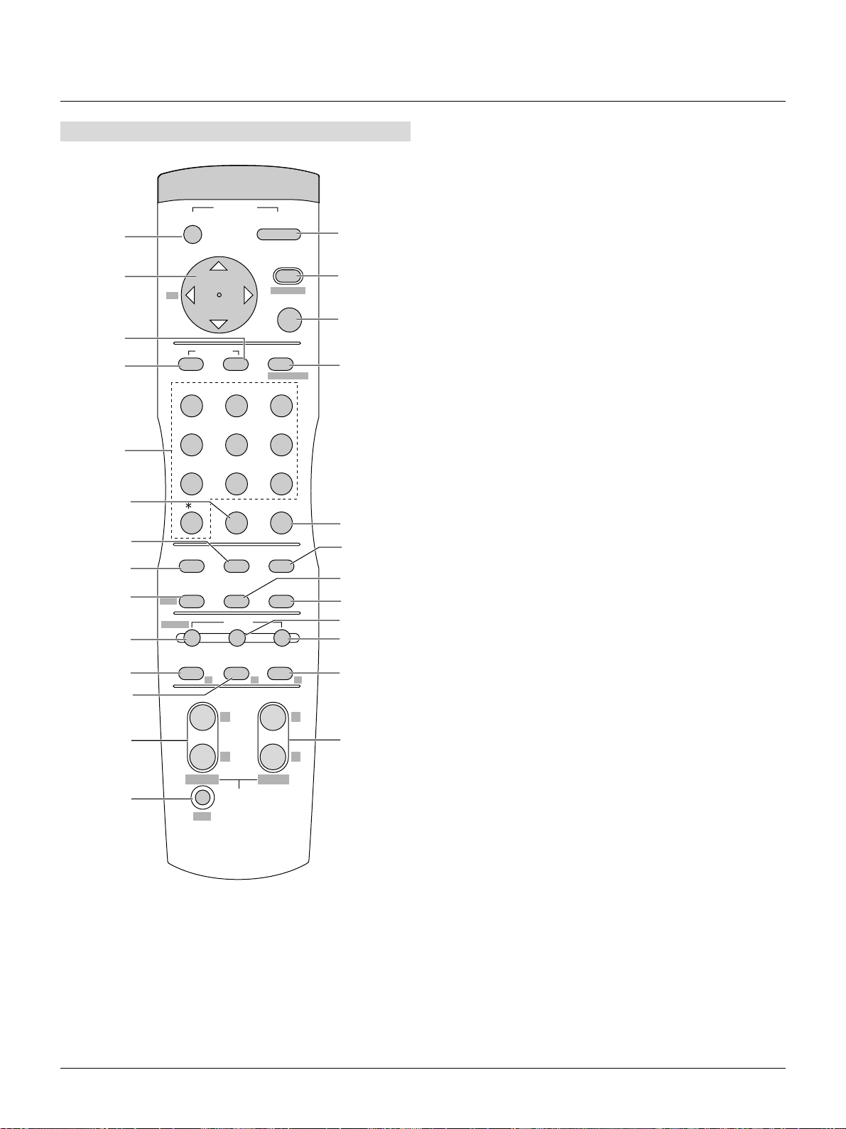
Remote Control
3 MENU
Press to display the main menu.
While pressing and holding CTL, press this button to display the
Remote Control ID dialog box to specify the remote control ID.
POWER
OFF
2
5
BS
-
ON
1
MENU
3
ADDRESS
+
ENTER
4
6
ADJUST
7
PICTURE
WHITE BAL.
ABC DEF
IMAGE
PROJECTOR
GHI
8
123
JKL MNO PQR
9
10
12
13
17
20
21
22
24
26
1 POWER ON
Press to turn on the projector. The PO WER indicator lights up green.
2 POWER OFF
Press and hold this button for a minimum of two seconds to turn
off the projector.
456
7
,.
VWX YZ?
8
UNDO CANCEL
9
STU
0
TEST
POSITION AUTOPIXEL
LENS
SHUTTER
PICTURE
KEYSTONE AMPLITUDE ENTRYLIST
MUTE
SOUND OSD
R G B
+
-
FOCUS ZOOM
CTL
PEMOTE CONTROLLER
RD-364E
HELPINFO.
MAGNIFY
LENS
11
14
15
16
18
19
23
+
25
-
4 ENTER
Executes the menu selection and activates items selected from the
menu. When the slidebar or dialog box is diplayed:
Pressing this button confirms adjustments/setting and returns to
the previous menu display.
5 CURSOR (Up/Down/Left/Right)
When pressed together, the CTL and buttons work as a Back
Space key in the entry screen.
Pressing and holding CTL, then this button moves the menu,
slidebar or dialog box.
6 ADJUST WHITE BAL
Press to display the Color adjustment screen. Pressing this button
sequentially selects "Color Temperature" → "White
Balance"→"Switcher RGB Gain"→"Ref.White Bal".
7 ADJUST PICTURE
Press to display the Picture adjustment screen. Pressing this button
sequentially selects "Brightness" → "Contrast" → "Color" → "Hue"
→ "Sharpness" → "V-Aperture".
8 IMAGE/PROJECTOR
Press to display the Image Option screen. Pressing this button sequentially selects "Image Mode" → "Video Mode" → "Signal
Level"
While pressing and holding CTL, pressing this button rotates
"Timer" → "Menu" → "Setup" → "Link Mode" → "Switcher Con-
trol" → "External Control" → "Passcode".
9 INPUT
Use to select an input, to name a signal, or to enter a passcode
during input registration.
1--INPUT 1 for RGBHV/Y, Cb/Pb, Cr/Pr
2--INPUT 2 for RGBHV/Y, Cb/Pb, Cr/Pr
3--INPUT 3 for RGB
4--INPUT 4 for Y, Cb/Pb, Cr/Pr
5--INPUT 5 for VIDEO 1
6--INPUT 6 for VIDEO 2
7--INPUT 7 for S-VIDEO 1
8--INPUT 8 for S-VIDEO 2
9--INPUT 9 for RGB DIGITAL (Panel Link) input
0--INPUT 0 for SDI input on the optional SDI board
10 UNDO
Press to return the adjustments and settings to the previous condition. While pressing and holding CTL, pressing this button clears
all the menus or ajustment/setting screen. At this time the adjustments/settings are stored in memory.
11 CANCEL
Press to exit the menu.
Press this button with CTL to return to the previous menu while
the menus appear. This feature allows you to adjust several items
concurrently.
E – 12
Page 13
12 INFO
Displays the "Source Information" or "Projector Information" window. This button toggles between these two windows.
13 TEST
Press to display the test pattern. Pressing this button sequentially
selects nine test patterns.
26 CTL
Used in conjunction with other buttons, similar to a shift key on a
computer.
27 Infrared Transmitter
Direct the remote control toward the remote sensor on the projector cabinet.
14 HELP
Provides online help.
15 PIXEL
Displays the Pixel Adjust screen to adjust the clock and phase.
16 AUTO
Press to adjust Position-H/V and Pixel Clock/Phase for an optimal
picture.
17 POSITION
Press to display the Blanking screen; press again to display the
Position screen.
While pressing and holding CTL, pressing this button displays the
Lens Shift adjustment screen.
18 MUTE SOUND
(available only when using with the ISS -6020 or IPS4000)
Turns off the sound for a short period of time. Press again to restore the sound.
19 MUTE OSD
Press to turn off the on-screen display. Press again to restore the
on-screen display.
NOTE: Y ou can also turn off the on-screen display by pressing and
holding CTL and then pressing MUTE OSD; doing this again restores it. In this case any adjustment will still change the projector's
memory settings. This mode is available even when an input is
switched to another or the power is turned off using the POWER
OFF button on the remote control.
20 MUTE PICTURE
Press to turn off the picture for a short period of time. Press again
to restore the picture. Pressing and holding CTL, then pressing this
button shuts off the light completely.
28 Remote Jack
Connect your remote control cable here for wired operation.
Remote Control Precautions
• Use the remote control within a distance of about 7m (23feet) and
at an angle of 30˚ above, below, to the left and to the right of the
remote control sensor located at the front of the main unit.
• The remote control system may not function when direct sunlight
or strong illumination strikes the remote control sensor of the main
unit, or when there is an obstacle in the path.
• When remote control buttons are pressed and held, main unit function keys may not operate.
• Do not subject to strong shock.
• Do not allow water or other liquid to splash on the remote control.
If the remote control gets wet, wipe it dry immediately.
• Avoid exposure to heat and steam.
• Remove the batteries from the remote control when the remote con-
trol is not going to be used for a long period.
You cannot operate the projector using the remote control if:
• the remote ID is not set to [00].
• the remote ID is not the same as the projector ID.
See page E-28 for setting remote ID and page E-40 for setting projector ID.
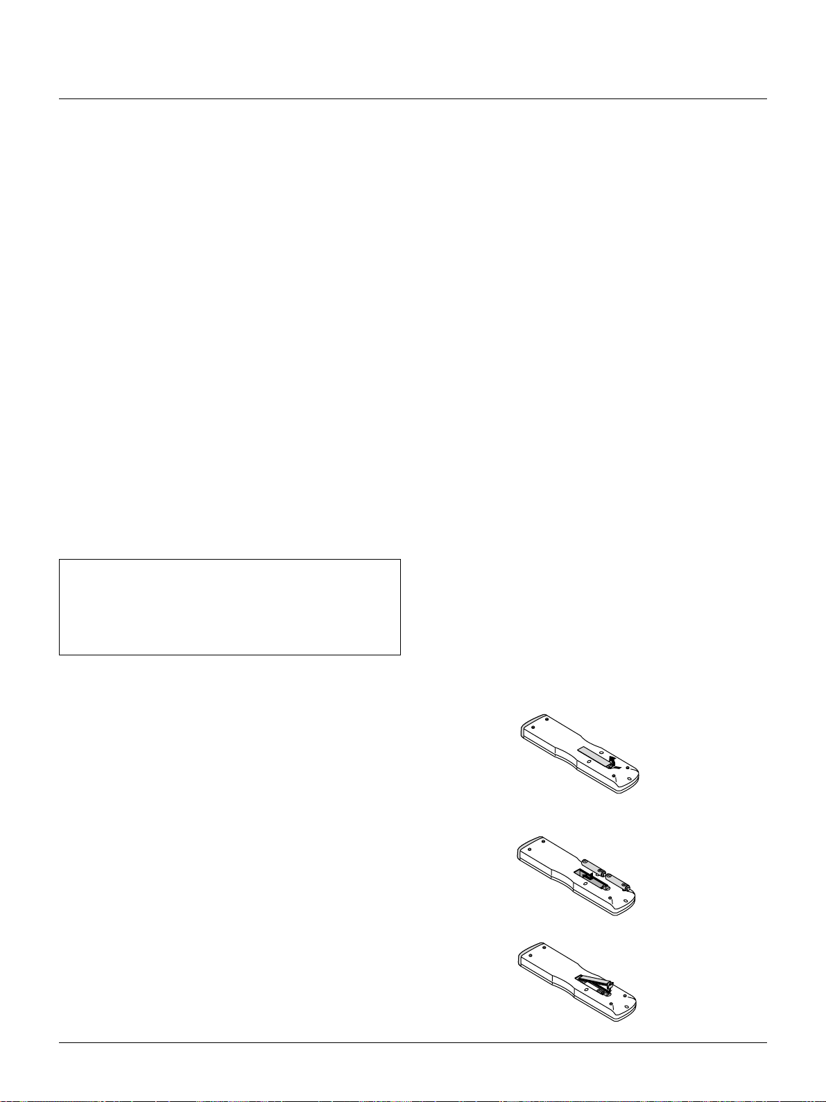
Remote Control Battery Installation
Installing the Remote Control Batteries
When it comes time to replace the batteries, two "AAA" type will be
required.
1. Press and open the cover.
21 KEYSTONE (R)
Press to display the Keystone Correction screen.
22 AMPLITUDE (G)
Service personnel only.
23 ENTRY LIST (B)
Press to display the Entry List screen.
24 FOCUS (+/–)
While pressing and holding CTL, pressing this button allows you
to adjust the lens focus.
25 MAGNIFY/ZOOM (+/–)
Magnify the size of a target portion.
While pressing and holding CTL, pressing this button allows you
to zoom the lens in and out.
2. Align and insert the batteries according to the (+) and (-) indica-
tions inside the case.
3. Replace the cover.
E – 13
Page 14

2. INSTALLATION
This section describes how to install the lens, set up the projector and
how to connect video and audio sources.
Optional Lens Installation
Four optional lenses are available: TL-08SF, TL-1Z, TL-2Z and TL4Z.
Preparation
* Turn the projector off, wait for the cooling fan to stop, then turn off
the main power switch on the rear panel.
Check that the projector has cooled off suff iciently before proceeding.
CAUTION
* The projector and lens contain high-precision parts. Do not induce
shock to the projector or the lens.
* Do not touch the lens surface. Doing so can degrade the optical
performance.
Installation Procedures
1. Remove the upper and the lower lens hood.
1) Remove the protective sponge.
3) Lift up the lower lens hood by 1 cm to release the hook. Remove the lower lens hood.
Hook
2. Attach the lens unit.
1) Remove the lens cap from the rear.
2) Remove the two screws. Push down on the lower lens hood
then lift up and pull off the upper lens hood.
2) Insert the lens so that the three pins on the lens unit are properly lined up with the holes on the projector.
Fixed pin
NOTE: Do not remove the front lens cap during lens installation.
The lens cap helps minimize any marring of the front lens element.
E – 14
Page 15
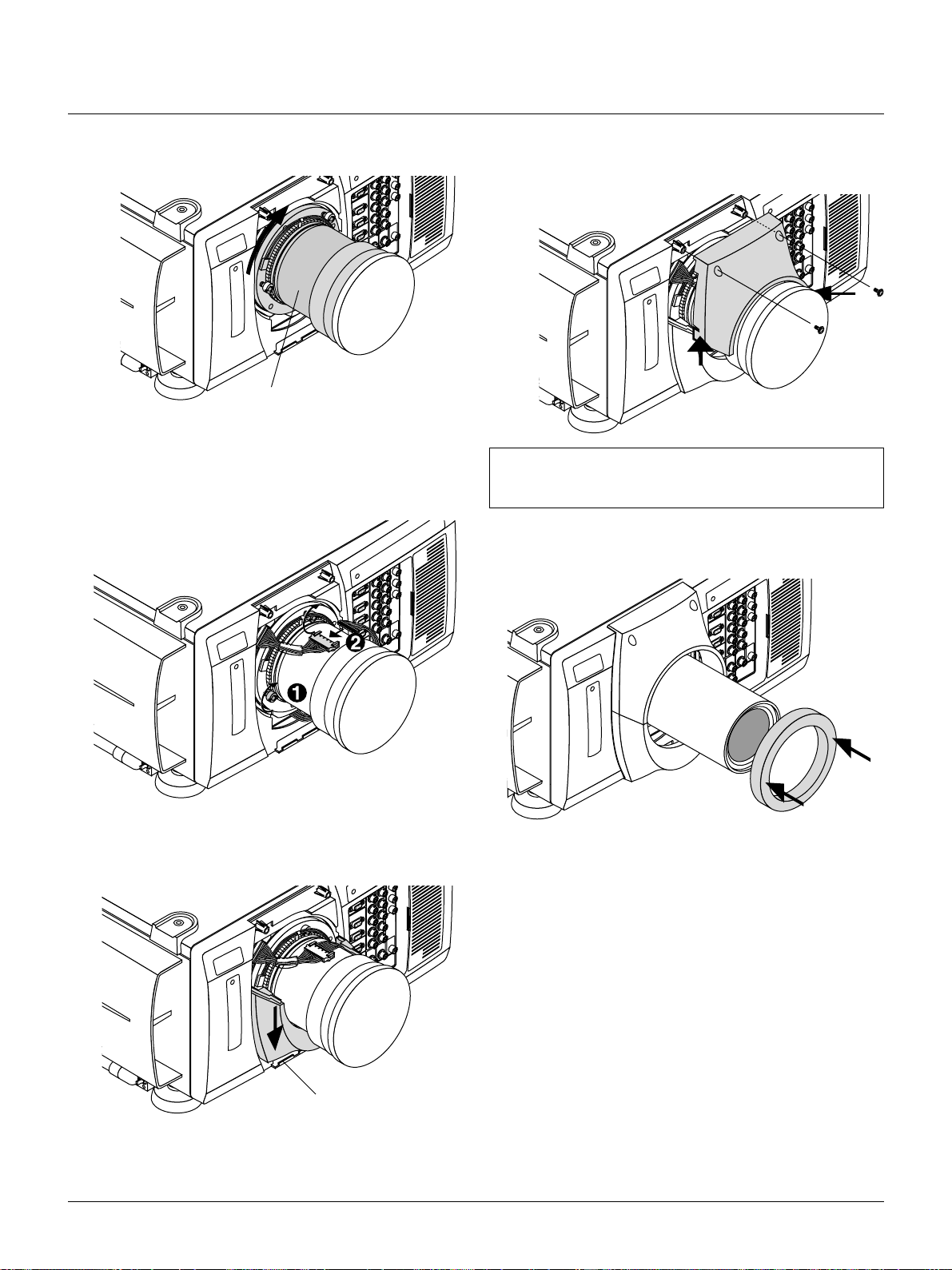
3) Rotate the lens barrel clockwise to fix the lens unit.
Lens barrel
3. Secure the fixed screws and connect the extension cable attached
to the projector.
1) Secure the three screws on the lens holder.
2) Insert the connector of the lens unit into the socket of the extension cable attached to the projector.
2) Insert the upper lens hood while pushing the left and right
bottom. Secure the two screws.
NOTE: This completes installation for the optional lens TL-08SF
and TL-1Z. For TL-2Z and TL-4Z, attach the supplied dust cap as
shown on the next step.
5. Attach the dust cap.
4. Reattach the lens hood.
1) Insert the lower lens hood into the hook.
Hook
E – 15
Page 16

Setting Up The projector
To set up and use the projector, you must first do:
1. Determine the screen size and the optional lens to be used.
NOTE: Refer to page E-14 for lens installation.
2. Set up a screen or select a non-glossy white wall onto which you
can project your image.
Moving The Projector
Always carry your projector by the handle. Ensure that the power cord
and any other cables connecting to video sources are disconnected
before moving the projector . When mo ving the projector or when it is
not in use, cover the lens with the lens cap.
Pulling Out the Handles
Pull out the handle until it clicks into place.
Selecting A Location The further your projector is from the screen or
wall, the larger the image. The minimum size the image can be projected is 80" (2 m) measured diagonally. The largest the image can be
is 500" (12.7 m).
500"
400"
300"
200"
100"
80"
WARNING
• Only use your projector on a solid, level surface. If the projector
falls to the ground, you can be injured and the projector severely
damaged.
• Do not use the projector where temperatures vary greatly. The projector must be used at temperatures between 40 degrees F (5 degree
C) and 95 degrees F (35 degree C).
• Do not expose the projector to moisture, dust, or smoke. This will
degrade the screen image.
• Ensure that you have adequate ventilation around your projector
for proper heat dissipation. Do not cover the vents on the projector
cabinet.
Retracting the Handles
1) Push the lever to unlock and 2) retract the handle.
E – 16
Page 17

Attaching the Power Cable Stopper
The Power cable stopper is provided with the projector so that the
cable cannot be accidentally unplugged from the AC IN.
1) Remove two screws.
These screws are used later again.
2) Plug the power cable into the AC IN and then attach the stopper.
Power cable
O
F
F
P
O
W
E
R
O
N
3) Fix the stopper using the two screws.
Stopper
E – 17
Page 18
Screen Size and Projection Distance
0.23H
0.3H
0.5V
0.32V
Screen Width (H)
Screen Height (V)
Normal Projection Position
LENS SHIFT
1. Place your projector on a flat level surface at the optimal distance
from the screen. (Avoid having bright room lighting or sun light
directly on the screen or projection surface.)
2. Connect the power cable, remove the lens cap and turn the projector on. (If no input signal is available, the projector will display a
black screen.)
3. Ensure that the projector is square to the screen.
4. Move the projector left or right to center the image horizontally
on the screen.
5. To move the projected image up or down, adjust the Lens Shift
Control.
6. Adjust the focus and the zoom.
NOTE:
1: When using the zoom lens, it is recommended that the projector
is positioned at an angle of from -15 to +15 degrees from the horizontal.
2: While projecting an image with lower resolution than the
projector's native resolution (1024768), if you want to enlarge
the image to fill the screen in the Native mode, proceed as follo ws:
1. Tturn on the “Native with Zoom” on the Resolution window.
See page E-34.
2. Press ENTER to close the window.
3. While pressing and holding CTL, press MAGNIFY or FOCUS
on the remote control to zoom the lens in or adjust the lens
focus.
Shutter mechanism
The XT5000 projector is equipped with "Shutter" feature, which allows the user to shut off the light completely on the screen. To use the
shutter function, hold down the CTL button, and press the MUTE
PICTURE button on the remote control.
Projection Distance and Screen Size
Lens
Model
Magnification
Screen Size (Diagonal) / Projection Distance
80"
100"
200"
300"
400"
500"
TL-08SF
0.84
1.4
(4.48)
1.7
(5.60)
3.4
(11.20)
5.1
(16.80)
6.8
(22.40)
8.5
(28.00)
* The values for projection distance are estimated.
TL-1Z
1.5-2.5
2.5-4.0
(8.00-13.33)
3.1-5.0
(10.00-16.66)
6.1-10.1
(20.00-33.33)
9.2-15.2
(30.00-50.00)
12.2-20.3
(40.00-66.66)
15.2-25.4
(50.00-83.33)
(13.34-21.33)
(16.67-26.66)
(33.34-53.33)
(50.00-80.00)
(66.67-106.66)
(83.34-133.33)
TL-2Z
2.5-4.0
4.1-6.5
5.1-8.1
10.2-16.2
15.3-24.3
20.4-35.5
25.4-40.6
Unit: m (feet)
TL-4Z
4.0-7.0
6.6-11.3
(21.34-37.33)
8.2-14.2
(26.67-46.66)
16.3-28.4
(53.34-93.33)
24.4-42.6
(80.00-140.00)
32.6-56.8
(106.67-186.66)
40.7-71.1
(133.34-233.33)
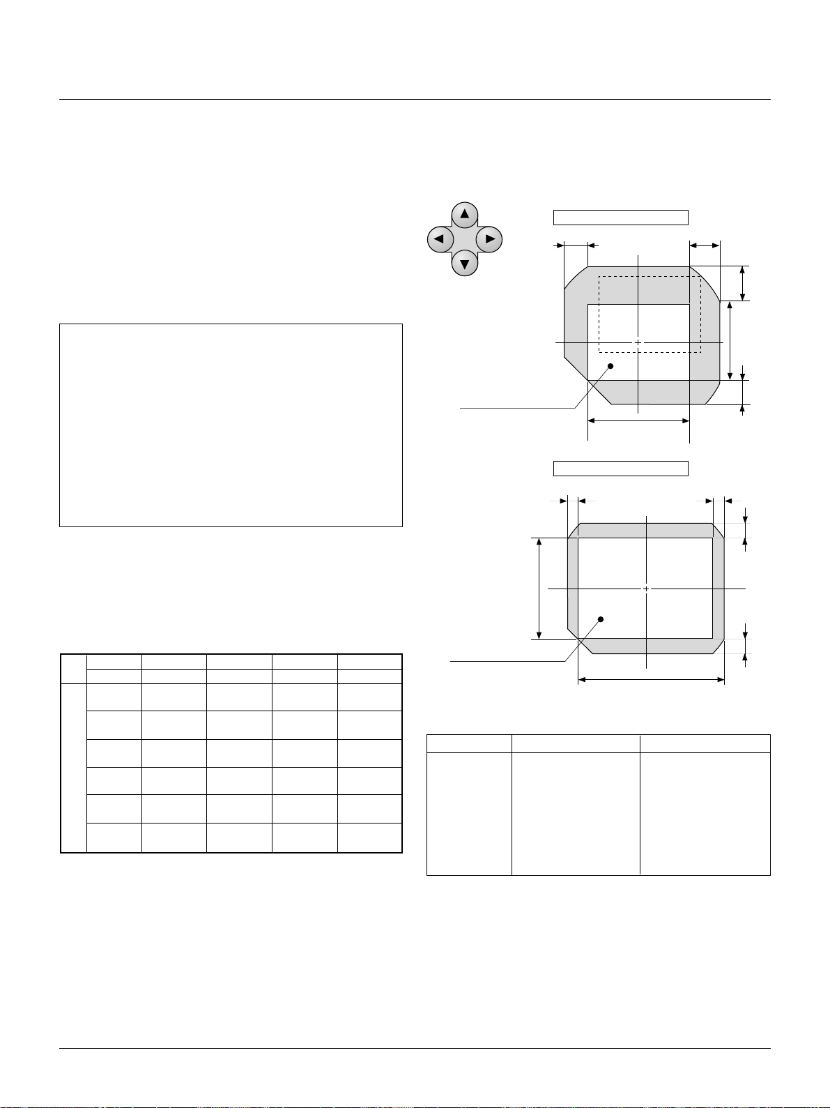
Lens Shift Adjustable Range
Lens can be shifted within the shaded area as shown below using the
normal projection position as a starting point.
(H: width of projected image, V: height of projected image)
For TL-1Z, TL-2Z, TL-4Z
For TL-08SF
0.08H
Screen Height (V)
Normal Projection Position
Screen Width (H)
Screen Size H V
80" 1.6 (39.37) 1.2 (47.24)
100" 2.0 (78.74) 1.5 (59.06)
150" 3.0 (118.11) 2.3 (90.55)
200" 4.0 (157.48) 3.0 (118.11)
300" 6.1 (240.16) 4.6 (181.102)
400" 8.1 (318.9) 6.1 (240.16)
500" 10.2 (401.58) 7.6 (299.21)
0.08H
Unit: m (inch)
0.15V
0.15V
E – 18
Page 19

Top View
Screen
Side View
Normal projection
Lens shifted
Reflecting The Image
Using a mirror to reflect your projector's image enables you to enjoy
a much larger image in a much smaller space. Contact your dealer if
you need a mirror.
If you're using a mirror and your image is inverted, use the [Main
Menu] → [Projector Options] → [Setup] → [Orientation] to select
the correct orientation.
(See page E-39.)
Rear Screen Projection
You can use your XT5000 to project an image from the rear onto a
transparent screen. The projection distance is the same for both rear
and front projection. Contact your dealer if you need a transparent
screen.
If you're projecting the image from the rear and your image is inverted, use the [Main Menu] → [Projector Options] → [Setup] →
[Orientation] to access to correct the orientation. (See page E-39.)
Screen
Lens shifted
Normal projection
Stack Projection (up to three units)
The MultiSync XT5000 can be stacked without any additional framing (gravity stacking). One unit can be stacked on top of the other up
to three units.
Make sure that each foot is securely seated on the stacking pad.
NOTE: See next page for more details.
Screen center
E – 19
Page 20

Setting up for Double or Triple Stacking in Link
Mode
OUTPUT
OUTPUT
Master projector
INPUT3
RGB R/Cr
OPTION
IN
OUT
REMOTE1
INPUT2 INPUT1 INPUT4
R/Cr Cr
G/Y
G/Y
Y
B/Cb
B/Cb Cb
H/HV
H/HV
V
V
INPUT9
INPUT9
OUTPUT OUTPUT
INPUT9 INPUT 0
RGB
DIGITAL
DFP cable (supplied)
OUTPUT OUTPUT
INPUT9 INPUT 0
RGB
DIGITAL
DFP cable (supplied)
OUTPUT OUTPUT
INPUT9 INPUT 0
RGB
DIGITAL
Slave projector
SDI
SDI
SDI
bi-directional RS232C cable
(not supplied)
INPUT3
RGB R/Cr
OPTION
IN
OUT
REMOTE1
INPUT3
RGB R/Cr
OPTION
IN
OUT
REMOTE1
INPUT2 INPUT1 INPUT4
R/Cr Cr
G/Y
G/Y
Y
B/Cb
B/Cb Cb
H/HV
H/HV
V
V
INPUT2 INPUT1 INPUT4
R/Cr Cr
G/Y
G/Y
Y
B/Cb
B/Cb Cb
H/HV
H/HV
V
V
NOTE: SW 1 Level and SW 2 Level of Switcher Control are not available on Link Mode.
For double or triple stacking, follow the instructions described belo w .
2-2. Next, using a commercially available, bi-directional RS-232C
cable connect the OPTION OUT terminal of the master pro-
1) Stacking the Projectors
1-1. Place the projectors at the proper height for best screen to
projector relationship. Make sure that all projectors have the
same display orientation.
2) Hookup
2-1. Use the supplied DFP cable to connect the RGB DIGITAL
output (INPUT 9) of the master projector to the RGB DIGIT AL
input of the slave projector (the second and third stack) until
jector to the OPTION IN terminal of the slave projector(s) until
all the projectors are connected.
NOTE: When inputting signals other than those listed on page E44, use a commercially available distribution amplifier between
the projector and those signals because those signals are not compatible with this projector in the Digital Link mode.
2-3. Turn all the projectors on and roughly make some optical
adjustments to each projector.
all the projectors are connected.
E – 20
Page 21

3) Adjusting and registering signals to be projected
in Link mode and stack application.
Signal Data Preparation
3-1. Create data for the master projector and copy data to the
slave projectors.
3-1-1. Choose one projector as the master.
3-1-2. Turn the master projector on.
3-1-3. Display all desired input signals, make adjustment to each
signal, then save all adjustments on the master projector. (Ad-
justments will be saved automatically.)
3-1-4. Turn the master projector off (standby mode).
3-1-5. Store all the adjustments on a PC card from the master pro-
jector.
3-1-5-1Remove the PC Card slot decorative panel to access the
PC card slot. Insert a PC card into this slot.
3-1-5-2. Press and hold CANCEL, then press PO WER on the r ear
panel of the master projector.
The POWER indicator will change to steady green and the PC
Card Access indicator will start flashing. After storing data on
the PC card, the POWER indicator will change to amber.
3-1-5-3. Remove the PC card from the slot of the master projec-
tor.
3-1-6. Transfer the data to the other slave projectors using the PC
card so that all the projectors have the same data in memory.
3-1-6-1. Insert the PC card into the slot of a slave projector.
NOTE: Since data in the slave projectors will be lost at this time,
make backup copies of them before proceeding.
3-1-6-2. Press and hold ENTER, then press MENU on the rear
panel of the slave projector. The POWER indicator will c hange
to steady green and the PC Card Access indicator will start
flashing to indicate that the data is being copied from the PC
card to the slave pr ojector. After copying data to the slave projector, the POWER indicator will change to amber.
3-1-6-3. Remove the PC card fr om the slave pr ojector. (If you are
triple stacking the projector s, repeat steps fr om 3-1-6-1 for the
third projector.)
NOTE: Signal list for Video signals such as Video, S-Video and
Component video) that have been once changed to RGB (digital)
cannot be edited. See “Compatible Input Signal List” page E-44
for compatible signals.
4) Link Mode Setting
4-1 Assign a unique Projector ID for each projector.
4-1-1. Select [Main Menu] → [Projector Options] → [Setup]
→[Page 3] → [Projector ID]. See page E-40 for specifying ID.
4-1-2. Specify a unique projector ID for each projector.
4-2 Select the same communication speed for all the projec-
tors.
4-2-1. Select [Main Menu] → [Projector Options] → [Setup]
→[Page 4] → [Speed]. See page E-40 for setting the communi-
cation speed.
4-2-2. Select the appropriate speed between 4800 and 38400.
4-3 Set the Link Mode on each projector.
4-3-1. Select [Main Menu] → [Projector Options] → [Link Mode].
4-3-2. Select [Slave] on the slave projector(s).
4-3-3. Select [Master] on the master projectors. See page E-40 for
setting Link Mode.
4-4 Project a source image from all projectors
4-4-1. Display any signal onto the screen.
4-4-2. Check to see if the imags on the master projector are dis-
played in syncronization with the ones on the other slave projectors while the projectors are in link mode.
4-5 Make adjustments to the slave projector(s).
NOTE: See "7. List of Menu Items Available on Link Mode" on
page E-45 for more information.
4-5-1. Temporarily, change the master projector from Master to
Standalone. Make sure that the slave projectors are still in Slave
mode.
4-5-2. Display a source you want to adjust from the master projec-
tor.
4-5-3. On the Slave Projector(s) select the same signal From the
Entry List (same No.) as that of the master projector. Display it
from the slave projectors.
4-5-4. Adjust Blanking and Position to match the image of the mas-
ter projector. See page E-34 for Blanking and Position adjustment.
4-5-5. Make Picture adjustment such as brightness, contrast, or color
temperature.
4-5-6. Change the master projector from Standalone to Master to
activate the Link Mode
4-6 Display the desired source. This completes the Link Mode
adjustment procedure.
4-7 Display the internal crosshatch test pattern.
NOTE: Use a different single color for each projector. Example:
4-8 Tur n on Green of one projector (master), then Red of an-
other (slave 1) and Blue of the other (slave 2).
5) Adjusting the lens shift, zoom and focus to
clearly display all three projected patterns.
5-1. Adjust the Lens Shift using the LENS SHIFT b utton on the
rear panel. You can also adjust the Lens Shift by pressing
and holding CTL and pressing the POSITION button on the
remote control. For Lens Shift Adjustable Range, see page
E-18.
5-2. Zoom the lens in and out by using the ZOOM button on the
rear panel or the remote control.
5-3. Adjust the lens focus by using the FOCUS button on the
rear panel or the remote control.
NOTE: If the physical (vertical) alignment of the projector(s) is/
are not correct, adjust the height of the feet. If there is any keystone distortion, use Keystone adjustment to correct and save the
settings on each projector. See page E-35 and E-39 for Keystone
correction.
This completes set-up and adjustments. An image is projected from
the master projector. See page E-40 for Link mode.
E – 21
Page 22

3. CONNECTIONS
When used in standalone operation
Connecting Your PC Or Macintosh Computer
Connecting your PC or Macintosh computer to XT5000 Projector will
enable you to project your computer's screen image for an impressive
presentation.
To connect to a PC or Macintosh :
1. Turn off the power to your projector and computer.
2. Use a signal cable (not provided) to connect your PC or Macintosh
computer to the projector.
3. Turn on the projector and the computer.
4. If the projector goes blank after a period of inactivity, it may be
caused by a screen saver installed on the computer.
Connecting Your Document Camera
You can connect the projector to a document camera. To do so, simply:
1. Turn off the power to your projector and document camera.
2. Use a standard video cable to connect your document camera to
the V ideo input on your projector . Or connect to the INPUT3 (RGB)
on your projector.
3. Turn on the projector and the document camera.
NOTE: Refer to your document camera's owner's manual for more
information about your camera's video output requirements .
Connecting Your VCR Or Laser Disc Player
Use common RCA cables (not provided) to connect your VCR or laser disc player to your MultiSync XT5000 Projector. To make these
connections, simply:
1. Turn off the power to your projector and VCR or laser disc player.
2. Connect one end of your RCA cable to the video output connector
on the back of your VCR or laser disc player, connect the other
end to the V ideo input on your projector . Use standard RCA audio
patch cords to connect the audio from your VCR or laser disc
player to your projector (if your VCR or laser disc player has this
capability). Be careful to keep your right and left channel connections correct for stereo sound.
3. Turn on the projector and the VCR or laser disc player.
NOTE: Refer to your VCR or laser disc player o wner's manual for
more information about your equipment's video output requirements.
PC
PC control
ISS-6020 Switcher
Wired remote control
Document camera
INPUT3
RGB R/Cr
OPTION
IN
OUT
REMOTE1
REMOTE2
IN
OUT
E – 22
INPUT2 INPUT1 INPUT4
R/Cr Cr
G/Y
G/Y
B/Cb
B/Cb Cb
H/HV
H/HV
V
V
INPUT6
INPUT5
S-VIDEO1
VIDEO1 VIDEO2
Y
C
S-VIDEO2
INPUT7 INPUT8
Document camera
Y
DVD player
PC / Workstation
DVD player VCR
LD player
Page 23

When Used with One Switcher (ISS-6020/ISS-6020G)
Up to 10 input signals can be accepted when the projector is connected to one Switcher. Using the projector with the Switcher allows easy
adjustment and signal selection.
To REMOTE1
Optional control cable 15p-15p
(CTL-6010)
INPUT3
RGB R/Cr
OPTION
IN
OUT
REMOTE1
REMOTE2
IN
OUT
INPUT2 INPUT1 INPUT4
S-VIDEO1
INPUT7 INPUT8
G/Y
B/Cb
H/HV
V
Y
C
R/Cr Cr
G/Y
B/Cb Cb
H/HV
V
INPUT5
INPUT6
VIDEO1 VIDEO2
S-VIDEO2
Y
To INPUT 1
3BNC-3BNC cable(sync on green)
4BNC-4BNC cable(composite)
5BNC-5BNC coaxial cable
(separate sync)
(recommended)
To SYSTEM CONTROL
REMOTE 1
From R, G, B, H/V on separate H and
V. on the RGB OUTPUT module
The Switcher
ISS-6020/ISS-6020G
VCR
Personal computer
• Select [Main Menu] → [Projector Options] → [Switcher Control] → [SW1 Level]. See page E-40 for the information in detail.
• For more information on the Switcher, refer to the user’s manual accompanying the ISS-6020/ISS-6020G Switcher.
• All cables mentioned above are optional.
E – 23
Page 24

When Used with Two or More Switchers (100 Inputs)
Up to 100 inputs can be accepted using the NEC ISS-6020 Switcher.
How to make connections:
1 Connect the REMOTE 1 terminal of the master Switcher to the
REMOTE 1 of the projector using the optional control cable (15p15p/CTL-6010).
2 Next connect the REMOTE 2 terminal of the master Switcher to
the REMOTE 1 terminal of the first sla ve Switcher using the same
optional control cable as mentioned above. Third, connect the
REMOTE 2 terminal of the first slave to the REMOTE 1 of the
second slave, and the REMO TE 2 terminal of the second slave to
the REMOTE 1 terminal of the third slav e (— and the REMOTE
2 of the ninth slave to the REMO TE 1 of the tenth slave). Connect
all the Switchers with optional control cables.
• Select [Main Menu] → [Projector Options] → [Switcher Control]
→ [SW2 Level]. See page E-40 for the information in detail.
• Refer to the user’s manual accompanying the Switcher.
• Cables mentioned are not included with the projector.
Signal
10 inputs
Switcher
SLAVE 1
Signal
REMOTE 1
REMOTE 2
NOTE:
• Be sure to set all the slide switches (S8603) of the Switcher to
RS-422 positions. Set the one on the last slave Switcher to the
appropriate position to match the connected equipment such as
a personal computer. (RS-422/RS-232C for PC control of projector)
• Set the DIP switch S8601 of the Switcher.
OPTION (PC)
REMOTE
CONTROL
10 inputs
10 inputs
SLAVE 2
SLAVE 3
SLAVE 9
SLAVE 10
Signal
REMOTE 1
REMOTE 2
REMOTE 1
REMOTE 2
Signal
REMOTE 1
REMOTE 2
To SLOT 1
To SLOT 2
To SLOT 10
MASTER
SWITCHER
Signal (Input 1)
REMOTE
To REMOTE 2
REMOTE 1
Projector
OPTION
(PC)
NOTE: The optional remote control RC-6320 for ISS-6020 will
not work correctly in the SW Level 1 or 2 mode.
E – 24
Page 25

Set the DIP switch (S8601) of the Switcher as follows:
NOTE: Slave numbers 1 to 10 must correspond to the master’s slot numbers 1 to 10.
ISS-6020
ISS-6020G
Master
Slave 1
Slave 2
Slave 3
Slave 4
Slave 5
Output to
The Projector
Slot 1 of the Master
Slot 2 of the Master
Slot 3 of the Master
Slot 4 of the Master
Slot 5 of the Master
Setting of S8601
OPEN
1 2 3 4 5 6 7 8
OPEN
1 2 3 4 5 6 7 8
OPEN
1 2 3 4 5 6 7 8
OPEN
1 2 3 4 5 6 7 8
OPEN
1 2 3 4 5 6 7 8
OPEN
1 2 3 4 5 6 7 8
Slave 6
Slave 7
Slave 8
Slave 9
Slave 10
OPEN
Slot 6 of the Master
1 2 3 4 5 6 7 8
OPEN
Slot 7 of the Master
1 2 3 4 5 6 7 8
OPEN
Slot 8 of the Master
1 2 3 4 5 6 7 8
OPEN
Slot 9 of the Master
1 2 3 4 5 6 7 8
OPEN
Slot 10 of the Master
1 2 3 4 5 6 7 8
E – 25
Page 26
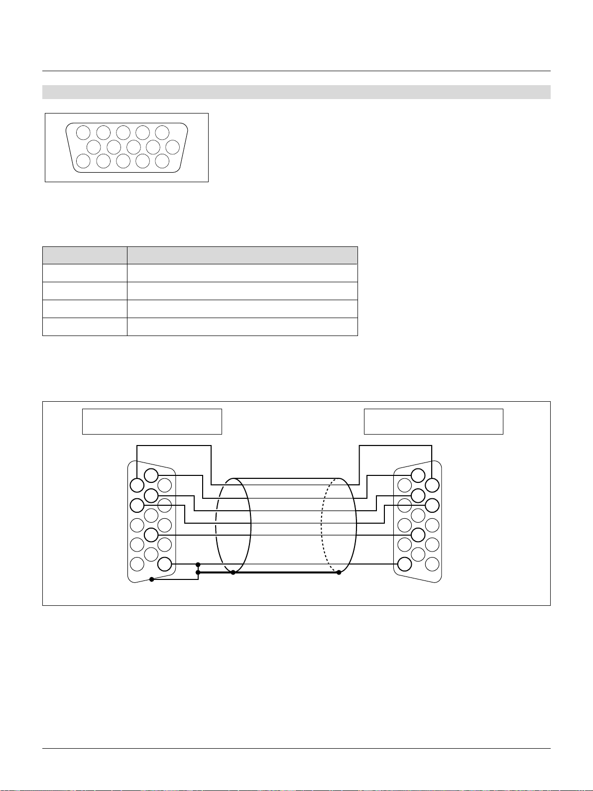
REMOTE 1 Connector
54321
109876
15 14 13 12 11
This connector is used for either connecting the ISS-6020/ISS-6020G Switcher or a third party external control device. When
the Switcher is used, connect it with the optional control cable (15-15 pin; 50 ft./16m; CTL-6010) to this connector.
When used with the Switcher.
Pin No. FUNCTION
1, 2, 6 and 7 Sending and receiving data when the Switcher is used.
9 Identifying the Projector
15 Ground
Others Used inside the Projector. Normally set to OPEN.
When using with the Switcher ISS-6020/ISS-6020G, connect no. 1,2,6,7,9 and15 pins of the projector to the same no. pins of
the switcher as shown below.
REMOTE 1 connector of the Projector
mini D-sub 15 pin (female)
6
1
7
2
9
15
Pins without a number are open.
Pin Configuration of Optional CTL-6010 Cable
REMOTE 1 connector of the Switcher
mini D-sub 15 pin (female)
Shield (frame ground)
6
1
7
2
9
15
E – 26
Page 27
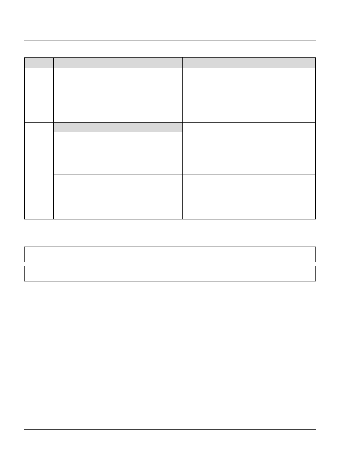
When used in stand alone operation.
Pin No.
14
5
10
4,8,12,11
11pin
OPEN
OPEN
OPEN
OPEN
OPEN
OPEN
OPEN
OPEN
SHORT
SHORT
SHORT/OPEN
SHORT
SHORT
SHORT
12pin
OPEN
OPEN
OPEN
OPEN
SHORT
SHORT
SHORT
SHORT
OPEN
OPEN
OPEN
OPEN
OPEN
8pin
OPEN
OPEN
SHORT
SHORT
OPEN
OPEN
SHORT
SHORT
OPEN
SHORT
4pin
OPEN
SHORT
OPEN
SHORT
OPEN
SHORT
OPEN
SHORT
OPEN
OPEN
FUNCTION
External control mode ON
External control mode OFF
POWER ON
POWER OFF
PICTURE MUTE ON
PICTURE MUTE OFF
RGB 1 (INPUT 1)
VIDEO 1 (INPUT 5)
S-VIDEO 1 (INPUT 7)
COMPONENT (INPUT 4)
SDI
RGB 2 (INPUT 2)
VIDEO 2 (INPUT 6)
S-VIDEO 2 (INPUT 8)
RGB (DIGITAL) (INPUT 9)
RGB 3 (INPUT 3)
* When the combinations other than specified in the above table are selected, the input will be forcefully switched to RGB 1.
* The term “SHORT” means to connect with pin 15
* When in the external control mode, the POWER, INPUT and PICTURE MUTE buttons on the remote control will not function.
NOTE: Pin 13 is the external remote signal terminal. The projector can be controlled by the same format signal as the supplied remote control
from the external controller regardless of setting on Pin 14.
NOTE: When turning off the power to the projector using the external control, do not disconnect the plug from the power outlet. These
procedures are to protect your projector and the connected equipment.
E – 27
Page 28

Operating Multiple Projector with Remote Control
IN
OUT
REMOTE 2
You can operate multiple projectors with the same remote control in wireless operation.
To do so:
1. Select [Main Menu]→[Projector Options]→[Setup]→[Page 3]→[Projector ID] and assign an ID number to each projector . See also
page E-40.
2. On the remote control specify the ID number of the projector to be adjusted. Press and hold the CTL and press MENU (ADDRESS)
button to enter the ID number .
You can operate the projector assigned the same ID number as the remote control.
Projector ID= 01
Projector ID= 02 Projector ID= 03
Remote Address = 03
You can daisy-chain multiple projectors and operate them separately with the same remote control in wired operation.
T o do so:
Use the remote control cable to connect the Remote Control Output of one projector to the Remote Control Input of the next until all
the projectors are connected. Only one remote control cable is supplied with the projector. Additional remote control cables are
optional.
Remote Address = 03
Projector ID= 01
Projector ID= 02 Projector ID= 03
E – 28
Page 29

4. OPERATION
This section describes how to select a computer or video source, adjust the picture and sound, edit a signal and adjust all other settings
and adjustments for proper projector set-up.
General Controls
Before you turn on the projector ensure that the computer or video
source is turned on and that the lens cap is removed.
1. Turn On The Projector
Plug the supplied power cable into the AC outlet. The main power
switch is on the rear panel of the projector. By turning this switch
on, the projector will go into its standby mode and the POWER
indicator will glow amber. Only after you press the 'POWER ON'
button on the remote control or projector cabinet will the POWER
light turn to green and the projector will fully turn on.
2. Select The Computer Or Video Source
Press the INPUT button on the remote control to select the desired
source. Or press the MENU button on the remote control and use
the Source Select to select your video source: V ideo, S-V ideo, RGB,
Y/Cr/Cb, RGB Digital or SDI.
3. Adjust The Image
Press the ADJUST PICTURE b utton or the ADJUST WHITE B AL
on the remote control or use the [Main menu]->[Adjustments] to
adjust the picture.
4. Turn Off The Projector
First press the POWER OFF button on the remote control or the
projector cabinet. Allo w the fan to cool the projector for three minutes. This will extend the life of the lamp. After the cooling fan
stops working, the POWER indicator will change to a steady amber
glow and the projector will be in the stand-by mode. Then turn off
the main power switch on the rear panel. The POWER indicator
will go out. If you desire to move the projector then unplug the
power cable.
Using The Menus
1. Press the MENU button on the remote control to display the Main
menu.
2. Use the ▲ or ▼ button on the remote control to select the sub
menu.
3. The right-oriented delta symbol indicates further choices are available. Press the button to highlight the item you want to adjust
or set in the selected menu.
4. Press the ▲ or ▼ button on the remote control to select the item.
5. Press the ENTER button on the remote control to display the adjustment screen or dialog box.
6. Adjust the level or turn the selected item on or off by using or
on the remote control. The on-screen slide bar will show you the
amount of increase or decrease.
NOTE: The change is stored automatically when any one of the
following procedures is performed:
* The on-screen dissapears.
* The projector goes into standby.
* One input is switched to another.
7. Repeat steps 2-5 to adjust an additional item, or press the CANCEL
button on your remote control to quit.
Using the Magifying Glass Icon
When the image is magnified with the MAGNIFY button on the remote control, pressing CTL and any one of , , ▲, or ▼ will display the magnifying glass icon.
At this time you can select any part of the screen and expand it.
To move the magnifying glass icon, use , , ▲, ▼.
Press CTL and any one of , , ▲, or ▼ again and the manifying
glass icon will disappear.
IMPORTANT:
• The projector should be unplugged if it will not be used for an extended period.
• If you want to turn off the image briefly (fi ve minutes or less), press
the MUTE PICTURE button instead of turning the projector off
and on.
• The projector will display a black, blue image or logo if no input
signal is present.
• Do not turn the projector off and then immediately back on. The
Projector needs to cool down for three minutes before it is powered
on again.
CAUTION: Do not turn off the main power while the cooling fan
is working.
E – 29
Page 30
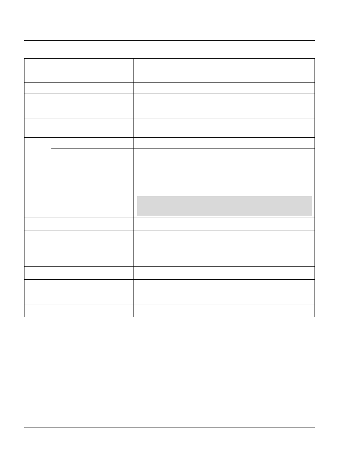
A List of Direct Key Combinations
CTL+ INPUT (1-10) Switches to any selected signal found in the Entry List.
T o enable this combination, you must f irst assign specif ic remote ke ys for direct input
selection in the Entry Edit window.
CTL+ ENTER (While displaying Entry list) Displays the Entry Edit Command window.
CTL+ MUTE PICTURE(SHUTTER) Blocks all Projector Light Output.
CTL+CANCEL Returns to the previous menu without closing the slidebar or dialog.
CTL+ UNDO Clears all menus or adjustment/setting screens. All adjustments are saved automati-
cally.
CTL+ / / ▲ / ▼ Moves the slidebar or dialog box horizontally or vertically.
While using zoom on remote control: Displays the magnifying glass icon.
(BS) Deletes one letter or numeral in the entry screen.
CTL+
CTL+TEST Displays the Passcode Entry window.
INPUT(1-10) in SW Level mode Displays the Select switcher Input Slot window.
NOTE: This feature is available for SW 2 Level mode only.
When the SW 1 Level mode is selected, pressing INPUT key switches to the
corresponding slot without displaying the Select Slot window.
CTL+ MENU (ADDRESS) Displays the remote ID entry window.
CTL+ ADJUST IMAGE (PROJECTOR) Sequentially selects the Projector Options sub menu.
CTL+ POSITION (LENS) Displays the Lens Shift control window.
CTL+ KEYSTONE (R) Turns on red. Available only when the projector is in the test pattern mode.
CTL+ AMPLITUDE (G) Turns on green. Available only when the projector is in the test pattern mode.
CTL+ ENTRY LIST (B) Turns on blue. Available only when the projector is in the test pattern mode.
CTL+ MAGNIFY (ZOOM) Zooms the lens in and out
CTL+ (FOCUS) Adjusts the lens focus.
E – 30
Page 31
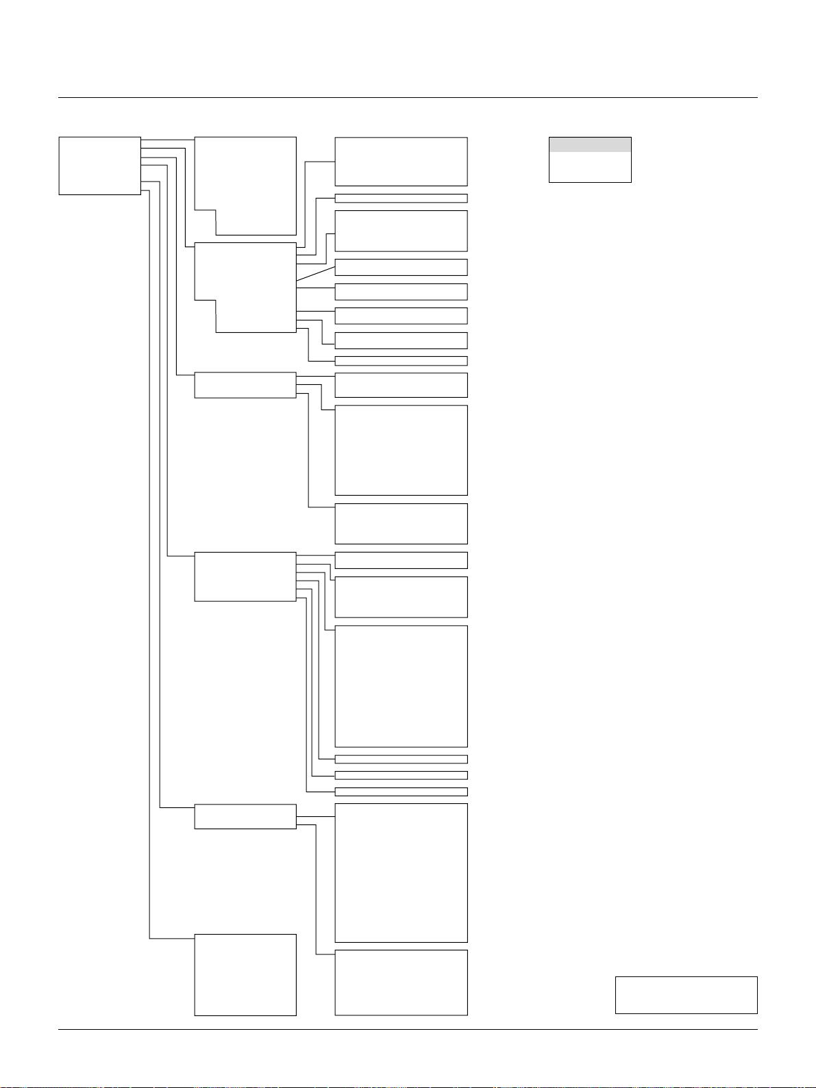
Menu Tree
Menu Sub menu Items
*
Source Select
Adjustments
Image Options
Projector Options
PC Card Files
Help
Test Pattern
RGB 1
RGB 2
RGB 3
Component (YCrCb)
Video 1
Video 2
S-Video 1
S-Video 2
more
RGB (DIGITAL)
SDI
Entry List
Picture
Blanking
Image
Color Temperature
White Balance
Switcher
more
Keystone
Ref. White Bal.
Lamp
Factory Default
Image Mode
Video Mode
Signal Level
Timer
Menu
Setup
Link Mode
Switcher Control
Passcode
Contents
Source Information
Projector Information
Red/ Green/ Blue
Cross Hatch
Gray Scale
Raster (0%)
Raster (25%)
Raster (50%)
Raster (100%)
Focus
Raster Blue
Raster Gray
Brightness
Contrast
Color
Hue
Sharpness
V-Aperture
Top/ Bottom/ Left/ Right
Auto Adjust
Position
Pixel Adjust
Resolution
Video Filter
Brightness R/G/B
Contrast R/G/B
Gain R/G/B
Volume
Brightness R/G/B
Contrast R/G/B
Lamp Mode
Lamp Output
All Data/ Current Signal
Aspect Ratio
VD Delay
Clamp Timing
Gamma
Noise Reduction
Color Matrix
Y/C Delay
Motion Select
Motion Level
YTR Adjustment
CTR Adjustment
Telecine
Auto Control
White
R/G/B Gain
Y/Cb/Cr Gain
Y/Pb/Pr Gain
On/Off Timer
Sleep Timer Off/0:30/1:00/1:30/2:00
Language
Menu Display Time
Date,Time Preset
Display Select
Date Format
Orientation
Background
Signal Select
Power Management
Power Off Confirmation
Keystone Save
User Name
Closed Caption
S-Video Mode Select
Sync Termination
Projector ID
Default Source Select
Communication Port
Communication Speed
Standalone/Master/Slave
Standalone/SW 1 Level/SW 2 Level
Entry/Disable
Source Name
Input Terminal
Entry No.
Horizontal Frequency
Vertical Frequency
Sync Polarity
Signal Type
Video Type
Sync Type
Interlace
Resolution
Direct Key
Aspect Ratio
Gamma
Noise Reduction
Color Matrix
Matrix Type
User Name
Serial Number
Lamp Hour Meter
Filter Usage
Projector Usage
Version
Formatter Version
Link Mode
* When Switcher Control is turned on:
Source Select
Switcher
Entry List
On/Off
Horizontal/Vertical
Clock/Phase
Auto/Native/Native with Zoom
(4 Level)
Variable/Auto/High-Bright
Normal/Zoom/Wide Zoom/Cinema/Anamorphic
0/2. 5u/5u/10u
Auto/Tri-Sync/Front Porch
NTSC,Graphics,Graphics/NTSC,PAL/SECAM2.8,PAL/SECAM,Natural1,Natural2
Luminance OFF/Low/Medium/High
Chrominance OFF/Low/Medium/High
Select Color Matrix HDTV/SDTV
Select Color Matrix Type B-Y/R-Y, U/V, Cb/Cr, Pb/Pr, IVX
(-8 ~ +8)
Still/Adaptive
(-2~+2)
Gain(0~7)
Gain(0~7)
Off/Auto
Execute Auto Control
English/Deutsch/Français/Italiano/Español/Svenska/Japanese
Manual/Auto 3sec/Auto 10sec/Auto 30sec
Date/Time/Input Terminal/Source Name/Projector ID
DD/MM/YY ˇ
Front Floor/Rear Ceiling/Rear Floor/Front Ceiling
Blue/Black/Logo
RGB1/RGB2 Auto/RGB Component
VIDEO1,2/S-VIDEO1,2/Switcher Auto/NTSC3.58/NTSC4.43/PAL/PAL60/SECAM
On/Off
On/Off
On/Off
Off/Caption1-4/Text1-4
Off/S1/S2
RGB1/RGB2 75Ω/Hi-Z
Enable/Disable 1-64
Last/Select
D-SUB/IR
4800/9600/19200/38400
Separate Sync/G-Sync/Tri-Sync/Mix Sync
Interlace/Non-Interlace
BIOS/Firmware/Data/SUB-CPU
CPU/PROM/Prism
NOTE: Items indicated in
white are not available.
E – 31
Page 32

Menu Elements
Title bar
Highlight
Solid triangle
Tab
Cancel Button
OK Button
Check box
Radio button
Slide bar
Menu windows or dialog box typically have the following elements:
Title bar: Indicates the menu title.
Highlight: Indicates the selected menu or item.
Solid triangle: Indicates further choices are available. A highlighted triangle indicates the item is active.
Tab: Indicates a group of features in a dialog box. Selecting any tab brings its page to the front.
Radio button: Use this round button to select an option in a dialog box.
Check box: Place a checkmark in the square box to turn the option On.
Slide bar: Indicates settings or the direction of adjustment.
OK button: Press to confirm your setting. You will return to the previous menu.
Cancel button: Press to cancel your setting. You will return to the previous menu.
E – 32
Page 33

Menu Descriptions & Functions
Source Select
Enables you to select a video source such as a VCR, DVD player,
laser disc player, computer or document camera depending on what is
connected to your inputs.
Press the up/down buttons on your remote control or the projector
cabinet to highlight the menu for the item you want to adjust.
* RGB1,2,3
* Component (YCbCr)
* Video 1, 2
* S-Video 1, 2
* RGB Digital
* SDI
* Entry List—Displays the list of the entry signals. Use the ▲/▼ but-
tons on your remote control or the projector cabinet to select the
signal and press the ENTER button on the remote control or the
projector cabinet to project the image of the selected source.
* Edit Enables you to change source name or assign the direct key.
* The following buttons are not available for the currently projecting
signals:
1) The Cut and Paste buttons on the Entry Edit Command screen
2) The Input Terminal button on the Entry Edit screen
When complete, select OK and press ENTER. T o e xit without storing
setting, select Cancel.
Select “Source Name” and press ENTER to display the Source Name
Edit window. You can change source name on this window.
Select "Input T erminal" and press ENTER to display the Input Terminal window. You can change input terminal on this window.
Select “Direct Key” and press ENTER to display the Direct Key window . Y ou can assign specific remote ke ys for direct signal input selection.
NOTE: Existing direct key settings are overwritten with new settings.
Entry Edit Command (Expert mode only)
You can edit the signal on the entry list.
To do so:
1)While pressing and holding CTL, press ENTER on the remote control to display the Entry Edit Command window.
* Cut Enables you to remove a selected signal from the list and place
it on the “clipboard” in the projector.
* Copy Enables you to copy a selected signal from the list and place
it on the “clipboard” in the projector.
* Paste Enables you to paste the signal placed on the “clip-board”
to any other line of the list. T o do this, select “Paste” and then select
the line number you want to paste to. Last press ENTER.
Select “List” and press ENTER to display the direct Key assignment
list.
Select “OK” and press ENTER to close the window.
To close the List window, press CANCEL on the remote.
E – 33
Page 34

Adjustments
The Adjustments Menu provides access to controls for your image.
Use the ▲/▼ buttons on your remote control or the projector cabinet
to highlight the menu for the item you want to adjust.
Picture
Image
Auto Adjust:
When “Auto Adjust” is set to “On”, the projector automatically
determines the best resolution for the current RGB input signal to
project an image using NEC’s Advanced AccuBlend Intelligent
Pixel Blending Technology. The image can be automatically adjusted for geometry and stability; “Horizontal Position”, “Vertical
Position” and “Pixel Adjust. ”
On: Automatically adjusts image “Horizontal Position”, “Ver-
tical Position” and “Pixel Adjust. ”
Off: User can adjust the image display functions (“Horizon-
tal Position”, “Vertical Position” and “Pixel Adjust”)
manually.
Horizontal/Vertical Position (when Auto Adjust is off):
Adjusts the image location from left to right.
This adjustment is made automatically when the Auto Adjust is
turned on.
Brightness: Adjusts the brightness level or the back raster inten-
sity.
Contrast: Adjusts the intensity of the image according to the
incoming signal.
Color: Increases or decreases the color saturation level (not
available for RGB).
Hue: Varies the color level from +/- green to +/-blue. The
red level is used as reference. This adjustment is only
valid for Video and Component inputs (Not available
RGB).
Sharpness: Controls the detail of the image for Video (Not avail-
able for RGB and Component).
V-Aperture: Adjusts edge enhancement in the vertical direction.
(Not available for RGB)
Blanking
This feature allows you to mask any unwanted area of the screen image.
Pixel Adjust (when Auto Adjust is off):
Displays the Clock and Phase adjustments.
Clock: Use this item with the “Auto Adjust off” to fine tune the
computer image or to remove any vertical banding that
might appear.
Phase: Use this item to adjust the clock phase or to reduce video
noise, dot interference or cross talk. (This is evident when
part of your image appears to be shimmering.) Use the
and buttons to adjust the image.
Use “Phase” only after the “Clock” is complete.
Resolution (when Auto Adjust is off):
This allows you to activ ate or deactivate the Adv anced AccuBlend
feature.
Auto: Turns on the Advanced AccuBlend feature. The projec-
tor automatically reduces or enlarges the current image
to fit the full screen.
Native: Turns off the Advanced AccuBlend feature. The projec-
tor displays the current image in its true resolution.
NOTE: While you are displaying an image with higher resolution
than the projector’s native resolution, even when you are in the
Native mode, the image is displayed full screen using the Advanced
AccuBlend feature.
Native with Zoom: Enlarges the image to fill the screen in the
Native mode.
NOTE: Unless the projector is used at 0 degree of lens vertical
offset, you cannot get a correct display position.
E – 34
Page 35

Video Filter
This feature reduces video noise. Select the appropriate filter for
your signal.
Bar 0 ..................... Off
Bar 1/3 .................. High
Bar 2/3 .................. Medium
Bar full ................. Low
Color Temperature
This feature adjusts the color temperature using the slide bar.
White Balance (Expert mode only)
Keystone
Keystone is the distortion of a projected image that usually creates a wider top than bottom. Aiming a projector upward on a w all
rather than straight at a wall creates this distortion. Use the or
buttons on the slide bar to correct this keystone (trapezoidal)
distortion.
NOTE: With the projector aimed directly at the screen the maximum keystone angle that can be corrected is +/- 15 degrees.
Reference White Balance (Expert mode only)
This feature adjusts the white balance that is used as a reference.
This adjustment affects all sources. The Ref.White Bal. is available for test pattern only.
Lamp (Expert mode only)
Lamp Mode
This feature adjusts the white balance for each signal.
For Video/RGB ..... Brightness for each color (RGB) is used to
adjust the black level of the screen; Contrast
for each color (RGB) to adjust the white level
of the screen.
For Y/Cb/Cr ..........Brightness for each color (Y/Cb/Cr) is used
to adjust the white level of the screen; Contrast for each color (Y/Cb/Cr) is used to adjust the black level of the screen.
Switcher (available only when used with ISS-6020)
Gain
This feature adjusts the input level of the signal. This must be
done to each color:R, G, and B.
Volume
This feature adjusts the volume of the audio output. Adjust the sound
corresponding to the slot.
This feature allows the lamp power supply to operate under three
settings.
Auto: This setting keeps the projector's original light output
level for a certain period of time.
High-Bright: This setting consumes maximum current from the
AC input and results in the most light output.
NOTE: The High Bright mode shortens the lamp life. Be sure to
use this mode at temperature of 95˚ F (35˚C) or less.
V ariable:This setting allows the lamp power supply to draw a vari-
able amount of current from the AC input source and
allows for maximum power consumption and variable
light output.
Lamp Output
When selecting “Variable”, use the slidebar to adjust for desired
projector light output.
E – 35
Page 36

Factory Default
VD Delay (Expert mode only):
This feature is used to correct vertical jitter of non-standard interlaced signal. Select one of the three VD delay levels.
Returns all adjustments and settings to the factory preset level.
All Data: Resets all adjustments and settings for all the
signals to the factory preset.
Including Entry List
Current Signal: Resets the adjustments for the current signal
NOTE: The items that can be reset are all the items in the Adjustments and Image Options except for Keystone and Lamp Output.
: Also deletes all the signals in the Entry List
and returns to the factory preset.
to the factory preset levels.
Image Options
Provides optional controls such as gamma correction, component
signal selection, wide screen and video noise reduction features.
Image Mode
Clamp Timing (Expert mode only):
This function sets the standard black level position of the displayed
image. Select one of the following three options.
Auto: Normal setting.
Tri-Sync: Setting for HDTV signal
Front Porch: For other settings than above
Video Mode
Aspect Ratio: This feature allows you to display the incoming
video signal in the correct proportion.
Normal: Displays normal video picture with a 4-to-3 aspect ratio
as is.
Zoom: Displays DVD’s video picture with a 16-to-9 aspect ra-
tio expanded in the horizontal and vertical direction,
maintaining the original proportion.
Wide Zoom: Displays DVD’s squeezed video picture with a
16-to-9 aspect ratio expanded in the horizontal direction, converted to 4-to-3 aspect ratio.
Cinema: Displays DVD’s squeeze video picture with a 16-to-9
aspect ratio compressed in the vertical direction, maintaining the 16-to-9 aspect ratio.
Anamorphic: Select this mode for use of anamorphic lens. This
mode will change the aspect ratio according to the lens.
Gamma
This option corrects gamma. Select the appropriate item.
NTSC : Setting for NTSC signals
Graphics : Setting for Computer Graphics
Graphics/NTSC : Setting for both Computer Graphics and
NTSC signals
PAL/SECAM 2.8 : Setting for PAL and SECAM signals at the
gamma value of 2.8
PAL/SECAM : Setting for PAL and SECAM signals
Natural 1 : Setting for Video and S-Video signal
Natural 2 : Setting for component signal
E – 36
Page 37

Noise Reduction
Select one of the following three levels for reducing video noise.
Low, Medium or High.
NOTE: The lower the Noise Reduction level, the better the image
quality. Increasing Noise Reduction lowers video bandwidth.
Color Matrix
First, select an appropriate color matrix for your input signal, either
HDTV or SDTV. Then select an appropriate matrix type from B-Y/RY, Cb/Cr, Pb/Pr or IVX.
NOTE: The Color Matrix feature is a vailable for component video
signal only.
Y/C Delay: Adjusts Y/C delay level.
Motion Select: Sets the interpolation method. Selects Still or
Adaptive. Still is used for non moving images such
as a document camera. Select Adapter for all motion video.
Motion Level: Adjusts level of motion detection when Adaptive
is selected.
YTR Adjustmen (Expert mode only):
Adjusts Luminance Transient Time.
CTR Adjustment (Expert mode only):
Adjusts Chroma Transient Time.
Telecine(Expert mode only)
Use 3:2 pull down correction to eliminate jitter and artifacts in video.
Auto: For film source such as a DVD player
Off: For signals other than film sources
Signal Level
This function is only active when multiple projectors are in use.
Auto Control: Select OK to execute Auto Control.
White: Adjust saturation at the white peak.
R/G/B, Y/Cb/Cr or Y/Pb/Pr Gain (for Expert mode only):
Adjust RGB, Component or HDTV Gain to match
multiple projector color uniformity.
Projector Options
Enables you to set preferences and other operating options.
Timer
Enables you to turn on or off your projector automatically at a
specified time. Two timer functions are available: On/Off Timer
and Sleep Timer.
E – 37
Page 38

On/Off Timer
Up to eight settings can be programmed.
• Before setting On/Off Timer, make sure that Date, Time Preset feature is set.
• Even after setting On/Off Timer, turning the projector on or
off with the remote control is possible.
• There are two time display formats: 24-hour or AM/PM format.
1. Select your desired time between 30 minutes and 2 hours in 30
minutes.
2. Select Set and press the ENTER button on the remote control.
3. The remaining time starts counting down.
4. The projector will turn off after the countdown is complete.
Menu
Allows you to set preferences for the on-screen menu.
1. Open the On/OFF Timer window.
2. Select EDIT and press ENTER on the remote control to open the
EDIT window.
3. Set the Week, Day, On-Time and Off-Time using the CURSOR
buttons and INPUT buttons (1 thru 10). To cancel the on-time or
off time, use Delete.
4. Select Set and press the ENTER button on the remote control to
complete the setting. To close, select Close.
5. To enable your setting, select Active on the Execute Switch.
6. Select OK and press the ENTER button on the remote control to
complete the setting.
NOTE: When On Timer is set and the projector is in the standby
mode, the "00" display on the INDICATOR flashes to show that
On Timer program is active.
The projector must be in stand-by mode at the time of turning on.
The preset power-on time will be v oid if the cooling fan is working or
an error occurs.
Language:
Y ou can choose one of se ven languages for on-screen instructions.
The options are: English, German, French, Italian, Spanish, Swedish and Japanese.
Menu Display Time:
Auto: The on-screen menu display appears when the buttons
on the remote control, or the controls on the rear panel
are pressed. The on-screen display will turn off at a
preselected time. The turn-off time is specified in seconds up to a maximum of 30 seconds. Select your desired time (3-30 seconds) from the menu.
Manual: The on-screen menu display appears when the buttons
on the remote control, or the controls on the rear panel
are pressed. The display will be turned on and off whenever the MUTE OSD button is pressed. If no button operation is made for 20 minutes or more, the on-screen
message will automatically turn off.
Date Format:
Eight display formats can be selected. This date format sets the
current date that appears on the upper left corner of the screen.
Date, Time Preset:
Setting the Current Date and Time
Sleep Timer
You can set the current time, month, date, and year.
E – 38
Page 39

1. Type in date.
Enter month, date and year in this order using INPUT buttons on
the remote control.
Month and date must be entered in two digits. For example, to
display "February", press "0" and "2".
2. Type in time.
Time is expressed in the 24-hour format. For example, 6:00 p.m.
is entered as 18:00.
3. Select "OK" and press ENTER.
Closing the window allows the clock to start.
The current year, month, date and time are displayed on the top of
the screen.
NOTE: The projector has a b uilt-in clock. The clock will keep working for about 3 days after the main power is turned off.
If the main power is off for 3 days or more, the built-in clock will
be reset. If the built-in clock is reset, set the date and time again.
The built-in clock will not reset while in the standby condition.
Display Select:
You can choose the desired status information to be displayed on
the screen. The desired status information will be displayed each
time you switch between sources.
Setup
Enables you to set operating options.
Select “OK” to sa ve your changes for all the features of Page1, Page2,
Page3 and Page 4.
<Page 1>
S-Video Mode Select:
This feature is used to select the S-Video signal detection mode.
This allows identifying of the S-Video signals with different aspect ratio (Zoom signal 16:9, Wide Zoom signal 4:3).
S1: Identifies a Zoom signal only.
S2: Identifies Zoom or Wide Zoom signal.
OFF: Does not identify any S-video signal.
<Page 2>
Signal Select:
RGB 1/2: Allows you to choose “RGB” for an RGB source such
as a computer, or “Component” for a component video
source such as a DVD player . Normally select “Auto”
and the projector automatically detects a component
signal. However there may be some component signals that the projector is unable to detect. If this is the
case, select “Component”.
<Video 1/2 and S-Video System 1/2, Switcher>
This feature enables you to select composite video standards manually. Normally select “Auto”.
This must be done for Video, S-Video and switcher respectively.
“Switcher” is setting for V ideo and S-V ideo in SW 1 Lev el or 2 mode.
Orientation:
This orients the screen image to match the physical orientation of
the projector.
The options are:front floor projection, rear ceiling projection, rear
floor projection, and front ceiling projection.
Background:
Use this feature to display a black, blue screen or logo when no
signal is available.
Closed Caption:
This feature displays a list of nine selectable text and captioning
options. Select the best option to match the captioning format you
are using.
The closed caption feature works with NTSC3.58 source only.
<Page 3>
Power Management:
When this option is on and there is no RGB input for five minutes
or more, the projector will automatically turn itself off. Power
Management is not active for Video signals.
Power Off Confirmation:
This option determines whether a confirmation dialog for turning
off the projector will appear or not.
Keystone Save:
This option enables you to save your current keystone settings.
Keystone Save affects all sources globally. The changes are saved
when you turn off the projector.
E – 39
Page 40

User Name:
Type in your desired name using the INPUT keys on the remote
control.
Select one character at a time with the INPUT buttons 1 through
10(0) and by moving the cursor with the CURSOR button. The
user name must be 18 characters or less.
Only after completely finishing the selection of the characters,
press ENTER.
Sync Termination (RGB1/2):
This functions is used to select the impedance of the sync signal.
Select “ 75 Ω” or “Hi-Z”.
NOTE: The default setting is “75 Ω”. This should be “75 Ω” for
normal use. Select the “Hi-Z” when inputting a TTL signal.
Projector ID:
Each projector needs its own unique addresses when used in serial communication mode. You can choose one of 64 unique address using the spin box. First select Enable. Keep pressing
increases the number.
To make your setting available, select OK.
<Page 4 Expert mode only>
Switcher Control (Expert mode only):
This feature sets the projector in communication with the NEC
ISS-6020 Switchers.
Stand Alone: Use the projector in stand alone operation.
SW 1 Level: Use the projector with one Switcher.
SW 2 Level: Use the projector with two or more Switchers.
When changing this setting, the confirmation message will appear.
If you want to restart your projector, select Yes; if not, select No.
NOTE: This setting becomes effective only after the projector is
restarted.
Passcode (Expert mode only):
T o prevent an y unauthorized operation or mis-adjustment, the projector is equipped with a passcode option. If your passcode has
not been entered correctly, the Expert item will not be available.
Press and hold CTL, then press TEST on the remote control to
display Passcode window.
Entry: Registers new passcode.
Communication/Port:
Not used.
Speed:
This feature sets baud rate of the OPTION IN (D-Sub 9 pin) connector from 4800 to 38400 bps.
The default is 38400 bps. Select the appropriate baud rate for your
equipment to be connected.
Default Source Select: Last/Select:
You can set the projector to default to any one of its inputs each
time the projector is turned on.
Last: Sets the projector to default to the previous or last active
input each time the projector is turned on.
Select: Displays the selected source input every time the pro-
jector is started up.
Link Mode (Expert mode only):
This feature is used for multiple projector connection using RGB
Digital Input/Output connectors.
The master projector is set to Master.
The other slave projectors are set to Slave.
When not using Link mode, set to Standalone.
See page E-20 for setting up for double or stacking in link mode.
To register a new passcode:
1) Select Entry to open the Entry window.
2) Enter a four digit passcode using the “1” through “10” buttons. Each time you press the INPUT button, an asterisk will
appear next to the “Enter the Passcode” message.
NOTE: “0000” and “9999” cannot be used as a passcode.
3) Once you have finished entering your FOUR DIGIT passcode,
press ENTER to store the passcode. You will return to the
passcode menu.
NOTE:
1. If you have made an error, press CTL + to delete the
asterisk “*”. Then re-enter the correct passcode.
2. If the passcode has been entered correctly, the “Confirm
Passcode...” window will be displayed.
3. If the passcode is not entered correctly, the “Warning
Passcode!!” message will be displayed. You will be required
to enter the passcode correctly. While pressing and holding
CTL, then pressing TEST displays the Passcode Entry window. Type in your registered passcode.
Delete: Deletes the registered passcode.
Select OK in the Delete Passcode window.
E – 40
Page 41

PC Card Files
Displays a list of all the files stored in the PC card so that you can
select a file you want to display . Y ou can also sort f iles by file name or
date, or display the file.
Although a list of all the files in the PC card is displayed, you can
view files in text, HTML, JPEG and BMP format only.
Selecting “Execute” displays the file you selected.
Help
Contents
Provides online help menus. An undelined link means that you can
move to an adjustment item directly.
Selecting the underlined link and pressing ENTER moves to the corresponding adjustment item.
Source Information
Displaying Current Status of Link Mode
When selecting the tab "Page 4 ", you will get the following dialog
box.
Master ID : Indicates the Master projector
Status : Indicates the status of the master projector
Connected PJ : Indicates number of connected slave pro-
jectors
Slave No. : Indicates serial number of the slave projec-
tor
ID : Indicates ID of a slave projector
Status : Indicates the status of the slave projector
Page buttons : Turns pages. One screen displays informa-
tion of 3 projectors only. Information of a
maximum of 16 projectors can be displayed
using these page buttons.
Reconnect button : Confirms connection of all linked projec-
tors
Status items
Running : The projector is now working
Cooling Lamp : The fan is now cooling the lamp
Standby : The projector is in stand-by
Communication Error : A communication error has occurred
Connecting... : The projector is now verifying for connec-
tion
Error Standby : An error caused the projector to enter the
stand-by mode
Displays the status of the current signal. This dialog box has three
pages.
Projector Information
Displays the information for your projector such as lamp usage, serial
number and version number etc..
Test Pattern
Nine test patterns can be selected. You can turn on or off red, green, or
blue respectively.
E – 41
Page 42

5. Specifications
Optical
1
Panel *
Lamp 1.0kW Bubble Type Short Arc Xenon
Light Output 4500 ANSI Lumens (High Bright mode)
Brightness Uniformity >80% edge to center
Contrast Ratio 400 : 1 Full On/Off
Lens Movement Motorized Horizontal and Vertical Lens Shift
DMDTM .9" x 3
1024 x 768 native resolution up to 1280 x 1024 with advanced AccuBlend
Built in:Overheat Protection
Lamp Over-Usage Protection
4000 ANSI Lumens (Normal mode)
Full Light Output at 200- 240V
250 : 1 ANSI
Built in Lens Shutter
TM
T echnology
Lens Options*
Image Size 80 - 500" diagonal at 4:3
2
TL-08SF 0.84 (Short focal lens)
TL-1Z 1.5 - 2.5 : 1 (Zoom lens)
TL-2Z 2.5 - 4.0 : 1 (Zoom lens)
TL-4Z 4.0 - 7.0 : 1 (Zoom lens)
Electrical
Scan Rate Horizontal: 15 - 83.5 kHz
Vertical: 50 - 85 Hz
Pixel Clock 100MHz
Inputs RGB / YCr/Pr,Cb/Pb (2) BNC
RGB H (HV) V (1) D-dub 15 pin
YPbPr / YCrCb (1) RCA
Video (1) BNC (1) RCA
S-Video (1) S-Video Terminal
Y/C (1) BNC
Digital I/O
RGB DIGITAL (1) MDR 20pin
DFP Specification ( Max resolutions : XGA )
(1) Process Out MDR 20 pin
SDI(Option) (1) BNC
SMPTE 259M Level C, 4:2:2 525/625 Component
(1) BNC Through out
PC Card (1) PCMCIA Data Back-up
Input Compatibility NTSC, PAL, SECAM, HDTV (1080I, 720p, 480p), VGA, SVGA, XGA, SXGA, MAC
Video 3D Y/C Separation
Telecine Detect: 3:2 pull down correction
E – 42
Page 43

Acceptable Sync Sys Separate Sync/Composite Sync/ Sync on Green
Memory 100 individual memory locations
Menu System Pull down multilingual on-screen display
English/German/French/Italian/Spanish/
Swedish/Japanese
Keystone Correction Digital through Advanced AccuBlend Technology
Range 0 - ±30˚
External Control RS232C (1) D-sub 9 pin
Contact Closure
Switcher (2) D-sub 15 pin In/Out
Addressable Remote Control (wired / wireless)
Power Requirement 100-120 / 200-240 VAC, 50/60Hz
Input Current 11 / 7.3 A
Power Consumption 1.0 / 1.5 kW
Mechanical
Installation Orientation: Floor/Front, Floor/Rear, Ceiling/Front, Ceiling/Rear
Stacking: Up to 3 projectors can be gravity stacked
Dimensions 22.0" (W) x 26.9" (D) x 12.2" (H) with foot (not including lens)
560 mm (W) x 682 mm (D) x 308 mm (H) with foot (not including lens)
Net Weight 94.8 lbs (43Kg)
Environment Operational Temperature 40˚ to 95˚F / 5˚ to 35˚C,
Humidity: 20-80% non-condensing
Storage: 14˚ to 122˚F / -10˚ to 50˚C
Regulations USA UL 1950 FCC Class A
Canada CSA950 ( C-UL )
Europe EN60950 EN55022 Class A EN55024 EN61000-3-2 EN61000-3-3
Japan MITI VCCI I
EN60950 2
Oceania EN60950 AS/NZS3548 Class A
Asia EN60850 CISPR22
*1: Permissible deviation for RGB convergence (Pixel deviation) is 1/2 pixel or less at center; 1 pixel or less
around the perimeter (when projection upward angle is 0˚).
*2: When using the zoom lens, it is recommended that the projector is positioned at an angle of from -15 to +15
degrees from the horizontal.
Specifications are subject to change without notice.
nd
edition
E – 43
Page 44

6. Optional Accessories
Link Mode: Compatible Input Signal List
7.
(Expert mode only)
Lens TL-08SF (Short Focal Lens 0.84)
TL-1Z (Zoom Lens 1.5 - 2.5:1)
TL-2Z (Zoom Lens 2.5 - 4.0:1)
TL-4Z (Zoom Lens 4.0 - 7.0:1)
Cable XT D-CABLE 5M (DFP cable)
Interface Board XT SDI BOARD
Ceiling Mount Kit XT CMKIT
Switcher ISS-6020 Video/RGB Switcher
NOTE: Signals other than specified here are not available in the
digital link mode.
If you want to input them, use a commercially available distribution amplifier to connect the terminals of each projector.
Signal Type Standard Resolution
Analog Signal
Digital Signal
Analog RGB
Video Signal
Digital RGB
Digital Serial
VESA XGA@70Hz
VESA XGA@75Hz
VESA VGA@72Hz
VESA VGA@75Hz
VESA VGA@85Hz
VESA SVGA@56Hz
VESA SVGA@60Hz
VESA SVGA@85Hz
VESA XGA@60Hz
VESA XGA@70Hz
VESA XGA@75Hz
APPLE MAC13"@67Hz
APPLE MAC16"@75Hz
IBM VGA-400@70Hz
IBM XGA2-768@72Hz
3.58NTSC
BW@60
PAL
SECAM
BW@50
VESA VGA@60Hz
VESA SVGA@60Hz
VESA XGA@60Hz
SDI 525
SDI 625
1024 x 768
1024 x 768
640 x 480
640 x 480
640 x 480
800 x 600
800 x 600
800 x 600
1024 x 768
1024 x 768
1024 x 768
640 x 480
832 x 624
720 x 400
1024 x 768
–
–
–
–
–
640 x 480
800 x 600
1024 x 768
–
–
Sync Frequency
H(kHz) V(Hz)
56.5kHz
60.0kHz
37.9kHz
37.5kHz
43.3kHz
35.1kHz
37.9kHz
53.7kHz
48.4kHz
56.5kHz
60.0kHz
35.0kHz
49.7kHz
31.5kHz
58.1kHz
–
–
–
–
–
31.5kHz
37.9kHz
48.4kHz
–
–
70Hz
75Hz
72Hz
75Hz
85Hz
56Hz
60Hz
85Hz
60Hz
70Hz
75Hz
67Hz
75Hz
70Hz
72Hz
–
–
–
–
–
60Hz
60Hz
60Hz
–
–
Pixel
(MHz)
75.0MHz
78.8MHz
31.5MHz
31.5MHz
36.0MHz
36.0MHz
40.0MHz
56.3MHz
65.0MHz
75.0MHz
78.8MHz
30.2MHz
57.3MHz
28.3MHz
79.0MHz
–
–
–
–
–
31.5MHz
40.0MHz
65.0MHz
–
–
Note
*1
*1
*1, 2
*1, 2
*1, 2
*1, 2
*1, 2
*1
*1
*1
*1
*1, 2
*1
*1, 2
*1
*1 In Link Mode the Pixel Clock adjustment range of the slave pro-
jector is narrow. You can only adjust the pixel clock within this
range.
*2 Please adjust Pixel Phase so that the slave projector is in phase
with the master projector.
Note that Link mode and Switcher Control mode are not available at
the same time.
E – 44
Page 45

List of Menu Items Available on Link Mode (Expert Mode)
8.
See the table below for available functions in the digital link mode
and the analog link mode.
Menu (Expert mode)
Source Select L L
Adjustments Picture (all items) L L
Blanking L L
Image Auto Adjust N M
Position L L
Pixel Adjust L M
Resolution L L
Video Filter L L
Color Temperature L L
White Balance L L
Switcher N N
Keystone L L
Ref. White Balance N N
Lamp N N
Factory Default N N
Image Options Image Mode Aspect Ratio L L
VD Delay N N
Clamp Timing N N
Video Mode Gamma L L
Noise Reduction L N
Color Matrix L N
Y/C Delay L N
Motion Select L N
Motion Level L N
YTR Adjustment L N
CTR Adjustment L N
Telecine L N
Signal Level White L L
RGB Gain L L
Y/Cb/Cr Gain L L
Y/Pb/Pr Gain L L
Projector Timer L L
Options Menu M M
Setup N N
Link Mode M M
Switcher Control N N
Passcode M M
PC Card Files N N
Help M M
Test Pattern N N
Direct Key LENS SHIFT I I
FOCUS I I
ZOOM I I
MENU L L
POWER I I
INPUT M L
MUTE (PICTURE/SHUTTER/OSD) L L
Digital Link Analog Link
Each letter used in the above note means the following
Letter Master projector Slave projector (s)
L valid linked
N invalid invalid
M valid invalid
I independently adjustable independently adjustable
E – 45
Page 46
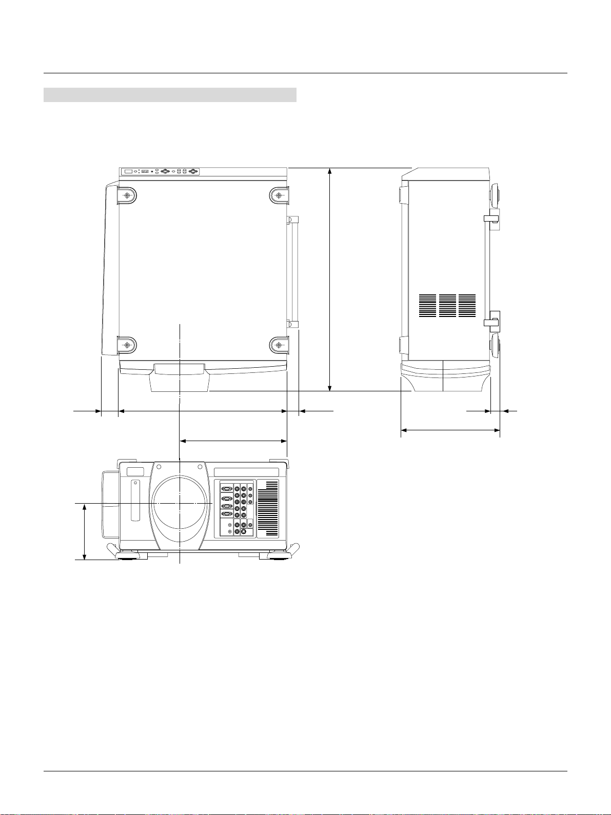
Appendix
Dimensions
682 (26.85)
54
(2.13)
174 (6.85)
506 (19.92)
326 (12.83)
35.5 (1.40)
308 (12.13)
The drawings do not include the lens part.
Unit: mm (inch)
30 (1.18)
E – 46
 Loading...