

Quick Set-up Guide
Diagonal Width(W ) Height(H)
inches inches inches inches inches inches
40 32 24 26.0 2.5 14.0
60 48 36 37.0 10.3 19.0
67 53.6 40.2 40.8 13.1 20.7
72 57.6 43.2 43.6 15.0 22.0
84 67.2 50.4 50.2 19.7 25.0
90 72 54 53.5 22.0 26.5
100 80 60 59. 0 25.9 29.0
Image Size (4:3)
BCD
(4:3)
Diagonal Width(W ) Height(H)
inches inches inches inches inches inches
37 32 18 26.0 2. 5 17.0
40 35 19.7 28.0 4. 0 18.2
83 72 40.5 53.5 22.0 33.2
92 80 45 59.0 25.9 36.5
D
(16:9)
Image Size (16:9)
BC
WT610E short throw projector
STEP-BY-STEP PROJECTOR PLACEMENT FOR FRONT SCREEN TABLE TOP USE
1. PROJECTOR PLACEMENT
Place projector on table in front of screen or
wall which will be used for displaying image.
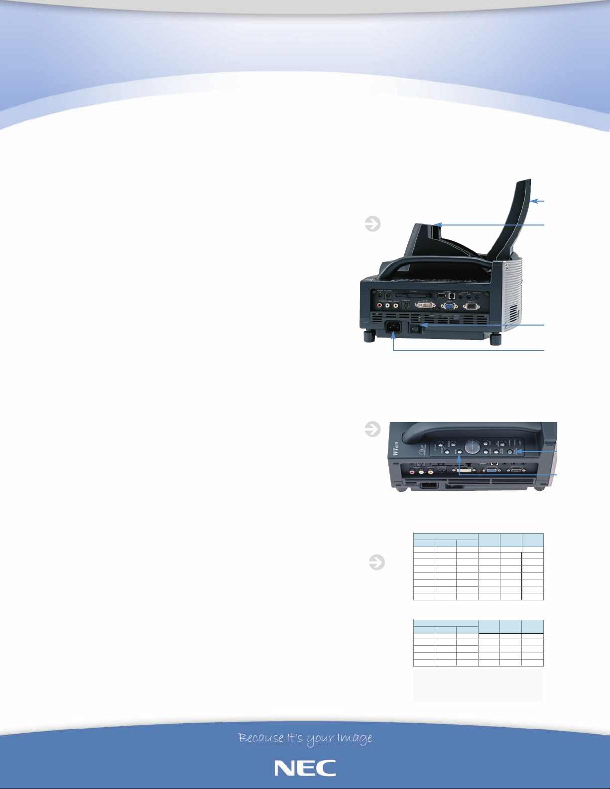
2. OPENING THE MIRROR
Unlock mirror cover lock switch and open
top mirror door to the open position (figure 1).
3. CONNECTING THE POWER
Plug power cord into projector and AC outlet.
(See Figure 1 for AC Power connection.)
FIGURE 1
TOP MIRROR
DOOR
C
OVER
LOCK
SWITCH
PROJECTOR
POWER SWITCH
AC POWER
INLET
4. TURNING ON THE WT610E
Turn on the main power to the projector; press the PROJECTOR POWER
SWITCH (figure 1) to the on position. Press the POWER (ON/STAND BY)
button on the projector cabinet (figure 2) or POWER ON button on the
remote control (figure 5) for a minimum of 2 seconds, when the POWER
INDICATOR turns a steady green the projector is ready to use.
JECTOR PLACEMENT FOR PROPER SCREEN SIZE
O
PR
.
5
Move projector closer or farther away from screen to fit the width of the
een or desir
scr
ed size. Maximum screen size is 100” diagonal.
NOTEas the
size of the image increases or decreases the displayed vertical image position shifts
depending on screen size (figure 3). Smaller images will have less vertical image
t than larger screen sizes.; you will need to adjust screen height to
shif
accommodate this shift. The distance between the projector and display surface
cannot be changed without changing image size.
CONTINUED ON REVERSE SIDE...
FIGURE 2
FIGURE 3
B Vertical distance between the bottom of the projector and the screen center
w distance
o
Thr
C
er
V
D
(screen top for ceiling mounted application)
een the bottom of the projector and screen bottom
tical distance betw
POWER
BUTTON
"MENU
BUTTON
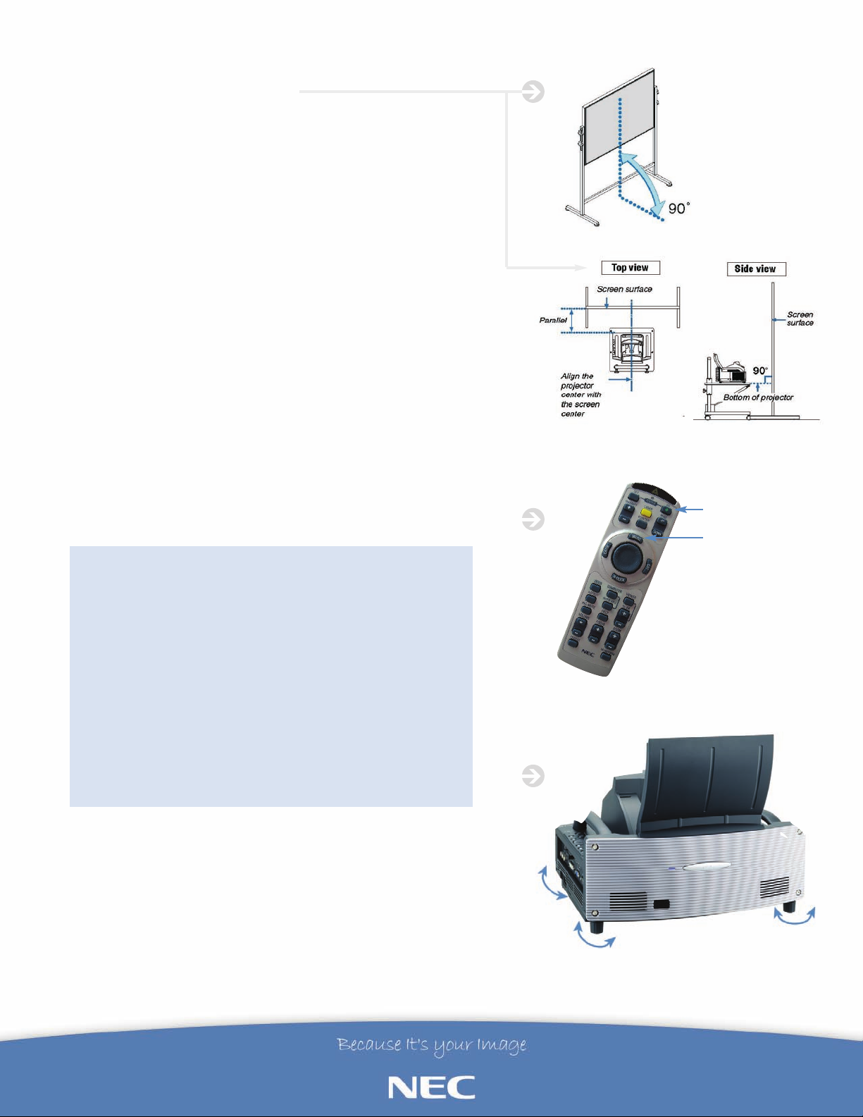
6. SQUARING THE PROJECTOR
TO THE PROJECTOR SURFACE
Projector needs to be in the horizontal center of the screen and
parallel to the screen, this is a very important step to a square image
figure 4).
(
7. REMOTE CONTROL NAVIGATION
Next using the remote or top control panel select “MENU” (figure 2
& 5). From the on-screen menu select “SET-UP” then “TILT
INDICATOR”.
8. MAKING SURE THE WT610E IS
LEVEL WITH THE SURFACE IT IS ON
ilt Indicator to see if projector is level. If projector needs to be
Check T
leveled use the four projector feet (figure 6) to adjust until both tilt
indicator's slider are centered. Tilting the projector will move the Tilt
Indicator’s slider to the left or right accordingly. Tilt the projector so
that both of the sliders of “Back/Front” and “Left/Right” are shown at
the center. When the slider reaches the center, it will become green.
This means the projector is level with the surface it is on.
IGURE 4
F
FIGURE 5
POWER ON
9. ADJUSTING PROJECTOR KEYSTONE AND FOCUS
Since both affect one another it may be necessary to repeat focus
and keystone adjustments until image is square and focused.
a. Bring up test pattern “MENU” • “SOURCE” •“TEST PATTERN”
b. Adjust focus using the keys on remote control or projector
cabinet until test pattern is clear
c. Adjust keystone “MENU” • “SOURCE” • “KEYSTONE” until
image is square
d. Repeat steps b and c until image is acceptable
e. If focus is acceptable but image is not square go back to step
el
v
PRESENT
.
10
6 and check pr
ojector le
You are now ready to begin projecting an image. Plug in VGA
cable to projector and laptop, select input source and PRESENT!
For more information, call 1.800.NEC.INFO or visit www.necvisualsystems.com
NEC is a registered trademark of NEC Corporation. All other trademarks are the property of their
respective owners. All specifications subject to change without notice.
asca, IL 60
ation of America
1248
-
143
NEC Corpor
Visual Systems Division
1250 Arlington Heights Rd., Suite 400
It
MENU
FIGURE 6
UP
DOWN
NEC 090613
 Loading...