

Nec VERSA 5060X, VERSA 5060 SERVICE MANUAL

PROPRIETARY NOTICE AND LIABILITY DISCLAIMER
The information disclosed in this document, including all designs and related materials, is
the valuable property of NEC Computer Systems Division, Packard Bell NEC, Inc.
(NECCSD, P BNEC) and/or its licenso rs. NECCSD and/o r its licensors, as appropriate, reserve all patent, copyright and other proprietary rights to this document, including all design, manufacturing, repro duction, use, and sales r ights thereto, except to the extent said
rights are expressly granted to others.
The NECCSD product(s) discussed in this document are warranted in accordance w ith the
terms of the Warranty Statement accompanying each product. However, actual
performance of each such product is dependent upon factors such as system configuration,
customer data, and oper ator control. Since implementation by customers o f each pro duct
may vary, the suitability of specific product configurations and applications must be
determined by the customer and is not warrant ed by NECCSD.
To allow for design and specification improve ments, the information in this document is
subject to change at any time, without notice. Reproduction of this document or portions
thereof without prior written approval of NECCSD is prohibited.
NEC is a registered trademark, Versa is a U.S. registered trademark, MiniDock, VersaBay, VersaGlide, and
PortBar are trademarks, and UltraCare is a U.S. registered service mark of NEC Corporation, used under
license.
FaxFlash is a service mark of NEC Comput er Systems Divisi on (NECCSD), Packard Bell NEC, Inc.
All oth er product, brand, or trade names used in this publication are the property of their respective owners
.
First Printing — October 1997
Copyright 1997
NEC Computer Syste ms D ivision, Packar d Bell NEC, Inc.
1414 Massachusetts Avenue
Boxborough, MA 01719
All Rights Reserved

Preface
This service and reference manu al contains the technical information necessary t o set up and
maintain the NEC Versa® 5060 and 5060X notebook computer.
The manual also provides hardware and interface information for users who need an overview of the syst em design. The manu al is written for NEC-t r ained custo mer engineers, system analysts, ser vice center personnel, and dealers.
The manual is organized as follows:
Section 1 Technical Information, pr ovides an overview of the hardware and int er face
components. System specifications are listed including computer dimensions, weight, environment, safety compliance, power co nsumption, and system memory specifications.
Section 2 Setup and Operation, takes t he aut ho r ized service technician or dealer from
unpacking to setup and oper ation. The section includes a description of operating controls,
setting parameters and accessing the NECCSD bullet in board system (BBS).
xi
Section 3 Troubleshooting, lists troubleshooting procedures as well as helpful
se rvicing hints.
Section 4 Field Service Guidelines, provides disassembly and assembly procedures,
and an explod ed- view diagram of the NEC Versa system with part numbers.
Appendix A Connector Locations and Pin Assignments, prov ides a list of the main
board internal connector pin assignments and a list of external pin assignments.
Appendix B Video Modes, lists NEC Versa supported video modes.
An Index is included fo r convenience.

Abbreviations
xiii
Aampere
AC alternating current
ACPI advanced control power
interface
APM advanced power management
AT advanced technology
(IBM PC)
BBS Bulle tin Board System
BCD binary-coded dec imal
BC U BIOS Customized U tility
BIOS basic input/out put system
bit binary digit
bp i bits per inch
bps bits per second
BUD BIOS Upgrade Diskette
C Celsius o r centigrade
Cache high-speed buffer storage
CAM constant ly addressable memory
CAS column address stro be
DC direct current
DIMM dual-inlin e memory module
DIP dual in -line package
DLAB Divisor Latch Address bit
DMA direct memory access
DMAC DMA controller
DOS disk operating system
DRAM dynamic RAM
DTE data ter minal equipment
ECC error checking and correction
ECP extend ed capabilit ies port
EDO enhance d date out
EDS error detecting system
EGA E nhanced Graphics Ad apter
EMS E xpanded Memory
Specification
EPP enhanced p arallel port
EPROM erasable and pr ogrammable
ROM
CCFT co ld cathode fluorescent tube
CD-ROM compact disk ROM
CGA Color Graphics Adapter
CGB Color Graphics Board
CH channel
clk clock
cm cen timeter
CM OS comp lement ary metal oxide
semiconducto r
codec compressor/decompressor
COM communication
CONT contrast
CPGA cer amic pin grid array
CPU central processing unit
CRT c athode-ray tube
DAC digital-to-analog converter
DACK DMA acknowledge
EVGA E nhanced Video Graphics
Array
F Fahrenheit
FAX facsimile tran smiss ion
FCC Federal Communicat ions
Commission
FDD flo ppy disk drive
FG frame ground
FIR fast infrared
FM frequency modulation
Fn Function
FP U floating-point unit
FRU field-replaceable unit
GB gigabyte
GND ground
GUI graphical user interface
HDD hard disk dr ive

xiv Abbreviations
HEX hexadecimal
HGA Hercules Graphics Adapter
Hz hertz
IC integrated circuit
ID identification
IDE inte lligent device electron ics
IDTR interrupt descriptor table
register
IMR Interrupt Mask register
in. inch
INTA interrupt acknowledge
IPB illustrated parts b re akdown
IR infrared
IRR Interrupt Request register
ISA Industry Standard Architecture
ISR In Service register
I/O input/output
IPC integrated peripheral contro ller
ips inches pe r second
IRQ interrupt request
K kilo (1024)
k kilo (1000)
KB kilobyte
kg kilogram
kHz kilohertz
kV kilovolt
lb pound
LCD liquid crystal display
LDTR local descriptor t able register
LED light-emitt ing diode
LSB least- significant bit
LSI large-scale integration
LV DS low voltage differen tial
signaling
Mmega
mA milliamps
max maximum
MB megabyte
MDA Monochrome Display Adapter
MFM modified frequency modulation
Mhz m egahertz
mm millimeter
ms millisecond
MSB most-significant bit
NASC National Aut ho r ized Service
Center
NC not co nnected
NDP numeric dat a processor
NMI Non-maskable Interrupt
ns nanosecond
NSRC National S er vice Response
Center
NTFS N T file allocat ion
PAL programmable array logic
PC per sonal computer
PCB pr inted circuit board
PCI pe rip heral co mpone nt
interconnect
PFP plastic flat package
PIO parallel input/output
pixel picture element
PJQFP plastic J-lead quad flat pack
PLCC plastic lead chip carr ier
PLL phas e lock loop
p-p peak-to-peak
PnP Plug and Play
PPI programmable peripheral
interface
PROM progra mmable ROM
QFP quad flat pack
RAM random-access memory
RAMDAC RAM digit al-to - analog
RAS row ad d r ess strobe
RGB r ed gr een blue
RGBI red green blue intensity
ROM read -only memo ry

Abbreviations xv
rpm revolutions per minute
R read
RTC real-time clo ck
R/W read/write
Sslave
SCSI Small Computer System
Interface
SDLC Synchronou s Dat a L ink
Contr o l
SG signal ground
SIMM single inline me mory module
SIR serial infrared
SOIC small out line integr ated circuit
SQFP silver quad flat package
SVGA Super Video Graphics Array
SW switch
TCP thin chip package
TFT th in film transistor
TQFP thin-quad flat package
TSC Technical Support Center
TTL transistor/ transistor logic
tpi tracks per inch
UART univer sal asynchronous
receiver/transmitter
USB U niversal Se rial Bus
Vvolt
Vdc volts, direct current
VESA Video Electronics Standards
Association
VFO variable fr equency oscillato r
VGA Video Graphics Array
VLSI ver y large-scale int egr ation
VRAM vir tual RAM
Wwatt
µf microfarad
µPD microprocessor
µs microsecond
Ω ohm

Contents
Preface......................................................................................................................... xi
Abbreviation................................................................................................................ xiii
Section 1 Technical Information
Hardware Overview—Front.........................................................................................1-2
Liquid Crystal Display (LCD)................................................................................1-3
Power Button and Status LEDs.............................................................................1-4
Keyboard..............................................................................................................1-6
NEC VersaGlide...................................................................................................1-6
UltraSlim VersaBay ..............................................................................................1-7
Hardware Overview—Sides of the system....................................................................1-7
Around the Bottom of the System.........................................................................1-9
Around the Back of the System .............................................................................1-10
iii
Hardware Overview—Internal Components.................................................................1-11
Battery Pack.........................................................................................................1-11
Hard Disk Drive....................................................................................................1-12
Diskette Drive .......................................................................................................1-12
20X CD-ROM Reader ..........................................................................................1-12
CPU Board...........................................................................................................1-12
Audio Board.........................................................................................................1-12
Main Board...........................................................................................................1-12
Bridge Battery......................................................................................................1-13
System Memory...........................................................................................................1-13
Memory Map........................................................................................................1-13
System Video...............................................................................................................1-14
Parallel Interface..........................................................................................................1-14
Serial Interface.............................................................................................................1-14
NEC Versa Chip Set....................................................................................................1-15
Intel Pentium P55CLM Microprocessor................................................................1-15
FireStar Syst em Controllers .................................................................................. 1-15
USB Contro llers ...................................................................................................1-15
256K X Flash ROM..............................................................................................1-16
ROM BIOS....................................................................................................1-16
VGA Controller....................................................................................................1-16
Parallel Interface ...................................................................................................1-17

iv Contents
Keyboard Cont ro ller .............................................................................................1-17
PC CardBus Controller.........................................................................................1-17
Sound Integrated Circuit.......................................................................................1-17
Interrupt Co ntrollers .............................................................................................1-18
Power Management Overview .....................................................................................1-19
System Power Management ..................................................................................1-20
Local Power Management.....................................................................................1-20
Plug and Play...............................................................................................................1-21
Specifications............................................................................................................... 1-22
Section 2 Setup and Operation
Unpacking the System..................................................................................................2-1
Hardware Setup...........................................................................................................2-1
Cable Connections................................................................................................2-3
Power Sources.............................................................................................................2-4
Using the AC Adapter...........................................................................................2-4
Using the Main Battery Pack .................................................................................2-5
Checking Battery Power Levels......................................................................2-5
What t o Do When Battery Power Gets Low...................................................2-5
When to Change the Battery..........................................................................2-5
Battery Handling............................................................................................2-6
Replacing the Battery Pack ...................................................................................2-7
Batter y Precaut ions........................................................................................2-10
Recharging Battery Precautions...................................................................... 2-11
Extending Batt ery Life..........................................................................................2-11
Operating Controls ......................................................................................................2-12
Power Button and Status LEDs......................................................................2-12
Function Keys (Fn Keys).......................................................................................2-14
Smart Po wer Switch.............................................................................................2-15
Power-on Self-Test (POST).........................................................................................2-16
POST Errors.........................................................................................................2-17
Setup Utility ................................................................................................................2-18
Accessing Setup ....................................................................................................2-19
With an Error at POST .................................................................................. 2-19
With No Errors at POST................................................................................2-19
Setup Utility M ain M enu....................................................................................... 2-19
How to Use Setup..........................................................................................2-19

Contents v
Looking at Screens ........................................................................................2-20
Using Keys.....................................................................................................2-20
Checking/Setting System Parameters.............................................................. 2-21
Setup Menus.........................................................................................................2-25
Main..............................................................................................................2-25
Advanced.......................................................................................................2-25
Security .........................................................................................................2-26
Power Savings...............................................................................................2-28
Exit................................................................................................................2-29
Using Power Management ....................................................................................2-29
Power Saving Modes .....................................................................................2-29
Power Management Settings..........................................................................2-30
Section 3 Troubleshooting
Quick Troubleshooting ................................................................................................3-1
Helpful Questions ........................................................................................................3-4
Section 4 Field Service Guidelines
Preventive Maint enance...............................................................................................4-1
Cleaning the Notebook Exterior............................................................................4-1
Cleaning the Notebook Interior.............................................................................4-2
Protecting the Disk Drives ....................................................................................4-2
Handling the Battery Pack.....................................................................................4-3
Maintaining the LCD Quality................................................................................4-3
Disassembly and Reassembly........................................................................................4-3
Required Tools and Equipment .............................................................................4-4
Battery Pack.........................................................................................................4-5
UltraSlim VersaBay ..............................................................................................4-5
Removing the Hard Disk Drive .............................................................................4-8
Keyboard..............................................................................................................4-10
LCD and Top Cover Assembly.............................................................................4-10
Hinge covers..................................................................................................4-10
Bottom Assembly..................................................................................................4-11
Illustrated Parts Breakdown.........................................................................................4-12
Service Informatio n......................................................................................................4-16
Technical Support........................................................................................................4-16
Product Information .....................................................................................................4-17

vi Contents
Ordering Informatio n from Faxflash.............................................................................4-17
Appendix A Connector Locations and Pin Assignme nts
Appendix B Video Modes
Index
List of Figures
1-1 NEC Versa 5000 Notebook ........................................................................... 1-1
1-2 Location of Controls on the Front of t he NEC Versa 5000............................. 1-2
1-3 LCD Status Bar and Button Locations ........................................................... 1-4
1-4 Keyboard Layout........................................................................................... 1-6
1-5 VersaGlide Location ...................................................................................... 1-7
1-6 Left Side Features.......................................................................................... 1-8
1-7 Bottom of the System .................................................................................... 1-9
1-8 Back syst em features...................................................................................... 1-9
2-1 Connecting the AC Adapter........................................................................... 2-1
2-2 Power and I/O Connector Locatio ns .............................................................. 2-3
2-3 NEC Versa AC Adapter ................................................................................. 2-4
2-4 Bat t er Release Latches................................................................................... 2-7
2-5 Sliding the Batt ery Release Latches................................................................ 2-8
2-6 Removing the Bat tery Pack............................................................................ 2-8
2-7 Ins talling th e Batt er y Pack.............................................................................. 2-9
2-8 Replacing the Latch........................................................................................ 2-10
2-9 Power Butto n and Status LED Location........................................................ 2-12
2-10 Setup Main Menu........................................................................................... 2-19
2-11 Password Override Switch............................................................................. 2-27
4-1 Releasing the Battery Pack............................................................................. 4-5
4-2 Release Lever Cover ...................................................................................... 4-6
4-3 Opening the Cover......................................................................................... 4-6
4-4 Pressing t he Release Lever............................................................................. 4-7
4-5 Removing the Device..................................................................................... 4-7
4-6 Releasing the Spacer ...................................................................................... 4-8

Contents vii
4-7 Sliding the Drive Towards the Spacer............................................................. 4-9
4-8 Removing the Hard Drive............................................................................... 4-9
4-9 Top Cover Subassembly................................................................................. 4-11
4-10 NEC Versa Model 5000 Illustrated Parts Breakdown ..................................... 4-15
A-1 CPU Board Layout ........................................................................................ A-1
A-2 I/O Board Layout........................................................................................... A-2
List of Tables
1-1 Model Configurations .................................................................................... 1-2
1-2 Memory Map................................................................................................. 1-13
1-3 NEC Versa Series Chip Types and Technologies............................................ 1-15
1-4 Int errupt Controllers ...................................................................................... 1-18
1-5 Auto matic Power-Saving Features ................................................................. 1-19
1-6 Maximum Performance Default Settings......................................................... 1-21
1-7 Specifications................................................................................................. 1-22
2-1 I/O Connector Descriptions............................................................................ 2-3
2-2 Contro l and Switch Functions ........................................................................ 2-12
2-3 Fn Key Operations ......................................................................................... 2-14
2-4 POST Erro r Messages.................................................................................... 2-17
2-5 Setup Key Functions ...................................................................................... 2-20
2-6 Setup Parameters........................................................................................... 2-21
2-7 Auto matic Power-Saving Features ................................................................. 2-30
3-1 Quick Troubleshooting................................................................................... 3-1
4-1 NEC Versa 5000 Series Disassembly Sequence.............................................. 4-4
4-2 Top Cover Components................................................................................. 4-12
4-3 NEC Versa 5000 Series Field-Replaceable Part s............................................. 4-13
4-4 NEC Service and Information Telephone Numbers......................................... 4-16
A-1 CPU Board Connectors.................................................................................. A-2
A-2 Top Cover Subassembly................................................................................. A-3
A-3 Keyboard/Mouse Connectors......................................................................... A-3
A-4 Serial Port Connect o r Pin Assignments .......................................................... A-3
A-5 CRT Connector Pin Assignments................................................................... A-4

viii Contents
A-6 Parallel Printer Pin Assignments ..................................................................... A-4
A-7 Power Connector ........................................................................................... A-5
A-8 Hard Disk Drive Connecto r............................................................................ A-5
B-1 LCD Display Mode Setting (800x600 TFT Color LCD and
Simultaneous CRT Display) ....................................................................... B-1
B-2 LCD Display Mode Setting (800x600 TFT Color LCD and
Simultaneous CRT Display) ....................................................................... B-3
B-3 Panning Video Mode (800x600 TFT Color LCD and Simultaneous
CRT Display).............................................................................................. B-4
Section 1
Technical Inf ormation
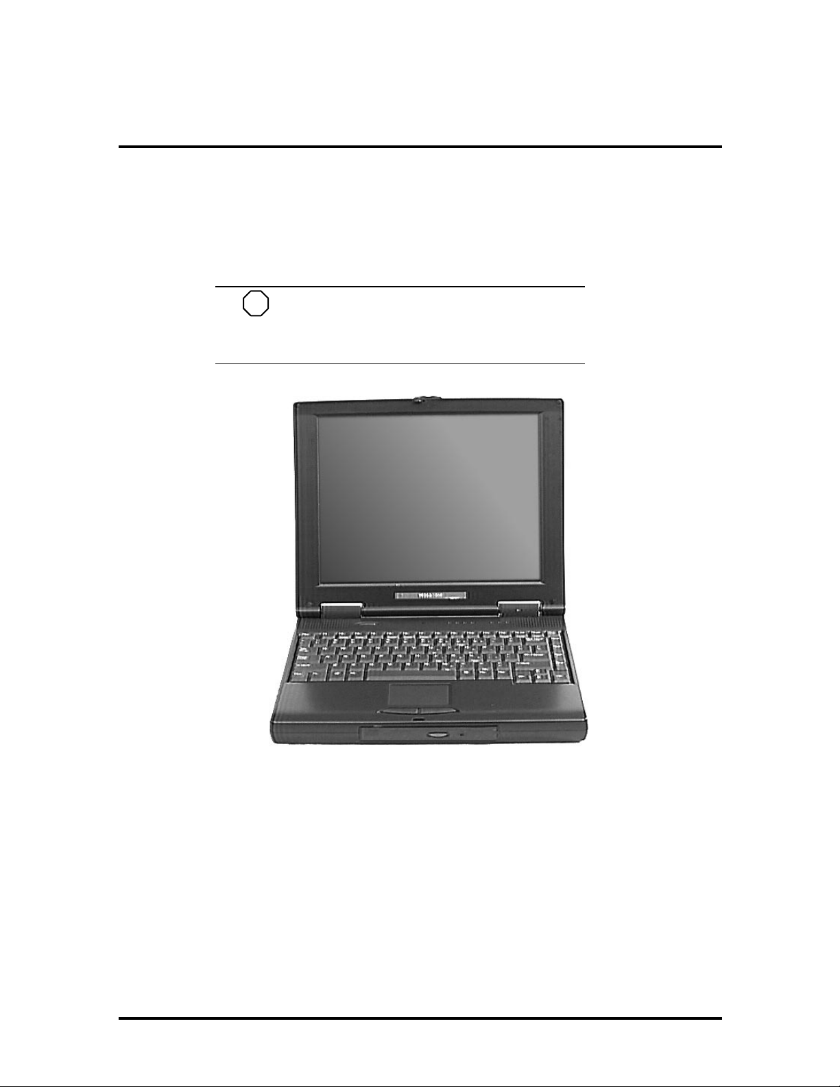
The NEC Versa 5000 Series notebook computer is lightweight, compact, and fully IBM
compatible.
NOTE
This s e rvic e manual cover s only t he NEC
Versa 5060 and 5060X models. All figur es in this
manual reflect t hese mode ls.
Figure 1-1 NEC Versa 5000 Series Notebook
This section of the manual provides system configuration information, including an overview of hardware and interface component s. See the following t able for a syste m-specific
breakdown of the hardware.
1-2 Technical Information
Table 1-1 Model Configurations
Feature NEC Versa 5060 NEC Versa 5060X
CPU Int el P entium® with
MMX technology
P55CLM/166 MHz
On-Boar d DRA M 16-MB 16-MB + 16-MB
Video M em or y 2-MB 2-MB
Hard Disk Drive 1.6 GB 2.1 or 3.2 GB
CD-ROM Reader 20X CD ROM Reader 20X CD ROM Reader
Color LCD 12.1” Super VGA
(SVGA),TFT Color
Display
Intel P entium® with
MMX technology
P55CLM/166 MHz
installed in slot
13.3” Ex tended
Graphics Array
(XGA),TFT Color
Display
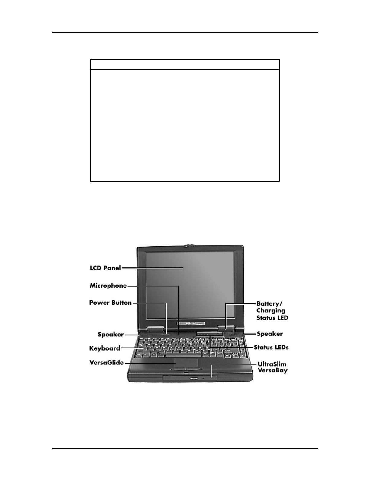
HARDWARE OVERVIEW—FRONT
Take a moment to become familiar with the location and funct ion of controls located on
the front of the system.
Figure 1-2 Location of Controls on the Front of the NEC Versa 5000

Technical Information 1-3
Liquid Crystal Display (LCD)
The LCD operates with the NeoMag ic NM2160 controller. The co nt ro ller support s XGA
and SVGA, uses a 64-bit accelerat or with a Peripheral Component Interco nnect (P CI ) interface. The LCD also supports VESA timing.
The NEC Versa 5060 LCD features the following:
12.1-inch Super Video Graphics Array (SVGA) TFT high-resolution active
matrix SVGA color displ ay
0.3075 mm dot pitch
18-bit digital interface
800 x 600 resolution
65,536 colors.
The NEC Versa 5060X LCD features the following:
13.3-inch Extended Graphics Arra y (XGA) TFT high-resolution active mat rix XG A color disp lay
0.264 mm dot pitch
18-bit digital interface with LVDS
1024 x 768 resolution
65,536 colors.
Additional LCD panel feat ures:
Power LED that indicates the current po wer stat us. This LED is visible with the LCD
panel opened or closed.
Another video feature includes a CRT port o n the system's rear panel that allows the user
to connect an optional monochrome or color external display to t he syste m. The computer
can support the LCD and external display simultaneously.
Power-saving features for controlling the LCD's backlighting include the ROM-based hot
key combination Fn F5, and Auto Setup power management settings. See Section 2, Setup
and Operation, for information on using these settings. In addition, the automatic LCD
status feature conserves the backlight.
1-4 Technical Information
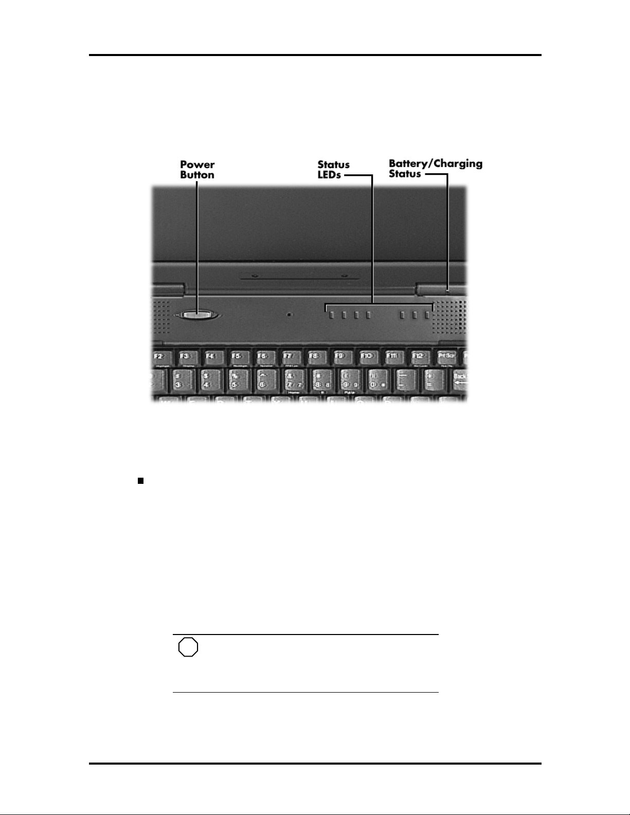
Power Button and Status LEDs
NEC Versa provides a Power button and LEDs to track system status. Descriptions of
these features follow the figur e.
Figure 1-3 LCD Status Bar and Button Locations
Power Button — The Power button is located on the chassis just below the
LCD. It turns NEC Versa 5000 power on and off. Press t he butto n to turn
power on; press it again to turn power off.
When power is on, the Power LED to the right of the Power button
lights. (The Power LED is the left-most LED in the row of LEDs.)
See “Setup Parameters” in Section 2 for information about defining
th is button as a Susp e nd/R e s ume button.
If your system is in Suspe nd mode or has gone into Save to Disk
mode, pressing the Power button puts the system in Oper ation mode.
NOTE
After turning off the system, wait 5 seconds
befo re turning it back on. This gives system components a chance to power do wn proper ly.
Technical Information 1-5
The Battery/Charging Status LED is located on the right-hand LCD
hinge and lights to indicate the following:
Green – the battery is fully charged and the system is connected to
AC power.
Amber – the battery is recharging.
Off – the AC adapter is disconnected or the battery is not installed.
A bank of status LE Ds is located on the chassis at the top of the key-
board to the right of the Power button. These LEDs are ident ified by
icons and include the fo llowing (described from left to rig ht):
The Power LED lights in the following sequence to indicate system
operation status.
– lights green when running on AC power.
– blinks green when the system is in Suspend mode.
– lights amber when running on battery power with
a charged battery.
The Power LED also warns you about a low batter y state. The
system emits a beep and t he Po wer LED behaves as follows:
– blinks amber when battery power is low.
– flashes amber when battery power is extremely
low.
The Power LED remains unlit under the following conditions:
– if the system is not connected to AC po wer and
the battery is not charged or installed.
– t he s yst e m is no t pow er e d on.
– t he system is in S ave to Disk mod e .
Hard Disk Drive – Lights when the NEC Versa 5000 writes data to
or retrieves data from the hard disk drive.
CD-ROM Reader – Lights when data is read from a compact disc in
the CD-ROM drive.
Diskette Drive – Lights when data is written to or retrieved from the
3.5-inch diskette drive.
Caps Lock – Lights when Caps Lock is on.
Num Lock – Lights when Num Lock mode is active.
1-6 Technical Information
Scroll Lo ck – Lights when the Scroll Lock is o n.
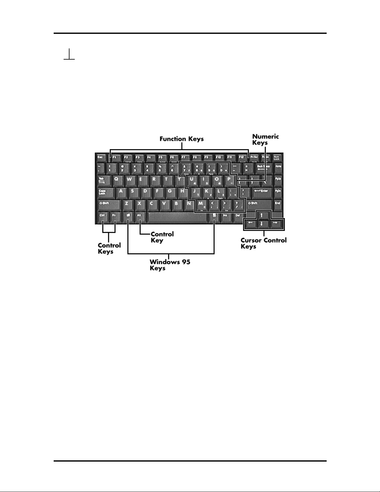
Keyboard
The built-in, 85-key keyboard (U.S.) or 79-key keyboard (UK and Germany) uses the
standard QWERTY format. The keyboard provides 12 function keys and 7 cursor control
keys, with an Fn key for ROM-based key functions. The numeric keypad is embedded in
the standard key layout.
Figure 1-4 Keyboard Layout
NEC VersaGlide
The NEC VersaGlide is a built-in mechanism that funct ions as the system’s mouse. It co ntrols the on-screen pointer (cursor). To use the VersaGlide, move your finger across the
NEC VersaGlide pad, and the cursor follows. The butto ns below t he NEC VersaGlide allow the user to select or deselect menu items. Tap and double-tap are supported on the
VersaGlide pad.
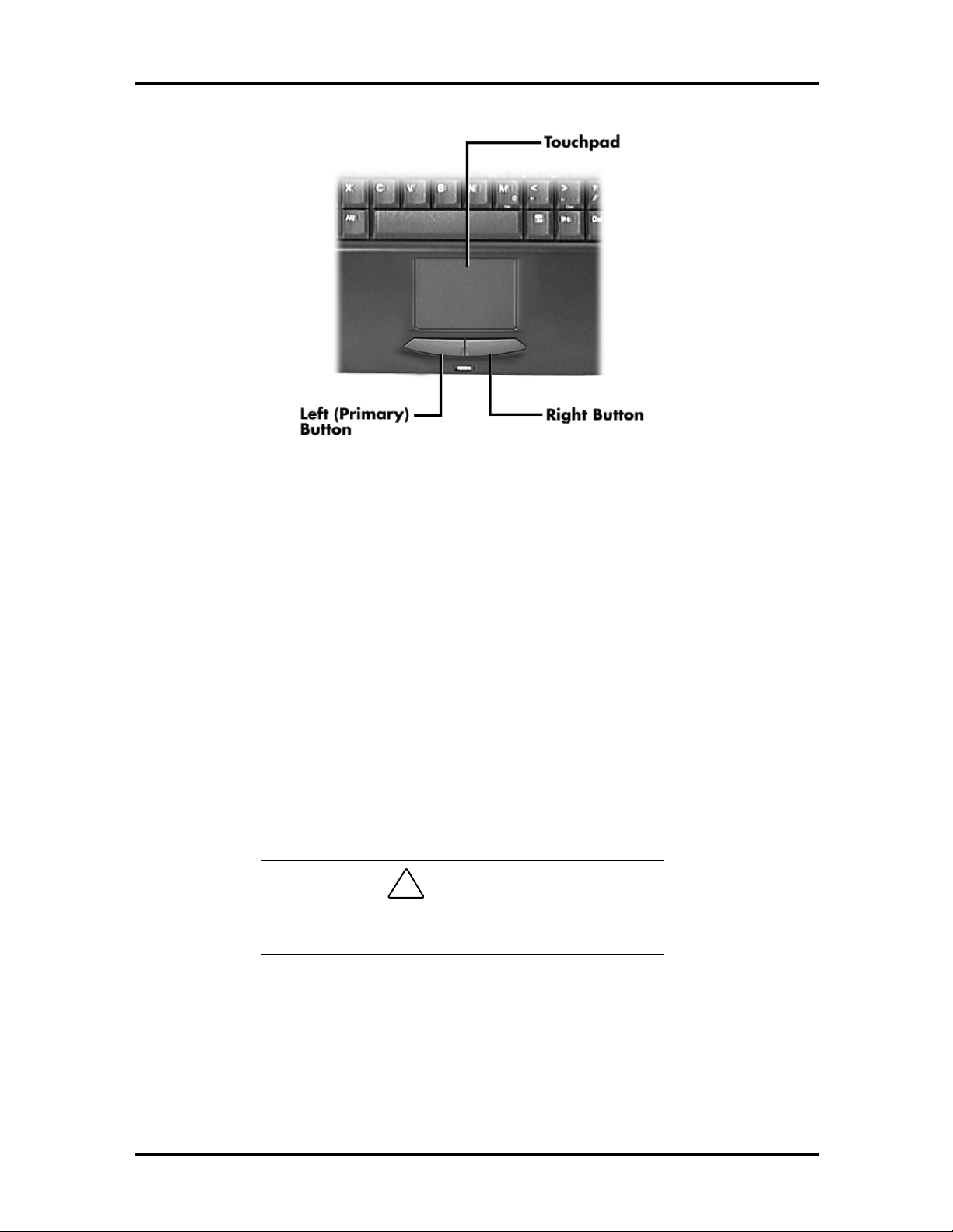
Technical Information 1-7
Figure 1-5 VersaGlide Location
UltraSlim VersaBay
A standard 1.44-M B diskette drive c omes installed in t he UltraS lim V ersaBay slot on the
front of the computer. The UltraSlim VersaBay expansion slot lets the user replace the
standard diskette drive with the 20X CD-ROM reader that also ship s with the system. In
additio n to the CD-R O M reader, the UltraS lim VersaBay accepts NEC options including a
Weight Saving Module.
HARDWARE OVERVIEW—SIDES OF THE SYSTEM
Your NEC Versa 5000 comes with many features on the left side of the system. The right
side of the system features a po rt for securing the PortBar and air vents. Keep the air vents
clear to allow for proper air circulation.
!
Do not block the air vents. Doing so can damage the
system by causing it to overheat.
CAUTION
1-8 Technical Information
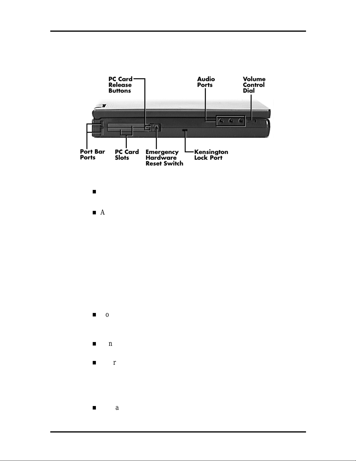
The features found on the left side of the system are shown in the following figure.
Descriptions follow the figure.
Figure 1-6 Left side features
PC Card Release Butto ns — Press the Release button when you want to
re move an installed PC card.
Audio Port s — Use these ports to attach your external audio opt ions, including the following:
Microphone — Connect s to an external m icro phone for monophon ic
recording or amplification through the unit. Plugging in an external
microp hone disables the bu ilt-in mic rophone.
Stereo Line In — Lets you use another audio system, like a home
stereo, as an input so ur ce. Use a cable to connect to the Line-Out port
on the other audio system to record or pla y.
Headphones — Lets you plug in stereo headphones or powered
speakers.
Volume Control Dial — Turn th e volume control di al clockwise to increase speaker volume, o r co unt er-clockw ise to decr ease speaker volume.
Kensington Lock Port — Use this port for added security by att aching a
Kensington Lock.
Emergency Reset Switch — This recessed switch lets you restart your
system. Use a pointed object , like a str aightened paper clip, to push in
the Reset sw itch. Do not use a pen or pencil to push the reset switch.
Use this button only if your system locks up, fails to respond to keystrokes, or fails to respond to the power button.
PC Card Slots — Two PC card slots let you insert one or two Type II PC
cards, or one Type III PC card.
Technical Information 1-9
PortBar Port — Use these port s to secur e t he Port Bar. A matching Port-
Bar port is located on the right side of the system. Two others are located
on the back.
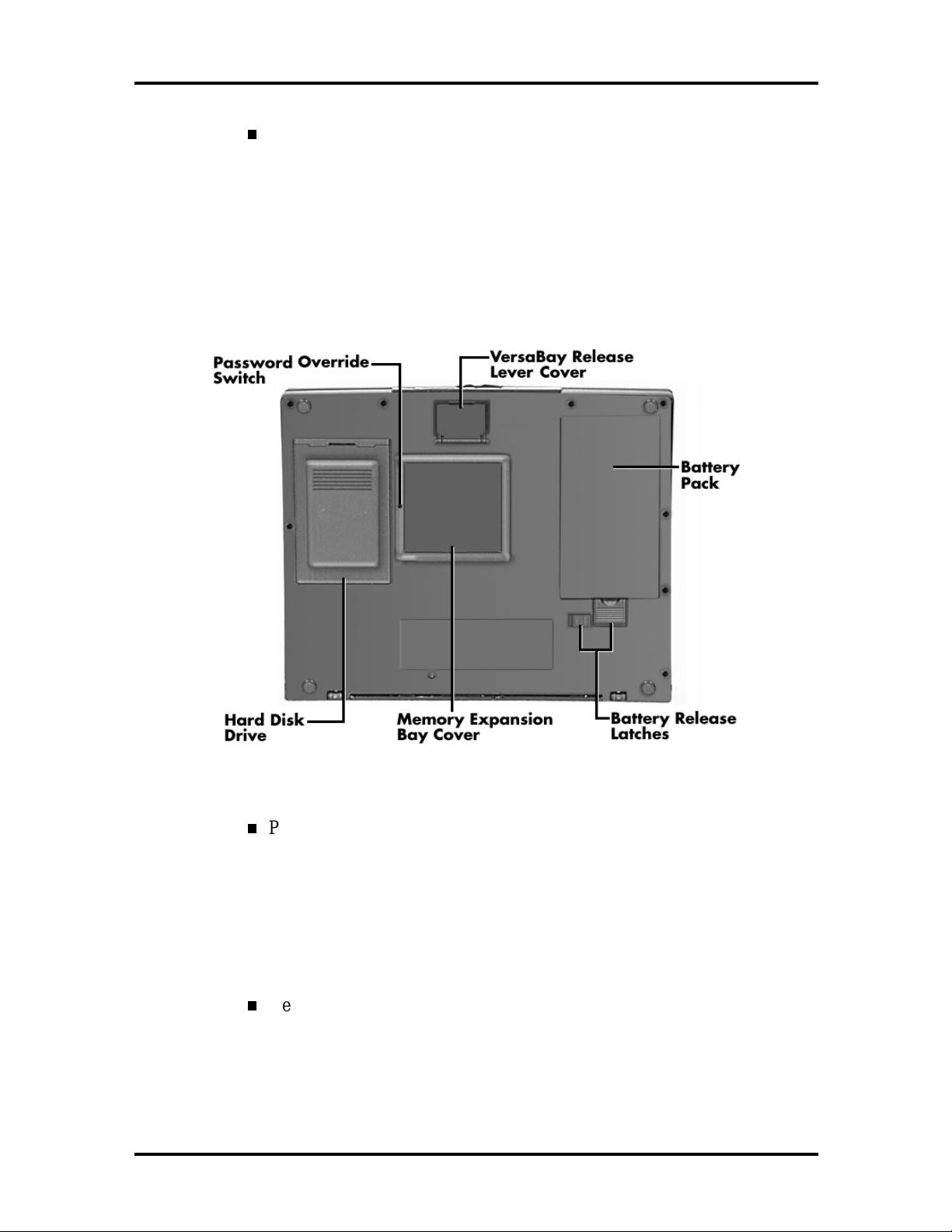
Around the Bottom of the System
The bottom of the NEC Versa 5000 is the location of the system’s memory module sockets, password overr ide switch, battery pack release latches, Ver saBay release lever and
hard disk drive bay, a s desc ribed next.
Figure 1-7 Bottom of the system
Password Override Switch — This recessed switch removes any settings
that you made in the Setup utility, including your system password.
To remove your password, power on your system. Use a pointed object,
such as a straightened paper c lip, to push in the switch. Power off, and
then power on to restart your computer. Go into the Setup utility and set
a new pass wor d. Reset a ny other syste m se tt ings t hat yo u may have
changed.
VersaBay Release Lever Co ver — Open t he re lease lever cover to access
the VersaBay Release Lever. P ushing the lever towards the front of the
system releases t he device currently installed in the VersaBay.
1-10 Technical Information
NOTE
Opening the VersaBay Release Le ver Cover
immediately puts the system into Suspend mode.
After installing the VersaBay device, press the
Power but t on to resume t he s ystem from Susp end.
Battery Pack — A Lithium-Ion (Li-Ion) rechargeab le battery pack comes
installed in t his ba y on t he bot tom o f the NE C Versa.
Battery Release Latches — Lets you remove the battery pack installed in
the bat t er y ba y.
Memory Expansion Bay Cover — Pop open the protective cover to ac-
cess two RAM expansion sockets for small outline double inline memory
modules (S O -DIMM).
Hard Disk Drive — A removable hard d isk d rive ships standa r d with
your system and is located on the bottom of the unit. Depending on your
configuration, this bay contains a 1.6-, 2- or 3-gigabyte (GB) har d disk
drive. (Chapter 4 describes how to remove this drive.)
The drive letter assigned to 1.6- GB and 2-GB hard drives is C:. If your
system ships with a 3-GB drive, it is partitioned into two drives. Drive
letters are C: and D:.
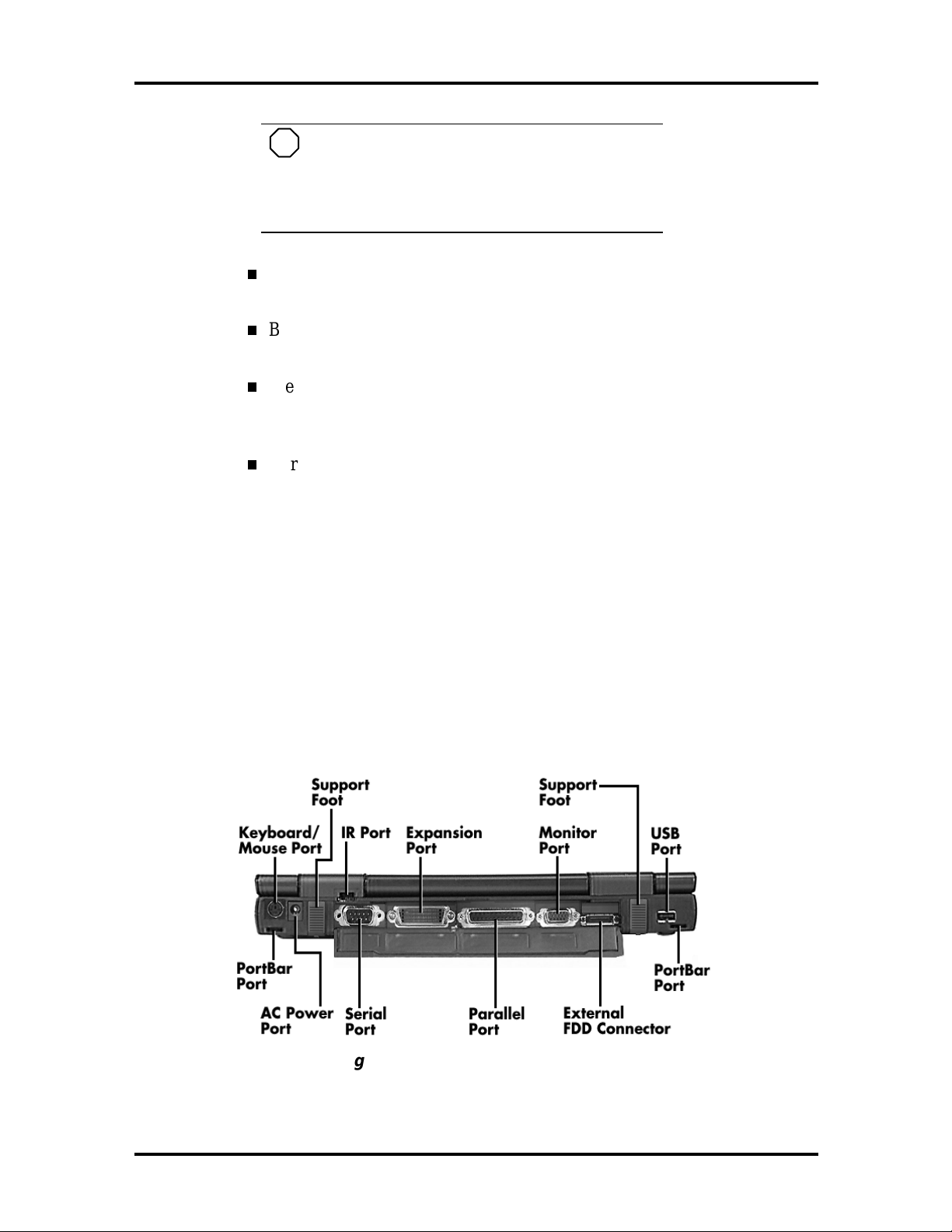
Around the Back of the System
System ports for connecting your NEC Versa 5000 to optional devices (like a printer or
external monitor) are located on t he back of the system. For an understanding o f each feature, see the descript ions that fo llow the figure.
Figure 1-8 Back system features

Technical Information 1-11
Keyboard/Mouse Port — Use the standard PS/2 port to connect an exter-
nal PS/2-style mouse or a PS/2-style keyboard to the system.
Support Feet — Slide the two support feet down from the back of the
unit to tilt your system forward for more comfortable keyboard acce ss.
Infrared (IR) Port — Use this port to transfer files between your NEC
Versa and an IR-equipped desktop or notebook computer. You can also
print to an IR-equipped printer without using cables.
Expansion Port — Use this 120-pin port to connect to the NEC PortBar
5000.
Monitor (Video) Port — Use this 15-pin port to attach an external
monitor to your NEC Versa 5000. You can run the LCD display and the
external monitor simultaneously or run either alone.
USB Port — Use this port to connect a USB device or devices to your
NEC Versa system.
PortBar Port s — Use these po rts to secure the optional PortBar. PortBar
ports are located on the back and sides of the syst em at each end.
External Diskett e Dr ive Connect or — Co nnect the External Diskette
Drive cable that came with your system to this port. Us ing the FDD connector frees up the VersaBay for installing the 20X CD-ROM reader.
Parallel Port — Use this 25-pin port to connect a parallel printer or other
parallel device. This port provides ECP mode support. The ECP standard
provides you with a greater transfer speed than t he convent ional para lle l
port. It also supports bi-directional and uni-directional protocols.
Serial Port — Use this 9-pin port to connect an external modem or other
serial device.
AC Power Port — Lets you attach the NEC Versa 5000 to the AC power
source using the AC adapter t hat co mes with your syst em. Keep the system connected to AC power whenever possible to keep t he battery pack
and internal CMOS battery charged.
HARDWARE OVERVIEW—INTERNAL COMPONENTS
Review the following sections for a description of the system’s internal hardware.
Battery Pack
The system uses a rechargea b le Lit h iu m-Ion (Li-Ion) batt er y as its t r ansient power source.
The ba tt e ry pack installs in the compa rtme nt next to the Ult raS lim VersaBa y on t he bottom
of the NEC Versa.

1-12 Technical Information
Hard Disk Drive
A standard 2.5-inch 1.6-GB 9.5 mm, 2.1-GB 12.7 mm or 3. 2- GB 12.7 mm hard disk drive
ships with the system.
Diskette Drive
The inter changeable 3. 5-inc h 1.44 MB d iskette drive in s ta lls in the front of the syste m in
the UltraSlim VersaBa y slot.
20X CD-ROM Reader
A 20X CD-ROM reader ships with the NEC Versa 5000. The interchangeable twentyspeed CD-ROM reader featur es the latest in CD-ROM technology. It inst alls in the front of
the system in the UltraSlim VersaBay slot.
CPU Board
The CPU board is located between t he Ma in boar d and Fan/Heat S ink asse mb l y. The CPU
boa rd is part of a subassembly, which includes a heat sink, fan a nd the C PU bo ard.
Audio Board
The audio board provides the NEC Versa s yst em with its audio capabilities via line-in/ lineout jacks, and headphone/microp hone jacks. I t is situat ed on top of the main board. Audio
board integrates the following features:
ESS Technology Plug and Play suppo rt
ES1869A
Integrated Music Synthesis, ESFM™ and Stereo Digital to Analog Converter
(DAC ) FM Synt hesizer
16 bit Stereo CODEC
4.0KHz to 44.1KHz Sampling Rat e
7 Channel Mixer.
Main Board
The system Main board contains peripheral subsystems including serial, parallel and video
ports, and CPU. It is located underneath the keyboard. Refer to Appendix A for a list of
connectors.

Technical Information 1-13
Bridge Battery
The bridge battery saves the memory contents and system status for up to 5 minutes while
in Suspend mode. It is connected to the Audio board via connector P11. The AC adapter
maintains voltage in the bridge battery when the system is powered on or off. The bridge
battery stores 3.6 Volts, 70 mAH.
SYSTEM MEMORY
The CPU board provides 16 MB (3.3 V SO-DIMM) of standard RAM.
Optional SO-DIMMs with a value of 16-MB, 32-MB and 64 MB can be added to increase system
memory Versa 5060/5060X: Maximum 80-MB, Versa 5080/5080X: Maximum 144-MB.
In addition, 256-KB of read-only memory (ROM), 1 x 28F020, enables the system BIOS to be flashed.
The system provides 2 MB of video RAM (50-ns HyperPage mode, self-refresh).
The following Cache RAM is provided:
L1: 32 KB (Internal Pentium)
L2: 256 KB write back (External).
Memory Map
The system supports system and video shadowing, both controlled through complementary
metal oxide semiconductor (CMOS). The system supports BIOS as a cacheable area with
write protection. Table 1-2 lists the system's memory map.
Table 1-2 Memory Map
Memory Space Size Function
0000000h-009FFFFh 640 KB DOS Applications & Optional Memory
Space Gap
00A0000h-00B7FFFh 96 KB Video (VGA) Graphic s M emor y
00B8000h-00BFFFFh 32 KB Text Mode Memor y ( S MM S pac e)
00C0000h-00C7FFFh 40 KB Video (VGA) BIOS
00C8000h-00D7FFFh 128 KB PCMCIA Window and USB (Extended
Memory or Upper Memory Bloc k)
00D8000h-00DFFFFh 32 KB Boot Block Code CMOS Save Ar ea
00E0000h-000FFFFFh 64 KB System BIOS ROM
To -00FFFFFFh 16 MB Total Base Memory
To -FFFEFFFFh 80 MB Total Expansion Memory

1-14 Technical Information
SYSTEM VIDEO
The system's LCD operates using the NeoMagic NM2160 Controller. Video signals travel
from the controller through the system's 15-pin D-SUB connector using 3.3/5 volts.
System video integrates a PCI-bus interface. T he system ships with 2 MB Video RAM
(VRAM). It supports video modes up to 1024 x 768 with 64K colors in LCD mode.
See Appendix B for a list of Video modes.
PARALLEL INTERFACE
The system' s parallel interface integrates National Semiconductor’s PC87338 chip with a
25-pin D-subconnector. T he port is located on the system's rear panel.
The modes of operation available for a PC87338 chip are:
compatibility mode
nibble mo de
byte mo de
Extended Capabilities Port (ECP)
The user selects between t hree par allel interface modes using Auto Set up. T hese include
unidirectional, bidirect ional, extended or enhanced. Unidirectional mode sends data out put
from the standard ISA port only. Bidirectional mode sends data using the standard ISA
port or PS/2 technology. Enhanced mode enables high speed data transmission to occur
using either the unidirectional or bidirectional modes.
The default parallel port address is 378h and the interrupt level is IRQ07. Pin locations for
the pa r alle l interface ar e listed in Appe ndix A.
SERIAL INTERFACE
The RS-232C serial port is a 9-pin connector on the system’s rear panel. The serial port
consists of a 16550A and 16450 compatible serial port controller with a programmable
baud rate up to 115,200 bps. The serial port connects an RS-232C device or an external
modem. The default serial port address is 3F8h and the interrupt level is IRQ04.

Technical Information 1-15
NEC VERSA CHIP SET
Refer to Table 1-3 for a quick summary of chip t ypes used in the system. See the Abbreviations section at the beginning of this manual for a translation of chip technologies.
Table 1-3 NEC Versa Series Chip Types and Technologies
Chip Manufacturer Description Technology
Intel P entium
P55CTT80503
82C700(FireStar) Opti FireStar System Controller 432--pin BGA
82C861(FireLink) Opti USB Controll er 100-pin TQFP
N28F002BC-90 Intel 256k x 8 Flash ROM 32-pi n P LCC
NM2160 NeoMagic VGA Controller 208-pin FQFP
PC97338 National
H8/3434 Hitachi Keyboard Controller 64-pin TQFP
PCI1131 Texas Instruments PC Car d Controller 208-pin QFP
ES1869 ESS Technologies Sound Control ler 100-pin PQFP
Intel 166 MHz CPU 320-pin TCP
Semiconductor
Diskette Controller, IDE,
Para llel Inter face
100-pin TQFP
Intel Pentium P55CLM Microprocessor
The 166 MHz Intel Pentium microprocessors with MMX technology used in the NEC
Versa Series computer is built on Intel’s advanced 2.5V B iCMOS s il icon t echno log y. The
CPU has on-chip dual-processing, a local multiprocessor interrupt controller, and power
management features. NEC adopted the chip specifically for its pipelined Floating Point
Unit (FPU), and local interrupt management.
FireStar System Controllers
NEC implements Opti’s 64-bit single chip controller (82C700) for the NEC Versa 5000
Series not e book ’ s s ubsystems inc luding the D RAM controlle r, S eco nd Leve l C ache C ontroller and PCI Bus interface. T he FireStar P CI set featur es inc lude:
3.3V EDO DIMM (70-ns) support
direct mapped organization write-back po licy
fully synchronous 33 MHz PCI bus inter face.
USB Controller
The Opti 82C861 FireStar chip is a PCI USB contr oller. The controller based on Open HCI
standard and supports hot plug in and unplug.

1-16 Technical Information
The chip features include:
USB Specification R ev 1. 0
Open HCI Specification Rev 1.0a.
256K X Flash ROM
The N28F002BC-90 flash ROM is a 32-pin, plastic lead chip carrier (PLCC). The chip allows easy updates to the system's BIOS if needed. More specifically, the ROM is flashed
electronically, installing the latest BIOS revisions to the system. It is possible to reprogram
the BIOS up to 100,000 times. See Section 2, Setup and Operatio n, for BIOS update pro cedures.
The N28F002BC-90 provides the system upgrade capability as well as the following:
256 KB memory
Quick-Pulse Programming Algorithm
150 nanoseconds (ns) maximum access time
ET OX Nonvolatile f las h t ec h nolog y
CMOS low power co nsumption
ROM BIOS
The system uses a Flash ROM kno wn as the system's ROM BIOS to st or e machine language programs. The BIOS size is 256 KB, consisting of the system utility (for PC cards,
Auto Setup), system BIOS, video BIOS, and power management.
The BIOS programs execute t he po wer-o n self-t est (POST), initialize CPU cont ro llers, and
interact with the LCD indicator panel, disket te drive, hard drive, communication devices
and peripherals. The syst em BIOS also contains Auto Setup and provides VGA contr oller
support. The ROM BIOS is copied into RAM (shadowing) for optimum performance.
The ROM BIOS contains both the system and video BIOS. The system BIOS is locat ed in
the upper portion of the device; video BIOS is located in the lower portion. System BIOS
is located between 00F0000h-000FFFFFh.
The BIOS often changes after the pro duct release to provide enhanced features or bug
fixes. To acquire the latest BIOS release, the ROM is flashed electronically allowing the
BIOS update to occur without removing the ROM. See Section 2, Setup and Oper ation, for
BIOS upgrade procedures.

Technical Information 1-17
VGA Controller
The NeoMagic NM2160 is a PCI 128-bit Graphics Accelerator. The integrated programmable linear address featur e accelerates the graphics user interface (GUI) performance.
The controller also supports Hardwar e Mult imedia and VESA interface st andards. The
controller provides advanced po wer manage ment that helps to minimize po wer usage in
the following modes:
normal operat ion
Standby (sleep) mode
panel off power saving modes.
Parallel Interface
The PC87338VJG chip is a 100-pin Thin Quad Flat Plast ic (TQFP) chip. The controller
changes 8-bit parallel data into serial data and writes the data to the diskette. Conversely,
the serial data is transmitted fro m the diskette into parallel data, where it remains unt il the
read operation takes p lace.
Additional PC87338VJG chip operations include:
ISA compatibility
low-power CMOS with enhanced power-down mode
Keyboard Controller
The keyboard controller (H8/3434) supports a PS/2-style keyboard and, mouse. Refer to
Appendix A for keyboard interface connecto r pin assignments.
When data is written to the output buffer, the controller generates an interru pt , and request s
the CPU to receive the data. The controller automat ically adds an even par it y bit to the data
sent and waits for a response. T he de vice must acknowledge that the data was successful l y
received by sending a response to t he controller for each byte of data rece ived.
PC CardBus Controller
The Texas Instruments PCI1131 controller interfaces with the PCI bu s, PC CardBus socket
and configuration regist er s to prov ide:
compliant with PCI 2.1 and 1995 PC card standards
CardBus slots with hot insertion and removal
independent Read and Write buffers for each d irection
burst transfers to maximize data throughput on the PCI CardBus bus.
1-18 Technical Information
Sound Integrated Circuit
The ESS Technologies chip set ES1869A provides dynamic audio circuitry with the following:
Audio digital processor
Plug and Play support
High-performance 16-bit Stereo Codec
Full-duplex operat ion for simultaneous r ecord and playback
Analog joystick quad timer and digital joystick support.
Interrupt Controllers
Using interrupts, it is possible to change the system’s code sequence. To change the sequence, reassign the interrupt-levels. Fifteen interr upts can be used with a cascade connection of two 82C59 interrupt controllers.
Interrupt-level assignments 0 through 15 are listed in Table 1-4, in order of decreasing
priority.
Table 1-4 Interrupt Controllers
Channel Device
IRQ00 System Timer
IRQ01 Keyboard
IRQ02 Sec ond Interrupt Controller
IRQ03 CO M 2 (i nternal IR port)
IRQ04 CO M 1 (i nternal serial port)
IRQ05 Sound Chip, MIDI (default)
IRQ06 F loppy Disk Drive Controller
IRQ07 LPT1 Default (internal pri nter port)
IRQ08 Real Time Clock
IRQ09 USB
IRQ10 Not Used
IRQ11 CardB us cont r oller
IRQ12
IRQ13 Co-Processor
IRQ14 Pr imary IDE (Hard Disk Drive)
IRQ15 Sec ondar y IDE (CD-ROM)
Inter nal Glide Pointer or External
PS/2 Mouse
Technical Information 1-19
POWER MANAGEMENT OVERVIEW
Power Management in the NEC Ver sa lets you co nserve energ y, save bat tery power, extend the life of your LCD backlight, and protect against data loss due to low battery power.
Set some features to function automatically or activate them manually with the keyboard or
a button. It is wise to keep Power Management features enabled, even w hen using AC
power.
The system ships with many power-saving features already enabled. See the following table.
Table 1-5 Automatic Power-Saving Features
Default
Device
Idle Mode On Idl e m ode sl ows down the CPU during brief
Standby Timeout 4 minutes Specifies how long the system is in Idle mode
Auto Suspend
Timeout
Hard Disk Timeout 2 minutes
Video Timeout 2 minutes Shut s off video screen after the timeout specified
CD-ROM Timeout 45 second s Specifies how long the CD- ROM reader remains
Timeout
10 minutes T his setting specifies how long the system
Comment
periods when the system is not busy.
before enteri ng Standby m ode. Standby turns off
various system devices including the screen.
remains in Standby mode before entering
Suspend.
Stops the hard disk motor when the hard disk is
not accessed for the specif ied timeout.
elapses.
inactive bef or e being turned off.
NOTE
In Windows 95 systems, power management
settings under Windows override the settings established in Setup.
You can change the timeout period for any of the devices using Setup. See Section 2 for
Setup utility procedures.
Use the
FnF7
key combination to set the power management level you can toggle between
Highest Performance, Longest Battery Life, Custom Power Management, and Off. Default
values change depending on the type of power management you use.
 Loading...