

NEC USB Hub and Audio User Manual

203 Eng Fr Cndn manual 12/21/98 11:19 AM Page 1
MultiSync
MultiSync
IntelliBase
IntelliBase
USB Hub
USB Hub
and Audio
and Audio
®
®
™
™
User’s Manual
User’s Manual

Index
Table des matières
Contenu 31
Démarrage rapide 32-50
Tableau de commande IntelliBasemc51
Commandes 52
Caractéristiques 54
Dépannage 55
Références 56
Garantie limitée 57
203 Eng Fr Cndn manual 12/21/98 11:19 AM Page 2
Contents 1
Quick Start 2-20
IntelliBase™Control Panel 21
Controls 22-23
Specifications 24
Troubleshooting 25
References 26
Limited Warranty 27
Safety Precautions and Maintenance
203 Eng Fr Cndn manual 12/21/98 11:19 AM Page 3
IMPORTANT
The lightning flash with arrowhead, within an
equilateral triangle, is intended to alert the
user to the presence of uninsulated
“dangerous voltage” within the product’s
enclosure that may be of sufficient magnitude
to constitute a risk of electric shock to persons.
FOR OPTIMUM PERFORMANCE, PLEASE NOTE THE FOLLOWING WHEN
CAUTION: TO PREVENT THE RISK OF
ELECTRIC SHOCK, DO NOT REMOVE COVER
(OR BACK). NO USER- SERVICEABLE PARTS
INSIDE. REFER SERVICING TO QUALIFIED
SERVICE PERSONNEL.
The exclamation point within an equilateral
triangle is intended to alert the user to the
presence of important operating and
maintenance (servicing) instructions in
the literature accompanying the appliance.
SETTING UP AND USING THE MULTISYNC®INTELLIBASE™WITH USB AUDIO:
Read Instructions — All the safety and operating instructions should be read before the appliance is operated.
Retain Instructions — The operating instructions should be retained for future reference.
Heed Warning — All warnings on the appliance and in the operating instructions should be adhered to.
Follow Instructions — All operating and use instructions should be followed.
Water and Moisture — The appliance should not be used near water – for example, near a bathtub, washbowl, kitchen
sink, laundry tub, in a wet basement, or near a swimming pool, etc.
Outdoor Use — Warning: To reduce the risk of fire or electric shock, do not expose this appliance to rain or moisture.
Location — The appliance should be installed in a stable location. Do not use the monitor while the base is removed.
Ventilation — The appliance should be situated so that its location or position does not interfere with its proper ventilation.
For example, the appliance should not be situated on a bed, sofa, rug, or similar surface that may block the ventilation
openings; or placed in a built-in installation, such as a closed bookcase or cabinet that may impede the flow of air through
the ventilation openings.
Heat — The appliance should be situated away from heat sources such as radiators, heat registers, stoves, or other
appliances (including amplifiers) that produce heat.
Power Sources —
described in the operating instructions or as marked on the appliance.
Power-Cord Protection — Power-supply cords should be routed so that they are not likely to be walked on or pinched by
items placed upon or against them. Pay particular attention to cords at plugs, convenience receptacles, and the point where
they exit from the appliance.
Image and Sound — Adjust the sound output for optimal image and speaker clarity.
Grounding or Polarization — Precautions should be taken so that the grounding or polarization means of an appliance
is not defeated.
Cleaning — The appliance should be cleaned only with a polishing cloth or a soft dry cloth. Never clean with furniture wax,
benzine, insecticides or other volatile liquids since they may corrode the cabinet.
Non-Use Periods — The power cord of the appliance should be unplugged from the outlet when left unused for a long
period of time.
Object and Liquid Entry — Care should be taken so that objects do not fall and liquids are not spilled into the enclosure
through openings.
Damage Requiring Service — The appliance should be ser viced by qualified service personnel when:
• The power-supply cord or the plug has been damaged.
• Objects have fallen, or liquid has been spilled into the appliance.
• The appliance has been exposed to rain.
• The appliance does not appear to operate normally or exhibits a marked change in performance.
• The appliance has been dropped or the enclosure damaged.
Servicing — The user should not attempt to service the appliance. Servicing should be referred to qualified service personnel
or returned to the dealer or call the NEC TECH service line for assistance at 1-800-632-4662.
Use the supplied AC adapter. The appliance should be connected to a power supply only of the type
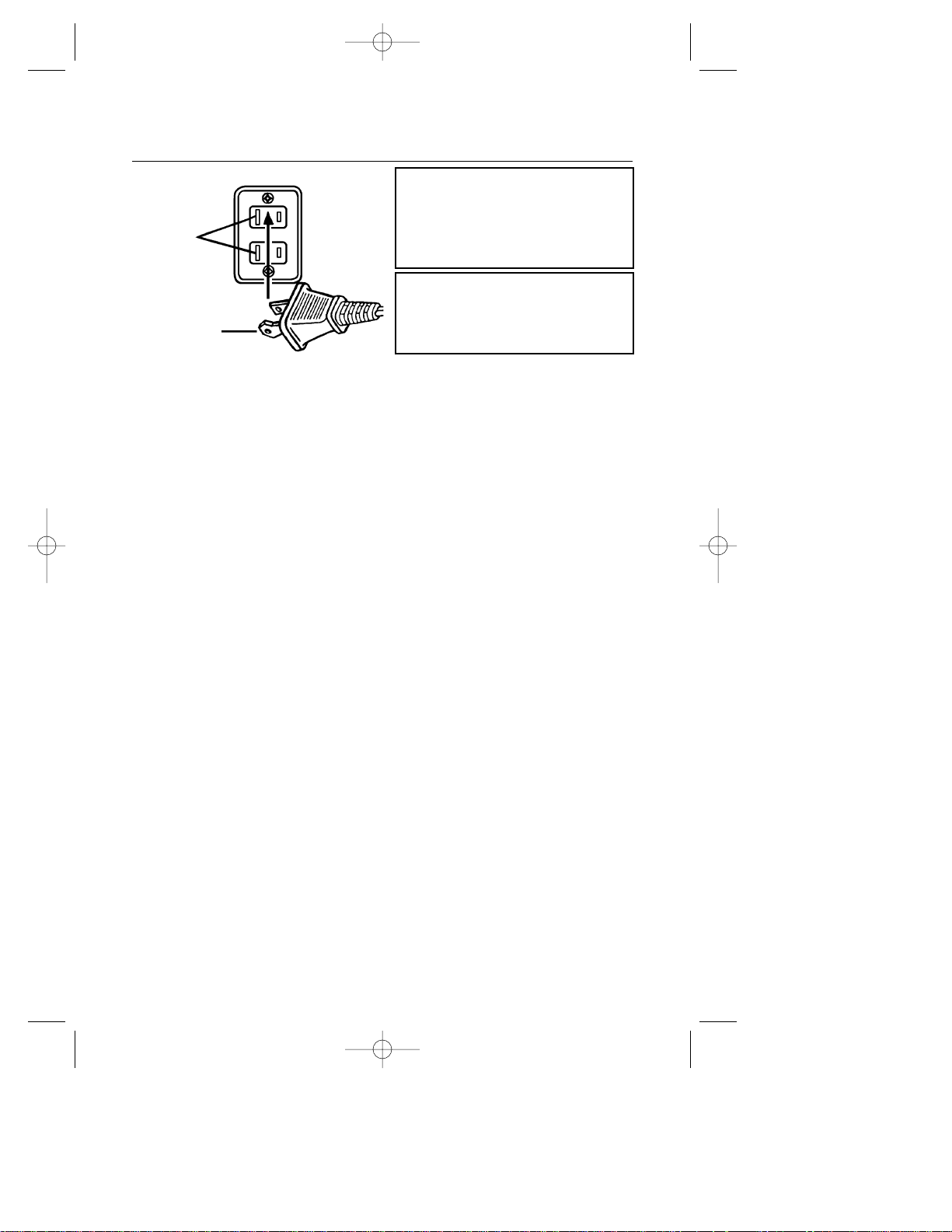
Connecting the Power Cord
AC Wall Socket
Long slot
is neutral
(ground) side.
Insert the wide
blade into the
ground side slot.
CAUTION: To prevent electric shock do not
use this (polarized) plug with an extension
cord, receptacle or other outlet unless the
blades can be fully inserted to prevent blade
exposure.
203 Eng Fr Cndn manual 12/21/98 11:19 AM Page 4
WARNING
TO REDUCE THE RISK OF FIRE OR ELECTRIC
SHOCK, DO NOT EXPOSE THIS APPLIANCE
TO RAIN OR MOISTURE.
The FCC Wants You to Know
1. Use the attached specified cable with the MultiSync
®
IntelliBase™USB Hub and Audio so as
not to interfere with radio and television reception.
Please use the supplied power cable or equivalent to ensure FCC compliance.
2. This equipment has been tested and found to comply with the limits for a Class B digital
device, pursuant to Part 15 of the FCC rules. These limits are designed to provide reasonable
protection against harmful interference in a residential installation. This equipment generates,
uses and can radiate radio frequency energy and, if not installed and used in accordance with
the instructions, may cause harmful interference to radio communications. However, there is no
guarantee that interference will not occur in a particular installation. If this equipment does
cause harmful interference to radio or television reception, which can be determined by
turning the equipment off and on, the user is encouraged to try to correct the interference by
one or more of the following measures:
a) Reorient or relocate the receiving antenna.
b) Increase the separation between the equipment and receiver.
c) Connect the equipment to an outlet on a circuit different from that to which the receiver
is connected.
d) Consult your dealer or an experienced radio/TV technician for help.
If necessary, the user should contact the dealer or an experienced radio/television technician
for additional suggestions. The user may find the following booklet, prepared by the Federal
Communications Commission, helpful: “How to Identify and Resolve Radio-TV Interference
Problems.” This booklet is available from the U.S. Government Printing Office, Washington,
D.C., 20402, Stock No. 004-000-00345-4
MultiSync
®
IntelliBase
™
USB and
Audio
User's Manual
IntelliBase
™
US B A UD IO
Audio Management Software
Version 1.0
®
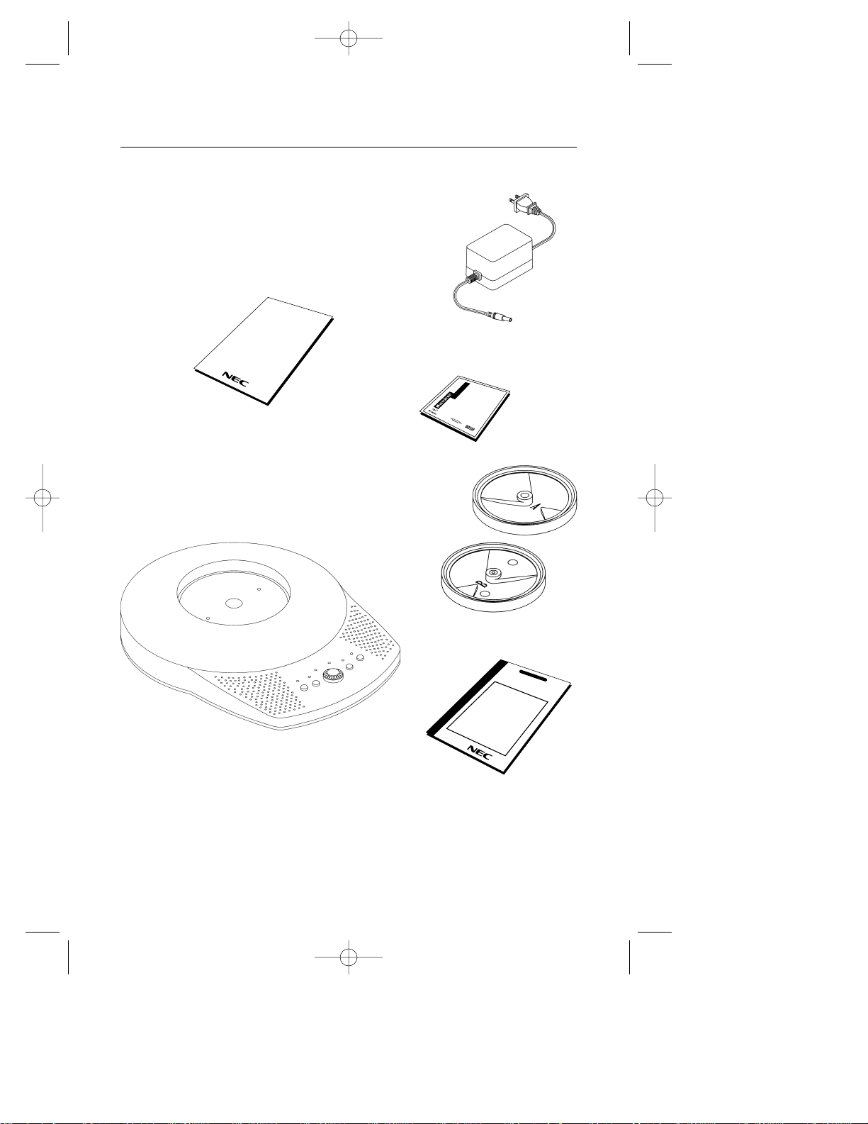
Contents
Your new NEC Technologies MultiSync®IntelliBase™USB Hub
and Audio carton box* should contain the following:
• MultiSync IntelliBase USB Hub and Audio (IB-USB AUDIO)
• AC Adapter • Adapter Plate A
• User’s Manual • Adapter Plate B
• Registration Card • CD-ROM
• Audio and USB Cable
• Screws
AC Adapter
*Remember to save your original box and packaging
material to transport or ship the MultiSync IntelliBase USB Hub and Audio.
Note: You can register your product on the Internet at
http://www.prodreg.com/nec
Registration
Card
— Important —
To help us in our continuing efforts to
better serve and support you, and to
bring you new and innovative products,
please take a few moments to register
your new NEC MultiSync monitor.
By returning this card, we confirm your
date of purchase and records the model
and serial numbers. This facilitates our
ability to process warranty claims,
especially if your original proof of
purchase is lost.
Thank you for your time and for
choosing an NEC MultiSync monitor.
THANK YOU FOR
CHOOSING AN NEC
MultiSync
®
IntelliBase
™
PRODUCT REGISTRATION
NEC MultiSync Monitors
USB Cable
Audio Cable
Adapter
Plate B
Adapter
Plate A
Screws
203 Eng Fr Cndn manual 12/21/98 11:19 AM Page 5
User’s
Manual
CD-ROM
MultiSync
IntelliBase
USB Hub and Audio
1
Quick Star t
How to attach IntelliBase™USB Hub and Audio to your
MultiSync
®
brand monitor
THE INTELLIBASE USB HUB AND AUDIO WILL ONLY WORK WITH THE
MULTISYNC BRAND MONITORS LISTED BELOW. DO NOT ATTEMPT TO
CONNECT THE INTELLIBASE WITH ANY OTHER MONITOR BRANDS.
MAKE SURE THE MONITOR IS DISCONNECTED FROM THE SYSTEM AND
IS UNPLUGGED FROM THE WALL OUTLET BEFORE ANY WORK IS DONE
ON THE MONITOR.
FOR ALL 21” MULTISYNC MONITORS
IT IS ADVISED THAT TWO PEOPLE ARE INVOLVED DURING THE ENTIRE
INSTALLATION PROCESS. ONCE THE INTELLIBASE HAS BEEN INSTALLED
ONTO YOUR 21” MONITOR, DO NOT ATTEMPT TO ADJUST THE TILT OF THE
MONITOR FROM THE BACK OF THE MONITOR UNIT. ONLY ADJUST THE TILT
FROM THE FRONT OF THE UNIT BY HOLDING ONTO THE LEFT AND RIGHT
SIDE OF THE MONITOR, TILTING EITHER UPWARDS OR DOWNWARDS. DO
NOT TILT THE MONITOR DOWNWARDS MORE THAN 5 DEGREES OR FORCE
THE MONITOR PAST THE FIRST STOP, AS THE MONITOR MAY BECOME
UNSTABLE, CAUSING POSSIBLE INJURY.
If you have any questions or comments, please contact NEC at 1-800-632-4662
To attach the IntelliBase to your MultiSync brand monitor, the original base
must first be removed. Depending on the model of your MultiSync brand
monitor, the removal procedure of the original base and the attachment of
the IntelliBase will vary. Locate the model name (located in the lower right
corner of your monitor’s bezel) of your MultiSync brand monitor in the table
below. Follow the removal procedure to detach the original base from your
monitor using the diagrams on the following pages and attach the IntelliBase
to your monitor.
2
MultiSync Monitor Model Names
Original Monitor Base
Removal and IntelliBase
Installation Instructions
MultiSync 50, MultiSync 70, XV15 and
XV15+
MultiSync XE15, XE17, XP15, XP17, XV17,
XV17+, A500, A500+, A700, A700+,
A900, E500, E700, E900, E900+, M500,
M700 and P750
MultiSync XE21, XP21, E1100, E1100+,
P1150 and P1250+
Page 3
Page 5
Page 7
203 Eng Fr Cndn manual 12/21/98 11:19 AM Page 6
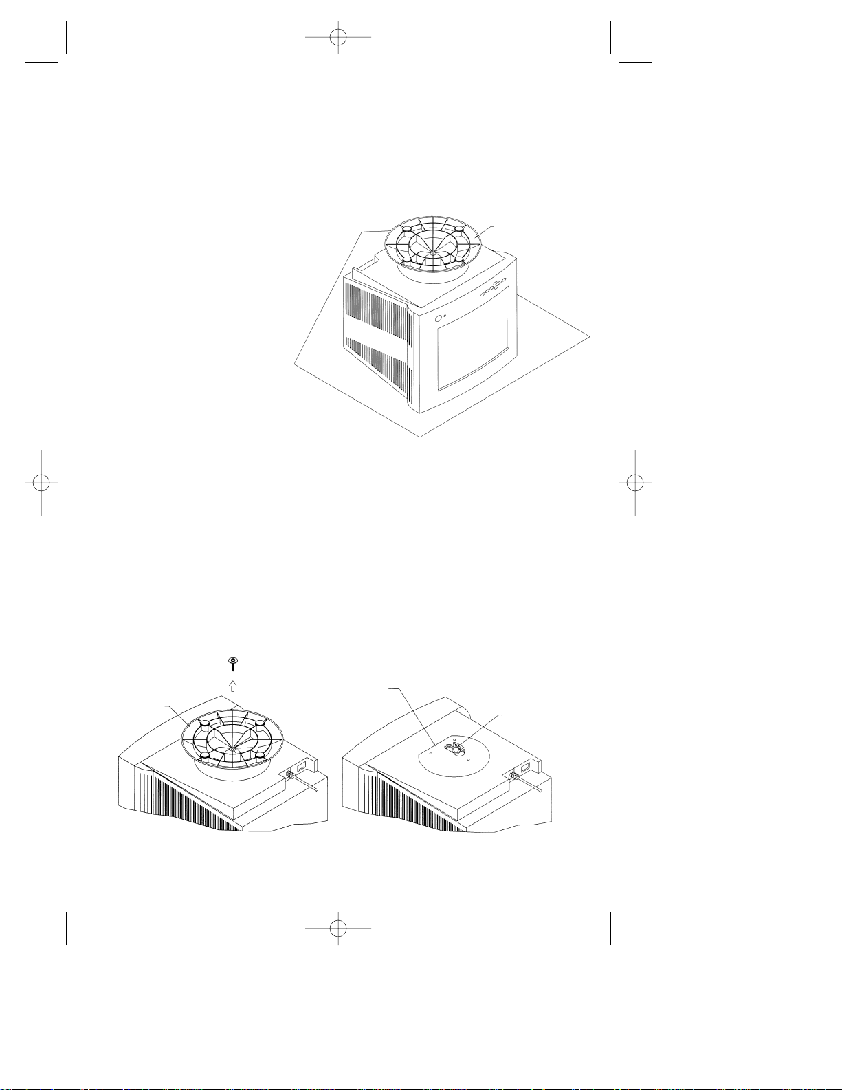
MultiSync®Monitor Model Names
MultiSync 50, MultiSync 70, XV15 and XV15+
Step 1 With the monitor
unplugged from your
system and the wall
outlet, carefully
turn the monitor
upside down on
a firm table so that
the base is facing
up as shown
in Figure 1.
Figure 1
MONITOR IN POSITION TO
REMOVE THE BASE AND ATTACH
INTELLIBASE USB HUB AND AUDIO
BASE
SWIVEL
PLATE
SPINDLE
DO NOT REMOVE SPINDLE OR
SWIVEL PLATE
BASE
203 Eng Fr Cndn manual 12/21/98 11:19 AM Page 7
Step 2 Using a Phillips screwdriver, remove the screw securing the original
base to the monitor as shown in Figure 2A. Remove and save the
original base for possible future use.
Note: Do not remove the spindle or swivel plate.
Figure 2A
3
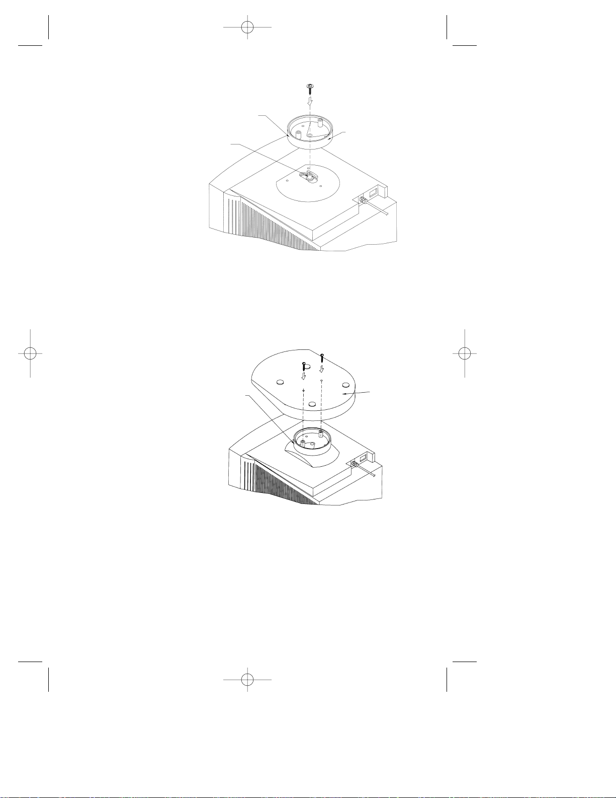
Figure 2C
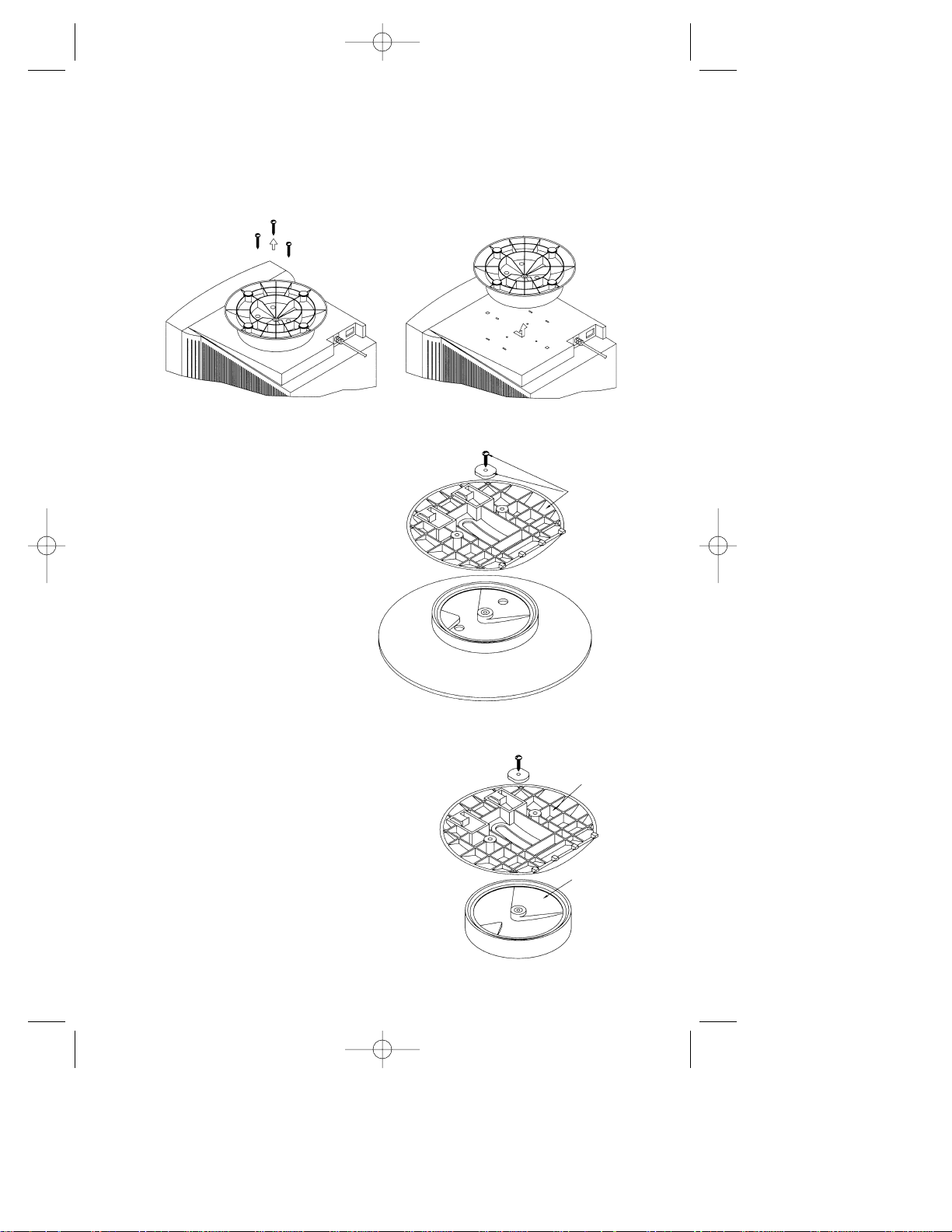
Step 3 Locate Adapter
Plate “A” that
is supplied with
the IntelliBase
™
and secure it to
the spindle using
the screw that
was removed
in Step 2
as shown in
Figure 2B.
Figure 2B
GUIDE SPINDLE
THROUGH CENTER
HOLE ON ADAPTER
PLATE (A)
ADAPTER
PLATE (A)
SPINDLE
INTELLIBASE
(BOTTOM VIEW)
ROTATE ADAPTER
PLATE UNTIL IT
ALIGNS WITH
THROUGH HOLES
ON THE BASE
203 Eng Fr Cndn manual 12/21/98 11:20 AM Page 8
Step 4 Locate the two
screws that are
supplied with
the IntelliBase
and attach the
IntelliBase to
the adapter plate
and monitor
as shown
in Figure 2C.
Proceed to Page 10 to connect your MultiSync®monitor with the IntelliBase
USB Hub and Audio to your system.
4
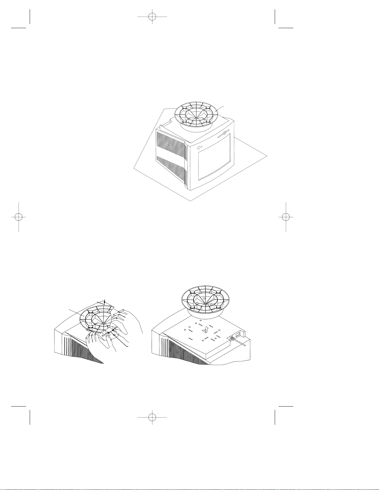
Figure 3A
Figure 1
MONITOR IN POSITION TO
REMOVE THE BASE AND ATTACH
INTELLIBASE USB HUB AND AUDIO
BASE
BASE
LOCKING
TABS
203 Eng Fr Cndn manual 12/21/98 11:20 AM Page 9
MultiSync®Monitor Model Names
MultiSync XE15, XE17, XP15, XP17, XV17, XV17+, A500, A500+ A700,
A700+, A900, E500, E700, E900, E900+, M500, M700 and P750
Step 1 With the monitor
unplugged from your
system and wall
outlet, carefully
turn the monitor
upside down on
a firm table so that
the base is facing
up as shown
in Figure 1.
Step 2 Using your thumbs, push on the locking tabs while pulling forward
and up as shown by the directional arrow in Figure 3A. This
action releases the base from the monitor. Remove and save the
original base for possible future use.
5
6
BASE
ADAPTER
PLATE (B)
NEW MOUNTING
Figure 3C
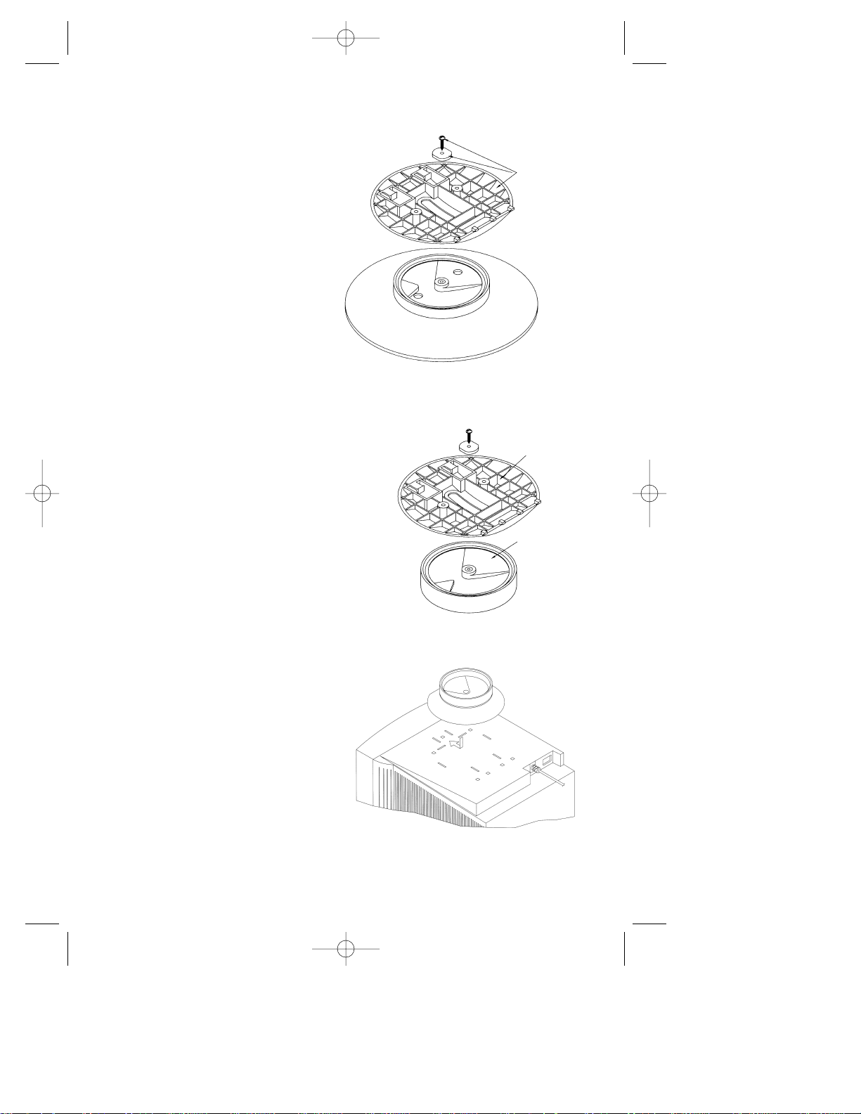
Step 5 After the adapter plate has
been attached to the base,
snap the base assembly to
the monitor. To accomplish
this, position all the locking
tabs on the base so they
mate with the holes in the
monitor. Slide the base
assembly in place as
shown in Figure 3D.
Figure 3D
203 Eng Fr Cndn manual 12/21/98 11:20 AM Page 10
Step 3 Using a Phillips
screwdriver, remove
the screw securing
the two base halves
together as shown
in Figure 3B.
Retain the screw
and black nylon
washer for use
in the next step.
Step 4 Locate Adapter Plate “B”
that is supplied with
the IntelliBase™and
secure it to the spindle
using the screw and
black nylon washer that
was removed in Step 2
as shown in Figure 3C.
ORIGINAL MOUNTING
Figure 3B
RETAIN
THESE
PARTS TO
USE IN
NEW
MOUNTING
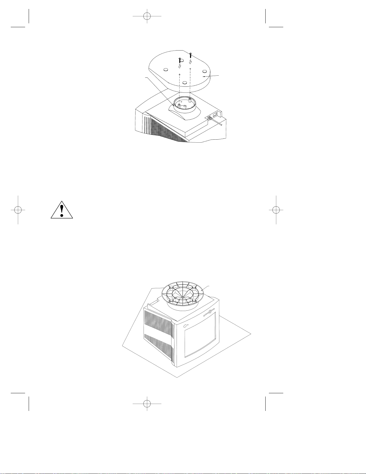
Figure 1
Step 6 Locate the two screws that
are supplied with the
IntelliBase
and attach
the IntelliBase
™
to the adapter
plate and
monitor as
shown in
Figure 3E.
Proceed to Page 10 to connect your MultiSync®monitor with IntelliBase
USB Hub and Audio to your system.
7
MultiSync Monitor Model Names
MultiSync XE21, XP21, E1100, E1100+, P1150 and P1250+
FOR ALL 21” MULTISYNC MONITORS
IT IS ADVISED THAT TWO PEOPLE ARE INVOLVED DURING THE ENTIRE
INSTALLATION PROCESS. ONCE THE INTELLIBASE HAS BEEN INSTALLED
ONTO YOUR 21” MONITOR, DO NOT ATTEMPT TO ADJUST THE TILT OF THE
MONITOR FROM THE BACK OF THE MONITOR UNIT. ONLY ADJUST THE TILT
FROM THE FRONT OF THE UNIT BY HOLDING ONTO THE LEFT AND RIGHT
SIDE OF THE MONITOR, TILTING EITHER UPWARDS OR DOWNWARDS. DO
NOT TILT THE MONITOR DOWNWARDS MORE THAN 5 DEGREES OR FORCE
THE MONITOR PAST THE FIRST STOP, AS THE MONITOR MAY BECOME
UNSTABLE, CAUSING POSSIBLE INJURY.
If you have any questions or comments, please contact NEC at 1-800-632-4662
Step 1 With the monitor
unplugged from your
system and wall outlet,
carefully turn the
monitor upside down
onto a firm table so
that the base is
facing up as shown
in Figure 1.
Figure 3E
INTELLIBASE
(BOTTOM VIEW)
ROTATE ADAPTER
PLATE UNTIL IT
ALIGNS WITH
THROUGH HOLES
ON THE BASE
MONITOR IN POSITION TO
REMOVE THE BASE AND ATTACH
INTELLIBASE USB HUB AND AUDIO
BASE
203 Eng Fr Cndn manual 12/21/98 11:20 AM Page 11
Step 2 Using a Phillips screwdriver, remove the three screws securing
the original base to the monitor. Remove the base by sliding and
lifting as shown in Figure 4A. Save these screws for use in
Steps 6 and 7. Save the original base for possible future use.
Figure 4A
Step 3 Using a Phillips
screwdriver, remove
the screw securing
the two base
halves together
as shown in
Figure 4B.
Retain the screw
and black nylon
washer for
use in the next step.
BASE
ADAPTER
PLATE (B)
NEW MOUNTING
Figure 4C
203 Eng Fr Cndn manual 12/21/98 11:20 AM Page 12
Figure 4B
ORIGINAL MOUNTING
Step 4 Locate Adapter Plate “B”
that is supplied with
the IntelliBase™and secure
it to the spindle using the
screw and black nylon
washer that was removed
in Step 3 as shown in
Figure 4C.
RETAIN
THESE
PARTS TO
USE IN
NEW
MOUNTING
8
9
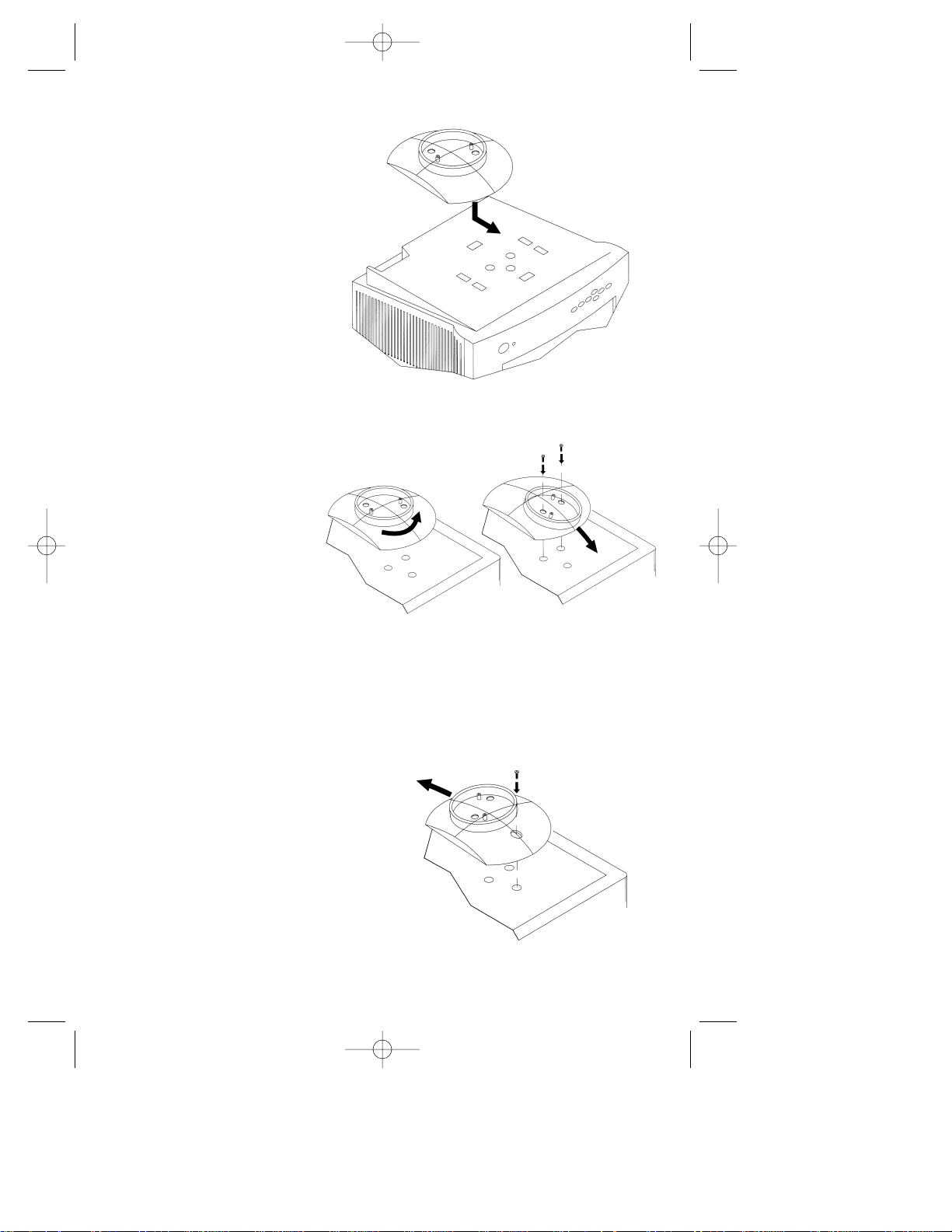
Step 5 After the adapter plate
has been attached to
the base, snap the base
assembly to the monitor.
To accomplish this, position
all the locking tabs on
the base so they mate
with the holes in the
monitor. Slide the base
assembly in place as
shown in Figure 4D.
Figure 4D
Step 6 Using two of the
screws that were
removed in Step 2,
attach the adapter
plate assembly to
the monitor. To
accomplish this, it
will be necessary
to turn the adapter
plate fully counterclockwise while sliding it
forward as shown in Figure 4E. This will allow you to install the
two rear screws.
Figure 4E
Step 7 Using the remaining screw
that was removed in Step 2,
complete attachment of the
adapter plate assembly. To
accomplish this, it will
be necessary to slide
the adapter plate backwards
as shown in Figure 4F.
Figure 4F
203 Eng Fr Cndn manual 12/21/98 11:20 AM Page 13
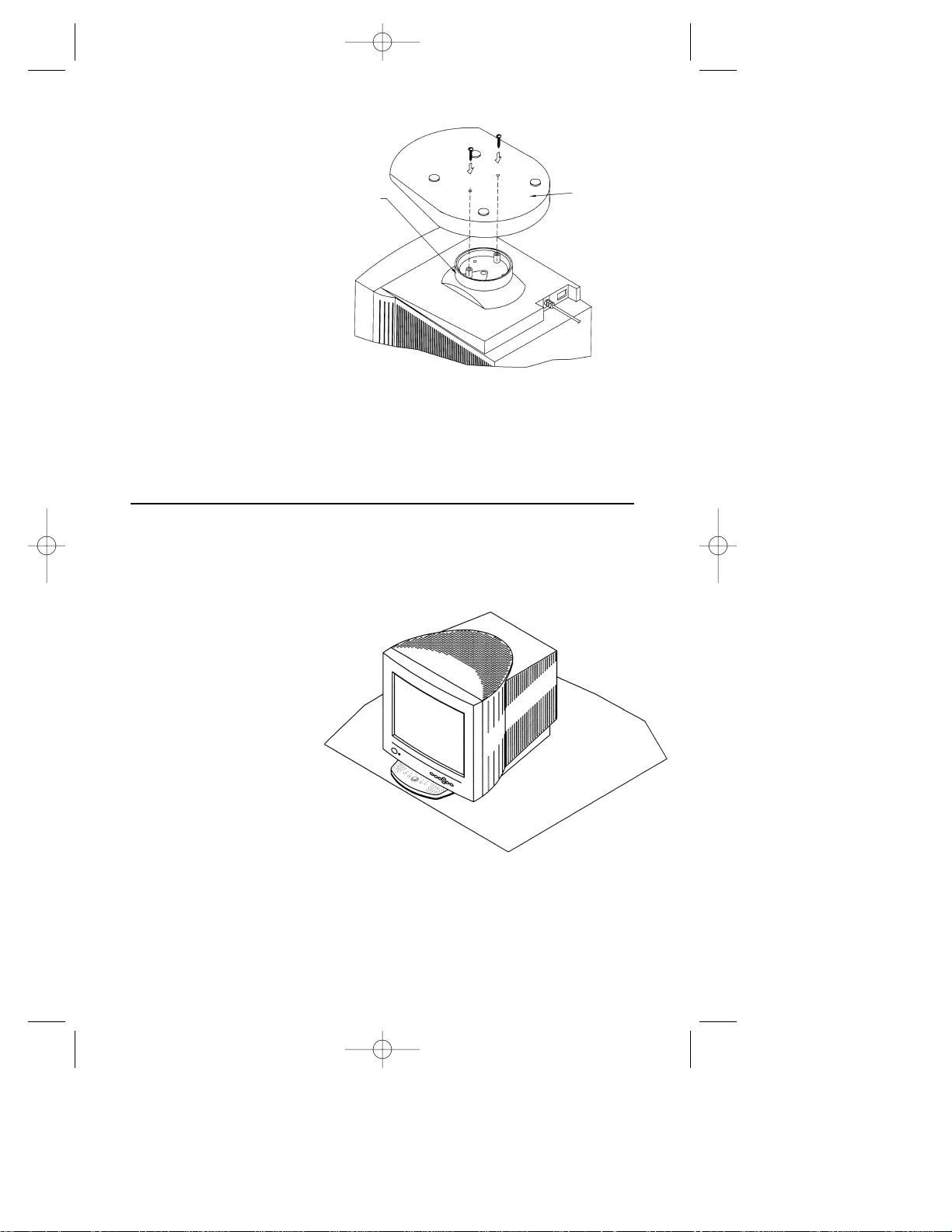
Figure 5
Step 1 Having successfully
installed your new
IntelliBase, carefully
turn the monitor
right side up
as shown in
Figure 5.
How to connect your MultiSync monitor with
IntelliBase USB Hub and Audio to your system
Figure 4G
INTELLIBASE
(BOTTOM VIEW)
ROTATE ADAPTER
PLATE UNTIL IT
ALIGNS WITH
THROUGH HOLES
ON THE BASE
203 Eng Fr Cndn manual 12/21/98 11:20 AM Page 14
Step 8 Locate the two
screws that are
supplied with
the IntelliBase
and attach the
IntelliBase to
the adapter plate
and monitor
™
as shown in
Figure 4G.
Proceed below to connect your MultiSync®monitor with the IntelliBase USB
Hub and Audio to your system.
10

Step 2 Connect one end of the supplied USB cable to the USB input jack
on the rear of the IntelliBase™(Detail B) and the other end to the
USB output jack of your computer system (Detail A) as shown in
Figure 6.
Figure 6 – REAR VIEW
Step 3 Connect one
end of the
supplied
AC adapter
to the DC
input jack
on the rear
of the
IntelliBase
and the other
end into any
110-120V
AC wall outlet as
shown in Figure 7.
NOTE: The Intellibase front green LED power indicator should be on
after this step.
Step 4 Reconnect your MultiSync®monitor to your computer system as
shown in the monitor user’s manual.
Figure 7
USB SERIES B
CONNECTOR
AUDIO
LINE
OUTPUT
SEE DETAIL A
DETAILA
DETAIL B
SEE DETAIL B
AC ADAPTER
203 Eng Fr Cndn manual 12/21/98 11:20 AM Page 15
11
203 Eng Fr Cndn manual 12/21/98 11:20 AM Page 16
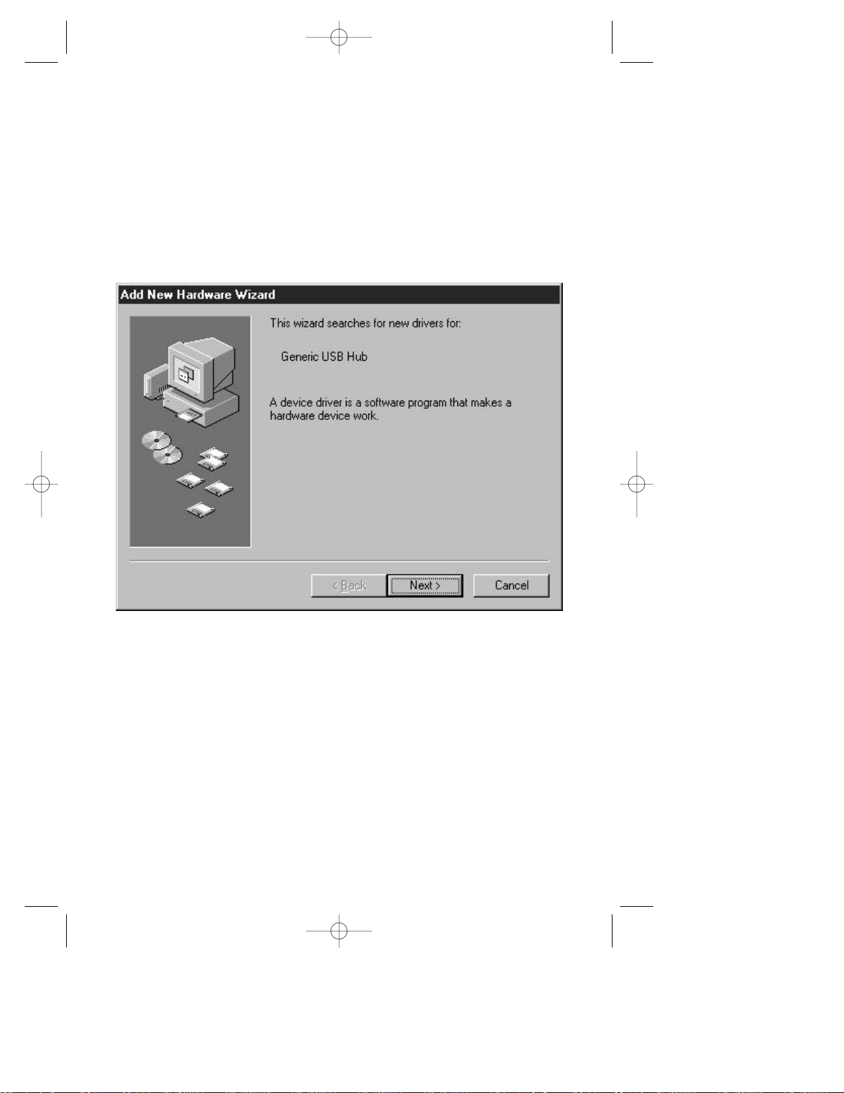
Note: Steps 5-15 describe USB driver installation for the
Windows®98 operating system. Other operating systems which
support USB may follow a different procedure.
Step 5 Turn your computer on. The computer will automatically recognize
your IntelliBase™. The Add New Hardware Wizard will
search for, locate and install the USB Controller and Hub Device
drivers needed by the IntelliBase.
Step 6 Click on Next > button to begin driver installation.
12
203 Eng Fr Cndn manual 12/21/98 11:20 AM Page 17
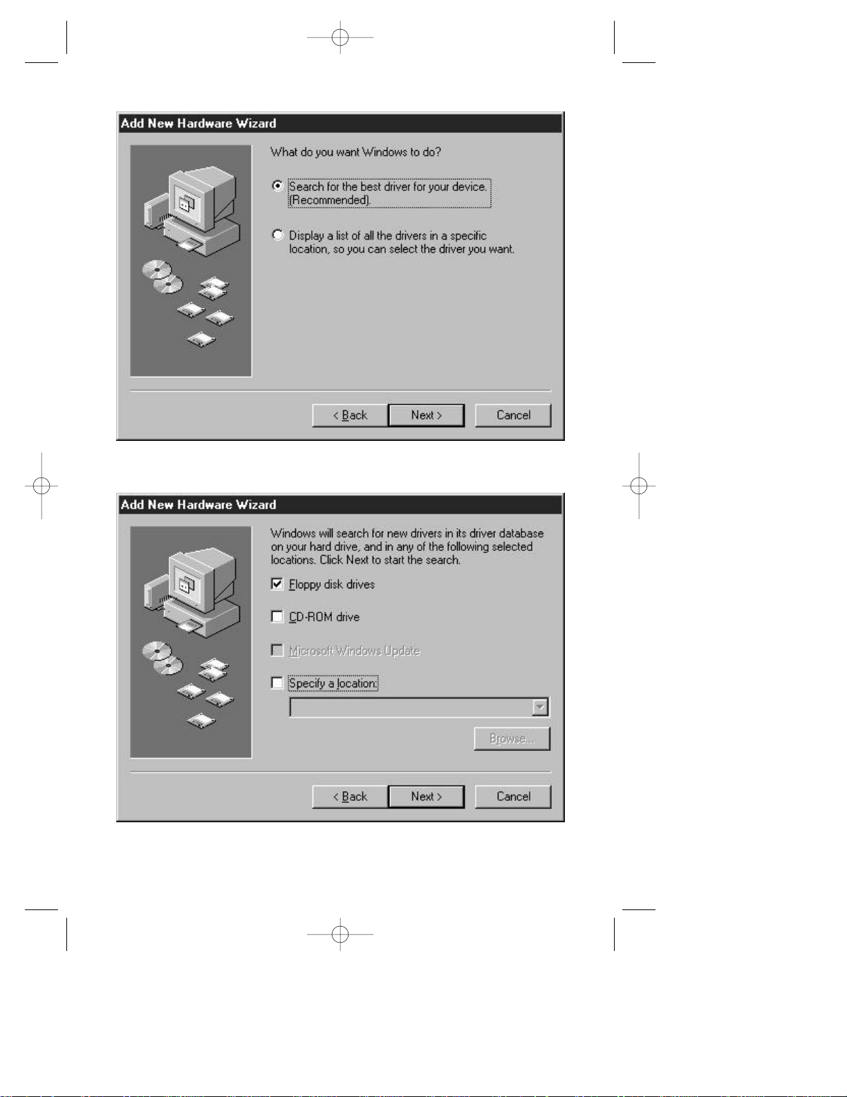
Step 7 Select Search for the best driver for your device
and then click the Next > button.
Step 8 Click Next > button to select default driver location.
13

Step 10 Insert the Windows®98 CD-ROM and then click OK. The
required files are copied from the Windows 98 CD-ROM.
Note: Depending on system configuration this message may not appear.
203 Eng Fr Cndn manual 12/21/98 11:20 AM Page 18
Step 9 Click on Next > button to install drivers. The Add New
Hardware Wizard will copy the necessary files and install
the drivers.
14
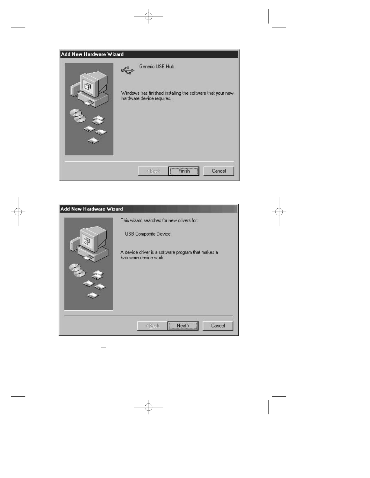
Step 11 The Hub software has been successfully loaded. Please proceed
to Step 12 to load the USB Composite Device.
Step 12 Click on Next > button to begin USB Composite Device driver
installation. Proceed to follow the screen prompts as previously
completed in Steps 5 – 11 to complete installation of the USB
Composite Device.
203 Eng Fr Cndn manual 12/21/98 11:20 AM Page 19
15
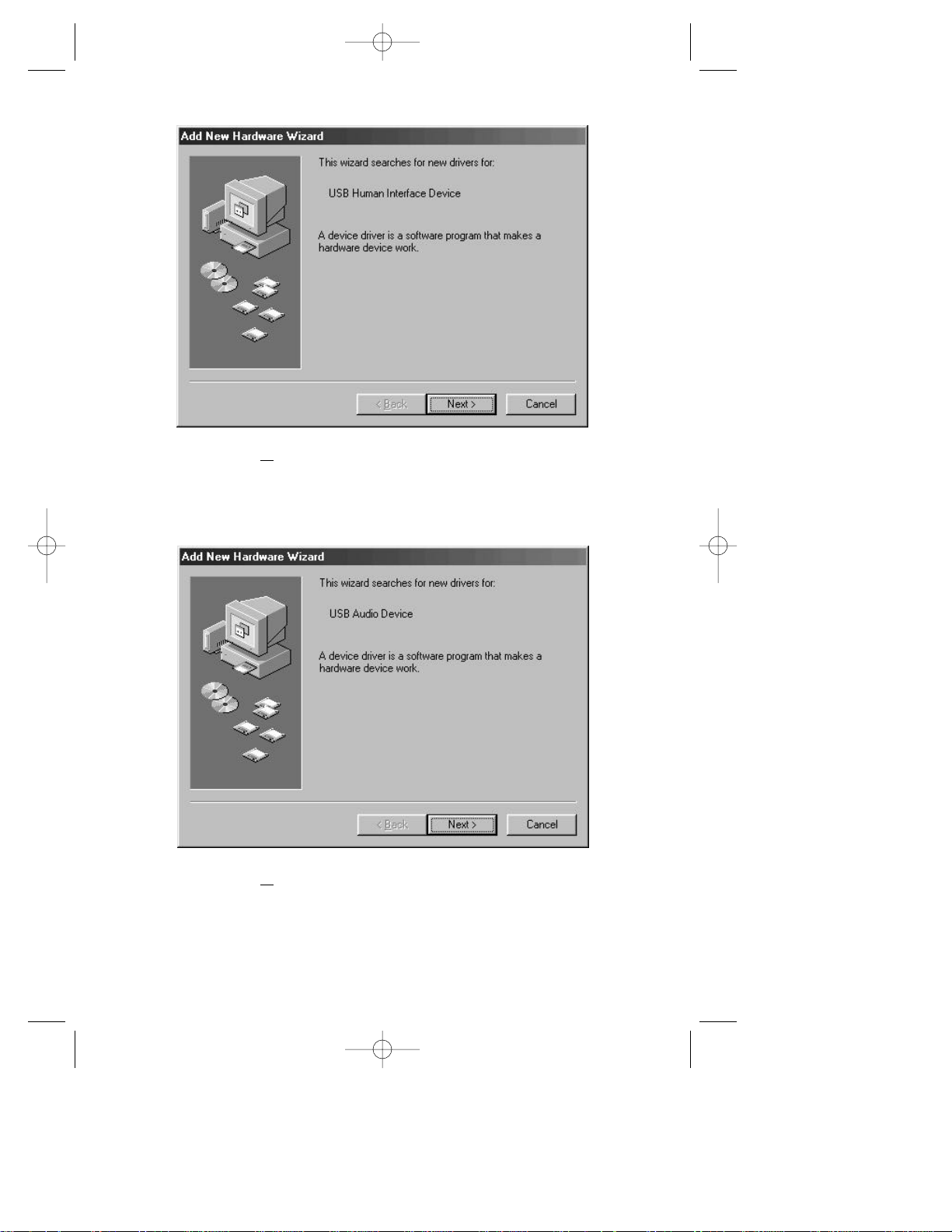
ext > button to begin USB Human Interface Device
driver installation. Proceed to follow the screen prompts as
previously completed in Steps 5 – 11 to complete installation
of the USB Human Interface Device.
Step 14 Click on Next > button to begin USB Audio Device driver
installation. Proceed to follow the screen prompts as previously
completed in Steps 5 – 11 to complete installation of the
USB Audio Device.
203 Eng Fr Cndn manual 12/21/98 11:20 AM Page 20
Step 13 Click on N
16
 Loading...