

NEC D3, D4, D3-10, D1-10 Quick Start Manual
NEC D3/D4 SAN Storage
Quick Start Guide
For the latest information, please see http://support.necam.com/Storage/D-Series/
Please feel free to contact your NEC Corporation of America approved reseller or NEC Corporation of America Technical Support at any phase of
the integration for assistance. NEC Corporation of America Technical Support can be reached by the following methods:
Web: http://support.necam.com
Email: support@necam.com
Phone: +1-877-632-0064 (toll-free)
Support contact information for other regions of the world is available at http://www.nec.com/global/support/contact/index.html
456-01812-001

Contents
Introduction ............................................................................................................................................................ 1
Understanding D-Series Array Management..................................................................................................... 2
Requirements..................................................................................................................................................... 2
STEP 1: Planning and Preparation........................................................................................................................ 3
Preparing For Installation................................................................................................................................... 3
Unpacking the Array.......................................................................................................................................... 3
Hardware Component Features........................................................................................................................4
Array Front View............................................................................................................................................. 4
Array Rear View.............................................................................................................................................. 5
STEP 2: Array Installation...................................................................................................................................... 7
Hardware Installation......................................................................................................................................... 7
Mounting the Array.......................................................................................................................................... 7
Installing Disk Drives....................................................................................................................................... 8
Cable Connections ............................................................................................................................................8
SAS Cable Connections .................................................................................................................................8
Array Connection Configurations.................................................................................................................... 9
Fibre Channel Connections............................................................................................................................ 9
Ethernet Cable Connections.........................................................................................................................10
Power Cable Connections............................................................................................................................ 11
Power-On/Power-Off Procedures....................................................................................................................11
Power-On Procedure When Auto Power On Mode Is Not Enabled............................................................. 11
Power-Off Procedure.................................................................................................................................... 12
STEP 3: Software Installation .............................................................................................................................. 13
Management Server Installation...................................................................................................................... 13
Installing Storage Manager...........................................................................................................................13
Application Server Installation.........................................................................................................................16
iSM Volume List Command Installation........................................................................................................ 17
Host Information Collection........................................................................................................................... 18
Storage Manager Client Installation ................................................................................................................ 20
Storage Manager Client Installation and Startup.......................................................................................... 20
STEP 4: Array Initialization and Configuration..................................................................................................... 22
Array Initialization ............................................................................................................................................ 22
Confirming Connections ..................................................................................................................................31
Confirming Array Connections......................................................................................................................31
Confirming Application Server Connections................................................................................................. 33
Configuring Logical Disks and Pools............................................................................................................ 35
Appendix: Configuring Multipathing..................................................................................................................... 48
Installing PathManager.................................................................................................................................... 48
Introduction
Thank you for your purchase of the NEC D3-10/D4-30 SAN Storage array. This document provides instructions
that are designed to help experienced IT professionals to install and configure the array as quickly as possible.
Since this document is a Quick Start Guide, the following assumptions have been made:
• Readers have experience with network and storage terminology and configurations.
• Readers have experience with Microsoft Windows™ administration.
• The array will be deployed in a Microsoft Windows environment.
• Expansion options, like an external battery backup unit (BBU), are not currently being installed with this
array.
Throughout this document, the term “base unit” refers to the enclosure containing the array controller modules,
and the term “array” refers to the base unit and any attached disk enclosures collectively. To read about
information not covered in this documentation, please refer to the additional documentation contained on the
CD media that comes with the array.
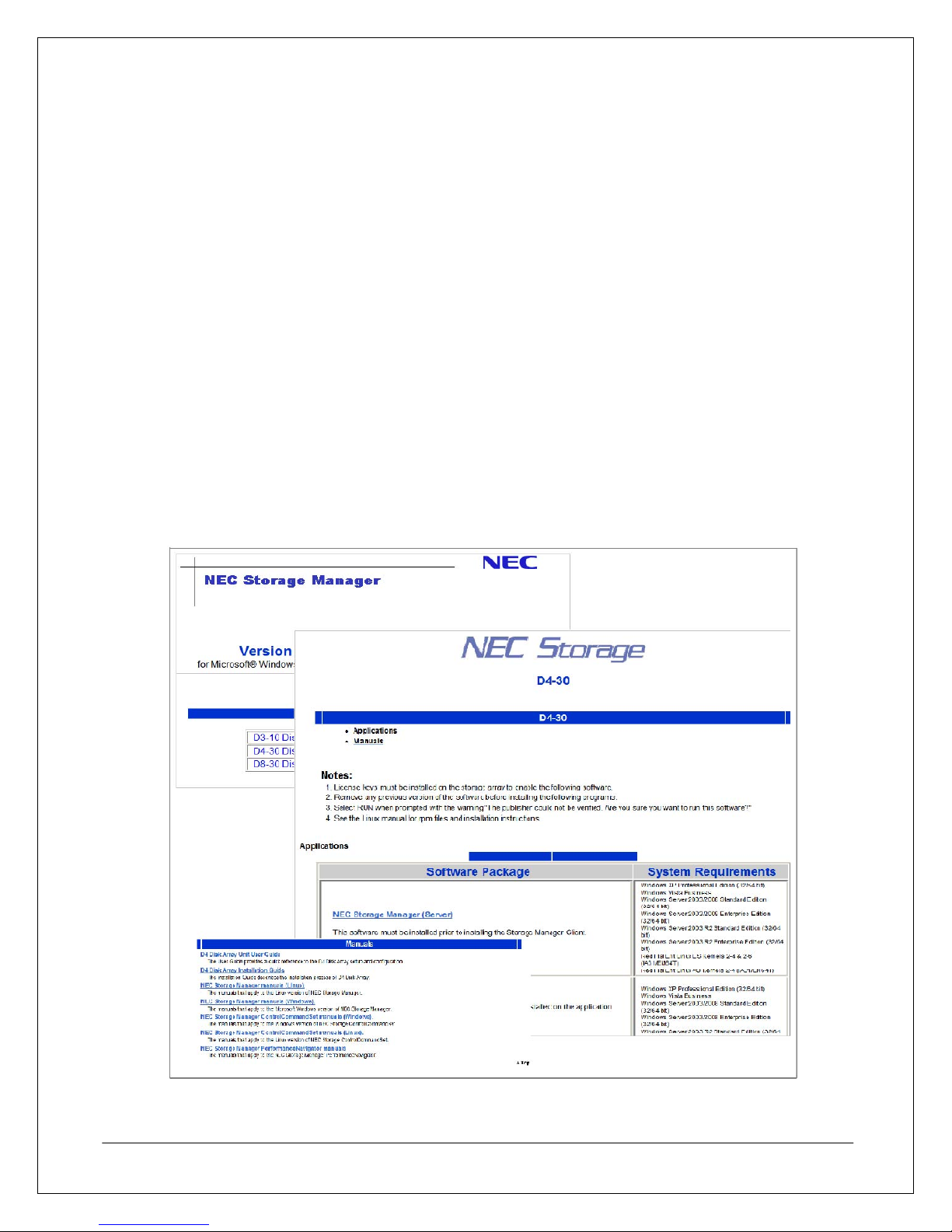
To review documentation on the Storage Manager CD when Autorun is disabled, navigate to the root directory
of the CD drive and launch Index.HTML. From the browser window, you can navigate to all the documentation
and installation software available for use with the array.
NEC D3/D4 Quick Start Guide 1
Figure 1. Storage Manager CD Navigation Windows
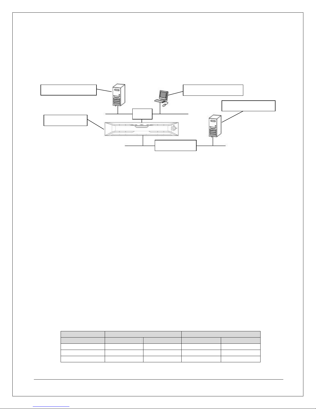
Understanding D-Series Array Management
The D-Series array is flexible enough to be implemented in a number of ways, from a single-server storage
solution up to a multi-server SAN infrastructure. No matter which approach is used, the array requires an
Ethernet connection to a server and client that will perform management functions and a Fibre Channel
connection to servers that will access the array’s storage.
Management Server Management Clients
Application Servers
LAN
D-Series Array
Fibre Channel
Figure 2. Sample D-Series Infrastructure Design
Even though these roles can be implemented on a single server, this document describes these as distinct
server roles as follows:
• Management Server – The management server role is performed by a server with the Storage
Manager software installed. This server is attached to the array via an Ethernet connection.
• Management Client – The management client role is performed by any Windows workstation or server
that connects to the management server via the Web-based management interface.
• Application Server – The application server role is performed by any server that uses the array
storage via a Fibre Channel connection.
Requirements
The following equipment, tools, and resources are required to complete this installation.
• Network Cables – At least one Ethernet cable will be required to connect the array to an Ethernet
switch or hub that is used by the server designated to manage the array. However, it is highly
recommended to use two Ethernet cables for redundancy. If the management server will be connected
directly to the array, at least one crossover Ethernet cable will be required instead.
• IP Addresses – There is a management port on each controller. Each management port to be used will
require a unique IP address. Those IP addresses should be re served and all associated network
settings should be confirmed before installation.
• Tools – You will need the installation CD (shipped with unit) and a #1 Phillips screwdriver.
• Rack space – If rack-mounting, 2U of rack space is required for each base unit and an additional 2U of
space is required for each additional disk enclosure.
• Power Requirements – Two available outlets providing AC 100-240V single phase 50/60Hz for a
NEMA 5-15P plug will be required for each base unit and each disk enclosure. Power and cooling
requirements are listed in the table below.
Maximum Wattage BTUs per Hour
Model SAS SATA SAS SATA
D3 Base Unit 620 W 550 W 2,117 1,878
D4 Base Unit 640 W 590 W 2,185 2,015
Disk Enclosure 430 W 370 W 1,468 1,263
NEC D3/D4 Quick Start Guide 2
Table 1. Storage unit power requirements

STEP 1: Planning and Preparation
This section describes the planning and preparation steps that need to occur before you install the array.
Preparing For Installation
Before installing the array, the following steps should be performed on the application servers that will be
connected to the array:
1. All requisite hardware and drivers should be installed on the application se rvers.
2. Record the WWPN (World Wide Port Name) of the Fibre Channel controller host bus adapters (HBA).
Note: This step is only required if application servers will be connected to the array using LUN masking
or soft zoning. While the WWPN is normally obtained automatically during software installation, it is still
recommended that the WWPN be recorded in case of an HBA fault or in case the software cannot
determine the WWPN and requires manual input instead.
Unpacking the Array
While unpacking instructions are illustrated on the array packaging materials, the following tips should be kept
in mind when unpacking the base unit.
• To prevent component damage caused by condensation due to rapid temperature and humidity
changes, please allow the base unit to sufficiently acclimate to the ambient room temperature before
unpacking.
• To prevent injury, the array should be unpacked, lifted out of the packing materials, and moved by at
least two people.
• To prevent damage to the base unit, the unit should be held by the bottom of the unit when removed
from the packing material or moved. It is not recommended to lift or carry the unit by holding on to
projecting surfaces such as the power supply units or plastic bezel mounts.
• Please save all packing materials in case the unit needs to be returned for repairs or shipped to other
locations.
NEC D3/D4 Quick Start Guide 3
A
y
Hardware Component Features
This section describes and illustrates a few of important components that are accessible from the front and rear
of the base unit.
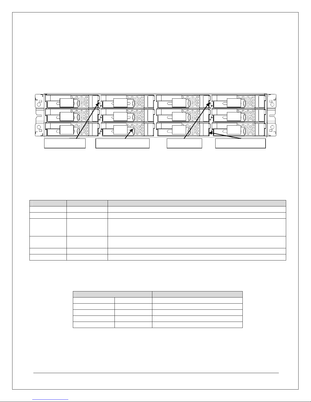
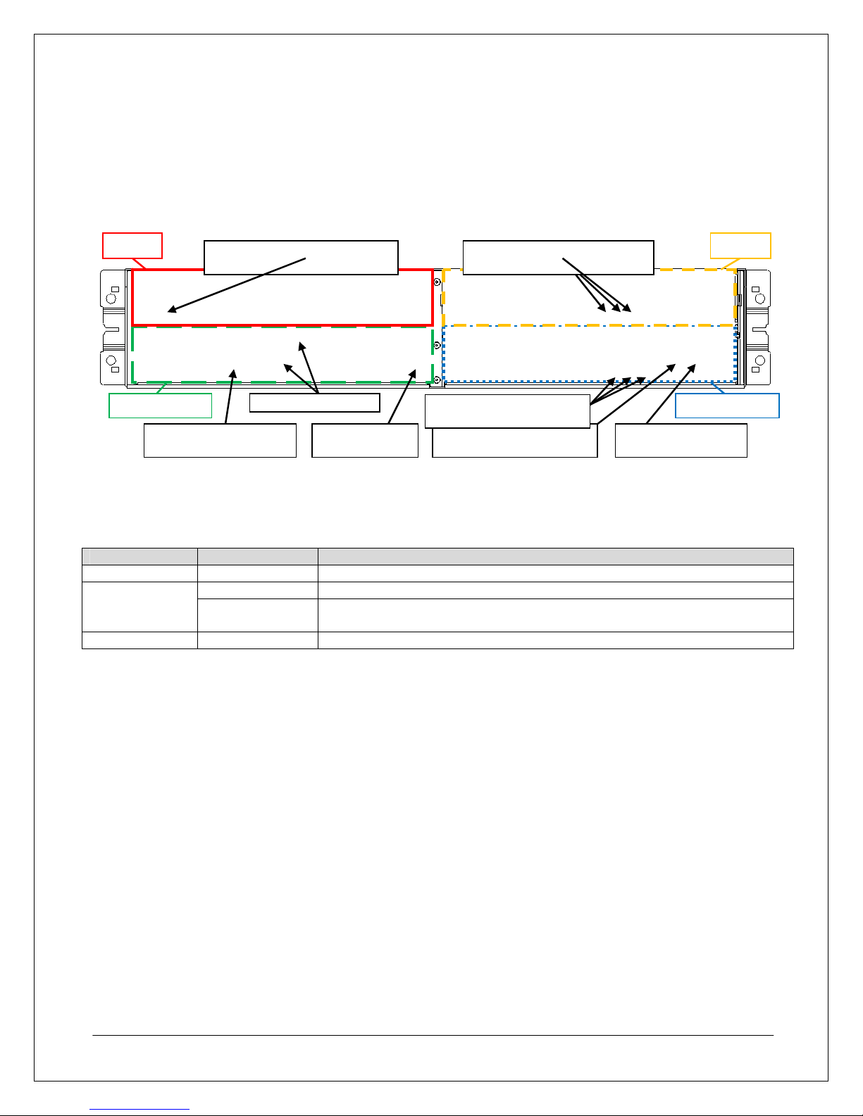
Array Front View
This section describes the array components accessible from the front.
00 02 03
04
08
Service LED Power LED
01
05
Figure 3. Array Front View (with bezel removed)
06
0A 09
07
0B
ctivity/Fault LEDDisk Drive or Tra
Disk Drives and Dummy Trays
Base units and disk enclosures have 12 disk drive slots. To maintain proper airflow and thermal conditions,
each slot is filled with either a disk drive or dummy tray.
Figure 3, above, shows the drive numbering sequence for the slots.
Service LED and Power LED
The Service and Power indicators illuminate to indicate different operating conditions as follows.
Power LED Service LED Description
ON OFF Normal operating condition
ON ON Indicates that a maintenance request or maintenance task is in process
Depending on controller LED status (which is located at the rear of the unit),
ON Blinking
this can indicate that a power-on sequence, online download sequence, or
automatic download sequence is in progress
ON
ON 5 Seconds
OFF 7 Seconds
Indicates that a condition may exist that requires immediate technical
support from NEC
Blinking OFF Cache flushed, okay to power down if desired
OFF OFF Powered off
Table 2. Power LED and Service LED Status Conditions
Active/Fault LEDs
There is a single Active/Fault LED for each disk drive slot. These indicators use different color/blinking
indicators to signal different operating conditions for each respective drive as follows:
Active/Fault LED Status
Green Steady ON Normal status (Ready)
Green Blinking Normal status (Accessing)
Green/Orange Alternating Performing RAID rebuild
Orange Blinking HDD low power condition
Orange Steady ON Abnormal status
NEC D3/D4 Quick Start Guide 4
Table 2. Active/Fault LED Status Conditions
Controlle
Controller 0
Array Rear View
The rear of the base unit provides access to the base unit’s two power supply modules (PS 0 and PS 1) and
two controller modules (Controller 0 and Controller 1), as seen in Figure 4 below.
SAS Ports and LEDs Power Button Management LAN Port Maintenance Port
Power Supply Cable Clamp Power Supply Status LEDs
r 1
FC Host Ports
Figure 4. Base Unit Rear View
Controller Status LEDs
PS 0PS 1
Power Supply Status LEDs
There are three status LEDs on each power supply that include, from left to right, a power-on LED, a power
fault LED, and a fan fault LED, which indicate the status for each power supply module as follows.
LED Indication Description
Power On LED Solid Green When lit, indicates that the power supply is on
Power Fault
LED
Solid Orange Indicates that a fault condition exists in the power supply itself
Blinking Orange
Indicates that there is an abnormal thermal condition in the power supply
or that the other power supply bay is empty
Fan Fault LED Solid Orange When lit, indicates that a fault condition exists in the power supply’s fan
Table 4. Power Supply LED Status Conditions
Controller SAS Port
The SAS ports are used to connect the base unit to additional disk enclosures and have two Status LEDs, a
green Link LED on the left and an Orange Fault LED on the right.
Fibre Channel Host Ports
The ports labeled HP and HPE on the base unit controllers are Fibre Channel Host Ports (FC Ports) that
are used to connect the array to the application servers. There are two FC Ports standard on each
controller. The number of FC ports can be expanded to four or six ports per controller on D3 b ase units with
Host Port Expansion (HPE) options.
Management and Maintenance Ports
The management port provides the network connection for the management server. The maintenance port
is only for use by NEC-authorized service professionals.
NEC D3/D4 Quick Start Guide 5
Controller Status LEDs
There are three status LEDs on each controller that include, from left to right, a Backup LED, a Fault LED,
and a Ready LED. The Backup LED will only blink to indicate that the battery backup is currently powering
the unit. The Ready and Fault LEDs use the following signal combinations to indicate controller status.
Ready LED Fault LED Status
Blinking OFF
Normal operating condition
ON OFF Startup sequence in progress
Rapid Blinking OFF Shutdown sequence in progress
Asynchronous Blinking Online/automatic download sequence in prog ress
Synchronized Blinking In download mode
ON ON Fault condition exists
ON Blinking Waiting for disk enclosure power-on
Blinking ON Disk interface is disabled
OFF OFF Powered off
Table 5. Controller Ready LED and Fault LED Status Conditions
NEC D3/D4 Quick Start Guide 6
STEP 2: Array Installation
g
This section describes the steps nece ssary to complete the physical installation of the array. These steps
should occur before you connect the array to a server.
Hardware Installation
This section describes the steps you need to perform to physically install an array into a rack and prepare for
connection to any servers.
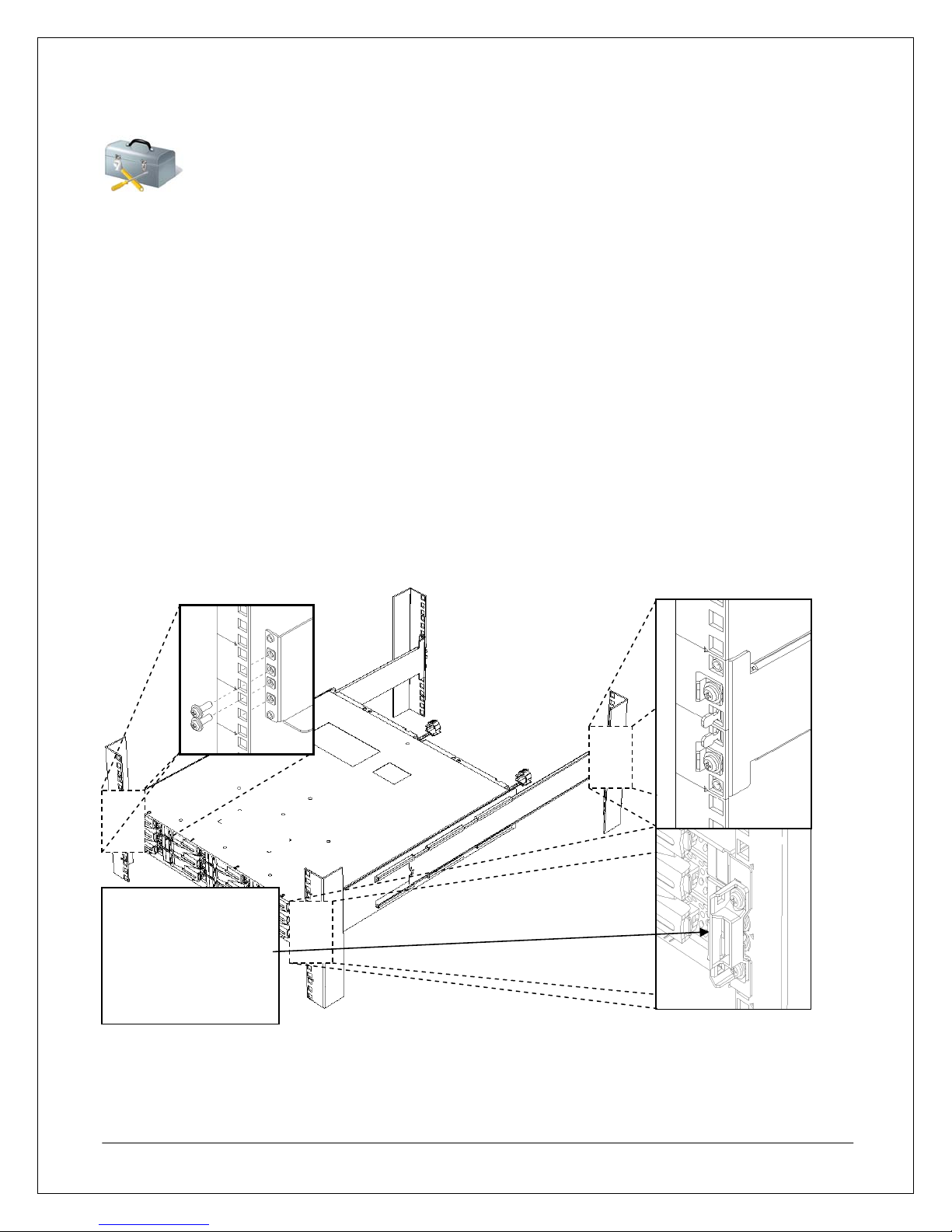
Mounting the Array
Before mounting the array in a rack enclosure, please observe the following:
• When installing both disk enclosures and base units in the same rack, the disk enclosures should be
mounted above the base unit.
• If an optional external battery backup unit (BBU) will be installed in the same rack, at least 1U of space
should be reserved underneath the base unit for the external BBU.
• If the array is being installed into a rack containing other equipment, the heaviest rack units should be
mounted as close to the bottom as possible, while lighter units can be placed near the top.
• For the purpose of determining the proper positioning in the rack, a fully loaded base unit may weigh in
excess of 68 lbs and a fully configured disk enclosure may weigh in excess of 63 lbs.
Warning: Bezel
mounts are fragile
and should not be
used as handles to lift
the base unit or be
exposed to any other
forces.
stron
The rack mount rail mounting points are illustrated in Figure 5 above and show M5 screw placeme nts for the
two center screw holes in the front of each rail. Screws are positioned above and below the inner rail tabs at the
rear of each rail as well. The array then slides into the rails from the front and is secured by two screws on each
side of the plastic bezel mount, above and below the front rail mounting screws.
NEC D3/D4 Quick Start Guide 7
Figure 5. Mounting the Array
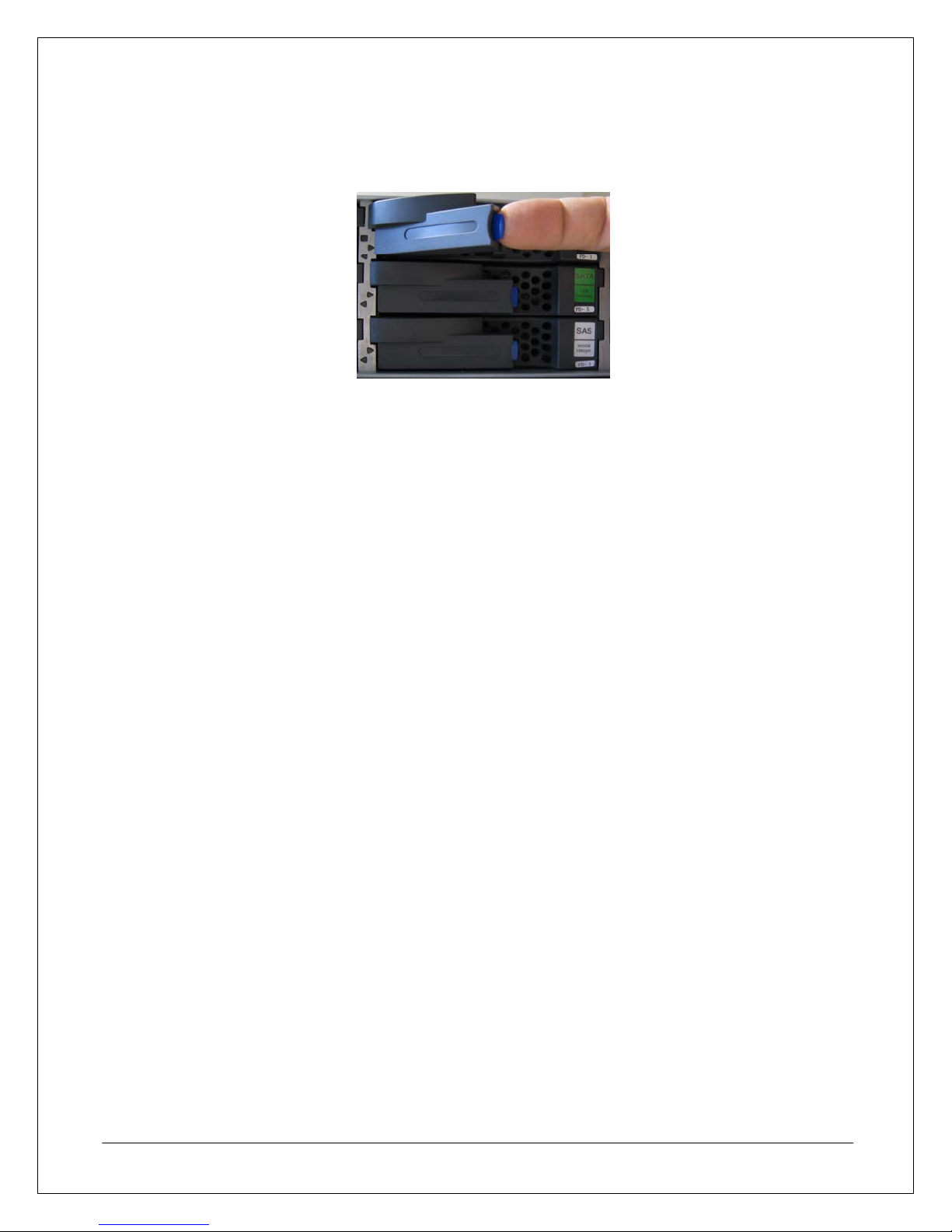
Installing Disk Drives
To remove drives or trays, simply push in the tab on the drive carrier to unlock the drive latch, pull the latch out
to the open position as seen in Figure 6 below, and then slide the drive or tray out of the disk drive bay.
Figure 6. Array Disk Drive Latch Open Position
To install a drive or tray in an empty drive bay, simply slide the drive or tray into the empty bay with the drive
latch in the open position until the drive latch catches on the inside edge of the drive bay, then move the latch to
the closed position until it locks into place with a click.
While the drive removal and insertion process is simple, there are some general guidelines to keep in mind
when installing and removing disk drives from the array.
Note: All array disk drives should be reseated before the initial startup anytime after the array is transported or
shipped with the drives installed.
• The disk drives in positions 00, 01, and 02 function as a system drive stripe set and must remain
mounted and remain in their original positions for proper array operation.
• If disk drives in positions 00, 01, or 02 must be replaced, only remove one drive at any given time.
• When installing more than one drive while the system is powered on, only install one drive at a time.
Wait until each drive reaches a ready state before installing the next drive.
• When replacing failed disk drives, replace each drive with the same drive model.
• Use dummy trays in any vacant slots to maintain proper unit air flow.
Cable Connections
This section describes the various connection points used for network, storage, and Fibre Channel connectivity.
SAS Cable Connections
The array SAS ports are used to connect the base unit with additional disk enclosures to expand storage
capacity. When connecting a disk enclosure to the base unit, use an SAS wide-link cable to connect each DPIN port on the disk enclosure to the DP0 or DP1 port on the base unit. To connect more than one disk
enclosure, connect the DP-IN on the next disk enclosure to DP-OUT on a previously connected disk encl osure
as shown in Figure 7 below.
NEC D3/D4 Quick Start Guide 8
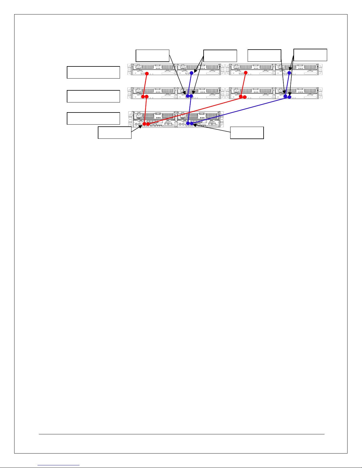
DP-OUT
DP-IN
DP-OUT
DP-IN
Disk Enclosure
Disk Enclosure
Base Unit
DP1
Figure 7. SAS Cable Connections
DP0
The D3/D4 can support up to 11 additional disk enclosures. For more information on connecti ng multiple disk
enclosures to an array, Disk Enclosure (DE) and Physical Disk (PD) numbering recommenda t ions, and other
considerations, please refer to the documentation contained in the CD shipped with your base unit.
Array Connection Configurations
The D3/D4 SAN Storage array can be used in a number of configurations ranging from a Direct Attached
Storage (DAS) configuration to being part of a SAN configuration with the array attached to a Fibre Channel
(FC) switch fabric.
• A server can be connected to the array directly via FC Point-to-Point (FC-P2P) or FC Arbitrated Loop
(FC-AL).
• Servers can be connected to the array through a switch in an FC switched fabric (FC-SW)
configuration.
• Either 1 or 2 ports per controller can be connected to hosts. With D3 and HPE option, from 4 to 6 ports
can be attached to hosts per controller.
Additionally, the array can be used in a LUN masking, multipathing, or zoning switch fabric configuration. While
zoning is configured on an FC switch and not covered here*, LUN masking and multipathing are dependent on
software installed in the array and application server.
• LUN Masking – This is the simplest method for configuring an array to connect with multiple
application servers through a switch fabric and is managed on the array through the use of Access
Control in the Storage Manager software on the management server. While it allows multiple
application servers to access array resources, it does not offer any fault tolerance unless used with
multipathing.
• Multipathing – This configuration requires use of PathManager software and some additional
configuration, but offers redundant connection paths, support for clustered servers, and other traffic
management features that aren’t available when using the array in a LUN Masking configuration by
itself. The installation and configuration of PathManager is covered in the Appendix of this guide.
*Note: For more information on zoning configurations, please refer to the manufacturer’s documentation for
your specific model FC switch.
Fibre Channel Connections
As described in the previous section, there are a number of ways in which you can connect the array to an
application server or multiple application servers. Generally, though, there are some common basic guidelines
and suggestions that should be followed when connecting the array to a server, FC hub, or FC switch.
• The array uses LC-LC-type FC cables that must be purchased separately.
NEC D3/D4 Quick Start Guide 9
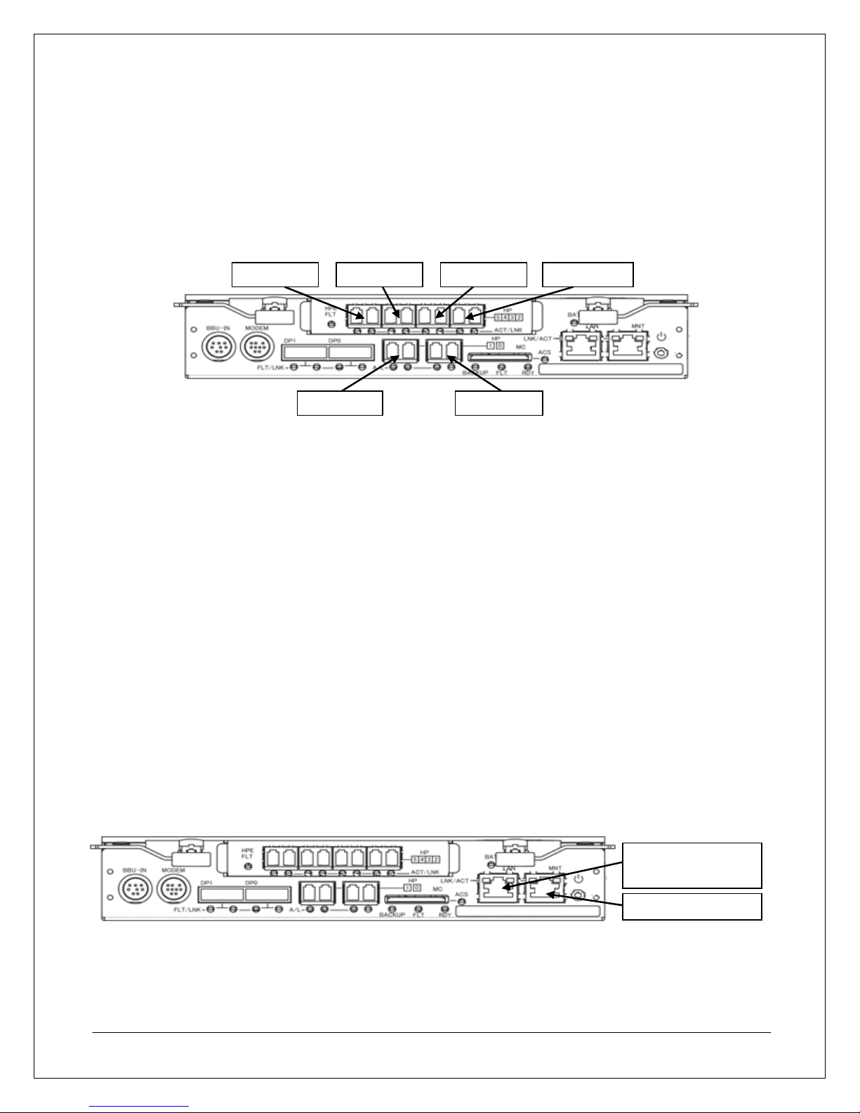
• When handling FC cables, do not touch the polished cable terminations and do not use excessive force
3
0
when connecting the cables to avoid damaging the cables or FC ports.
• Ensure that the cable paths do not expose fibre cables to excessive bending or pinching, as some fibre
cables may be susceptible to damage when bending.
• Do not dispose of the FC port covers on the array controllers, as these keep dust and other
contaminates off of the FC port lens to ensure proper FC performance. Whenever cables are not
connected to a port, the port should have a port cover in place.
FC Port 4FC Port 5
FC Port 2 FC Port
FC Port 1
Figure 8. Controller FC Ports
FC Port
As Figure 8 above shows, each array controller has two FC Host Ports (FC ports) built in and has the capacity
for additional FC ports with optional Host Port Expansion (HPE) modules. FC ports are numbered from right to
left starting at FC port 0 at the bottom right to FC port 5 at the top left where an expansion module has been
installed.
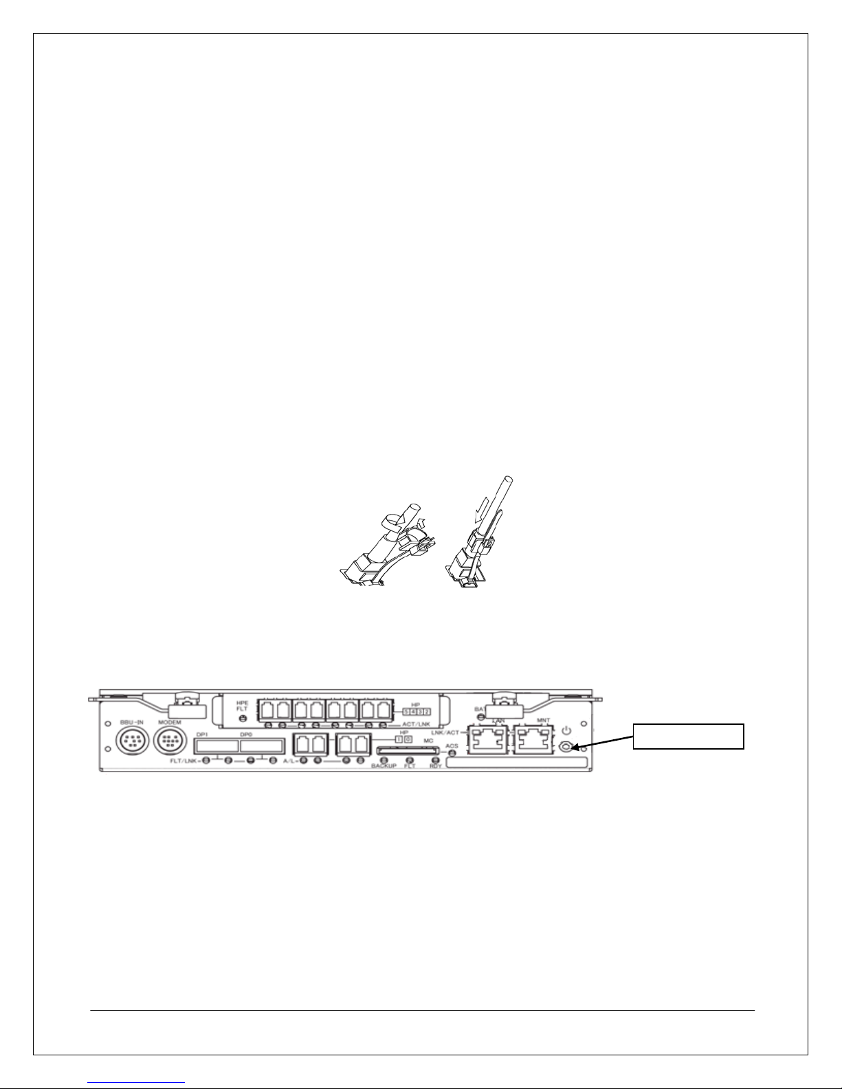
Ethernet Cable Connections
The following guidelines should be followed when connecting an array to the network.
• The array must be connected to a management server where the Storage Manager software will be
installed to configure the array.
• Use the management port on Controller 0 (the controller on the right when viewed from the back of the
unit) if only one Ethernet connection will be used for the array.
• Each management port (one on controller 0 and one on controller 1) should have its own IP a ddress
reserved on any DHCP servers. The IP address for each controller is configured manually on the array
during the initialization process outlined in the Array Initialization and Configuration section of this
guide.
• The array, Management Server, and client must be connected to the network before you use the
initialization wizard in Storage Manager to configure an array’s initial settings.
• The Management ports on both controllers should be connected to a network switch to provide the
management server with a redundant connection to the array. However, the array can be managed by
connecting just one controller to the network or directly to the management server with a crossover
cable if necessary.
NEC D3/D4 Quick Start Guide 10
Ethernet
Management Port
Maintenance Port
Figure 9. Array Controller Management Port
Power Cable Connections
The base unit is shipped in “Auto Power On” mode, so the base unit will turn on when the power cables are
plugged into the unit and an outlet. Therefore, the following steps should be followed before connecting any
power cables to the array:
• Ensure that all disk drives are properly seated.
• Ensure that all Ethernet and Fibre Channel cables have been properly connected.
• Ensure that any SAS cable connections to additional disk enclosures are properly connected.
• Plug in the power cables for any additional disk enclosures attached to the base unit before connecting
the base unit power cables.
To plug an AC power cable into a base unit or disk enclosure:
1. Spread the AC cable clamp.
2. Connect the power cable to the unit.
3. Loosely lock the clamp around the power cord, but do not tighten.
4. Move the clamp in the direction indicated in Figure 10 below until the clamp is fixed securely to the
base of the AC cable plug as shown, and then tighten.
Figure 10. Using Power Cable Management Straps
Power-On/Power-Off Procedures
The array power buttons are located on each controller module at the back of the base unit, as shown in Figure
11 below.
Power Button
Figure 11. Power Button Location on Array Controller
Power-On Procedure When Auto Power On Mode Is Not Enabled
If the array has been shut down using the power button or if Auto Power On mode is not enabled, the array can
be turned on by depressing the power button and holding it in for approximately one second. If there are two
controllers on the base unit, only one power button needs to be depressed to turn an array on or off.
When the array is first powered on, it will perform a self-test as indicated by a flashing Service LED. After the
array has successfully finished the self-test process, the Power LED should remain lit and the Service LED
should turn off. Application servers can be connected to the array after the self-test is completed.
NEC D3/D4 Quick Start Guide 11

*Note: If the Power LED does not remain lit or if the Service LED does not turn off after the self-test a controller
fault may have occurred. For information about identifying and troubleshooting fault conditions, please refer to
the D3/D4 Disk Array Unit User Guide available on the Storage Manager CD or contact NEC techni cal support.
Power-Off Procedure
To prevent any data loss or corruption, the following process should be followed when an array is to be shu t
down.
1. Turn off or disconnect application servers using the prescribed shut-down process for that server’s
applications and operating system.
2. Turn off the array by depressing the power button until the Ready LED starts blinks at a faster rate then
release the power button. The power button is located on the array controller at the rear of the base
unit.
3. Turn off the external BBU if used.
4. If the array needs to remain powered off for more than a few hours, partially eject both controllers from
the base unit at the same time and then reseat them, to prevent the internal battery backup from
draining.
NEC D3/D4 Quick Start Guide 12
STEP 3: Software Installation
The D3/D4 SAN Storage array comes standard with Storage Manager software that is required to use basic
array features. To extend an array’s feature sets, additional software can be installed depending on which
features would be best suited for any given environment.
This guide covers the installation and configuration tasks that would be necessary to enable the com mon
functionality required in an average enterprise environment using Storage Manager software. For more
information about other software suites and the features they enable for the D-Series array, please refer to the
relevant documentation on the CD included with the base unit.
Management Server Installation
The Storage Manager setup CD contains installation software for systems perfo rming the management server,
application server, and management client roles.
The Storage Manager software generates a large number of files and constantly updates files during norm al
operation. Therefore, it is recommended that the installation path for the Storage Manager software be
excluded from any real-time virus scanning routine. Also, while a single management server can monitor
several arrays simultaneously, an array should not be managed by more than one management server.
Installing Storage Manager
The following steps take place on the system designated as the ma nagement server.
1. Log in to the management server using an account with administrator privileges.
2. Insert the Storage Manager CD.
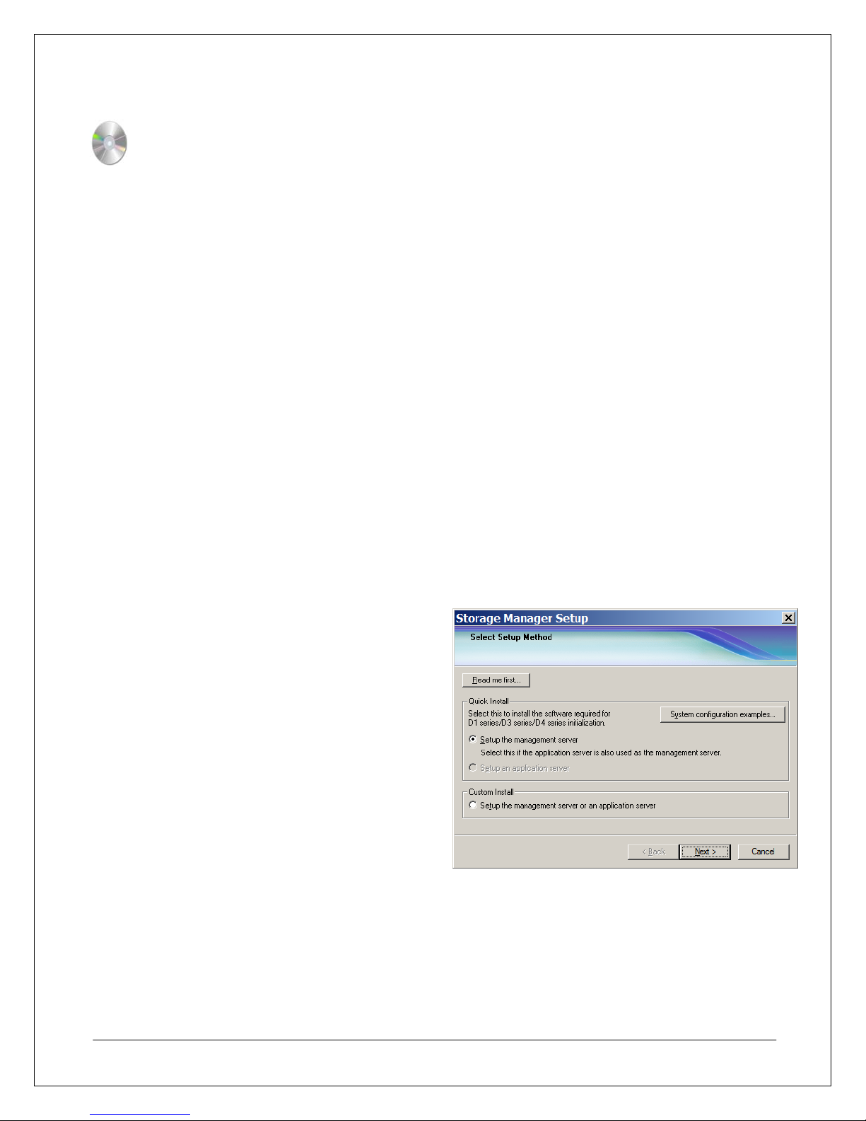
3. Start the Storage Manager setup. If the Storage Manager setup does not start automatically after
inserting the CD, manually run <CD Drive>:\StorageManager\Install\Windows\ISMSETUP.EXE
4. At the Select Setup Method window, select
Setup the management server from the
Quick Install section, and then click Next.
*Note: Windows Server 2008 in UAC mode
may require an additional step before this step
to grant permission to run the setup.
NEC D3/D4 Quick Start Guide 13
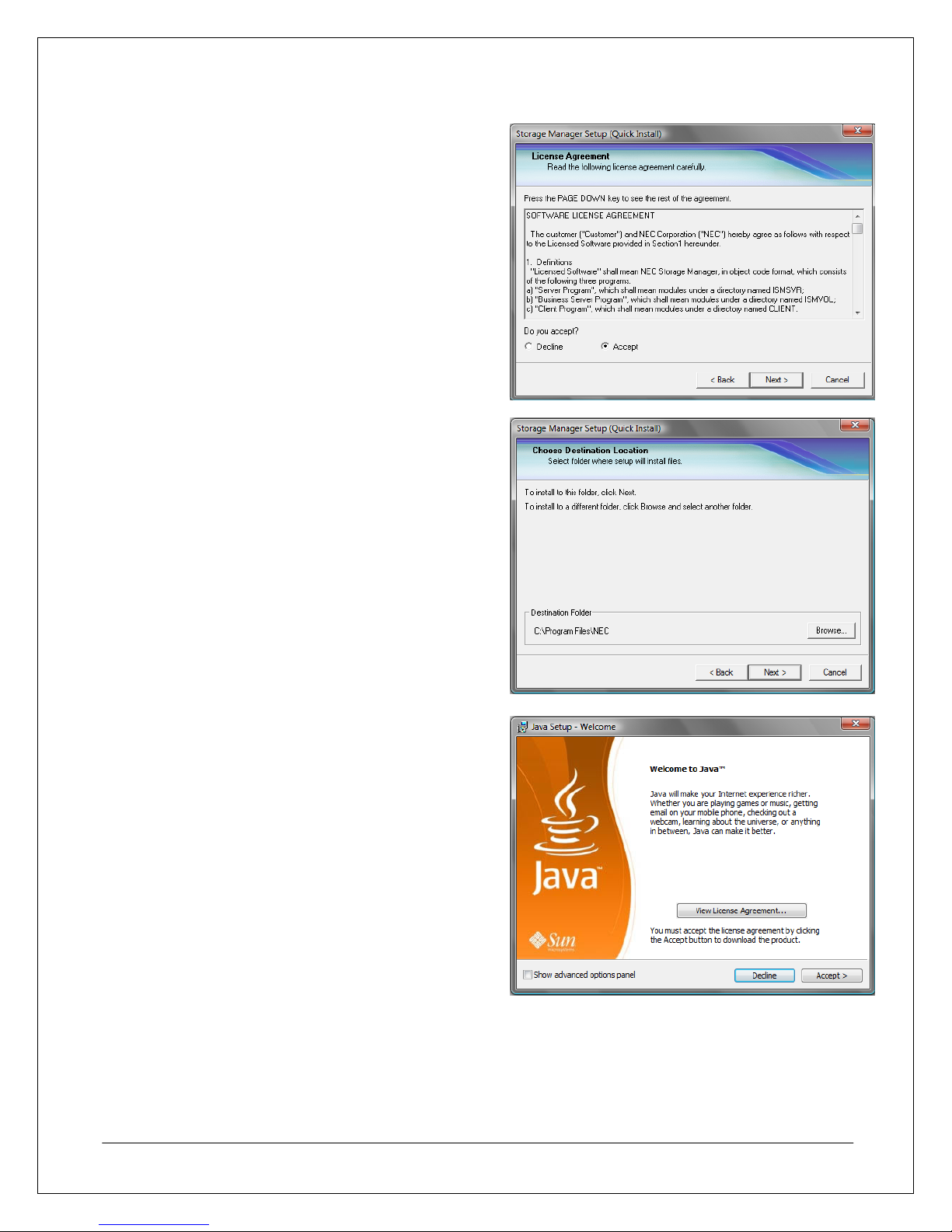
5. At the License Agreement window, select
Accept, and then click Next.
6. At the Choose Destination Location window,
either leave the default installation path in place
or click Browse to select a new installation path,
and then click Next.
7. At this point, the Storage Manager installation
will attempt to install Java. Click Accept to begin
installing Java.
Note: Storage Manager requires the use of a
specific version of Java that comes with the
installation software. Ensure that Java is installed
during this step even if another version of Java
has already been installed on this server to avoid
any compatibility issues.
NEC D3/D4 Quick Start Guide 14
 Loading...