

Page 1

®
ND-45669 (E)
ISSUE 2
PART OF STOCK # 151901
Command Manual
DECEMBER, 1997
NEC America, Inc.
Page 2

LIABILITY DISCLAIMER
NEC America, Inc. reserves the right to change the specifications,
functions, or features, at any time, without notice.
NEC America, Inc. has prepared this docum ent for use by its em ployees and customers. The information contained herein is the
property of NEC America, Inc. and shall not be reproduced without
prior written approval from NEC America, Inc.
NEAX and D
term
are registered trademarks of NEC Corporation.
Copyright 1997
NEC America, Inc.
Printed in U SA
Page 3

PAGE No.
i 2.2
ii
iii 2.1
iv 2.1
v
vi
1
2
3
4
5
6
7
8
9
10
11
12
13 2.1
14
15
16
17
18
19
20 2.2
21
22
23
24
25
26
27
28
29
30
31
32
ADDENDUM-001 ADDENDUM-002 ADDENDUM-003 ADDENDUM-004
DATE A UGUST, 1998 DATE JANUARY, 1999 DATE DATE
ADDENDUM-005 ADDENDUM-006 ADDENDUM-007 ADDENDUM-008
DA TE DATE DA TE DATE
001
002 003 004 005 006 007 008
ADD . No.
PAGE No.
001
33
34
35
36
37
38
39
40
41
42
43
44 2.1
44-1 2.1
44-2 2.1
45 2.2
46
47
48
49
50 2.1 2.2
51
52
53
54
55
56
57
58 2.1
59
60
61
62 2.2
63
64
65
66 2.1
67 2.1
68 2.1
002 003 004 005 006 007 008
ADD. No.
NEAX2000 IVS
Command Manual
Addendum Revision Sheet 1/7
ND-45669 (E) ISSUE 2
Page 4

PAGE No.
69
70 2.1 2.2
70-1 2.2
70-2
71
72
73
74 2.1
74-1 2.1
74-2 2.1
75
76
77 2.2
77-1 2.2
77-2 2.2
78
79 2.1
80
81
82
83 2.1
84 2.1
85
86
87
88 2.1
89
90 2.1
91
92
93
94
95
96 2.1
97
98
99
100
ADDENDUM-001 ADDENDUM-002 ADDENDUM-003 ADDENDUM-004
DATE A UGUST, 1998 DATE JANUARY, 1999 DATE DATE
ADDENDUM-005 ADDENDUM-006 ADDENDUM-007 ADDENDUM-008
DA TE DATE DA TE DATE
001
002 003 004 005 006 007 008
2.2
2.2
ADD . No.
PAGE N o.
001
101 2.2
102
103
104
105 2.1
106 2.1
107
108
109
110 2.1 2.2
110-1 2.1 2.2
110-2 2.1
111
112
113
114
115
116
117
118
119
120
121 2.1
122
123
124
125
126 2.2
127
128 2.1
129 2.1
130 2.2
131
132
133
134
135
136
002 003 004 005 006 007 008
2.2
ADD. No.
NEAX2000 IVS
Command Manual
Addendum Revision Sheet 2/7
ND-45669 (E) ISSUE 2
Page 5

PAGE No.
137
138
139
140 2.1 2.2
140-1 2.1 2.2
140-2 2.1
141
142
143
144
145
146
147
148
149
150
151
152
153 2.1
154
155 2.1
156 2.2
156-1 2.2
156-2
157
158
159
160 2.1 2.2
161
162
163
164
165
166
167
168
169
170
ADDENDUM-001 ADDENDUM-002 ADDENDUM-003 ADDENDUM-004
DATE A UGUST, 1998 DATE JANUARY, 1999 DATE DATE
ADDENDUM-005 ADDENDUM-006 ADDENDUM-007 ADDENDUM-008
DA TE DATE DA TE DATE
001
002 003 004 005 006 007 008
2.2
ADD . No.
PAGE N o.
001
171
172 2.1
173 2.1
174 2.1
174-1 2.1
174-2 2.1
175
176
177
178
179
180
181
182
183
184 2.2
185
186
187
188
188-1 2.1
188-2 2.1
189
190
191 2.1
192
193 2.1
194
195
196
197
198
199 2.1
199-1 2.1
199-2 2.1
200 2.1 2.2
201
202
002 003 004 005 006 007 008
ADD. No.
NEAX2000 IVS
Command Manual
Addendum Revision Sheet 3/7
ND-45669 (E) ISSUE 2
Page 6

PAGE No.
203 2.2
204
205 2.1
206 2.2
207 2.2
208
209
210 2.2
211
212
213 2.2
214
215 2.1
216 2.1 2.2
216-1 2.1
216-2 2.1
217 2.1
218 2.1
219
220
221 2.1
222
223
224
225
226
227
228
229
230
231
232
233 2.2
234 2.2
235
236 2.1
237 2.1 2.2
238
ADDENDUM-001 ADDENDUM-002 ADDENDUM-003 ADDENDUM-004
DATE A UGUST, 1998 DATE JANUARY, 1999 DATE DATE
ADDENDUM-005 ADDENDUM-006 ADDENDUM-007 ADDENDUM-008
DA TE DATE DA TE DATE
001
002 003 004 005 006 007 008
ADD . No.
PAGE N o.
001
239 2.1
240
241
242
243
244
245
246
247 2.2
248
249
250
251
252
253
254
255
256
257
258
259
260
261
262
263 2.1
264 2.1
265
266 2.1
267
268
269
270
271
272
273
274
275
276 2.2
002 003 004 005 006 007 008
ADD. No.
NEAX2000 IVS
Command Manual
Addendum Revision Sheet 4/7
ND-45669 (E) ISSUE 2
Page 7

PAGE No.
277 2.2
278
279
280
281
282
283
284
285
286
287 2.1 2.2
288 2.1
289 2.1
290 2.1
291
292
293
294
295
296
297
298
299
300
301
302
303
304
305
306
307
308
309
310 2.2
311 2.2
311-1
311-2 2.2
312
ADDENDUM-001 ADDENDUM-002 ADDENDUM-003 ADDENDUM-004
DATE A UGUST, 1998 DATE JANUARY, 1999 DATE DATE
ADDENDUM-005 ADDENDUM-006 ADDENDUM-007 ADDENDUM-008
DA TE DATE DA TE DATE
001
002 003 004 005 006 007 008
2.2
ADD . No.
PAGE N o.
001
313
314
315
316
317
318
319
320
321
322
323
324 2.1
325
326 2.1
327 2.1
327-1 2.1
327-2 2.1 2.2
327-3 2.1
327-4 2.1
328
329
330
331
332
333
334
335
336
337
338
339
340
341
342
343
344
345
346
002 003 004 005 006 007 008
ADD. No.
NEAX2000 IVS
Command Manual
Addendum Revision Sheet 5/7
ND-45669 (E) ISSUE 2
Page 8

PAGE No.
347
348 2.2
349 2.2
350
351
352
353 2.2
354
355
356
357
358
359
360
361
362
363
364
365
366
367
368
369
370 2.1
371 2.1
372
373
374
375
376
377
378
379
380
381
382
383
384
ADDENDUM-001 ADDENDUM-002 ADDENDUM-003 ADDENDUM-004
DATE A UGUST, 1998 DATE JANUARY, 1999 DATE DATE
ADDENDUM-005 ADDENDUM-006 ADDENDUM-007 ADDENDUM-008
DA TE DATE DA TE DATE
001
002 003 004 005 006 007 008
ADD . No.
PAGE N o.
001
385
386
387
388
389
390
391
392
393
394
395 2.1
396
397
398 2.2
399 2.2
400
401
402
403
404
405
406
407
408
409
410
411
412 2.2
413
414 2.2
415
416
417
418
419
420
421
422
002 003 004 005 006 007 008
ADD. No.
NEAX2000 IVS
Command Manual
Addendum Revision Sheet 6/7
ND-45669 (E) ISSUE 2
Page 9

PAGE No.
423
424
425
426
427
428
429
430
ADD . No.
001
002 003 004 005 006 007 008
PAGE N o.
ADD. No.
001
002 003 004 005 006 007 008
ADDENDUM-001 ADDENDUM-002 ADDENDUM-003 ADDENDUM-004
DATE A UGUST, 1998 DATE JANUARY, 1999 DATE DATE
ADDENDUM-005 ADDENDUM-006 ADDENDUM-007 ADDENDUM-008
DA TE DATE DA TE DATE
NEAX2000 IVS
Command Manual
Addendum Revision Sheet 7/7
ND-45669 (E) ISSUE 2
Page 10

ND-45669 (E)
ISSUE 2
DECEMBER, 1997
NEAX2000 IVS
Command Manual
TABLE OF CONTENTS
Page
LIST OF FIGURES . . . . . . . . . . . . . . . . . . . . . . . . . . . . . . . . . . . . . . . . . . . . . . . . . . . . . . . . . . . . . . . . . . . . . . . v
LIST OF TABLES . . . . . . . . . . . . . . . . . . . . . . . . . . . . . . . . . . . . . . . . . . . . . . . . . . . . . . . . . . . . . . . . . . . . . . . . vi
CHAPTER 1 INTRODUCTION . . . . . . . . . . . . . . . . . . . . . . . . . . . . . . . . . . . . . . . . . . . . . . . . . . . . . . . . . . . 1
1. PURPOSE . . . . . . . . . . . . . . . . . . . . . . . . . . . . . . . . . . . . . . . . . . . . . . . . . . . . . . . . . . . . . . . . . . . . . . 1
2. OUTLINE OF THE MANUAL. . . . . . . . . . . . . . . . . . . . . . . . . . . . . . . . . . . . . . . . . . . . . . . . . . . . . . . . 1
CHAPTER 2 INFORMATION FOR DATA PROGRAMMING . . . . . . . . . . . . . . . . . . . . . . . . . . . . . . . . . . . . 3
1. GENERAL . . . . . . . . . . . . . . . . . . . . . . . . . . . . . . . . . . . . . . . . . . . . . . . . . . . . . . . . . . . . . . . . . . . . . . 3
2. DESCRIPTION OF CAT AND MAT. . . . . . . . . . . . . . . . . . . . . . . . . . . . . . . . . . . . . . . . . . . . . . . . . . . 3
2.1 How to Use the CAT. . . . . . . . . . . . . . . . . . . . . . . . . . . . . . . . . . . . . . . . . . . . . . . . . . . . . . . . . . 3
2.1.1 CAT Key Functions . . . . . . . . . . . . . . . . . . . . . . . . . . . . . . . . . . . . . . . . . . . . . . . . . . . . 3
2.1.2 CA T Mode S etting Procedure . . . . . . . . . . . . . . . . . . . . . . . . . . . . . . . . . . . . . . . . . . . . 6
2.1.3 Notice on the CAT Mode. . . . . . . . . . . . . . . . . . . . . . . . . . . . . . . . . . . . . . . . . . . . . . . . 6
2.2 CAT Operation. . . . . . . . . . . . . . . . . . . . . . . . . . . . . . . . . . . . . . . . . . . . . . . . . . . . . . . . . . . . . . 7
2.3 Error Messages . . . . . . . . . . . . . . . . . . . . . . . . . . . . . . . . . . . . . . . . . . . . . . . . . . . . . . . . . . . . . 10
3. COMMAND REFERENCE TABLE. . . . . . . . . . . . . . . . . . . . . . . . . . . . . . . . . . . . . . . . . . . . . . . . . . . . 11
3.1 List of Commands . . . . . . . . . . . . . . . . . . . . . . . . . . . . . . . . . . . . . . . . . . . . . . . . . . . . . . . . . . . 11
3.2 Quick Reference Table of Commands Required for Service Feature . . . . . . . . . . . . . . . . . . . . 14
4. PRECAUTION . . . . . . . . . . . . . . . . . . . . . . . . . . . . . . . . . . . . . . . . . . . . . . . . . . . . . . . . . . . . . . . . . . . 55
4.1 Conditions for Using Commands . . . . . . . . . . . . . . . . . . . . . . . . . . . . . . . . . . . . . . . . . . . . . . . . 55
4.2 Method of Setting On-Line/Off-Line Mo de . . . . . . . . . . . . . . . . . . . . . . . . . . . . . . . . . . . . . . . . . 56
4.3 Method for Installing Line/Trunk Cards . . . . . . . . . . . . . . . . . . . . . . . . . . . . . . . . . . . . . . . . . . . 57
4.4 Password Entry . . . . . . . . . . . . . . . . . . . . . . . . . . . . . . . . . . . . . . . . . . . . . . . . . . . . . . . . . . . . . 59
CHAPTER 3 DESCRIPTION OF COMMANDS . . . . . . . . . . . . . . . . . . . . . . . . . . . . . . . . . . . . . . . . . . . . . . 61
1. GENERAL . . . . . . . . . . . . . . . . . . . . . . . . . . . . . . . . . . . . . . . . . . . . . . . . . . . . . . . . . . . . . . . . . . . . . . 61
2. DETAILED DESCRIPTION OF COMMANDS . . . . . . . . . . . . . . . . . . . . . . . . . . . . . . . . . . . . . . . . . . . 61
[CM00] System Data Memory All Clear . . . . . . . . . . . . . . . . . . . . . . . . . . . . . . . . . . . . . . . . 62
[CM01] System Data Memory Partial Clear . . . . . . . . . . . . . . . . . . . . . . . . . . . . . . . . . . . . . 63
[CM02] Setting of System Clock. . . . . . . . . . . . . . . . . . . . . . . . . . . . . . . . . . . . . . . . . . . . . . 64
[CM03] Log In/Log Out of Password Mode . . . . . . . . . . . . . . . . . . . . . . . . . . . . . . . . . . . . . 65
[CM04] Language Indicated on Multiline Terminal LCD. . . . . . . . . . . . . . . . . . . . . . . . . . . . 66
[CM05] Card Assignment . . . . . . . . . . . . . . . . . . . . . . . . . . . . . . . . . . . . . . . . . . . . . . . . . . . 67
[CM06] Misc. Trunk Number Assignment. . . . . . . . . . . . . . . . . . . . . . . . . . . . . . . . . . . . . . . 69
[CM07] DTI Trunk/ISDN Trunk Assignment . . . . . . . . . . . . . . . . . . . . . . . . . . . . . . . . . . . . . 70
[CM08] Basic Service Features . . . . . . . . . . . . . . . . . . . . . . . . . . . . . . . . . . . . . . . . . . . . . . 71
[CM09] Additional Service Features. . . . . . . . . . . . . . . . . . . . . . . . . . . . . . . . . . . . . . . . . . . 89
[CM10] Station Number, Trunk Number, Card Number . . . . . . . . . . . . . . . . . . . . . . . . . . . . 90
[CM11] Virtual-Line Number . . . . . . . . . . . . . . . . . . . . . . . . . . . . . . . . . . . . . . . . . . . . . . . . . 96
ND-45669 (E) TABLE OF CONTENTS
Addendum-002 Page i
JANUARY, 1999 Revision 2.2
Page 11

TABLE OF CONTENTS (CONTINUED)
Page
[CM12] Station Class-1. . . . . . . . . . . . . . . . . . . . . . . . . . . . . . . . . . . . . . . . . . . . . . . . . . . . . 99
[CM13] Station Class-2. . . . . . . . . . . . . . . . . . . . . . . . . . . . . . . . . . . . . . . . . . . . . . . . . . . . . 104
[CM15] Service Restriction Class. . . . . . . . . . . . . . . . . . . . . . . . . . . . . . . . . . . . . . . . . . . . . 107
[CM16] Cal l Pickup Group/Gr oup Diversion Group . . . . . . . . . . . . . . . . . . . . . . . . . . . . . . . 114
[CM17] UCD Group . . . . . . . . . . . . . . . . . . . . . . . . . . . . . . . . . . . . . . . . . . . . . . . . . . . . . . . 116
[CM18] Station Hunting Group. . . . . . . . . . . . . . . . . . . . . . . . . . . . . . . . . . . . . . . . . . . . . . . 118
[CM19] Secretary/Group Diversion Station Number. . . . . . . . . . . . . . . . . . . . . . . . . . . . . . . 124
[CM1A] Data Station Number. . . . . . . . . . . . . . . . . . . . . . . . . . . . . . . . . . . . . . . . . . . . . . . . 125
[CM1B] ISDN Terminal Multipoints Station Number Assignment . . . . . . . . . . . . . . . . . . . . . 126
[CM1C] PS Station Number Assignment . . . . . . . . . . . . . . . . . . . . . . . . . . . . . . . . . . . . . . . 127
[CM1D] PS - ID Assi gnment/P S Oper a tion D a ta D o wnlo a d . . . . . . . . . . . . . . . . . . . . . . . . . . 128
[CM20] Numbering Plan. . . . . . . . . . . . . . . . . . . . . . . . . . . . . . . . . . . . . . . . . . . . . . . . . . . . 129
[CM21] Single Digit Access Code. . . . . . . . . . . . . . . . . . . . . . . . . . . . . . . . . . . . . . . . . . . . . 142
[CM22] Route Advance . . . . . . . . . . . . . . . . . . . . . . . . . . . . . . . . . . . . . . . . . . . . . . . . . . . . 143
[CM23] T enant Development . . . . . . . . . . . . . . . . . . . . . . . . . . . . . . . . . . . . . . . . . . . . . . . . 144
[CM24] Kind of Ca lling Termin al D e ve lopment . . . . . . . . . . . . . . . . . . . . . . . . . . . . . . . . . . . 145
[CM25] Kind of Special Terminal Development . . . . . . . . . . . . . . . . . . . . . . . . . . . . . . . . . . 146
[CM26] Closed Number Development . . . . . . . . . . . . . . . . . . . . . . . . . . . . . . . . . . . . . . . . . 147
[CM29] Num beri ng Plan Tenant Group . . . . . . . . . . . . . . . . . . . . . . . . . . . . . . . . . . . . . . . . 149
[CM2A] ID Code Assignment with MP . . . . . . . . . . . . . . . . . . . . . . . . . . . . . . . . . . . . . . . . . 150
[CM30] Trunk Data. . . . . . . . . . . . . . . . . . . . . . . . . . . . . . . . . . . . . . . . . . . . . . . . . . . . . . . . 152
[CM31] System Attribute Data . . . . . . . . . . . . . . . . . . . . . . . . . . . . . . . . . . . . . . . . . . . . . . . 158
[CM35] Trunk Route Data. . . . . . . . . . . . . . . . . . . . . . . . . . . . . . . . . . . . . . . . . . . . . . . . . . . 160
[CM36] Rest riction Data for Tandem Connect ion. . . . . . . . . . . . . . . . . . . . . . . . . . . . . . . . . 175
[CM38] AMP Trunk. . . . . . . . . . . . . . . . . . . . . . . . . . . . . . . . . . . . . . . . . . . . . . . . . . . . . . . . 176
[CM40] Function of RS-232C Interface Circuit. . . . . . . . . . . . . . . . . . . . . . . . . . . . . . . . . . . 178
[CM41] System Timer Data . . . . . . . . . . . . . . . . . . . . . . . . . . . . . . . . . . . . . . . . . . . . . . . . . 183
[CM42] Sy stem Count er Data/pad Data/trunk Restriction Class Conversion. . . . . . . . . . . . 197
[CM44 ] Ex tern a l Eq uipment St a rting Co ndit io n s . . . . . . . . . . . . . . . . . . . . . . . . . . . . . . . . . 20 3
[CM45] Purpose of PBR/CFT. . . . . . . . . . . . . . . . . . . . . . . . . . . . . . . . . . . . . . . . . . . . . . . . 205
[CM48] Hol d/wa ke -up/timed Rem inder/aut om ated Attendant Tone. . . . . . . . . . . . . . . . . . . 208
[CM49] Dig ital Announcem ent Trunk . . . . . . . . . . . . . . . . . . . . . . . . . . . . . . . . . . . . . . . . . . 212
[CM50] Common Route Indial . . . . . . . . . . . . . . . . . . . . . . . . . . . . . . . . . . . . . . . . . . . . . . . 217
[CM51] Automatic Transfer Destinations . . . . . . . . . . . . . . . . . . . . . . . . . . . . . . . . . . . . . . . 219
[CM52] Hot Line . . . . . . . . . . . . . . . . . . . . . . . . . . . . . . . . . . . . . . . . . . . . . . . . . . . . . . . . . . 222
[CM53] Trunk Answer From Any Station Restriction . . . . . . . . . . . . . . . . . . . . . . . . . . . . . . 224
[CM56] Inte rcom Zon e Paging Group/In tercom Group . . . . . . . . . . . . . . . . . . . . . . . . . . . . . 225
[CM58] LDN Diversion . . . . . . . . . . . . . . . . . . . . . . . . . . . . . . . . . . . . . . . . . . . . . . . . . . . . . 227
[CM59] TAS/ACD/UCD Relay Interruption Pattern. . . . . . . . . . . . . . . . . . . . . . . . . . . . . . . . 230
[CM5A] Virtual Line – Virtual Trunk Path Setting . . . . . . . . . . . . . . . . . . . . . . . . . . . . . . . . . 231
[CM60] A TT Group, Functions . . . . . . . . . . . . . . . . . . . . . . . . . . . . . . . . . . . . . . . . . . . . . . . 232
[CM61] External Key Function . . . . . . . . . . . . . . . . . . . . . . . . . . . . . . . . . . . . . . . . . . . . . . . 234
[CM62] T enant s For Each Att Group . . . . . . . . . . . . . . . . . . . . . . . . . . . . . . . . . . . . . . . . . . 235
[CM63] Rest riction of Inter-Tenant Connection . . . . . . . . . . . . . . . . . . . . . . . . . . . . . . . . . . 236
[CM64] Automated Attendant. . . . . . . . . . . . . . . . . . . . . . . . . . . . . . . . . . . . . . . . . . . . . . . . 237
[CM65] S ervice Feat ures on Tenant Ba sis. . . . . . . . . . . . . . . . . . . . . . . . . . . . . . . . . . . . . . 238
[CM71] M em ory Allocation for System Speed Dialing . . . . . . . . . . . . . . . . . . . . . . . . . . . . . 240
[CM72] St ored Numb er for System Speed Dialing. . . . . . . . . . . . . . . . . . . . . . . . . . . . . . . . 243
[CM73] M em ory Allocation for Station Speed Dialing. . . . . . . . . . . . . . . . . . . . . . . . . . . . . . 244
TABLE OF CONTENTS ND-45669 (E)
Page ii
Revision 2.0
Page 12

TABLE OF CONTENTS (CONTINUED)
Page
[CM74] Stored Number for Station Speed Dialing . . . . . . . . . . . . . . . . . . . . . . . . . . . . . . . . 247
[CM76] Digit Conversion on DID Call. . . . . . . . . . . . . . . . . . . . . . . . . . . . . . . . . . . . . . . . . . 248
[CM77] Station/Trunk Name Asignment. . . . . . . . . . . . . . . . . . . . . . . . . . . . . . . . . . . . . . . . 252
[CM78] Destination of Split Call Forwarding. . . . . . . . . . . . . . . . . . . . . . . . . . . . . . . . . . . . . 254
[CM81 ] To l l Restr iction Pat te r n o n Each Trunk Restr iction Class . . . . . . . . . . . . . . . . . . . . 255
[CM85] Maximum Digits on C.O. Calls. . . . . . . . . . . . . . . . . . . . . . . . . . . . . . . . . . . . . . . . . 257
[CM88] Automatic Pause Entry Table . . . . . . . . . . . . . . . . . . . . . . . . . . . . . . . . . . . . . . . . . 258
[CM8A] LCR/Toll Restriction Development Table. . . . . . . . . . . . . . . . . . . . . . . . . . . . . . . . . 259
[CM90] M ultili ne Terminal/S N610 ATT CON/ Ad d-On Mo dule Key Assignment . . . . . . . . . . 267
[CM93] Prime Line . . . . . . . . . . . . . . . . . . . . . . . . . . . . . . . . . . . . . . . . . . . . . . . . . . . . . . . . 301
[CM94] Multiline Terminal One-Touch Memory . . . . . . . . . . . . . . . . . . . . . . . . . . . . . . . . . . 302
[CM96] DSS Console Number . . . . . . . . . . . . . . . . . . . . . . . . . . . . . . . . . . . . . . . . . . . . . . . 303
[CM97] DSS Console Key Assignment . . . . . . . . . . . . . . . . . . . . . . . . . . . . . . . . . . . . . . . . 304
[CM98] Add-On Module Number . . . . . . . . . . . . . . . . . . . . . . . . . . . . . . . . . . . . . . . . . . . . . 308
[CM9A] Multiline Terminal Soft Key Assignment . . . . . . . . . . . . . . . . . . . . . . . . . . . . . . . . . 309
[CMA0] Type Of Data Adapter . . . . . . . . . . . . . . . . . . . . . . . . . . . . . . . . . . . . . . . . . . . . . . . 312
[CMA1] Data Terminal Attribute Data. . . . . . . . . . . . . . . . . . . . . . . . . . . . . . . . . . . . . . . . . . 313
[CMA5] Nai led Down Connection . . . . . . . . . . . . . . . . . . . . . . . . . . . . . . . . . . . . . . . . . . . . . 316
[CMA6] Attribute Data For RS-232C Port On AP01 . . . . . . . . . . . . . . . . . . . . . . . . . . . . . . . 317
[CMA7] CCIS Channel Data . . . . . . . . . . . . . . . . . . . . . . . . . . . . . . . . . . . . . . . . . . . . . . . . . 320
[CMA8] CCIS Routing Label Assignment . . . . . . . . . . . . . . . . . . . . . . . . . . . . . . . . . . . . . . . 322
[CMA9] IS DN D-Channel Assignm ent . . . . . . . . . . . . . . . . . . . . . . . . . . . . . . . . . . . . . . . . . 323
[CMAA] DTI/DCH/CIR Card Functions . . . . . . . . . . . . . . . . . . . . . . . . . . . . . . . . . . . . . . . . . 324
[CMAC] ISDN Functions . . . . . . . . . . . . . . . . . . . . . . . . . . . . . . . . . . . . . . . . . . . . . . . . . . . . 325
[CMAD] ZT Calling Area/Pad Data Assignment . . . . . . . . . . . . . . . . . . . . . . . . . . . . . . . . . . 326
[CMAE] ZT Operation Data Assignment . . . . . . . . . . . . . . . . . . . . . . . . . . . . . . . . . . . . . . . . 327
[CMAF] Visitor PS Data Assignment. . . . . . . . . . . . . . . . . . . . . . . . . . . . . . . . . . . . . . . . . 327-2
[CMB0] Peg Count . . . . . . . . . . . . . . . . . . . . . . . . . . . . . . . . . . . . . . . . . . . . . . . . . . . . . . . . 328
[CMB1] Traffic Measurement . . . . . . . . . . . . . . . . . . . . . . . . . . . . . . . . . . . . . . . . . . . . . . . . 332
[CMB3] UCD Peg Count . . . . . . . . . . . . . . . . . . . . . . . . . . . . . . . . . . . . . . . . . . . . . . . . . . . . 334
[CMD5] ID Code Assignment With AP . . . . . . . . . . . . . . . . . . . . . . . . . . . . . . . . . . . . . . . . . 336
[CMD6] ID Code All Clear With AP. . . . . . . . . . . . . . . . . . . . . . . . . . . . . . . . . . . . . . . . . . . . 338
[CMD7] OAI Control Data . . . . . . . . . . . . . . . . . . . . . . . . . . . . . . . . . . . . . . . . . . . . . . . . . . . 339
[CMD9] Centralized Billing Data Port Assignment . . . . . . . . . . . . . . . . . . . . . . . . . . . . . . . . 342
[CMDB] Calling Number Development Data . . . . . . . . . . . . . . . . . . . . . . . . . . . . . . . . . . . . . 343
[CMDC] Calling Number Development Table . . . . . . . . . . . . . . . . . . . . . . . . . . . . . . . . . . . . 346
[CME0] Initialization . . . . . . . . . . . . . . . . . . . . . . . . . . . . . . . . . . . . . . . . . . . . . . . . . . . . . . . 347
[CME5] Station, Trunk Line Make Busy . . . . . . . . . . . . . . . . . . . . . . . . . . . . . . . . . . . . . . . . 348
[CME6] Call Forwarding Set/Reset From MAT/CAT . . . . . . . . . . . . . . . . . . . . . . . . . . . . . . . 349
[CME7] Password Level . . . . . . . . . . . . . . . . . . . . . . . . . . . . . . . . . . . . . . . . . . . . . . . . . . . . 350
[CME9] Password Code . . . . . . . . . . . . . . . . . . . . . . . . . . . . . . . . . . . . . . . . . . . . . . . . . . . . 351
[CMEA] Fault Information Store/Display Functions. . . . . . . . . . . . . . . . . . . . . . . . . . . . . . . . 352
[CMEC] Battery Release/Line Status Display . . . . . . . . . . . . . . . . . . . . . . . . . . . . . . . . . . . . 361
[CMEE] Virtual Tie Line Set/Release . . . . . . . . . . . . . . . . . . . . . . . . . . . . . . . . . . . . . . . . . . 363
[CME1, F0, F1] Special Commands . . . . . . . . . . . . . . . . . . . . . . . . . . . . . . . . . . . . . . . . . . . . . . . . . 364
[CMF2, F3] Special Commands . . . . . . . . . . . . . . . . . . . . . . . . . . . . . . . . . . . . . . . . . . . . . . . . . 365
[CMF5] Special Commands . . . . . . . . . . . . . . . . . . . . . . . . . . . . . . . . . . . . . . . . . . . . . . . . . 366
[CMF8] Special Commands . . . . . . . . . . . . . . . . . . . . . . . . . . . . . . . . . . . . . . . . . . . . . . . . . 368
[CMD000] System Features (1) . . . . . . . . . . . . . . . . . . . . . . . . . . . . . . . . . . . . . . . . . . . . . . . . 369
ND-45669 (E) TABLE OF CONTENTS
Addendum-001 Page iii
AUGUST, 1998 Revision 2.1
Page 13

TABLE OF CONTENTS (CONTINUED)
Page
[CMD001] System Features (2) . . . . . . . . . . . . . . . . . . . . . . . . . . . . . . . . . . . . . . . . . . . . . . . . 372
[CMD003] Time Block Assignment . . . . . . . . . . . . . . . . . . . . . . . . . . . . . . . . . . . . . . . . . . . . . . 394
[CMD004] Office Number Assignment . . . . . . . . . . . . . . . . . . . . . . . . . . . . . . . . . . . . . . . . . . . 395
[CMD012] Station Group Number. . . . . . . . . . . . . . . . . . . . . . . . . . . . . . . . . . . . . . . . . . . . . . . 396
[CMD015] Station Service Classes . . . . . . . . . . . . . . . . . . . . . . . . . . . . . . . . . . . . . . . . . . . . . . 397
[CMD016] Station Features. . . . . . . . . . . . . . . . . . . . . . . . . . . . . . . . . . . . . . . . . . . . . . . . . . . . 398
[CMD026] Route Index For Call Charge Development. . . . . . . . . . . . . . . . . . . . . . . . . . . . . . . 400
[CMD027] Call Charge Development Tables . . . . . . . . . . . . . . . . . . . . . . . . . . . . . . . . . . . . . . 401
[CMD031] ROOM STATUS CODE. . . . . . . . . . . . . . . . . . . . . . . . . . . . . . . . . . . . . . . . . . . . . . 402
[CMD033] Route Index For Call Development . . . . . . . . . . . . . . . . . . . . . . . . . . . . . . . . . . . . . 404
[CMD034] Call Development Tables. . . . . . . . . . . . . . . . . . . . . . . . . . . . . . . . . . . . . . . . . . . . . 405
[CMD035] Designation Of Printer . . . . . . . . . . . . . . . . . . . . . . . . . . . . . . . . . . . . . . . . . . . . . . . 407
[CMD100] System Data Partial Clear . . . . . . . . . . . . . . . . . . . . . . . . . . . . . . . . . . . . . . . . . . . . 408
[CMD101] System Data All Clear . . . . . . . . . . . . . . . . . . . . . . . . . . . . . . . . . . . . . . . . . . . . . . . 409
[CMD102] Additional Memory Clear . . . . . . . . . . . . . . . . . . . . . . . . . . . . . . . . . . . . . . . . . . . . . 410
CHAPTER 4 RESIDENT SYSTEM PROGRAM . . . . . . . . . . . . . . . . . . . . . . . . . . . . . . . . . . . . . . . . . . . . . . 411
1. GENERAL . . . . . . . . . . . . . . . . . . . . . . . . . . . . . . . . . . . . . . . . . . . . . . . . . . . . . . . . . . . . . . . . . . . . . . 411
2. PROCEDURE FOR LOADING THE RESIDENT SYSTEM PROGRAM . . . . . . . . . . . . . . . . . . . . . . . 411
3. SERVICE CONDITIONS . . . . . . . . . . . . . . . . . . . . . . . . . . . . . . . . . . . . . . . . . . . . . . . . . . . . . . . . . . . 411
4. PROGRAMMED DATA TABLES. . . . . . . . . . . . . . . . . . . . . . . . . . . . . . . . . . . . . . . . . . . . . . . . . . . . . 412
TABLE OF CONTENTS ND-45669 (E)
Page iv Adde ndum-001
Revision 2.1 AUGUST, 1998
Page 14

LIST OF FIGURES
Figure Title Page
Figure 2-1 CAT Key Assignment for ETJ-16DD-1 . . . . . . . . . . . . . . . . . . . . . . . . . . . . . . . . . . . . . . . . . . . 4
Figure 2-2 Line/Trunk Card Installation Location. . . . . . . . . . . . . . . . . . . . . . . . . . . . . . . . . . . . . . . . . . . . 57
ND-45669 (E) LIST OF FIGURES
Page v
Revision 2.0
Page 15

LIST OF T ABLE S
Table Title Page
Table 2-1 Function Keys . . . . . . . . . . . . . . . . . . . . . . . . . . . . . . . . . . . . . . . . . . . . . . . . . . . . . . . . . . . . . 5
Table 2-2 Digit Keys . . . . . . . . . . . . . . . . . . . . . . . . . . . . . . . . . . . . . . . . . . . . . . . . . . . . . . . . . . . . . . . . 5
Table 2-3 Assignment Operation . . . . . . . . . . . . . . . . . . . . . . . . . . . . . . . . . . . . . . . . . . . . . . . . . . . . . . . 8
Table 2-4 Error Messages . . . . . . . . . . . . . . . . . . . . . . . . . . . . . . . . . . . . . . . . . . . . . . . . . . . . . . . . . . . . 10
Table 2-5 List of Commands . . . . . . . . . . . . . . . . . . . . . . . . . . . . . . . . . . . . . . . . . . . . . . . . . . . . . . . . . 1 1
Table 2-6 List of Commands for Each Business Feature . . . . . . . . . . . . . . . . . . . . . . . . . . . . . . . . . . . . 15
Table 2-7 List of Commands for Each Hotel/Motel Feature . . . . . . . . . . . . . . . . . . . . . . . . . . . . . . . . . . 51
Table 2-8 Commands and Their Using Conditions . . . . . . . . . . . . . . . . . . . . . . . . . . . . . . . . . . . . . . . . . 55
Table 2-9 Port Assignment on Each Line/Trunk Card . . . . . . . . . . . . . . . . . . . . . . . . . . . . . . . . . . . . . . . 58
Table 2-10 Example of Password Level Assignment . . . . . . . . . . . . . . . . . . . . . . . . . . . . . . . . . . . . . . . . 59
Table 3-1 Quick Reference Data Table for SMDR (NEAX2400 IMS Format) . . . . . . . . . . . . . . . . . . . . . 386
Table 3-2 Quick Reference Data Table for SMDR (NEAX1400 IMS Format) . . . . . . . . . . . . . . . . . . . . . 387
Tabl e 3 - 3 Qui c k Referen c e Data Table fo r Printer . . . . . . . . . . . . . . . . . . . . . . . . . . . . . . . . . . . . . . . . . 388
Tabl e 3 - 4 Qui c k Referen c e Data Table fo r PMS (IMS Fo r m a t ) . . . . . . . . . . . . . . . . . . . . . . . . . . . . . . . . 389
Table 3-5 Quick Reference Data Table for VMS with MCI . . . . . . . . . . . . . . . . . . . . . . . . . . . . . . . . . . . 390
Table 4-1 Basic Service Feature . . . . . . . . . . . . . . . . . . . . . . . . . . . . . . . . . . . . . . . . . . . . . . . . . . . . . . . 412
Table 4-2 Station Number, Trunk Number, Card Number . . . . . . . . . . . . . . . . . . . . . . . . . . . . . . . . . . . . 413
Table 4-3 Station Class Data: Initial Data . . . . . . . . . . . . . . . . . . . . . . . . . . . . . . . . . . . . . . . . . . . . . . . . 4 14
Table 4-4 Numbering Plan . . . . . . . . . . . . . . . . . . . . . . . . . . . . . . . . . . . . . . . . . . . . . . . . . . . . . . . . . . . 415
Table 4-5 Trunk Data . . . . . . . . . . . . . . . . . . . . . . . . . . . . . . . . . . . . . . . . . . . . . . . . . . . . . . . . . . . . . . . 417
Table 4-6 Trunk Route Data . . . . . . . . . . . . . . . . . . . . . . . . . . . . . . . . . . . . . . . . . . . . . . . . . . . . . . . . . . 4 19
Table 4-7 Memory Allocation for System Speed Dialing . . . . . . . . . . . . . . . . . . . . . . . . . . . . . . . . . . . . . 425
Table 4-8 Memory Allocation for Station Speed Dialing . . . . . . . . . . . . . . . . . . . . . . . . . . . . . . . . . . . . . 426
Table 4-9 Multiline Terminal Line Key Data . . . . . . . . . . . . . . . . . . . . . . . . . . . . . . . . . . . . . . . . . . . . . . 427
Table 4-10 Prime Line . . . . . . . . . . . . . . . . . . . . . . . . . . . . . . . . . . . . . . . . . . . . . . . . . . . . . . . . . . . . . . . . 428
Table 4-11 Memory Allocation for One-Touch Key . . . . . . . . . . . . . . . . . . . . . . . . . . . . . . . . . . . . . . . . . .429
LIST OF TABLES ND-45669 (E)
Page vi
Revision 2.0
Page 16

INTRODUCTION
CHAPTER 1 INTRODUCTION
1. PURPOSE
This manual pr ovides descript ions of the c ommands r equire d for progra mming t he NEAX2000 IVS (PBX) using the Customer Administrat ion Term inal (CAT) or Maintenance Administration Terminal (MAT).
2. OUTLINE OF THE MANUAL
This manual consists of the introduction (Chapter 1) and the following chapters:
• CHAPTER 2 (INFORMATION FOR DATA PROGRAMMING):
This chapter provides the basics of Customer Admini stration Terminal (CAT) programming, a command
reference table and precautions for using commands.
• CHAPTER 3 (DESCRIPTION OF COMMANDS):
This chapter provides a detailed description of each command.
• CHAPTER 4 (RESIDENT SYSTEM PROGRAM):
This chapter explains the detailed information on the default and Resident System Program data such as
specific ation and programming data, etc.
ND-45669 (E) CHAPTER 1
Page 1
Revision 2.0
Page 17

This page is for your notes.
CHAPTER 1 ND-45669 (E)
Page 2
Revision 2.0
Page 18

INFORMATION FOR DATA PROGRAMMING
CHAPTER 2 INFORMATION FOR DATA PROGRAMMING
1.GENERAL
This chapter provides information on the Customer Administration Terminal (CAT) and Maintenance Administration Terminal (MAT) which are used as the man-machine interface with the PBX, and various tables used
for indexing the commands by feature.
2.DESCRIPTION OF CAT AND MAT
In the PBX, the CAT or MAT is used for programming.
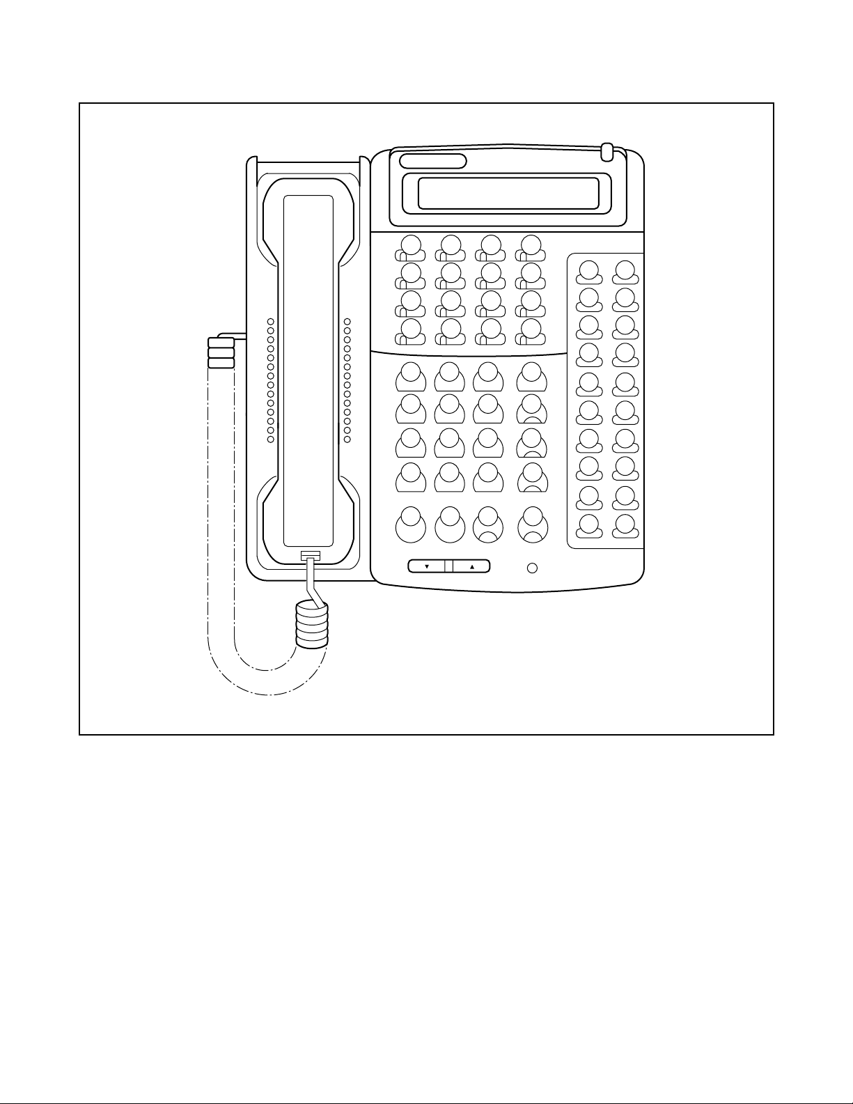
The CAT is a digital multi-function telephone (Multiline Terminal) which is equipped with function keys, a
dial- pad and LCD (16 characters), and interfaces with the system via the MP card.
The MAT is the personal computer, which interfaces with the system via the MP card. For further details, refer
to the MAT Operation Guide.
2.1How to Use the CAT
2.1.1 CAT Key Functions
In the CAT mode, each key on the Multiline Terminal is automatically assigned, as shown in
Figure 2-1. The function of each key is shown in Table 2-1 and Table 2-2.
ND-45669 (E) CHAPTER 2
Page 3
Revision 2.0
Page 19
INFORMATION FOR D ATA PROGRAMMING
ABCD
EF&–
ST
EXE CE S
,–← DE
123DE
456 –
789
A0B ST
← ,CE S
EXE
GQ
HR
IS
JT
KU
LV
MW
NX
OY
PZ
Figure 2-1 CAT Key Assignment for ETJ-16DD-1
CHAPTER 2 ND-45669 (E)
Page 4
Revision 2.0
Page 20

INFORMATION FOR DATA PROGRAMMING
T able 2-1 Function Keys
FUNCTION KEY MEANING
ST Command entry start
EXE Execution of data writ e
CE Cancel of key operation (Clear entry)
S Display of next data (Step forward)
, Separator; to be entered between two different data suc h as first/second data of CM72/74/
90/97.
— Display of previous data (Step backward)
← Cancel of one character out of the ent ered data (Backspace)
DE Data End; to be entered at the end of the command code or at the end of each data entry.
Table 2-2 Digit Keys
DIGIT KEY MEANING
0-9, A-F Data (Data is entered by hexadecimal code 0 - F)
A *: As a dial digit
B #: As a dial digit
C Clear Assigned data by “CCC”
G–Z Data (Data is enter ed as ch a ra ct e r co d e) u sed fo r na m e as sig n ment
ND-45669 (E) CHAPTER 2
Page 5
Revision 2.0
Page 21

INFORMATION FOR D ATA PROGRAMMING
CNF
#
ST
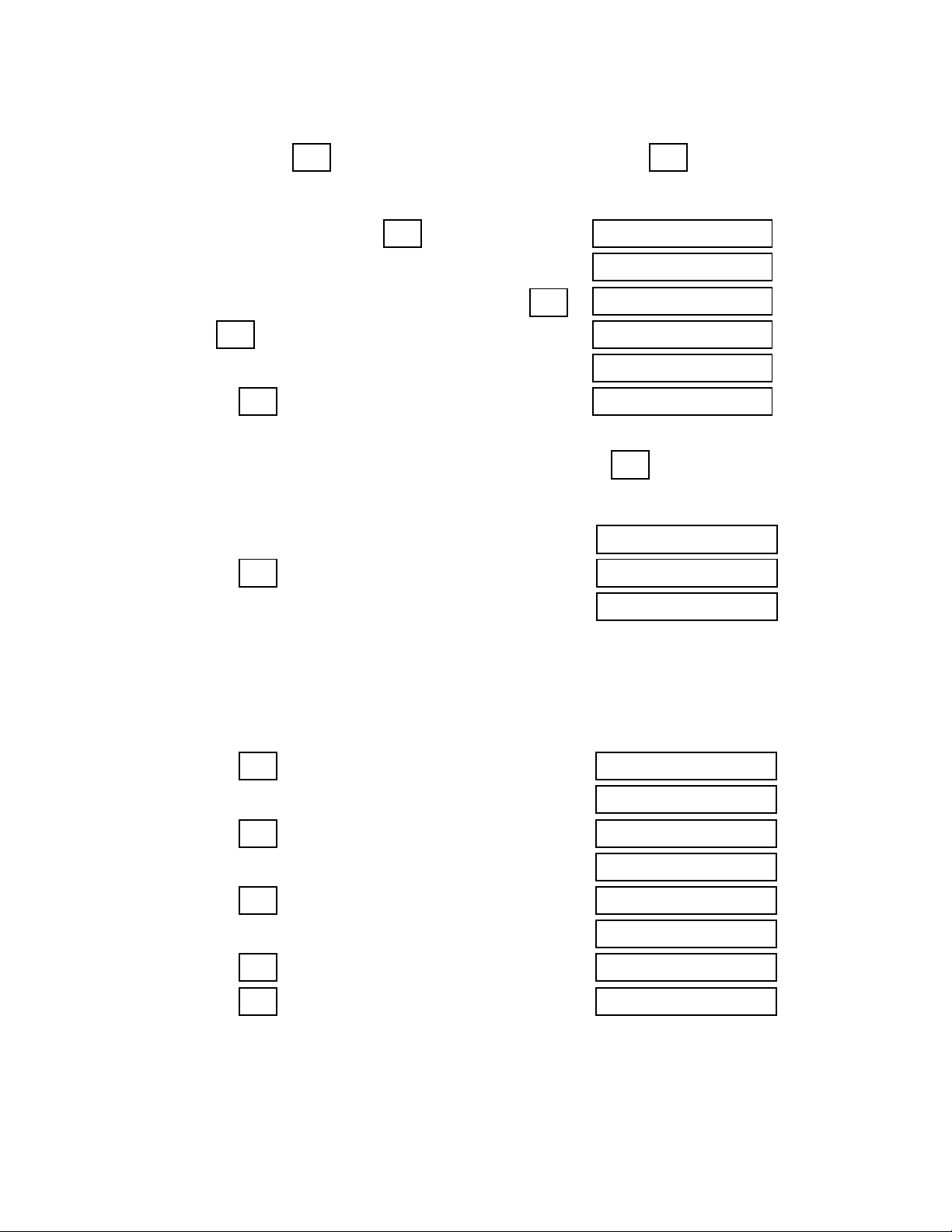
2.1.2 CAT Mode Setting Procedure
To set CAT mode:
1. Press 5. Press
2. Press 6. Press
3. Press – “CAT MODE” displayed on LCD
4. Press – “COMMAND=–” displayed on LCD
To clear CAT mode :
While “COMMAND =– is displayed on the LCD.
1. Lift handset (Off Hook)
2. Replace handset (On Hook)
TRF
– CNF lamp flashes
CNF
– CNF lamp flashes – CNF, SPKR, ANS lamp on
*
– CNF lamp off 7. Press
TRF
Note:
- SPKR lamp off.
- CNF , ANS lamps off.
- LCD returns to clock.
Steps 1 through 6 need to be complete d within 4 seconds.
2.1.3 Notice on the CAT Mode
(1) CAT mode is used in on-line mode. Therefore, system data clear commands (CM00, CM01) cannot be
accessed from the CAT.
(2) To use the CAT after clearing all system data, perform the following operations on the system:
(a) Plug a PN-2DLCB/4DLCA card into the LT00 slot of PIM0.
(b) Connect the CAT (Multiline Terminal) to LEN0000 at the MDF.
(c) Set SW3 on th e MP ca rd to “B”.
(d) Depress SW1 on the MP card. (System Data All Clear)
(e) Set SW3 on the MP card to “0”, and depress SW1. (On-Line mode)
(f) Set the CAT mode on the Multiline Terminal.
(3) During CAT mode, do not change or delete the following data:
• CM10, My Line Number of the CAT.
(4) There are no limitations on the number of Multiline Terminals in the system that can be programmed to
allow CAT capability. Howev er, the number of Multiline Terminals that can be placed into CAT mode, at
the same time, is two.
CHAPTER 2 ND-45669 (E)
Page 6
Revision 2.0
Page 22

INFORMATION FOR DATA PROGRAMMING
2.2 CAT Ope r ati o n
When setting the of fice data, it is necessar y to enter the following three kinds of data:
• Command Code
• First Data
• Second Data
An explanation of the dat a entr y procedure follows:
(a) Operation fo r confirming the exis ting office data
+ Command Code +
ST DE DE
With the above entry completed, the present second data is displayed on the LCD.
If the second data is not assigned yet, ei ther the initial data value or “NONE” is displayed.
(b) Operation for assigning (changing) the office data
+ Command Code +
ST DE DE DE EXE
Wit h EXE pressed, "OK" is displayed on the LCD.
To confirm the data assigned, depress DE after entering the first data.
S –
(c) Use of
•If is pressed after sett ing the second data (after
• If is pressed after setting the second da ta (af ter
button and button
S EXE
is displayed.
– EXE
played.
+ First Data +
+ First Data +
+ Second Data +
has been pressed), the ne xt first data
has been pressed), the la st data is dis-
+
ND-45669 (E) CHAPTER 2
Page 7
Revision 2.0
Page 23
INFORMATION FOR DATA PROGRAMMING
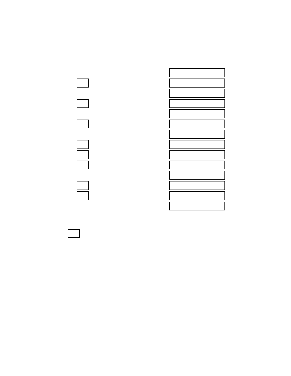
(1)Example: When Station Number 300 is to be assigned to LEN 0000 and Station Number 301 to LEN 0001
by CM10 (Refer to Table 2-3.)
Table 2-3 Assignment Operation
(DISPLAY)
STEP 1 Turn ON power switch.
STEP 2 Press .
STEP 3 Enter “10” (Command Number).
STEP 4 Press .
STEP 5 Enter “0000” (LEN).
STEP 6 Press .
STEP 7 Enter “300” (Station Number).
STEP 8 Press .
STEP 9 Press .
STEP 10 Press .
STEP 11 Enter “301” (Station Number).
STEP 12 Press .
STEP 13 Press .
STEP 14 Turn OFF power switch.
ST COMMAND = _
DE 10> _
DE 10> 0000: NONE-_
EXE OK _
DE 10> 0000: 300-_
S 10> 0001: NONE__
EXE OK _
DE 10> 001 : 301 _
_
COMMAND = 10 _
10> 0000_
10> 0000: NONE-300
10> 0001: NONE-301
Note 1
Note 2
Note 1
Note 2
Note 1:
Note 2:
CHAPTER 2 ND-45669 (E)
Page 8
Revision 2.0
When no data exists, “NONE” is displayed. And when data exists, that data is displayed.
This
operation is for confirming the data assignment. Thus it may be omitted.
DE
Page 24
(2)Example of Operating Steps for Correcting the Data Entry
INFORMATION FOR DATA PROGRAMMING
•In Step 5 in Table 2-3, when is pressed after entering “0001” by mistake, press . Then the state returns to
STEP 4.
STEP 1 CM10 has been entered and has been pressed.
STEP 2 “0001” has been entered instead of “0000” as intended.
STEP 3 “0001” has been assigned as first data after pressing .
STEP 4 If is pressed, the state returns to that of Step 1.
STEP 5 Enter “0000”.
STEP 6 Press , and assign the correct first data.
•If, in Step 11 in Table 2-3, when “302” has been entered instead of “301”, press . Then the cursor moves to the
position of “2”.
STEP 1 In Step 11, enter “302” instead of “301” as intended.
STEP 2 Press
STEP 3 Press digit Key “1”.
CE 10> _
DE 10> 0000: NONE__
←
DE CE
DE 10> _
10> 0001_
DE
10> 0001: NONE-__
10> 0000_
←
10> 0001: NONE-302
.
10> 0001: NONE-30__
10> 0001: NONE-301__
0000 is to be deleted after completing all the operations in Table 2-3.
(3)Example of Deleting Station Number “300” assigned to LEN000
STEP 1 Press .
STEP 2 Enter “10” (Command Number).
STEP 3 Press .
STEP 4 Enter LEN “0000”.
STEP 5 Press .
STEP 6 Enter “CCC”.
STEP 7 Press .
STEP 8 Press .
ST COMMAND = _
DE 10> _
DE 10> 0000: 300-
EXE OK
DE 10> 0000: NONE
COMMAND = 10 _
10> 0000
10> 0000: 300-CCC
ND-45669 (E) CHAPTER 2
Page 9
Revision 2.0
Page 25

INFORMATION FOR DATA PROGRAMMING
2.3Error Messages
When an erroneous operation is performed, or wrong data is entered, an error message is displayed on the
LCD. Error messages and their meanings are shown in Table 2-4.
Table 2-4 Error Messages
ERROR MESSAGE MEANING OF MESSAGE ACTION
DIGIT ERROR Error in the number of digits entered. Press “ST” or “CE” and enter correct data.
DATA ERROR The value of the entered data is incorrect. Same as above.
CODE NOT USED The command code entered is not in use, or
password is needed.
DATA NOT FOUND A Station Number not assigned has been en-
tered.
WAIT BUSY NOW The station or trunk, for which data is to be
changed, is busy.
ASSIGNED ALREADY This error message is displayed when not
enough digits are entered. For example, when
assigning “12” for a service access code,
even if “123” has already been used for another service access code.
HARDWARE ERROR Memory read/write disabled. Check switch setting of MP card or replace
WRONG •The data stored in the memory is wrong.
•This message is displayed when too many
digits are entered. For example, when as signing “123” for a service access code
when “12” has already been used fo r another service code.
SEE CMxx YYYY Double assigned error of the same Station
Number or trunk.
Same as above, or follow the procedure for
entering a password.
Same as above.
Wait until it becomes idle.
Press “ST” or “CE” and enter correct d ata.
MP card with spare.
Clear present data by entering “CCC”, or en-
ter correct data.
Station Number intended is already assigned
to First Data of CMxx Confirm.
USE CMxxxx The data is already assigned by another com-
mand.
TRK NOT ASSIGNED The designated trunk is not assigned. Assign the trunk by CM10.
xx > xxx: ERROR The first data has been changed by “S” or
“-” button, but the station corresponding to
that first data is not assigned.
CHAPTER 2 ND-45669 (E)
Page 10
Revision 2.0
Command Number and YY Number already
assigned are displayed. Confirm.
Change the first data by “S” or “-” button , or
reenter the first data by “CE”.
Page 26

3.COMMAND REFERENCE TABLE
3.1List of Commands
Table 2-5 provides a list of commands.
Table 2-5 List of Commands
COMMAND
CODE FUNCTION
INFORMATION FOR DATA PROGRAMMING
REMARKS
00
01
02
03
04
05
06
07
08
09
10
11
12
13
15
16
17
18
19
1A
1B
1C
1D
20
21
22
23
24
25
26
System Data Memory All Clear
System Data Memory Partial Clear
Setting of System Clock
Log in/Log out of Password Mode
Language Indicated on Multiline Terminal LCD
Card Assignment
MISC Trunk Number Assignment
DTI Trunk/ISDN Trunk Assignment
Basic Service Features
Additional Service Features
Station Number, Trunk Number, and Card Number
Virtual-Line Number
Station Class-1
Station Class-2
Service Restriction Class
Call Pickup Group/Group Diversion Group
UCD Group
Station Hunting Group
Secretary/Group Diversion Station Number
Data Station Number
ISDN Terminal Multipoints Station Number Assignment
PS Station Number Assignment
PS-ID Assignment/PS Operation Data Download
Numbering Plan
Single Digit Access Code
Route Advance
Tenant Development
Kind of Calling Terminal Development
Kind of Special Terminal Development
Closed Number Development
29
2A
30
31
35
36
38
Numbering Plan Tenant Group
ID Code Assignment with MP
Trunk Data
System Attribute Data
Trunk Route Data
Restriction Data for Tandem Connection
AMP Trunk
ND-45669 (E) CHAPTER 2
Page 11
Revision 2.0
Page 27

INFORMATION FOR DATA PROGRAMMING
Table 2-5 List of Commands (Continued)
COMMAND
CODE FUNCTION
40 Function of RS-232C Interface Circuit MP
REMARKS
41
42
44
45
48
System Timer Data
System Counter Data/PAD Data/Trunk Restriction Class Conversion
External Equipment Starting Condition
Purpose of PBR/CFT
Determination of Tone/Tone Source
49 Digital Announcement Trunk PN-2DATA
50
51
52
53
Common Route Indial
Automatic Transfer Destinations
Hot Line
Trunk Answer from Any Station Restriction
56 Internal Zone Paging Group/Intercom Group
58 LDN Diversion
59 TAS/ACD/UCD Relay Interruption Pattern For PN-DK00
5A Virtual Line - Virtual Path Setting
60 ATTCON Tenant Group, Functions For ATTCON
61 External Key Function For PN-DK00
62 Tenants for Each ATTCON Group For ATTCON
63 Restriction of Inter-Tenant Connection
64 Automated Attendant
65 Service Features on Tenant Basis
71
72
73
74
76
77
78
81
85
88
8A
Memory Allocation fo r System Speed Dialing
Stored Number for System Speed Dialing
Memory Allocation for Station Speed Dialing
Stored Number for Station Speed Dialing
Digit Conversion on DID Call
Station/Trunk Name Assignment
Destination of Split Call Forwarding
Toll Restriction Pattern on Each Trunk Restriction Class
Maximum Digits on C.O. Calls
Automatic Pause Entry Table
LCR/Toll Restriction Development Table
CHAPTER 2 ND-45669 (E)
Page 12
Revision 2.0
Page 28

Table 2-5 List of Commands(Continue d)
COMMAND
CODE FUNCTION
INFORMATION FOR DATA PROGRAMMING
REMARKS
90
93
94
96
97
98
9A
A0
A1
A5
Multiline Terminal/SN610 ATTCON/Add-On Module Key Assignment
Prime Line
Multiline Terminal One-Touch Memory
DSS Console Number
DSS Console Key Assignment
Add-On Module Number
Multiline Terminal Soft Key Assignment
Type of Data Adapter
Data Terminal Attribute Data
Nailed Down Connection
A6 Attribute Data for RS-232C Port on AP01 For PN-AP01
A7
A8
A9
AA
AC
AD
AE
AF
B0
B1
B3
CCIS Channel Data
CCIS Routing Label Assignment
ISDN D-Channel Assignment
DTI/DCH/CIR Card Functions
ISDN Functions
ZT Calling Area/PAD Data Assignment
ZT Operation Data Assignment
Visitor PS Data Assignment
PEG Count
Traffic Measurement
UCD PEG Count
Used for maintenance
D5 ID Code Assignment with AP
D6 ID Code All Clear with AP For PN-AP01
D7
D9
DB
DC
E0
E5
E6
E7
E8
E9
EA
EC
EE
F0
F1
F2
F3
F5
F8
OAI Control Data
Centralized Billing Data Port Assignment
Calling Number Development Data
Calling Number Development Table
Initialization
Station Trunk Make Busy
Call Forwarding Set/Reset from MAT/CAT
Password Level
Manual Path Connection
Password Code
Fault Information Store/Display Functions
Battery Release/Line Status Indication
Virtual Tie Line Set/Release
MP Memory Dump
MP Memory Read/Write
FP Memory Dump
FP Memory Read/Write
Line/Trunk Memory/Alarm Memory Read
ID Code for Key FD
ND-45669 (E) CHAPTER 2
Addendum-001 Page 13
AUGUST, 1998 Revision 2.1
Used for maintenance
Used for maintenance
Page 29

INFORMATION FOR DATA PROGRAMMING
3.2Quick Reference Table of Commands Required for Service Feature
This section provides a quick reference table of various commands related to each service feature. The
features are listed alphabetically in the left column. Associated features (shown with bullets) are listed below the main features.
Note:
Table 2-1 provides a list of commands for each business service feature. Table 2-2 provides a list of com-
mands for each hotel/motel service feature. F and S represent First Data (F) and Second Data (S), respectively. For more details about the data, refer to the Command Description for the associated
command.
CHAPTER 2 ND-45669 (E)
Page 14
Revision 2.0
Page 30

Table 2-6 List of Commands for Each Business Feature
For Business System
INFORMATION FOR DATA PROGRAMMING
F: First Data
S : Second Data
— : No Data
COMMAND
FEATURE
CODE Y-YYY
1ST DATA/2ND DATA
(F/S)
Account Code 08 – 362/S
12 02 F/S
15 30 F/1
20 0 – 3 F/085
42 – 10/S
90 00 F/F0085
Add-On Module 10 – F/S
12 05 F/0
30 18 F/0
41 1 09/S
90 00 – 03 F/S
98 0 F/S
Alarm I ndi cations – – –
REMARKS
Alphanumeric Display 08 – 255/1
20 0 – 3 F/A10
35 03 F/S
77 0 – 3 F/S
Analog Port Adapter 10 – F/S
13 09,
F/S
32 – 35
90 00 F/S
93 – F/S
ND-45669 (E) CHAPTER 2
Page 15
Revision 2.0
Page 31

INFORMATION FOR D ATA PROGRAMMING
Table 2-6 List of Commands for Each Business Feature (Continued)
For Business System
F: First Data
S : Second Data
— : No Data
COMMAND
FEATURE
CODE Y-YYY
1ST DATA/2ND DATA
(F/S)
Announcement Ser v ice 08 – 124/S
10 – F/S
12 02 F/S
15 34 – 39 F/1
20 0 – 3 F/A00 – A09
30 03, 05 F/S
35 69 – 73 F/1
41 0 45, 53/S
48 0 F/0500
49 00, 05 –
F/S
07
65 50, 51 F/0
Answer Key 12 02 F/S
15 72 F/0
REMARKS
Attendant-Assisted Calling 08 – 018, 048, 142, 143/S
20 0 - 3 F/800
60 00, 01 F/S
62 0 - 3 F/0
Attendant Camp-On 08 – 068, 441/S
20 0 - 3 F/021
41 0 00/S
Attendant Console
(SN610 ATTCON)
10 – F/S
30 02, 03 F/14
60 00, 01, 07,
F/S
17
62 0 - 3 F/S
90 00 F/S
CHAPTER 2 ND-45669 (E)
Page 16
Revision 2.0
Page 32

Table 2-6 List of Commands for Each Business Feature (Continued)
For Business System
INFORMATION FOR DATA PROGRAMMING
F: First Data
S : Second Data
— : No Data
FEATURE
Attendant Console
(SN716 DESK CON)
COMMAND
CODE Y-YYY
10 – F/S
30 02, 03 F/14
1ST DATA/2ND DATA
(F/S)
60 00, 01 , 15 F/S
62 0 - 3 F/S
90 00 F/S
• Attendant Calling/Called Name
Display
08 – 255/1
20 0 - 3 F/A10
35 03 F/S
77 0 - 3 F/S
• Attendant Called/Calling Number – – –
• Attendant Call Selection 35 15 F/S
90 00 F/S
• Attendant Console Lockout
Password
08 – 353/S
20 0 - 3 F/A55
REMARKS
60 30 0/S
90 00 F/F6110
• Attendant Do Not Disturb Setup
and Cancel
• Attendant Interposition Calling/
Transfer
13 00 F/0
90 00 F/S
08 – 143/S
20 0 - 3 F/095
90 00 F/F6067
•Attendant Lamp Check – – –
• Attendant Listed Directory
Number
08 – 204, 205/0
35 15 F/S
50 01, 02 F/S
58 00 - 09 F/S
90 00 F/S
ND-45669 (E) CHAPTER 2
Page 17
Revision 2.0
Page 33

INFORMATION FOR D ATA PROGRAMMING
Table 2-6 List of Commands for Each Business Feature (Continued)
For Business System
F: First Data
S : Second Data
— : No Data
COMMAND
FEATURE
CODE Y-YYY
1ST DATA/2ND DATA
(F/S)
• Attendant Loop Release 08 – 014/0
20 0 - 3 F/021
• Attendant Programming 08 – 229/S
20 0 - 3 F/A56
60 30 1/S
90 00 F/611
• Attendant Training Jack – – –
• Audible Indication Control – – –
• Call Processing Indication – – –
• Cal l Q u eu i ng 42 – 00/ S
• Call Splitting 90 00 F/S
• Call Waiting Display 42 – 00/S
• Common Route Indial 08 – 204, 205/0
REMARKS
50 01 F/S
58 00 – 09 F/S
90 00 F/S
• Dialed Number I d entification
Service
08 – 204, 205/0
35 15 F/S
50 01, 02 F/S
58 02, 03, 08,
F/S
09, 10
90 00 F/S
• Incoming Call Identificat ion – – –
• Individual Trunk Access 20 0 – 3 F/081
30 19 F/S
• Multiple Console Operation Refer to SN61 0 ATTCON.
CHAPTER 2 ND-45669 (E)
Page 18
Revision 2.0
Page 34

Table 2-6 List of Commands for Each Business Feature (Continued)
For Business System
INFORMATION FOR DATA PROGRAMMING
F: First Data
S : Second Data
— : No Data
COMMAND
FEATURE
CODE Y-YYY
1ST DATA/2ND DATA
(F/S)
• Monitor 08 259 0
15 103 –
15 104 –
20 0 – 3 –
90 00 F0033
• Multi-Function Key 60 17 F/1
90 00 F/F6XXX
• Pushbutton Calling - Attendant
35 01 F/7
Only
• Se r ia l Call 90 00 F/S
•Timer Display – – –
• Trunk Group Busy Display 30 09 F/S
44 – F/S
90 00 F/S
REMARKS
• Unsupervised Trunk to Trunk
08 – 206/1
Transfer by Attendant
Attendant Delay Announcement 08 – 165/S
10 – F/S
20 0 – 3 F/A00-A02
35 74 F/S
41 0 16, 47/S
49 00, 0A F/S
Attendant Lockout 08 – 353/S
Attendant Overflow 08 – 067/0
30 02, 03 , 05 F/S
41 0 0 1/S
ND-45669 (E) CHAPTER 2
Page 19
Revision 2.0
Page 35

INFORMATION FOR DATA PROGRAMMING
Table 2-6 List of Commands for Each Business Feature (Continued)
For Business System
F: First Data
S: Second Data
— : No Data
COMMAND
FEATURE
CODE Y-YYY
1ST DATA/2 ND DATA
(F/S)
Attendant Override 08 – 012, 045, 076/S
12 02 F/S
15 09 F/1
20 0 – 3 F/081
30 19 F/S
90 00 F/F6107
Authorizati on Code 05 – F/07
08 – 216, 362/S
12 02 F/S
15 31 F/S
20 0 – 3 F/086
42 – 11/S
D5 0, 1, 3 F/S
REMARKS
2A 0 – 4 F/S
Automated Attendant 08 – 180, 359, 363/S
10 – F/S
20 0 – 3 F/A00 – A02
30 02, 03,
F/S
30–33, 37
41 0 34, 39, 43, 59/S
45 2 F/0
48 2 06/S
49 00 – 02 F/S
63 2 F/S
64 0, 2 F/S
CHAPTER 2 ND -45669 (E)
Page 20 Addendum-002
Revision 2.2 JANU ARY , 1999
Page 36

Table 2-6 List of Commands for Each Business Feature (Continued)
For Business System
INFORMATION FOR DATA PROGRAMMING
F: First Data
S : Second Data
— : No Data
COMMAND
FEATURE
CODE Y-YYY
1ST DATA/2ND DATA
(F/S)
Automatic Call Distribution (ACD) 08 – 212, 214, 215, 227, 259, 265,
357, 442/S
10 F/S
12 02 F/S
15 33, 103,
F/1
104
17 0 – 2,
F/S
4 – 7, A, B
20 0 – 3 F/033, 044, 0045, A00 – A02
35 12, 18, 60,
F/S
78
41 0 16, 47/S
42 – 15, 16/S
44 – F/S
49 00 F/S
REMARKS
51 17 F/S
59 – 00/S
76 0 , 1, 6 F/ S
90 0 F/F0033, F0044, F0120,
F1280 – 1295
97 – F/F1055
Automatic Call Distribu tion (ACD)
with Management
Information System (MIS)
08 – 068/S Refer to ACD-MIS
30 13, 14 F/06
Automatic Camp – On 08 – 068/S
30 13, 14 F/06
System Manual
ND-45669 (E) CHAPTER 2
Page 21
Revision 2.0
Page 37

INFORMATION FOR D ATA PROGRAMMING
Table 2-6 List of Commands for Each Business Feature (Continued)
For Business System
F: First Data
S : Second Data
— : No Data
COMMAND
FEATURE
CODE Y-YYY
1ST DATA/2ND DATA
(F/S)
Automatic Numb er I dentification 05 – F08
06 04 F/S
08 – 462, 463, 472/S
09 – 52/0
20 Y F/A26-A29
30 00, 02 , 03 F/S
31 1, 2, 3, A,
F/S
B
35 00, 04, 05,
F/S
09, 10, 17,
19, 20, 37,
48
8A 4XX F/800
Automatic Recall 41 0 00, 05 – 07, 11, 26/S
Background Music ( BGM) 10 – F/S
REMARKS
12 02 F/S
15 32 F/1
20 0 – 3 F/039
30 00 F/S
35 00 F/05
48 4 F/S
Boss/Secretary Calling 08 – 294/S
12 02, 05 F/S
13 03, 08 , 12 F/S
15 43, 44 F/S
20 0 – 3 F/040, 041
51 15 F/S
90 00 F/S
Broker’s Call Refer to Call Hold
CHAPTER 2 ND-45669 (E)
Page 22
Revision 2.0
Page 38

Table 2-6 List of Commands for Each Business Feature (Continued)
For Business System
INFORMATION FOR DATA PROGRAMMING
F: First Data
S : Second Data
— : No Data
COMMAND
FEATURE
CODE Y-YYY
1ST DATA/2ND DATA
(F/S)
Call Back 08 – 156/0
12 02 F/S
15 03, 46 F/1
20 0 - 3 F/002 – 005
90 00 F/F0004
Caller ID Class 05 – F/08
06 04 F/S
08 – 462, 463, 472/S
09 – 52/0
30 02, 03 F/S
31 1, 2 F/S
35 00, 37, 44,
F/S
48, 129
90 00 F/F1099, F6122
REMARKS
AA 07 F/S
DB 00, 01, 02,
F/S
04, 05, 06,
07, 12, 30,
90 - 92
DC 00 - 63 F/S
Caller ID Displa y 90 00 F/F5010
Call Forwarding E6 00 - 05 F/S Set/Reset from MAT/CAT
• Attendant Call Forwarding Setup
–– –
and Cancel
ND-45669 (E) CHAPTER 2
Page 23
Revision 2.0
Page 39

INFORMATION FOR D ATA PROGRAMMING
Table 2-6 List of Commands for Each Business Feature (Continued)
For Business System
F: First Data
S : Second Data
— : No Data
COMMAND
FEATURE
CODE Y-YYY
1ST DATA/2ND DATA
(F/S)
• Call Forwardi ng - All Calls 08 – 222, 386, 387/S
09 – 33/S
12 02 F/S
15 00, 26 F/1
20 0 - 3 F /010, 011
35 05 F/1
36 – F/0
48 2 13/S
65 23 - 25 F/1
90 00 F/F0010
E6 00 F/S
• Call Forwarding - Busy Line 08 – 222, 240, 386, 387/S
12 02 F/S
REMARKS
15 11, 12,
F/1
28, 29
20 0 – 3 F/012, 013, 014, 015
35 05 F/1
36 – F/0
65 23 – 25 F/1
90 00 F/F0012, F0014
CHAPTER 2 ND-45669 (E)
Page 24
Revision 2.0
Page 40

Table 2-6 List of Commands for Each Business Feature (Continued)
For Business System
INFORMATION FOR DATA PROGRAMMING
F: First Data
S : Second Data
— : No Data
COMMAND
FEATURE
CODE Y-YYY
1ST DATA/2ND DATA
(F/S)
• Call Forwarding - No Answer 08 – 222, 386, 387/S
12 02 F/S
15 10, 12,
F/1
27, 29
20 0 – 3 F/012, 013, 016, 017
35 05 F/1
36 – F/0
41 0 01, 15/S
65 23 – 25 F/1
90 00 F/F0012, F0016
• Call Forwarding - Destination 12 02 F/S
15 15 F/1
20 0 – 3 F/018, 019
90 00 F/F0018, F0019
REMARKS
• Multiple Call Forwarding -
All Calls
• Multiple Call Forwarding -
Busy Line
• Multiple Call Forwarding -
No Answer
42 – 14/S
42 – 14/S
41 0 46/S
ND-45669 (E) CHAPTER 2
Page 25
Revision 2.0
Page 41

INFORMATION FOR D ATA PROGRAMMING
Table 2-6 List of Commands for Each Business Feature (Continued)
For Business System
F: First Data
S : Second Data
— : No Data
COMMAND
FEATURE
CODE Y-YYY
1ST DATA/2ND DATA
(F/S)
• Split Call F orwarding - All Calls 08 – 222, 386, 387/S
12 02 F/S
15 00, 26 F/1
20 0 – 3 F/010, 011, A80, A81
35 05 F/1
36 – F/0
48 2 13/S
65 23 – 25 F/S
78 – F/S
90 00 F/F0010, F0A80
• Split Call Forwarding - Busy Line 08 – 222, 240, 386, 387/S
12 02 F/S
15 11, 12,
F/1
28, 29
REMARKS
20 0 – 3 F/012 - 015, A82, A83
35 05 F/1
36 – F/0
65 23 – 25 F/S
78 – F/S
90 00 F/F0012, F0014, F0A82
CHAPTER 2 ND-45669 (E)
Page 26
Revision 2.0
Page 42

Table 2-6 List of Commands for Each Business Feature (Continued)
For Business System
INFORMATION FOR DATA PROGRAMMING
F: First Data
S : Second Data
— : No Data
FEATURE
• Split Call Forwarding -
No Answer
COMMAND
CODE Y-YYY
08 – 222, 386, 387/S
12 02 F/S
15 10, 12,
1ST DATA/2ND DATA
(F/S)
F/1
27, 29
20 0 – 3 F/012, 013, 016, 017, A82,
A83
35 05 F/1
36 – F/0
41 0 01, 15/S
65 23 – 25 F/S
78 – F/S
90 00 F/F0012, F0016, F0A82
• Call Forwarding - Override – – –
• Group Diversion 08 – 026/0
REMARKS
16 2 F/S
19 6 F/S
41 0 01/S
Call Park – – –
• Call Park - System 08 – 133/S
12 07 F/S
15 96 F/S
20 0 – 3 F/008, 009
41 0 05/S
90 00 F/F5000, F6144
• Call Park - Tenant 08 – 133/S
20 0 – 3 F/062
41 0 05/S
90 00 F/F3XXX
ND-45669 (E) CHAPTER 2
Page 27
Revision 2.0
Page 43

INFORMATION FOR D ATA PROGRAMMING
Table 2-6 List of Commands for Each Business Feature (Continued)
For Business System
F: First Data
S : Second Data
— : No Data
COMMAND
FEATURE
CODE Y-YYY
1ST DATA/2ND DATA
(F/S)
Call Pickup – – –
• Call Pickup - Direct 12 02 F/S
15 14 F/1
20 0 - 3 F/021
90 00 F/F0021
• Call Pickup - Group 16 0 F/S
20 0 - 3 F/020
90 00 F/F0020
• Call Pickup - Designated Group 12 02 F/S
15 14 F/1
16 0 F/S
20 0 - 3 F/037
Call Redirect 51 18, 22 F/S
REMARKS
90 00 F /F5011/F5012
Call Transfer – – –
• Call Transfer - All Calls 08 – 068, 155, 319/S
• Call Transfer - Attendant 08 – 063, 142/S
20 0 - 3 F/800
62 0 - 3 F/0
Camp-On 08 – 050, 051, 068, 069,
146 – 148, 208, 322/S
12 02 F/S
15 16, 43 , 44 F/ 1
20 0 - 3 F/007 , A25
41 0 26/S
CCSA Access 20 0 - 3 F/100 – 163
35 00, 15 F/S
90 00 F/F6030 – F6037
CHAPTER 2 ND-45669 (E)
Page 28
Revision 2.0
Page 44

Table 2-6 List of Commands for Each Business Feature (Continued)
For Business System
INFORMATION FOR DATA PROGRAMMING
F: First Data
S : Second Data
— : No Data
COMMAND
FEATURE
CODE Y-YYY
1ST DATA/2ND DATA
(F/S)
Centrex Compatibility 20 0 – 3 F/A58
35 16, 86 F/S
93 – F/S
Class of Service 12 00 – 03,
F/S
07
15 80,
F/S
82 – 84,
88 – 91,
96 – 98
35 51 – 58,
F/S
61 – 68
Code Restriction 08 – 035, 044, 119/S
12 01 F/S
35 11,
F/S
51 – 55,
76
REMARKS
81 01 – 13 F/S
85 0 – 4 F/S
8A 400
100 – 115,
000 – 063,
500 – 755,
200 – 207,
–
404,
F/S
300 – 303
Conference 08 – 101 – 104, 246/S
45 6, 7 F/1
ND-45669 (E) CHAPTER 2
Page 29
Revision 2.0
Page 45

INFORMATION FOR D ATA PROGRAMMING
Table 2-6 List of Commands for Each Business Feature (Continued)
For Business System
F: First Data
S : Second Data
— : No Data
COMMAND
FEATURE
CODE Y-YYY
1ST DATA/2ND DATA
(F/S)
Consecutive Speed Dialing 05 – F/19
08 – 035, 168, 171, 252/ S
12 02 F/S
15 07 F/1
20 0 – 3 F/064 – 066
73 – F/S
74 – F/S
90 00 F/S
94 – F/S
CMD000 – 56/1
Consultation Hold 08 – 137/0
12 07 F/S
15 88 – 91 F/1
REMARKS
Customer Administration
Terminal (CAT)
12 02 F/S
15 56 F/1
E7 00 – 06,
F/S
10 – 16
E9 – 0 – 9/S
Data Line Security 13 07 F/0
Delayed Ringing 41 1 09/S
90 03 F/0
Diagnostics Refer to Maintenance
Manual.
CHAPTER 2 ND-45669 (E)
Page 30
Revision 2.0
Page 46

Table 2-6 List of Commands for Each Business Feature (Continued)
For Business System
INFORMATION FOR DATA PROGRAMMING
F: First Data
S : Second Data
— : No Data
COMMAND
FEATURE
CODE Y-YYY
1ST DATA/2ND DATA
(F/S)
REMARKS
Dial Conversion 08 – 050, 051/0
10 – F/S
12 00 F/3
35 01,
F/S
23 – 26,
45, 46
45 0, 1 F/1
Direct Digital Interface (DDI) Refer to DDI System
Manual.
Direct Inward Dialing (DID) 08 – 180/S
10 – F/S
30 00 – 05 F/S
35 00, 02, 05,
F/S
12, 18
41 0 01, 45/S
45 1 F/S
49 00 F/S
51 00, 03 , 06 F/S
76 0, 1 F/S
ND-45669 (E) CHAPTER 2
Page 31
Revision 2.0
Page 47

INFORMATION FOR D ATA PROGRAMMING
Table 2-6 List of Commands for Each Business Feature (Continued)
For Business System
F: First Data
S : Second Data
— : No Data
FEATURE
Direct Inward System Access
(DISA)
COMMAND
CODE Y-YYY
05 – F/07
08 – 180, 217, 352/S
1ST DATA/2ND DATA
(F/S)
10 – F/EBXXX
15 33 F/S
20 0 – 3 F/A00, A01
2A 5 – 8 F/S
30 02, 03, 30,
F/S
31
35 18 F/0
41 0 39/S
42 – 13/S
76 0, 1 F/D16
D5 0, 1, 3 F/S
Direct Inward Terminator (DIT) 08 – 179/S
REMARKS
30 02, 04, 13,
15
41 0 01/S
Direct Outward Dialing (DOD) 10 – F/S
20 0 – 3 F/100 – 163
30 00, 01 , 08 F/S
35 00 – 02,
04, 05, 08,
09, 20 –
26, 45 , 46
41 0 2 7/S
90 00 F/S
CHAPTER 2 ND-45669 (E)
Page 32
Revision 2.0
F/S
F/S
Page 48

Table 2-6 List of Commands for Each Business Feature (Continued)
For Business System
INFORMATION FOR DATA PROGRAMMING
F: First Data
S : Second Data
— : No Data
FEATURE
Direct Station Selection/Busy Lamp
Field (DSS/BLF) Console
COMMAND
CODE Y-YYY
08 – 269/274/S
10 – F/S
1ST DATA/2ND DATA
(F/S)
96 – F/S
97 – F/S
Distinctive Ringing 08 – 137, 138, 179, 180/S
35 32, 33 F/S
Do Not Disturb 08 – 240, 241/S
12 02 F/1
13 00 F/0
15 19 F/1
20 0 - 3 F /022, 023
48 2 14/S
51 10 F/S
REMARKS
90 00 F/S
Dual Hold 12 02 F/S
15 64 F/1
E & M Tie Line A c cess 10 – F/S
35 00 - 02,
F/S
04, 05,
08 - 10,
13, 19,
20, 21,
23 - 26,
33, 34,
45, 46,
104, 105
42 – 50 - 65/S
45 1 F/0
49 00 F/0000, 0E00
51 01, 04 , 07 F/EB XXX
63 2 F/S
ND-45669 (E) CHAPTER 2
Page 33
Revision 2.0
Page 49

INFORMATION FOR D ATA PROGRAMMING
Table 2-6 List of Commands for Each Business Feature (Continued)
For Business System
F: First Data
S : Second Data
— : No Data
COMMAND
FEATURE
CODE Y-YYY
1ST DATA/2ND DATA
(F/S)
Elap sed Call Timer – – –
Enhanced 911 05 – F/08
06 04 F/S
08 – 474, 475/S
09 – 52/0
12 12, 13 F/S
13 25 F/S
20 0 - 3 F/A26-A28
31 2 0 - 3/0
35 03, 04,
F/S
14, 20,
36, 38,
76, 129
50 05 F/S
85 0 - 7 F/S
REMARKS
8A YYY F/S
AA 07 F/3
Executive Calling 13 21 F/0
Executive Override 08 – 045, 115/S
12 02 F/S
15 05, 09 F/1
20 0 - 3 F/006
45 6 F/1
90 00 F/F0006
CHAPTER 2 ND-45669 (E)
Page 34
Revision 2.0
Page 50

Table 2-6 List of Commands for Each Business Feature (Continued)
For Business System
INFORMATION FOR DATA PROGRAMMING
F: First Data
S : Second Data
— : No Data
COMMAND
FEATURE
CODE Y-YYY
1ST DATA/2ND DATA
(F/S)
External Pag ing with Meet-Me 08 – 094, 096, 149, 157, 445 /S
10 – F/S
12 02 F/S
15 08 F/1
20 0 - 3 F/100 - 163, 070 - 079, 080
30 00, 28 F/S
35 00, 08 F/S
44 – F/S
90 00 F /6150 - F6159
Feature Acti vati on from Seco ndary
–– –
Extension
FAX Arriv al Indicator 1 2 03, 05 F/00 - 03
13 29 F/0
51 14 00 - 03/S
REMARKS
52 00 - 99 F/S
90 00 F/S
Flexible Li ne Key Assignmen t 08 252 F/S
12 02 F/S
15 07 F/S
73 – F/S
90 00 F11XX
94 – F/S
Flexible Numb ering Plan 08 050, 051,
F/S
069, 148,
156, 208
10 – F/S
20 – F/801 - 804
29 0 - 3 F/S
ND-45669 (E) CHAPTER 2
Page 35
Revision 2.0
Page 51

INFORMATION FOR D ATA PROGRAMMING
Table 2-6 List of Commands for Each Business Feature (Continued)
For Business System
F: First Data
S : Second Data
— : No Data
COMMAND
FEATURE
CODE Y-YYY
1ST DATA/2ND DATA
(F/S)
Flexibl e Ringing Assignment 08 – 390/1
12 02, 07 F/S
15 68, 83 , 84 F/S
35 34 F/S
90 01 F/ 0
Forced Account Code 05 01 F/07
08 – 216, 362/S
12 02 F/S
15 31 F/1
20 0 - 3 F/087
42 – 11, 12/S
2A 0 - 4 F/S
D5 0, 1, 3 F/S
REMARKS
D6 0 0000/CCC
Group Listening 12 02 F/S
15 70 F/0
Handsfree Answerback – – –
Handsfree Dialing and
–– –
Monitoring
Hold – – –
• Cal l H o ld 12 02 F/S
15 01 F/ 1
20 0 - 3 F/046
90 00 F/F0046
• Exclusive Hold 08 – 13 0/1
41 0 0 6/S
• No n e xc lu s ive H o ld – – –
CHAPTER 2 ND-45669 (E)
Page 36
Revision 2.0
Page 52

Table 2-6 List of Commands for Each Business Feature (Continued)
For Business System
INFORMATION FOR DATA PROGRAMMING
F: First Data
S : Second Data
— : No Data
COMMAND
FEATURE
CODE Y-YYY
1ST DATA/2ND DATA
(F/S)
Hotline 08 – 057/S
11 – F/S
12 03 F/04
52 00 - 99 F/S
71 – 65/S
72 – F/S
90 00 F/S
Indivi dual Attendant Access 06 01 F/S
08 – 143/S
10 – F/E000 - E007
20 0 - 3 F/095
Intercept Announcement 10 – F/EB000 - EB127
12 02 F/S
REMARKS
15 33 F/1
20 0 - 3 F/A00 - 02
49 00 F0A00
51 07 F/S
Intercom – – –
• Manual Intercom 08 – 238/S
11 – F/A200 - A724
12 02, 03 F/S
15 09 F/0
56 11 F/S
90 00 F/A200 - A724
ND-45669 (E) CHAPTER 2
Page 37
Revision 2.0
Page 53

INFORMATION FOR D ATA PROGRAMMING
Table 2-6 List of Commands for Each Business Feature (Continued)
For Business System
F: First Data
S : Second Data
— : No Data
COMMAND
FEATURE
CODE Y-YYY
1ST DATA/2ND DATA
(F/S)
• Automatic Intercom 08 – 237/S
11 – F/A000 - A131
12 03 F/05
13 11 F/S
56 10 F/S
90 00 F/A000 - A131
• Dial Intercom 08 – 239/S
11 – F/B000 - B924
12 02, 03 F/S
15 09 F/0
56 12 F/S
90 00 F/B000 - B924
Internal Tone/Voice Signa ling 08 – 050, 051, 069, 148,
156, 270/S
REMARKS
12 02, 07 F/S
15 67, 99 F/S
20 0 - 3 F/A63
Internal Zone Paging with
Meet-Me
08 – 158/S
12 02 F/S
15 49 F/1
20 0 - 3 F/A30 - A45, A64
56 00 - 07 F/S
90 00 F/F1270 - F1277
Last Number Redial 08 – 177, 178/S
20 0 - 3 F/069
90 00 F/F0069, F1000, F6121
CHAPTER 2 ND-45669 (E)
Page 38
Revision 2.0
Page 54

Table 2-6 List of Commands for Each Business Feature (Continued)
For Business System
INFORMATION FOR DATA PROGRAMMING
F: First Data
S : Second Data
— : No Data
COMMAND
FEATURE
CODE Y-YYY
1ST DATA/2ND DATA
(F/S)
Least Cost Routing 3/6 Digit 20 0 - 3 F/A26 - A28
35 11,
F/S
51 - 55
81 – F/S
85 01 - 13 F/S
8A 5-7, A00
F/S
100 - 115
200 - 207
300 - 303
405 - 407,
410
000 - 063
500 - 755
900 - 949
800 - 849
Line Lockout 08 – 153, 274/S
13 04 F/1
REMARKS
41 0 22/S
42 – 01/S
Line Preselection 08 – 199/S
Maintenance Administration
Terminal (MAT)
03 – F/S
E7 00 - 06,
F/S
10 - 16
E9 – 0 - 9/S
• Configurati on Report – – –
• Ma in t en an c e Pr in t ou t – – –
• Peg Count B0 0, 2 F/S
B3 0 - 5 F/S
• Remove and Restore Service E5 0, 1 F/S
Message Center Interface (MCI) Refer to Message Center
Interface (MCI) System
Manual.
ND-45669 (E) CHAPTER 2
Page 39
Revision 2.0
Page 55

INFORMATION FOR D ATA PROGRAMMING
Table 2-6 List of Commands for Each Business Feature (Continued)
For Business System
F: First Data
S : Second Data
— : No Data
COMMAND
FEATURE
CODE Y-YYY
1ST DATA/2ND DATA
(F/S)
Message Reminder 08 – 050, 051, 069, 148, 156,
208, 234 - 236,
280 - 294/S
12 02 F/S
13 03 F/0
15 47, 48 F/1
20 0 - 3 F/A46 - A49
51 15 F/S
90 00 F/F1005
Miscellaneous Trunk Access – – –
• Code Calling Equipm ent
Access
10 – F/S
20 0 - 3 F/100 - 163
30 00, 01 F/S
35 00, 01 , 08 F/S
REMARKS
44 – F/S
• Dictation Equi pm ent Access 10 – F/S
20 0 - 3 F/100 - 163
30 00, 01 F/S
35 00, 01 , 08 F/S
• Foreign Exchange (FX) Access 35 00 F/01
• Radio Paging Equipm ent Access 08 – 094, 095, 149, 157, 162/S
10 – F/S
12 02 F/S
15 08 F/1
20 0 - 3 F/100 - 163, 070 - 079
30 00, 28 F/S
35 00, 08 , 13 F/S
41 0 2 0/S
CHAPTER 2 ND-45669 (E)
Page 40
Revision 2.0
Page 56

Table 2-6 List of Commands for Each Business Feature (Continued)
For Business System
INFORMATION FOR DATA PROGRAMMING
F: First Data
S : Second Data
— : No Data
FEATURE
• Wide Area Telephone Service
(WATS) Access
Multiline Terminal Attendant
Position
COMMAND
CODE Y-YYY
1ST DATA/2ND DATA
(F/S)
35 00 F/02
08 – 206, 244, 245, 250/ S
10 – F/S
11 – F/S
12 02, 03 F/S
15 60, 71 , 73 F/S
17 1, 2 F/S
20 0 - 3 F/088
30 02, 04 F/S
51 12 F/S
90 00 F/S
96 – F/S
97 – F/S
REMARKS
Music On Hold 08 – 183, 388/S
10 – F/S
12 02 F/S
15 33 F/1
20 0 - 3 F/A00 - A02
44 – F/0000 - 0009
48 0 F/S
49 00, 05 F/S
64 1 F/00 - 09
Night Service – – –
• Attendant Night Transfer 08 – 018/S
51 13 F/S
• Call Rerouting – – – See Night Connection
Fixed/Flexible, TAS, DIT,
DID, E&M Tie Line.
ND-45669 (E) CHAPTER 2
Page 41
Revision 2.0
Page 57

INFORMATION FOR D ATA PROGRAMMING
Table 2-6 List of Commands for Each Business Feature (Continued)
For Business System
F: First Data
S : Second Data
— : No Data
FEATURE
• Day/Night Mode Change by
Attendant Console
COMMAND
CODE Y-YYY
20 0 – 3 F/A55
60 30 1/S
1ST DATA/2ND DATA
(F/S)
REMARKS
90 00 F /F6110
• Day/Night Mode Change by
Station Dialing
08 – 244, 245/0
12 02 F/S
15 60 F/1
20 0 – 3 F/043
90 00 F /F0043
• Night Connection - Fix ed 30 03, 05, 14,
F/S
16
41 0 01/S
• Night Connection - Flexible – – – See Night Connection
Fixed and Call Forw arding - All Calls.
• Trunk Answer Any Sta tion (TAS) 10 – F/E800 – E831
12 01, 02 F/S
15 53 F/1
20 0 – 3 F/047 – 051
30 03, 17 F/S
44 – F/S
53 0 – 4 F/S
59 – F/S
63 0 F/S
Off-Hook Alarm 12 07 F/S
13 02 F/0
15 97, 98 F/S
41 0 22/S
51 12 F/S
90 00 F/F6056
CHAPTER 2 ND-45669 (E)
Page 42
Revision 2.0
Page 58

Table 2-6 List of Commands for Each Business Feature (Continued)
For Business System
INFORMATION FOR DATA PROGRAMMING
F: First Data
S : Second Data
— : No Data
COMMAND
FEATURE
CODE Y-YYY
1ST DATA/2ND DATA
(F/S)
Off-Premises Extension 13 09 F/0
Pad Lock 05 – F/07
08 – 216, 281, 362/S
12 02 F/S
15 31, 75 F/S
20 0 – 3 F/029, 086
2A 0, 1, 3 F/S
42 – 11/S
D5 0, 1, 3 F/S
D000 – 150/1
D015 – F/S
D016 – xx06/1
D031 – F/S
REMARKS
Periodic Time Indication Tone 08 – 135, 136/S
12 02 F/S
13 07 F/1
15 61 F/1
41 0 09/S
Pooled Line Access 30 00 – 03 F/S
90 00 F/F411 – F4163
Power Failure Transfer 10 – F/S
Priority Call 08 – 250, 251/S
12 02 F/S
15 17, 18 F/1
20 0 – 3 F/088, 089
51 12 F/S
90 00 F/F6054, F6055
ND-45669 (E) CHAPTER 2
Page 43
Revision 2.0
Page 59

INFORMATION FOR D ATA PROGRAMMING
Table 2-6 List of Commands for Each Business Feature (Continued)
For Business System
F: First Data
S: Second Data
—: No Data
COMMAND
FEATURE
CODE Y-YYY
1ST DATA/2ND DATA
(F/S)
Privacy/Privacy Release 12 02 F/S
15 63 F/1
Private Line 12 16 F/S
35 98 F/S
42 – 08/S
Proprietary Multiline Terminal – – –
• Automatic Idle Return 0 8 – 172/1
• Called Station Status Display – – –
• Calling Name and Number
08 – 335
Display
• Dynamic Dial Pad 12 02 F/S
15 120 F/0
93 – F/S
• Handsfree Unit – – –
REMARKS
• I-Hold/I-Use Indication – – –
• Microphone Control – – –
• Multiple Line Operation 90 01 F/S
• Mute Key 90 00 F/F5013
• Off-Hook Voice Announcement 08 – 270, 279/1
11 – F/CX – CXXXX
12 02, 07 F/S
13 28 F/S
15 67, 72 , 99 F/S
20 0 – 3 F/A63
90 00 F/CX – CXXXX
• Prime Line Pickup 93 – F/S
CHAPTER 2 ND-45669 (E)
Pa ge 44 Ad dendum-001
Revision 2.1 AUGUST, 1998
Page 60

Table 2-6 List of Commands for Each Business Feature (Continued)
For Business System
INFORMATION FOR DATA PROGRAMMING
F: First Data
S: Second Data
—: No Data
COMMAND
FEATURE
CODE Y-YYY
1ST DATA/2ND DATA
(F/S)
• Recall Key 35 16, 86 F/1
41 2 17/S
90 00 F/F1009
• Relay Control Function Key 10 – F/E8XX
44 – F/1500
90 00 F/F7XXX
REMARKS
ND-45669 (E) CHAPTER 2
Addendum-001 Page 44-1
AUGUST, 1998 Revision 2.1
Page 61

This page is for your notes.
CHAPTER 2 ND-45669 (E)
Pa ge 44-2 Addendum- 00 1
Revision 2.1 AUGUST, 1998
Page 62

Table 2-6 List of Commands for Each Business Feature (Continued)
For Business System
INFORMATION FOR DATA PROGRAMMING
F: First Data
S: Second Data
— : No Data
COMMAND
FEATURE
CODE Y-YYY
1ST DATA/2 ND DATA
(F/S)
REMARKS
• Ring Frequency Control 08 – 262, 390/S
12 07 F/S
15 83, 84 F/S
35 34 F/S
• Soft Key 12 12, 23
90 00 F/F1091
9A 00-03, 10-
F/S
13
• Volume Control – – –
Remote Hold 12 02 F/S
15 124 F/S
41 0 06/S
90 00 F/F1010
Remote Maintenance – – –
Reserve Power – – –
Resident System Program – – – See Chapter 4.
Return Message Schedule Display 08 – 334
12 02 F/S
15 19 F/1
20 0 – 3 F/A54, 023
Ringing Line Pickup 12 07 F/S
15 82, 86 F/0
Route Advance 20 0 – 3 F/200 – 231
22 00 – 31 F/S
Sav e and Re pea t 90 00 F/F1001, F1013, F1014
Security Alarm 12 03 F/04
52 00 – 99 F/S
Six-/Ten-Party Conference 10 – F/ED00 – ED03
12 02, 05 F/S
15 69 F/1
20 0 – 3 F/A59 – A62
90 00 F/F0A85, F0A86
ND-45669 (E) CHAPTER 2
Addendum- 00 2 Page 45
JANU ARY, 1999 Revision 2.2
Page 63

INFORMATION FOR D ATA PROGRAMMING
Table 2-6 List of Commands for Each Business Feature (Continued)
For Business System
F: First Data
S : Second Data
— : No Data
COMMAND
FEATURE
CODE Y-YYY
1ST DATA/2ND DATA
(F/S)
Software Line Appearance 11 – F/S
12 01 – 14 F/S
13 12, 13 F/1
90 00 F/S
Stack Dial 08 – 178/S
12 07 F/S
15 96 F/S
90 00 F/F1000, F6121
Station Hunti ng – – –
• Station Hunting - Circ ular 08 – 240/S
18 0, 1 F/S
• Station Hunting - Terminal 08 – 240/S
18 0, 1 F/S
REMARKS
• Station Hunti ng - Secretarial 08 – 240/S
18 2 F/S
19 0 , 1, 2 F/ S
Station Message Detail Recording Refer to SMDR System
Manual.
Station Speed Dial ing 05 – F/19
08 – 035, 168, 171, 252/ S
12 02 F/S
15 07 F/1
20 0 - 3 F/064 - 066
73 – F/S
74 – F/S
90 00 F/S
94 – F/S
CMD000 – 56/1
CHAPTER 2 ND-45669 (E)
Page 46
Revision 2.0
Page 64

Table 2-6 List of Commands for Each Business Feature (Continued)
For Business System
INFORMATION FOR DATA PROGRAMMING
F: First Data
S : Second Data
— : No Data
COMMAND
FEATURE
CODE Y-YYY
1ST DATA/2ND DATA
(F/S)
Step Call 08 – 069, 163/1, 208/0
Supervisory Control of Peripheral
Equipment
13 22 F/0
41 1 08/S
System Speed Dialing 0 8 – 043, 044, 110 - 112, 176/S
12 02 F/S
15 06 F/1
20 0 - 3 F/067, 068, A50 - A52
41 0 38/S
71 – 00 - 64/S
72 – F/S
74 – F/S
Tenant Service 12 04 F/S
20 0 - 3 F/S
REMARKS
23 00 - 23 F/S
29 – F/S
30 01 F/S
49 01 - 07 F/S
51 00 - 12/15 F/S
61 00 F/S
62 0 - 3 F/S
63 0 - 2 F/S
64 0 F/S
65 50/51 F/S
71 – F/S
8A 100 F/S
Tie Li ne Tandem Switching 36 – F/S
Timed Queue 41 0 35 – 37/S
90 00 F/F004
ND-45669 (E) CHAPTER 2
Page 47
Revision 2.0
Page 65

INFORMATION FOR D ATA PROGRAMMING
Table 2-6 List of Commands for Each Business Feature (Continued)
For Business System
F: First Data
S : Second Data
— : No Data
COMMAND
FEATURE
CODE Y-YYY
1ST DATA/2ND DATA
(F/S)
Timed Reminder 08 – 228/S
10 – F/DB00, E8XX, EBXXX
12 02 F/S
15 13 F/1
20 0 - 3 F/024, 025, A00 – A02
41 0 23, 52/S
42 – 03, 04/S
44 – F/0100
48 1 00/0200, 0500, 1400
49 00, 08 F/S
90 00 F/F0024
Trunk-Direct Appearances 08 – 365/S
30 02, 18 F/S
REMARKS
90 00 F/D000 – D255/F0058
Trunk Queuing - Outgoing 08 – 196/S
12 02 F/S
15 02 F/1
20 0 – 3 F/000, 001, 004, 005
35 28 F/S
90 00 F /F0004
Trunk-to-Trunk Con nection 08 – 028, 029/S
10 – F/C100-C163
12 07 F/S
15 90, 91 F/1
35 119 F/S
36 – F/S
38 00–07 F/S
41 0 54, 55/S
CHAPTER 2 ND-45669 (E)
Page 48
Revision 2.0
Page 66

Table 2-6 List of Commands for Each Business Feature (Continued)
For Business System
INFORMATION FOR DATA PROGRAMMING
F: First Data
S : Second Data
— : No Data
FEATURE
Uniform Call Distribution (UCD)
with Overflow
COMMAND
CODE Y-YYY
1ST DATA/2ND DATA
(F/S)
08 – 212, 214, 215, 227, 259, 357,
442/S
10 – F/S
12 02 F/S
15 33, 103,
F/1
104
17 0 – 2,
F/S
4 – 7, A, B
20 0 – 3 F/033, 044, 045, A00 – A02
35 18, 60 F/S
41 0 16, 47/S
42 – 15, 16/S
44 – F/S
49 00 F/S
51 17 F/S
REMARKS
59 – 00/S
76 6 F/S
90 00 F/F0033, F0044, F1020,
F1280 – 1295
Uniform Numbering – Voice & Data 20 0 - 3 F/A26 - A29
35 17 F/S
50 00 0/S
80 – 0/2
8A A00,
F/S
405 - 407,
000 - 063,
500 - 755
Variable Timing Parameters 41 0, 1, 2 F/S
ND-45669 (E) CHAPTER 2
Page 49
Revision 2.0
Page 67

INFORMATION FOR D ATA PROGRAMMING
Table 2-6 List of Commands for Each Business Feature (Continued)
For Business System
F: First Data
S : Second Data
— : No Data
COMMAND
FEATURE
CODE Y-YYY
1ST DATA/2ND DATA
(F/S)
Voic e Gui de 15 1 16 F /S
41 0 9 5/S
48 2 12, 13, 14/S
49 00, 13 F/S
Voice Mail Integrati on 08 – 063, 156, 208, 333, 428/S
12 02 F/S
13 03, 10 , 13 F/S
15 24, 40 F/1
20 0 – 3 F/040, 041, A46, A47
41 0 00, 14, 44, 48, 49/S
50 00 3, 4/S
51 15, 18 F/S
77 0, 1 F/S
REMARKS
90 00 F/F1005, F5001, F6112,
F6113, F6123
Whisper Page 08 – 268, 269/S
12 02 F/S
15 111, 112 F/S
20 0 – 3 F/A88
48 2 1 7/S
90 00 F/F0A88
Wireless Communication Syste m
– – – Refer to WCS System
(WCS)
CHAPTER 2 ND-45669 (E)
Pa ge 50 Ad dendum-002
Revision 2.2 JANU ARY, 1999
Manual
Page 68

Table 2-7 List of Commands for Each Hotel/Motel Feature
For Hotel/Motel System
INFORMATION FOR DATA PROGRAMMING
F: First Data
S : Second Data
— : No Data
COMMAND
FEATURE
CODE Y-YYY
1ST DATA/2ND DATA
(F/S)
Automatic Wake-Up 08 – 228, 282 – 284, 286,
287/S
10 – F/S
12 02 F/S
15 13, 20, 21,
F/1
33
20 0 – 3 F/024, 025, 027, 028,
A00 – A02
41 0 23, 52/S
42 – 03, 04/S
44 – F/0100
48 1 00/XX00
49 00, 08 F/S
90 – F/S
Check In/Check Out D000 – 11/1
REMARKS
D001 – 12, 13/S
D015 – F/S
D016 – XX06/ 1
D031 – F/S
Direct Data Entry 20 0 – 3 F/097
90 00 F /F0097
D001 – 252, 253/S
D015 – F/S
D016 – XX24/S
ND-45669 (E) CHAPTER 2
Page 51
Revision 2.0
Page 69

INFORMATION FOR D ATA PROGRAMMING
Table 2-7 List of Commands for Each Hotel/Motel Feature (Continued)
For Hotel/Motel System
F: First Data
S : Second Data
— : No Data
COMMAND
FEATURE
CODE Y-YYY
1ST DATA/2ND DATA
(F/S)
Do Not Disturb 08 – 240,241/S
12 02 F/S
15 19 F/1
20 0 – 3 F/022, 023
48 2 14/S
51 10 F/S
90 00 F/S
Do Not Disturb - System 08 – 240, 241/S
13 00 F/0
48 2 14/S
51 10 F/S
90 00 F/S
Hotel/Motel Attendant Console 90 00 F/S
REMARKS
Hotel/Motel Front Desk
Instrument
02 – 0, 1, 2/S
10 – F/S
12 02 F/S
15 62 F/1
90 00 F/S
D000 – 2/1
D001 – F/S
D035 – F/S
House Phone 08 – 055, 056/S
12 03 F/00 – 03
51 14 00 – 03/S
CHAPTER 2 ND-45669 (E)
Page 52
Revision 2.0
Page 70

Table 2-7 List of Commands for Each Hotel/Motel Feature (Continued)
For Hotel/Motel System
INFORMATION FOR DATA PROGRAMMING
F: First Data
S : Second Data
— : No Data
COMMAND
FEATURE
CODE Y-YYY
1ST DATA/2ND DATA
(F/S)
REMARKS
Maid Status 08 – 281/S
20 0 – 3 F/029
90 00 F /F1069
D015 – F/S
D016 – XX06/1
D031 – F/S
Message Registration – – – Refer to SMDR System
Manual
Message Wait ing 08 – 233 – 235/S
12 02 F/S
13 03, 13 F/S
15 24, 40 F/S
20 0 – 3 F/040, 041, A47
48 2 12/S
51 15 F/S
90 00 F/S
Property Management System
Interface
Refer to PMS System
Manual.
Room Cut Off 08 – 232/S
51 11 F/S
90 00 F/S
D001 – 5, 13/S
D015 – F/S
D016 – XX06, XX46/1
D031 – F/S
D033 – F/S
D034 – F/S
Room Status Refer to Maid Status
ND-45669 (E) CHAPTER 2
Page 53
Revision 2.0
Page 71

INFORMATION FOR D ATA PROGRAMMING
Table 2-7 List of Commands for Each Hotel/Motel Feature (Continued)
For Hotel/Motel System
F: First Data
S : Second Data
— : No Data
COMMAND
FEATURE
CODE Y-YYY
1ST DATA/2ND DATA
(F/S)
Single Digit Dia ling 20 0 – 3 F/808 – 811
21 0 – 3 F/S
41 0 1 3/S
REMARKS
CHAPTER 2 ND-45669 (E)
Page 54
Revision 2.0
Page 72

INFORMATION FOR DATA PROGRAMMING
4.PRECAUTION
4.1Conditions for Using Commands
(1)Some commands require a system initialization (reset) after assignment/change of the office data, and oth-
ers cannot be assigned/changed unless the system is in off-line mode (a state in which call processing is
at a halt). These commands are shown in Table 2-8, categorized according to the conditions for their use.
Table 2-8 Commands and Their Using Conditions
CONDITION COMMAND REMARKS
Commands that require a reset of
MP card after data setting
•System reset is made by
pressing SW1 on MP card.
INITIAL
Commands that require a reset of
AP card (PN-AP00) after data setting
•AP reset is made by moving
Make Busy switch UP and then
DOWN.
AP INITIAL
Commands that can be used only
under Off-Line mode of MP card
(see Section 4.2.)
CM05: Card Assignment
CM06: MISC Trunk Number Assignment
CM07: DTI Trunk Assignment
CM08 – 390, 391: Basic Service Feature
CM09: Additional Service Features
CM10: Station Number/Trunk Number, and Card Number
(System initialization is required only for assigning the
PN-8RST, PN-CFT, ISDN Circuit).
CM1A: Data Station Number
CM60: YY = 00, 01, 02, 04, 06: ATTCON Tenant Group,
Functions
CM62: Tenants for each ATTCON Group
CMA9: ISDN-channel Assignment
CAF8: ID Code for Key FD
CMD001 – 20 – 35
– 80 – 156
CM00: System Data Memory All Clear
CM01: System Data Memory Partial Clear
System Features (2)
CAT cannot use
these commands.
OFF LINE
Commands that can be used only
under Off-Line mode of AP card
(PN-AP00) (See Section 4.2.)
AP OFF LINE
CMD100:System Data Partial Clear
CMD101: System Data All Clear
CMD102: Expansion Memory Clear
ND-45669 (E) CHAPTER 2
Page 55
Revision 2.0
Page 73

INFORMATION FOR D ATA PROGRAMMING
(2) When deleting data in a ny command , enter “CCC” a s 2nd data. Ho wev er , data i n the foll owing commands
cannot be deleted.
• Commands where the initial data ( ) is provided but the initial data ( ) is “NONE”.
• CM29, CM41, CM42, CM60 YY = 30.
4.2 Method of Setting On-Line/Off-Line Mode
(1) For the MP card:
(a) Operation fo r changing on-line mode to off-line mode:
• Set SW3 to “2” o r “3 ”.
• Press SW 1.
(b) Operation for changing off-line mode to on-line mode:
• Set SW3 to “0”.
• Press SW 1.
For details, refer to the Circuit Card Manual.
(2) For the AP card:
(a) Operation of changing on-line mode to off-line mode:
• Set SW1 as shown below.
SW1
OFF
4
3
2
1
ON
: POSITION TO BE SET
CHAPTER 2 ND-45669 (E)
Page 56
Revision 2.0
Page 74

INFORMATION FOR DATA PROGRAMMING
(b) Operation for changing off-line mode to on-line mode:
• Set SW1 as shown below.
SW1
OFF
4
3
2
1
ON
: POSITION TO BE SET
For details, refer to the Circuit Card Manual.
4.3 Method for Installing Line/Trunk Cards
In the PBX, all line/trunk cir cuits a re prov ided by ins talling the cards int o a card shelf . The PBX employs
a flexible port assig nment architecture in which the system allocates a port (Time Slot) to each LEN (Line
Equipment Number) according to syste m data . Consider the following con ditions before installing cards:
• Number of Time Slots within Unit
• Card installation loc ation
(1) Number of Time Slots
L
L
L
T
T
T
0
0
0
0
1
2
PIM 0 - 7
L
L
L
L
L
L
L
L
L
L
L
L
L
A
M
T
T
T
T
T
T
T
T
T
T
T
T
0
0
0
0
0
0
0
1
1
3
4
5
6
7
8
9
BUILT-IN BATTERY
1
0
1
2
*
T
1
1
1
3
4
5
B
P
P
U
6
/
S
F
/
P
A
/
P
A
8
P
7
P
W
R
* Application cards can be mounted also in LT10 through LT15 slots.
Figure 2-2 Line/Trunk Card Installation Location
ND-45669 (E) CHAPTER 2
Page 57
Revision 2.0
Page 75

INFORMATION FOR D ATA PROGRAMMING
• Number of ports on each card
Each card slot ha s four ( 4) LENs. F or t he relati on between S lot Numbers and LENs, refer t o the “Por t
Assignment Table” of the Office Data Programming Manual.
Table 2-9 Port Assign m ent on E ac h Li ne/ Trunk Card
X: Assignment possible
–: Assignment not pos sibl e
LEN TO BE ASSIGNED ON EACH LT XX
CARD NAME
LEVEL 0 LEVEL 1 LEVEL 2 LEVEL 3
PN-4COT XXXX 4 4
PN-4LC XXXX 4 4
PN-4DLC XXXX 4 4
PN-2DLC X X – – 2 2
PN-2DATA X–X– 2 2
PN-2ODT X X – – 2 2
PN-8RSTA X–X– 8 8
PN-A UCA X X – – 2 2
PN-CFTA X – – – 8 10
PN-DK00 X – X – 8 0
PN-TNTA X – X – 2 4
PN-2DPCB X–X– 2 2
PN-2AMPAX–X– 2 4
NUMBER OF
CIRCUITS
NUMBER OF TIME
SLOTS
PN-2ILCA X X – – 2 5
Note: When performing the 10-party confer ence , two PN-CFT A c ar ds are needed. In this case , the total num-
ber of time slots is 20.
• The followi ng two conditions should be considered for the PBX:
Number of time slots within any PIMs (0 - 7) ≤ 64 time slots
Number of time slots per System ≤ 512 time slots
CHAPTER 2 ND-45669 (E)
Pa ge 58 Ad dendum-001
Revision 2.1 AUGUST, 1998
Page 76

INFORMATION FOR DATA PROGRAMMING
4.4Password Entry
In a system with password service, a maintenance person is required to enter an authorization level number (Password Level) and appropriate password prior to engaging in programming the system data with
the MAT/CAT. A maximum of eight (8) Password Levels can be set up. The number of commands that
the maintenance person can access is determined by the password level. Password and accessible commands for each Password Levels are determined by system data. The procedure for programming, with
password, is shown below:
STEP 1 Connect the MAT to the system, and turn the power switch on.
For the CAT, change the mode to CAT.
STEP 2 Enter the password by CM03.
Operation:
+ 03 + + Password Level No. +
ST DE DE EXE
+ Password +
– “OK” will be displayed, if accepted
In case of “DATA ERROR”, the password is incorrect.
STEP 3 Start programming.
STEP 4 When programming is completed, set the following data by CM03.
Operation:
+ 03 + + 9 + + CCCCCCCC +
ST DE DE EXE
8 digits
– Programming without password is restricted.
Note:
For the details of data assignment for password service, refer to CME7, CME9 in Chapter 3, DESCRIPTION OF COMMANDS.
Table 2-10 shows the example for the Password Level Table.
Table 2-10 Example of Password Level Assignment
MAINTENANCE
PERSONNEL
A
B
C
D
E
F
Note:
All levels can access CM03.
PASSWORD LEVEL ACCESIBLE COMMANDS
Level 7
Level 4
Level 3
Level 2
Level 1
Level 0
All commands
CM05, 08 - 13, 15 - 26, 30, 35, 36
CM08 - 13, 15, 30, 35
CM10, 11, 30, 35
CM10, 11
CM10
ND-45669 (E) CHAPTER 2
Page 59
Revision 2.0
Page 77

This page is for your notes.
CHAPTER 2 ND-45669 (E)
Page 60
Revision 2.0
Page 78

DESCRIPTION OF COMMANDS
CHAPTER 3 DESCRIPTION OF COMMANDS
1. GENERAL
This chapter provides a detailed description for each command.
2. DETAILED DESCRIPTION OF COMMANDS
This section describe s the methods for progr amming commands. Infor mation about each command is prese nted in the following order:
(1) Function:
The function of the command.
(2) Precaution:
Precautions related to assigning data.
(3) Assignment Procedure:
The procedure for assigning data.
(4) Dat a Table:
A detailed descripti on of the dat a.
In the description of each command, initial data which is automaticall y loaded into memory, after system initialization (using posit ion “B ” on SW3 of the MP, follo wed by a rese t) i s in dicated with “ ”. Refer to C hapter 4 for details on default data when the automatic resident program function (using position “C” on SW3 of
the MP, followed by a reset) is used.
The installer should conf irm the meaning of initial da ta, and change or delete the data, if requir ed. If under the
command code designation there is an abbreviation, then programming can be accomplished by the
MAT
MAT mode of programming instead of the MOC mode or CAT mode.
ND-45669 (E) CHAPTER 3
Page 61
Revision 2.0
Page 79

CM00
[CM00] System Data Memory All Clear
COMMAND CODE
00
TITLE:
SYSTEM DATA MEMORY ALL CLEAR
1. FUNCTION:
This command confirms that the system data memory (RAM) area can be Written-in /Read-out and also
assigns the Initial Data to the RAM area.
2. PRECAUTION:
(1) This command can only be used in off-line mode.
(2) When this command is executed, “OK” displays with Memory Clear completed (about 30 seconds
later).
(3) If an error exists in memory, “WD ERROR” displays.
(4) This command is not availa ble with a CAT . To clear all system data, set SW3 to “B”, and press SW1
on the MP card. In this case, the only functional port is LEN0000, which is assigned as a CAT.
3. ASSIGNMENT PROCEDURE:
ST
+00+ +
4. DATA TABLE:
DATA MEANING DATA MEANING
1 System data me m or y al l clear CC C Clear
3 System data clear for new memory area
Note: This data is available when using
MEMORY A REA
DE
DESIGNATION
DE
++ +CCC
EXE
(1/3)
1ST DATA 2ND DATA
CCC Clear
PN-CP00-C/CP02-C/CP03-C card.
CHAPTER 3 ND-45669 (E)
Page 62 Addendum-002
Revision 2.2 JANUARY, 1999
Page 80

[CM01] System Data Memory Partial Clear
CM01
COMMAND CODE
01
TITLE:
SYSTEM DATA MEMORY PARTI AL CLEAR
1. FUNCTION:
This command is used to clear the data associated with the Numbering Plan (CM20-CM29) or Toll
Restriction (CM85-CM8A).
2. PRECAUTION:
This command can only be used in off-line mode.
3. ASSIGNMENT PROCEDURE:
ST DEDE
+01+ + + + +CCC20
EXE
Commands to be cleared: 20, 21, 22, 23, 24, 25, 26 and 29 in Data Memory
ST DEDE
+01+ + + + +CCC80
EXE
Commands to be cleared: 85, 88 and 8A in Data Memory
ST DEDE
+01+ + + + +CCC740
EXE
4. DATA TABLE:
CLEAR
DESIGNATION
20 CM20: Assignment of Numbering Plan
80 CM85: Assignment of Maximum Number of Digits on C.O. Call
740 Clears Guest Name memory area
SYSTEM DATA TO BE CLEARED REMARKS
CM21: Assignment of Single Digit Access Code
CM22: Assignment of Route Advance
CM23: Assignment of Tenant Development
CM24: Assignment of Kind of Calli ng Te rmi nal Development
CM25: Assignment of Kind of Specia l Te rmi nal Development
CM26: Assignment of Closed Number
CM29: Assignment of Numberin g Pl an Tenant Group
CM88: Assignment of Dialed Dig it requiring an automatic pause
CM8A: Assignment of LCR/Toll Restriction Development Table
ND-45669 (E) CHAPTER 3
Page 63
Revision 2.0
Page 81

CM02
[CM02] Setting of System Clock
COMMAND CODE
MAT
02
TITLE:
SETTING OF SY ST E M CLOCK
1. FUNCTION:
This command is used to assign clock data (day, date and time).
2. PRECAUTION:
(1) The system clock starts when EXE is depressed.
(2) Reenter all the Clock Data if “HARD ERROR” is displayed as a result of this command.
(3) This command is included in MAT mode menu “E1” (Setting of System Clock [COM02]).
3. ASSIGNMENT PROCEDURE:
SECTION
ST
+02+ +
DE
No.
DE
++ +DATA
EXE
(0, 1 or 2) (4/6 digits)
XX
XX
XX
DAY
DATE
MONTH
XX
XX
XX
SEC.
MIN.
HR.
4. DATA TABLE:
SECTION NO. DAT A MEANING REMARKS
0
[Date (YYYY)]
1
[Date (M M /D D )]
2
[Time (HH:MM:SS)]
0000 - 9999 The calendar year is set by 4 digits.
010100 - 123106 Month, Date and Day are set by 2 digi ts
each in th e order named. Days are set as
follows:
SUN: 00, MON: 01, TUE: 02, WED: 03,
THU: 04, FRI: 05, SAT: 06
000000 - 235959 Hour, Minute, and Second are se t by 2
digits each in the order named.
Hour information is set in mil itary format
(24-hour).
For example: 2 p.m. is se t as “140000”.
CHAPTER 3 ND-45669 (E)
Page 64
Revision 2.0
Page 82

[CM03] Log In/Log Out of Passw ord Mode
CM03
COMMAND CODE
03
TITLE:
LOG IN/LOG OUT OF PASSWORD MODE
1. FUNCTION:
This command is used to enter a password which allows authorized personnel to access commands in
accordance with preassi gned authorization levels.
2. PRECAUTION:
None
3. ASSIGNMENT PROCEDURE:
To log in the password mode and enter the password
ST
+03+ +
DE
PASSWORD LEVEL (0 - 7)
(1 digit)
DE
++
(Max. 8 digits)
EXE
+PASSWORD
To log out of the password mode
ST DEDE
+03+ + + ++CCCCCCCC9
EXE
8 digits
Note 1: The password for each level is set by CME9. The allowed commands for each Password Level
are defined with CME7.
Note 2: “OK” is displayed when the login is successful.
Note 3: For security purposes, when entering a password, “* ” is dis played.
Note 4: The password mode is automatically logged out unless a command is entered within 10 minutes
after logging in.
ND-45669 (E) CHAPTER 3
Page 65
Revision 2.0
Page 83

CM04
[CM04] Language Indicated on Multiline Terminal LCD
COMMAND CODE
04
TITLE:
LANGUAGE INDICATED ON MULTILINE TERMINAL LCD
1. FUNCTION:
This command selects the language that displays on the Multiline Terminal LCDs.
2. PRECAUTION:
This command requires a system reset after setting the data.
3. ASSIGNMENT PROCEDURE:
ST
+ 04YY
++
DE
1ST DATA
(2 digits)
DE
++
2ND DATA
(1 digit)
4. DATA TABLE:
INITIAL
EXE
+
1ST DATA 2 ND DATA
Y
DATA MEANING DATA MEANING
00 00 Se lec ted language for Multil ine Terminal
LCD
0
1
2
7
Japanese
English
French
Depends on Nation Code
(Japanese/English)
:
Initial Dat a
CHAPTER 3 ND-45669 (E)
Pa ge 66 Adde ndum-0 01
Revision 2.1 AUGUST, 1998
Page 84

[CM05] Card Assignment
CM05
COMMAND CODE
MAT
05
TITLE:
CARD ASSIGNMENT
1. FUNCTION:
This command is used to inform the main processor card (CP00 or CP03) of the SENSE switch (sense
wheel) sett ing o n ea ch AP circ uit card tha t is inst al led .
2. P R EC AUTION:
(1) This command requires a system reset after setting the data.
(2) This command is included in MAT mode menu “E2” (Board Assignment [COM02]).
3. ASSIGNMENT PROCEDURE:
ST
++
+05
DE
SENSE WHEEL
(2 digits)
DE
++
DATA
(2 digits)
EXE
+
4. DATA TABLE:
SENSE
WHEEL
(AP NO.)
04 – 15 04 Hotel/SMDR/Centralized Building–CCIS
DAT A MEANING
(PN-AP00-A)
07 Authorization Code, Force d Account Code,
OAI (PN-AP01)
08 MF Receiver Trunk (PN-4RSTB/
PN-4RSTC)/911 Sender Trunk (PN-4RSTB)
09 DTI (PN-24DTA/PN-24DTA-A/PN-30DTC/
PN-30DTC-A)
10 BRI (PN-BRTA/PN-2BRTC)
11 Common Channel Handler (PN-SC00)
12 D Channel Handler (PN-SC01)
13 ISDN Channel Handler (PN-SC02/SC03)
15 This slot is not used.
19 Memory Expansion Card (PN-ME00)
23 ZT Handler (PN-SC03)
SETTING DATA
RELATED
COMMAND
:
Initial Data
REMARKS
34 Data Base Module (DBM) (PN-AP00-A)
35 D Channel Handler for Roaming (PN-SC01)
ND-45669 (E) CHAPTER 3
Addendum - 001 Page 67
AUGUST, 1998 Revision 2.1
Page 85

CM05
COMMAND CODE
MAT
05
TITLE:
CARD ASSIGNMENT
Note: Set the SENSE switch on the AP circuit card to match an une quipped slot number as shown below.
SENSE WHEEL (04 - 15)
SWITCH SETTING VALU E
04 05 06 07 08 09 10 1 1 12 13 14 15
456789ABCDEF
CHAPTER 3 ND-45669 (E)
Pa ge 68 Adde ndum-0 01
Revision 2.1 AUGUST, 1998
Page 86

2ND DATA
(2-4 digits)
[CM06] Misc. Trunk Number Assignment
CM06
COMMAND CODE
06
TITLE:
MISC. TRUNK NUMBER ASSIGNMENT
1. FUNCTION:
This command assigns Miscellaneous Trunk Numbers to each card.
2. P RECAUTION:
This command requires a system reset after setting the data.
3. ASSIGNMENT PROCEDURE:
1ST DATA
+ 06YY + +
ST DE
+ + +
(1-4 digits)
DE
EXE
4. DATA TABLE:
YY MISC. TRUNK NO. AP NUMBER + CIRCUIT NUMBER
RELATED
COMMAND
04 00 ~ 15 MF Receiver /911 Sender
Trunk 00 – 15
07 0 ~ 3 CCH (Common Channel Han-
dler) Number 0 ~ 3
08 0 ~ 4 DCH (D Channel Handler)
Number 0 ~ 4
09 00 ~ 11 ICH (ISDN Channel Handler)
Number 00 ~ 11
10 XX XX Slot Number (04 – 15) of PN-
SC03
+
D Channel Block Number
(00 – 03)
XXX XX
X
XX XX
XX XX
XX
XX
XXXX XXXX
Circuit Number
(0 – 3)
Slot Number
(04 – 15) as signed by
CM05
Slot Number
(04 – 15) of
PN-SC00
Slot Number
(04 – 15) of
PN-SC01
Slot Number
(04 – 15) of
PN-SC02/PN-SC03
LEN of PN-2CSI
(0000, 0004-0504,
0508)
CM05
CM05
CM30
CM35
CMA7, CMA8
CM05
CM35 YY = 93
CM05
CM05
ND-45669 (E) CHAPTER 3
Page 69
Revision 2.0
Page 87

CM07
COMMAND CODE
07
TITLE:
DTI TRUNK/ISDN TRUNK ASSIGNMENT
1. FUNCTION:
This command assigns the DTI/ISDN trunks.
2. PRECAUTION:
This command requires a system reset after setting the data.
3. ASSIGNMENT PROCEDURE:
ST
+ 07YY
DE
++
1ST DATA
(4 digits)
++
4. DATA TABLE:
YY
DATA MEANING DATA MEANING
01 XXXX Channel No. of 24-DTI/30-DTI
XX
02 XXXX Channel No. of BRT
XX
1ST DATA 2ND DATA
XX
Channel No.
for 24-DTI: 00-23
for 30-DTI: 01-15, 16-31
Slot Number assigned by
CM05
XX
Channel No.
for PN-BRTA: 00/ 01
for PN-2BRTC: 00-03
Note: Be sure to assign
the trunk numbers to
all circuits (00-03) of
the PN-2BRTC card,
even if only one PCM
digital line is accommodated to the card.
Set make-busy to the
unused trunk numbers
by CME5 Y=1.
Slot Number assigned by
CM05
DE
2ND DATA
(4 digits)
DXXX Trunk Number
(D000 – D255)
Note: Trunk numbers
already assigned by
CM10 cannot be
used.
DXXX Trunk Number
(D000 – D255)
Note: Trunk numbers
already assigned by
CM10 cannot be
used.
EXE
+
RELATED
COMMAND
CM05
CMA9 YY=00
CM05
CHAPTER 3 ND-45669 (E)
Pa ge 70 Adde ndum-0 02
Revision 2.2 JANU ARY, 1999
Page 88

CM07
COMMAND CODE
07
TITLE:
DTI TRUNK/ISDN TRUNK ASSIGNMENT
1ST DATA 2ND DATA
YY
DATA MEANING DATA MEANING
05 32XX Virtual Channel No.
DXXX Trunk Number
(D000 – D255)
32 XX
Home-Side Trunk
Virtual Channel
No. 00 – 30 (Even No. )
Mate-Side Trunk
Virtual Channel
No. 01 – 31 (Odd No.)
Note: Trunk numbers
RELATED
COMMAND
already assigned by
CM10 cannot be
used.
ND-45669 (E) CHAPTER 3
Addendum - 002 Page 70-1
JANUARY, 1999 Revision 2.2
Page 89

This page is for your notes.
THIS PAGE INTENTIONALLY LEFT BLANK.
CHAPTER 3 ND-45669 (E)
Pa ge 70-2 Addendum-002
Revision 2.2 JANU ARY, 1999
Page 90

DE
DATA (0/1)
(1 digit)
[CM08] Basic S
ervice Features
CM08
COMMAND CODE
08
TITLE:
BASIC SERVICE FEATURES
1. FUNCTION:
This command is used to assign basic features on a system- wide basis.
2. PRECAUTION:
After setting 1st data 390 and 391, system reset is required.
3. ASSIGNMENT PROCEDURE:
+ 08 +
ST DE
BASIC SERVICE
+ +
FEATURE
(3 digits)
+ +
EXE
ND-45669 (E) CHAPTER 3
Page 71
Revision 2.0
Page 91

CM08
COMMAND CODE
08
TITLE:
BASIC SERVICE FEATURES
4. DATA TABLE:
BASIC SER VICE FEATURE SETTING DATA
012 Busy Verification 0
014 Attendant Loop Releas e 0
018 When the system is in night mode, an at tendant (dia l “0”) call
from a station is automatically transferred to a specific station.
021 Station to Station call during a C.O. outgoing connection or
outgoing call transfer.
025 MSG Display 0
026 Group Diversion 0
Initial Data
:
Not available
1
1
0
1
0
1
1
1
Available
Provided
Not provided
Not transferred
To transfer
(See CM51 YY = 13)
To restrict
Not restricted
MSG (only)
MSG X (X: No. of message)
Available (See CM16 Y = 2)
Not available
028 C.O. to C.O. transfer by sta tion or attendant.
Note: This data is effective for C.O. Trunks (Ground
Start/Loop Start) which receive a release signal
from the C.O.
029 When tandem call duration pas ses a predetermined time, the
call is disconnected or continued.
032 When a dial-in incomin g call from a t ie lin e or DID line is a d-
dressed to vacant lev els or unassigned stations , the call is
routed to a predetermined station, ATTCON or Digital Announcement Trunk.
035 Toll Restriction for an outgoing ca ll by Station Spe ed Dialing
feature.
036 Buzzer indication when a call remains held at the ATTCON
over a preprogra mmed peri od of time as signed by CM41 Y =
0, Function No. 00
(Buzzer indication for Automatic Recall)
037 Select the detection method of IC GS Trunks Ring signal.
Note: This is useful when AC induction is present on GS
Trunks.
040 SMDR output for Tandem Call 0
0
1
0
1
0
1
0
1
0
1
0
1
1
To allow
Not allowed
To disconnect
To continue
Restricted (Reorder)
Predetermined station, ATTCON, or
Digital Announc ement Trunk ass igned
by CM51 YY = 06, 07
Not provided
To provide
Not available
Available
Detect only, Ring cycle only
Detect Ring cycle and Ground Lead
Available
Not available
043 System Speed Dialing Securi ty (S tored Number display on
Multiline Terminal for an outgoing call by System Speed
Dialing).
CHAPTER 3 ND-45669 (E)
Page 72
Revision 2.0
0
1
Not displayed
Display
Page 92

CM08
COMMAND CODE
08
TITLE:
BASIC SERVICE FEATURES
BASIC SERVICE FEATURE SETTING DATA
044 T oll Restriction for outgoing call b y System Speed Dialing
feature.
045 Warning tone sent to connected parties during Executive
Override or A ttendant Override.
048 Passing Dial Tone facility 0
050 If * button on DTMF telephone is pressed whi le hearing busy
tone, it is regarded as a Switch Hook Flash.
051 If # button on DTMF telephone is pressed whi le hearing busy
tone, it is regarded as a Switch Hook Flash.
053 Alternativ e ISDN line for Event Based CCIS 0
055 Result of a Switch Hook Flash on a telephone that belongs to
House Phone Group 0 or 1.
Initial Data
:
0
1
0
1
Not provided
Provide
Only once
Every 4 sec.
Not available
1
0
1
0
1
Available
Effective
Ineffective
Effective
Ineffective
Available
1
0
Not available
Special Dial Tone (Dialing is
available)
1
Attendant Recall
056 Result of a Switch Hook Flash on a telephone that belongs to
House Phone Group 2 or 3.
057 Result of a Switch Hook Flash on a telephone
assigned as a Hot Line.
058 Destination selection method for Day/Night Mode Change,
when Direct Inward Dialing terminates.
Effective only when the 2nd data of CM08-264 is 1.
062 Call transfer from a station before called station answers. 0
063 Call transfer from a station before called ATTCON answers. 0
067 Attendant Overflow 0
068 Camp-On Tone sending to a busy station by Camp-On Tran s-
fer method
069 When a station user has dialed any one digit while hearing
busy tone
076 Warning tone to be sent to C.O. line, when a station or opera-
tor overrides a busy station connected to a C.O. line
0
Special Dial Tone (Dialing is
available)
1
0
Attendant Recall
Special Dial Tone (Dialing is
available)
1
0
1
Attendant Recall
For station tenant
For trunk tenant
Not available
1
Available
Available
1
Not available
Available
1
0
1
Not available
Camp-on Tone sent out only once
Camp-on Tone repeats at 4 second
intervals.
0
1
0
1
Switch Hook Flash
Step Call
Not sent
Send
ND-45669 (E) CHAPTER 3
Page 73
Revision 2.0
Page 93

CM08
COMMAND CODE
08
TITLE:
BASIC SERVICE FEATURES
BASIC SE RVIC E FEATURE SETTIN G DATA
078 This setting determines the trunk seizing sequence when CM
35 YY = 83 is set to 0.
Note: When NEAX 2000/1000IVS is installed with loop-
start trunks, it is important to select the highest
available trunk setting to prevent call collisions.
085 Types of PS No-Answer timer 0
086 Whether PS Out of Cell/PS Power Off are separated from No-
Answer.
Note: This data is effective only when CM08-086 is set to
0.
088 Whether the Home PBX Numbering Plan is the Open Num-
bering System or Clos ed Numbering System.
094 Paging ac cess tone s en t to st at io n 0
: Initial Data
0
1
Highest available trunk
Lowest av ai l ab l e tru n k
No Answer timer (CM41 • Y = 0-86)
1
0
1
No Answer timer (CM41 • Y = 0-01)
Separated
Not sep arate d
(Handled as No-Answer)
0
1
Close d Nu m b ering System
Open Numbering System
Send
1
Not sent
095 Hook flash (break pulse) se nt to Radio Paging equipment
from s t a tion
096 Hook flash (break pulse) sent to Speaker Paging equipment
from s t a tion
101 When data for “102” is “0” (For Single Line Tele phone) 0
102 When the station (STA-A), after holdin g the other station
(STA-C), h as mad e a switch ho ok f lash whil e ta lki ng with an other station (STA-B).
This data is applied to single line telephone station.
103 When the station (STA-A), after holdin g a C.O. call, has
made a switch hook flash while talking with another station
(STA-B).
104 When the data for “103” is “0” 0
109 Periodic record tone on live record 0
0
1
0
1
1
0
1
0
1
1
1
Send
Not sent
Send
Not sent
The call wi t h ST A-B is disconne ct ed ,
and STA-A returns to STA-C.
Three-Party Conference
See the d ata for “10 1 ”.
STA-B is held, and STA-A returns to
the connection with STA-C.
(Broker’s Call)
See the d ata for “10 4 ”.
STA-B is held, and STA-A returns to
the connect ion with the C.O. line.
(Broker’s Call)
The call wi t h ST A-B is disconne ct ed ,
and STA-A returns to the C.O. line.
Three-Party Conference
Send
Not sent
CHAPTER 3 ND-45669 (E)
Pa ge 74 Adde ndum-0 01
Revision 2.1 AUGUST, 1998
Page 94

CM08
COMMAND CODE
08
TITLE:
BASIC SERVICE FEATURES
BASIC SERVICE FEATURE SETTING DATA
110 1000-Slot Memory Block Number “3” for Station S peed Di-
aling is used as the Memory Block for S ystem Spe ed Dialing.01
111 1000-Slot Memory Block Number “1” for Station S peed Di-
aling is used as the Memory Block for S ystem Spe ed Dialing.01
112 1000-Slot Memory Block Number “0” for Station S peed Di-
aling is used as the Memory Block for S ystem Spe ed Dialing.01
: Initial Data
Available (See CM20, A50)
Not availabl e
Available (See CM20, A51)
Not availabl e
Available (See CM20, A52)
Not availabl e
ND-45669 (E) CHAPTER 3
Addendum - 001 Page 74-1
AUGUST, 1998 Revision 2.1
Page 95

This page is for your notes.
THIS PAGE INTENTIONALLY LEFT BLANK.
CHAPTER 3 ND-45669 (E)
Pa ge 74-2 Addendum-001
Revision 2.1 AUGUST, 1998
Page 96

CM08
COMMAND CODE
08
BASIC SER VICE FEATURE SETTING DATA
113 Outgoing C.O. Line Call fro m a Station to St ation connect ion. 0
114 Answer preference for enhanced Trunk Direct Appearance 0
115 A station user is allowed to bre ak into a call between a C.O.
line party and another s tation by Executive Overri de.
116 Answer Key rings
Note: Answer key rings on TAS and Pooled Line.
117 While the station (STA-A) is talking with another station
(STA-B), after cons ultation hol d with a C.O. call. When STAB has hung up.
119 Toll Diversion
When the station dials restricted area code aft er C.O. Trunk
Access code.
TITLE:
BASIC SERVICE FEATURES
:
Initial Data
Not allowed
1
1
0
1
0
1
0
1
0
1
To allow
Display 2-digit trunk ID code (CM30
YY = 19, last two digits assigned)
Display 4-digit trunk ID code (CM30
YY = 19)
Not allowed
To allow
To provide
Not provided
STA-A returns t o the call with the C.O.
line.
STA-A hears ROT.
Diversion to atte ndant “ICPT”
The station receives Reorder Tone
120 GUEST NAME DISPLAY
(time to display on LCD)
Note: This data is only available when CM 08-128 = 0.
121 GUEST NAME DISPLAY
Note: This data is only available when CM 08-128 = 0.
123 When a station has originate d a call to C.O. line via the trunk
route assigned to 1 by CM35 YY = 04 , and a nswer sign al has
not been detected within the preprogrammed time after dialing, a pseudo-answ er signal is genera ted. (CM41 Y = 0, Function No. 03)
124 Multi-Connection of Digital Announcement Trunk on An-
nouncement Service .
125 After holding an incoming C.O. call, an attendant dials a sta-
tion. If, after connection with the attendant, the called station
goes on-hook, the attendant hears Reorder Tone or returns to
the held call.
128 Guest Name Display via PMS. 0
130 Exclusive Hold (E-HOLD) Service on Multiline Terminal. 0
0
1
0
1
0
1
0
1
0
1
1
1
10 sec.
6 sec.
Duration of Call
CM08 - 120
Not s ent
To send
Available
Not available
(Single Connection)
Return to held call
Reorder tone
Available
Not available
Not available
Available
ND-45669 (E) CHAPTER 3
Page 75
Revision 2.0
Page 97

CM08
COMMAND CODE
08
BASIC SER VICE FEATURE SETTING DATA
133 A trunk line placed in Consu ltation Hold by Call Park-Sys-
tem/Tenant, can be retrieved by pressing a trunk line appearance key on any Multiline Terminal.
135 Periodic Time Indicati on Tone S ending for C.O. Line connec -
tion. (CM41 Y = 0, Function No. 09)
136 Periodic Time Indication Tone Send ing for a Tie Line con-
nection (When the data for 135 of CM08 is 0).
137 Ringing Signal for a station call with a trunk line placed in
Consultation Hold.
138 Ringing signal for a Station to Station Connection. 0
139 Individual Trunk Access from a station.
(CM20-081)
(Where data is set as “0”, ORT and SENDER are not being
timed out. Set data as “1” normally.)
TITLE:
BASIC SERVICE FEATURES
:
Initial Data
0
1
0
1
0
1
0
1
1
0
1
Not available
Available
To send
Not s ent
To send
Not s ent
Change from Internal to External
Ringing when caller goes on-hook or
presses RLS key (CM08-138)
External Ringing
(CM35 YY = 33)
2s ON - 4s OFF
1s ON - 2s OFF
For te s t ing
Normal
141 To record Station to Station calls automatically 0
142 Attendant access capability provided from the stations be-
longing to a tenant with no ATTCON.
143 Calling the designa ted ATTCON from a stati on wit hin anot h-
er tenant is restr icted (CM20 - 095)
145 Outgoing call preset or Call answer pre set of Mult iline Termi -
nal
• Outgoing preset: +
• Call answer preset: +
146 Transferred C.O. call to a busy st ation is automatically
Camped-on when transferring station goes on-hook.
147 When a station transferring a C.O. call to a station, whic h is
busy, has performed a switch hook flash.
148 When a station user, upon encount ering the called station
busy, has dialed the same last digit again while hearing busy
tone.
(Effective only when data for “0 69” is “1”.)
FNC OG
FNC ANS
Starts automatically
1
0
1
0
1
0
1
0
1
0
1
0
1
Not available
To allow
Not allowed
To restrict
Not restricted
(Recall transferring station)
Available
Not available
Available
Not available
(Recall transferring station)
Special Dia l Tone, al lowin g the use of
Camp-On access code.
Return to C.O. line call
Switch Hook Flash
Ineffective
CHAPTER 3 ND-45669 (E)
Page 76
Revision 2.0
Page 98

CM08
COMMAND CODE
08
BASIC SER VICE FEATURE SETTING DATA
149 In delay-type pagi ng, when the paged party e ncounters a busy
paging circuit, Call Back is automatically set. (Applicable to
both Radio Paging and Speaker Paging.)
150 Restriction of a station to station call between tenants by
CM63 Y=1 is temporarily cancelled by external key.
151 Dialing 1 for switch ho ok flash (DP Tele phone) / swit ch hook
flash (DTMF / DP Telephone).
153 Howler Tone sent to locked-out stations. 0
155 When a station user dials the digit “1” upon encountering a
trunk busy.
156 Dialing of a Single Digit Feature Access Code while the call-
ing station hears RBT or perf orm s a Voice Call.
TITLE:
BASIC SERVICE FEATURES
: Initial Data
0
1
0
1
0
1
1
0
1
0
1
To set
Not s et
To cancel
Not cancelled
Not available
Available
Not s ent
To send
Switch Hook Flash
Ineffective
To allow
Not allowed
157 Whether the Paging Answer c ode and t he Paging Access c ode
are to be the same or not.
If codes are the same, pa ging access codes must be set to t runk
routes (in CM30 YY=00), as follows:
Paging Answer Zone 0 : Trunk Route 50
~
9 : Trunk Route 59
CM20, 1st data=070 – 079, are used to set the combined
access/answer codes.
158 All Zone Internal Paging. 0
161 Transfer a trunk line placed in Consultation Hold. (Hold
Transfer)
162 If the multiple Radio Paging access is available after access-
ing a Radio Paging Trunk with delay type Radio Paging.
163 Step Call for an Incoming Call from a Tie Li ne. 0
165 Replaying of a message recorded in the Digital Announce-
ment Trunk for Attendant Delay Announcement.
168 When the DTMF station or Multiline Terminal station dials
“#” during the setti ng of St ation Speed Dialing feature.
~
0
1
1
0
1
0
1
1
0
1
0
1
Same
Different
Not available
Available
Available (Hold Transfer)
Not available ( Consultati on Hold)
Not available
Available
Not available
Available
The message is replayed at an interval.
(See CM41 Y=0, Function No. 47)
The message is replayed only once.
“#” is set as paus ed d at a (1 . 5 sec.)
“#” is set as call ed nu mber to C.O. li ne.
ND-45669 (E) CHAPTER 3
Addendum - 002 Page 77
JANUARY, 1999 Revision 2.2
Page 99

CM07
COMMAND CODE
07
TITLE:
DTI TRUNK/ISDN TRUNK ASSIGNMENT
1ST DATA 2ND DATA
YY
DATA MEANING DATA MEANING
05 32XX Virtual Channel No.
DXXX Trunk Number
(D000 – D255)
32 XX
Home-Side Trunk
Virtual Channel
No. 00 – 30 (Even No. )
Mate-Side Trunk
Virtual Channel
No. 01 – 31 (Odd No.)
Note: Trunk numbers
RELATED
COMMAND
already assigned by
CM10 cannot be
used.
ND-45669 (E) CHAPTER 3
Addendum - 002 Page 70-1
JANUARY, 1999 Revision 2.2
Page 100

This page is for your notes.
THIS PAGE INTENTIONALLY LEFT BLANK.
CHAPTER 3 ND-45669 (E)
Pa ge 70-2 Addendum-002
Revision 2.2 JANU ARY, 1999
 Loading...