

Page 1

NDA-24282
ISSUE 1
STOCK # 200874
®
CallCenterWorX-Enterprise
ACD System Manual
SEPTEMBER, 2000
NEC America, Inc.
Page 2

LIABILITY DISCLAIMER
NEC America, Inc. reserves the right to change the specifications,
functions, or features, at any time, without notice.
NEC America, Inc. has prepared this document for use by its employees and customers. The information contained herein is the
property of NEC America, Inc. and shall not be reproduced without
prior written approval from NEC America, Inc.
NEAX and D
term
are registered trademarks of NEC Corporation.
CAUTION: The use of a monitoring, recording or listening device
to eavesdrop, monitor, retrieve or record telephone conversations
or other sound activities, whether or not contemporaneous with its
transmission, may be illegal in certain circumstances under federal
or state laws. Legal advice should be sought prior to implementing
any practice that monitors or records any telephone conversation.
Some federal and state laws require some form of notification to all
parties to the telephone con versation, such as using a beep tone
or other notification methods or require the consent of all parties to
the telephone conversation, prior to monitoring or recording a telephone conversation. Some of these laws incorporate strict penalties.
Copyright 2000
NEC America, Inc.
Printed in USA
Page 3

PAGE No.
i 1
ii 1
iii 1
iv
v 1
vi 1
vii 1
viii
ix 1
x 1
1 1
2
3 1
4 1
5 1
6
7 1
8 1
9 1
10
11 1
12 1
13 1
14
15 1
16 1
17 1
18
19 1
20 1
21 1
22
23 1
24 1
25 1
26
27 1
28 1
DATE SEPTEMBER, 2000 DATE DATE DATE
DATE DATE DATE DATE
12345678
1
1
1
1
1
1
1
1
1
ISSUE 1 ISSUE 2 ISSUE 3 ISSUE 4
ISSUE 5 ISSUE 6 ISSUE 7 ISSUE 8
ISSUE No.
PAGE No.
29 1
30
31 1
32 1
33 1
34
35 1
36 1
37 1
38
39 1
40 1
41 1
42
43 1
44 1
45 1
46
47 1
48 1
49 1
50
51 1
52 1
53 1
54
55 1
56 1
57 1
58
59 1
60 1
61 1
62
63 1
64 1
65 1
66
12345678
1
1
1
1
1
1
1
1
1
1
ISSUE No.
NEAX2400 IMX
CallCenterWorX-Enterprise ACD System Manual
Revisi on S heet 1/7
NDA-24282
Page 4

PAGE No.
67 1
68 1
69 1
70
71 1
72 1
73 1
74
75 1
76 1
77 1
78
79 1
80 1
81 1
82
83 1
84 1
85 1
86
87 1
88 1
89 1
90
91 1
92 1
93 1
94
95 1
96 1
97 1
98
99 1
100 1
101 1
102
103 1
104 1
DATE SEPTEMBER, 2000 DATE DATE DATE
DATE DATE DATE DATE
12345678
1
1
1
1
1
1
1
1
1
ISSUE 1 ISSUE 2 ISSUE 3 ISSUE 4
ISSUE 5 ISSUE 6 ISSUE 7 ISSUE 8
ISSUE No.
PAGE No.
105 1
106
107 1
108 1
109 1
110
111 1
112 1
113 1
114
115 1
116 1
117 1
118
119 1
120 1
121 1
122
123 1
124 1
125 1
126
127 1
128 1
129 1
130
131 1
132 1
133 1
134
135 1
136 1
137 1
138
139 1
140 1
141 1
142
12345678
1
1
1
1
1
1
1
1
1
1
ISSUE No.
NEAX2400 IMX
CallCenterWorX-Enterprise ACD System Manual
Revisi on S heet 2/7
NDA-24282
Page 5

PAGE No.
143 1
144 1
145 1
146
147 1
148 1
149 1
150
151 1
152 1
153 1
154
155 1
156 1
157 1
158
159 1
160 1
161 1
162
163 1
164 1
165 1
166
167 1
168 1
169 1
170
171 1
172 1
173 1
174
175 1
176 1
177 1
178
179 1
180 1
DATE SEPTEMBER, 2000 DATE DATE DATE
DATE DATE DATE DATE
12345678
1
1
1
1
1
1
1
1
1
ISSUE 1 ISSUE 2 ISSUE 3 ISSUE 4
ISSUE 5 ISSUE 6 ISSUE 7 ISSUE 8
ISSUE No.
PAGE No.
181 1
182
183 1
184 1
185 1
186
187 1
188 1
189 1
190
191 1
192 1
193 1
194
195 1
196 1
197 1
198
199 1
200 1
201 1
202
203 1
204 1
205 1
206
207 1
208 1
209 1
210
211 1
212 1
213 1
214
215 1
216 1
217 1
218
12345678
1
1
1
1
1
1
1
1
1
1
ISSUE No.
NEAX2400 IMX
CallCenterWorX-Enterprise ACD System Manual
Revisi on S heet 3/7
NDA-24282
Page 6

PAGE No.
219 1
220 1
221 1
222
223 1
224 1
225 1
226
227 1
228 1
229 1
230
231 1
232 1
233 1
234
235 1
236 1
237 1
238
239 1
240 1
241 1
242
243 1
244 1
245 1
246
247 1
248 1
249 1
250
251 1
252 1
253 1
254
255 1
256 1
DATE SEPTEMBER, 2000 DATE DATE DATE
DATE DATE DATE DATE
12345678
1
1
1
1
1
1
1
1
1
ISSUE 1 ISSUE 2 ISSUE 3 ISSUE 4
ISSUE 5 ISSUE 6 ISSUE 7 ISSUE 8
ISSUE No.
PAGE No.
257 1
258
259 1
260 1
261 1
262
263 1
264 1
265 1
266
267 1
268 1
269 1
270
271 1
272 1
273 1
274
275 1
276 1
277 1
278
279 1
280 1
281 1
282
283 1
284 1
285 1
286
287 1
288 1
289 1
290
291 1
292 1
293 1
294
12345678
1
1
1
1
1
1
1
1
1
1
ISSUE No.
NEAX2400 IMX
CallCenterWorX-Enterprise ACD System Manual
Revisi on S heet 4/7
NDA-24282
Page 7

PAGE No.
295 1
296 1
297 1
298
299 1
300 1
301 1
302
303 1
304 1
305 1
306
307 1
308 1
309 1
310
311 1
312 1
313 1
314
315 1
316 1
317 1
318
319 1
320 1
321 1
322
323 1
324 1
325 1
326
327 1
328 1
329 1
330
331 1
332 1
DATE SEPTEMBER, 2000 DATE DATE DATE
DATE DATE DATE DATE
12345678
1
1
1
1
1
1
1
1
1
ISSUE 1 ISSUE 2 ISSUE 3 ISSUE 4
ISSUE 5 ISSUE 6 ISSUE 7 ISSUE 8
ISSUE No.
PAGE No.
333 1
334
335 1
336 1
337 1
338
339 1
340 1
341 1
342
343 1
344 1
345 1
346
347 1
348 1
349 1
350
351 1
352 1
353 1
354
355 1
356 1
357 1
358
359 1
360 1
361 1
362
363 1
364 1
365 1
366
367 1
368 1
369 1
370
12345678
1
1
1
1
1
1
1
1
1
1
ISSUE No.
NEAX2400 IMX
CallCenterWorX-Enterprise ACD System Manual
Revisi on S heet 5/7
NDA-24282
Page 8

PAGE No.
371 1
372 1
373 1
374
375 1
376 1
377 1
378
379 1
380 1
381 1
382
383 1
384 1
385 1
386
387 1
388 1
389 1
390
391 1
392 1
393 1
394
395 1
396 1
397 1
398
399 1
400 1
401 1
402
403 1
404 1
405 1
406
407 1
408 1
DATE SEPTEMBER, 2000 DATE DATE DATE
DATE DATE DATE DATE
12345678
1
1
1
1
1
1
1
1
1
ISSUE 1 ISSUE 2 ISSUE 3 ISSUE 4
ISSUE 5 ISSUE 6 ISSUE 7 ISSUE 8
ISSUE No.
PAGE No.
409 1
410
411 1
412 1
413 1
414
415 1
416 1
417 1
418
419 1
420 1
421 1
422
423 1
424 1
425 1
426
427 1
428 1
429 1
430
431 1
432 1
433 1
434
435 1
436 1
437 1
438
439 1
440 1
441 1
442
443 1
444 1
445 1
446
12345678
1
1
1
1
1
1
1
1
1
1
ISSUE No.
NEAX2400 IMX
CallCenterWorX-Enterprise ACD System Manual
Revisi on S heet 6/7
NDA-24282
Page 9

PAGE No.
447 1
448 1
449 1
450
451 1
452 1
453 1
454
455 1
456 1
457 1
458
459 1
460 1
461 1
462
463 1
464 1
465 1
466
ISSUE No.
12345678
1
1
1
1
1
PAGE No.
ISSUE No.
12345678
ISSUE 1 ISSUE 2 ISSUE 3 ISSUE 4
DATE SEPTEMBER, 2000 DATE DATE DATE
ISSUE 5 ISSUE 6 ISSUE 7 ISSUE 8
DATE DATE DATE DATE
NEAX2400 IMX
CallCenterWorX-Enterprise ACD System Manual
Revisi on S heet 7/7
NDA-24282
Page 10

NDA-24282
ISSUE 1
SEPTEMBER, 2000
NEAX2400 IMX
CallCenterWorX-Enterprise
ACD System Manual
TABLE OF CONTENTS
Page
LIST OF FIGURES. . . . . . . . . . . . . . . . . . . . . . . . . . . . . . . . . . . . . . . . . . . . . . . . . . . . . . . . . . . . . . . . . . . . . . . .vii
LIST OF TABLES. . . . . . . . . . . . . . . . . . . . . . . . . . . . . . . . . . . . . . . . . . . . . . . . . . . . . . . . . . . . . . . . . . . . . . . . . ix
Chapter 1 Introduction. . . . . . . . . . . . . . . . . . . . . . . . . . . . . . . . . . . . . . . . . . . . . . . . . . . . . . . . . . . . . . . . . . 1
1. General . . . . . . . . . . . . . . . . . . . . . . . . . . . . . . . . . . . . . . . . . . . . . . . . . . . . . . . . . . . . . . . . . . . . . . . . . 1
1.1 Configuration of this Manual . . . . . . . . . . . . . . . . . . . . . . . . . . . . . . . . . . . . . . . . . . . . . . . . . . . . 1
1.2 Related Reference Manuals . . . . . . . . . . . . . . . . . . . . . . . . . . . . . . . . . . . . . . . . . . . . . . . . . . . . 2
1.3 Precaution on Using the ACD Features. . . . . . . . . . . . . . . . . . . . . . . . . . . . . . . . . . . . . . . . . . . . 2
Chapter 2 General Information . . . . . . . . . . . . . . . . . . . . . . . . . . . . . . . . . . . . . . . . . . . . . . . . . . . . . . . . . . . 3
1. General . . . . . . . . . . . . . . . . . . . . . . . . . . . . . . . . . . . . . . . . . . . . . . . . . . . . . . . . . . . . . . . . . . . . . . . . . 3
1.1 System Specifications . . . . . . . . . . . . . . . . . . . . . . . . . . . . . . . . . . . . . . . . . . . . . . . . . . . . . . . . . 3
1.2 Glossary of Terms . . . . . . . . . . . . . . . . . . . . . . . . . . . . . . . . . . . . . . . . . . . . . . . . . . . . . . . . . . . . 3
2. System Specifications . . . . . . . . . . . . . . . . . . . . . . . . . . . . . . . . . . . . . . . . . . . . . . . . . . . . . . . . . . . . . . 4
2.1 General . . . . . . . . . . . . . . . . . . . . . . . . . . . . . . . . . . . . . . . . . . . . . . . . . . . . . . . . . . . . . . . . . . . . 4
2.2 Functional Outline . . . . . . . . . . . . . . . . . . . . . . . . . . . . . . . . . . . . . . . . . . . . . . . . . . . . . . . . . . . . 5
2.3 System Configuration . . . . . . . . . . . . . . . . . . . . . . . . . . . . . . . . . . . . . . . . . . . . . . . . . . . . . . . . . 6
2.3.1 System Capacity . . . . . . . . . . . . . . . . . . . . . . . . . . . . . . . . . . . . . . . . . . . . . . . . . . . . . . . 9
2.4 MIS . . . . . . . . . . . . . . . . . . . . . . . . . . . . . . . . . . . . . . . . . . . . . . . . . . . . . . . . . . . . . . . . . . . . . . 10
2.5 Interface Between ACD and MIS. . . . . . . . . . . . . . . . . . . . . . . . . . . . . . . . . . . . . . . . . . . . . . . . 10
2.6 Equipment Related to ACD System. . . . . . . . . . . . . . . . . . . . . . . . . . . . . . . . . . . . . . . . . . . . . . 10
2.6.1 Agent Position . . . . . . . . . . . . . . . . . . . . . . . . . . . . . . . . . . . . . . . . . . . . . . . . . . . . . . . . 10
2.6.2 Supervisory Position . . . . . . . . . . . . . . . . . . . . . . . . . . . . . . . . . . . . . . . . . . . . . . . . . . . 13
3. Glossary of Terms . . . . . . . . . . . . . . . . . . . . . . . . . . . . . . . . . . . . . . . . . . . . . . . . . . . . . . . . . . . . . . . . 14
Chapter 3 Installation. . . . . . . . . . . . . . . . . . . . . . . . . . . . . . . . . . . . . . . . . . . . . . . . . . . . . . . . . . . . . . . . . . 19
1. General . . . . . . . . . . . . . . . . . . . . . . . . . . . . . . . . . . . . . . . . . . . . . . . . . . . . . . . . . . . . . . . . . . . . . . . . 19
2. Precautions . . . . . . . . . . . . . . . . . . . . . . . . . . . . . . . . . . . . . . . . . . . . . . . . . . . . . . . . . . . . . . . . . . . . . 19
2.1 Essential/Critical Information. . . . . . . . . . . . . . . . . . . . . . . . . . . . . . . . . . . . . . . . . . . . . . . . . . . 19
3. Installation Procedures. . . . . . . . . . . . . . . . . . . . . . . . . . . . . . . . . . . . . . . . . . . . . . . . . . . . . . . . . . . . . 21
3.1 Peripheral Equipment Installation . . . . . . . . . . . . . . . . . . . . . . . . . . . . . . . . . . . . . . . . . . . . . . . 21
NAP-200-101 Installation of ACD Agent Position . . . . . . . . . . . . . . . . . . . . . . . . . . . . . . . . . . . . . . . . . 22
NAP-200-102 Installation of ACD Supervisory Position . . . . . . . . . . . . . . . . . . . . . . . . . . . . . . . . . . . . 25
NAP-200-103 Installation of MIS. . . . . . . . . . . . . . . . . . . . . . . . . . . . . . . . . . . . . . . . . . . . . . . . . . . . . . 28
NAP-200-104 Installation of Emergency Recorder . . . . . . . . . . . . . . . . . . . . . . . . . . . . . . . . . . . . . . . . 29
NAP-200-105 Installation of Announcement Machine . . . . . . . . . . . . . . . . . . . . . . . . . . . . . . . . . . . . . 30
NDA-24282 TABLE OF CONTENTS
Page i
Revision 1.0
Page 11

TABLE OF CONTENTS (CONTINUED)
Page
NAP-200-106 Installation of IVR/Host. . . . . . . . . . . . . . . . . . . . . . . . . . . . . . . . . . . . . . . . . . . . . . . . . . 31
4. System Start-Up Procedure for Adding ACD Features . . . . . . . . . . . . . . . . . . . . . . . . . . . . . . . . . . . . 34
4.1 ACD Software Installation . . . . . . . . . . . . . . . . . . . . . . . . . . . . . . . . . . . . . . . . . . . . . . . . . . . . . 34
4.2 Basic Data Assignment for Start-Up . . . . . . . . . . . . . . . . . . . . . . . . . . . . . . . . . . . . . . . . . . . . . 36
5. Upgrading ACD System from NEAX2400 ICS to NEAX2400 IMX. . . . . . . . . . . . . . . . . . . . . . . . . . . . 37
5.1 Hardware and Software Requirements . . . . . . . . . . . . . . . . . . . . . . . . . . . . . . . . . . . . . . . . . . . 37
5.2 Upgrading Procedure. . . . . . . . . . . . . . . . . . . . . . . . . . . . . . . . . . . . . . . . . . . . . . . . . . . . . . . . . 39
Chapter 4 Switch Setting of ACD Circuit Cards. . . . . . . . . . . . . . . . . . . . . . . . . . . . . . . . . . . . . . . . . . . . . . 41
1. General . . . . . . . . . . . . . . . . . . . . . . . . . . . . . . . . . . . . . . . . . . . . . . . . . . . . . . . . . . . . . . . . . . . . . . . . 41
2. Explanation of ACD Circuit Cards . . . . . . . . . . . . . . . . . . . . . . . . . . . . . . . . . . . . . . . . . . . . . . . . . . . . 42
PA-CP53 (CPU) . . . . . . . . . . . . . . . . . . . . . . . . . . . . . . . . . . . . . . . . . . . . . . . . . . . . . . . . . . . . . . . . . . 43
PH-PC22 (EAPI). . . . . . . . . . . . . . . . . . . . . . . . . . . . . . . . . . . . . . . . . . . . . . . . . . . . . . . . . . . . . . . . . . 49
PH-PC27 (EAPI). . . . . . . . . . . . . . . . . . . . . . . . . . . . . . . . . . . . . . . . . . . . . . . . . . . . . . . . . . . . . . . . . . 54
PA-AL16 (ALMC) . . . . . . . . . . . . . . . . . . . . . . . . . . . . . . . . . . . . . . . . . . . . . . . . . . . . . . . . . . . . . . . . . 59
PH-PC21 (APINT). . . . . . . . . . . . . . . . . . . . . . . . . . . . . . . . . . . . . . . . . . . . . . . . . . . . . . . . . . . . . . . . . 64
PA-PC56-A (COPY) . . . . . . . . . . . . . . . . . . . . . . . . . . . . . . . . . . . . . . . . . . . . . . . . . . . . . . . . . . . . . . . 68
PA-CP54 (CPU) . . . . . . . . . . . . . . . . . . . . . . . . . . . . . . . . . . . . . . . . . . . . . . . . . . . . . . . . . . . . . . . . . . 72
PA-ME34 (CRAM). . . . . . . . . . . . . . . . . . . . . . . . . . . . . . . . . . . . . . . . . . . . . . . . . . . . . . . . . . . . . . . . . 79
PA-IO02-A (IOC). . . . . . . . . . . . . . . . . . . . . . . . . . . . . . . . . . . . . . . . . . . . . . . . . . . . . . . . . . . . . . . . . . 83
PH-BS16 (PBI) . . . . . . . . . . . . . . . . . . . . . . . . . . . . . . . . . . . . . . . . . . . . . . . . . . . . . . . . . . . . . . . . . . . 90
PA-GT17 (SPGT) . . . . . . . . . . . . . . . . . . . . . . . . . . . . . . . . . . . . . . . . . . . . . . . . . . . . . . . . . . . . . . . . . 95
PA-16ELCDD (ELC) . . . . . . . . . . . . . . . . . . . . . . . . . . . . . . . . . . . . . . . . . . . . . . . . . . . . . . . . . . . . . . . 99
PA-16ELCH (16ELC) . . . . . . . . . . . . . . . . . . . . . . . . . . . . . . . . . . . . . . . . . . . . . . . . . . . . . . . . . . . . . 111
PA-16ELCJ (16ELC). . . . . . . . . . . . . . . . . . . . . . . . . . . . . . . . . . . . . . . . . . . . . . . . . . . . . . . . . . . . . . 124
PA-4DATA (4DAT) . . . . . . . . . . . . . . . . . . . . . . . . . . . . . . . . . . . . . . . . . . . . . . . . . . . . . . . . . . . . . . . 135
PA-4DATB (DAT) . . . . . . . . . . . . . . . . . . . . . . . . . . . . . . . . . . . . . . . . . . . . . . . . . . . . . . . . . . . . . . . . 145
PA-4DTLA (4DTL). . . . . . . . . . . . . . . . . . . . . . . . . . . . . . . . . . . . . . . . . . . . . . . . . . . . . . . . . . . . . . . . 155
PA-CC98 (ETHER) . . . . . . . . . . . . . . . . . . . . . . . . . . . . . . . . . . . . . . . . . . . . . . . . . . . . . . . . . . . . . . . 163
PA-GT16 (MBB) . . . . . . . . . . . . . . . . . . . . . . . . . . . . . . . . . . . . . . . . . . . . . . . . . . . . . . . . . . . . . . . . . 170
Chapter 5 Office Data Design . . . . . . . . . . . . . . . . . . . . . . . . . . . . . . . . . . . . . . . . . . . . . . . . . . . . . . . . . . 175
1. General . . . . . . . . . . . . . . . . . . . . . . . . . . . . . . . . . . . . . . . . . . . . . . . . . . . . . . . . . . . . . . . . . . . . . . . 175
2. Basic Office Data Assignment . . . . . . . . . . . . . . . . . . . . . . . . . . . . . . . . . . . . . . . . . . . . . . . . . . . . . . 175
2.1 Back-Up UCD . . . . . . . . . . . . . . . . . . . . . . . . . . . . . . . . . . . . . . . . . . . . . . . . . . . . . . . . . . . . . 176
2.2 ACD In a Fusion Network Data Assignment . . . . . . . . . . . . . . . . . . . . . . . . . . . . . . . . . . . . . . 181
2.2.1 ACD Trunk In a Fusion Network . . . . . . . . . . . . . . . . . . . . . . . . . . . . . . . . . . . . . . . . . 184
2.2.2 Multiple ACDPs In a FuSion Network . . . . . . . . . . . . . . . . . . . . . . . . . . . . . . . . . . . . . 186
3. ACD Service Feature . . . . . . . . . . . . . . . . . . . . . . . . . . . . . . . . . . . . . . . . . . . . . . . . . . . . . . . . . . . . . 196
A-31A Abandoned Call Search - ACD. . . . . . . . . . . . . . . . . . . . . . . . . . . . . . . . . . . . . . . . . . . . . . . 199
A-34A Assistance - ACD Agent - ACD. . . . . . . . . . . . . . . . . . . . . . . . . . . . . . . . . . . . . . . . . . . . . . . 200
A-35A Automatic Answer - ACD . . . . . . . . . . . . . . . . . . . . . . . . . . . . . . . . . . . . . . . . . . . . . . . . . . . 202
A-37A Availability - ACD Position - ACD . . . . . . . . . . . . . . . . . . . . . . . . . . . . . . . . . . . . . . . . . . . . . 204
A-80A Announcements - ACD . . . . . . . . . . . . . . . . . . . . . . . . . . . . . . . . . . . . . . . . . . . . . . . . . . . . . 206
A-85A Agent Personal Queue - ACD. . . . . . . . . . . . . . . . . . . . . . . . . . . . . . . . . . . . . . . . . . . . . . . . 208
A-86A Auto Work Mode for PBX Calls - ACD . . . . . . . . . . . . . . . . . . . . . . . . . . . . . . . . . . . . . . . . . 211
A-91A Analog ACD Position - ACD . . . . . . . . . . . . . . . . . . . . . . . . . . . . . . . . . . . . . . . . . . . . . . . . . 212
TABLE OF CONTENTS NDA-24282
Page ii
Revision 1.0
Page 12

TABLE OF CONTENTS (CONTINUED)
Page
A-93A Alternate Night CCV - ACD. . . . . . . . . . . . . . . . . . . . . . . . . . . . . . . . . . . . . . . . . . . . . . . . . . 214
A-133A Agent Anywhere - ACD. . . . . . . . . . . . . . . . . . . . . . . . . . . . . . . . . . . . . . . . . . . . . . . . . . . . . 215
B-20A Break Mode - ACD . . . . . . . . . . . . . . . . . . . . . . . . . . . . . . . . . . . . . . . . . . . . . . . . . . . . . . . . 217
B-21A Bad Call Notifications - ACD. . . . . . . . . . . . . . . . . . . . . . . . . . . . . . . . . . . . . . . . . . . . . . . . . 219
C-35A Call Distribution to Agents - ACD . . . . . . . . . . . . . . . . . . . . . . . . . . . . . . . . . . . . . . . . . . . . . 220
C-67A Call Transfer to Split Queue - ACD. . . . . . . . . . . . . . . . . . . . . . . . . . . . . . . . . . . . . . . . . . . . 222
C-68A Call Waiting Indication - LCD Display/CW Lamp - ACD . . . . . . . . . . . . . . . . . . . . . . . . . . . . 224
C-70A Calling Party Identification - ACD . . . . . . . . . . . . . . . . . . . . . . . . . . . . . . . . . . . . . . . . . . . . . 225
C-108A Call Control Vector - ACD. . . . . . . . . . . . . . . . . . . . . . . . . . . . . . . . . . . . . . . . . . . . . . . . . . . 227
C-110A Call Waiting Lamp with Chime - ACD . . . . . . . . . . . . . . . . . . . . . . . . . . . . . . . . . . . . . . . . . . 235
C-127A Call Forwarding - Split - ACD . . . . . . . . . . . . . . . . . . . . . . . . . . . . . . . . . . . . . . . . . . . . . . . . 236
C-191A Call Recover - ACD. . . . . . . . . . . . . . . . . . . . . . . . . . . . . . . . . . . . . . . . . . . . . . . . . . . . . . . . 238
C-199A Connection Displays - ACD . . . . . . . . . . . . . . . . . . . . . . . . . . . . . . . . . . . . . . . . . . . . . . . . . 239
D-133A Do Not Disturb - Split - ACD . . . . . . . . . . . . . . . . . . . . . . . . . . . . . . . . . . . . . . . . . . . . . . . . . 242
E-6A Emergency/Recorder - ACD. . . . . . . . . . . . . . . . . . . . . . . . . . . . . . . . . . . . . . . . . . . . . . . . . 244
F-10A Function Groups (Splits) - ACD . . . . . . . . . . . . . . . . . . . . . . . . . . . . . . . . . . . . . . . . . . . . . . 248
F-25A Flexible ID Codes - ACD. . . . . . . . . . . . . . . . . . . . . . . . . . . . . . . . . . . . . . . . . . . . . . . . . . . . 249
H-20A Holiday Scheduling - ACD . . . . . . . . . . . . . . . . . . . . . . . . . . . . . . . . . . . . . . . . . . . . . . . . . . 251
H-31A Hot Split - ACD . . . . . . . . . . . . . . . . . . . . . . . . . . . . . . . . . . . . . . . . . . . . . . . . . . . . . . . . . . . 252
I-99A Infolink Data Messages - ACD . . . . . . . . . . . . . . . . . . . . . . . . . . . . . . . . . . . . . . . . . . . . . . . 254
L-19A Logon/Logoff Position - ACD . . . . . . . . . . . . . . . . . . . . . . . . . . . . . . . . . . . . . . . . . . . . . . . . 257
L-48A Language Default - ACD. . . . . . . . . . . . . . . . . . . . . . . . . . . . . . . . . . . . . . . . . . . . . . . . . . . . 259
L-92A Logoff Warning - ACD. . . . . . . . . . . . . . . . . . . . . . . . . . . . . . . . . . . . . . . . . . . . . . . . . . . . . . 260
M-28A Monitoring - ACD Supervisor - ACD . . . . . . . . . . . . . . . . . . . . . . . . . . . . . . . . . . . . . . . . . . . 261
M-29A Multiple Customer Groups - ACD . . . . . . . . . . . . . . . . . . . . . . . . . . . . . . . . . . . . . . . . . . . . . 264
M-79A Multiple Supervisor Groups (Splits) - ACD . . . . . . . . . . . . . . . . . . . . . . . . . . . . . . . . . . . . . . 266
M-88A MIS Operator Selection - ACD . . . . . . . . . . . . . . . . . . . . . . . . . . . . . . . . . . . . . . . . . . . . . . . 268
M-89A Monitor Me - ACD. . . . . . . . . . . . . . . . . . . . . . . . . . . . . . . . . . . . . . . . . . . . . . . . . . . . . . . . . 269
M-90A Multi-Split Agent - ACD. . . . . . . . . . . . . . . . . . . . . . . . . . . . . . . . . . . . . . . . . . . . . . . . . . . . . 271
N-12A Night Service - ACD . . . . . . . . . . . . . . . . . . . . . . . . . . . . . . . . . . . . . . . . . . . . . . . . . . . . . . . 275
N-14A Non-ACD Call - ACD. . . . . . . . . . . . . . . . . . . . . . . . . . . . . . . . . . . . . . . . . . . . . . . . . . . . . . . 277
O-10A Overflow - ACD. . . . . . . . . . . . . . . . . . . . . . . . . . . . . . . . . . . . . . . . . . . . . . . . . . . . . . . . . . . 278
O-19A Overflow Outside - ACD . . . . . . . . . . . . . . . . . . . . . . . . . . . . . . . . . . . . . . . . . . . . . . . . . . . . 279
P-21A Priority Queuing - ACD . . . . . . . . . . . . . . . . . . . . . . . . . . . . . . . . . . . . . . . . . . . . . . . . . . . . . 280
P-40A Pilot Numbers - ACD. . . . . . . . . . . . . . . . . . . . . . . . . . . . . . . . . . . . . . . . . . . . . . . . . . . . . . . 282
P-45A Personal Emergency and Assist - ACD . . . . . . . . . . . . . . . . . . . . . . . . . . . . . . . . . . . . . . . . 283
Q-1A Queuing - ACD . . . . . . . . . . . . . . . . . . . . . . . . . . . . . . . . . . . . . . . . . . . . . . . . . . . . . . . . . . . 285
R-19A Release - ACD Position - ACD . . . . . . . . . . . . . . . . . . . . . . . . . . . . . . . . . . . . . . . . . . . . . . . 288
R-145A Ring Delay - ACD . . . . . . . . . . . . . . . . . . . . . . . . . . . . . . . . . . . . . . . . . . . . . . . . . . . . . . . . . 289
S-91A Splits - ACD . . . . . . . . . . . . . . . . . . . . . . . . . . . . . . . . . . . . . . . . . . . . . . . . . . . . . . . . . . . . . 290
S-97A Split Display - ACD Position - ACD. . . . . . . . . . . . . . . . . . . . . . . . . . . . . . . . . . . . . . . . . . . . 294
S-98A Split Selection - ACD . . . . . . . . . . . . . . . . . . . . . . . . . . . . . . . . . . . . . . . . . . . . . . . . . . . . . . 295
S-108A Stranded Call Routing - ACD . . . . . . . . . . . . . . . . . . . . . . . . . . . . . . . . . . . . . . . . . . . . . . . . 296
T-24A Trunk Trouble Report - MIS - ACD . . . . . . . . . . . . . . . . . . . . . . . . . . . . . . . . . . . . . . . . . . . . 297
T-49A Tally Count - ACD. . . . . . . . . . . . . . . . . . . . . . . . . . . . . . . . . . . . . . . . . . . . . . . . . . . . . . . . . 298
T-50A Time of Day/Week Routing - ACD . . . . . . . . . . . . . . . . . . . . . . . . . . . . . . . . . . . . . . . . . . . . 299
T-51A Tally-Oh Codes - ACD . . . . . . . . . . . . . . . . . . . . . . . . . . . . . . . . . . . . . . . . . . . . . . . . . . . . . 300
T-85A Tally Required - ACD . . . . . . . . . . . . . . . . . . . . . . . . . . . . . . . . . . . . . . . . . . . . . . . . . . . . . . 305
NDA-24282 TABLE OF CONTENTS
Page iii
Revision 1.0
Page 13

TABLE OF CONTENTS (CONTINUED)
Page
V-10 VARIABLE QUEUEING . . . . . . . . . . . . . . . . . . . . . . . . . . . . . . . . . . . . . . . . . . . . . . . . . . . . 306
W-5A Work Mode - ACD. . . . . . . . . . . . . . . . . . . . . . . . . . . . . . . . . . . . . . . . . . . . . . . . . . . . . . . . . 307
W-6A Work Mode Time Limit - ACD . . . . . . . . . . . . . . . . . . . . . . . . . . . . . . . . . . . . . . . . . . . . . . . . 309
Z-1A Zip Tone - ACD. . . . . . . . . . . . . . . . . . . . . . . . . . . . . . . . . . . . . . . . . . . . . . . . . . . . . . . . . . . 310
Chapter 6 ACD Service Features Functional Test Procedures. . . . . . . . . . . . . . . . . . . . . . . . . . . . . . . . . 311
NAP-215-101 ACD Incoming . . . . . . . . . . . . . . . . . . . . . . . . . . . . . . . . . . . . . . . . . . . . . . . . . . . . . . . 314
NAP-215-102 Call Distribution to Agents . . . . . . . . . . . . . . . . . . . . . . . . . . . . . . . . . . . . . . . . . . . . . . 316
NAP-215-103 Priority Processing . . . . . . . . . . . . . . . . . . . . . . . . . . . . . . . . . . . . . . . . . . . . . . . . . . . . 317
NAP-215-104 A utomatic Call Distribution . . . . . . . . . . . . . . . . . . . . . . . . . . . . . . . . . . . . . . . . . . . . . . 318
NAP-215-105 Delay Announcement. . . . . . . . . . . . . . . . . . . . . . . . . . . . . . . . . . . . . . . . . . . . . . . . . . 319
NAP-215-106 Center Closed Announcement . . . . . . . . . . . . . . . . . . . . . . . . . . . . . . . . . . . . . . . . . . . 320
NAP-215-107 Overflow . . . . . . . . . . . . . . . . . . . . . . . . . . . . . . . . . . . . . . . . . . . . . . . . . . . . . . . . . . . . 321
NAP-215-108 Emergency Recorder . . . . . . . . . . . . . . . . . . . . . . . . . . . . . . . . . . . . . . . . . . . . . . . . . . 322
NAP-215-109 After Call Work (Manual) . . . . . . . . . . . . . . . . . . . . . . . . . . . . . . . . . . . . . . . . . . . . . . . 323
NAP-215-110 After Call Work (Automatic) . . . . . . . . . . . . . . . . . . . . . . . . . . . . . . . . . . . . . . . . . . . . . 324
NAP-215-111 Assistance . . . . . . . . . . . . . . . . . . . . . . . . . . . . . . . . . . . . . . . . . . . . . . . . . . . . . . . . . . 325
NAP-215-112 Auxiliary Work . . . . . . . . . . . . . . . . . . . . . . . . . . . . . . . . . . . . . . . . . . . . . . . . . . . . . . . 326
NAP-215-113 Monitoring–ACD Supervisor. . . . . . . . . . . . . . . . . . . . . . . . . . . . . . . . . . . . . . . . . . . . . 327
NAP-215-114 Night Service . . . . . . . . . . . . . . . . . . . . . . . . . . . . . . . . . . . . . . . . . . . . . . . . . . . . . . . . 328
NAP-215-115 Abandoned Call Search . . . . . . . . . . . . . . . . . . . . . . . . . . . . . . . . . . . . . . . . . . . . . . . . 330
NAP-215-116 Trunk Trouble Report . . . . . . . . . . . . . . . . . . . . . . . . . . . . . . . . . . . . . . . . . . . . . . . . . . 331
Chapter 7 PBX and ACD Command Programming. . . . . . . . . . . . . . . . . . . . . . . . . . . . . . . . . . . . . . . . . . 333
1. General . . . . . . . . . . . . . . . . . . . . . . . . . . . . . . . . . . . . . . . . . . . . . . . . . . . . . . . . . . . . . . . . . . . . . . . 333
2. Commands. . . . . . . . . . . . . . . . . . . . . . . . . . . . . . . . . . . . . . . . . . . . . . . . . . . . . . . . . . . . . . . . . . . . . 333
2.1 NEAX2400 IMX Commands . . . . . . . . . . . . . . . . . . . . . . . . . . . . . . . . . . . . . . . . . . . . . . . . . . 333
ASYD Assignment of System Data . . . . . . . . . . . . . . . . . . . . . . . . . . . . . . . . . . . . . . . . . . . 334
ASYDL Assignment of System Data into Local DM (LDM) . . . . . . . . . . . . . . . . . . . . . . . . . . 338
ASYDN Assignment of System Data in NDM. . . . . . . . . . . . . . . . . . . . . . . . . . . . . . . . . . . . . 341
AOKC Assignment of OAI Key Code . . . . . . . . . . . . . . . . . . . . . . . . . . . . . . . . . . . . . . . . . . 342
ASDT Assignment of Station Data. . . . . . . . . . . . . . . . . . . . . . . . . . . . . . . . . . . . . . . . . . . . 344
ASFC Assignment of Service Feature Restriction Class Data . . . . . . . . . . . . . . . . . . . . . . 346
AKYD Assignment of Key Data for Dterm . . . . . . . . . . . . . . . . . . . . . . . . . . . . . . . . . . . . . . 348
AMNO Assignment of Monitored Number. . . . . . . . . . . . . . . . . . . . . . . . . . . . . . . . . . . . . . . 354
AMNOL Assignment of Monitored Number for LDM. . . . . . . . . . . . . . . . . . . . . . . . . . . . . . . . 356
AMNON Assignment of Monitored Number for NDM . . . . . . . . . . . . . . . . . . . . . . . . . . . . . . . 358
ACNO Assignment of Conversion Number Data . . . . . . . . . . . . . . . . . . . . . . . . . . . . . . . . . 360
ACNOL Assignment of Conversion Number Data for LDM . . . . . . . . . . . . . . . . . . . . . . . . . . 362
ACNON Assignment of Conversion Number Data for NDM . . . . . . . . . . . . . . . . . . . . . . . . . . 364
AADT Assignment of Announcement/Dictation Trunks . . . . . . . . . . . . . . . . . . . . . . . . . . . . 366
AADTN Assignment of Announcement/Dictation Trunks for NDM. . . . . . . . . . . . . . . . . . . . . 368
ALGNN As signment of Telephone Number Data for NDM. . . . . . . . . . . . . . . . . . . . . . . . . . . 370
ALGSN Assignment of Telephone Station Data for NDM . . . . . . . . . . . . . . . . . . . . . . . . . . . 372
2.2 ACD Commands . . . . . . . . . . . . . . . . . . . . . . . . . . . . . . . . . . . . . . . . . . . . . . . . . . . . . . . . . . . 376
2.2.1 Command Relationships . . . . . . . . . . . . . . . . . . . . . . . . . . . . . . . . . . . . . . . . . . . . . . . 377
2.3 Setting Up the ACD . . . . . . . . . . . . . . . . . . . . . . . . . . . . . . . . . . . . . . . . . . . . . . . . . . . . . . . . . 378
ACDTN Assignment of ACD Tenant Data . . . . . . . . . . . . . . . . . . . . . . . . . . . . . . . . . . . . . . . 380
TABLE OF CONTENTS NDA-24282
Page iv
Revision 1.0
Page 14

TABLE OF CONTENTS (CONTINUED)
Page
ACDSPL Assignment of ACD Split Data . . . . . . . . . . . . . . . . . . . . . . . . . . . . . . . . . . . . . . . . . 384
ACDLOG Assignment of ACD Receiver ID Code. . . . . . . . . . . . . . . . . . . . . . . . . . . . . . . . . . . 389
ACDPSN Assignment of ACD Position Data . . . . . . . . . . . . . . . . . . . . . . . . . . . . . . . . . . . . . . 392
ACDCCV Assignment of ACD CCV Data . . . . . . . . . . . . . . . . . . . . . . . . . . . . . . . . . . . . . . . . . 395
ACDPLT Assignment of ACD Monitor Number . . . . . . . . . . . . . . . . . . . . . . . . . . . . . . . . . . . . 400
ACDTG Assignment of ACD Trunk Group Data. . . . . . . . . . . . . . . . . . . . . . . . . . . . . . . . . . . 402
ACDANA Assignment of ACD Analog Split Access Code . . . . . . . . . . . . . . . . . . . . . . . . . . . . 404
ACDIVR Assignment of ACD IVR Data . . . . . . . . . . . . . . . . . . . . . . . . . . . . . . . . . . . . . . . . . . 406
ACDHS Assignment of ACD Holiday Schedule . . . . . . . . . . . . . . . . . . . . . . . . . . . . . . . . . . . 408
ACDHC Assignment of ACD Holiday Calendar . . . . . . . . . . . . . . . . . . . . . . . . . . . . . . . . . . . 411
ACDWS Assignment of ACD Week Schedule. . . . . . . . . . . . . . . . . . . . . . . . . . . . . . . . . . . . . 414
ACDCOM ACD Communications Data. . . . . . . . . . . . . . . . . . . . . . . . . . . . . . . . . . . . . . . . . . . 417
System Information . . . . . . . . . . . . . . . . . . . . . . . . . . . . . . . . . . . . . . . . . . . . . . . . . . 418
ACD Backup . . . . . . . . . . . . . . . . . . . . . . . . . . . . . . . . . . . . . . . . . . . . . . . . . . . . . . . 422
Chapter 8 System Operations. . . . . . . . . . . . . . . . . . . . . . . . . . . . . . . . . . . . . . . . . . . . . . . . . . . . . . . . . . 425
1. General . . . . . . . . . . . . . . . . . . . . . . . . . . . . . . . . . . . . . . . . . . . . . . . . . . . . . . . . . . . . . . . . . . . . . . . 425
2. Operation of Dterm Agent Position/Supervisory Position. . . . . . . . . . . . . . . . . . . . . . . . . . . . . . . . . . 426
2.1 Log On/Log Off . . . . . . . . . . . . . . . . . . . . . . . . . . . . . . . . . . . . . . . . . . . . . . . . . . . . . . . . . . . . 426
2.2 Answer Mode. . . . . . . . . . . . . . . . . . . . . . . . . . . . . . . . . . . . . . . . . . . . . . . . . . . . . . . . . . . . . . 428
2.3 Work Mode . . . . . . . . . . . . . . . . . . . . . . . . . . . . . . . . . . . . . . . . . . . . . . . . . . . . . . . . . . . . . . . 429
2.4 Break Mode . . . . . . . . . . . . . . . . . . . . . . . . . . . . . . . . . . . . . . . . . . . . . . . . . . . . . . . . . . . . . . . 430
2.5 Tally Count. . . . . . . . . . . . . . . . . . . . . . . . . . . . . . . . . . . . . . . . . . . . . . . . . . . . . . . . . . . . . . . . 431
2.6 Trunk Trouble Report. . . . . . . . . . . . . . . . . . . . . . . . . . . . . . . . . . . . . . . . . . . . . . . . . . . . . . . . 431
2.7 Call Transfer . . . . . . . . . . . . . . . . . . . . . . . . . . . . . . . . . . . . . . . . . . . . . . . . . . . . . . . . . . . . . . 432
2.8 Night Service . . . . . . . . . . . . . . . . . . . . . . . . . . . . . . . . . . . . . . . . . . . . . . . . . . . . . . . . . . . . . . 432
2.9 Assistance . . . . . . . . . . . . . . . . . . . . . . . . . . . . . . . . . . . . . . . . . . . . . . . . . . . . . . . . . . . . . . . . 433
2.10 Emergency/Recorder. . . . . . . . . . . . . . . . . . . . . . . . . . . . . . . . . . . . . . . . . . . . . . . . . . . . . . . . 433
2.11 Monitoring/Supervisory Override. . . . . . . . . . . . . . . . . . . . . . . . . . . . . . . . . . . . . . . . . . . . . . . 434
3. ACD System Restart Processing . . . . . . . . . . . . . . . . . . . . . . . . . . . . . . . . . . . . . . . . . . . . . . . . . . . . 434
Chapter 9 System Maintenance . . . . . . . . . . . . . . . . . . . . . . . . . . . . . . . . . . . . . . . . . . . . . . . . . . . . . . . . 435
1. General . . . . . . . . . . . . . . . . . . . . . . . . . . . . . . . . . . . . . . . . . . . . . . . . . . . . . . . . . . . . . . . . . . . . . . . 435
2. Maintenance. . . . . . . . . . . . . . . . . . . . . . . . . . . . . . . . . . . . . . . . . . . . . . . . . . . . . . . . . . . . . . . . . . . . 436
2.1 Daily Maintenance. . . . . . . . . . . . . . . . . . . . . . . . . . . . . . . . . . . . . . . . . . . . . . . . . . . . . . . . . . 436
2.1.1 The Relationship between System Messages and Lamp Indications . . . . . . . . . . . . . 436
3. System Messages . . . . . . . . . . . . . . . . . . . . . . . . . . . . . . . . . . . . . . . . . . . . . . . . . . . . . . . . . . . . . . . 437
3.1 System Messages and Their Meanings. . . . . . . . . . . . . . . . . . . . . . . . . . . . . . . . . . . . . . . . . . 437
3.2 Message Detail Data . . . . . . . . . . . . . . . . . . . . . . . . . . . . . . . . . . . . . . . . . . . . . . . . . . . . . . . . 438
3.2.1 Message Detail Data of System Message “4-R” . . . . . . . . . . . . . . . . . . . . . . . . . . . . . 438
3.2.2 Message Detail Data of System Message “5-Q” . . . . . . . . . . . . . . . . . . . . . . . . . . . . . 440
3.2.3 Message Detail Data of System Message “6-H” . . . . . . . . . . . . . . . . . . . . . . . . . . . . . 441
3.2.4 Message Detail Data of System Message “26-V” . . . . . . . . . . . . . . . . . . . . . . . . . . . . 447
4. Fault Diagnostics . . . . . . . . . . . . . . . . . . . . . . . . . . . . . . . . . . . . . . . . . . . . . . . . . . . . . . . . . . . . . . . . 448
4.1 Fault Information and Fault Diagnostics . . . . . . . . . . . . . . . . . . . . . . . . . . . . . . . . . . . . . . . . . 448
4.2 Diagnostics from System Messages . . . . . . . . . . . . . . . . . . . . . . . . . . . . . . . . . . . . . . . . . . . . 449
NDA-24282 TABLE OF CONTENTS
Page v
Revision 1.0
Page 15

TABLE OF CONTENTS (CONTINUED)
Page
4.2.1 TCP/IP Link Failure . . . . . . . . . . . . . . . . . . . . . . . . . . . . . . . . . . . . . . . . . . . . . . . . . . . 450
4.2.2 Bad Call Notification. . . . . . . . . . . . . . . . . . . . . . . . . . . . . . . . . . . . . . . . . . . . . . . . . . . 451
5. Fault Recovery Procedure . . . . . . . . . . . . . . . . . . . . . . . . . . . . . . . . . . . . . . . . . . . . . . . . . . . . . . . . . 451
5.1 Before Starting Fault Recovery . . . . . . . . . . . . . . . . . . . . . . . . . . . . . . . . . . . . . . . . . . . . . . . . 451
5.2 ACD SYSTEM FAULT RECOVERY PROCEDURES . . . . . . . . . . . . . . . . . . . . . . . . . . . . . . . 451
5.3 MIS Fault Recovery Procedures . . . . . . . . . . . . . . . . . . . . . . . . . . . . . . . . . . . . . . . . . . . . . . . 452
Appendix A Glossary . . . . . . . . . . . . . . . . . . . . . . . . . . . . . . . . . . . . . . . . . . . . . . . . . . . . . . . . . . . . . . . . . 453
Appendix B Field Values for ACD Screens . . . . . . . . . . . . . . . . . . . . . . . . . . . . . . . . . . . . . . . . . . . . . . . . 455
Appendix C ACD Service in Fusion Network. . . . . . . . . . . . . . . . . . . . . . . . . . . . . . . . . . . . . . . . . . . . . . . 463
TABLE OF CONTENTS NDA-24282
Page vi
Revision 1.0
Page 16

LIST OF FIGURES
Figure Title Page
Figure 2-1 Functional Outline of NEAX2400 CallCenterWorX-Enterprise ACD System . . . . . . . . . . . . . 4
Figure 2-2 Block Diagram of ACD System (Single CPU Configuration) . . . . . . . . . . . . . . . . . . . . . . . . . . 7
Figure 2-3 Block Diagram of ACD System (Dual CPU Configuration) . . . . . . . . . . . . . . . . . . . . . . . . . . . 8
Figure 2-4 Outer View of Dterm Series III Agent Position . . . . . . . . . . . . . . . . . . . . . . . . . . . . . . . . . . . 11
Figure 2-5 Over View of Dterm Series E Agent Position . . . . . . . . . . . . . . . . . . . . . . . . . . . . . . . . . . . . 12
Figure 2-6 Supervisory Positions . . . . . . . . . . . . . . . . . . . . . . . . . . . . . . . . . . . . . . . . . . . . . . . . . . . . . . 13
Figure 2-7 NEAX2400 CallCenterWorX-Enterprise ACD System Configuration . . . . . . . . . . . . . . . . . . 14
Figure 2-8 ACD Group Configuration . . . . . . . . . . . . . . . . . . . . . . . . . . . . . . . . . . . . . . . . . . . . . . . . . . . 15
Figure 2-9 Concept of Operation Mode . . . . . . . . . . . . . . . . . . . . . . . . . . . . . . . . . . . . . . . . . . . . . . . . . 17
Figure 3-1 Static Caution Indication . . . . . . . . . . . . . . . . . . . . . . . . . . . . . . . . . . . . . . . . . . . . . . . . . . . . 19
Figure 3-2 3M Model 8012 Portable Field Service Kit . . . . . . . . . . . . . . . . . . . . . . . . . . . . . . . . . . . . . . 20
Figure 3-3 Peripheral Equipment Installation Procedures . . . . . . . . . . . . . . . . . . . . . . . . . . . . . . . . . . . 21
Figure 3-4 Connection of ACD Agent Position . . . . . . . . . . . . . . . . . . . . . . . . . . . . . . . . . . . . . . . . . . . . 22
Figure 3-5 Key Pads on ACD Agent Position Keyboard (Dterm Series III) . . . . . . . . . . . . . . . . . . . . . . 23
Figure 3-6 Key Pads on ACD Agent Position Keyboard (Dterm Series E) . . . . . . . . . . . . . . . . . . . . . . . 24
Figure 3-7 Connection of ACD Supervisory Position . . . . . . . . . . . . . . . . . . . . . . . . . . . . . . . . . . . . . . . 25
Figure 3-8 Key Pads on Supervisory Position Keyboard (Dterm Series III) . . . . . . . . . . . . . . . . . . . . . . 26
Figure 3-9 Key Pads on Supervisory Position Keyboard (Dterm Series E) . . . . . . . . . . . . . . . . . . . . . . 27
Figure 3-10 Cable Connection between MIS and PBX . . . . . . . . . . . . . . . . . . . . . . . . . . . . . . . . . . . . . . 28
Figure 3-11 Connection of Emergency Record er (When Emergency Recorder Has Starting Terminal) 29
Figure 3-12 Connection of Emergency Record er (When Emergency Recorder Does Not Have
Starting Terminal) . . . . . . . . . . . . . . . . . . . . . . . . . . . . . . . . . . . . . . . . . . . . . . . . . . . . . . . . . 29
Figure 3-13 Connection of Announcement Machine . . . . . . . . . . . . . . . . . . . . . . . . . . . . . . . . . . . . . . . . 30
Figure 3-14 System Configuration (when IVR/Host is installed) . . . . . . . . . . . . . . . . . . . . . . . . . . . . . . . 31
Figure 3-15 Connection of Host . . . . . . . . . . . . . . . . . . . . . . . . . . . . . . . . . . . . . . . . . . . . . . . . . . . . . . . . 32
Figure 3-16 Connection of IVR . . . . . . . . . . . . . . . . . . . . . . . . . . . . . . . . . . . . . . . . . . . . . . . . . . . . . . . . . 33
Figure 3-17 Hardware and Software Upgrading Requirements . . . . . . . . . . . . . . . . . . . . . . . . . . . . . . . . 37
Figure 4-1 RS Connector Leads Accommodation . . . . . . . . . . . . . . . . . . . . . . . . . . . . . . . . . . . . . . . . . 88
Figure 4-2 Position in IMG
Figure 4-3 LT Connector Leads Accommodation of PIMU-A (1/2) . . . . . . . . . . . . . . . . . . . . . . . . . . . . 103
Figure 4-3 LT Connector Leads Accommodation of PIMU-A (2/2) . . . . . . . . . . . . . . . . . . . . . . . . . . . . 104
Figure 4-4 LT Connector Leads Accommodation of PIMB (1/2) . . . . . . . . . . . . . . . . . . . . . . . . . . . . . 105
Figure 4-4 LT Connector Leads Accommodation of PIMB (2/2) . . . . . . . . . . . . . . . . . . . . . . . . . . . . . 106
Figure 4-5 ELC Connector Leads Accommodation of PIMB (1/2) . . . . . . . . . . . . . . . . . . . . . . . . . . . . 107
Figure 4-5 ELC Connector Leads Accommodation of PIMB (2/2) . . . . . . . . . . . . . . . . . . . . . . . . . . . . 108
Figure 4-6 Connection Diagram . . . . . . . . . . . . . . . . . . . . . . . . . . . . . . . . . . . . . . . . . . . . . . . . . . . . . . 109
Figure 4-7 LT Connector Leads Accommodation of PIMU-A (1 of 3) . . . . . . . . . . . . . . . . . . . . . . . . . . 116
Figure 4-7 LT Connector Leads Accommodation of PIMU-A (2 of 3) . . . . . . . . . . . . . . . . . . . . . . . . . . 117
Figure 4-7 LT Connector Leads Accommodation of PIMU-A (3 of 3) . . . . . . . . . . . . . . . . . . . . . . . . . . 118
Figure 4-8 LT Connector Leads Accommodation of PIMB (1 of 3) . . . . . . . . . . . . . . . . . . . . . . . . . . . 119
Figure 4-8 LT Connector Leads Accommodation of PIMB (2 of 3) . . . . . . . . . . . . . . . . . . . . . . . . . . . 120
Figure 4-8 LT Connector Leads Accommodation of PIMB (3 of 3) . . . . . . . . . . . . . . . . . . . . . . . . . . . 121
Figure 4-9 Connecting Route Diagram . . . . . . . . . . . . . . . . . . . . . . . . . . . . . . . . . . . . . . . . . . . . . . . . . 122
Figure 4-10 LT Connector Leads Accommodation of PIMU-A (1 of 3) . . . . . . . . . . . . . . . . . . . . . . . . . . 128
Figure 4-10 LT Connector Lead Accommodation of PIMU-A (2 of 3) . . . . . . . . . . . . . . . . . . . . . . . . . . 129
Figure 4-10 LT Connector Leads Accommodation of PIMU-A (3 of 3) . . . . . . . . . . . . . . . . . . . . . . . . . . 130
Figure 4-11 LT Connector Leads Accommodation of PIMK (1 of 3) . . . . . . . . . . . . . . . . . . . . . . . . . . . 131
Figure 4-11 LT Connector Leads Accommodation of PIMK (2 of 3) . . . . . . . . . . . . . . . . . . . . . . . . . . . 132
dxh
. . . . . . . . . . . . . . . . . . . . . . . . . . . . . . . . . . . . . . . . . . . . . . . . . . . . . . . . 95
NDA-24282 LIST OF FIGURES
Page vii
Revision 1.0
Page 17

LIST OF FIGURES (CONTINUED)
Figure Title Page
Figure 4-11 LT Connector Leads Accommodation of PIMK (3 of 3) . . . . . . . . . . . . . . . . . . . . . . . . . . . 133
Figure 4-11 Connecting Route Diagram . . . . . . . . . . . . . . . . . . . . . . . . . . . . . . . . . . . . . . . . . . . . . . . . . 134
Figure 4-12 LT Connector Leads Accommodation of PIMU-A . . . . . . . . . . . . . . . . . . . . . . . . . . . . . . . . 141
Figure 4-13 LT Connector Leads Accommodation of PIMB . . . . . . . . . . . . . . . . . . . . . . . . . . . . . . . . . . 142
Figure 4-14 Location of PA-4DATB (DAT) card within the system . . . . . . . . . . . . . . . . . . . . . . . . . . . . . 145
Figure 4-15 LT Connector Lead Accommodat ion (PIMU-A) . . . . . . . . . . . . . . . . . . . . . . . . . . . . . . . . . 151
Figure 4-16 LT Connector Lead Accommodation (PIME) . . . . . . . . . . . . . . . . . . . . . . . . . . . . . . . . . . . 152
Figure 4-17 LT Connector Leads Accommodation of PIMU-A (1/2) . . . . . . . . . . . . . . . . . . . . . . . . . . . . 158
Figure 4-17 LT Connector Leads Accommodation of PIMU-A (2/2) . . . . . . . . . . . . . . . . . . . . . . . . . . . . 159
Figure 4-18 LT Connector Leads Accommodation of PIMB (1/2) . . . . . . . . . . . . . . . . . . . . . . . . . . . . . 160
Figure 4-18 LT Connector Leads Accommodation of PIMB (2/2) . . . . . . . . . . . . . . . . . . . . . . . . . . . . . 161
Figure 5-1 Legend . . . . . . . . . . . . . . . . . . . . . . . . . . . . . . . . . . . . . . . . . . . . . . . . . . . . . . . . . . . . . . . . 189
Figure 5-2 Fusion N etwork with Single ACDP (Example) . . . . . . . . . . . . . . . . . . . . . . . . . . . . . . . . . . 189
Figure 5-3 Fusion Network with Multiple ACDPs (Example) . . . . . . . . . . . . . . . . . . . . . . . . . . . . . . . . 190
Figure 5-4 Network Configuration of ACD systems . . . . . . . . . . . . . . . . . . . . . . . . . . . . . . . . . . . . . . . 191
Figure 7-1 Assigning and Remo ving Tenant Data Information . . . . . . . . . . . . . . . . . . . . . . . . . . . . . . 382
Figure 7-2 Assigning and Removing ACD Split Data . . . . . . . . . . . . . . . . . . . . . . . . . . . . . . . . . . . . . . 388
Figure 7-3 Assigning and Removing ACD Agent Logon ID Code . . . . . . . . . . . . . . . . . . . . . . . . . . . . 391
Figure 7-4 Assigning and Removing ACD Position Data . . . . . . . . . . . . . . . . . . . . . . . . . . . . . . . . . . . 394
Figure 7-5 Assigning and Removing Call Control Vectors . . . . . . . . . . . . . . . . . . . . . . . . . . . . . . . . . . 399
Figure 7-6 Assigning and Removing ACD Pilot Data . . . . . . . . . . . . . . . . . . . . . . . . . . . . . . . . . . . . . . 401
Figure 7-7 Assigning and Removing ACD Trunk Group Data . . . . . . . . . . . . . . . . . . . . . . . . . . . . . . . 403
Figure 7-8 Assigning and Remo ving Holiday Schedule Information . . . . . . . . . . . . . . . . . . . . . . . . . . 409
Figure 7-9 Assigning and Removing Holiday Calendar Information . . . . . . . . . . . . . . . . . . . . . . . . . . .412
Figure 7-10 Assigning and Removing Week Schedule Information . . . . . . . . . . . . . . . . . . . . . . . . . . . . 415
Figure 9-1 Flow of Maintenance Work . . . . . . . . . . . . . . . . . . . . . . . . . . . . . . . . . . . . . . . . . . . . . . . . . 435
Figure 9-2 Flow from Fault Occurrence to Fault Diagnostics . . . . . . . . . . . . . . . . . . . . . . . . . . . . . . . . 448
Figure 9-3 Flow of Diagnostics from System Message . . . . . . . . . . . . . . . . . . . . . . . . . . . . . . . . . . . . 449
Figure 9-4 Flow of Fault Recovery Procedures . . . . . . . . . . . . . . . . . . . . . . . . . . . . . . . . . . . . . . . . . . 451
LIST OF FIGURES NDA-24282
Page viii
Revision 1.0
Page 18

LIST OF TABLES
Table Title Page
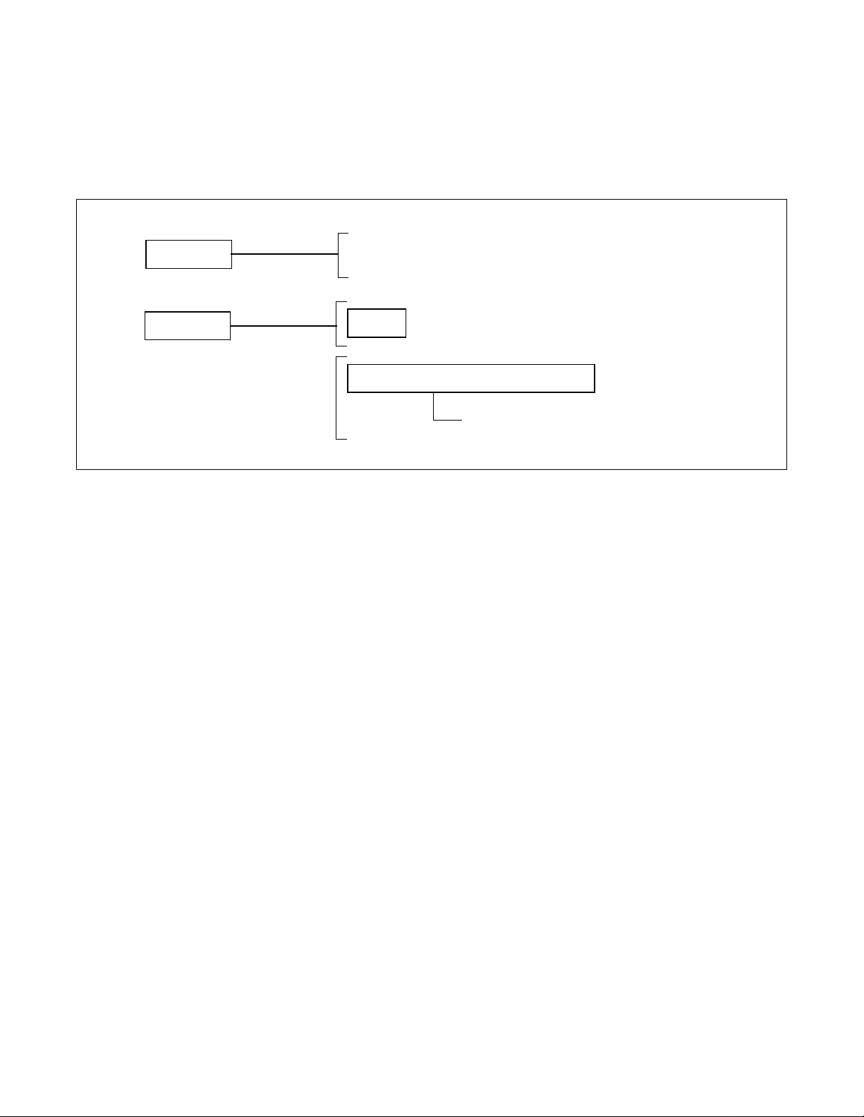
Table 1-1 Configuration of this Manual . . . . . . . . . . . . . . . . . . . . . . . . . . . . . . . . . . . . . . . . . . . . . . . . . . 1
Table 1-2 Related Reference Manuals . . . . . . . . . . . . . . . . . . . . . . . . . . . . . . . . . . . . . . . . . . . . . . . . . . 2
Table 2-1 CallCenterWorX-Enterprise (I) ACD Capacities . . . . . . . . . . . . . . . . . . . . . . . . . . . . . . . . . . . 9
Table 2-2 Interface Condition. . . . . . . . . . . . . . . . . . . . . . . . . . . . . . . . . . . . . . . . . . . . . . . . . . . . . . . . . 10
Table 3-1 Hardware and Software Upgrading Requirements . . . . . . . . . . . . . . . . . . . . . . . . . . . . . . . . 38
Table 4-1 List of ACD Circuit Cards. . . . . . . . . . . . . . . . . . . . . . . . . . . . . . . . . . . . . . . . . . . . . . . . . . . . 41
Table 5-1 CCV for ACD Calls Transfer (in case of Traffic Congestion) . . . . . . . . . . . . . . . . . . . . . . . . 183
Table 5-2 ACD SERVICE LIST . . . . . . . . . . . . . . . . . . . . . . . . . . . . . . . . . . . . . . . . . . . . . . . . . . . . . 196
Table 5-3 Call Distribution Algorithm - I. . . . . . . . . . . . . . . . . . . . . . . . . . . . . . . . . . . . . . . . . . . . . . . . 271
Table 5-4 Call Distribution Algorithm - II . . . . . . . . . . . . . . . . . . . . . . . . . . . . . . . . . . . . . . . . . . . . . . . 271
Table 5-5 Valid Logon ID/Position Combinations. . . . . . . . . . . . . . . . . . . . . . . . . . . . . . . . . . . . . . . . . 273
Table 7-1 NEAX2400 IMX Command List in Alphabetical Order. . . . . . . . . . . . . . . . . . . . . . . . . . . . . 333
Table 7-2 ACD Command List. . . . . . . . . . . . . . . . . . . . . . . . . . . . . . . . . . . . . . . . . . . . . . . . . . . . . . . 376
Table 7-3 Related Commands . . . . . . . . . . . . . . . . . . . . . . . . . . . . . . . . . . . . . . . . . . . . . . . . . . . . . . 377
Table 7-4 COND (Conditional Thresholds) . . . . . . . . . . . . . . . . . . . . . . . . . . . . . . . . . . . . . . . . . . . . . 384
Table 7-5 Programming Considerations . . . . . . . . . . . . . . . . . . . . . . . . . . . . . . . . . . . . . . . . . . . . . . . 393
Table 7-6 CCV Parameters . . . . . . . . . . . . . . . . . . . . . . . . . . . . . . . . . . . . . . . . . . . . . . . . . . . . . . . . . 397
Table 9-1 System Messages and Lamp Indications on the TOPU . . . . . . . . . . . . . . . . . . . . . . . . . . . 436
Table 9-2 System Messages for MIS. . . . . . . . . . . . . . . . . . . . . . . . . . . . . . . . . . . . . . . . . . . . . . . . . . 437
Table 9-3 Repairing Proce dure for TCP/IP Link Failure (Message “4-R ”) (1/2). . . . . . . . . . . . . . . . . . 450
Table 9-3 Repairing Proce dure for TCP/IP Link Failure (Message “4-R ”) (2/2). . . . . . . . . . . . . . . . . . 450
Table 9-4 Repairing Proce dure for TCP/IP Link Failure (Message “26-V”) . . . . . . . . . . . . . . . . . . . . . 450
Table B-1 Field Values for ACD Screens (1/8) . . . . . . . . . . . . . . . . . . . . . . . . . . . . . . . . . . . . . . . . . . 455
Table C-1 ACD Service List in Fusion Network . . . . . . . . . . . . . . . . . . . . . . . . . . . . . . . . . . . . . . . . . 463
NDA-24282 LIST OF TABLES
Page ix
Revision 1.0
Page 19

This page is for your notes.
LIST OF TABLES NDA-24282
Page x
Revision 1.0
Page 20

CHAPTER 1 INTRODUCTION
1. GENERAL
This manual describes the system outline and procedures for installation/installation tests, operations, maintenance and data assignment of Automatic Call Distribution (ACD) in the IMX System.
1.1 CONFIGURATION OF THIS MANUAL
The configuration of this manual is shown in Table 1-1.
Table 1-1 Configuration of this Manual
CHAPTER TITLE CONTENTS
2
GENERAL INFORMA TION This chapter explai ns the concept, func tion and conf iguration of
the NEAX2400 CallCenterWorX-Enterprise ACD System.
INSTALLATION This chapter explains the procedures of installation and or
3
installati on tests of the NEAX2400 CallCenter WorX-Enterprise
ACD System.
4
5
6
CIRCUIT CARDS This chapter explains the circuit cards and switch settings for
External ACD in the IMX System.
OFFICE DATA DESIGN This chapter explains office data assignment applicable to the
NEAX2400 CallCenterWorX-Enterprise ACD System.
ACD SERVICE FEATURES
FUNCTIONAL TEST
This chapter explains the test procedure of each ACD service
feature.
PROCEDURES
PBX AND ACD COMMAND
7
PROGRAMMING
This chapter explains the commands used in the NEAX2400
CallCenterWorX-En terprise ACD System. Sample
programming sheets that may be copied and used to help
config ure a syst em a re included.
SYSTEM OPERATIONS This chapter explains the operating methods of Agent/
8
Supervisory Posit ion. And explains t he restart pr oce ssing of the
NEAX2400 CallCenterWorX-Enterprise ACD System.
SYSTEM MAINTE NANCE This chapter explains the maintenance, diagn oses (according to
9
system messages), and fault repair of the NEAX2400
CallCenterWorX-En terprise ACD System.
APPEND IX A GLOSSARY This appe n d ix gives explanations of ACD-re lated terms.
APPENDIX B
FIELD VALUES FOR ACD
SCREENS
This appe n d ix gives descriptions of all data values entered into
MAT command screens when configuring and managing an
ACD syst em.
APPENDIX C
ACD SERVICE IN FUSION
NETWORK
This appe n d ix gives descriptions of the ACD service activated
between two fu s i o n node s through Fusion link.
NDA-24282 CHAPTER 1
Revision 1.0
Page 1
Page 21

INTRODUCTION
1.2 RELATED REFERENCE MANUALS
For maintenance to be performed on the NEAX2400 CallCenterWorX-Enterprise ACD System, there are
operations pertaining to ACD functions a nd those pertaining to the NEAX2400 IMX itself. Because this manual
explains only the operations pertaining to ACD functions, related reference manuals explaining the procedures
of the NEAX2400 IMX must be used with this manual when performing maintenance on the NEAX2400
CallCenterWorX-Enterprise ACD System as a whole.
IMX reference manuals and their relation with this manual are shown in Table 1-2.
Table 1-2 Related Reference Manuals
MANUAL NAME REL ATION TO THIS MANUAL
Installation Manual When performing installation/installation tests, use the manuals na med
in conjunction with Chapter 2, “General Information”, Chapter 3,
Circuit Card Manual
“Installation” and Chapter 4, “Switch Se tting of ACD Circuit Cards”
located in this manual
System Operations and Maintenance
Manual
Maintenance operations can be performed by referring to the manual
listed in addition to Chapter 8, “System Operations” and Chapter 9,
“System Maintenance” in this manual.
Office Data Specification Refer to the man u al lis t ed w h en programming office data other than for
the AC D. Chapter 7, “PBX and A CD Command Programming” include s
some information for commands used with the ACD System.
1.3 PRECAUTION ON USING THE ACD FEATURES
CAUTION:
The use of a monit oring, recording or liste ning devic e s to eave sdrop, monitor or record telephone
conversations or other sound activities, whether or not contemporaneous with its transmission, may be illegal
in certain circumstances under federal or state laws. Legal advice should be sought prior t o imp lementing any
practice that monitors or records any telephone conversation. Some federal and state laws require some form
of notification to all parties to the telephone conversation, such as using a beep tone or other notification
methods or require the consent of all parties to the telephone conversation, prior to monitoring or recording a
telephone conversa tion. Some of these laws incorporate strict penalties.
CHAPTER 1 NDA-24282
Page 2
Revision 1.0
Page 22

CHAPTER 2 GENERAL INFORMATION
1. GENERAL
This chapter provides the user with a basic working knowledge of the NEAX2400 CallCenterWorX-Enterprise
(ACD) System. It also explains how to use documents furnished with the NEAX2400 CallCenterWorXEnterprise (ACD) System.
The conte nts o f this chapter and how to foll o w the informa tion ar e as follows :
1.1 SYSTEM SPECIFICATIONS
The System Specifications section describes the NEAX2400 CallCenterWorX-Enterprise (ACD) System
equipment configura tion, fu nctions a nd specifi cations, i nterface conditions for external equipment, and other
related subjects.
Persons having little or no basic working knowledge of the NEAX2400 CallCenterWorX-Enterprise (ACD)
System (equipment configuration, component functions, etc.) should read and thoroughly understand this
chapter before proceeding.
1.2 GLOSSARY OF TERM S
The terms used throug hout the manual are li sted and described in Section 3, “Glo ssary of Terms” of this c hapter.
NDA-24282 CHAPTER 2
Page 3
Revision 1.0
Page 23
GENERAL INFORMATION
2. SYSTEM SPECIFICA T I ON S
2.1 GENERAL
This section descri be s the concept, functions and configuration of the ACD in the IMX System.
This chapter includes the following information:
• Functional Outline: Describes the outline of the ACD.
• System Confi guration: Describes the configur ation of the ACD.
• MIS: Describes the MIS functions.
• Interface between ACD and MIS: Describes the interface condition to be used with the ACD in the IMX
System and MIS.
• Equipment related to ACD: Describes the related equipment used with the ACD in the IMX System.
NEAX2400 IMX
CallCenterWorX - Enterprise
ACD System
Announcement
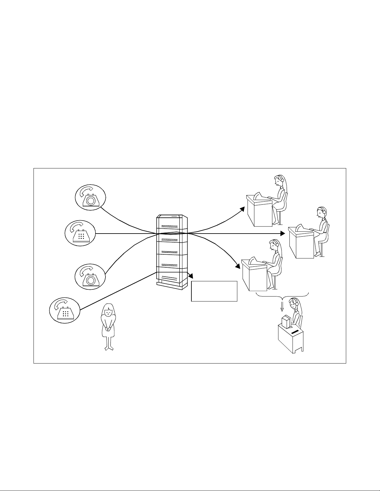
Figure 2-1 Functional Outline of NEAX2400 CallCenterWorX-Enterprise ACD System
CHAPTER 2 NDA-24282
Page 4
Revision 1.0
Machine
Supervisory
position
Page 24

GENERAL INFORMATION
2.2 FUNCTIONAL OUTLINE
Presently, telephone reception services are provided to a wide variety of businesses including mail orders and
travel rese rvatio ns. Howev er, as t he num ber of c usto mers i ncrea se, these services are o ften su bjected to co mplaints such as telephone c a lls not answere d for long periods of time, or the telephones being busy.
The agent positions receiving these calls also have problems which make their operators busy, such as calls being concentrated on specific positions.
To solve the problems of customers and telephone operators, the CallCenterWorX-Enterprise (ACD) system
provides a range of service features. The addition of the Management Information System (MIS) to the ACD
system saves excessive personnel expenses and communications costs based on calculations of the optimum
number of operators and trunks.
The NEAX2400 CallCenterWorX-Enterprise (ACD) System can connect large amount of incoming calls automatically to the groups composed of ACD agent positions . These calls are processed in the order of their arrival,
and distrib uted evenly among the ACD agent positions.
When all ag ent positions h an d lin g i nco ming calls ar e bu s y or t heir s pli t s have already finished the service, the
ACD can transmit various announcements to the calling customers.
The supervisor is able to supervise the agent positions. The supervisor can monitor the performance of each
agent and change the system administration style to optimize the personnel arrangement.
NDA-24282 CHAPTER 2
Page 5
Revision 1.0
Page 25
GENERAL INFORMATION
2.3 SYSTEM CONFIGURATION
The ACD system can be implemented in the internal Type configuration, with which the ACDP is built in the
CPU of the NEAX2400 IMX.
The configuration of the NEAX2400 CallCenterWorX-Enterprise (ACD) System is defined as follows.
Single CPU configuration (Figure 2-2)
External Type
Dual C PU co nf ig ur a t io n (F i gu r e 2-3)
Internal Ty p e
Built- in C PU
Provided with E xt er n al LAN
cable connected from the PBX
ACDP
MIS Interface Circuit
Ether: TCP/IP
CHAPTER 2 NDA-24282
Page 6
Revision 1.0
Page 26
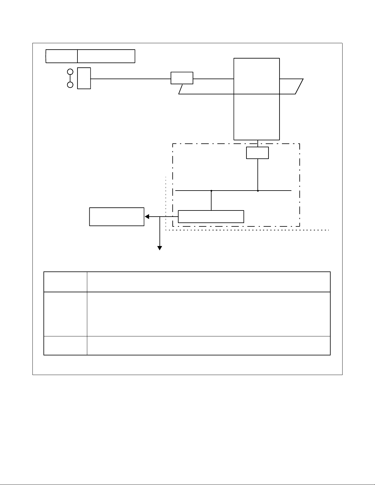
GENERAL INFORMATION
NEAX2400
IMX
Single Configurat ion
term
D
ELC
MIS ETHER (External LAN)
TSW
CPU
CPR
LPM
Externally inst alled equi pment
SYMBOL FUNCTION
CIRCUIT CARD
NAME
REMARKS
CPU Central Processing Unit (ACDP) RAM: Built-in Data Memory
ELC Electronic Line Circuit PA-16ELCJ
term
Digital Multifunction Telephone
D
MIS Management Information System
ETHER
Ethernet Controller Ethernet + TCP/IP protocol
management
Figure 2-2 Block Diagram of ACD System (Single CPU Configuration)
NDA-24282 CHAPTER 2
Page 7
Revision 1.0
Page 27

GENERAL INFORMATION
NEAX2400
IMX
D
Dual Con figurat ion
term
MIS
ELC
ETHER (External LAN)
TSW
CPU
CPR
LPM
Externally inst alled equip m ent
SYMBOL FUNCTION
CIRCUIT CARD
NAME
REMARKS
CPU Central Processing Unit (ACDP) RAM: Built-in Data Memory
ELC Electronic Line Circuit PA-16ELCJ
term
Digital Multifunction Telephone
D
MIS Manage men t In fo rmation System
ETHER
Ethernet Controller Ethernet + TCP/IP protocol
management
Figure 2-3 Block Diagram of ACD System (Dual CPU Configuration)
CHAPTER 2 NDA-24282
Page 8
Revision 1.0
Page 28

GENERAL INFORMATION
2.3.1 S YSTEM CAPACITY
CallCenterWorX-Enterprise (ACD) system capacity can be upgraded by installing the ACD Option Service
Software (standard) for extending ACD capacity.
For the procedure to link with the Optional Service Software, refer to Chapter 4 “System Startup” in the
Installation Manual.
Table 2-1 CallCenterWorX-Enterprise (I) ACD Capacities
25-1,000 Seats
System Components
Version (I4.01.00.000)
Analog Agent Access Codes 4,000 *
Announcement Routes 58
Call Active (simultaneous calls) 6,000
Call Control Vectors (20 steps each) 1,200
Holiday Schedules per Tenant 3
IVR Ports 400
Logon IDs (9 digits maximum) 7,000
Personal Pilot Numbers 4,000 *
Pilot Numbers 4,000 *
Priority Level 250
Splits 900
Splits per Agent 16
Station Calls 500
TCP/IP Clients 8
Tenants 10
Transfe r to PBX Numbers 1,200
Trunk Groups 255
Note:
*
Note:
Personal Pilots, Pilots, and Analog Access Codes cannot exceed 4,000.
Due to the amount of memory allo cated to the A CD database , use conse cutiv e numbering when poss ible to
gain the maximum number of pilot numbers, ACD myline, ACD line, IVR parts, and analog access codes
available.
NDA-24282 CHAPTER 2
Page 9
Revision 1.0
Page 29

GENERAL INFORMATION
2.4 MIS
The Management Information System (MIS) expands the benefits of the telephone reception services of the
ACD system by providing efficient administration.
The number of handled ACD calls, system capacity and functions of the MIS vary depending on whether it is
based on a Navigator MIS. The MIS calculates the traffic related to the ACD calls and issues reports. The basic
purpose of MIS is to provide statistical d at a to b e us e d in calc ulations of the number of agents required and the
amount of C.O. trunk traffic.
System administration can be optimized by the supervisor, by setting the average delay time response of the
trunk group or split between 20 and 40 seconds. If the del ay time is less than 20 seconds, agents become idle,
thus the number of agents can be reduced. When delay time is more than 40 seconds, the number of agents
should b e increa se d. (Note the number of agents is dependent on the customers.)
From the MIS, the supervis or can change t he office data re lated to the ACD, includ ing the C .O. call destination ,
overflow condition and the number of agents.
[Precautions for Use of Navigator MIS]
When using the Navigator MIS, please note the following points:
• If the customer uses the Navigator MIS on a 24-hour basis, be sure to install the Navigator MIS in an
air-conditioned room to ensure normal operation and preventing the hard disk from overheating.
• Be sure to perform shutdown procedure before powering off the MIS personal computer. If the power
is turned off without running the procedure, statistical data on the hard disk will be corrupted or
destroyed.
2.5 INTERFACE BET W E EN ACD AND MIS
Table 2-2 show s the interfa c e c ondition b e t ween the ACD in the IMX System and M I S .
Table 2-2 Interface Condition
CIRCUIT CARD INTERFACE CONDITION
Physical Interface ETHER
ETHER
Communication protocol TCP/IP
Data Transmission Speed 10 Mbps
2.6 EQUIPMENT RELATED TO ACD SYSTEM
2.6.1 AGENT POSITION
1. Function
This type of agent position is comprised of a t elephone, jack set and a headset. It is equipped wi th the ACD
functions as well as the multifunction telephone functions including the single-key speed dialing. It
operates off the 16ELCJ card.
CHAPTER 2 NDA-24282
Page 10
Revision 1.0
Page 30

2. Specifications
GENERAL INFORMATION
Dimensions
Cable Conductors 2-conductor (1 Pair)
Dista nce from PBX Less than 850m (2787 ft .)
3. Outer View
Figure 2-4 shows the outer view of D
term
D
Series III
D
D
term
term
Series I II
Series E
term
7
*
0
105 (H) mm × 205 (W) mm × 225 (D) mm
98.1 (H) mm × 177.0 (W) mm × 223.7 (D) mm
Series III Agent Position.
1
2
4
3
5
6
8
9
#
Figure 2-4 Outer View of D
NDA-24282 CHAPTER 2
term
Series III Agent Position
Page 11
Revision 1.0
Page 31

GENERAL INFORMATION
Figure 2-5 shows the outer view of D
term
D
Series E
term
Series E Agent Position.
.
.
.
.
.
.
.
.
.
.
.
.
.
.
.
.
1
4
G
H
I
5
J
K
L
7
P
Q
R
S
8
T
U
V
W
X
0
O
P
E
H
R
o
l
d
#
T
r
a
n
s
f
e
r
A
n
s
w
e
r
S
p
e
a
k
.
.
.
.
2
A
B
C
6
M
N
O
9
Y
Z
C
o
R
e
d
i
a
l
e
r
.
.
3
D
E
F
R
e
n
f
M
I
C
.
F
F
e
e
a
a
t
u
t
r
u
e
r
e
c
a
l
l
E
x
i
t
.
.
.
.
.
.
.
.
.
.
.
.
.
.
.
.
.
.
.
.
.
.
.
.
.
.
.
.
.
.
.
.
.
.
N
E
C
H
e
l
p
.
.
.
Figure 2-5 Over View of D
term
Series E Agent Position
CHAPTER 2 NDA-24282
Page 12
Revision 1.0
Page 32

GENERAL INFORMATION
2.6.2 SUPERVISORY PO SITION
1. Function
The supervisory position is equipped with the agent position functions and the display terminal. It is used
as the supervisor of splits to manage the ACD operations by overriding calls to agent positions, call monitoring, agent position status display, etc.
The supervisor position consists of an ACD agent position and a display with keyboard (MIS terminal).
Some supervisor positions are not equipped with the MIS terminal.
Note:
ACD Supervisory Position (D
term
)
Personal Computer/D ata
Termin al Equipm ent
1
2
4
3
5
6
7
8
9
*
0
#
Note
Distance between ACD Agent position and MIS terminal: Max.15m (49 feet)
Figure 2-6 Supervisory Positions
NDA-24282 CHAPTER 2
Page 13
Revision 1.0
Page 33

GENERAL INFORMATION
3. GLOSSARY OF TERMS
This section def i ne s A C D-related terms.
ACD Agent
ACD Agent
Split
Supervisory
ACD Agent
ACD Agent
Split
Supervisory
Position
Position
Group
Position
Position
Position
Group
Position
NEAX2400 IMX ACD System
ELC
ELC
ELC
ELC
ELC
ELC
Queue
Queue
COT
COT
COT
COT
COT
Trunk G r ou p
Trunk G r ou p
System
Supervisory
Printer
Position
MIS
ELC
ETHER
Figure 2-7 NEAX2400 CallCenterWorX-Enterprise ACD System Configuration
CHAPTER 2 NDA-24282
Page 14
Revision 1.0
ACDP
CPR
Page 34

GENERAL INFORMATION
• Trunk Group
A group, organized according to routes, of trunks which transmits calls incoming to or originated from the
ACD Sy st em.
• ACD Group (Tenant)
An ACD system can be divided into groups according to the user firms or departments. The ACD group is
the unit of such a division. Its configuration is as shown in Figure 2-8.
Note:
The following data must be assigned on an ACD tenant basis:
• Trunk Group
• ACD Monitored Number (Pilot Number)
• Split
• Announcement Equipment
• Transferring Destination (STN)
• Transferring Destination (TRK)
Split
1
Supervisory position
Split
n
ACD
Group
(Tenant)
(Tenant)
NEAX2400 IMX
Figure 2-8 ACD Group Configuration
NDA-24282 CHAPTER 2
ACD
Group
C.O.
Line
Page 15
Revision 1.0
Page 35

GENERAL INFORMATION
• Split
The unit of division o f an ACD group according to func tions. Ea ch split is compo sed of a q ueue to ho ld
incoming calls temporarily, agent positions to answer the incoming calls, and a group supervisory positio n.
• Queue
The queue is the area in which calls incoming to the ACD in the IMX System wait for handling. Each split
has multiple queues.
When all of the agent positions of a queue are busy, the calls assigned to that queue will wait. As agent
positions beco me idle, the c alls are distr ibuted t o the agent posi tions accor ding to f irst-in, f irst- out condition .
However, since queues are assigned different priority levels, the calls in higher-priority queues are
distributed before the calls in lower-priority queues.
•Overflow
An ACD call w aiting in a q ueue of a split that cannot be connected to an agent position assigned t o the queue
(overflow origination) once a predetermined period of time had elapsed, the call is sent to the queue of
another split (overflow destination) where it can wait for an agent position to become idle in both queues.
This allows the ACD call to be answered by the first available agent.
• Overflow Threshold
The period of time between the origination of an ACD call and its overflow.
• Inflow Threshold
Specific value defined by number of waiting calls in the overflow destination.
• ACD Agent Position
All agent positions belong to any ACD group and an ACD call is originated/picked up from the agent
position. Also, when Client/Server MIS system is used, ACD agent positions may have the client MIS.
• Group Supervisory Position
The position assigned the agent position supervisory functions, such as monitoring of agent positions and
assistance of agent posi tions , as well as the f unctions of an age nt posit ion. It may be equi pped with the MIS
Terminal (DTE) which can display the status of the ACD subsystem.
• Agent
The operator using an agent position to handle calls via the ACD system. Every agent can be assigned an
ID code to logon to the CallCenterWorX-Enterprise (ACD) system. For the purpose of effective use, the
agent can u se to connect the client MIS.
• Group Supervisor
This is the manager who uses a supervisory position to assist agent positions, monitor them, supervi s e thei r
status using the MIS term inal, and c hange the syst em configu rati on of an ACD group. Ever y supervisor can
be assigned an ID code.
• MIS Terminal (DTE)
This is the MIS Data Terminal Equipment used to display the ACD status and/or change the system configuration.
CHAPTER 2 NDA-24282
Page 16
Revision 1.0
Page 36

GENERAL INFORMATION
Supervisory
Position
Agent
Position 1
Agent
Position2
0:00
Night Mode
Unavailable Available
“Log ON/OFF” key pressed
Unavailable
“Log ON/OFF” key pressed
9:00 10:00 11:00 12:00 13:00 14:00 15:00 16:00 17:00 18:00 24:00
Night ModeDay Mode
“Night” key pressed
key pressed
Available
Break
“Break”
Break
“Break”
key pressed
Break
“Break”
key pressed
Break
“Break”
key pressed
“Log ON/OFF” key pressed
“Night” key pressed
Unavailable
Unavailable
“Log ON/OFF” key pressed
Available
(Ready Mode)
Figure 2-9 Concept of Operation Mode
• Day/Night Mode
The day and night mode determine the destination of incoming ACD calls on a per-split basis. Set the day
mode when starting the ACD call reception service, and set the night mode to end the ACD call reception
service in the evening or before the agent leaves position.
• Ready Mode
This is the status of an ACD position (including group or system supervisory position) after starting the
reception se rv i ce. In this s tate, the position can answer ACD calls.
• Work Mode
This is the state of an ACD position (including supervisory position) in which it restricts the termination of
incoming ACD calls. The agent ma y then perfor m nonverbal tasks, s uch as t he crea tion of a bu siness slip.
The Work mode can be set either automatically at the end of conversation with an incoming call (Automatic
After Call Work mode) or manually by pressing the “Work” key as needed.
NDA-24282 CHAPTER 2
Page 17
Revision 1.0
Page 37

GENERAL INFORMATION
• Break Mode
This is the state of an ACD position (including supervisory position), which is activated by the agent
pressing the “BREAK” k ey t o disa llo w the termin ation of inc oming ACD calls before the a gent temporari ly
leaves the position.
• ACD Trunk in a Fusion Network
ACD trunks can be accommodated in the multiple nodes within the Fusion network and via the trunk in the
remote node, ACD calls can be originated or picked up from the agent accommodated in the node that provides ACDP.
• Agent Anywhere
With this function, ACD agent positions can be installed in multiple nodes of a Fusion Network, and ACD
calls can be distributed to ACD agents in the remote node. Those agent positions are controlled by one
ACDP in a Fusion Network.
• Expanding ACD capacity
With the ACD Option Service Software, the built-in ACDP capacity will be extended and more than 1000
agent pos i tio n s can be installed.
• Split of Supervisors (see Multiple Supervisor Groups (Splits) - A CD [M-79A])
Split formed by mul tipl e supervi sors. It is benef icial whe n more th an one supervi sor ser ves a sp lit of agents .
CHAPTER 2 NDA-24282
Page 18
Revision 1.0
Page 38

CHAPTER 3 INSTALLATION
1. GENERAL
This chapter desc ribes the inst allation and t est procedure s for the NEAX2400 Call CenterWorX-Enter prise ACD
System.
The installation of the ACD in the IMX system is completed by the installing the MIS, MIS interface, and terminal equipment such as agent positions and supervisory positions.
Because the inst allation procedures require d for the NEAX 2400 IMX are the same as for the business system,
this manual describes only the terminal equipment related to the MIS and ACD positions. For information on
installation procedures related to the NEAX2400 IMX, refer to the NEAX2400 IMX Installation Manual.
2. PRECAUTIONS
2.1 ESSENTIAL/CRITICAL INFORMATION
To prevent accidents or equipment damage from occurring while installation is being performed, each
NEAX2400 IMX manual provides “WARNING”, “CAUTION”, and “Note” indications to draw the technician’s atten tio n t o s p ecific matters.
1. Meaning
WARNI NG: P ersonal injury may result if the warning is not heeded.
CAUTION
Note:
Indicates an item which requires special attention.
2. Locations of Indicators
WARNI NG
of the procedures on the page.
: Damage to the equipment and/or the system may result if the caution is not heeded.
and CAUT IO N indica tions are locat ed at the top of the page. Descriptions are included as part
ATTENTION
Contents
Static Sensitive
Handling
Precautions Required
Figure 3-1 Static Caution Indication
NDA-24282 CHAPTER 3
Page 19
Revision 1.0
Page 39

INSTALLATION
This manual provides Static Caution indicators (see Figure 3-1) on page where work involving static-sensitive
components is described.
The 3M Model 8012 Portable Field Service Kit, shown in Figure 3-2 is recommended as an effective countermeasure against static electricity. The kit is available from NEC.
Wrist Strap
Place the Circuit Card
on a Conductive
sheet.
Connect ground wire to the Earth
terminal of the M odule Group
Figure 3-2 3M Mo del 8012 Portable Field Service Kit
CHAPTER 3 NDA-24282
Page 20
Revision 1.0
Page 40

INSTALLATION
3. INSTALLATION PROCEDURES
3.1 PERIPHERAL EQUIPMENT INSTALLATION
This section explains the procedures to instal l periphera l equipment f or the ACD in the IMX system (Agent positions, MIS terminals, etc.).
The reference NAPs for the peripheral equipment are indicated in Figure 3-3.
NAP-200-101
NAP-200-102
NAP-200-103
NAP-200-104
NAP-200-105
MDF
NEAX2400 IMX
ACD Agent Position
ACD Supervisory Position
MIS
Emergency Recorder
Announcement Machine
NAP-200-106
IVR/Host
Figure 3-3 Peripheral Equipment Installation Procedures
NDA-24282 CHAPTER 3
Page 21
Revision 1.0
Page 41
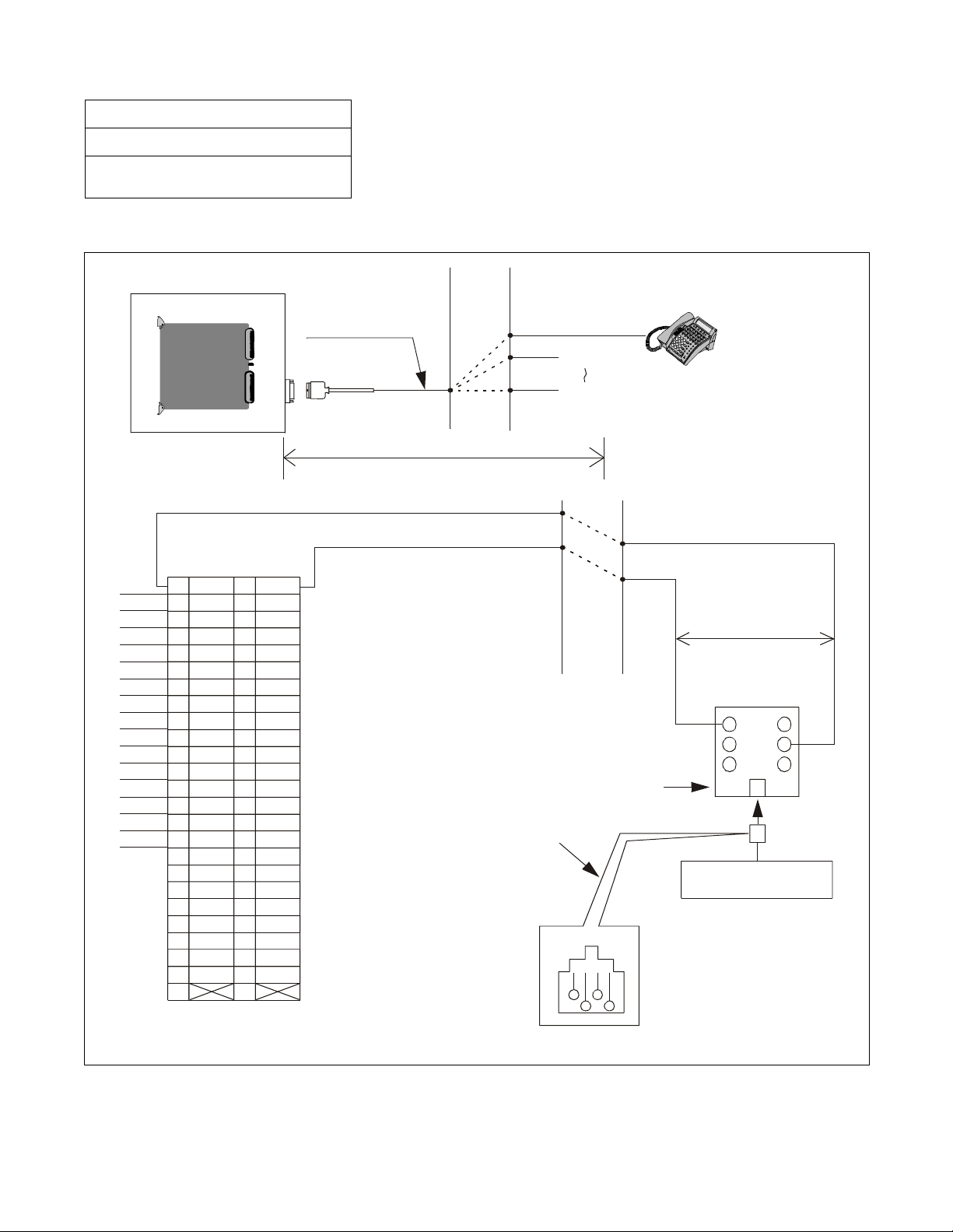
INSTALLATION
NAP-200-101
Sheet 1/3
Installati on of ACD Agent Posi tion
Figure 3-4 shows the cable connection between the Agent Position and the NEAX2400 IMX.
MDF
PIM
Installa tio n C ab le
(D
term
term
D
No.0
Series II I/Se r ie s E)
No.0
No.1
No.2
No.3
No.4
No.5
No.6
No.7
No.8
No.9
No.10
No.11
No.12
No.13
No.14
No.15
Note 2:
PA-16ELCJ
PA-16ELCJ
B0
B1
B2
B3
B4
B5
B6
B7
B8
B9
B10
B11
B12
B13
B14
B15
1
2
3
4
5
6
7
8
9
10
11
12
13
14
15
16
17
18
19
20
21
22
23
24
25
26
27
28
29
30
31
32
33
34
35
36
37
38
39
40
41
42
43
44
45
46
47
48
49
50
16ELC Camp
Connector Leads (example)
LT
A0
A1
A2
A3
A4
A5
A6
A7
A8
A9
A10
A11
A12
A13
A14
A15
Max. 850m (0.5φ)
Note 1:
Connector leads (A0 and B0)
may be connected with Modular Rosette.
Modular Jack
No.1
No.15
MDF
Modular Rosette
123
4
A0 B0
For more details of connector lead accommodation, see “Circ uit Card Manual”.
Note 1
1
3
Agent Position
2
4
Figure 3-4 Connection of ACD Agent Position
CHAPTER 3 NDA-24282
Page 22
Revision 1.0
Page 42

INSTALLATION
NAP-200-101
Sheet 2/3
Installati on of ACD Agent Posi tion
• Attach the pro vided ke y pa d/labe ls to ident ify the names of the k eys. For the funct ion ke y data assignment s,
refer to the AKYD command in Chapter 7.
term
(1) D
Series III
CW AUTO/MAN ASSIST EMER TRKTRBL RECALL
ACD CALL LINE FNC HAND/HEAD MIC SPKR
213
546
879
0
#
RLS
BREAK
LOGON
TALLY
*
HOLD XFR CONF WORK
Figure 3-5 Key Pads on ACD Agent Position Keyboard (D
term
Series III)
NDA-24282 CHAPTER 3
Page 23
Revision 1.0
Page 43

INSTALLATION
NAP-200-101
Sheet 3/3
Installati on of ACD Agent Posi tion
term
(2) D
Series E
CW
FUNC HAND/HEAD MIC SPKR
1
456
7
ASSIST EMERAUTO/MAN
ACDCALL LINETRKTRBL RECALL
2
3
89
RLS
BREAK
LOGON
0#
TALLY
WORKCONFXFRHOLD
FLEX KEY
Figure 3-6 Key Pads on ACD Agent Position Keyboard ( D
CHAPTER 3 NDA-24282
Page 24
Revision 1.0
term
Series E)
Page 44

NAP-200-102
Sheet 1/3
Installati on of ACD Supervisory Posi tion
Figure 3-7 shows the cable connection between the Supervisory Position and the NEAX2400 IMX.
INSTALLATION
No.0
No.1
No.2
No.3
No.4
No.5
No.6
No.7
No.8
No.9
No.10
No.11
No.12
No.13
No.14
No.15
Note 2:
PIM
PA-16ELCJ
PA-16ELCJ
26
27
28
29
30
31
32
33
34
35
36
37
38
39
40
41
42
43
44
45
46
47
48
49
50
16ELC Camp
Connector Leads (example)
B0
B1
B2
B3
B4
B5
B6
B7
B8
B9
B10
B11
B12
B13
B14
B15
1
2
3
4
5
6
7
8
9
10
11
12
13
14
15
16
17
18
19
20
21
22
23
24
25
LT
A0
A1
A2
A3
A4
A5
A6
A7
A8
A9
A10
A11
A12
A13
A14
A15
Install ation Cable
Max. 850m (0.5 f )
MDF
Note 1:
Modular Jack
term
D
term
(D
Series III/Seri es E)
No.1
No.15
MDF
Connector leads (A0,
B0) may be connected
with Modular Rosette.
Modular Rosette
123
4
No. 0
A0 B0
Supervisory Position
For more details of connector lead accommodation, see “Circuit Card Manual”.
Note 1
1
3
2
4
Figure 3-7 Connection of ACD Supervisory Position
NDA-24282 CHAPTER 3
Page 25
Revision 1.0
Page 45

INSTALLATION
NAP-200-102
Sheet 2/3
Installation of ACD Supervisory Position
• Attach the pro vided ke y pa d/labe ls to ident ify the names of the k eys. For the funct ion ke y data assignment s,
refer to the AKYD command in Chapter 7.
term
(1) D
Series III
CW AUTO/MAN TRKTRBL RECALL
ACD CALL LINE FNC HAND/HEAD MIC SPKR
MON/BARGE
213
546
879
0
NIGHT
RLS
BREAK
LOGON
#
TALLY
*
HOLD XFR CONF WORK
Figure 3-8 Key Pads on Supervisory Position Keyboard (D
CHAPTER 3 NDA-24282
Page 26
Revision 1.0
term
Series III)
Page 46

NAP-200-102
Sheet 3/3
Installation of ACD Supervisory Position
term
(2) D
Series E
INSTALLATION
CW
AUTO/MAN
TRKTRBL RECALL
FNC HAND/HEAD MIC SPKR
1
4
7
MON/BARGE
ACDCALL LINE
2
3
56
89
0#
XFRHOLD
BREAK
NIGHT
LOGON
RLS
CONF
TAL LY
WORK
FLEX KEY
Figure 3-9 Key Pads on Supervisory Position Keyboard (D
NDA-24282 CHAPTER 3
term
Series E)
Page 27
Revision 1.0
Page 47

INSTALLATION
NAP-200-103
Sheet 1/1
Installation of MIS
Figure 3-10 shows the cable connection between the MIS and the NEAX2400 IMX.
LPM
BASEU
00 01 02 03 04 05 06 07 08 09 10 11
00 01 02 03 04 05 06 07 08 09 10 11
PH-PC40 (EMA)
PH-IO24 (IOC)
10BASE-T (Straight)
12 13 14 15 16 17 18 19 20 21 22 23
LANI (PZ-PC19)
HUB
Note:
When the client MIS and I VR /H o st are installed in a system together, LAN network for these terminals
should be separated by the router.
Figure 3-10 Cable Connection between MIS and PBX
CHAPTER 3 NDA-24282
Page 28
Revision 1.0
MIS
Page 48

NAP-200-104
Sheet 1/1
Insta l lation of Eme rgency Recorder
Figures 3-11 and 3- 12 show connection for an Emergency Recorder.
INSTALLATION
16COT
No.0 circuit
R0
T0
16COT
No.0 circuit
No.1 circuit
G
R0
T0
M
(T1)
-48V RPT0
FUSE
Power Receiving Terminal
MDF
A
B
G
-48V
AC
Emergency
Recorder
Speech Wires
Starting Wire
Figure 3-11 Conn ection of Emergency Recorder
(When Emergency Recorder Has Starti ng Terminal)
Speech Wires
Power Relay
MDF
A
B
Note
AC
Receptacle
Emergency
Recorder
AC
No.1 circuit
G
M
(T1)
RPT0
Power Receiving
Terminal
G
-48V
Note:
Starting Wire
If a power relay is used, select an optimum relay by
confirming the amplifiers current drain.
Figure 3-12 Conn ection of Emergency Recorder
(When Emergency Recorder Does No t Have Starting Terminal)
NDA-24282 CHAPTER 3
Page 29
Revision 1.0
Page 49

INSTALLATION
NAP-200-105
Sheet 1/1
Installat i on of A nnou ncement Machine
The standard announcement machine a vailable is PA-4DATA or PA-4DATB (4DAT: 4 Digita l Announce ment
Trunk) card. The 4DAT can be used by simply inserting it in the universal slot of PIM.
If a non-standard a nnouncement machine is used, the conne ction method and the announcement tr unk to be used
as interface vary depending on the machine.
An example of this connection is shown in Figure 3-13.
MDF
16 COT
No.0 circuit
No.1 circuit
G
R0
T0
R1
M
(T1)
–48V RPT0
Fuse
Power Receiving
Terminal
OA
OB
G
OC
(RT)
Figure 3-13 Connection of Announcement Machine
Announcement
Machine
–48 G
CHAPTER 3 NDA-24282
Page 30
Revision 1.0
Page 50

INSTALLATION
NAP-200-106
Sheet 1/1
Installation of IVR/Host
Figure 3-14 shows the system configuration when IVR/Host is installed.
For more details of IVR ca ble conne ction, refer to Figure 3- 15 and for the Host connection, refer to Figure 3-16.
E
L
C
term
D
(ACD Positions)
L
C
IVR/Host
Router
HUB
L
A
N
L
A
N
PBX
Note
MIS
Note:
When the client MIS and IVR/Host are installed in a system together, LAN network direct l y co nn ec ted
with these terminals should be separated by the router.
Figure 3-14 System Configuration (when IVR/Host is installed)
NDA-24282 CHAPTER 3
Page 31
Revision 1.0
Page 51

INSTALLATION
Figure 3-15 shows the cable connection between Host and the PBX.
HUB PKG
PIM
10BASE-T
LPM
(Straight)
10BASE-T
(Straight)
LANI
LANI
Note:
BASEU
10BASE-T (Straight)
When the client MIS and IVR/Host are installed in a system together, LAN network directly connected
with these terminals should be separated by the router.
Figure 3-15 Connection of Host
CHAPTER 3 NDA-24282
Page 32
Revision 1.0
Page 52

Figure 3-16 shows the cable connection between IVR and the PBX.
INSTALLATION
Note:
PIM
Installation cable
16LC
A0
B0
A1
B1
~
A15
B15
MDF
Note
Connector leads (A0, B0) may be connected differently.
Figure 3-16 Conn ection of IVR
L2
L1
Rosette
L2
L1
IVR
NDA-24282 CHAPTER 3
Page 33
Revision 1.0
Page 53

INSTALLATION
4. SYSTEM ST A RT-UP PRO C E DURE FOR ADDING ACD FEATURES
4.1 ACD SOFTWARE INSTALLATION
This section explains the installation procedure for adding the Built-in ACDP software to the PBX in on-line
operation. For more de tail ed inf ormation about s ta rt-up procedure s b efore the ACD a pplication soft ware install ,
see the “Installation Manual”.
[Operation Procedure]
a. Basic Operating Procedure
STEP 1 : By using MEM_HDD command, save all data to both HDDs.
STEP 2 : Insert the Built-in ACDP software FD into the HDD of the PBX.
Note 1:
When ACD service is used in a Fusion Network and when “ACD Trunk in a FCCS Network” is used:
Install the software int o t he node that accommodates the
When “AGENT ANYWHERE” is used:
Install the software into one node only. In this case, the node with the most ACD agent po sit i o n s is recommended to prevent network traffic congestion. The node that uses the ACDP is most re commended according to the service condition Item 3 described in “Agent Anywhere - ACD” in Chapter 5.
STEP 3 : Install the Configuration Software to all nodes.
Note 2:
This software is used to define the CallCenterWorX-Enterprise (ACD) system capacity (50, 200, 500, 900,
or 2000 Agent Positions).
STEP 4 : Ini tialize the system (pe rform IPL, DM load ing).
PROGRAM=“LOAD”
SYSTEM DATA=“LOAD”
ACDP
Note 2
.
CHAPTER 3 NDA-24282
Page 34
Revision 1.0
Page 54

INSTALLATION
b. When Installing ACD Trunk into Multiple Fusion Nodes (Software installation when the ACD trunk is in-
stalled at Fusion Nodes.)
(1) At the node that uses the ACDP, the A CD soft ware (Built-in ACDP software) and ACD Optio n Soft-
ware installation is necessary.
(2) At the node that accom m odate s th e ACD trunk, only ACD Option Software installation is necessary.
Do not install the ACD software.
(3) Initialize the node that uses the ACDP after the software installation.
c. When Installing ACD Agent Position into Multiple Fusion Nodes (For PBX Software Series 7300 or later)
(1) At the node that uses the ACDP, the ACD software (Built-in ACDP software) and the basic ACD
Option Software, installation is necessary.
(2) At the node that ac c ommodates the ACD trunk, ACD agent position, the basic ACD Option Service
Software must be installed.
(3) Initialize the node that uses the ACDP after the software installation.
d. When Installing ACDP into Multiple Fusion Nodes (For PBX Software Series 7400 or later)
(1) At the node that uses the ACDP, the A CD soft ware (Built-in ACDP software) and ACD Optio n Soft-
ware installation is necessary.
(2) At the node that accom m odate s th e ACD trunk, only ACD Option Software installation is necessary.
Do not install the ACD software.
(3) Initialize the node that uses the ACDP after the initialization of the other nodes (non -ACDP nodes).
NDA-24282 CHAPTER 3
Page 35
Revision 1.0
Page 55

INSTALLATION
4.2 BASIC DATA ASSIGNMENT FOR START-UP
STEP 1 : Change the system data written in DM.
ASYD SYS1
INDEX2 - b0=1 (ACDP mounted)
INDEX31 - b0~b3: CM mounting capacity
Assign Normally “06”.
INDEX79 - b6=0 (ACD service is effective)
INDEX207 - b0=1 (ACDP in system0 is used)
b1: ACDP in system1
0/1=Not used/Used
INDEX241 - b2=1 (call event process)
Note 1
Note 1
Note 1
Note 1:
When the A CD serv ice is ac tivate d via FCCS, this dat a must be set to all node s providing ACD service (Not
just the node accommodating the ACDP).
STEP 2 : Assign the system data written in LDM as shown below.
ASYDL SYS1
INDEX512: FPC of the self-node
INDEX513: 01 Hex (LDM usage)
INDEX515~518 b0~b7: IP address (Hex) for PBX over external LAN
INDEX519~522 b0~b7: Subnet Mask (Hex) for PBX over external LAN
INDEX523~526 b0~b7: Default Gateway Address for External LAN
(This data is required when the Host is connected via gateway)
INDEX864 - b0=1 (Built-in ACDP is provided)
INDEX864 b1: Output the system message (4-R) when TCP-IP is normally disconnected.
0/1 = Effective/Ineffective
b2: 0/1 = “Agent Anywhere” Out of Service/In Service
b3: 0/1 = Multiple ACDPs Not Available/Available
INDEX865: FPC of Node Providing IP.
INDEX866: FPC of Node Providing ACDP.
Note 2:
If the MA T or SMDR has been connecte d with e xt ernal LAN already, this d ata assignmen t is not neces sary.
STEP 3 : Assign the System data written in NDM.
This data is necessary when using “AGENT ANYWHERE” (Available since the PBX software
Series 7300.)
ASYDN SYS1
INDEX514- NDM usage
INDEX533- FPC of the node that provides VNDM
Note 2
Note 2
Note 2
Note 3
STEP 4 : Check the station-to-station connection and confirm no fault status occurs or system messages
are output (such as cable connection fault, LCD display fault, memory alarm fault, abnormal
interrupt, et c.).
STEP 5 : Program the ACD office data. Also, program the Fusion data to make ACD service effective
through Fusion network, if necessary. Refer to Chapter 5, “Office Dat a Design”.
STEP 6 : Save the DM, ACD data memory into the HDD by using MEM_HDD.
CHAPTER 3 NDA-24282
Page 36
Revision 1.0
Page 56

INSTALLATION
5. UPGRADING ACD SYSTEM FROM NEAX2400 ICS TO NEAX2400 IMX
Figure 3-17 and Table 3-1 show the requiremen t s w h en u p grading the Call Ce n ter W orX-Enerprise (ACD) sys-
tem from NEAX2400 ICS to 2400 IMX.
5.1 HARDWARE AND SOFTWARE REQUIREMENTS
Note 1:
PBX
[1] [2]
CPU
DM
ACDP
ACD DM
[4]
Router [9]
LAN
MAT
[3]
IVR/Host
[10]
[5], [6], [7], [8] are not necessary for the ACD without MIS.
Client MIS
[8]
Server MIS
[5]
[6]
[7]
MIS DB
(See Ta ble 3-1.)
Note 2:
[10] is not necessary for the ACD without IVR/Host.
Figure 3-17 Hardware and Software Upgrading Requirements
NDA-24282 CHAPTER 3
Page 37
Revision 1.0
Page 57

INSTALLATION
Table 3-1 Hardware and Software Upgrading Requirements
No.
[1]
[2]
[3]
[4]
[5], [6]
[7]
[8]
Upgrading Hardware or
Software
Generic Software
• Basic software
• Standa rd Service softwa re
• Optional software
All types of system PBX software Releas e 3 or later
NEAX2400 ICS
(before upgrading)
NEAX2400 IMX
(after upgrading)
• Basic software (#1~#11)
• Internal MAT software
(#1~#2)
• TCP/IP software
ACD software SC-2242 PRG-E or
Built-in ACDP software
SC-2243 PRG-F
MAT
IBMPC/AT Windows
Hardware and Software
ACD Data Memory PBX software Release 2 or
Release 3
Built-in type
Necessary t o be reprogrammed
via [3]
Server
MIS
Hardware and
Software
Data base
Nav igator MIS (IBMPC/AT) Navig ato r MIS (I BMPC/AT)
For NEAX2400 IMX system
Nav igator MIS (IBMPC/AT) Navig ato r MIS (I BMPC/AT)
(Config., static data,
etc.)
Client MIS terminal Software Navigator MIS (IBMPC/AT) (a) Remote MIS terminal
MIS terminal for Navigator
MIS (IBMPC/AT)
(b) Client MIS terminal
Navigator MIS client for
NEAX2400 IMX system
[9] R outer – Router
IVR/Ho st Hard w are and Soft ware
[10]
Note:
Necessar y when IVR/
Host is added only.
CHAPTER 3 NDA-24282
Page 38
Revision 1.0
Page 58

5.2 UPGRADING PROCEDURE
INSTALLATION
STEP 1 : Print out the existent data in the MIS terminal or save the data as the text file.
Note 4
STEP 2 : List up the office data related to the current ACDP.
STEP 3 : Shutdown MIS operation following the appropriate procedure.
Note 4
STEP 4 : Make busy the CPU (ACDP) card (CP53/CP54) and disconnect all cables connected to cards
related to ACD.
STEP 5 : Upgrade the PBX hardware following the Upgrade Manual for the PBX.
STEP 6 : Install the software below to upgrade the PBX software. Refer to Chapter 3, Section 4.1, “ACD
Software In stallation”.
• An assortment of software for NEAX2400 IMX
• Built-in ACDP soft wa re
• System Configuration Software containing ACD Options
Note 1
Note 2
STEP 7 : Program the following ACD commands data again.
ACDTN/ACDSPL/ACDLOG/ACDPSN/ACDCCV/ACDPLT/ACDTG/ACDANA/ACDIVR/
ACDHS/ACDHC/ACDWS
STEP 8 : Start up the Navigator MIS for IBMPC/AT.
Note 3
• Standard MIS hardware and software
• MIS terminal hardware and software
STEP 9 : Start up the IVR/Host.
• IVR/Host hardware and software
• Related Equipment for LAN
STEP 10 : Perform the installation test.
Note 1:
When ACD service is used in a Fusion Network, and when “ACD Trunk in aFusion Network” is used:
Install the software int o t he node that accommodates the ACDP.
When “AGENT ANYWHERE” is used:
Install the software into one node only. In this case, the node with the most ACD agent positions is
recommended to prevent networ k traffic congestion. The n ode that uses the ACDP is mos t recommended
according to the service condition Item 3 described in “Agent Anywhere - ACD” in Chapter 5.
Note 2:
Note 3:
Note 4:
When ACD features are activated in Fusion network, this software is installed in all nodes.
This procedure is not necessary for the ACD without MIS.
Details fo r s ta rt -up p ro c edure are decided by the IVR/Hos t f e ature spec ifications.
This procedure is not necessary when IVR/Host is not used.
Note 4
NDA-24282 CHAPTER 3
Page 39
Revision 1.0
Page 59

This page is for your notes.
CHAPTER 3 NDA-24282
Page 40
Revision 1.0
Page 60

CHAPTER 4 SWITCH SETTING OF ACD CIRCUIT CARDS
1. GENERAL
This chapter ex plains the circui t cards related to the NE AX2400 CallC enterWorX -Enterprise (ACD ) System
which are shown in Table 4-1.
Table 4-1 List of ACD Circuit Cards
SYMBOL CIRCUIT CARD
MOUNTING
MODULE
REMARKS
CPU PA-CP53 PIMU For circuit card type
EAPI PH-PC22/PH-PC27 LPRJ-A
ALMC PA-AL16 APM For module type
APINT PH-PC21 LPRJ-A
COPY PA-PC56-A APM
CPU PA-CP54 APM
CRAM PA-ME34 APM
IOC PA-IO02-A APM
PBI PH-BS16 APM
SPGT PA-GT17 MISCME For MISCME type
ELC PA-16ELCDD PIMU Common
16ELC PA-16ELCH PIMU Common
16ELC PA-16ELCJ PIMU Common
4DAT PA-4DATA PIMU Common
DAT PA-4DATB PIMU Common
4DTL PA-4DTLA PIMU Common
ETHER PA-CC98 APM/PIMU Module/Package
MBB PA-GT16 AP M Module
NDA-24282 CHAPTER 4
Page 41
Revision 1.0
Page 61

SWITCH SETTING OF ACD CIRCUIT CARDS
2. EXPLANATION OF ACD CIRCUIT CARDS
This section ex pl ai n s each of the ACD circuit cards rega rding the following items.
1. Function
Explanations are given about the functional outline and the purpose of each circui t ca r d.
2. Mounting Location/Condition
The mounting location of each circuit card is illustrated with the mounting module name, slot number, etc.
Any conditions pertaining to mounting are also denoted.
3. Face Layout of Lamps, Switches, and Connectors
The locations of the lamps, switches, and connectors provided on each circuit card are illustrated by a face
layout.
4. Lamp Indications
Lamps equipped on each circuit card, their names, colors, and indication states are tabulated.
5. Switch Setting
Switches equipped on each circuit card, their names, switch numbers, setting and its meaning, standar d set-
ting, etc. are tabulated.
6. External Interface
If the lead outputs of the circuit card are provided by an LT connector, the relation between the mounting
slots and the LT connector is illustra ted b y an LT Connector Lead F ace Layout. Also, i f the le ad output s are
provided b y other tha n an LT connector or the lead outputs a re pro vid ed by the c ircuit c ard fr ont connect or,
the connector lead accommodations and the connecting routes are illustrated.
A SWITCH SETTING SHEET showing module name, slot number, switch name, switch shape, e tc. is provided
at the end of the explanation of each circuit card.
CHAPTER 4 NDA-24282
Page 42
Revision 1.0
Page 62

PA-CP53 (CPU)
1. Function
This circuit card is the CPU card (Central Proc essing Unit) which controls the A CD Circuit Card T ype Sys-
tem. Using V60 microprocessor (32 bits), this CPU card provides programs and data memory. The card is
equipped with EPROM of 2 MB and SRAM of 1MB, respectively.
PA-CP53 (CPU)
ACDP
GATE
I/O LOCAL BUS
RS-232C (Non-protocol)
ACD-MIS
LPRJ-A
ACD in IMX system (Circuit Card Type)
Position within the system
EAPI
SYSTEM
CPU
NDA-24282 CHAPTER 4
Page 43
Revision 1.0
Page 63

PA-CP53 (CPU)
2. Mounting Location/Condition
The mounting locations of this circuit card and the conditions related to mounting are shown below.
(a) When this circuit card is mounted in PIMA
Mounting Module PIMU
00 01 02 03 04 05 06 07 08 09 10 11 12 13 14 15 16 17 18 19 20 21 22 23
Note: ●
(b) When this circuit card is mounted in PIMB
00 01 02 03 04 05 06 07 08 09 10 11 12 13 14 15 16 17 18 19 20 21 22 23
Note: ●
indicates the mounting locations of this circuit card.
Moun tin g Module PIMB
indicates the mounting locations of this circuit card.
CHAPTER 4 NDA-24282
Page 44
Revision 1.0
Page 64

3. Face Layout of Lamps, Switches, and Connectors
The face layout of lamps, switches, and connectors of this circuit card is shown below.
PA-CP53 (CPU)
4. Lamp Indications
SW1
SW0 SW2
CPU OPE
MBR
CLKA
COPA
LANA
DMWE
RESET
SENSE
The contents of lamp indications of this circuit card are shown in the table below.
LAMP NAME COLOR STATE
CPU OPE Green Remains lit while this circuit card is operating.
CLKA Red
Lights when a mic roprocesso r o perating clock failure has oc curred in this circuit
card.
COPA Red Lights when a C-level infinite loop has occurred.
LANA Yellow
Lights when a major failure has occurred in PA-CC98 card or when this circuit
card is not connect ed w ith PA-CC98 card.
Note
DMWE Green Remains lit when the data memory in this circuit card is in write enable state.
Note:
When this circuit is used only as ACDP, PA-CC98 card is not used and thus this card is operating normally
even if this lamp is lighting.
NDA-24282 CHAPTER 4
Revision 1.0
Page 45
Page 65

PA-CP53 (CPU)
5. Switch Settings
Standard settings of various switches on this circuit card are shown in the table below.
SWITCH
NAME
SWITCH
NO.
SETTING
STANDARD
SETTING
MEANING
UP Circuit card make busy request.
MBR
DOWN Circuit card make busy request cancel
RESET PUSH S ta rt i ng of reset of this ci rc u it card
5 × On line (Normal Operation)
SENSE
D
Clearing the data memory area at the time of
initialization
1OFF× Fixed
2OFF× Fixed
3OFF× Fixed
4OFF× Fixed
SW0
5OFF× Fixed
6OFF× Fixed
7OFF× Fixed
8ON× Fixed
1OFF× Fixed
SW1
2OFF× Fixed
3OFF× Fixed
4OFF× Fixed
5OFF× Fixed
6ON× Fixed
ON IMX
7
OFF ICS
8OFF× Fixed
CHAPTER 4 NDA-24282
Page 46
Revision 1.0
Page 66

PA-CP53 (CPU)
SWITCH
NAME
SW2
SWITCH
NO.
SETTING
STANDARD
SETTING
ON × Internal NMI possible
1
OFF Internal NMI inhibited
ON × Data Memory Write Protect cancel
2
OFF Data Memory Write Protect controllable
ON Data Memory Write inhibited
3
OFF × Data Memory Write controllable
ON When connecting PA-CC98 card
4
OFF When not connecting PA-CC98 card
5OFF× Fixed
6OFF× Fixed
7OFF× Fixed
8OFF× Fixed
MEANING
NDA-24282 CHAPTER 4
Page 47
Revision 1.0
Page 67

PA-CP53 (CPU)
SWIT CH SETT ING SHEET
MODULE SLOT NO.
PIM any
universal
slot
SWITCH
NAME
SWITCH SHAPE REMARKS
MBR UP: Circuit card ma ke
ON
busy request
DOWN: Circuit card make
busy request cancel
RESET
SENSE
SW0
ON
12345678
SW1 7 = ON for IMX
ON
12345678
7 = OFF for ICS
SW2 4 ON When connecting
ON
12345678
PA-CC98
CHAPTER 4 NDA-24282
Page 48
Revision 1.0
Page 68

PH-PC22 (EAPI)
1. Function
This circuit card is a n I/O syst em functions integr ated card to be used i n the ACD Cir cuit Card T ype System.
This card supports the following functions.
(a) APINT Function: For processor communications between the CPU of the System and ACDP card,
this circuit card provides FIFO for mutual I/O bus connections.
(b) IOC Function: For ACD-MIS connection, thi s cir cuit card provides a serial interface whic h conforms
with RS-232C (two I/O ports).
PH-PC22 (EAPI)
TSW, INT
8-bit I/O Bus
GATE
32-bit MEM Bus
CPU
ECPY
MEM
Extended 8-bit I/O Bus
GATE
CPU
MEM
MISC EAPI
Position within the syste m
RS-232C
MISC
8-bit I/O Bus
ACDP
2. Mounting Location/Condition
The mounting locations of this circuit card and the conditions related to mounting are shown below.
Mounting Module CMA
00 01 02 03 04 05 06 07 08 09 10 11 12 13 14 15 16 17 18 19 20 21 22 23
PHPC-22
PHPC-22
PHPC-22
Note
Note:
This circuit card is mounted in any one of Slot No. 02~04.
NDA-24282 CHAPTER 4
Page 49
Revision 1.0
Page 69

PH-PC22 (EAPI)
Mounting Module LPRJ-A
00 01 02 03 04
PHPC-22
PHPC-22
PHPC-22
CPRAC-0 CPRAC-1
Note
Note:
This circuit card is mounted in any one of Slot No. 00~02
3. Face Layout of Lamps, Switches, and Connectors
The face layout of lamps, switches, and connectors of this circuit card is shown below.
SW0
IOC OPE
CLKALM
OPE/MB
MB
MBR
SW11
SW01
CHAPTER 4 NDA-24282
Page 50
Revision 1.0
Page 70

PH-PC22 (EAPI)
4. Lamp Indications
The contents of lamp indications of this circuit card are shown in the table below.
LAMP NAME COLOR STATE
OPE/MB Green Remains lit while this circuit card is operating.
IOCOPE Red Remains lit while the non-protocol/RS-232C Port Controller is operating normally.
CLKAL M Red Ligh ts wh en a clock failure has occurr ed .
5. Switch Settings
Standard settings of various switches on this circuit card are shown in the table below.
SWITCH
NAME
MB
MBR
SW0
SWITCH NO. SETTING
UP Circuit card make busy request
DOWN Circuit card make busy cancel
UP
DOWN
1OFF×
2OFF×
3OFF×
4OFF×
5OFF×
6ON×
7OFF×
STANDARD
SETTING
MEANING
Requests the software to place the ACD-MIS
Interface Po rt Controller into ma ke-busy s t at e.
Cancels t h e requ es t t o place the ACD-MIS
Interface Port Co n t ro l l er in to make-busy state.
(Circuit car d oper ati ng state)
Fixed
8ON×
NDA-24282 CHAPTER 4
Page 51
Revision 1.0
Page 71

PH-PC22 (EAPI)
SWITCH
NAME
SW01
(for Port 0)
SW11
(for Port 1)
(When using
ACD-MIS
Interface Port)
SWITCH NO. SETTING
1
2
3
SW01-1
SW11-1
ON ON ON 300 bps
ON ON OFF 600 bps
ON OFF ON 1200 bps
ON OFF OFF 2400 bps
OFF ON ON 4800 bps
OFF ON OFF 9600 bps
OFF OFF ON 19200 bps
ON ×
4
OFF
ON ×
5
OFF
STANDARD
SETTING
SW01-2
SW11-2
MEANING
SW01-3
SW11-3
NON-PROTOCOL RS-232C
PORT DATA SPEED SETTING
Sets the non-protocol RS-232C port stop bit
length to 1 bit.
Sets the non-protocol RS-232C port stop bit
length to 2 bit.
Sets the non- protocol RS-232C port data length
to 7 bit.
Sets the non- protocol RS-232C port data length
to 8 bit.
6
7
SW01-6
SW11-6
ON O N ODD Parity Check
ON OFF EVEN Parity Check (standard setting)
OFF OFF No Parity Check is to be made
SW01-7
SW11-7
ON
8
OFF ×
CHAPTER 4 NDA-24282
Page 52
Revision 1.0
NON-PROTOCOL RS-232C PORT
PARITY BIT SETTING
Sets the polarity of non-pro tocol RS-232C PB
sign al to No t Provided.
Sets the polarity of non-pro tocol RS-232C PB
signal to +, or sets PB signal to Provided.
Page 72

SWIT CH SETT ING SHEET
PH-PC22 (EAPI)
MODULE SLOT NO.
LCMA 02
03
04
LPRJ-A 00
01
02
SWITCH
NAME
SWITCH SHAPE REMARKS
MB UP: Circuit card make busy
DOWN
MBR DOWN: Circuit card make idle
DOWN
SW0
ON
12345678
SW01 9600 bps Port 0, 1 Stop 7 Even
ON
12345678
SW11 9600 bps Port 1, 1 Stop 7 Even
ON
12345678
NDA-24282 CHAPTER 4
Page 53
Revision 1.0
Page 73

PH-PC27 (EAPI)
PH-PC27 (EAPI)
1. Function
This circuit card is a n I/O syst em functions integr ated card to be used i n the ACD Cir cuit Card T ype System.
This card supports the following functions.
(a) APINT Function: For processor communications between the CPU of the System and ACDP card,
this circuit card provides FIFO for mutual I/O bus connections.
(b) IOC Function: For ACD-MIS connection, thi s cir cuit card provides a serial interface whic h conforms
with RS-232C (three I/O ports).
TSW, INT
8-bit I/O Bus
GATE
32-bit MEM Bus
CPU
ECPY
MEM
Extended 8-bit I/O Bus
GATE
CPU
MEM
MISC EAPI
Position within the syste m
RS-232C
MISC
8-bit I/O Bus
ACDP
2. Mounting Location/Condition
The mounting locations of this circuit card and the conditions related to mounting are shown below.
Mounting Module LCMA
00 01 02 03 04 05 06 07 08 09 10 11 12 13 14 15 16 17 18 19 20 21 22 23
PH-PC27
PH-PC27
PH-PC27
Note
Note:
This circuit card is mounted in any one of Slot No. 02~04.
CHAPTER 4 NDA-24282
Page 54
Revision 1.0
Page 74

Mounting Module LPRJ-A
00 01 02 03 04
PH-PC27
PH-PC27
PH-PC27
Note
PH-PC27 (EAPI)
CPRAC-0 CPRAC-1
Note:
This circuit card is mounted in any one of Slot No. 00~02.
3. Face Layout of Lamps, Switches, and Connectors
The face layout of lamps, switches, and connectors of this circuit card is shown below.
SW12
SW11
SW0
AP-1
AP-0
IOC OPE
CLKALM
OPE/MB
MB
MBR
to CP-53
to CP-53
SW10
NDA-24282 CHAPTER 4
Revision 1.0
Page 55
Page 75

PH-PC27 (EAPI)
4. Lamp Indications
The contents of lamp indications of this circuit card are shown in the table below.
LAMP NAME COLOR STATE
OPE/MB Green Remains lit while this circuit card is operating.
IOCOPE Red Remains lit while the non-protocol/RS-232C Port Controller is operating normally.
CLKAL M Red Ligh ts wh en a clock failure has occurr ed .
Note:
The PH-PC27 is a three port EAPI card.
5. Switch Settings
Standard settings of various switches on this circuit card are shown in the table below.
SWITCH
NAME
MB
MBR
SW0
SWITCH NO. SETTING
UP Circuit card make busy.
DOWN Circuit card make idle.
UP
DOWN
1OFF×
2OFF×
3OFF×
4OFF×
5OFF×
6ON×
STANDARD
SETTING
MEANING
Requests the software to place the ACD-MIS
Interface Po rt Controller into ma ke-busy s t at e.
Cancels t h e requ es t t o place the ACD-MIS
Interface Port Co n t ro l l er in to make-busy state.
(Circuit car d oper ati ng state)
Fixed
7OFF×
8ON×
CHAPTER 4 NDA-24282
Page 56
Revision 1.0
Page 76

PH-PC27 (EAPI)
SWITCH
NAME
SW10
(for Port 0)
SW11
(for Port 1)
SW12
(for Port 2)
MIS Port
Interface
SWITCH NO. SETTING
1
2
3
SW01-1
SW11-1
ON ON ON 300 bps
ON ON OFF 600 bps
ON OFF ON 1200 bps
ON OFF OFF 2400 bps
OFF ON ON 4800 bps
OFF ON OFF 9600 bps
OFF OFF ON 19200 bps
ON ×
4
OFF
ON ×
STANDARD
SETTING
SW01-2
SW11-2
MEANING
SW01-3
SW11-3
NON-PROTOCOL RS-232C
PORT DATA SPEED SETTING
Sets the non-protocol RS-232C port stop bit
length to 1 bit.
Sets the non-protocol RS-232C port stop bit
length to 2 bit.
Sets the non- protocol RS-232C port data length
to 7 bit.
Note:
5
OFF
6
7
SW01-6
SW11-6
ON O N ODD Parity Check
ON OFF EVEN Parity Check (standard setting)
OFF OFF No Parity Check is to be made
SW01-7
SW11-7
ON
8
OFF ×
Ports 0, 1 and 2 translate to MIS ports 1, 2 and 3.
Sets the non- protocol RS-232C port data length
to 8 bit.
NON-PROTOCOL RS-232C PORT
PARITY BIT SETTING
Sets the polarity of non-pro tocol RS-232C PB
sign al to No t Provided.
Sets the polarity of non-pro tocol RS-232C PB
signal to +, or sets PB signal to Provided.
NDA-24282 CHAPTER 4
Page 57
Revision 1.0
Page 77

PH-PC27 (EAPI)
SWIT CH SETT ING SHEET
MODULE SLOT NO.
LCMA 02
03
04
LPRJ-A 00
01
02
SWITCH
NAME
SWITCH SHAPE REMARKS
MB UP: Circuit card make busy.
DOWN
MBR DOWN: Circuit card make idle.
DOWN
SW0
ON
12345678
SW10 2, 4, 5, 6 ON only
ON
12345678
SW11 2, 4, 5, 6 ON only
ON
12345678
SW12 2, 4, 5, 6 ON only
ON
12345678
CHAPTER 4 NDA-24282
Page 58
Revision 1.0
Page 78

PA-AL16 (A L MC)
1. Function
This circu i t card collects fault informat i on and ma nages a dual-configuration system of the ACD Module
Type System. The card displays the collected fault information on the TOPU. Besides, the card provides
the functions for data communication between two ACDPs in the dual system configuration.
PA-AL16 (ALMC)
CPU
I/O LOCAL BUS
APINT APINT
ALMC
IOC
RS-232C (Non-protocol)
ACD-MIS
IMX ACD system (Module Type)
Positi on withi n the System
CPU CPU
(ACDP) (ACDP)
COPY COPY
CRAM CRAM
APM-A\E
2. Mounting Location/Condition
The mounting location of this circuit card and the condition related to mounting are shown below.
Mounting Module APM-A\E
00 01 02 03 04 05 06 07 08 09 10 11 12 13 14 15 16 17 18 19 20 21 22 23
PA-AL16
When ACDP is provided by single system configuration in the IMG (IMX), this circuit card is to be
mounted in its mounting slot only when the APMA is installed externally.
NDA-24282 CHAPTER 4
Page 59
Revision 1.0
Page 79

PA-AL16 (ALMC)
3. Face layout of Lamps, Switches, and Connectors
The face layout of lamps, switches, and connectors of this circuit card is shown below.
SW1
SW4
SW6
SW0
SW5
(SW3)
MBR
EMA SUP
CPUSEL
MG
SW2
CHAPTER 4 NDA-24282
Page 60
Revision 1.0
Page 80

4. Switch Settings
Standard settings of various switches on this circuit card are shown in the table below.
PA-AL16 (ALMC)
SWITCH NAME
MB
EMASUP
ON
ON
SWITCH
NO.
SETTING
UP
DOWN
UP ×
STANDARD
SETTING
Circuit card make busy.
Circuit card make idle.
Fixed
DOWN
CPUSEL
ON
MG (SW3)
UP
MIDDLE
DOWN
For ACDP Dual System Configuration
For ACDP Single System Configuration
0
9
Single CPU System
Multi CPU System
SW0 1 OFF × Fixed
ON
1234
2OFF × Fixed
3OFF × Fixed
4ON × Fixed
MEANING
Note 1
Note 2
SW1 1 OFF × Fixed
ON
1234
2ON × Fixed
3OFF × Fixed
4ON × Fixed
Note 1:
Note 7: For MMG (ICS), UMG (ICS), UMGx
SW2
For IMG (IMX) (ICS), IMGx, IMGxh
SWITCH NAME
ON
12
SWITCH
NO.
1OFF ×
2ON ×
SETTING
STANDARD
SETTING
Fixed
Fixed
MEANING
NDA-24282 CHAPTER 4
Page 61
Revision 1.0
Page 81
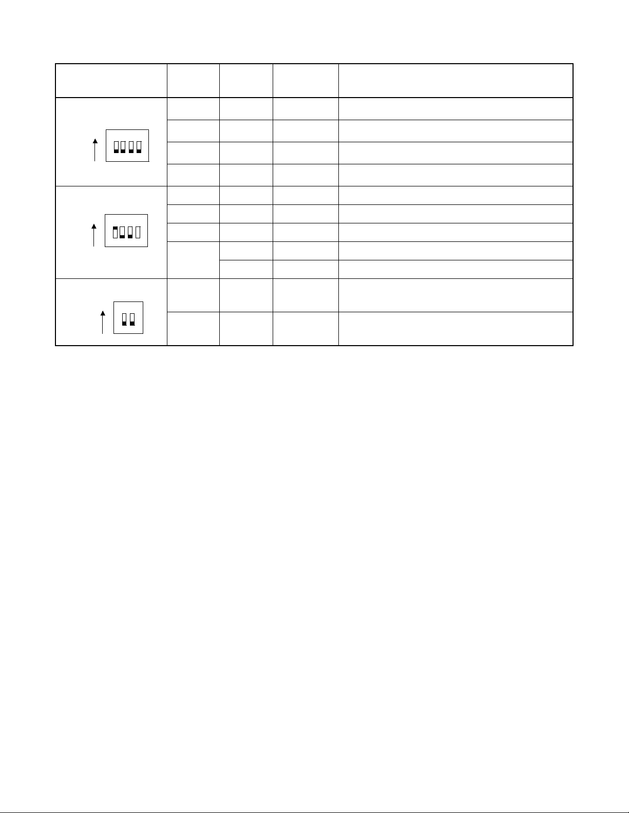
PA-AL16 (ALMC)
SWITCH NAME
SW4
ON
1234
SWITCH
NO.
SETTING
1OFF ×
2OFF ×
3OFF ×
4OFF ×
STANDARD
SETTING
Alarm Bus Fixed
Alarm Bus Fixed
Alarm Bus Fixed
Alarm Bus Fixed
SW5 1 ON × Fixed
ON
1234
2OFF × Fixed
3OFF × Fixed
ON For ACDP Dual System Config uration
4
OFF For ACDP Single System Configuration
SW6
ON
1OFF ×
12
2OFF ×
Alarm Bus Fixed
Alarm Bus Fixed
MEANING
CHAPTER 4 NDA-24282
Page 62
Revision 1.0
Page 82

SWIT CH SETT ING SHEET
PA-AL16 (ALMC)
MODULE SLOT NO.
SWITCH
NAME
SWITCH SHAPE REMARKS
APM 20 MB UP: Circuit card make busy
ON
DOWN:Circuit card make idle
EMASUP
ON
CPUSEL Middle = ACDP Dual System
ON
Down = ACDP Single System
MG (SW3) 0 = Single CPU Systems
0
9
9 = Multi CPU Systems
SW0
ON
1234
SW1 2 and 4 ON (Fixed)
ON
1234
SW2
ON
12
SW4 Alarm Bus
ON
1234
SW5 4 ON = Dual ACDP
ON
1234
4 OFF = Single ACDP
SW6 Alarm Bus
ON
12
NDA-24282 CHAPTER 4
Page 63
Revision 1.0
Page 83

PH-PC21 (APINT)
PH-PC21 (APINT)
1. Function
This circuit card is an inter-processor interface card and is used only for the Module Type ACD.
The card prov id es FIFO for mutual I/O bus connections for processor communication between the system
CPU and the ACDP.
TSW, INT
8-bit I/O Bus
GATE
32-bit MEM Bus
CPU
ECPY
MEM
Extended 8-bit I/O Bus
GATE
CPU
MEM
Position within the syste m
APINT APINT
8-bit I/O Bus
ACD Module
2. Mounting Location/Condition
The mounting location of this circuit card and the condition related to mounting are shown below.
Mounting Module LPRJ-A
00 01 02 03 04
PH-PC27
PH-PC27
PH-PC27
CPRAC-0 CPRAC-1
Note
Note:
This circuit card is mounted in any one of Slot No. 00~02.
CHAPTER 4 NDA-24282
Page 64
Revision 1.0
Page 84

3. Face Layout of Lamps, Switches, and Connectors
The face layout of lamps, switches, and connectors of this circuit card is shown below.
PH-PC21 (APINT)
CLKALM
OPE/MB
MB
AP1
AP0
SW01
4. Lamp Indications
The contents of lamp indications of this circuit card are shown in the table below.
LAMP NAME COLOR STATE
Green Remains lit while this circuit card is operating.
OPE/MB
Red Lights while this circuit card is in make-busy state.
CLKALM Red Lights when a failure has occurred to clocks for I/O bus synchronization.
5. Switch Settings
Standard settings of various switches on this circuit card are shown in the table below.
SWITCH
NAME
SWITCH NO. SETTING
STANDARD
SETTING
MEANING
MB
UP Circuit card make busy.
DOWN Circuit card make idle.
NDA-24282 CHAPTER 4
Page 65
Revision 1.0
Page 85

PH-PC21 (APINT)
SWITCH
NAME
SW0
SWITCH NO. SETTING
STANDARD
SETTING
ON
1
OFF
2ON× Fixed
ON
3
OFF
4OFF× Fixed
5OFF× Fixed
6ON
SW0-6 SW0-7 SW0-8 DEFINITION OF SOFTWARE TYPE
ON ON OFF
7OFF
OFF ON OFF
8ON
MEANING
When using this circuit card in the ACDP of
single-system configuration or when
connecting this circuit card to No. 0 system of
the ACDP of dual-system configuration.
When connecting this circuit card to No. 1
system of the ACDP of dual-system
configuration.
When the ACDP is provided by single-system
configuration.
When the ACDP is provided by dual-system
configuration.
To be used in ACD Module Type (SingleSystem Configuration)
To be used in ACD Module Type (DualSystem Configuration)
Others Not used
CHAPTER 4 NDA-24282
Page 66
Revision 1.0
Page 86

SWIT CH SETT ING SHEET
PH-PC21 (APINT)
MODULE SLOT NO.
LPRJ-A 00
01
02
SWITCH
NAME
SWITCH SHAPE REMARKS
MB UP: Circuit card make busy
ON
DOWN: Circuit card make idle
SW0
ON
1234567
8
NDA-24282 CHAPTER 4
Page 67
Revision 1.0
Page 87

PA-PC56-A (COPY)
PA-PC56-A (COPY)
1. Function
This circuit card provides the function to copy the contents of the RAM of both the standby (ST-Y) system
and the acti ve (ACT) syste m so that th e cont ents of the R AM of both syste m may be alw ays coinciding with
each other.
ALMC
IOC
RS-232C (Non-protocol)
APM
Position within the system
CPU CPU
(ACDP) (ACDP)
COPY COPY
CRAM CRAM
2. Mounting Location/Condition
The mounting locations of this circuit card and the conditions related to mounting are shown below.
Mounting Module APM
00 01 02 03 04 05 06 07 08 09 10 11 12 13 14 15 16 17 18 19 20 21 22 23
PA-PC56-A
PA-PC56-A
• This circuit card is not used when the ACDP is provided in a single-system configuration.
CHAPTER 4 NDA-24282
Page 68
Revision 1.0
For No.1 systemFor No.0 system
Page 88

3. Face Layout of Lamps, Switches, and Connectors
The face layout of lamps, switches, and connectors of this circuit card is shown below.
SW0
PA-PC56-A (COPY)
OPE
SREQ
MB
COPY
MBS1
4. Lamp Indications
The contents of lamp indications of this circuit card are shown in the table below.
LAMP NAME COLOR STATE
OPE Green Remains lit while this circuit card is operating in ACT state.
COPY Green Remains lit while this circuit card is operating in COPY mode.
MBS0
NDA-24282 CHAPTER 4
Page 69
Revision 1.0
Page 89

PA-PC56-A (COPY)
5. Switch Settings
Standard settings of various switches on this circuit card are shown in the table below.
SWITCH
NAME
MB
SREQ
SW0
SWITCH NO. SETTING
UP Circuit card make busy.
DOWN Circuit card make idle.
UP Separate mode request.
DOWN Separate mode request cancel (Copy mode).
ON
1
OFF
2OFF×
3OFF×
4OFF×
5ON×
6ON×
7ON×
8ON×
STANDARD
SETTING
MEANING
To be set in the case of System No. 0.
(To be mounted in Slot No. 08 of APMA.)
To be set in the case of System No. 1.
(To be mounted in Slot No. 17 of APMA.)
Fixed
CHAPTER 4 NDA-24282
Page 70
Revision 1.0
Page 90

SWITCH SETTING SHEET
PA-PC56-A (COPY)
MODULE SLOT NO.
APM-A\E 08
17
SWITCH
NAME
MB UP: Circuit card make busy
SREQ
SW0 1 ON = System No. 0
SWITCH SHAPE REMARKS
ON
12345678
ON
ON
DOWN:Circuit card make idle
1 OFF = System No. 1
NDA-24282 CHAPTER 4
Page 71
Revision 1.0
Page 91

PA-CP54 (CPU)
PA-CP54 (CPU)
1. Function
This circuit card is the CPU card (Central Processing Unit) which controls the ACD Module Type System.
Using the V6 0 microproces sor (32 bits), this CP U card provides programs and working memory. The card
is equipped with EPROM of 2MB and SRAM of maximum 384KB respectively.
CPU
I/O LOCAL BUS
APINT APINT
ALMC
IOC
RS-232C (Non-protocol)
ACD-MIS
ACD in IMX system (Module Type)
Position within the System
CPU CPU
(ACDP) (ACDP)
COPY COPY
CRAM CRAM
APM
2. Mounting Location/Condition
The mounting locations of this circuit card and the conditions related to mounting are shown below.
Mounti ng Modul e APM -A\E
00 01 02 03 04 05 06 07 08 09 10 11 12 13 14 15 16 17 18 19 20 21 22 23
PA-CP54
PA-CP54
CHAPTER 4 NDA-24282
Page 72
Revision 1.0
For No.1 systemFor No.0 system
Page 92

3. Face Layout of Lamp, Switches, and Connectors
The face layout of lamps, switches, and connectors of this circuit card is shown below.
PA-CP54 (CPU)
4. Lamp Indications
SW0
SW1
SW2
CPU OPE
MBR
CLKALM
COPALM
SW3
RESET
SW4
SENSE
The contents of lamp indications of this circuit card are shown in the table below.
LAMP NAME COLOR STATE
CPU OPE Green Remains lit while this circuit card is operating.
CLK ALM Red
Lights when a microprocessor operating clock failure has occurred in this circuit
card.
COP ALM Red Lights when a C-leve l infinite loop has occurred.
NDA-24282 CHAPTER 4
Page 73
Revision 1.0
Page 93

PA-CP54 (CPU)
5. Switch Settings
Standard settings of various switches on this circuit card are shown in the table below.
SWITCH
NAME
SWITCH NO. SETTING
STANDARD
SETTING
MEANING
UP Circuit card make busy.
MB
DOWN Circuit card make idle.
RESET PUSH Starting of reset of this circuit card.
0
1
For MMG (ICS), UMG (ICS), UMGx
(Normal Setting).
2
3
4
5
For IMG (IMX) (ICS), IMGx, IMGxh, IMGdxh
(Normal Setting).
6
7
8
When connecting the ACD System to
SENSE
9
MMG (ICS), UMG (ICS), UMGx; and when
the data memory of ACDP is to be cleared at
the time of AC DP initialization.
(CRAM Clear).
A
B
C
D
E
F
CHAPTER 4 NDA-24282
Page 74
Revision 1.0
When connecting the ACD System to
IMG (IMX) (ICS), IMGx, IMGxh, IMGdxh;
and when the data memory of ACDP is to be
cleared at the time of ACDP initialization.
(CRAM Clear).
Page 94

PA-CP54 (CPU)
SWITCH
NAME
SW0
SWITCH NO. SETTING
STANDARD
SETTING
ON × Memory Parity Alarm Inhibited.
1
OFF Memory Parity Alarm not inhibited.
ON External NMI input inhibited.
2
OFF × External NMI input not inhibited.
ON Memory Alarm NMI inhibited.
3
OFF × Memory Alarm NMI not inhibited.
ON COPALM inhibited.
4
OFF × COP ALM not inhibited.
5OFF× Fixed.
6OFF× Fixed.
ON
7
OFF
8OFF× Fixed.
MEANING
When ACDP is provided by dual-system configuration.
When ACDP is provi ded by single-system configuration.
SW1
ON
Sets Ready Alarm Dete ct Timing to l onger than
48 sec.
1
OFF ×
Sets Ready Alarm Dete ct Timing to l onger than
6 sec.
ON Sets the interval of C-Le v el int err upt to 4 m sec.
2
OFF ×
ON
Sets the interval of C-Level interrupt to 16
msec.
NMI input from an external memory system is
inhibited.
3
OFF ×
NMI input from an external memory system is
not inhibited.
4OFF× Fixed.
ON × Equipped with 1.5 MB CRAM area.
5
OFF Equipped with 3 MB CRAM area.
6ON× Fixed.
ON IMX Fixed.
7
OFF ICS Fixed.
ON × CRAM (PA-ME34) mounted.
8
OFF CRAM (PA-ME34) not mounted.
NDA-24282 CHAPTER 4
Page 75
Revision 1.0
Page 95

PA-CP54 (CPU)
SWITCH
NAME
SW2
SWITCH NO. SETTING
1
2
SW2-1 SW2-2 SETTING OF EPROM
ON ON When equipping 1M bit EPROM IC.
ON OFF When equipping 2M bit EPROM IC (standard).
OFF ON When equipping 4M bit EPROM IC.
OFF OFF Not used
ON × When equipping 1M bit SRAM IC.
3
OFF When equipping 256 K bit SRAM IC.
4
5
SW2-4 SW2-5 SETTING OF ROM AREAS
ON O N When providing 1MB of F00000H ~ FFFFFFH.
OFF O N
OFF OFF
ON ×
6
OFF
STANDARD
SETTING
When providing 2MB of F00000H ~ FFFFFFH and 00000H ~
0FFFFFH (standard setting).
When providing 4MB of F00000H ~ FFFFFFH and 00000H ~
2FFFFFH.
MEANING
When providing EE0000H ~ EFFFFFH and
E00000H ~ E3FFFFH as RAM areas.
When providing EE0000H ~ EFFFFFH as
RAM area.
SW3
ON ×
When equipping 256 kbit SRAM IC as parity
RAM.
7
OFF
When equi ppi n g 6 4 kbit SRAM IC as parity
RAM.
ON Test mode (Always mi s- h it stat e).
8
OFF × Normal operation mode.
1OFF× Fixed.
ON
When equi ppi n g 6 4 kbit SRAM IC as parity
RAM.
2
OFF ×
ON ×
3
When equipping 256 kbit SRAM IC as parity
RAM.
When equipping EPROM IC of either 1M bit
2M bit.
OFF When equipping EPROM IC of 4M bit.
ON ×
When equipping EPROM IC of either 1M bit
2M bit as parity ROM.
4
OFF
When equipping EPRO M IC of 4M bit as parity ROM.
CHAPTER 4 NDA-24282
Page 76
Revision 1.0
Page 96

PA-CP54 (CPU)
SWITCH
NAME
SW4
SWITCH NO. SETTING
STANDARD
SETTING
1OFF× Fixed
2OFF× Fixed
3ON× Fixed
4OFF× Fixed
5ON× Fixed
6OFF× Fixed
7OFF× Fixed
8OFF× Fixed
MEANING
NDA-24282 CHAPTER 4
Page 77
Revision 1.0
Page 97

PA-CP54 (CPU)
SWITCH SETTING SHEET
MODULE SLOT NO. SWITCH NAME SWITCH SHAPE REMARKS
APM 09
16
MBR UP : Circuit card make busy.
ON
DOWN:Circuit card make idle.
RESET
SENSE
SW0 7 ON = Dual ACDP
SW1 7 ON = IMX Systems
ON
12345678
ON
12345678
7 OFF = Single ACDP
8 ON = PA-ME34 Mounted
8 OFF = PA-ME34 Not Mounted
SW2 Standard
ON
12345678
SW3 Standard
SW4 Fixed
ON
ON
12345678
1234
CHAPTER 4 NDA-24282
Page 78
Revision 1.0
Page 98

PA-ME34 (CRAM)
1. Function
This circuit card is a RAM card for the ACD System and has memory capacity of 1.5 Mbytes.
PA-ME34 (CRAM)
ALMC
IOC
RS-232C (Non-protocol)
APM-A\E
Position within the system
CPU CPU
(ACDP) (ACDP)
COPY COPY
CRAM CRAM
2. Mounting Location/Condition
The mounting locations of this circuit card and the conditions related to mounting are shown below.
Mounting Module APM-A\E
00 01 02 03 04 05 06 07 08 09 10 11 12 13 14 15 16 17 18 19 20 21 22 23
PA-ME34
PA-ME34
PA-ME34
Note:
Note
For No. 1 sy s temFor No. 0 system
When ACDP is s ingle system configuration, this circuit card is mounted in Slot No. 08.
NDA-24282 CHAPTER 4
Page 79
Revision 1.0
Page 99

PA-ME34 (CRAM)
3. Face Layout of Lamps, Switches, and Connectors
The face layout of lamps, switches, and connectors of this circuit card is shown below.
SW0
OPE
DMWE
DMWD
DMWDK
PZ-ME17
SW1
4. Lamp Indications
The contents of lamp indications of this circuit card are shown in the table below.
LAMP NAME COLOR STATE
OPE Green Lights when the CP U h as accessed to t h e RAM in this card .
DMWE R ed Li g h t s wh en the dat a me mo ry area of this card is in wri te ena b le st at e.
DMWD R ed
Lights when the data memory area of this c ard is in writ e inhibite d state as set by the
DMWDK switch.
CHAPTER 4 NDA-24282
Page 80
Revision 1.0
Page 100

5. Switch Settings
Standard settings of various switches on this circuit card are shown in the table below.
PA-ME34 (CRAM)
SWITCH
NAME
DMWDK
SW0
SW1
SWITCH NO. SETTING
STANDARD
SETTING
UP Data memory area write inhibited
DOWN Data memory area write enable
1OFF×
2OFF×
3ON×
4ON×
5OFF×
6ON×
7OFF× Fixed
8OFF× Fixed
1
SW1-1 SW1-2
ON ON Write P ro tect is prov id ed.
OFF OFF Write Protect is not provided (Fixed).
2
Fixed
MEANING
Sets the RAM area to
$800000 ~ 8FFFFFH,
$C00000 ~ C7FFFFH
NDA-24282 CHAPTER 4
Page 81
Revision 1.0
 Loading...