

Page 1

Note
z Read thoroughly this manual before using the product.
z Keep this document along with the product in a safe place.
Built-in DAT
User’s Guide
Safety Precautions
This operation manual uses the symbols shown below to enable you to use the product safely
and correctly and to prevent injury and property damage.
WARNING
CAUTION
The following symbols are used to indicate danger or caution in handling the product.
This symbol indicates that using the product improperly in defiance of
this symbol may result in death or serious injury.
This symbol indicates that using the product improperly in defiance of
this symbol may result in injury or only damage to property.
Indicates that carelessness may invite danger.
Indicates a certain action is prohibited.
Indicates an action that the user must execute.
Indicates that you should not disassemble the unit.
Indicates that you should unplug the power code for safety.
– 1 –
Page 2
WARNI NG
" Never attempt to disassemble the unit such as opening the unit
cover.
Doing so may cause an electric shock or fire.
" Do not pour water or put anything into the unit.
If anything gets into the unit, turn the power off immediately and
disconnect the power plug from the outlet to avoid a short-circuit or
an electric shock.
" If the unit is damaged, or smoke, odor, or abnormal sound is
emitted, immediately turn off the POWER switch and disconnect the
power plug from the outlet to avoid a short-circuit or an electric
shock.
" Disconnect the power plug from the outlet when a thunderstorm is
likely to avoid an electric shock.
CAUTION
" Do not install the unit in a place where it is exposed to direct
sunlight or the temperature rises abnormally.
" Do not block the ventilation hole.
" Do not install the unit in a dusty or humid place.
" To avoid an electric shock, do not disconnect/connect the plug
while your hands are wet.
" Insert the power plug into the outlet as far as it will go to avoid an
electric shock or a fire.
" When connecting cables or wiring, observe the instruction in this
manual.
" Before connecting/disconnecting of the host computer or peripheral
devices, turn off the power and disconnect the power plug from the
outlet.
If the power plug is kept connected, you may get an electrical
shock.
" Do not install the unit in an unstable place.
It may cause the unit to fall down leading a human injury.
" Confirm that the connector is not damaged, the connector pin is not
bent or stained before connecting the cable. The damaged
connector, or stained or bent connector pin may cause a shortcircuit resulting in a fire.
" Use only the specified cable for connecting with the processing unit,
and confirm the destination connector. Using any other cables
than specified or connecting to incorrect connector may cause a
short-circuit resulting in a fire.
– 2 –
Page 3

CAUTION
" Do not use a handy telephone or a communication device near the
unit.
Doing so may cause an unexpected operation of the unit.
" .When disconnecting the power plug, do not pull the cable.
– 3 –
Page 4

CONTENTS
Safety Precautions ........................................................................................................................................ 1
Getting Started ........................................................................................................................................................ 5
Contents of the Package .......................................................................................................................................... 6
Unpacking .............................................................................................................................................. 6
Built-In DAT Hardware........................................................................................................................................... 7
Names and Functions of Built-In DAT and Setup Procedures (SCSI ID etc.).......................................... 7
Installing to the Basic Processing Unit.................................................................................................. 12
Using Built-In DAT.............................................................................................................................. 13
Cleaning ............................................................................................................................................... 14
Precautions........................................................................................................................................... 15
4mm Data Cartridge...................................................................................................................................... 16
Structure of the 4mm Data Cartridge..................................................................................................... 16
Specifications and Requirements for Storage and Shipment .................................................................. 16
Labeling ............................................................................................................................................... 17
Write-protection ................................................................................................................................... 17
Precautions on Handling ....................................................................................................................... 18
Standards for Prohibited Use................................................................................................................ 19
Cartridge Life....................................................................................................................................... 20
Preserving Critical Data........................................................................................................................ 20
Three-Generation Data Management .................................................................................................... 20
Appendix............................................................................................................................................................... 21
Major Specifications............................................................................................................................. 21
List of LED Indications......................................................................................................................... 22
Addendum............................................................................................................................................................. 24
For WindowsNT
TM
3.5/3.51 Users ....................................................................................................... 24
TRADEMARKS
WindowsNT™ is a registered trademark of Microsoft Corporation of the U.S. in the
U.S.A. and other countries.
– 4 –
Page 5

GETTING STARTED
This document is the user’s guide for Built-In DAT.
For operations of the basic processing unit, please refer to its attached manual.
– 5 –
Page 6
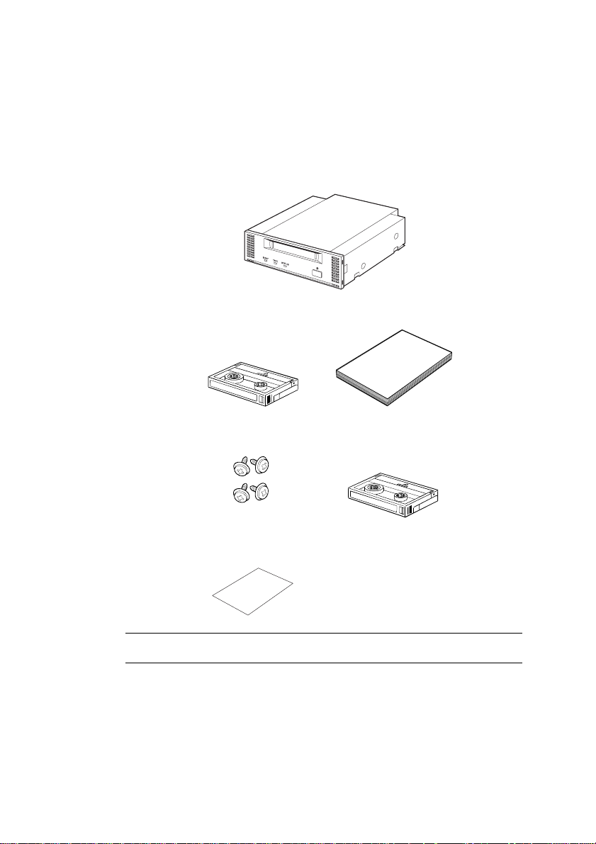
CONTENTS OF THE PACKAGE
Unpacking
Open the package and make sure everything including accessories is in it.
Built-In DAT
User’s GuideCleaning Cartridge
4 M3 Mounting Screws
DAT Handling Information
Data Cartridge
Make sure to attach this manual to the Built-in DAT when you transfer it to
someone else.
– 6 –
Page 7
BUILT-IN DAT HARDWARE
Names and Functions of Built-In DAT and Setup Procedures (SCSI ID etc.)
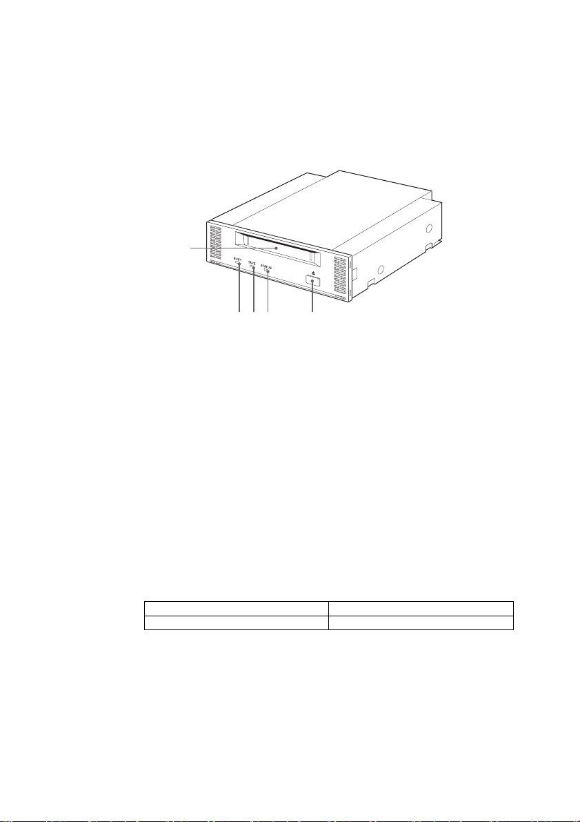
■Front Side
1
2 3 4 5
1 4mm Data Cartridge Slot
Insert the 4mm data cartridge into the slot. For procedures for inserting and ejecting
the cartridge, see the sections, “Inserting 4mm Data Cartridge” and “Ejecting 4mm
Data Cartridge”, respectively.
2 BUSY Indicator
Lights up when the data is being transmitted through the SCSI interface.
It blinks when read or write of the data in the inserted 4mm data cartridge is
successfully in progress.
Make sure not to power on/off the device while this lamp is lit. It may cause a read
error or critical damage to the 4mm data cartridge; or cause to write inappropriate
data.
3 TAPE Indicator
Lights up while the 4mm data cartridge is seated in the slot. It blinks under the
following conditions.
When inserting or ejecting the cartridge. Blinks at the same intervals.
When the cartridge is worn off. Repeats long turning-on and short turning-off.
– 7 –
Page 8
4 STATUS Indicator
5 EJECT Button
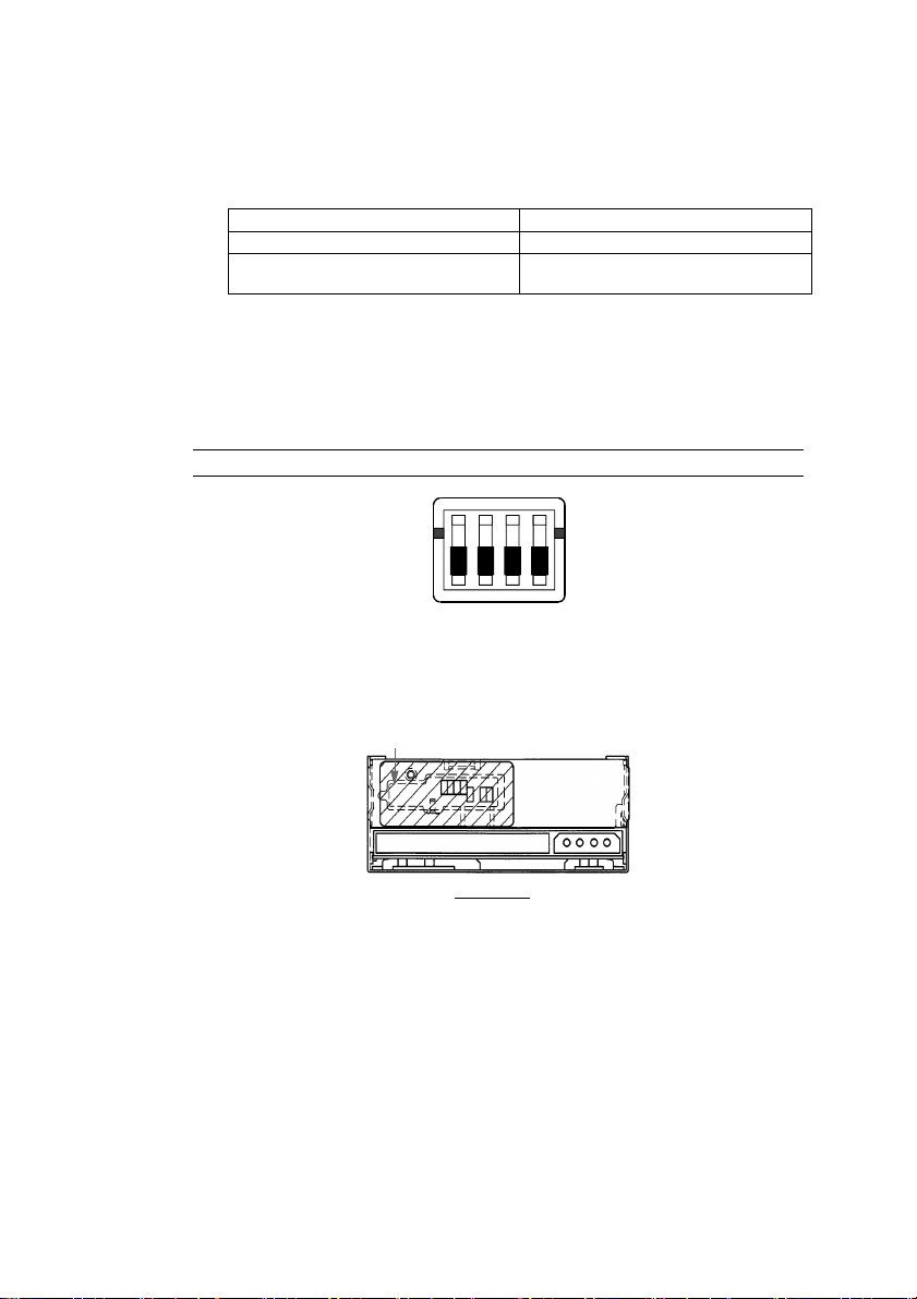
■Bottom Side
Do not change the initial setup of the dip switches as illustrated below.
■Rear Side
An anti-dust seal is applied to the back side of built-in DAT. Remove this seal when you
need to change the jumper settings, then replace it after the jumper settings have been
changed.
Lights up when the 4mm data cartridge inserted is write-protected. It blinks under
the following conditions.
When cleaning is required. Repeats long turning-on and short turning-off.
When tape cleaning completes. Blinks at the same intervals.
When the drive is out of order. Repeats short turning-on twice and long
turning-off.
Press this button to eject the cartridge out of the device.
N
O
1
2
3
4
Anti-dust seal
Built-In DAT
– 8 –
Page 9
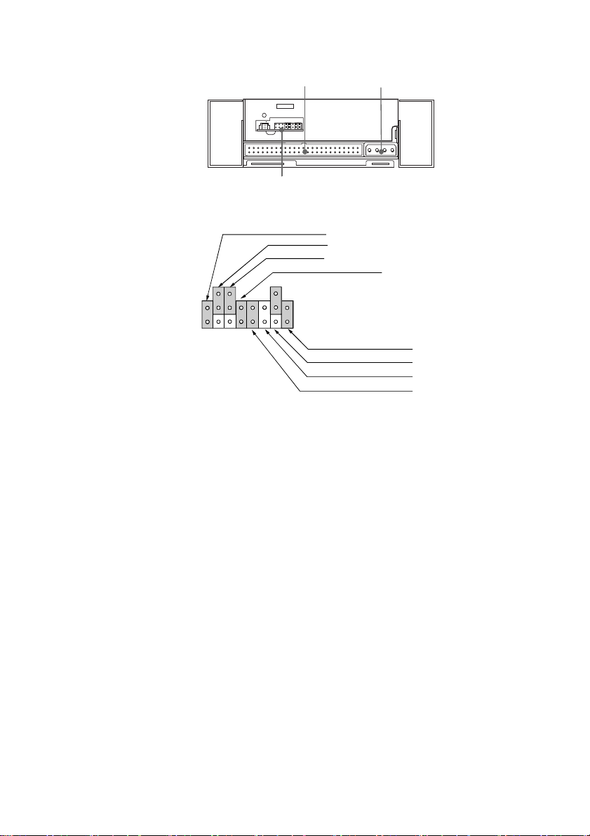
12
3
Jumper Positions upon Shipment
SCSI ID 2
SCSI ID 1
SCSI ID 0
No Data Compression (DC)
Terminator Power Supply (TMP)
Terminator (TMON)
RSV
SCSI Parity (PAR)
1 Signal Connector
SCSI signal connector for control over Built-In DAT.
2 DC Connector (+5V/+12V)
Connector for power supply to Built-In DAT. Plug in the power cable located in the
basic processing unit.
3 Optional Jumper Switch
Optional jumper switch for setting up the SCSI ID number, data compression, SCSI
parity, terminator, and terminator power supply. The jumper positions of the
switches are illustrated above.
– 9 –
Page 10

SCSI ID Number Jumper
The SCSI ID number jumper sets the SCSI ID number. The following table lists available
SCSI ID numbers and their settings.
SCSI ID 2 1 0 DC PAR
0
1
2
3
4*
5
6
7**
× × × - - - - -
× × ○ - - - - -
× ○ × - - - - -
× ○ ○ - - - - -
○ × × - - - - -
○ × ○ - - - - -
○ ○ × - - - - -
○ ○ ○ - - - - -
----
TMON TMP
○: Wired with the jumper.
×: Not wired with the jumper.
* The SCSI ID number is set to 4 upon shipment.
** Do not set the SCSI ID number to 7.
Terminator Power Supply Jumper (TMP)
This jumper sets whether to supply the terminator power onto the SCSI Bus.
Term Power 2 1 0 DC PAR
Supplied
Not supplied
- - - - - - - ○
- - - - - - - ×
----
TMON TMP
○: Wired with the jumper.
×: Not wired with the jumper.
The terminator power is set to be supplied from the drive upon shipment. Leave
this setting as it is at shipment.
– 10 –
Page 11

Terminator Setup (TMON)
To connect this device to the end of the SCSI BUS, make sure the BUS is terminated.
Otherwise, the SCSI BUS should not be terminated.
Terminator 2 1 0 DC PAR
Terminated
Not terminated
○: Wired with the jumper.
×: Not wired with the jumper.
- - - - - - ○ -
- - - - - - × -
----
TMON TMP
The terminator is disabled upon shipment.
Parity Jumper (PAR)
The parity jumper sets the parity function.
SCSI Parity 2 1 0 DC PAR
Parity enabled
Parity disabled
○: Wired with the jumper.
×: Not wired with the jumper.
- - - - ○ - - -
- - - - × - - -
----
TMON TMP
The parity function is set enabled upon shipment.
Leave this setting as it is at shipment.
Data Compression (DC)
This jumper sets whether data compression is enabled or disabled. To disable the data
compression function, set the function disabled with this jumper and reset the device by
powering off and on.
Data Compression 2 1 0 DC PAR
Data compression disabled
Data compression enabled
○: Wired with the jumper.
×: Not wired with the jumper.
- - - ○ - - - -
- - - × - - - -
----
TMON TMP
The data compression is set enabled upon shipment.
Leave this setting as it is at shipment.
– 11 –
Page 12

Installing to the Basic Processing Unit
The following describes an installation example to the basic processing unit.
Before installing this unit, make sure you unplug the power plug for the
basic processing unit you are using (such as a server or workstation
basic processing unit). Leaving the power cord plugged in presents an
electrical shock hazard.
1 Mount Built-In DAT to the following position illustrated in the figure below.
2 Connect the interface cable as illustrated in the following figure.
CAUTION
Place it in either location.
DC Power Cable
(Spare connector in the
system)
SCSI Interface Cable
(Spare connector in the
system)
! Confirm that the SCSI ID, terminator, and others are appropriately set before
installation.
! The SCSI ID of this device is set to 4 upon shipment. Make sure to set its
SCSI ID not to conflict with another device.
– 12 –
Page 13

Using Built-In DAT
■Inserting 4mm Data Cartridge
1 Insert the 4mm data cartridge to the direction indicated by the arrow illustrated in the
following figure. When the 4mm data cartridge is inserted to certain extent, it is
automatically drawn into the slot.
■Ejecting 4mm Data Cartridge
1 Press the EJECT button.
The 4mm data cartridge is drawn out.
The cartridge is drawn out upon completion of rewinding the tape. It takes 2
minutes at longest before the 4mm data cartridge is drawn out.
2 Pull out the 4mm data cartridge.
– 13 –
Page 14

Cleaning
■Cleaning the Head
1 Insert the attached cleaning cartridge into Built-In DAT.
Cleaning starts automatically and the cleaning cartridge will be drawn out
approximately 30 seconds later.
2 Take out the cleaning cartridge.
This completes cleaning. Use the device as usual.
! The attached cleaning cartridge is durable for 30 times of cleaning. Blinking of
the STATUS LED upon completion of cleaning indicates that the cleaning
cartridge is worn out. (See the section “STATUS Indicator” on page 4 for LED
indications.)
! Do not touch the tape surface of the cleaning cartridge nor rewind the tape for
re-use.
■Head Cleaning Period
Cleaning Tape Surface
Clean the head with the cleaning cartridge once a week before using the device. (The
cleaning period varies according to the environment where the device is used, i.e. amount of
dust, and frequency of use. To use the device everyday in the ordinary office, clean the
head once a week.)
– 14 –
Page 15

Precautions
■Precautions on the Storage and Operation Environment
! This device has a ventilation opening on its chassis to prevent the inside temperature
from rising. Do not cover the ventilation opening nor use the device in the place with
bad air flow. Also, do not store or operate this device in the place with extremely high
temperatures or sudden changes in temperature.
! Do not store or operate this device in the place exposed to the direct sunlight or the
place close to heat-generating equipment.
! Do not store or operate this device in the humid or dusty place.
! This device is composed of precision electronic parts. Do not apply any shock to the
device. Also do not store or operate this device in the place with vibration.
! It is dangerous to operate this device with water, liquid, or metal objects inside it.
Make sure no foreign material enter the device.
! Do not store or operate this device in the place filled with vaporized chemicals or the
place where it may come into contact with chemicals.
! Do not store or operate this device while it’s disassembled. It may cause an error or
electric shock.
! Do not store or operate this device with a heavy object on top of it.
■Other Precautions
When the outside of this device becomes dirty, gently wipe it with a soft cloth moistened
with water or a cleaning detergent. Use of volatile chemicals, such as thinner and
benzene, may cause deformation or discoloration. Applying insecticide may also cause
deformation or discoloration.
■Abnormality and Error
■Disposal
When you find any error or abnormality, such as smells and heat, plug out the power cable
and contact the authorized maintenance personnel or dealer.
When you dispose the unit, follow the rules and regulations in your country. Ask your
local government for details.
– 15 –
Page 16

4mm DATA CARTRIDGE
Structure of the 4mm Data Cartridge
Specifications and Requirements for Storage and Shipment
■Operation Requirements
Temperature
Humidity 20 to 80%
Holding Period If the 4mm data cartridge has been exposed to the environment that does not
■Storage Requirements
Temperature
Humidity 20 to 80%
Storage Place the 4mm data cartridge into the protection case and close the cover
■Shipment Requirements
Temperature
Humidity 20 to 80%
Temperature Gradient
Shipment Place the 4mm data cartridge into the protection case, then put the case into
10 to 35℃
The highest wet bulb temperature must be 26℃.
satisfy the operation and storage requirements, leave it in the operation
environment longer (max. 8 hours) than it has been in the above
environment before use. The temperature gradient must be 10℃/hour.
5 to 35℃
The highest wet bulb temperature must be 26℃.
for storage.
The case may be placed horizontally or vertically.
-30 to 35℃
The highest wet bulb temperature must be 26℃.
10℃/hour
a plastic bag and close the bag.
For shipment, pack the plastic bag containing the 4mm data cartridge in a
cardboard box to protect the cartridge against any force.
– 16 –
Page 17

Labeling
■Label Position
■Precautions on Labeling
! Use a label that is easy to remove and leaves no adhesive when removed to indicate
contents of the 4mm data cartridge.
! Do not use an eraser to erase indication of the contents for update. Replace the label
with a new one. (The INDEX labels come with the 4mm data cartridge.)
! Attach a label to the exact position illustrated in the previous section. Remove the old
label before replacing it with a new one.
! Use a label with the same size as the specified INDEX label when it is necessary to use
a non-specified one.
! On the attached INDEX label, there is a field to fill in the date of first use. Make sure
to fill it in. It will help determining the life of the 4mm data cartridge.
Write-protection
Placing the write-protection plug as illustrated in the right figure below protects contents of
the tape.
To prevent the written data from erasing, place the write-protection plug as illustrated in the
right figure below. Placing the write-protection plug as illustrated in the left figure below
allows the data to be written on the tape.
Label
Not write-protected Write-protected
– 17 –
Page 18

Precautions on Handling
■Precautions on Use
Before Use
! Do not use a 4mm data cartridge on which external damage, deformation, or bending is
found.
! To use the 4mm data cartridge stored in the environment that does not satisfy the
required temperature and humidity requirements, leave it in the operation environment
longer (max. 8 hours) than it has been in the above environment before use. If there is
an extreme difference in temperature between the storage and operation sites, do not
move the cartridge directly from the storage site to the operation site. Leave it in the
place with the temperature gradient of 10℃/hour and allow the 4mm data cartridge to
be accustomed gradually to the operation site.
In-device Period
Set the 4mm data cartridge as described in the section, “Inserting 4mm Data Cartridge”.
Tightly close the protection case after removing the 4mm data cartridge out of it, and store
it in the place with few dust.
After Use
Store the used 4mm data cartridge in the protection case and store it in the place with few
dust. It may be placed horizontally or vertically.
– 18 –
Page 19

■General Precautions
! Do not touch the tape. Also, do not open and close the tape cover.
! Do not place any magnetic objects close to the cartridge.
! Do not apply the direct sunlight to the cartridge or place it close to the heater.
! Do not apply any strong shock.
! Do not handle the cartridge while eating or smoking. Also keep it free from thinner or
alcohol.
! Keep the cartridge in the case for storage after use.
! Insert the cartridge gently into the equipment.
! Keep the 4mm data cartridge magnetic tape free from dust.
Standards for Prohibited Use
Replace the 4mm data cartridge with a new one if the following conditions fit.
! When the 4mm data cartridge receives any damage by applying strong shock such as
dropping it
! When the recording surface is exposed to any liquid (soft drinks, coffee, or tea), solvent,
metal powder, or cigarette ash
Remarks
Inserting the 4mm data cartridge in the above conditions into the equipment may place
damage or dirt to the head or equipment, causing an error of the equipment. Also inserting
the 4mm data cartridge into the equipment with the dirty or damaged head may place dirt or
damage to the cartridge, making the whole situation disastrous.
– 19 –
Page 20

Cartridge Life
Data cartridges are subject to wear during every read and write operation. Continuing to use
a cartridge eventually leads to errors, and further use could result in loss of stored data.
Cartridges should therefore be replaced periodically.
The useful life of a cartridge depends on the operating environment, but the following table
serves as an approximate guideline to cartridge life.
Usage Frequency Estimated Useful Life
Once per week One year
Two to three times per week Six months
Daily Three months
! The above estimates may be shortened by operating environment conditions
(temperature, humidity, dust, etc.)
To manage data cartridges for optimum useful life, we recommend the following steps:
! Assign control numbers to new data cartridges, and write the numbers on the labels.
! Maintain a tape control list, including the date of first use and the expected useful life of
each cartridge.
! Refer to the control list and tape labels to determine when cartridges are reaching the
end of their useful lives (or if read/write errors occur), and remove them from use.
The chemical compounds that compose the magnetic layer of the tape will deteriorate over
time. The rate of this deterioration is greatly influenced by the storage environment
(temperature and humidity), so even if never used, cartridges should be replaced about three
years after purchase.
Preserving Critical Data
To preserve critical data or programs, we recommend saving to two tapes: a main and a sub
copy.
Also, when writing the backup copies, we recommend confirming the copy by using the
verify function of the backup software. Please refer to the documentation for the backup
software regarding use of the verify function.
By taking these steps, even if read errors are encountered as a result of dirt or dust on the
tape, the other tape can be used for data recovery, preventing loss of critical data and
programs.
Three-Generation Data Management
We recommend using a three-generation data management system for backing up data
saved on disk.
This system uses three tapes (call them A, B and C), with the disk data saved in the order
A-B-C as follows: disk data is saved to tape A on the first day, tape B on the second day,
and tape C on the third day.
With this system, if, for example, a read error was found on tape C, most data could still be
restored from tape B, and even if a read error was found on tape B, important data could
still be restored from tape A.
– 20 –
Page 21

APPENDIX
Major Specifications
■Performance
Memory Capacity 12 G bytes (Compressed: 24 G bytes)
• The value for compressed use is estimated with double compressibility. The compressibility
varies according to the data pattern.
Bit Error Code 10
Data Transfer Speed (TAPE) 1,180K bytes / second (non-compressed)
Burst Data Transfer Speed (SCSI) 5M bytes / second (max., asynchronized)
Initializing Pe riod less than 3 seconds
Loading Period less than 24 seconds
Unloading Pe riod less than 20 seconds
Rewinding Pe riod less than 80 seconds (with the 125m tape in use)
■Environment Requirements
-15
or less
10M bytes / second (max., synchronized)
Operation
Shipment
Storage
■DC Power Specification
Voltage
Current (Typ.) 1.0A 0.21A
■Size and Weight
Ambie nt
Temperature
10 to 35℃
-30 to 40℃
-5 to 40℃
Relative
Humidity
20 to 80%
10 to 90%
10 to 90%
5V±5% 12V±10%
Width 149mm
Height 41.2mm
Depth 149.8mm
Weight 0.91kg or less
41.2mm
149mm 149.8mm
Maximum Wet Bulb
Temperature
26℃ with no condensation
26℃ with no condensation
26℃ with no condensation
– 21 –
Page 22

List of LED Indications
Tape
Condition
Normal Normal
Normal Normal
Normal Normal
Normal Normal
Normal Normal
Normal Normal
Normal Normal
Normal or
Abnormal
Device
Condition
Normal
BUSY Lit or unlit
TAPE Unlit
STATUS Unlit
BUSY Blinking at the
TAPE Lit
STATUS ***
BUSY Blinking at the
TAPE Blinking at the
STATUS ***
BUSY Lit, unlit, or
TAPE Lit
STATUS ***
BUSY ***
TAPE Lit
STATUS Lit
BUSY Unlit
TAPE Lit
STATUS Blinking at the
BUSY ***
TAPE ***
STATUS Repeats long
BUSY ***
TAPE Repeats long
STATUS ***
DAT Device
LED LED State Meaning
SCSI is a ctive while BUSY is
lit.
No data cartridge is inserted.
The data cartridge is under
same intervals
operation. Read/write or
write is in progres s.
The data cartridge is be ing
same intervals
inserted or ejected.
same intervals
The data cartridge is inserted. (Note)
blinks at the
same intervals.
The inserted data cartridge is
write-protected.
The cleaning cartridge is used
up.
same intervals
Cleaning the head is
requested.
turning-on and
short turningoff.
The data cartridge is inserted
and an error that exceeds the
turning-on and
short turningoff.
defined media warning
threshold occurs. “Warning
Only” (The data cartridge is
worn off. )
Measure
(Note)
Make sure not to power off in
these LED states.
(Note)
Make sure not to power off in
these LED states.
Make sure not to power off in
these LED states.
(Note)
Make sure not to power off in
these LED states.
• Replace the cleaning
cartridge with a new one.
Do not reuse the old
cleaning cartridge.
• Perform cleaning the
head.
• If the same error occurs
right after the cleaning,
use a new data cartridge.
• Clean the head with the
standard cleaning
cartridge. If the same
error occurs right after the
cleaning, use a new data
cartridge (or clean the
head again and use a new
data cartridge).
– 22 –
Page 23

Tape
Condition
Normal or
Abnormal
Device
Condition
Normal or
Abnormal
DAT Device
LED LED State Meaning
BUSY Repeats short
Reset awaiting state
turning-on and
long turningoff.
TAPE ***
STATUS ***
Measure
• Pressing the EJECT
button does not ejects the
data cartridge. There
may be a hardware error
in the DAT device.
• Restart the device by
powering off and on.
Persisting the same error
after the restart indicates a
hardware failure.
Replace the DAT device.
Normal or
Abnormal
Normal or
Abnormal
Abnormal Abnormal
BUSY ***
TAPE Repeats short
tuning-on and
long turningoff.
STATUS ***
BUSY ***
TAPE ***
STATUS Repeats short
turning-on
twice and long
turning-off.
Ejection awaiting state
The device is faulty.
• Eject the data cartridge.
Use a new data cartridge.
Persisting this error after
replacement of the data
cartridge indicates a
hardware failure.
Replace the DAT device.
• The DAT device has a
hardware failure.
• Replacement of the DAT
device is required. The
data in the data cartridge
in use may destroyed due
to the hardware failure.
use another data cartridge.
Do not reuse the DAT
device and data cartridge
that had this error.
***indic ate s that the LED stat e va ries according to the state of the DAT device but does not affect the meaning or
measure.
– 23 –
Page 24

ADDENDUM
For WindowsNTTM 3.5/3.51 Users
Using this device with NTBACKUP of WindowsNTTM requires the tape device driver
“4mm SONY Drive” to be installed.
Procedure for Adding the Tape Device Driver
Preparation
(1) Make the WindowsNTTM installation media (CD-ROM) ready to use.
Installation Procedure
(1) Select “ WindowsNTTM Setup ” in the WindowsNTTM main group.
(2) Select “ Add/Remove Tape Device ” from the “ Options ” menu of “ WindowsNT
Setup ”.
(3) Select Add on the “ Tape Device Setup ” window.
(4) Select “ 4millimeter SONY drive ” for the device name on the “ Select Tape Device
Option ” window and select the “ Install ” button.
(5) The tape device driver is installed from the WindowsNTTM installation media (CD-
ROM).
Confirm that the CD-ROM drive name is correct.
* Set the WindowsNTTM installation media (CD-ROM) in the CD-ROM drive.
(6) Select the “ Continue ” button.
(7) Confirm that “ 4millimeter SONY drive ” is included in the list of installed tape
devices and select “ Close ”.
(8) Exit “ WindowsNTTM Setup ” and restart the system.
* The installed tape device is not effective before the system is restarted.
TM
– 24 –
Page 25

Page 26

Page 27

Page 28

The contents of this guide are subject to revision without prior notice.
Built-in DAT
First Edition, August 2000
Second Edition, March 2001
Third Edition, August 2002
User’s Guide
 Loading...