

Page 1

E
XPRESS
■■■■■■■
■■■■■■■
■■■■■■■
■■■■■■■
■■■■■■■
■■■■■■■
5800/System Rack
()
Service Guide
■■■■■■■
■■■■■■■
■■■■■■■
■■■■■■■
■■■■■■■
■■■■■■■
■■■■■■■
■■■■■■■
Page 2

xxx
Page 3

E
XPRESS
■■■■■■■
■■■■■■■
■■■■■■■
■■■■■■■
■■■■■■■
■■■■■■■
5800/System Rack
()
Service Guide
■■■■■■■
■■■■■■■
■■■■■■■
■■■■■■■
■■■■■■■
■■■■■■■
■■■■■■■
■■■■■■■
Page 4

Proprietary Notice and Liability Disclaimer
The information disclosed in this document, including all designs and related materials, is
the valuable property of NEC Computers Inc. and/or its licensors. NEC Computers Inc.
and/or its licensors, as appropriate, reserve all patent, copyright and other proprietary rights
to this document, including all design, manufacturing, reproduction, use, and sales rights
thereto, except to the extent said rights are expressly granted to others.
The NEC Computers Inc. product(s) discussed in this document are warranted in
accordance with the terms of the Warranty Statement accompanying each product.
However, actual performance of each such product is dependent upon factors such as
system configuration, customer data, and operator control. Since implementation by
customers of each product may vary, the suitability of specific product configurations and
applications must be determined by the customer and is not warranted by NEC Computers
Inc.
To allow for design and specification improvements, the information in this document is
subject to change at any time, without notice. Reproduction of this document or portions
thereof without prior written approval of NEC Computers Inc. is prohibited.
Trademarks
PowerChute is registered trademark of American Power Conversion Corporation.
SmartSlot is a trademark of American Power Conversion Corporation.
All other product, brand, or trade names used in this publication are the trademarks or registered
trademarks of their respective trademark owners.
PN: 456-01544-000
Copyright 2000
NEC Computers Inc.
15 Business Park Way
Sacramento, CA 95828
All Rights Reserved
Page 5

Contents
Contents
ContentsContents
Proprietary Notice
Using This Guide................................................................................................................... v
Text Conventions..................................................................................................................vi
Related Documents...............................................................................................................vi
Safety Notices......................................................................................................................vii
Safety Notices for Users Outside of the U.S.A. and Canada..........................................vii
Care and Handling..............................................................................................................viii
Planning Your Site ............................................................. 2-1
Equipment Location ...........................................................................................................2-2
Space Requirements ......................................................................................................2-2
Environmental Conditions.............................................................................................2-4
Floor Construction.........................................................................................................2-5
System Rack Placement......................................................................................................2-7
Air Conditioning.................................................................................................................2-9
Cooling Capacity........................................................................................................... 2-9
Electrical Facilities ...........................................................................................................2-10
Uninterruptible Power Source (UPS) ..........................................................................2-10
Power Distribution Unit (PDU)...................................................................................2-10
Grounding Requirements..................................................................................................2-11
Planning Your System Rack Configuration ..................... 3-1
Cabling Constraints ............................................................................................................3-2
Cable Summary ..................................................................................................................3-2
RAID Cable Restrictions...............................................................................................3-3
Concentrator Cable Lengths.......................................................................................... 3-3
Vertical Spacing .................................................................................................................3-3
Configuration Guidelines ...................................................................................................3-6
Calculating Load and Determining UPS On-Battery Run Time .......................................3-8
Installing the System Rack................................................ 4-1
Introduction ........................................................................................................................4-2
What You Need.............................................................................................................4-2
Unpacking the System Rack and Components...................................................................4-3
Opening Front and Rear Doors .....................................................................................4-5
Removing Rack Side Panels..........................................................................................4-6
Leveling the System Rack..................................................................................................4-7
Installing Rack Frame Link Kits ........................................................................................4-8
What You Need.............................................................................................................4-8
Attaching the Stabilizer to the System Rack ....................................................................4-10
Contents iii
Page 6

Installing Rack Components..............................................5-1
Tools Required................................................................................................................... 5-3
Installing Rack Components.............................................................................................. 5-3
Recommendations and Warnings....................................................................................... 5-4
Installing the UPS......................................................................................................... 5-4
Installing the Interface Expander Accessory ........................................................ 5-6
Installing the UPS ................................................................................................. 5-7
Connecting Your Master and Protected servers (BSUs)..................................... 5-10
Installing a Power Distribution Unit........................................................................... 5-12
Installing a Keyboard Tray......................................................................................... 5-13
Installing the Concentrator ......................................................................................... 5-14
Installing Blank Panels ............................................................................................... 5-17
Installing a Monitor Tray............................................................................................ 5-18
Connecting the Console Monitor................................................................................ 5-19
Connecting Servers (BSUs) to the Concentrator ........................................................ 5-19
Illustrated Parts Breakdown ..............................................6-1
Field Replaceable Units ..................................................................................................... 6-3
Options............................................................................................................................... 6-5
Index
iv Contents
Page 7

Using This Guide
This guide contains the information necessary to install the Express5800 System Rack.
This guide is written for knowledgeable users, trained customer engineers, service
center personnel, and dealers. Please read these installation procedures in their entirety
before starting.
This guide contains the following information:
Chapter 1, “Introduction” introduces you to the Express5800 System Rack models
!
and describes the major system components that may be installed within the rack
enclosure. See this chapter to familiarize yourself with your server rack.
Chapter 2, “Planning Your Site” provides information about your Express5800
!
System Rack that you and your facility planners must have to properly prepare the
site for rack installation.
Chapter 3, “Planning Your System Rack Configuration” provides information on
!
rack cabling, component space requirements, and component power consumption.
Chapter 4, “Installing the System Rack ” provides information on unpacking and
!
installing your system rack at your selected site.
Chapter 5, “Installing Rack Components” contains helpful information for
!
configuring and installing system components into the system rack.
Chapter 6, “Illustrated Parts Breakdown” contains the exploded view and parts lists
!
for the rack’s major assemblies. Part numbers are provided for optional hardware.
Using This Guide v
Page 8
Text Conventions
This guide uses the following text conventions.
Warnings, cautions, and notes have the following meanings:
Warnings alert you to situations that could result in serious personal injury or loss
of life.
Cautions indicate situations that can damage the system hardware or software.
:
Note
Names of keyboard keys are printed as they appear on the keyboard. For example,
!
Ctrl, Alt, or Enter.
Notes give important information about the material being described.
!
WARNING
!
CAUTION
Text or keystrokes that you enter appear as boldface type. For example, type abc123
!
and press ENTER.
File names are printed in uppercase letters. For example, AUTOEXEC.BAT.
!
Related Documents
In addition to this guide, the following system documentation is included with your
server either as electronic files on E
server.
Express5800 Server User’s Guide
!
Your Server User’s Guide provides you with the information on installing your
server into the system rack. Your server user’s guide is located on the
ExpressBuilder CDROM that came with your system.
XPRESSBUILDER
or as paper copy shipped with your
vi Using This Guide
Page 9

Safety Notices
Caution: To reduce the risk of electric shock which could cause personal injury,
!
follow all safety notices. The symbols shown are used in your documentation and on
your equipment to indicate safety hazards.
Warning: Detachable power supply cords are intended to serve as the disconnect
!
device.
Warning: This equipment has a 3-wire, grounded power cord. To prevent electrical
!
hazards, do not remove or defeat the ground prong on the power cord. Replace the
power cord if it gets damaged. Contact your dealer for an exact replacement.
Warning: The DC push-button on/off switch on the front panel of your server does
!
not turn off the system AC power. Also, +5vdc is present on the system board
whenever the AC power cord is connected between the system and an AC outlet.
Before doing the procedures in this manual, make sure that your system is powered
off and unplug the AC power cord from the back of the chassis. Failure to disconnect
power before opening your system can result in personal injury and equipment
damage.
!
All Servers and Peripherals installed inside a rack:
In the U.S.A. and Canada, the power cord must be a UL-listed detachable power cord
(in Canada, CSA-certified), type ST or SJT, 16 AWG, 3-conductor, provided with a
molded-on NEMA type 5-15 P plug cap at one end and a molded-on cord connector
body at the other end. The cord length must not exceed 6.56 feet (2.0 meters).
Outside the U.S.A. and Canada, the plug must be rated for 250 VAC, 10 amp minimum,
and must display an international agency approval marking. The cord must be suitable
for use in the end-user country. Consult your dealer or the local electrical authorities if
you are unsure of the type of power cord to use in your country. The voltage change
occurs via a switch in the power supply.
Warning: Under no circumstances should the user attempt to disassemble any
!
power supply. A power supply has no user-replaceable parts. Inside the power
supply are hazardous voltages that can cause serious personal injury. A defective
power supply must be returned to your dealer.
Safety Notices for Users Outside of the U.S.A. and Canada
PELV (Protected Extra-Low Voltage) Integrity: To ensure the extra-low voltage
!
integrity of the equipment, connect only equipment with mains-protected
electrically-compatible circuits to the external ports.
Using This Guide vii
Page 10
Remote Earths: To prevent electrical shock, connect all local (individual office)
!
computers and computer support equipment to the same electrical circuit of the
building wiring. If you are unsure, check the building wiring to avoid remote earth
conditions.
Earth Bonding: For safe operation, only connect the equipment to a building supply
!
that is in accordance with current wiring regulations in your country.
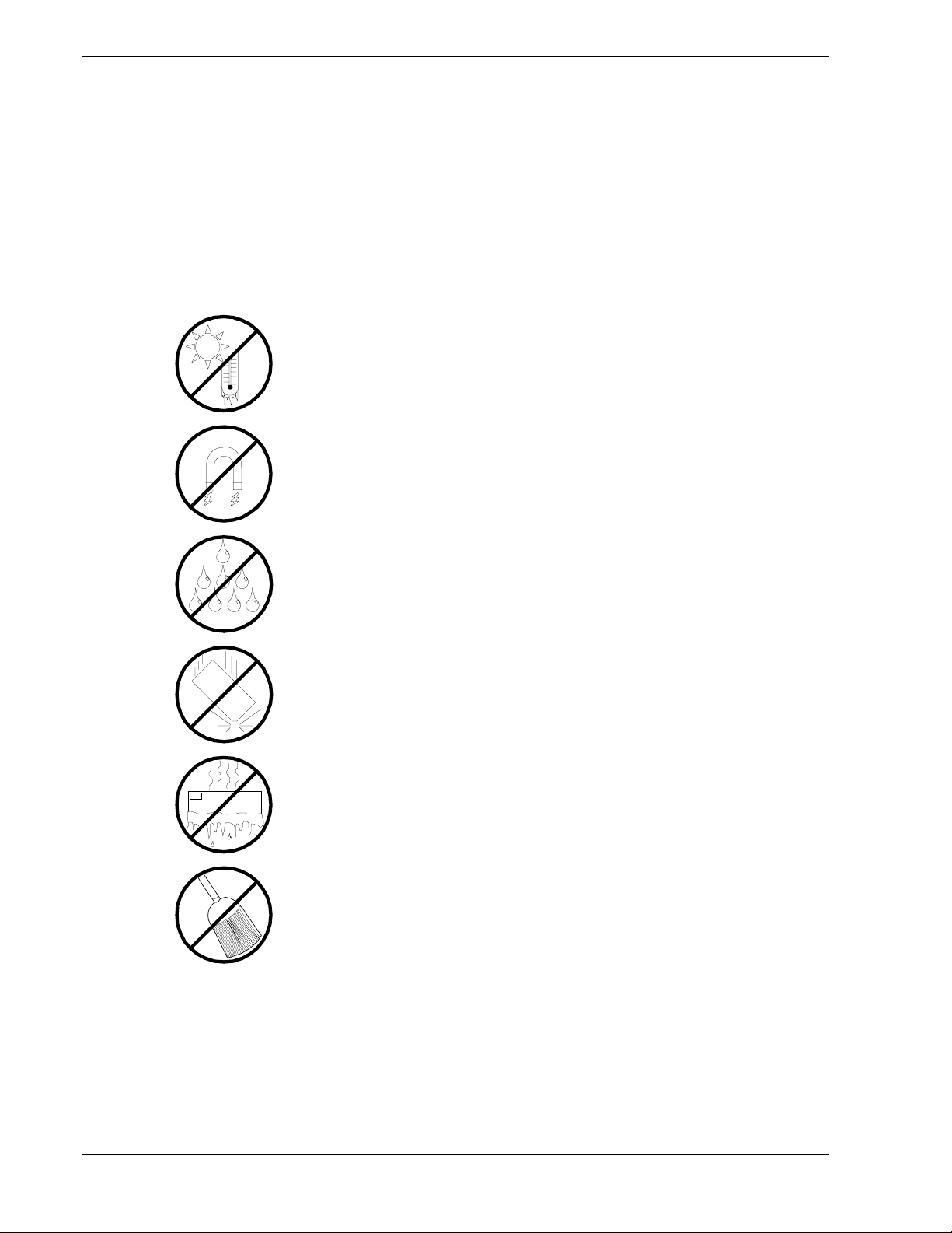
Care and Handling
Use the following guidelines to properly handle and care for your system.
Protect the system from extremely low or high temperatures. Let
the system warm (or cool) to room temperature before using it.
Keep the system away from magnetic forces.
Keep the system dry. Do not wash the system with a wet cloth or
pour fluid into it.
Protect the system from being bumped or dropped.
Check the system for condensation. If condensation exists, allow it
to evaporate before powering on the system.
Keep the system away from dust, sand, and dirt.
viii Using This Guide
Page 11

Introduction
Introduction
!
System Rack Models
!
Configurator Assistant
!
42U System Rack
!
Multi-Bay System Rack
!
1
Page 12

Introduction
The system rack is an attractive enclosure designed to store and protect your server
components. The system rack allows you to integrate your server, monitor, and other
components in one cabinet that may be installed in a limited amount of floor space in
just about any location. Removable side walls and front and rear doors ensure easy
access to all installed components, while a special locking system prevents
unauthorized access.
System Rack Models
The system rack is available in three models: 42U, 36U and 27U. The only difference in
the three models is the height of the rack. The size of each system rack is as follows:
Model 42U –
!
Model 36U – 18
!
Model 27U – 14
!
This guide contains the information necessary to install the 42U System Rack. The
installation process for the 36U and 27U is similar to the 42U model.
2000mm (78.7in) H x 600mm (23.6in) W x 1000m (39.4in) D.
00mm (70.9in) H x 600mm (23.6in) W x 1000m (39.4in) D.
00mm (55.1in) H x 600mm (23.6in) W x 1000m (39.4in) D.
Express5800 Configuration Assistant
The Express5800 Configurator Assistant is a software program that provides detailed
technical information on building server configurations. This program is especially
helpful when configuring systems that will be installed into a system rack. Contact your
sales representative for more information on the Express5800 Configuration Assistant.
1-2 Introduction
Page 13
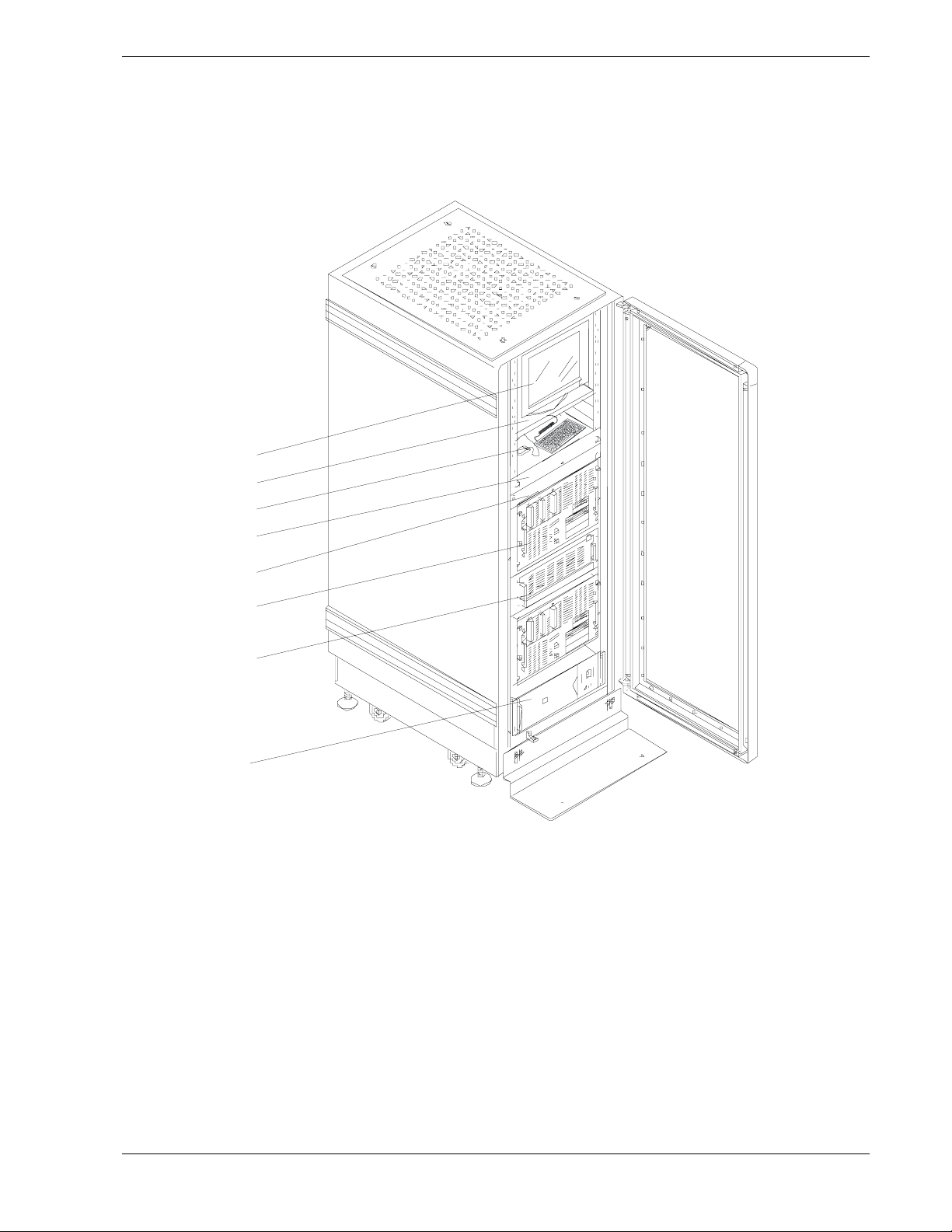
42U System Rack
Figure 1-1 illustrates a typical 42U system rack enclosure, including the components
that install into the rack. Table 1-1 lists and describes several system components
installed in the system rack.
A
B
C
D
E
G
H
F
Figure 1-1. Typical 42U System Rack Enclosure
Introduction 1-3
Page 14

Table 1-1 lists the typical system rack components shown in Figure 1-1.
Table 1-1. Typical System Rack Components
Item Component Description
A Monitor (LCD) A monitor that serves as your standard output device.
B Monitor Tray Supports your monitor when installed in the rack.
C Keyboard and Mouse Standard input devices.
D Keyboard and Mouse Tray Supports your keyboard and mouse when installed in the
rack.
E 8-Port Concentrator Allows you to connect a single keyboard, mouse, and
monitor to up to eight servers
F Express5800 Server Contains the Central Processing Unit (CPU), memory,
disks, and other support hardware.
G Disk Expansion Unit Supports RAID configuration as well as disk expansion.
H Power Distribution Unit (not
shown)
High-performance,
line-interactive, Uninterruptible
Power Source (UPS)
If you are not using an Uninterruptible Power Source
(UPS), AC power is distributed to system components
through a Power Distribution Unit (PDU).
Provides clean, reliable AC power to rack components to
protect them from power blackouts, brownouts, swells,
sags, surges, and interference
the UPS can be used together with APC™ PowerChute
software to automate power protection services to
plus
up to three Servers.
®
1-4 Introduction
Page 15
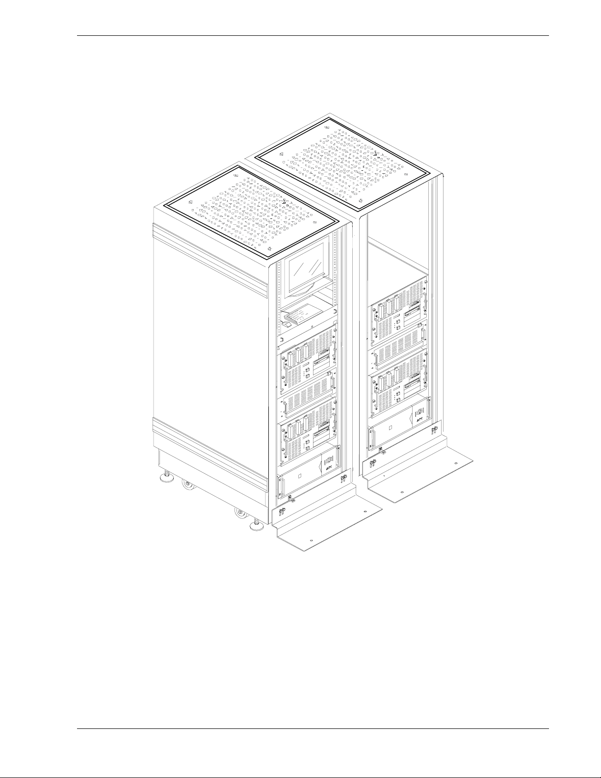
Multi-Bay System Rack
System racks can be quickly and easily joined together to accommodate large server
configurations as shown in Figure 1-2.
Figure 1-2. Multi-Bay System Rack
Introduction 1-5
Page 16

Page 17

Planning Your Site
Equipment Location
!
System Rack Placement
!
Air Conditioning
!
Electrical Facilities
!
Grounding Requirements
!
2
Page 18

Equipment Location
When planning your facilities, the following guidelines must be considered:
Does the allocated space allow for the proper installation of the
!
equipment and the performance of operation and maintenance activities?
Are the environmental conditions suitable for reliable operation?
!
Is the construction of the floor appropriate for the weight of the
!
equipment being installed?
Will the air conditioning maintain adequate temperature and humidity
!
conditions for the equipment being installed?
Are the proper electrical facilities available and adequate for the
!
equipment being installed?
Will future expansion be necessary or possible?
!
To plan your facilities, you must know your system configuration.
Space Requirements
The system rack requires an area that can:
Accommodate the height of the cabinet, which is 78.7 inches, (2 meters).
!
Provide a clearance above the rack of 16 inches (400 mm).
!
The space requirements of the area surrounding a single cabinet are given in
Figure 2-1. Note that the overall width should be increased by 23.4 inches for
each additional cabinet that is required by your system.
2-2 Planning Your Site
Page 19
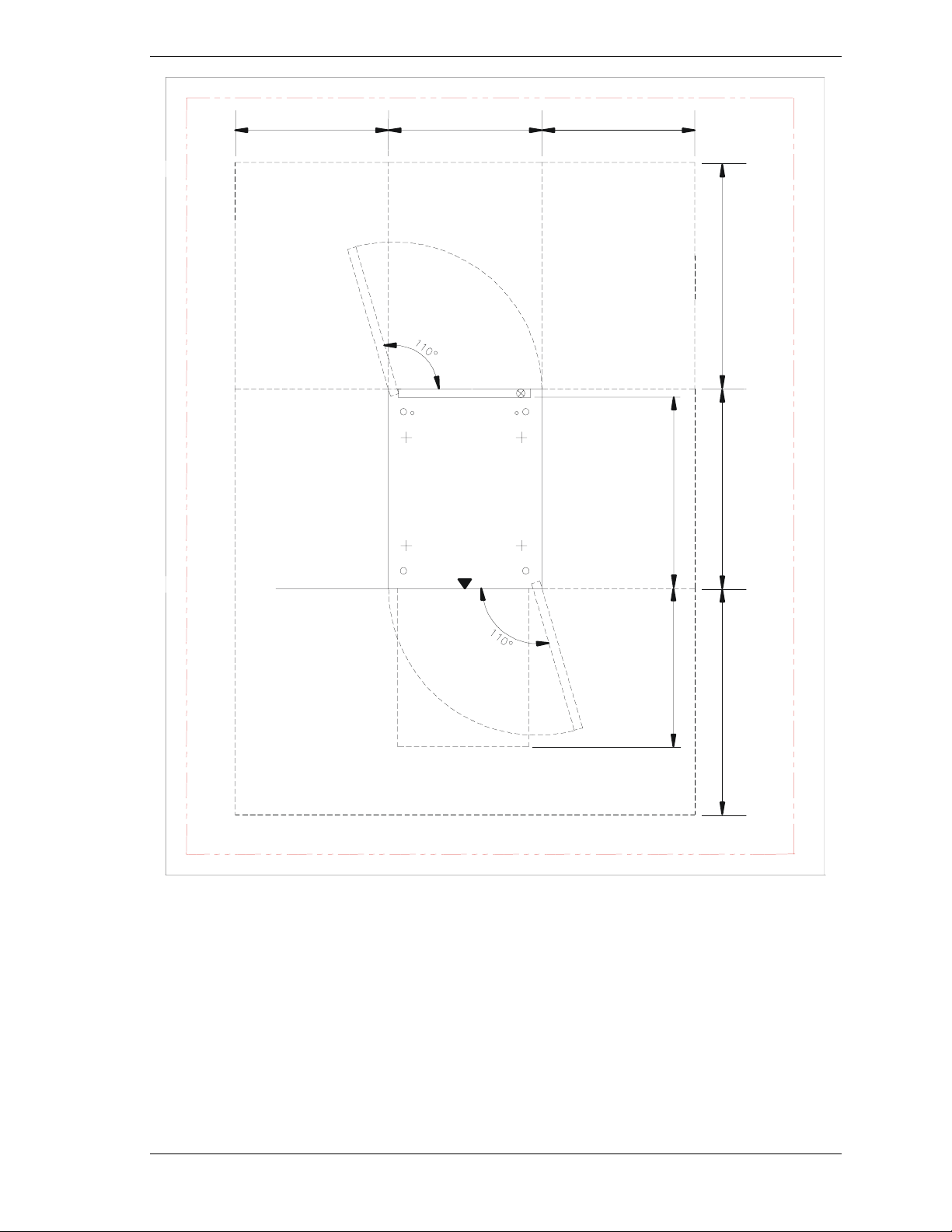
23.6" (600mm) 23.6" (600mm) 23.6" (600mm)
39.4"
(1000mm)
39.4"
(1000mm)
26.3"
(668mm)
Figure 2-1. System Rack Space Requirements
41.0"
(1041mm)
39.4"
(1000mm)
Planning Your Site 2-3
Page 20

Environmental Conditions
The location should be examined for the following environmental hazards:
Dust - floating dust must be kept to no more than 0.3 mg/m3. Dust should
!
be held to less than 0.15 mg/m
Radio Frequency (RF) - Normally, there is no need to worry about the
!
effect of radio frequency interference on computer operations. In areas
where strong waves are generated or where a high-frequency device is
installed on the same floor as the server, radio frequency can affect the
functionality of the system.
Magnetic Fields (MF) - Normally, there is no need to worry about the
!
effect of magnetic fields on computer operations. If the server is installed
near cables or transformers that permit the flow of high currents,
functionality can be affected.
3
.
2-4 Planning Your Site
Page 21

Floor Construction
(
)
Aspects of floor construction, such as load capacity and construction materials,
must be considered when installing one or more rack systems.
Note:
Use Table 2-1 to calculate the load that each rack of your system configuration
places on the floor.
The rack supports up to 551.2 lbs. (250 kg).
Table 2-1. Equipment Weight
Component Weight
(approx.)
System Rack (42u) 253 lbs.
114.8Kg.
Express5800/120Ld 66.1 lbs.
(30.0Kg.)
Express5800/120Mc2 66.1 lbs.
(30.0Kg.)
Express5800/120Mc3 66.1 lbs.
(30.0Kg.)
Express5800/180Ra-7 165 lbs.
(75.0Kg.)
Express5800 ES1400 38.0 lbs.
(17.2Kg.)
Express5800 HX4500 207 lbs.
(94.0Kg.)
Express5800 HX4600 170 lbs.
(77.0Kg.)
Express5800 HV8600 165 lbs.
(75.0Kg)
Express5800 LC1400 65.0 lbs.
(29.3Kg.)
Express5800 LS2400 38.0 lbs.
(17.2Kg.)
Express5800 MC2200 65.0 lbs.
(29.3Kg.)
Express5800 MC2400 65.0 lbs.
(29.3Kg.)
Express5800 MH4500 99.2 lbs.
(45.0Kg.)
3U Disk Expansion Unit (3UDEU) 44 lbs.
(20.0Kg)
UPS 112.0 lbs.
(50.8Kg.)
PDU 9.0 lbs.
(4.08Kg.)
Monitor
Number
Installed
Total
Concentrator 10 lbs.
(4.5Kg.)
Total
Planning Your Site 2-5
Page 22

If you do not know the load capacity of your flooring, consult your building
manager or an architect.
In many instances the equipment is installed directly on the existing floor and
interconnecting power cables are protected by cable covers.
In other instances, raised floors – that form a double floor – are used. Some
advantages of raised floors are:
Interconnecting cables can be routed under the raised floor.
!
Floorboards can be easily removed to facilitate installation of cables.
!
Adjustments can be made to air-conditioning ducts by cutting the floor as
!
required.
The height of the raised floor must be no less than 14 inches (350 mm) — at
least 16 inches (400 mm) is recommended. The base floor must be dustproof to
prevent it from producing dust due to weathering and the floor covering material
should produce little dust.
If a raised floor is used, continuity must be provided between the floorboards
and support pillars. The insulation resistance between the floor surface and
support pillars must be within the range of 106 to 1010 ohms.
To prevent the build-up of static, an antistatic treatment can be applied to the
floor to keep its surface insulation resistance to at least 106 to 1010 ohms. Do not
expose any metal directly to the floor.
When the surface insulation resistance is large, antistatic liquid can be applied
or an antistatic mat can be used to eliminate any static charge.
If you are going to install your system on a carpet in an ordinary business office,
use an antistatic carpet that produces little dust.
2-6 Planning Your Site
Page 23
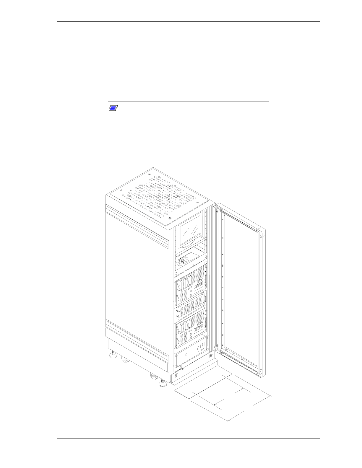
System Rack Placement
The system rack comes equipped with a front stabilizer that:
steadies the rack when you extend equipment for servicing, and
!
prevents creeping due to vibration.
!
The stabilizer is predrilled to allow you to secure the system rack to the floor.
Note:
If preparing the area prior to the arrival of the
system, review the power cable restrictions given in
“Electrical Facilities” before setting any stabilizer anchors.
Figure 2-2 gives the distance between anchoring holes when the stabilizer is
attached to the system rack.
17"
22"
Planning Your Site 2-7
Page 24
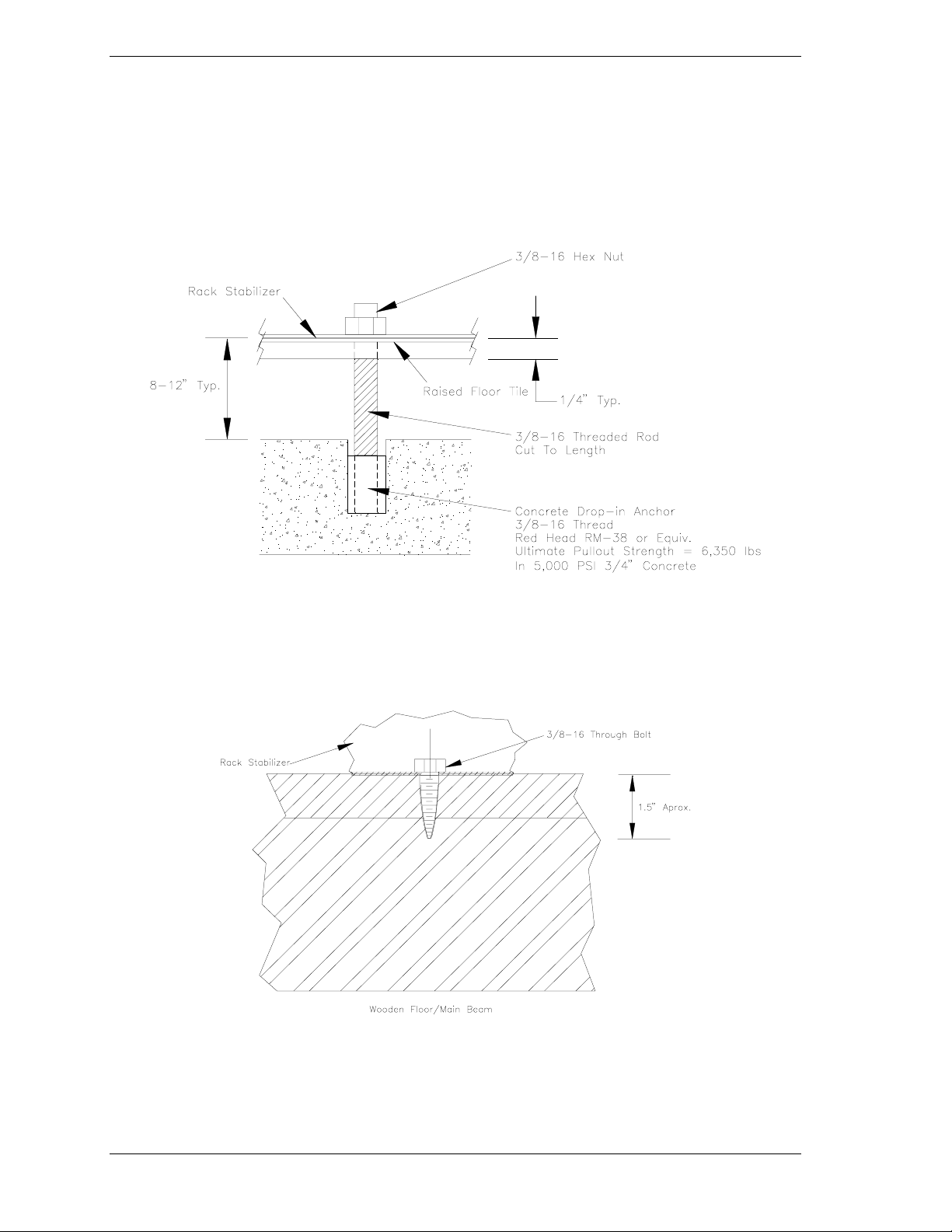
Figure 2-2. Distance Between Stabilizer Anchors
If the rack is installed on a concrete floor, you can bolt the rack to the floor
using 3/8" concrete drop-in anchors and 1½"-16 bolts.
If you are installing your rack in an area with a raised floor, you can use
concrete drop-in anchors and 3/8"-16 threaded rod with washers and nuts to
secure the rack to the concrete beneath the raised floor. See Figure 2-3.
Figure 2-3. Raised Floor Installation
When you are installing your system on a wooden floor, you can use 1-3/4" 3/8"
- 16 lag bolts as shown in Figure 2-4.
2-8 Planning Your Site
Figure 2-4. Wooden Floor Installation
Page 25

Air Conditioning
A properly sized air conditioning system ensures stable and reliable operation of
your servers by performing the following tasks:
cooling the system
!
preventing the generation of static charges
!
preventing the formation of corrosion causing condensation within the
!
system.
The system rack’s temperature and humidity requirements are listed in
Table 2-2.
Table 2-2. Temperature and Humidity Requirements
Item
Temperature 16 - 30°C 0 - 45°C
Relative humidity 40 - 70%
Temperature and humidity should be measured 19.5 inches (50cm) from the
system and 3.3 ft (1m) above the floor.
To satisfy temperature and humidity requirements, an air conditioner should be
capable of heating, humidifying, and dehumidifying.
Heat is needed to precisely control temperature, increase computer room
temperature in winter to the system’s operating conditions, and to control
humidity.
Humidifying is required to combat low humidity, which allows static charges to
build-up.
If the system is operated in high-humidity conditions where condensation can
occur, long term reliability may be affected.
Cooling Capacity
Operating Non-operating
10 - 80%
(non-condensing)
The cooling capacity of an air conditioner is determined by the following
factors:
90% of the total calorific value of the system (allowing for expansion)
!
calorific value from the ceiling, walls, and windows
!
calorific value generated by personnel
!
calorific value of lighting and additional machines
!
humidity control effects.
!
Planning Your Site 2-9
Page 26

The air conditioner’s capacity must be larger than the sum of the above items.
Use Table 2-3 to calculate calorific values – in BTUs.
Table 2-3. Calculating Total Calorific Values
Component BTU/hr Times Number
Basic System Unit (typical) 2048
Disk Expansion Unit (typical) 853
UPS 375
Monitor
8-Port Concentrator 410
Total
Electrical Facilities
Depending on whether data availability is critical to your application or not,
when you configured your system, you chose either an uninterruptible power
source or a power distribution unit to supply rack components with AC power.
The AC supply lines required by each of these devices is specified in the
following paragraphs.
Uninterruptible Power Source (UPS)
If you have purchased one or more UPSs to supply AC power to your system
and your system is located in North America, each UPS requires a 3-wire
30-Amp single-phase 120 Volt receptacle within six feet of the rear of the
system rack. The UPS power cord comes equipped with a NEMA L5-30P power
connector.
Equals
Installed
If your system is located in Europe, it requires a 240 Volt receptacle. The UPS
power cord comes equipped with an IEC-320-C20 power connector.
Power Distribution Unit (PDU)
If you have purchased one or more PDUs, each PDU requires a 3-wire 30-Amp
single-phase 120 Volt (240 Volt in Europe) receptacle within 10 feet of the rear
of the system rack. The UPS power cord comes equipped with a NEMA L5-30P
power connector (US models).
2-10 Planning Your Site
Page 27

Grounding Requirements
The system rack must have a dedicated ground attached to the power
distribution panel.
The ground wire must have an earth resistance of 100 ohms or less and
depending on your local electrical code, a thickness of 38 mm2 or more.
A grounding cable (12 gauge) that attaches the rack to frame (earth) ground
must be used.
For safety reasons, ground connections are necessary for both power distribution
systems and air conditioners.
If it happens that the ground to the server and the safety ground must be shared,
branch it near the grounding electrode.
If a building structure such as a steel frame is used as a grounding electrode, use
the main structural member closest to the building foundation.
Planning Your Site 2-11
Page 28

Page 29

Planning Your System Rack
Configuration
Cabling Constraints
!
Cable Summary
!
Vertical Spacing
!
Configuration Guidelines
!
Calculating Load and Determining UPS On-Battery
!
Run Time
3
Page 30

This chapter helps you configure your system and determine the number of
racks you will need for your system.
When planning your configuration, you should consider the following
guidelines:
Does the layout violate any cable constraints?
!
Is there enough rack space to accommodate all of the equipment that I
!
have?
Cabling Constraints
When planning your system configuration you must consider the length of the
cables that interconnect system components.
If a Server without any additional options meets all of your current computing
needs, you will only have to concern yourself with connections to your
keyboard, mouse, monitor and your LAN.
However, reviewing all the information in this section will allow you to
configure your rack with future expansion in mind.
Cable Summary
Table 3-1 summarizes the cables that provide power and interconnect system
components in the system rack. Additional information is provided in
subsequent paragraphs and in option installation guides.
Cable Purpose Length
UPS Power
Cable
UPS Smart
Cable(S)
PDU Power
Cable
Keyboard,
Mouse and
Monitor Cables
Connects main AC power to your UPS. 6 feet (1.8 meters)
These cables connect your UPS – via Smart-UPS
cables – to a master server running PowerChute
software and two
plus
Working together, these options execute a controlled,
orderly shutdown of all connected Servers.
If you did not purchase an UPS, this cable connects
main AC power to your Power Distribution Unit
(PDU).
Connects your keyboard, mouse, and monitor to
your:
BSU or concentrator, and each BSU keyboard,
mouse, and monitor port to your concentrator.
Table 3-1. Cable Summary
protected
BSUs.
®
®
6 feet (1.8 meters)
15 feet (4.57 meters)
7 or 12 feet (2.13 or
3.65 meters)
depending on option
chosen
Extension
Cables
SCSI Bus
Cables
You can use 12-foot extension cables to extend
connections from your 8-port concentrator to your
keyboard, mouse, and monitor.
Connects RAID Controllers to DEUs Vendor specific
3-2 Planning Your System Rack Configuration
12 feet
(3.65 meters)
Page 31

RAID Cable Restrictions
RAID Host Adapters use a SCSI cable that connects each Disk Expansion Unit
to its RAID Host Adapter in the Basic System Unit. Cables are available in
3.3-ft (1m) and 9.9-ft (3m) lengths.
Concentrator Cable Lengths
Cables for concentrator connections are available in 7-ft (2.1m) and 12-ft
(3.7m) lengths.
To accommodate the installation of the keyboard, mouse, and monitor on an
external desktop, a 12-ft (3.7m) extension cable that allows you to achieve an
overall cable length of 19-ft (5.8m) or 23-ft (7.3m) is available.
NOTE: Extension cables should only be used between the keyboard, mouse,
and monitor and the concentrator. They cannot be used between the concentrator
and a BSU.
Vertical Spacing
Vertical measurements of rack components are given in Us. 1U is equal to 1.75
inches.
The total usable vertical space within a 42U rack is 42Us or 73.5 inches.
Figure 3-1 illustrates the arrangement of rack mounting holes and their
relationship to a U.
Planning Your System Rack Configuration 3-3
Page 32

Figure 3-1. Mounting Hole Arrangement within a Rack
3-4 Planning Your System Rack Configuration
Page 33

Table 3-2 lists the vertical space requirements for several Express5800 Server
models and other rack components.
Table 3-2. Vertical Space Requirements
Rack Components Space Requirements
(Approximate)
Express5800/120Ld 5U 8.75” (22.23cm)
Express5800/120Mc2 6U 10.5” (26.67cm)
Express5800/120Mc3 7U 12.25” (31.12cm)
Express5800/180Ra-7 7U 12.25” (31.12cm)
Express5800 ES1400 5U 8.75” (22.23cm)
Express5800 HX4500 14U 24.5” (62.23cm)
Express5800 HX4600 14U 24.5” (62.23cm)
Express5800 HV8600 17U 29.75” (75.57cm)
Express5800 LC1400 6U 10.5” (26.67cm)
Express5800 LS2400 5U 8.75” (22.23cm)
Express5800 MC2200 7U 10.5” (26.67cm)
Express5800 MC2400 6U 10.5” (26.67cm)
Express5800 MH4500 7U 12.25” (31.12cm)
Uninterruptible Power Source 3U 5.25" (13.12cm)
Power Distribution Unit
Disk Expansion Unit 3U 8.9" (22.2cm)
14" and 15" monitor with tray 10U 17.5" (43.75cm)
17" monitor with tray 11U 19.25" (27.5cm)
Keyboard and mouse with tray 2U 3.5" (8.75cm)
Concentrator 1U 1.75" (4.37cm)
1U blank panel 1U 1.75" (4.37cm)
2U blank panel 2U 3.5" (8.75cm)
3U blank panel 3U 5.25" (13.12cm)
6U blank panel 6U 8.72" (22.2cm)
*The Power Distribution Unit may be installed behind filler panels, the monitor tray or the
keyboard tray.
*
2U 3.5" (8.75cm)
Planning Your System Rack Configuration 3-5
Page 34

Configuration Guidelines
When you configure a system, you should check your configuration to ensure
compliance with the following guidelines:
1.
To improve rack stability when servicing system components, mount heavier
items such as servers in the bottom of the rack. If your rack is a stand-alone
unit and the rack is more than 75% filled with components, consider
installing the optional side stabilizer kit.
2.
Each Model 42U Rack can contain up to 42U of components (1U is equal to
1.75 inches). Models 36U and 27U contain up to 36U and 27U of
components, respectively.
3.
The maximum Volt/Amps available from a single UPS is 3000VA (2250W).
4.
The maximum Volt/Amps available from a single PDU is 2880VA.
5.
The UPS should always be installed in the bottom of the rack.
6.
The UPS and its associated PowerChute® plus software can only support
three servers per UPS, without purchasing an additional interface expander
module and additional cables.
7.
If power distribution is provided by a PDU, the PDU is normally installed in
the bottom of the rack. However, when rack space is at a premium, you can
install the PDU directly behind the keyboard tray or the monitor tray.
8.
The keyboard can be no more than 5U from the BSU unless a concentrator
or extension cables are purchased.
9.
If you are configuring the keyboard for use in a standing position, the
recommended height is 18 to 20 U.
The System Rack Configuration Worksheet, Table 3-3, may be used to calculate
the space requirements for components you plan on installing into the rack.
3-6 Planning Your System Rack Configuration
Page 35

Table 3-3. System Rack Configuration Worksheet
Inches Us Component Notes
73.5 42
71.75 41
70 40
68.25 39
66.5 38
64.75 37
63 36
61.25 35
59.5 34
57.75 33
56 32
54.25 31
52.5 30
50.75 29
49 28
47.25 27
45.5 26
43.75 25
42 24
40.25 23
38.5 22
36.75 21
35 20
33.25 19
31.5 18
29.75 17
28 16
26.25 15
24.5 14
22.75 13
21 12
19.25 11
17.5 10
15.75 9
14 8
12.25 7
10.5 6
8.75 5
74
5.25 3
3.5 2
1.75 1
Planning Your System Rack Configuration 3-7
Page 36

Calculating Load and Determining UPS On-Battery Run Time
When you have chosen your configuration, you can use Table 3-4 and Table 3-5
to determine the load on a single power source and how much run time your
configuration can expect from your UPS in the event your main AC service is
interrupted.
To calculate the load and your on-battery run time, perform the following steps:
1.
Determine the total load placed on each power source. The maximum load
you can place on a single power source is:
Source Maximum Load
UPS 3000VA (2250W)
PDU 2880VA
Table 3-4 provides Volt/Amp load values of system components and
provides space to include other options.
You can calculate Volt/Amps by multiplying a component’s voltage by its
current requirement.
Voltage * Amps = VA
Or if your component’s power requirement is expressed in watts, multiply its
wattage rating by 1.4.
Watts * 1.4 = VA
3-8 Planning Your System Rack Configuration
Page 37

Table 3-4. Determining the Load on a Single Power Source
Component Voltage Amps# VA
Express5800/120Ld 120 4.6 552
Express5800/120Mc2 120 9.0 1080
Express5800/120Mc3 120 9.0 1080
Times the
Number of
Systems
Installed
Load
Express5800/180Ra-7*
Express5800/180Ra-7**
Express5800 ES1400 120 6.0 720
Express5800 HX4500 120 12.0 1440
Express5800 HX4600 120 10.5 1260
Express5800 HV8600 120 10.0 1200
Express5800 LC1400 120 9.0 1080
Express5800 LS2400 120 6.0 720
Express5800 MC2200 120 9.0 1080
Express5800 MC2400 120 9.0 1080
Express5800 MH4500 120 10 1200
3UDEU
Port Concentrator 100 1 100
Monitor
120 5.1
8.5
612
1020
Other
Other
Other
* 4 Processors Installed
** 8 Processors Installed
# Absolute Maximum Ratings
2.
Add the individual loads you have listed in Table 3-4 to determine the total
load on the power source.
3.
To determine the run time your UPS will provide your system during a
power failure, use Table 3-5 to find your total load and its associated run
time in minutes.
Planning Your System Rack Configuration 3-9
Page 38

Table 3-5. Total Load Versus On-Battery Run Time
Total Load
50VA 297 600VA 54
75VA 258 700VA 44
100VA 228 800VA 36
150VA 183 900VA 31
200VA 152 1000VA 26
250VA 128 1200VA 20
300VA 110 1400VA 16
350VA 96 1600VA 13
400VA 84 2000VA 10
450VA 75 2200VA 8
500VA 67 2500VA 7
550VA 60 3000VA 5
Run Time in
Minutes
Total Load
Run Time in
Minutes
3-10 Planning Your System Rack Configuration
Page 39

Installing the System Rack
Introduction
!
Unpacking the System Rack and Components
!
Leveling the System Rack
!
Installing Rack Frame Link Kits
!
Attaching the Stabilizer to the System Rack
!
4
Page 40

Introduction
The steps required to prepare your rack are:
Unpack and inventory your rack and its system components.
!
Remove the doors and side panels from the rack to simplify the assembly
!
of rack components.
Position and level the rack(s).
!
Install one or more rack frame link kits when assembling multi-rack
!
systems.
Attach the front stabilizer when your rack is in its permanent location.
!
What You Need
In addition to the materials shipped to you and standard hand tools, you will
need:
a level for leveling the rack and an adjustable wrench to lower and secure
!
the leveling feet
an adjustable wrench or ratchet set to attach the stabilizer to the base of
!
the rack
a #2 and #3 Phillips-head screwdriver to assemble rack-mounting
!
hardware, and
if you are assembling a multi-rack system, you will need a six foot step-
!
ladder
!
WARNING
It is strongly recommended that two people be present when
assembling the rack and installing system components.
4-2 Installing the System Rack
Page 41

Unpacking the System Rack and Components
Carefully unpack and verify the contents of each shipping carton. Be sure that
you have all the hardware components and documentation.
In addition to this guide, you also received installation guides for options that
were ordered. Your Server User’s Guide contains information on installing your
server into the rack.
Note:
It is important to save this documentation. It
contains information that is valuable to both Field Service
personnel and System Administrators. For example, the
UPS Rack Mount Supplement describes how to replace and
recycle the UPS battery.
If you find anything damaged or missing, contact your local service
representative.
Your rack is shipped on a wooden pallet that includes an off-loading ramp. The
rack is covered with corrugated cardboard and secured by plastic banding. See
Figure 4-1
To remove the rack from the pallet, perform these steps:
1.
Cut the banding and remove the corrugated cardboard.
2.
Lower the off-loading ramp.
!
WARNING
The weight of an empty system rack is 253 lbs. If you are not
using professional riggers to place the rack in its permanent
location, do not attempt to remove the rack from the pallet
without adequate assistance.
3.
Roll the rack down the ramp to its permanent position.
Installing the System Rack 4-3
Page 42

Figure 4-1. Rack Mounted on Shipping Pallet
4-4 Installing the System Rack
Page 43

Opening Front and Rear Doors
The front and rear doors of the rack are secured by handles with keylocks. To
open the door:
1.
Slide the handle release cover up to uncover the keylock and the handle
release button. See Figure 4-2, A.
2.
Unlock the lock, if necessary (Figure 4-2, B). Depress the handle release
button (key hole button). The door handle extends when unlatched.
3.
Rotate the handle (Figure 4-2, C) clockwise to open the door.
A
B
C
Figure 4-2. Accessing Door Handles
Inside the base of the rack, you will find a generous supply of mounting
hardware – self-tapping screws, plated finish screws, black plastic washers and
M6 cage-nuts.
You can simplify the removal of the rack from the pallet as well as the system
assembly process by removing the front and rear doors and dismantling the side
panels.
Installing the System Rack 4-5
Page 44

If you are installing a multi-rack system you must remove adjacent side panels
of racks prior to installing the rack frame link kit.
Removing Rack Side Panels
To remove the rack side panels:
1.
Remove the eight Phillips-head screws securing each side panel to the rack.
See Figure 4-3.
2.
Lift the side panels out and away from the rack.
Figure 4-3. Removing the Side Panels.
4-6 Installing the System Rack
Page 45

Leveling the System Rack
When the rack is removed from the pallet and placed in its permanent location,
you will extend the lifecycle of mechanical components by leveling the your
rack.
Before leveling the rack, position the rack to conform with the space
requirements specified in Chapter 2 and verify that your power receptacle is
within six feet of the rear of your rack. To level the rack:
1.
Lower the leveling foot located in each corner of the rack until they all make
contact with the floor. See Figure 4-4
Figure 4-4. Leveling Foot Adjustment
2.
Using your level, check the vertical and horizontal planes of the rack for
level. Level your system rack by turning the adjusting nut on the top of each
foot as needed.
3.
Secure each leveling foot by tightening the lock nut up against the
underside of the rack.
Installing the System Rack 4-7
Page 46

Installing Rack Frame Link Kits
This section describes how to assemble two or more racks into a multi-bayed
system using the rack frame link kit. Figure 4-5 shows a linked multi-bayed
system.
What You Need
In addition to the Rack Frame Link shown in Figure 4-6, you will need:
a #2 and #3 Phillips-head screwdriver to assemble the kit
!
a six foot step-ladder
!
It is strongly recommended that two people be present when
assembling the rack and installing system components.
Figure 4-5. Multi-Bayed Rack System
Figure 4-6. Rack Frame Link Kit
!
WARNING
4-8 Installing the System Rack
Page 47

To install the rack frame link kit:
1.
Position the two rack cabinets next to each other as shown in Figure 4-7.
Ensure the front of each rack is facing in the same direction.
2.
Position a link angle bracket in the upper front corner of the left cabinet and
secure it to the cabinet with two Phillips-head screws. See Figure 4-7.
3.
Secure the remaining three link angle brackets to the other three corners of
the left cabinet in the same manner.
4.
Move the right cabinet adjacent to the left cabinet so that the link angle
brackets secured to the left cabinet protrude into the corners of the right
cabinet.
5.
Secure the cabinets together with the Phillips-head screws supplied.
Front
Front
Figure 4-7. Rack Frame Link Kit Installation
Installing the System Rack 4-9
Page 48
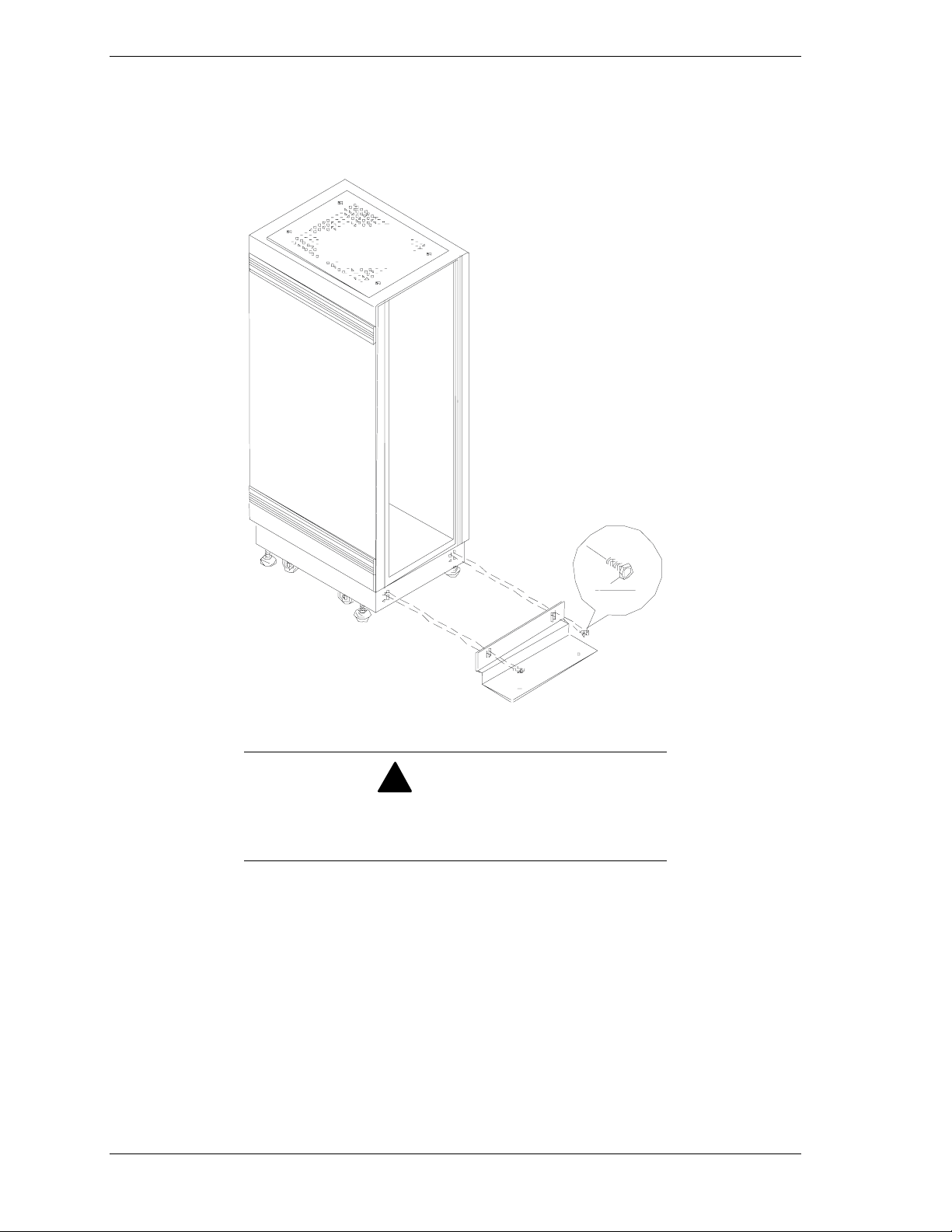
Attaching the Stabilizer to the System Rack
After positioning and leveling the system rack, attach the stabilizer to the front
of your rack using an adjustable wrench or ratchet. See Figure 4-8.
Figure 4-8. Attaching the Front Stabilizers
To ensure the stability of the rack during component
installation, you must attach the front stabilizer prior to
installing any system components.
If you are securing the rack to the floor, do so now. See Chapter 2 – “Securing
the System Rack” for details.
4-10 Installing the System Rack
!
WARNING
Page 49

Installing Rack Components
Tools Required
!
Installing Rack Components
!
Installing the UPS
!
Installing a Power Distribution Unit
!
Installing a Keyboard Tray
!
Installing the Concentrator
!
Installing Blank Panels
!
Installing a Monitor Tray
!
5
Connecting the Console Monitor
!
Connecting Servers to the Concentrator
!
Installing Other System Rack Components
!
Page 50

This chapter describes the installation of individual system components in a
system rack. For the purpose of explanation, installation instructions are
presented in the order required to install a typical configuration. See Table 5-1
Table 5-1. Typical Configuration
Inch Us System Rack Notes
73.5 42
71.75 41
70 40
68.25 39 11U of space remains to
66.5 38 accommodate up to a
64.75 37 17 inch monitor.
63 36
61.25 35
59.5 34
57.75 33
56 32
54.25 31 1U monitor tray
52.5 30
50.75 29
49 28 6U blank panel
47.25 27
45.5 26
43.75 25
42 24
40.25 23 3U blank panel
38.5 22
36.75 21 1U port concentrator
35 20 2U keyboard tray
33.25 19
31.5 18 2U blank panel
29.75 17
28 16
26.25 15 3U blank panel
24.5 14
22.75 13
21 12
19.25 11 7U
17.5 10 Basic System Unit
15.75 9
14 8
12.25 7
10.5 6
8.75 5 3U Disk Expansion Unit
74
5.25 3 3U Uninterruptible
3.5 2 Power
1.75 1 Source
The exception to this process is the Power Distribution Unit (PDU), which is
discussed as an alternative to the UPS that it immediately follows.
5-2 Installing Rack Components
Page 51

Tools Required
In addition to the materials shipped to you and standard hand tools, you will
need:
#2 and #3 Phillips-head screwdrivers to assemble rack-mounting
!
hardware, and
a 3mm Allen wrench and 4mm nut driver to tighten the monitor tray
!
mounting posts
Installing Rack Components
In general, the installation of a rack unit requires the:
Installation of cage-nuts at the rail locations used to secure the front
!
bezel of a unit to the rack. Figure 5-1 shows a typical installation of the
cage-nuts.
Installation of mounting hardware, usually chassis slide rails or
!
L-brackets
Installation of the unit into its mounting hardware and then securing the
!
unit to the rack
Connection of AC power and data cables
!
Note:
If using this document for an upgrade of existing
equipment, be sure that all external cables connected to the
system unit are disconnected before sliding the unit out from
the rack.
Figure 5-1. Installing Rack Hardware
Installing Rack Components 5-3
Page 52

Recommendations and Warnings
Please adhere to the following recommendations and warnings when installing
your rack system.
To improve rack stability when servicing system components, mount
!
heavier items such as a UPS or server in the bottom of the rack.
If your rack is a stand-alone unit and the rack is more than 75% filled
!
with components, consider installing the optional side stabilizer kit.
Refer to Table 6-2 for the part number of the side stabilization kit.
!
WARNING
Two people are required when assembling the rack and
installing system components into the rack.
Installing the UPS
This section describes how to install an Uninterruptible Power Source (UPS)
into a system rack. See Figure 5-2.
The Uninterruptible Power Source (UPS) is a high-performance, line-interactive
supply that provides clean, reliable AC power to system rack components to
protect them from power blackouts, brownouts, swells, sags, surges, and
interference.
Figure 5-2. Uninterruptible Power Source
5-4 Installing Rack Components
Page 53

Your UPS provides diagnostic and management features that include:
Scheduled server shutdowns
!
Interactive and scheduled battery testing
!
Detailed power quality logging
!
Real-time graphical displays showing
!
UPS load
utility line voltage
battery voltage
run time remaining
These features are implemented for a single server (BSU) by connecting the
server’s serial port to the UPS computer interface port and installing the
PowerChute® plus software on the server (BSU).
The System Administrator uses the PowerChute® plus graphical user interface to
set up the operational parameters required by site policies.
Additional servers installed in the same rack may be connected to the UPS
when:
You install the Smart Slot™ UPS Interface Expander Unit into the UPS.
!
You connect the protected server’s serial port to the expander accessory
!
unit using the simple signaling cables received with the Expander Unit
Interface Kit.
The System Administrator installs PowerChute® Plus software on each
!
protected server and uses the graphical user interface to set up the
operational parameters required by site policies.
Figure 5-8 illustrates the connections between the UPS, master server, and
additional protected servers.
This procedure summarizes the installation of a UPS in a system rack. For
detailed information about:
UPS Refer to:
Features Uninterruptible Power Source User’s Manual
UPS Interface Expander Unit Interface Expander Unit User’s Manual
Installation This Rack User’s Manual
Expander Unit Interface Kit Interface Kit User’s Manual
®
PowerChute
plus
PowerChute®
User’s Guide
plus
Installing Rack Components 5-5
Page 54

Installing the Interface Expander Accessory
You can install the interface expander unit prior to installing the UPS in the
rack.
Note:
Perform this procedure if you are connecting more
than one server (BSU) to the UPS.
To install the interface expander, perform the following steps:
1.
Using a #2 Phillips-head screwdriver, remove the two screws securing the
top accessory slot cover on the back panel of the UPS. See Figure 5-3.
Retain the screws for future use.
Figure 5-3. Accessory Slot Location
2.
Position the interface expander unit to fit in the UPS accessory slot as shown
in Figure 5-4.
A
Figure 5-4. Installing the Interface Expander
5-6 Installing Rack Components
Page 55

3.
Slide the interface expander all the way into the slot, until the end plate is
flush with the back panel of the UPS.
4.
Secure the accessory with the two screws removed in Step 1.
5.
If the installation does not include PowerChute® plus software, review the
following topics with the System Administrator:
Configuration switch settings (Figure 5-4, A); see Section 7 of the UPS
!
Interface Expander Accessory document, and
Status Light; see Section 10 of the UPS Interface Expander Accessory
!
document.
software overrides UPS configuration switch settings.
Installing the UPS
To install the UPS:
1.
Install the four M6 cage-nuts that will secure the front of the UPS to the
rack. Position the cage-nuts to align with the screw holes in the front bezel
of the UPS. Use the template provided with the UPS.
Note:
When installed and configured, PowerChute
A
®
plus
Figure 5-5. Installing M6 Cage-Nuts
2.
As illustrated in Figure 5-6, assemble the L-channel support brackets (A)
and adjust the rails to span the depth of the rack.
Installing Rack Components 5-7
Page 56

A
C
B
Figure 5-6. Mounting UPS L-Channel Supports
3.
Secure the brackets to the rails with the washers and flat-head screws
(Figure 5-6, C) provided with the UPS.
Note:
The ear of an L-channel support has two mounting
screw holes.
4.
With the aid of another person, slide the UPS onto the L-channel supports
and secure the UPS to the rack using the black plastic washers and plated
finish screws provided with the rack.
5.
Connect the UPS battery. Refer to the documentation that you received with
the UPS for details.
6.
Connect the UPS power cable to the AC power source. Refer the
documentation provided with your UPS.
7.
Switch on the UPS to execute a self-test before connecting any system
components. See the Installation and Operation section of the
“Uninterruptible Power Source User’s Manual”.
8.
Check the Site Wiring Fault indicator. See Figure 5-7, C.
If the indicator is illuminated, have a qualified electrician correct the
building wiring. Faults can be caused by a missing ground, a hot and
neutral polarity reversal, or an overloaded neutral circuit.
5-8 Installing Rack Components
Page 57

B
A
D
C
A. Basic Monitoring Port 1
B. Basic Monitoring Port 2
C. Site Wiring Fault Indicator
D. Configuration Button
I
H
G
F
E
E. Configuration LED
F. Smart Monitoring Port for Master Server
G. Configuration Switches
H. Status Light
I. Output Power Receptacles
Figure 5-7. Location of UPS Rear Panel Components
9.
If you do not have a wiring fault, connect the ground lead of any transient
voltage surge-suppression (TVSS) devices such as telephone and network
line protectors. The TVSS connector provides grounding through the UPS’
power cord ground conductor. This provides protection from damage from
surges transmitted via network and phone cables.
Installing Rack Components 5-9
Page 58

Connecting Your Master and Protected servers (BSUs)
To connect your master and protected servers, perform the following steps:
1.
As the installation progresses, connect the power cables from individual
system components to the receptacles of the AC distribution panel located in
the rear of the UPS. See Figure 5-8, F.
2.
Designate one server to be your master server and connect the black smart
signaling cable (Figure 5-8, C) received with the PowerChute® plus option,
between a server serial port and the UPS smart signaling port.
3.
On your configuration worksheet, note which server and serial port are
connected as master. The System Administrator will need this information
when loading and configuring PowerChute® plus software.
4.
Using the gray simple signaling cable (Figure 5-8, A) from the interface kit,
connect the server(s) being protected to the basic monitoring ports 1 and 2 of
the interface expander accessory.
5.
On your configuration worksheet, identify each protected server and its
connection to the basic monitoring ports.
6.
Deliver the configuration worksheet to the System Administrator. This
information is required to properly configure PowerChute® plus software.
5-10 Installing Rack Components
Page 59

A
F
C
D
B
A. Simple Signal Cables (Gray Cables)
B. Master Server (BSU)
C. Smart Cable (Black Cable)
D. Protected Server (BSU) 1
E. Protected Server (BSU) 2
F. AC Distribution Panel
Figure 5-8. Connecting Your Servers to the UPS
E
Installing Rack Components 5-11
Page 60

Installing a Power Distribution Unit
If you are not using an Uninterruptible Power Source (UPS), AC power is
distributed to system components through a Power Distribution Unit (PDU). See
Figure 5-9.
The PDU comes equipped with a 15-foot power cord and can be installed either
in the bottom of the rack, or when rack space is at a premium, directly behind
your keyboard tray. See your configuration work sheet to determine the location
chosen for your PDU.
Note:
When you install a PDU behind a keyboard tray,
the remaining workspace will be restricted. Therefore, it is
recommended that keyboard, mouse, monitor, and
connections to any port concentrator are completed before
you install a PDU behind a keyboard tray.
D
A
E
B
C
A. Cage-nut
B. Rack Vertical Rail, Left Rear
C. PDU Mounting Screw and Washer
D. Green Ground Strap
E. Rack Vertical Rail, Right Rear
Figure 5-9. Installing the Power Distribution Unit
5-12 Installing Rack Components
Page 61

To install your PDU:
1.
Place two cage-nuts (Figure 5-9,A) on each rail at the location you have
chosen to mount your PDU.
2.
Secure the PDU to the rails using the black plastic washers and plated-finish
screws (Figure 5-9, C).
3.
Using a self-tapping screw, connect the green ground strap
(Figure 5-9, D) to the rail.
4.
Connect the AC power cord to the PDU.
5.
If you install your PDU behind the keyboard tray, midway up the rack rather
than in the bottom of the rack, dress and secure the power cable to provide
some strain relief to the cable connection.
Installing a Keyboard Tray
Note:
Some keyboard tray models are front-mount only,
and are secured only to the front rails. Your keyboard tray
may not look like the model pictured in Figure 5-10.
This section describes how to install a keyboard tray into a system rack.
The keyboard tray provides you with:
a convenient work surface that stores your keyboard and mouse
!
a secured compact enclosure when your keyboard and mouse are not in
!
use
Front Rail
Rear Rails
A
B
C
Figure 5-10. Securing the Keyboard Tray
Installing Rack Components 5-13
Page 62

As shown in Figure 5-10, the keyboard tray is secured to the front and rear rails
of the system rack in with cage-nuts, black plastic washers, and plated finish
screws that came with the system rack.
To install your keyboard tray:
1.
Using the longer set of screws (Figure 5-10, A) received with the keyboard
tray, attach the two halves of each side rail together. The rear rail (Figure
5-10, B) should be assembled to the outside, or closest to the rack rails.
2.
Adjust the length of the keyboard tray rails to fit between the front and rear
vertical posts in the system rack.
3.
Place two cage-nuts (Figure 5-10, C) on each front and rear rail at the
locations you have chosen to mount your keyboard tray.
4.
Secure the keyboard tray to the rails using the black plastic washers and
plated-finish screws.
Installing the Concentrator
This section describes how to install a concentrator into a system rack.
A concentrator allows you to use a single keyboard, mouse, and video display as
a console monitor for up to eight servers (BSUs).
You can install your console monitor either in your system rack or externally on
a desktop. Cables for the concentrator connections are available in 7-ft and 12-ft
lengths.
A 12-ft extension cable allows you to achieve an overall cable length of 19-ft or
24-ft in order to install the keyboard, mouse, and monitor on an external
desktop.
Note:
Extension cables should only be used between the
keyboard, mouse, monitor and the concentrator.
5-14 Installing Rack Components
Page 63

To install your concentrator:
3.
Using the longer set of screws (Figure 5-11, C) received with the
concentrator, attach the two halves of the side rail together. The rear rail
(Figure 5-11, B) should be assembled to the outside, or closest to the rack
rails.
A
C
B
A. Concentrator
B. Rear Concentrator Rail
E
D
C. Concentrator Rail Screws
D. Concentrator Mounting Screws
E. Front Concentrator Rail
Figure 5-11. Assembling the Concentrator Rails
4.
Adjust the length of the concentrator rails to fit between the outside of the
front and rear vertical posts in the system rack.
5.
Attach the two side rails to the sides of the concentrator with the four shorter
screws (Figure 5-11, D) received with the concentrator.
Installing Rack Components 5-15
Page 64

4.
Install the supporting cage-nuts in the rail. See Figure 5-12.
Figure 5-12. Installing the Port Concentrator
5.
Attach the side rails and concentrator to the system rack with plated finish
screws and washers that you received with the system rack.
Note:
The concentrator connector panel should face the
rear of the system rack and the blank panel should face the
front of the system rack.
5-16 Installing Rack Components
Page 65

Installing Blank Panels
This section describes how to install blank filler panels on the front of your
system rack to give your rack a finished look.
Blank filler panels are available in the following sizes:
1U (1.75")
!
2U (3.5")
!
3U (5.25")
!
6U (10.5").
!
As shown in Figure 5-13, blank panels are attached to the front of the system
rack with cage-nuts, black plastic washers, and the Phillips-head screws, that
you received with the system rack.
Left Front
Figure 5-13. Installing a 1U Filler Panel
Right Front
Installing Rack Components 5-17
Page 66

Installing a Monitor Tray
This section describes how to install a monitor tray into a system rack. The
monitor tray provides a convenient work surface for your video monitor.
Perform the following steps to attach your monitor tray:
1.
Determine the location for the monitor tray.
2.
Install the four M6 cage-nuts that will secure the front of the monitor tray to
the front rack rails. Position the cage-nuts to align with the screw holes in
the front of the tray. See Figure 5-14, A.
Front Rail
Rear Rails
A
B
Figure 5-14. Monitor Tray and Mounting Hardware
3.
Position the monitor tray inside the rack and secure the monitor tray to the
rails using the black plastic washers and 3 plated-finish screws.
5-18 Installing Rack Components
Page 67

Connecting the Console Monitor
Perform the following steps to connect the console monitor to the concentrator.
1.
The keyboard, mouse, and video display cables attach to the first group of
connectors on the left of the concentrator when viewed from the rear. See
Figure 5-15.
2.
The top-most connector is for the monitor (Figure 5-15, A). Below the
monitor connector, connect the keyboard to the keyboard connector (K) and
connect the mouse to the mouse connector (M).
Note:
If necessary, you can use 12-ft extension cables to
achieve overall cable lengths of 19-ft or 24-ft to
accommodate the placement of your console monitor on
external desktop.
One Two Three Four Five Six Seven Eight
A
One
Reset
M
K
Figure 5-15. Connecting Cables to the Port Concentrator
M
K
Connecting Servers (BSUs) to the Concentrator
1.
Connect the keyboard, mouse, and video display cable from each server to
one of the concentrator connector groups labeled one through eight. See
Figure 5-15.
2.
Attach the AC power cord to the receptacle located next to the power on/off
switch on the right side of the concentrator when viewed from the rear.
Connect the other end of this power cord to the PDU or UPS.
Installing Rack Components 5-19
Page 68

Page 69

Illustrated Parts Breakdown
Field Replaceable Units
!
Options
!
6
Page 70

This chapter helps you identify the Field Replaceable Units (FRUs) for the rack
assembly. A list of available options for a rack system is also included in this
chapter.
Figure 6-1 illustrates the 42U Rack and includes numbered callouts that refer to
the reference numbers listed in Table 6-1. Table 6-1 lists the part numbers for all
rack assembly FRUs.
1
17
16
15
19
18
14
13
12
2
Front View
3
Rear
4
5
6
Front
7
8
Side View
20
21
Figure 6-1. Field Replaceable Unit Locations
6-2 Illustrated Parts Breakdown
9
10
11
Rear View
Page 71

Field Replaceable Units
Table 6-1 lists the Field Replaceable Units for the three rack models. Unless
otherwise noted part numbers shown are for use in the United States and
Europe.
Table 6-1. Field Replaceable Units
42U Rack Enclosure
Reference
Description
Number
1 Roof, Perforated 247-01652-000 247-01652-000 247-01652-000
2 Door, Front,
Includes handle
and lock insert
3 Door, Front
Handle
4 Keylock Insert 247-01631-000 247-01631-000 247-01631-000
5 Rail, Front or rear
vertical 19”
6 Rail, System
chassis vertical
7 Rail, System
chassis horizontal
8 Rail, System
chassis vertical
9 Door, Rear 247-01629-000 247-01643-000 247-01649-000
10 Cross Mullion 247-01633-000 247-01633-000 247-01633-000
(AZA-4200) 2000mm
x 600mm x 1000mm
247-01628-000 247-01629-000 247-01648-000
247-01630-000 247-01630-000 247-01630-000
247-01638-000 247-01645-000 247-01651-000
247-01639-000
(900mm)
247-01639-000
(900mm)
247-01640-000
(500mm)
36U Rack Enclosure
(AZA-3600) 1800mm
x 600mm x 1000mm
247-01646-000
(700mm)
247-01639-000
(900mm)
247-01640-000
(500mm)
27U Rack Enclosure
(AZA-2700) 1400mm
x 600mm x 1000mm
247-01640-000
(500mm)
247-01639-000
(900mm)
247-01647-000
(300mm)
11 Panel, Solid
partial
12 Stabilizer, Front 247-01642-000 247-01642-000 247-01642-000
13 Base, Mobile 247-01635-000 247-01635-000 247-01635-000
14 Foot, Leveling 247-01637-000 247-01637-000 247-01637-000
15 Castor, 80mm
swivel
16 UPS, Rackmount
3000VA 3U
17 Panel, Side 247-01634-000 247-01644-000 247-01650-000
18 Kit
Keyboard/Mouse
Tray
19 Rittal Monitor Tray
Kit
20 Nuts, Captive 250-01510-000 250-01510-000 250-01510-000
247-01632-000 247-01632-000 247-01632-000
247-01636-000 247-01636-000 247-01636-000
148435-01 148435-01 148435-01
050-01628-000 050-01628-000 050-01628-000
050-01636-000 050-01636-000 050-01636-000
Illustrated Parts Breakdown 6-3
Page 72

Table 6-1. Field Replaceable Units (Continued)
42U Rack Enclosure
Reference
Description
Number
21 Rack Frame Link 050-01627-000 050-01627-000 050-01627-000
Figure 5-11 8-port
Concentrator
Figure 5-11 8-port
Concentrator
Rack Mount Kit
Figure 5-9 Power Distribution
Unit, 120v,
PT3500
Rackmount
Figure 5-11 UPS Interface
Expander
Figure 5-13 1u Blank Filler
Panel Kit M/W
2u Blank Filler
Panel Kit M/W
3u Blank Filler
Panel Kit M/W
(AZA-4200) 2000mm
x 600mm x 1000mm
6758130000 6758130000 6758130000
1451960000 1451960000 1451960000
149068 149068 149068
149576 149576 149576
050-01632-000 050-01632-000 050-01632-000
050-01630-000 050-01630-000 050-01630-000
050-01625-000 050-01625-000 050-01625-000
36U Rack Enclosure
(AZA-3600) 1800mm
x 600mm x 1000mm
27U Rack Enclosure
(AZA-2700) 1400mm
x 600mm x 1000mm
6u Blank Filler
Panel Kit M/W
Rittal Side
Stabilizer
Server Cable
Simple For UPS
Cable Set, 12’
Mouse/Video/Key
board Extension
Cable Set,
Switchbox, 12
Foot, Server To
SW
Cable Set,
Switchbox, 7
Foot, Server To
SW
Bracket,
Combination
Screws, Phillips 250-01509-000 250-01509-000 250-01509-000
050-01626-000 050-01626-000 050-01626-000
6774270000 6774270000 6774270000
070541 070541 070541
0705390000 0705390000 0705390000
0706310000 0706310000 0706310000
0705380000 0705380000 0705380000
247-01641-000 247-01641-000 247-01641-000
6-4 Illustrated Parts Breakdown
Page 73

Options
Table 6-2 lists the options available for your rack assembly. Contact your local
representative for more information.
Part Number Description
ACN-0011-00-00 Cable Set, 12’ Mouse/Video/Keyboard Extension
ACN-0010-00-00 Cable Set, Switchbox, 12 Foot, Server To SW
ACN-0009-00-00 Cable Set, Switchbox, 7 Foot, Server To SW
AEX-8000-00-US 8-Port Switchbox For Servers
AZA-4001-00-00 Rack Frame Link Kit (links two racks together)
AZA-4002-00-00 1U Blank Filler Panel Kit M/W
AZA-4003-00-00 2U Blank Filler Panel Kit M/W
AZA-4004-00-00 3U Blank Filler Panel Kit M/W
AZA-4005-00-00 6U Blank Filler Panel Kit M/W
AZA-4006-00-00 Front Mount Monitor Tray Kit
AZA-4007-00-00 Keyboard/Mouse Tray Kit
Table 6-2. Options
AZA-3007-00-00 Non Swivel Keyboard Tray
AIB-0080-00-00 Slim Keyboard
AZA-4008-00-00 Side Stabilizer Kit (two side stabilizers)
ASP-0001-00-US Power Strip,120v Pt3500 (PDU)
ABA-3000-00-US Rack-mount 3000VA 3U RM (UPS)
Illustrated Parts Breakdown 6-5
Page 74

Page 75

Index
A
Air Conditioning, 2-9
cooling capacity, 2-9
B
Blank Panels
installing, 5-17
C
Cable Restrictions
RAID, 3-3
Cable Summary, 3-2
Cabling Constraints, 3-2
Concentrator
installing, 5-14
Concentrator Cable Lengths, 3-3
Configuration Assistant, 1-2
E
Electrical Facilities, 2-10
Environmental Conditions, 2-4
Equipment Location
equipment, 2-2
F
Field Replaceable Units, 6-3
G
Grounding Requirements, 2-11
I
Illustrated Parts Breakdown, 6-1
K
Keyboard Tray
installing, 5-13
P
Power Distribution Unit
installing, 5-12
requirements, 2-10
R
Rack
configuration guidelines, 3-6
floor requirements, 2-5
leveling, 4-7
opening doors, 4-5
space requirements, 2-2
spacing components, 3-3
unpacking, 4-3
Rack Components
installing, 5-3
Rack Frame Link Kits
installing, 4-8
Rack Stabilizer
installing, 4-10
S
Server
master and protected, 5-10
Side Panels
removing, 4-6
System
configuring, 4-10
System Rack Models
Rack Models, 1-2
System Rack Placement, 2-7
System Rack, 42U, 1-3
System Rack, Multi-Bay, 1-5
T
Typical Configuration, 5-2
M
Monitor
connecting.
Monitor Tray
installing.
O
Options, 6-5
U
Uninterruptible Power Source (UPS, 2-10
UPS
installing, 5-4
interface expander accessory, 5-6
load calculation and battery run time, 3-8
Index-1
Page 76

Page 77

xx
Page 78

■■■■■■■
■■■■■■■
■■■■■■■
■■■■■■■
■■■■■■■
■■■■■■■
■■■■■■■
■■■■■■■
■■■■■■■
■■■■■■■
■■■■■■■
■■■■■■■
■■■■■■■
456-01544-000
 Loading...