

Page 1

Express5800/320Ma:
PCI Adapter Guide
NEC Solutions (America), Inc.
NR461
Page 2

Notice
The information contained in this document is subject to change without notice.
UNLESS EXPRESSLY SET FORTH IN A WRITTEN AGREEMENT SIGNED BY AN AUTHORIZED REPRESENTATIVE
OF NEC, NEC MAKES NO WARRANTY OR REPRESENTATION OF ANY KIND WITH RESPECT TO THE
INFORMATION CONTAINED HEREIN, INCLUDING WARRANTY OF MERCHANTABILITY AND FITNESS FOR A
PURPOSE. NEC assumes no responsibility or obligation of any kind for an y errors contained herein or in connection with
the furnishing, performance, or use of this document.
Software described in NEC (a) is the property of NEC and/or its licensees, (b) is furnished only under license, and (c) may
be copied or used only as expressly permitted under the terms of the license.
NEC documentation describes all supported features of the user interfaces and the application programming interfaces
(API) developed by NEC and/or its licensees. Any undocumented f eatures of these interfaces are intended solely for use
by NEC personnel and are subject to change without warning.
This document is protected by copyright. All rights are reserved. No part of this document may be copied, reproduced, or
translated, either mechanically or electronically, without the prior written consent of NEC Solutions (America), Inc.
The NEC Solutions (America), Inc. logo, Express5800/320Ma, and the Express5800/320Ma logo, are trademarks of NEC
Solutions (America), Inc. ActiveService Network is a trademark of Stratus Technologies Bermuda, Ltd. All other
trademarks and trade names are the property of their respective owners.
Manual Name: Express5800/320Ma: PCI Adapter Guide
Part Number: NR461
Express5800/320Ma Software Release Number: 4.1.0
Publication Date: January 2006
NEC Solutions (America), Inc.
10850 Gold Center Drive, Suite 200
Rancho Cordova, CA 95670
© 2006 NEC Solutions (America), Inc. All rights reserved.
Page 3

Contents
Preface vii
1. Overview of PCI Adapters 1-1
PCI Adapters Available with Express5800/320Ma Systems 1-1
System Configurations and PCI Slot Availability 1-3
PCI Slot Numbering, Reservations, and Performance 1-3
Paired PCI Slots and Duplex Operation of PCI Adapters 1-4
General References 1-5
2. Ethernet PCI Adapters 2-1
U575 Dual-Port Copper Gigabit Ethernet Adapters 2-1
Embedded Ethernet PCI Adapters 2-2
Hardware Requirements of Ethernet PCI Adapters 2-3
Software Requirements of Ethernet PCI Adapters 2-4
Cabling Requirements of Ethernet PCI Adapters 2-5
Cabling U575 and Embedded Ethernet PCI Adapte rs 2-5
Configuring Ethernet PCI Adapters 2-6
Starting PROSet 2-7
Types of Fault-Tolerant Ethernet Teams 2-9
Adapter Fault Tolerant Teams 2-10
Switch Fault Tolerant Teams 2-10
Adaptive Load Balancing Teams 2-10
Static Link Aggregation Teams 2-11
IEEE 802.3ad Dynamic Link Aggregation Teams 2-11
Fault-Tolerant Ethernet Teams and IP Multicasting 2-12
Virtual LANs 2-13
Configuring Ethernet Teams 2-14
Locating Ethernet PCI Adapters 2-15
Configuring Link Speed and Duplex Mode 2-16
Creating Ethernet Teams 2-18
Configuring Virtual LANs Over a Team 2-22
Verifying the Configuration of Teams and VLANs 2-23
Assigning an IP Address to a Team or VLAN 2-24
Contents iii
Page 4

Contents
Managing Ethernet Teams 2-27
Removing Ethernet PCI Adapters from a Team 2-28
Adding Ethernet PCI Adapters to a Team 2-31
Updating a Team’s Ethernet Address 2-32
Removing an Ethernet Team 2-34
Troubleshooting Ethernet PCI Adapters 2-35
Checking Status LEDs 2-36
Checking Cables of Ethernet PCI Adapters 2-38
Verifying Link Data Rate and Mode 2-38
Checking the Network Statistics 2-38
Using PROSet Utility Diagnostics 2-41
3. U525 and U526 Optical Fibre Channel PCI Adapters 3-1
Hardware Requirements of Optical Fibre Channel PCI Adapters 3-3
Software Requirements of Optical Fibre Channel PCI Adapters 3-4
Cabling Requirements of Optical Fibre Channel PCI Adapters 3-5
Configuring Optical Fibre Channel PCI Adapters 3-6
Installing Optical Fibre Channel PCI Adapters 3-6
Updating the Driver for Optical Fibre Channel PCI Adapters 3-7
Troubleshooting Optical Fibre Channel PCI Adapters 3-9
Appendix A. Converting Adapters for Low- and High-Profile
PCI Slots A-1
Index Index-1
iv Express5800/320Ma: PCI Adapter Guide
Page 5

Figures
Figure 1-1. PCI Adapter Slot Numbering 1-4
Figure 2-1. Faceplate of the U575 PCI Adapter 2-2
Figure 2-2. RJ-45 Connector 2-6
Figure 2-3. Initial PROSet Dialog Bo x 2-8
Figure 2-4. Identify Adapter Dialog Box 2-1 6
Figure 2-5. Setting the Link Speed and Duplex Mode 2-17
Figure 2-6. Verifying Link Speed, Duplex Mode, and Link Activity 2-18
Figure 2-7. Selecting the Type of Team 2-19
Figure 2-8. Selecting Ethernet PCI Adapters for a Team 2-20
Figure 2-9. Assigning Priorities to Ethernet PCI Adapters 2-21
Figure 2-10. Adding a VLAN to a Team 2-22
Figure 2-11. Specifying a VLAN ID and Name 2-23
Figure 2-12. Network Connections Window 2-25
Figure 2-13. Ethernet Team Properties 2-26
Figure 2-14. Internet Protocol (TCP/IP) Properties 2-27
Figure 2-15. Removing an Ethernet PCI Adapter from a Team 2-29
Figure 2-16. Confirmation Message: Removing an Ethernet
PCI Adapter from a Team 2-29
Figure 2-17. Icon for a Missing (Removed) Adapter 2-30
Figure 2-18. Adding an Adapter to a Team 2-31
Figure 2-19. Obtaining the Ethernet Address for a Team 2-33
Figure 2-20. Obtaining the Permanent Ethernet Address of an
Ethernet PCI Adapter 2-33
Figure 2-21. Removing a Team of Ethernet PCI Adapters 2-35
Figure 2-22. Confirmation Message: Removing a Team 2-35
Figure 2-23. Status LEDs on Embedded Ethernet Ports 2-36
Figure 2-24. Network Statistics in PROSet 2-39
Figure 2-25. Network Statistics in ftSMC 2-40
Figure 2-26. PROSet Diagnostics 2-42
Figure 3-1. Faceplate of an Optical Fibre Channel PCI Adapter 3-3
Figure 3-2. LC Connector of a Fibre Channel Optical Cable 3-6
Figure A-1. Removing and Installing Low- and High-Profile Faceplates A-1
v Express5800/320Ma: PCI Adapter Guide
Page 6

Tables
Table 1-1. Supported PCI Adapters 1-2
Table 1-2. General Reference Information for PCI Adapters 1-5
Table 2-6. U575 PCI Adapter Features and Requirements Summary 2-2
Table 2-7. U575 PCI Adapter Slot Locations 2-3
Table 2-8. Maximum Number of Ethernet PCI Adapters 2-3
Table 2-9. Supported Ethernet Fault-Tolerant Teams 2-11
Table 2-10. Status LEDs on Embedded Ethernet Ports 2-37
Table 2-11. Status LEDs on the U574 PCI Adapter 2-37
Table 2-12. Status LEDs on the U575 PCI Adapter 2-37
Table 3-1. Optical Fibre Channel PCI Adapters Features
and Requirements Summary 3-2
Table 3-2. Maximum Numbers of Optical Fibre Channel PCI Adapters 3-3
Table 3-3. Status LEDs on the Optical Fibre Channel PCI Adapter 3- 9
vi Express5800/32 0Ma: PCI Adapter Guide
Page 7

Purpose of This Manual
The Express5800/320Ma: PCI Adapter Guide describes the PCI adapters used in
Express5800/320Ma systems. The guide contains information specific to each
adapter, including hardware and software requirements, cabling specifications, and
configuration and troubleshooting guidelines.
Audience
This manual is intended for anyone who installs, configures, replaces, or troubleshoots
PCI adapters on Express5800/320Ma systems.
Notation Conventions
This document uses the notation conventions described in this section.
Warnings, Cautions, and Notes
Warnings, cautions, and notes provide special information and have t he following
meanings:
Preface
WARNING
!
A warning indicates a situation where failure to take
or avoid a specified action could ca use bodily harm or
loss of life.
CAUTION
!
A caution indicates a situation where failure to t ake or
avoid a specified action could damage a hardwar e device,
program, system, or data.
NOTE
A note provides important information about the opera tion
of a system.
Preface vii
Page 8

Preface
Typographical Conventions
The following typographical conventions are used in Express5800/320Ma system
documents:
• The bold font emphasizes wo rds in text or indicates te xt that you type , the name of
a screen object, or the name of a programming element. For example:
Before handling or replacing system components, make sure that you are
properly grounded by using a grounded wrist strap.
In the System Properties dialog box, click the Hardware tab.
Call the RegisterDeviceNotification function.
• The italic font introduces ne w terms and indicates programming and command-line
arguments that the user defines. For example:
Many hardware components are custom er -r ep la cea b le un its (CRUs), which
can be replaced on-site by system adm inistrators with minimal tr aining or tools.
copy filename1 filename2
Pass a pointer for the NotificationFilter parameter
• The monospace font indicates sample program code and output, including
message text. For example:
Getting Help
If you have a technical question about Express5800/320Ma hardware or software, try
these online resources first:
• Online support from NEC Technical Support. You can find the latest technical
information about an Express5800/320Ma through online product support at the
NEC Technical Support Web site:
• Online product support for Microsoft
support is the computer manufacturer wh o provided your software, or an
authorized Microsoft Support Provider . You can also find the latest technical
information about Microsoft Windows
product support at the Microsoft Help and Support Web site:
#include <iostream.h>
The operation completed successfully.
http://support.necsam.com/servers/
®
products. Your primary source for
®
and other Microsoft products through online
http://support.microsoft.com/
viii Express5800/320Ma: PCI Adapter Guide
Page 9

Notices
Preface
If you are unable to resolve your questions wit h the help available at these on line sites,
and the Express5800/320Ma system is covere d by a service agreement, please
contact NEC Technical Support (866-269-1239).
• All regulatory notices are provided in the site planning guide for your system.
• Although this guide documents modem functionality, modems are not a v ailab le f or
all systems. Ask your sales representative about modem availability.
• ActiveService Network (ASN) is not currently available, but may be ordered in the
future.
Preface ix
Page 10

Preface
x Express5800/320Ma: PCI Adapter Guide
Page 11

Chapter 1
Overview of PCI Adapters
Peripheral component interconnect (PCI) adapters, along with the
Express5800/320Ma I/O subsystem, provide the I/O capability for Express5800/320Ma
systems. The following sections present an overview of the PCI adapters for
Express5800/320Ma systems:
• “PCI Adapters Available with Express5800/320Ma Systems” on page 1-1
• “System Configurations and PCI Slot Availability” on page 1-3
• “PCI Slot Numbering, Reservations, and Performance” on page 1-3
• “Paired PCI Slots and Duplex Operation of PCI Adapters” on page 1-4
• “General References” on page 1-5
PCI Adapters Available with Express5800/320Ma Systems
Table 1-1 lists the PCI adapters that NEC Solutions (America), Inc. supports for
Express5800/320Ma systems, the vendor name and part numbers for each adapter,
and the chapter that provides a detailed description for the adapter. The chapters
present the following information about the PCI adapters:
1-
• Hardware requirements, including PCI slot assignments and the number of PCI
adapters of this type allowed in each system
• Software requirements, includin g information about checking the W eb for the latest
PCI adapter drivers, if applicable
• Cabling requirements, including the cables required for the PCI adapter and the
part numbers for the cables, where applicable
• Configuration information, including inf ormation about configuring the PCI adapter
and instructions for using configuration utilities, where applicable
• Troubleshooting information, including specific information about troubleshooting
the PCI adapter
Overview of PCI Adapters 1-1
Page 12

PCI Adapters Available with Express5800/320Ma Systems
Table 1-1. Supported PCI Adapters
Vendor Adapter Name
PCI Adapter
(Vendor P art Number) Part Number Reference
U463 Virtual Technician Module
(VTM)
U52500 or U52510 Optical Fibre
Channel PCI Adapters (connects
to a SAN or switch attached to an
®
EMC
CLARiiON® or Symmetrix®
RAID storage system)
U52600 or U52610 Optical Fibre
Channel PCI Adapters (attaches
directly to an EMC CLARiiON or
Symmetrix RAID storage system)
U575 Dual-Port Copper Gigabit
Ethernet Adapter
NEC Solutions
(America), Inc.
U463 Virtual T echnician
Module
®
QLogic
QLA2310FL 2-Gbps
Fibre Channel to PCI-X
Host Bus Adapter,
multimode optical
(QLA2310F)
QLogic QLA2310F or
QLA2310FL 2-Gbps
Fibre Channel to PCI-X
Host Bus Adapter,
multimode optical, for
direct connections to
RAID storage system
(QLA2310F)
Intel PRO/1000 MT
Dual Port Server
Adapter
(PWLA8492MFT)
QLA2310F or
AA-U46300 See Notes,
this section.
AA-U52500
AA-U52510
AA-U52600
AA-U52610
AA-U57500 Chapter 2,
Chapter 3,
“U525 and
U526 Optical
Fibre Channel
PCI Adapters”
Chapter 3,
“U525 and
U526 Optical
Fibre Channel
PCI Adapters”
“Ethernet PCI
Adapters”
NOTES
1. For information about the U463 Virtual Technician
Module, see the Express5800/320Ma Virtual
Technician Module User’s Guide, the
Express5800/320Ma ActiveService Network
Configuration Guide, and the operation and
maintenance guide for your system (as listed in
Table 1-2).
2. For information about the U531 Optical Fibre Channel
PCI Adapter, see Attaching an EMC
CLARiiON AX100 Storage System to an
Express5800/320Ma System.
1-2 Express5800/320Ma: PCI Adapter Guide
Page 13

System Configurations and PCI Slot Availability
System Configurations and PCI Slot Availability
Express5800/320Ma systems contain two CPU-I⁄ O enclosures, each of which
contains a CPU element and an I/O element. The duplication of enclosures provides
redundancy in components such as processors, ha rd drives, PCI slots, and certain I/O
ports. PCI slots are logically associated with the I/O elements.
Express5800/320Ma 3.2 GHz systems contain one low-profile PCI slot in each
enclosure, for a total of two PCI slots in the system. Optionally, you can install an
AK533 attachment kit to add two full-height PCI slots to each enclosure
Express5800/320Ma 3.2 GHz, for a total of six PCI slots in the system.
Express5800/320Ma 3.6 GHz and Dual-Core systems conta in one low-profile PCI slot
and two full-height PCI slots in each enclosure, for a total of six PCI slots in the system.
The CPU-I⁄ O enclosures are removable and hot-pluggable. When you remove one
CPU-I⁄ O enclosure to install a PCI adapter, the other enclosure in the system
continues to operate, providing uninterrupted use of the system.
You can use ftServer System Management Console ( ftSMC) to view and manage the
components, including PCI adapters, in each I/O element. However, note that all I/O
elements display as I/O enclosure - n in ftSMC. Similarly, this manual and other
ftServer manuals may use the term enclosure in place of the term el ement.
For more information about working with elements and enclosures, see the operation
and maintenance guide for your system, as listed in Table 1-2. For more information
about ftSMC, see the Express5800/320Ma: System Administrator’s Guide and the
online Help.
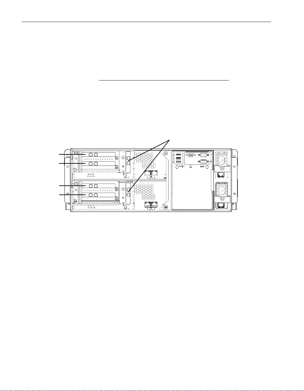
PCI Slot Numbering, Reservations, and Performance
Each CPU-I⁄ O enclosure in Express5800/320Ma 3.6 GHz and Dual-Core systems
contains one low-profile PCI slot that is physically labeled 1 and tw o additional
full-height PCI slots that are physically labeled 2 and 3 (see Figure 1-1). ftSMC displays
these slots as PCI Slot Info - 9, 10, and 11.
Similarly, each CPU-I⁄ O enclosure in Express5800/320Ma 3.2 GHz
one low-profile PCI slot that is physically labeled 1. ftSMC displays this slot as PCI Slot
Info - 9. In Express5800/320Ma 3.2 GHz systems, you can optionally install an AK533
attachment kit to add two full-height slots, providing the same configuration as
Express5800/320Ma 3.6 GHz and Dual-Core systems.
Each slot in a
100 megahertz (MHz). Slots 2 and 3, if present, ar e on on e de dicated PCIX 10 0- MHz
bus, with no other traffic. Slot 1 is on a 100-MHz bus, but shares this bus with the
embedded Ethernet adapters and with a PCI bridge that carr ies the VGA, USB, SATA
disk, CD-ROM, and VTM traffic.
Overview of PCI Adapters 1-3
Express5800/320Ma 3.2 GHz or 3.6 GHz system runs at a maximum of
systems contains
Page 14
Paired PCI Slots and Duplex Operation of PCI Adapters
No slots are reserved; however, you can install full-height PCI adapters only in slot 2
or slot 3.
See the Hardware Requirements section in each chapter for specific installation
recommendations for each adapter.
NOTE
You must insert PCI-slot filler panels in empty PCI slots to
maintain proper airflow.
Figure 1-1. PCI Adapter Slot Numbering
3
2
3
2
1
asys030
1Slot 1 - PCI Slot Info - 9 (low-profile slot)
2Slot 2 - PCI Slot Info - 10 (full-height slot, when present)
3Slot 3 - PCI Slot Info - 11 (full-height slot, when present)
Paired PCI Slots and Duplex Operation of PCI Adapters
Matched PCI adapters located in the same-numbered slot of two I/O elements are
known as paired adapters. For example, if you install the same model of PCI adapter
in PCI slots 10/1 and 11/1 (where 10 and 11 are the I /O element number s and 1 is t he
slot number), the adapters are paired.
As long as each PCI adapter in a pair is configured properly and functioning normally,
the pair of adapters is marked as duplexed in ftSMC, meaning th at th e ad a pte r s are
fault tolerant and safe to pull. If you remove one PCI adapter in the pair, the other
adapter keeps the system operational. Conversely, if one of the adapters in the pair is
missing, or if one of the adapters fails, the remaining adapter is marked as simplexed
in ftSMC, meaning that the adapter is not fault tolerant, and it is unsafe to pull.
1-4 Express5800/320Ma: PCI Adapter Guide
Page 15

General References
NOTE
If you remove a simplexed PCI adapter, or if it fails,
communications for applica tions related to that adapter
will terminate. Removing one of two duplexed PCI
adapters, however, will not affect communications. To
increase the fault tolerance of a system, alwa ys install PCI
adapters for critical applications in paired slots, and
ensure that the adapters are marked as duplexed in
ftSMC.
Duplex and simplex mode are also indicated on the PCI slot status LEDs that are
located at the rear of each system. Furthermore, because PCI slot status can affect
other subsystems, a missing or broken PCI adapter might change ftSMC properties
and LED states for an I/O enclosure as well as an entire system.
For more information about using ftSMC to dete rmine whether your PCI adapters or I/O
enclosures are operating in duplex mode, see the Express5800/320Ma: System
Administrator’s Guide. For information about using status LEDs to determine the PCI
slot status, see the operation and maintenance guide for your system, as listed in
Table 1-2.
General References
Table 1-2 lists the location of information about PCI adapters in other
Express5800/320Ma documents.
Table 1-2. General Reference Information for PCI Adapters
Topic Reference Document(s)
Hardware installation instructions Express5800/320Ma: Installation Guide
Overall view of system administration and
using ftSMC Express5800/320Ma: System Administrator’s Guide
Device IDs
Using VTM console to check system
software and network connections to the
VTM adapter, and to verify if the firmware
for the adapter is up to date.
Overview of PCI Adapters 1-5
Express5800/320Ma Virtual Technician Module User’s
Guide
Page 16

General References
Table 1-2. General Reference Information for PCI Adapters (Continued)
Topic Reference Document(s)
Status LEDs for I/O enclosures and PCI
slots
General troubleshooting procedures
General maintenance information
CRU replacement procedures
Express5800/320Ma: Operation and Maintenance
Guide
1-6 Express5800/320Ma: PCI Adapter Guide
Page 17

Chapter 2
Ethernet PCI Adapters
The following sections describe the supported Ethernet PCI adapters:
• “U575 Dual-Port Copper Gigabit Ethernet Adapters” on page 2-1
• “Embedded Ethernet PCI Adapters” on page 2-2
NOTE
Your system may also contain dedicated Ethernet ports
for U463 Virtual Technician Modules, but these Ethernet
ports are intended for a local maintenance network. For
more information, see the Express5800 /320Ma Virtual
Technician Module User’s Guide.
The following sections provide detailed information about Ethernet PCI adapters:
• “Hardware Requirements of Ethernet PCI Adapters” on page 2-3
• “Software Requirements of Ethernet PCI Adapters” on page 2-4
• “Cabling Requirements of Ethernet PCI Adapters” on page 2-5
2-
• “Configuring Ethernet PCI Adapters” on page 2-6
• “Troubleshooting Ethernet PCI Adapters” on page 2-35
U575 Dual-Port Copper Gigabit Ethernet Adapters
The U575 Dual-Port Copper Gigabit Ethernet Adapter is a low dual-port PCI ad apter
based on the Intel 82546 gigabit controller. The U575 PCI adapter supports
1000Base-T, 100Base-TX, and 10Base-T Ethernet network topologies with a PCI
data-path width of 64 bits.
If you order a U575 PCI adapter separately from the system, the adapter is outfitted
with a low-profile faceplate. A high-profile fa ceplate is a part of the kit. See Appendix A,
“Converting Adapters for Low- and High-Profile PCI Slots” for information about
converting the adapter for use in a high-profile slot.
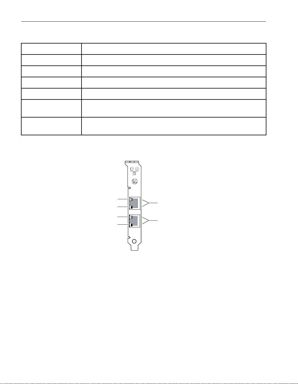
For a summary of its general features and requirements, see Table 2-6. For an
illustration of its faceplate, see Figure 2-1.
Ethernet PCI Adapters 2-1
Page 18
Embedded Ethernet PCI Adapters
Table 2-6. U575 PCI Adapter Features and Requirements Summary
Feature/Requirement Description
PCI Adapter Type Dual-port copper, 10/100/1000-Mbps Ethernet PCI adapter
Part No. AA-U57500
Supported systems Express5800/320Ma
3.2 GHz, 3.6 GHz, and Dual-Core
Required/Optional Optional
Slot Assignment Any slot; slot 2 or 3 in Express5800/320Ma 3.2 GHz, 3.6 GHz, and
Dual-Core systems for best performance
Cable Requirements Two UTP Ethernet cables with RJ-45 connectors, minimum Category 5
(customer-supplied)
Figure 2-1. Faceplate of the U575 PCI Adapter
ACT/LNK A
1
2
1
2
ACT/LNK B
3
4
spci004a
1 Activity/Link LED
2 10/100/1000-Mbps LED
3 Port A (port 0 in ftSMC)
4 Port B (port 1 in ftSMC)
Embedded Ethernet PCI Adapters
Your system contains two embedded 10/100/1000-Mbps Ethernet PCI adapters in
each CPU-I⁄ O enclosure. For diagrams of the ports for these adapters, see
Figure 2-23.
2-2 Express5800/320Ma: PCI Adapter Guide
Page 19

Hardware Requirements of Ethernet PCI Adapters
Requirements and configuration procedure s for t he embedded Ethernet PCI adapte rs
are similar to the procedures for the other Ethernet PCI adapters.
Hardware Requirements of Ethernet PCI Adapters
For fault tolerance, install Ethernet PCI adapte rs that are in the same team in different
I/O elements. Although teamed Ethernet PCI adapters in the same I/O element are
marked as duplexed in ftSMC, they are not fault to lerant. If the I/O element fails, or if
you remove the physical enclosure that contains the adapters (in a system with more
than one enclosure), network connectivity is lost.
Table 2-7 describes the slot-location requirements and recommendations for the
U574 PCI adapter and the U575 PCI adapter. If you plan to configure Ethernet PCI
adapters into teams, also consider the configuration requirements described in
“Configuring Ethernet Teams” on page 2-14.
Table 2-7. U575 PCI Adapter Slot Locations
System Slot-Location Requirements and Recommendations
Express5800/32
3.2 GHz,
0Ma
3.6 GHz, and
Dual-Core
For maximum throughput, install U574 PCI adapters and U575 PCI
adapters in a two-way symmetric multiprocessing (SMP) system. The
data load between teamed gigabit Ethernet PCI adapters is balanced
only in systems with two CPUs in each CPU enclosure.
For best performance, install multi-port Ethernet PCI adapters in slot 2 or
slot 3. (To add slots 2 and 3 in an Express5800/320Ma
install the AK533 attachment kit. See the Express5800/320Ma:
Operation and Maintenance Guide for more information.)
3.2 GHz system,
Table 2-8 lists the maximum number of Ethernet PCI ports that Express5800/320Ma
systems support.
Table 2-8. Maximum Number of Ethernet PCI Adapters
System
Express5800/
320Ma 3.2
‡
GHz
Express5800/
320Ma 3.6
U575 PCI
Adapter Maximum Number of Ports
28 (4
6 16 (6† ports, 2 on each unembedded adapter
†
ports, 2 on each unembedded adapter
and 4 on embedded Ethernet adapters)
and 4 on embedded Ethernet adapters)
†
GHz and
Dual-Core
Ethernet PCI Adapters 2-3
Page 20

Software Requirements of Ethernet PCI Adapters
† Each dual-port Ethernet PCI adapter appears as two adapters in PROSet,
Device Manager, and My Network Places.
‡ If you install the AK533 attachment kit in an Express5800/320Ma
system
in an Express5800/320Ma 3.6 GHz system.
, the maximum number of Ethernet PCI adapters will be the same as
3.2 GHz
Software Requirements of Ethernet PCI Adapters
Ethernet PCI adapters require the following software:
• sragbe.sys Ethernet driver
The Express5800/320Ma System Software initial program load (IPL) installs this
driver for all 10/100/1000-Mbps Ethernet adapters supplied by NEC Solutions
(America), Inc. PnP (Plug and Play) Manager recognizes the driver and loads it
automatically.
This Ethernet driver has an addedsurprise removal feature to increase fault
tolerance. The surprise removal feature prev ents system crashes in the event that
a PCI adapter is removed without software notification to the system.
NOTES
1. Using any other driver will invalidate the
Express5800/320Ma 100% A vailability Terms and
Conditions. For information about the
Express5800/320Ma 100% A vailability Terms and
Conditions, contact your representative.
2. To upgrade a driver, contact NEC Technical Support
or your authorized Service Representative.
• Intel(R) PROSet for Wired Connections utility, Version 9.0
The Express5800/320Ma System Software IPL installs this utility automatically.
Use PROSet to configure and troubleshoot Ethernet PCI adapters.
NOTE
Do not attempt to upgrade PROSet to a newer version of
this software available directly from Intel. If you install a
version of PROSet that is not qualified and released by
NEC Solutions (America), Inc., its installation procedure
will change the Express5800/320Ma default properties for
Ethernet PCI adapters.
2-4 Express5800/320Ma: PCI Adapter Guide
Page 21

Cabling Requirements of Ethernet PCI Adapters
Cabling Requirements of Ethernet PCI Adapters
The following sections describe the cabling requirements of the following Ethernet PCI
adapters:
• “Cabling U575 and Embedded Ethernet PCI Adapters” on page 2-5
NOTE
Label each cable that y ou attach to a PCI adapter, noting
the host name, I/O element number, PCI slot number, and
port number (if applicable) to which the cable connector
attaches.
Cabling U575 and Embedded Ethernet PCI Adapters
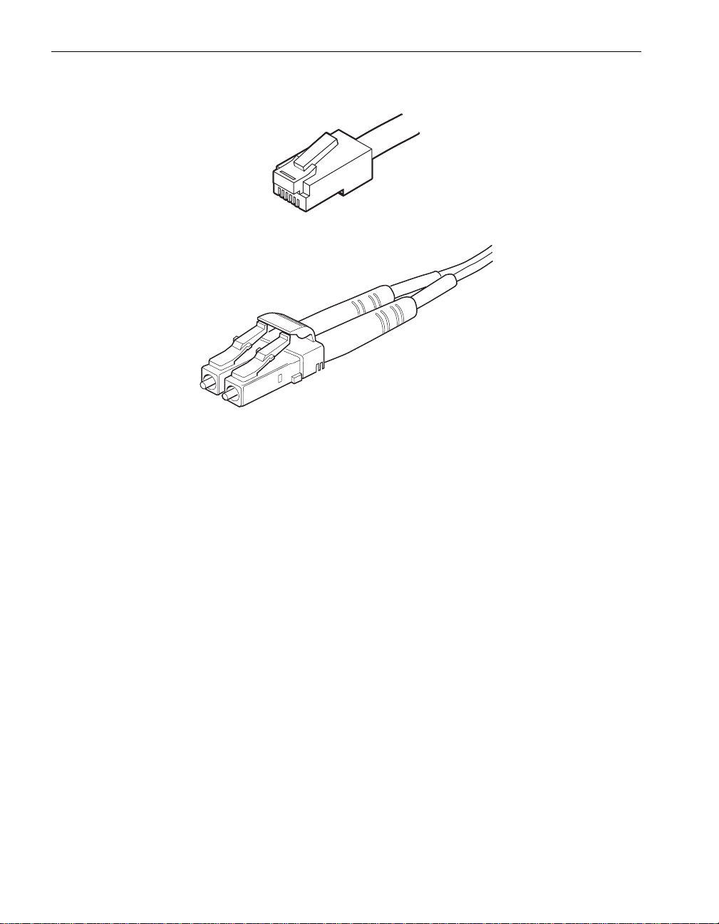
The U575 PCI adapter and embedded Ethernet PCI adapters require
customer-supplied, Unshielded Twisted Pair (UTP) Ethernet cables with RJ-45
connectors (see Figure 2-2). For each port, supply a 24 AWG, 4-pair, UTP
EIA/TIA-Verified, Category-3 or Category-5 wire cable, with RJ-45 modular connectors
terminated with pair-wiring adhering to the EIA/TIA 568-A or EIA/TIA 568-B standard.
The speed of the network determines the grade of UTP cable that you can use:
• 10 Mbps requires UTP Category-3 or Category-5 Data-Grade cable.
• 100 Mbps and 1000 Mbps require UTP Category-5 Data-Grade cable. Use of
Category-3 Data-Grade cable f or 100 Mbps or 1000 Mbps wo uld cause data loss .
For 1000 Mbps, use Category-5e Data-Grade cable.
To connect to an Ethernet hub or switch, use a straight-through cable, not a
crossed-pair (1-3, 2-6) cable or an Ethernet crossover cable. The maximum distance
between the PCI adapter and an Ethernet hub or a switch is 328 ft (100m).
Ethernet PCI Adapters 2-5
Page 22
Configuring Ethernet PCI Adapters
Figure 2-2. RJ-45 Connector
mpci009
mpci083
Configuring Ethernet PCI Adapters
Use the PROSet utility to configure Ethernet PCI adapters (see “Starting PROSet” on
page 2-7). PROSet is part of the Ethernet PCI adapter software.
Use PROSet to perform the following tasks:
• Locate a PCI adapter (see “Locating Ethernet PCI Adapters” on page 2-15) in a
system with many Ethernet PCI adapters.
• Configure the line speed and/or duplex mode of an Ethernet PCI adapter with
values appropriate to the adapter and the media to which it connects (see
“Configuring Link Speed and Duplex Mode” on page 2-16).
• Configure Ethernet PCI adapters into teams (see “T ypes of F ault-Tolerant Et hernet
Teams” on page 2-9). For information about how to configure the teams, see
“Configuring Ethernet Teams” on page 2-14.
• Assign virtual LANs to a team (see “Virtual LANs” on page 2-13). For information
about how to configure the VLANs , see “Configuring Virtual LANs Over a Team” on
page 2-22.
• Manage a team by removing or adding adapters, or removing the team (see
“Managing Ethernet Teams” on page 2-27).
• Modify the advanced settings of an indi vidual Ethernet PCI adapter, a team, or a
VLAN (see the PROSet online help).
2-6 Express5800/320Ma: PCI Adapter Guide
Page 23

Configuring Ethernet PCI Adapters
• Troubleshoot Ethernet PCI adapters (see “Using PROSet Utility Diagnostics” on
page 2-41).
NOTES
1. In systems with more than one enclosure, you can
physically remov e an enclosure without disrupting the
network only if the active Etherne t PCI adapters i n
the enclosure are teamed with adapters in another
enclosure. Note that with Adaptive Load Balancing
and Link Aggregation teams, your system will
experience a drop in throughput whil e the enclosure
is absent.
2. For fault tolerance, configure your Ethernet PCI
adapters into teams. Although Express5800/ 320Ma
systems support unteamed Ethernet PCI adapters,
an unteamed Ethernet PCI adapter is a single point of
failure that can cause the loss of a network
connection.
3. After you finish each configuration procedure using
PROSet, click Apply or OK in the Intel(R) PROSet
for Wired Connections dialog box (see Figure 2-3
for an example of the dialog box) to preserve your
changes. If you do not click Apply or OK before
exiting PROSet, it cannot finish processing the
configuration procedure, and you must repeat the
procedure.
Starting PROSet
To start the PROSet utility, use one of the following methods:
NOTE
Before starting PROSet, close the Local Area
Connection n Properties dialog boxes (Figure 2-13) for
all Ethernet PCI adapters; any open Properties dialog
box can cause problems for viewing and setting values in
PROSet.
• Double-click PROSet in the system tray:
• Double-click PROSet in the Control Panel:
Ethernet PCI Adapters 2-7
Page 24

Configuring Ethernet PCI Adapters
A PROSet dialog box appears (see Figure 2-3 for an example).
Figure 2-3. Initial PROSet Dialog Box
If you need to start PROSet remotely, you can use Windows Remote Desktop to
access PROSet (and the system’s desktop). You can then create or modify a team if it
is not carrying your connection to the system.
2-8 Express5800/320Ma: PCI Adapter Guide
Page 25

NOTES
1. When you are using PROSet remotely through
Remote Desktop, do not modify the team that
provides your connection to the system. Doing so will
result in a loss of network connection.
2. Only one user can access PROSet at a time. If you
attempt to start PROSet and nothing happens,
another user might be running PROSet in a Remote
Desktop session. Use Task Manager to check for the
PROSet.exe process.
For more information about the PROSet utility, read the PROSet online help, which you
access by clicking Help from the PROSet main window.
Types of Fault-Tolerant Ethernet Teams
You can configure Ethernet PCI adapters into teams to increase fault tolerance or
performance, or both.
In a team, one Ethernet PCI adapter is the primary adapter (or activ e adapter) , and all
other Ethernet PCI adapters are secondary adapters (or backup adapters). In some
cases, the primary adapter is the only active adapter of the team; the secondary
adapter becomes active only if the primary adapter f ails. In other cases, all members
of the team actively pass traffic to increase overall transmit or receive throughput.
Configuring Ethernet PCI Adapters
When you create a team, PROSet automatically assigns the primary and secondary
adapters; however, if necessary, you may manually designate one primary and one
secondary adapter per team. For example, if you are creating a team with mixed
Ethernet PCI adapters, you might want t o designate the fastest a dapter as the primary
adapter.
Typically, the permanent Media Access Control (MAC ) address of the primary Ethernet
PCI adapter becomes the current MAC address for all Ethernet PCI adapters in one
team. (The MAC address is the PROSet Ethernet Address.)
Express5800/320Ma systems support the following types of Ethernet fault-tolerant
teams:
• “Adapter Fault Tolerant Teams”
• “Switch Fault Tolerant Teams”
• “Adaptive Load Balancing Teams”
• “Static Link Aggregation Teams”
• “IEEE 802.3ad Dynamic Link Aggregation Teams”
Ethernet PCI Adapters 2-9
Page 26

Configuring Ethernet PCI Adapters
You can assign any Ethernet PCI adapter supplied by NEC Solutions (America), Inc.
to any type of team, with some exceptions for static link aggregation teams. See “Static
Link Aggregation Teams” on page 2-11 for details.
NOTE
Also see the PROSet online help for additional teaming
information and restrictions.
Adapter Fault Tolerant Teams
An Adapter Fault Tolerant (AFT) team is a set of two or more Ethernet PCI adapters
that provide redundant connections to a single switch. In an AFT team, the primary
adapter executes all transmit and receive functions for the team. The secondary
adapter becomes active after a failover to the secondary adapter occurs, generally
when the primary adapter fails.
Switch Fault Tolerant Teams
A Switch Fault Tolerant (SFT) team is similar to an AFT team, except that SFT allows
you to connect the team members to separate switches for increased fault resiliency.
An SFT team must contain exactly two Ethe rnet PCI adapters, and you must connect
each adapter to a different switch that supports the Spanning Tree Algorithm. As in an
AFT team, the primary adapter executes all transmit and receive functions for the team.
The secondary adapter becomes active after a failover to the secondary adapter
occurs, generally when the primary adapter fails or its link to the switch fails.
Adaptive Load Balancing Teams
In an Adaptive Load Balancing (ALB) team, both the primary and secondary Ethernet
PCI adapters execute the transmit function, while only t he primary adapter executes
the receive function. (ALB functionality also includes AFT feat ures.)
To prevent packet-order problems, one adapter in an ALB team transmits all packets
that have the same destination. In addition, only the primary adapter transmits
broadcast packets and non-Internet Protocol (IP) packets.
You must connect all adapters in an ALB team to the same switch, or to two or more
hubs that connect to the same switch.
NOTE
When you create a ne w ALB team, PROSet au tomatically
sets the Receive Load Balancing property for the team
to On to balance received traffic over all members of the
team. However, enabling this feature for ALB teams can
cause connectivity problems. I f the primary adapter in the
team fails when this feature is enabled, the Ethernet
address of the team automatically changes to the M AC
2-10 Express5800/320Ma: PCI Adapter Guide
Page 27

address of the new primary adapter. As a result, some
packets are dropped until the new primary adapter can
reestablish connections using the new Ethernet address
(possibly a 30-second or more delay). To disable receive
load balancing and to improve fault tolerance, you m ust
manually set the value of the Receive Load Balancing
property to Off in the Advanced tab for the ALB team.
(The ALB team continues to balance traffic th at th e te am
transmits.)
Static Link Aggregation Teams
Static link aggregation increases transmission and reception throughput by balancing
both transmit and receive traffic over all members of the t eam. (Static link aggre gation
also includes AFT features.)
You must connect all members of a static aggregation team to a single switch that
supports either the Fast EtherChannel (FEC) standard or the Gigabit EtherChannel
(GEC) standard, and the relevant switch ports must be properly configu red for it. When
you create a static link aggregation team, it automatically negotiates a FEC or GEC
connection, depending on the type and configuration of the switch.
Table 2-9 lists the types of static link aggregation teams that each Eth ernet PCI adapter
supports. See your switch documentation to determine which types of teams it
supports.
Configuring Ethernet PCI Adapters
Table 2-9. Supported Ethernet Fault-Tolerant Teams
Ethernet
PCI Adapter FEC GEC
Embedded
10/100/1000-Mbps
U575 Y es (when configured at
Yes (when configured at
10- or 100-Mbps)
10- or 100-Mbps)
Yes (when configured
at 1000-Mbps)
Yes (when configured
at 1000-Mbps)
IEEE 802.3ad Dynamic Link Aggregation Teams
IEEE 802.3ad Dynamic Link Aggregation teams provide full transmit and receive load
balancing like the FEC and GEC standards, but in a dynamic-mode implementation.
Dynamic mode is an implementation of the final 802.3ad specification.
Many switches support an implementation of only the dr aft 802.3ad specification, which
does not include dynamic mode. To determine whether you r switch is fully compatib le
with the dynamic-mode implementation of the 802.3ad standard, contact your switch
vendor.
Ethernet PCI Adapters 2-11
Page 28

Configuring Ethernet PCI Adapters
Note that the Ethernet PCI adap ters in an 802.3ad team cannot be connected to a hu b.
The adapters must be connected to a single switch that supp orts the final 802.3ad
specification, and the relevant switch ports must be properly co nfigured for it. (802.3ad
teams also include AFT features.)
NOTE
To maximize performance with dynamic link teams, use
fewer teams, but more Ethernet PCI adapters in each
team.
Fault-Tolerant Ethernet T eams and IP Multicasting
If IP multicasting is in use on your network, consider the following restriction when
choosing the type of fault-tolerant team to configure .
Each network host in an IP multicast group uses the Internet Group Management
Protocol (IGMP) to acknowledge and maintain its IP mu lticast group me mbership with
a switch.
In an AFT, SFT, or ALB team, only one Ethernet PCI adapt er (the primary adapter) is
registered to receive IP multicast packets. When failover to another adapter occurs, the
host cannot automatically update its multicast group membership using the new
primary adapter; therefore, the host stops receiving multicast packets. If the switch is
configured to periodically query the host for its registration, or if static IGMP is
configured on the switch for each adapter in the team, multicasting to the host will
eventually resume, but possibly after an extended interruption.
If you use IP multicasting, and you want to configure an AFT, SFT, or ALB team, you
should test the team on site to verify if the behavior of IP multicasting after failover is
acceptable. Alternatively, you can configure either static or dynamic link aggregation
teams. IP multicasting functions more reliably with qualified switches that support these
modes, because all Ethernet PCI adapters in a link a ggregation team are r egistered to
receive the IP multicast packets. The team continues to receive IP multicast packets
unless all links to the switch are lost and then restored (in which case, there is also a n
extended interruption).
For more information about IP multicasting, see the docu mentatio n for your switch, or
contact your network administrator.
2-12 Express5800/320Ma: PCI Adapter Guide
Page 29

Virtual LANs
You can add a Virtual LAN (VLAN) to any type of Ethernet team.
A VLAN allows you to isolate network traffic f or a specific group of network hosts. Using
VLANs, you can organize networked systems into logical workgroups, such as
Marketing or Engineering, that span a building, complex, or an entire enterprise
network. Members of a particular VLAN receive traffic only from other members of the
same VLAN.
VLANs are particularly useful for limiting broadcast sto rms, reducing security problems,
and simplifying network management.
There are two types of VLANs:
• Implicit VLANs, which are configured entirely at the switch level. The switch does
not alter or tag packets to enforce an implicit VLAN.
• Explicit VLANs, which are configured throughout the network, on each adapter and
link partner. Switches identify and route traffic based on a four-byte tag (802.3ac)
in each packet header.
To support either type of VLAN, switches on your network must support 802.1Q
VLANs. Also, to configure a VLAN on your system, you need to contact your network
administrator to obtain the VLAN ID for your workgroup, which must be identical to the
VLAN ID programmed into the switches.
Configuring Ethernet PCI Adapters
NOTE
NEC Solutions (America), Inc. supports VLANs only over
Ethernet teams, not over individual adapters. An
unteamed adapter is a single point of failure that can
cause the loss of a network connection.
In an environment with many VLAN workgroups, you can optionally implement the
GARP VLAN Registration Protocol (GVRP) to dynamically create, change, and remove
VLANs. To support GVRP, all adapters and switches on your network must have
GVRP enabled. For information about configuring and using GVRP, see the PROSet
online help and the documentation for your switch, or contact you r network
administrator.
Ethernet PCI Adapters 2-13
Page 30

Configuring Ethernet PCI Adapters
Configuring Ethernet Teams
Use the PROSet utility to configure Ethernet PCI adapters into teams. Keep the
following notes, guidelines, and restrictions in mind when you create a t eam:
• If you disable a team b ut subsequently make and apply any change s in the PROSet
utility , PROSet enables the team again. Clic king Apply in the PROSet utility enables
all teams. To disab le the teams again, use Device Manager or My Network Places .
• Each port on a dual-port Ethernet PCI adapter appears as a separate adapter in
PROSet.
• Generally, assign Ethernet PCI adapters of only one media type (fiber optic or
copper) to a team. For instance, you should assign only U574 PCI adapter ports
(fiber optic) to a team, or only U575 PCI adapter ports (copper). You could also
assign embedded 10/100/1000-Mbps Ethernet PCI adapter ports (copper) and
U575 PCI adapter ports (copper) to a team.
• Manually configure values for the data rate and duplex mode of Ethernet PCI
adapters that operate at 1 0 or 100 Mbps (see “C onfiguring Link Speed and Duple x
Mode” on page 2-16). Although these values are set automatically by default,
automatic settings can result in unreliable connect ions and inaccurate reporting of
link activity and duplex mode. Always use the same data rate and duplex mode
values for all members of a team.
• PROSet supports 2-8 Ethernet PCI adapters (ports) in a team. For teaming
purposes, some switches might require y ou to p opulate sets o f two - or four-switch
ports at a time. Determine the requirements of the switch that you are using, and
add the appropriate number of adapters to the team.
• There is no minimum or maximum number of t eams in PR OSet; te ams are limited
only by the number of adapters available in your system and how you allocate
them.
• For fault tolerance , create teams that contain Ethernet PCI adapters from different
I/O elements. Only teams with Ethernet PCI adapters in differ ent I/O elements are
fault toler ant. (S ee “Locating Ethernet PCI Adapters” on page 2-15 for information
about using PROSet to locate Ethernet PCI adapters.)
• NEC Solutions (America), Inc. does not support the creation of Express Teams.
PROSet Express Teams provide a quick way of teaming all ports of a multiport
Ethernet PCI adapter. Because t he ports are in the same adapter and I/O element,
an Express Team is a single point of failure.
• NEC Solutions (America), Inc.does not support the teaming of third-party Ethernet
PCI adapters with Express5800/320Ma Ethernet PCI adapters. Only
Express5800/320Ma Ethernet PCI adapters have been tested for compatibility and
fault tolerance in Express5800/320Ma systems.
To configure Ethernet PCI adapters into fault-tolerant teams, perform the procedures
described in the following sections, in the order listed.
2-14 Express5800/320Ma: PCI Adapter Guide
Page 31

1. “Locating Ethernet PCI Adapters” on page 2-15
2. “Configuring Link Speed and Duplex Mode” on page 2-16
3. “Creating Ethernet Teams” on page 2-18
4. “Configuring Virtual LANs Over a Team” on page2-22
5. “Verifying the Configuration of Teams and VLANs” on page 2-23
6. “Assigning an IP Address to a Team or VLAN” on page 2-24
Locating Ethernet PCI Adapters
When you create a team of Ethernet PCI ada pters, you need to include adapte rs from
different I/O elements for increased fault tolera nce .
To verify that you are selecting the appropriate adapter s, you can use the Identify
Adapter feature of PROSet, which flashes a status LED in a specific Ethernet port on
demand so you can visually identify it. This feature is compatible with all
Express5800/320Ma Ethernet PCI adapters, including embedded Ethernet PCI
adapters.
NOTE
To determine which LED on the Ethernet port will flash,
see “Checking Status LEDs” on page 2-36.
Configuring Ethernet PCI Adapters
To locate an Ethernet PCI adapter port
1. Start the PROSet utility if you have not already done so (see “Starting PROSet” on
page 2-7).
2. In the Intel(R) PROSet for Wired Connections dialog bo x, right-click a teamed o r
unteamed Ethernet PCI adapter (port), and click the General tab (Figure 2-3).
3. In the General tab, click Identify Adapter.
4. In the Identify Adapter dialog box (Figure 2-4), specify the amount of time (in
seconds) you want the LED on the Ethernet PCI adapter port to flash. (Consider
the time it will take you to reach the rear of the system to see the LED flash.)
Ethernet PCI Adapters 2-15
Page 32

Configuring Ethernet PCI Adapters
Figure 2-4. Identify Adapter Dialog Box
5. Click Start to flash the LED.
The LED flashes for the specified n umb er of seconds. Find the Ethernet port with
the flashing LED and make note of its device name in PROSet.
6. When the flashing stops, y ou can click Start to flash the LED again or Close to
dismiss the Identify Adapter dialog box. If necessary, repeat steps 2-6 to locate
additional adapters.
Configuring Link Speed and Duplex Mode
By default, Ethernet ports onU575 Ethernet PCI adapters and embedded Ethernet PCI
adapters are configured to autonegotiate the best speed for a connection. On a
network that operates at 10 or 100 megabits per second (Mbps), automatic settings can
result in unreliable connections and inaccurate reporting of link act ivity and duplex
mode. For reliable operation, manually configure the link speed and duplex mode for
all Ethernet PCI adapters connected to networks that operate at 10 or 100 Mbps.
NOTES
1. For Ethernet adapters or ports connected to networks
running at 1 gigabit per second (Gbps), rely on
autonegotiation. Do not manually configure 1-Gbps
operation.
2. Express5800/320Ma systems support 1-Gbps line
speed only in full-duplex mode.
When you manually set these values, make sure that the values are identical for the
Ethernet port and the link partner to which it connects, and that the settings for all
Ethernet ports in one team are the same.
2-16 Express5800/320Ma: PCI Adapter Guide
Page 33

Configuring Ethernet PCI Adapters
To set the link speed and duplex mode
1. Start the PROSet utility if you have not already done so (see “Starting PROSet” on
page 2-7).
2. In the left pane of the Intel(R) PROSet for Wired Connections dialog box, click
an adapter. (Each port on a dual-port Ethernet PCI adapter appears as a separate
PCI adapter in PROSet.) If necessary, expand a team to access its member
adapters.
3. Click the Speed tab.
4. Under Link Speed and Duplex Settings, select the speed and duplex mode
appropriate to the port and to the type of line to which the port is connected.
Figure 2-5 shows how to specify 100 Mbps and full duplex for one of the ports on
a U575 Dual-Port Copper Gigabit Ethernet Adapter.
Figure 2-5. Setting the Link Speed and Duplex Mode
5. Repeat steps 2 through 4 for each Et hernet PCI adapter f or which y ou need to set
the link speed and duplex mode.
6. Click Apply to process and preserve the changes. Allow several seconds for
PROSet processing time.
7. In the General tab for each adapter you updated, verify that the link speed and
duplex settings are correct and, if a network cable is attached, that a link is
established (Figure 2-6).
Ethernet PCI Adapters 2-17
Page 34

Configuring Ethernet PCI Adapters
Figure 2-6. Verifying Link Speed, Duplex Mode, and Link Activity
If necessary, also verify the actual link speed and duplex mode LEDs on the
Ethernet PCI adapters and the remote ports to which they are connected. If the link
speed and duplex mode are incorrect, try removing and replacing the netwo rk
cables. If the link speed and duple x mode are still incorrect, verify that your network
equipment supports the link speed and duplex mode that you set.
8. Click OK to exit PROSet.
Creating Ethernet Teams
CAUTION
!
Creating an Ethernet team disrupts the network traffic
over all Ethernet PCI adapters in the team.
1. Start the PROSet utility if you have not already done so (see “Starting PROSet” on
page 2-7).
2. In the Intel(R) PROSet for Wired Connections dialog box, right-click one of the
Ethernet PCI adapters listed, point to Add to Team, and then click Create New
Team.
The Teaming Wizard starts.
3. In the first dialog box of the Teaming Wizard (Figure 2-7), select the type of team
you want to create (for example, Adapter Fault Tolerance), and then click Next.
Depending on the teaming mode you select, PROSet might displa y an other dialog
box with information about the restrictions for that mode. Click Next to continue.
2-18 Express5800/320Ma: PCI Adapter Guide
Page 35

Figure 2-7. Selecting the Type of Team
Configuring Ethernet PCI Adapters
4. In the next dialog bo x of the T eaming Wizar d, select the Ethernet PCI adapters for
the team by clickin g the chec k bo x e s ne xt to each adapter. As you select adapters
for a team, follow the cautions and notes listed at the beginning of this section
(“Configuring Ethernet Teams” on page 2-14).
Figure 2-8 shows an example of selecting four U575 PCI adapters for a team.
Ethernet PCI Adapters 2-19
Page 36

Configuring Ethernet PCI Adapters
Figure 2-8. Selecting Ethernet PCI Adapters for a Team
5. After you have selected the Ethernet PCI adapters for the team, click Next, and
then click Finish.
6. When the Intel(R) PROSet for Wired Connections dialog box reappears, click
Apply. (Do not designate primary or secondary adapters at this time.) PROSet
begins to bind the specified PCI adapters into teams. This o peration takes at least
one minute per team to complete. Do not abort the operation until it has
completed; otherwise, you must repeat the procedure.
7. After creating the teams, if necessary, you can manually designate a primary and
secondary adapte r for each team.
a. In the left pane of the Intel(R) PROSet for Wired Connections dialog box,
expand the team and Member Adapters.
b. Right-click the Ethernet PCI adapter you want as the primary adapter, and
select Preferred Primary from the menu. Figure 2-9 shows an example of
specifying the primary adapter in a team of U575 PCI adapter s.
c. Right-click the Ethernet PCI adapter you want as the secondary adapter, and
select Preferred Secondary from the menu.
2-20 Express5800/320Ma: PCI Adapter Guide
Page 37

Figure 2-9. Assigning Priorities to Ethernet PCI Adapters
Configuring Ethernet PCI Adapters
NOTE
You can select only one primary adapter and only one
secondary adapter for a team. If you select another
primary or secondary adapter, it overrides your initial
selection. To confirm your selections, right-click the
adapters again. A check mark beside Preferred Primary
indicates that the Ethernet PCI adapter is the primary
adapter , and a chec k mark beside Preferr ed Secondary
indicates that the adapter is the secondary adapter.
8. Click Apply to process the changes. Allow time for PROSet to complete the
procedure.
Ethernet PCI Adapters 2-21
Page 38

Configuring Ethernet PCI Adapters
Configuring Virtual LANs Over a Team
CAUTION
!
Configuring a VLAN over an Ethernet team disrupts the
network traffic over the team.
NOTE
Configuring VLANs is optional. You can ha ve an Ethernet
team without VLANs.
1. Start the PROSet utility if you have not already done so (see “Starting PROSet” on
page 2-7).
2. In the left pane of the Intel(R) PROSet for Wired Connections dialog box,
right-click the appropriate team. In the menu that appears, click Add VLAN (see
Figure 2-11).
Figure 2-10. Adding a VLAN t o a Team
3. In the Add New VLAN dialog box (Figure 2-11), enter the VLAN ID. The VLAN ID
must match the VLAN ID configured on the switch.
2-22 Express5800/320Ma: PCI Adapter Guide
Page 39

Configuring Ethernet PCI Adapters
Figure 2-11. Specifying a VLAN ID and Name
4. In the same dialog box, enter a Name for the VLAN. The name is only for
identification, and it does not need to match th e name of VLAN on other network
devices.
5. Click OK. The new entry for the VLAN appears in Virtual LANs, under the team
entry in the left pane of the Intel(R) PROSet for Wired Connections dialog box.
To add additional VLANs, repeat step 2-5. (You can create up to 64 VLANs on a
system.)
6. Click Apply in the Intel(R) PROSet for Wired Connections dialog box to process
and save the ch anges.
Verifying the Configuration of Teams and VLANs
1. Close and restart the PROSet utility (see “Starting PROSet” on page 2-7). In
PROSet, ensure that:
• The teams and VLANs have been created as you expected.
• All Ethernet PCI adapters in a team use the same Ethernet address, and th at
address is the permanent Ethernet address of one of the Ethernet PCI
adapters in the team. (For ALB teams with receive load balancing enabled,
each Ethernet PCI adapter uses its own permanent Ethernet address.) See
“Updating a Team’s Ethernet Address” on page 2-32 for more information.
Ethernet PCI Adapters 2-23
Page 40

Configuring Ethernet PCI Adapters
2. Verify that an IP address has been assigned to each team or VLAN.
• If you have created a team without VLANs, the team requires an IP address.
(The individual Ethernet PCI adapters in a team have no IP addresses.)
To find the IP address for a team in PROSet, click the entry for the team and
see the IP Address in the Team Configuration tab.
• If you hav e created a team with VLANs, ea ch VLAN in that team requires an IP
address. (The team and the Ethernet PCI adapters in the team have no IP
addresses.)
To find the IP address for a VLAN in PR OSet, clic k the en try for the VLAN and
see the IP Address in the VLAN Configuration tab.
If a team or VLAN does not have an IP address, assign it one. See “Assigning an
IP Address to a Team or VLAN” on page 2-24.
3. Start ftSMC, select each Network P ort you teamed, and in the details pane, verify
that the value next to OpState: State is Duplexed.
Assigning an IP Address to a Team or VLAN
1. Click Start, point to Control Panel, and double-click Network Connections.
2. In the Network Connections control panel (see Figure 2-12 for an example),
right-click the appropriate Team #n or VLAN Name, ID: n icon , and th en c lick
Properties.
2-24 Express5800/320Ma: PCI Adapter Guide
Page 41

Figure 2-12. Network Connections Window
Configuring Ethernet PCI Adapters
3. In the Team #n Properties or VLAN Name, ID: n Properties dialog box (see
Figure 2-13), click Internet Protocol (TCP/IP), and click Properties.
Ethernet PCI Adapters 2-25
Page 42

Configuring Ethernet PCI Adapters
Figure 2-13. Ethernet Team Properties
4. In the Internet Protocol (TCP/IP) Properties dialog bo x (see Figure 2-14), select
Obtain an IP address automatically or Use the following IP address. If you
select Use the following IP address, enter the IP address, subnet mask, and
default gateway. Consult your network administrator for all TCP/IP property
settings.
NOTE
Your TCP/IP property settings must match the
configuration of the network to which the team or VLAN is
connected. Select Obtain an IP address automatically
only if the network supports it. If you select it and the
network does not support it, the Ethernet PCI adapter may
be unusable.
2-26 Express5800/320Ma: PCI Adapter Guide
Page 43

Figure 2-14. Internet Protocol (TCP/IP) Properties
Configuring Ethernet PCI Adapters
5. Click OK to accept the changes.
6. In the Team #n Properties or VLAN Name, ID: n Properties dialog box, click
Close to process the new TCP/IP settings and to close the dialog box.
7. Restart PROSet and verify that the new IP address appears in the Team
Configuration tab for the team or VLAN Configuration tab for the VLAN.
Managing Ethernet Teams
The following sections explain how to manage teams with the PROSet utility:
• “Removing Ethernet PCI Adapters from a Team” on page 2-28
• “Adding Ethernet PCI Adapters to a Team” on page 2-31
Ethernet PCI Adapters 2-27
Page 44

Configuring Ethernet PCI Adapters
• “Updating a Team’s Ethernet Address” on page 2-32
• “Removing an Ethernet Team” on page 2-34
NOTES
1. Anytime you modify an existing team, you might
temporarily interrupt the flow of network traffic to the
team.
2. When you add or remov e Ethernet PCI adapters in an
existing Static Link Aggregation team, the link to the
adapters you are adding or removing must be down;
otherwise, the switch forwards traffic to the adapters
before the configuration is complete.
3. When you remove or replace a teamed adapter, you
might need to reset the Ethernet (MAC) address of
the team as described in “Updating a T eam’s Ethe rnet
Address” on page 2-32. In addition, your network
administrator must update any network filtering or
security settings that might be based on the MAC
address of the Ethernet adapter you removed.
Removing Ethernet PCI Adapters from a Team
NOTE
Remove Ethernet PCI adapters from only one team at a
time. Complete the proc edure before removing an ad apter
from another team.
1. Start the PROSet utility if you have not already done so (see “Starting PROSet” on
page 2-7).
2. In the left pane of the Intel(R) PROSet for Wired Connections dialog box, expand
the team and Member Adapters.
3. To remove an Ethernet PCI adapter from the team, right-click t he adapter and click
Remove from Team (Figure 2-15).
NOTE
If you select Remove Adapter by mistake when you
meant Remove from Team, click Cancel to cancel the
changes and to close PROSet, then restart PROSet and
start the procedure again. If you apply the changes, use
Scan for Hardware Changes in Device Manager to
reinstate the adapter.
2-28 Express5800/320Ma: PCI Adapter Guide
Page 45

Configuring Ethernet PCI Adapters
Figure 2-15. Removi ng an Ethe rnet PCI Adapter from a Team
4. A confirmation message appears. If there are only two Ethernet PCI adapters in
the team, PROSet warns yo u about leaving the team with only one adapter
(Figure 2-16). Click OK.
Repeat steps 3-4 for each adapter you intend to remove from the team.
Figure 2-16. Confirmation Message: Removing an Ethernet PCI Adapter from a Team
5. When the Intel(R) PROSet for Wired Connections dialog box reappears, if
necessary, you can manually designate new primary and secondary adapters for
the team. See step 7 of “Creating Ethernet Teams” on page 2-18.
(If you are removing the primary or secondar y adapter in the team, PROSet will
automatically designate other team members to fill these roles, but you can
optionally assign them yourself.)
Ethernet PCI Adapters 2-29
Page 46

Configuring Ethernet PCI Adapters
6. Click Apply to process and save the changes.
7. If you are not physically replacing the Ethernet PCI adapters that you removed,
update the Ethernet address of the team at this time. See “Updating a Team’s
Ethernet Address” on page 2-32.
If you intend to physically replace the adapters you removed, complete the
following procedure.
To physically replace adapters in a team
1. In systems with hot-pluggable enclosures, if you intend to maintain network
connectivity while removing an enclosure, verify that all active Ethernet PCI
adapters in the enclosure are teamed with adapters in another enclosure. See
“Locating Ethernet PCI Adapters” on page 2-15 to determine the location of
Ethernet PCI adapters in the system.
2. Click OK to exit PROSet.
3. Physically remove the Ethernet PCI adapters from the system and install the new
adapters. For more information about removing and replacing adapters, see the
operation and maintenance guide for your system, as listed in Table 1-2.
NOTE
If you intend to use the old Ethernet PCI adapters in othe r
systems, do not install them in other systems until you
reset the Ethernet address of the team (when you reach
step 5 of “Adding Ethernet PCI Adapters to a Team”).
4. Start the PROSet utility (see “Starting PROSet” on page 2-7).
5. Remove the entries f or the Ethernet PCI adapters that you ph ysically removed from
the system. The entries should have an icon with an X to indicate that these
adapters are missing (Figure 2-17).
For each adapter you want to remove, right-click the adapter entry and select
Remove Adapter. When you are finished, click Apply to process the changes.
Figure 2-17. Icon for a Missing (Removed) Adapter
6. Add the new Ethernet PCI adapters to the team, as “Adding Ethernet PCI Adapters
to a Team” describes.
2-30 Express5800/320Ma: PCI Adapter Guide
Page 47

Adding Ethernet PCI Adapters to a Team
NOTE
Add Ethernet PCI adapters to only one team at a time.
Complete the procedure before adding an adapter to
another team.
1. Start the PROSet utility if you have not already done so (see “Starting PROSet” on
page 2-7).
2. In the left pane of the Intel(R) PROSet for Wired Connections dialog box,
right-click the appropriate team. In the menu that appears, click Add Adapter to
Team, then select the adapter you want to add to the team.
Repeat this step for any adapters you want to add to the team.
Figure 2-18 shows an example of adding a U574 PCI adapter to a team.
Figure 2-18. Adding an Adapter to a Team
Configuring Ethernet PCI Adapters
3. If necessary , you can man ually designate new primary and secondary adapters for
the team. See step 7 of “Creating Ethernet Teams” on page 2-18.
(If you have not previously select ed primary or secondary adapters for the team,
PROSet will automatically designate adapters to fill these roles.)
4. Click Apply to process and save the changes.
Ethernet PCI Adapters 2-31
Page 48

Configuring Ethernet PCI Adapters
5. If necessary, reset the Ethernet address of the team. See “Updating a Team’s
Ethernet Address” on page 2-32.
6. If you have not already done so, connect the new Ethernet PCI adapters to the
network.
7. Verify the configuration of the team. See “V erifying the Configur ation of Teams and
VLANs” on page 2-23.
Updating a Team’s Ethernet Address
When you replace a primary PCI adapter, you must assign the correct Ethernet
address to the team before you connect the new primary adapter to the ne twork.
Typically, the Ethernet address of a team is the p ermanent MAC address of the primary
adapter. When you replace a primary adapter, the team by default continues to use the
MAC address of the adapter you removed. Therefore, after you replace an adapte r, you
must assign the team an Ethernet address that matche s the permanent MAC address
of one of the Ethernet PCI adapters currently in the system.
CAUTION
!
The network connection is disrupted when you update a
team’s Ethernet address.
If necessary, verify that the team’s current Ethernet address is identical to the
permanent Ethernet address of one of the team members.
To verify the Ethernet address fo r a tea m
1. Start the PROSet utility if you have not already done so (see “Starting PROSet” on
page 2-7).
2. To obtain the current Ethernet address of a team, clic k the appropriate team in th e
left pane of the Intel(R) PROSet for Wired Connections d ialog box, t hen click the
Team Configuration tab. Note the value of Ethernet Address under Team
Information (Figure 2-19).
2-32 Express5800/320Ma: PCI Adapter Guide
Page 49

Configuring Ethernet PCI Adapters
Figure 2-19. Obtaining the Ethernet Address for a Team
3. To obtain the permanent Ethernet address of each Ethernet PCI adapter, click the
adapter in the device tree, click the General tab, and click Adapter Details. Note
the value of Permanent Ethernet Address (Figure 2-20).
Figure 2-20. Obtaining the Permanent Ethernet Address of an Ethernet PCI Adapter
Compare the value next to Permanent Ethernet Address in the Adapter Details
dialog box to the Ethernet Address of the team, which you obtained in step 2.
(According to the information in Figure 2-19 and Figure 2-20, the addresses do not
match.) If the value of the team’s current Ethernet Address does not match the value
of the Permanent Ethernet Address of one of the Etherne t PCI adapter s, upda te the
team’s current Ethernet address.
Ethernet PCI Adapters 2-33
Page 50

Configuring Ethernet PCI Adapters
To update the Ethernet Address for a team
1. Start the PROSet utility if you have not already done so (see “Starting PROSet” on
page 2-7).
2. In the left pane of the Intel(R) PROSet for Wired Connections dialog box,
right-click the appropriate team. In the menu that appears, click Change Team
Mode (see Figure 2-21). Click a mode different from the one with the check mark.
NOTE
Changing the team mode forces PROSet to update the
Ethernet address of the team.
3. Again, right-click the team in the de vice t ree in the left pane, a nd on the men u that
appears, click Change Team Mode. Verify that the mode ha s been changed.
4. Click OK to allow PROSet to process the procedure and to close. Allow PROSet
about 30 seconds to process the update.
5. Restart PROSet and restore the team to its previous mode.
6. Click Apply to process and save the changes. Allow PROSet time to process the
update.
Removing an Ethernet Team
NOTES
1. When you remov e a team, you lose th e connection to
the network until you install and con figure a new team.
2. If you assigned a specific IP addr ess to the team, and
if you are planning to conf igure a new team to use the
same IP address, note the IP address of the team
when you remove it. An assigned IP address is
deleted when you remove the team.
To remove a team
1. Start the PROSet utility if you have not already done so (see “Starting PROSet” on
page 2-7).
2. In the left pane of the Intel(R) PROSet for Wired Connections dialog box,
right-click the appropriate team. In the menu that appears, click Remove Team
(see Figure 2-21).
2-34 Express5800/320Ma: PCI Adapter Guide
Page 51

Figure 2-21. Removing a Team of Ethernet PCI Adapters
3. A confirmation message appears (see Figure 2-22). Click OK.
Figure 2-22. Confirmation Message: Removing a Team
Troubleshooting Ethernet PCI Adapters
4. When the Intel(R) PROSet for Wired Connections dialog box reappears, click
Apply to process and save the changes.
Troubleshooting Ethernet PCI Adapters
To troubleshoot Ethernet PCI adapters, you can perform general troubleshooting
procedures for the systems, and you can perform procedures specific to the Ethernet
PCI adapter.
For information about general procedures for troubleshooting your system, see the
operation and maintenance guide for your system, as listed in Table 1-2, and the
Express5800/320Ma: System Administrator’s Guide. General procedures include
viewing the status of system components in ftSMC and checking for error messages in
the event logs.
For information about troubleshooting Ethernet PCI adapters, see the following
sections:
Ethernet PCI Adapters 2-35
Page 52

Troubleshooting Ethernet PCI Adapters
• “Checking Status LEDs” on page 2-36
• “Checking Cables of Ethernet PCI Adapters” on page 2-38
• “Verifying Link Data Rate and Mode” on page 2-38
• “Checking the Network Statistics” on page 2-38
• “Using PROSet Utility Diagnostics” on page 2-41
Checking Status LEDs
Examine the status LED for each PCI slot of the system to verify that the slots are
functioning normally. For more information about int erpreting PCI slot status LEDs, see
the operation and maintenance guide for your system, as listed in Table 1-2.
If the PCI slots are functioning normally, examine the status LEDs on the individual
Ethernet PCI adapters.
The rear of each CPU-I⁄ O enclosure has two connector ports for the embedded
10/100/1000 Ethernet PCI adapter. Each connector port has two status LEDs, shown
in Figure 2-23. Table 2-10 describes the meaning of the embed ded Ethernet port status
LEDs on the systems.
Figure 2-23. Status LEDs on Embedded Ethernet Ports
1 2
asys029
1 ACT/LINK (Green) LED of the embedded 10/100/1000-Mbps Ethernet port
2 10/100/1000 (Green/Amber) LED of the embedded 10/100/1000-Mbps
Ethernet port
2-36 Express5800/320Ma: PCI Adapter Guide
Page 53

Table 2-10. Status LEDs on Embedded Ethernet Ports
LED Color and State Meaning
Troubleshooting Ethernet PCI Adapters
ACT/LINK
(Left)
10/100/1000
(Right)
Unlit Link not present
Green, steady Link present
Green, flashing Ethernet activity
Unlit 1 0-Mbps connection
Green, steady 100-Mbps connection
Amber, steady 1000-Mbps connection
Amber, blinking Identifies the PCI adapter when you
click on Identify Adapter on the
General tab in the PROSet utility.
U575 PCI adapters have two status LEDs in each connector port (see Figure 2-1).
Table 2-12 describes these LEDs.
Table 2-12. Status LEDs on the U575 PCI Adapter
Color and
LED
ACT/LINK Green,
State Meaning
The U575 PCI adapter is connected to a valid link partner.
Steady
The PCI adapter and switch are receiving power, and the
cable connection between the switch and the PCI adapter is
operational.
Green,
Blinking
Off The U575 PCI adapter is not receiving link pulses. The PCI
Amber,
Blinking
10/100/1000 Off 10 Mbps
Green,
steady
Amber,
steady
Ethernet PCI Adapters 2-37
The U575 PCI adapter is receiving link pulses.
adapter and switch are not receiving power, the cable
connection between the switch and PCI adapter is not
operational, or the driver is not properly configured.
Identifies the PCI adapter wh en yo u clic k on Identify Adapter
on the General tab in the PROSet utility.
100 Mbps
1000 Mbps
Page 54

Troubleshooting Ethernet PCI Adapters
Checking Cables of Ethernet PCI Adapters
If your system cannot communicate with the network using a particular Ethernet port,
make sure that the Ethernet cable is properly connected to the port and that the
ACT/LNK LED on the port is lit. For information about the cables for Ethernet PCI
adapters, see “Cabling Requ irements of Ethernet PCI Adapters” on page 2-5. Note the
following maximum allowable distance between an Ether net PCI adapter and a swit ch.
• The maximum distance between a U575 PCI adapter or an embedded Ethernet
PCI adapter and a hub or switch is 328 ft (100m).
• The maximum distance between a U574 PCI adapter and a switch is 902 ft (275m).
For U575 PCI adapters or embedded Ethernet PCI adapters configured at 100 or 1000
Mbps, low-quality cables might cause signal integrity problems. If a connection using
either of these Ethernet PCI adapters fails to operate at 100 or 1000 Mbps, you can
determine if the cable is at fault by using the same cable but resetting the data rate t o
10 Mbps. For more information, see “Configuring Link Speed and Duplex Mode” on
page 2-16.
You can also run diagnostic tests on cables. For more in formation, see “Using PR OSet
Utility Diagnostics” on page 2-41.
Verifying Link Data Rate and Mode
If a problem persists when the network cab les are properly attached and the distances
are within acceptable limits, examine the data rate and duplex mode (full or half) of
each Ethernet PCI adapter and its link partner. Veri fy that these values are appropriate
and that they are supported by both the adap ter and the link partner.
For more information, see “Configuring Link Speed and Duplex Mode” on page 2-16.
Checking the Network Statistics
If there is a viable link between each Ethernet PCI adapter and its link partner, but
network connectivity is still intermittent, check the network statistics for the individual
adapters and associated teams to see if there are any errors.
Look for the network statistics in the Network Driver tab of a particular adapter or team
in the PROSet utility (Figure 2-24).
2-38 Express5800/320Ma: PCI Adapter Guide
Page 55

Figure 2-24. Network Statistics in PROSet
Troubleshooting Ethernet PCI Adapters
You can also find network statistics for unteamed adapters in ftSMC. The statistics are
located in Performanc e Counter s und er the Ethe rnet Controller node (Figure 2-25).
Ethernet PCI Adapters 2-39
Page 56

Troubleshooting Ethernet PCI Adapters
Figure 2-25. Network Statistics in ftSMC
If PROSet or ftSMC indicate high error count s, t ry runn ing diagno stic t ests in PROS et
to locate the problem.
2-40 Express5800/320Ma: PCI Adapter Guide
Page 57

Using PROSet Utility Diagnostics
Use the PROSet utility to run diagnostic tests on Ethernet connections, cables, and
hardware.
NOTES
1. Running Hardware diagnostic tests on the primary
adapter in an AFT or SFT team stops network traffic
until the secondary PCI adapter takes over. Running
Hardware diagnostics on the secondary adapter
could reduce throughput. Running Hardware
diagnostics on an unteamed PCI adapter stops
network traffic during the entire test.
2. By default, the system software installation enables
logging of Hardware diagnostics in the
PROSetDiagLog.Log file, which is located in
C:\Program Files\Stratus\Management\Logs. You do
not need to modify the Windows registry to enable this
feature, as specifie d in the PROSet online help.
To start PROSet Utility diagnostics
1. Start the PROSet utility if you have not already done so (see “Starting PROSet” on
page 2-7).
2. In the left pane of the Intel(R) PROSet for Wired Connections dialog box, click
an individual Ethernet PCI adapter or an adapter that is part of a team.
Troubleshooting Ethernet PCI Adapters
3. In the right pane, click the General tab, then click Diagnostics.
4. In the Diagnostics dialog box, click the Connection, Cable, or Hardware tab for
the appropriate test (Figure 2-26).
5. Click Run Test. The test results are displayed in the Diagnostics dialog box.
Ethernet PCI Adapters 2-41
Page 58

Troubleshooting Ethernet PCI Adapters
Figure 2-26. PROSet Diagnostics
If network connectivity problems persist, try re pla cin g th e associated Ethernet PCI
adapter(s). If that does not correct the problem, contact your authorized Service
Representative.
2-42 Express5800/320Ma: PCI Adapter Guide
Page 59

Chapter 3
U525 and U526 Optical Fibre Channel
PCI Adapters
The following 64-bit, 66-MHz PCI host bus adapters (HBAs) provide connections to
most EMC CLARiiON or Symmetrix storage systems:
• The U525 Optical Fibre Channel PCI Adapters provide 2-gigabit (Gb) attachment
to the storage system through a Storage Area Network (SAN) or switch. The
AA-U52500 is a high-profile adapter and the AA-U52510 is a low-profile adapter.
• The U526 Optical Fibre Channel PCI Adapters provide 2-Gb direct attachment to
the storage system. The AA-U52600 is a high -prof ile adap ter and t he AA- U52610
is a low-profile adapter.
NOTE
For information about the 64-bit, 133-MHz U531 Optical
Fibre Channel PCI Adapter, which supports the EMC
CLARiiON AX100 Storage System, see Attaching an
EMC CLARiiON AX100 Storage System to an
Express5800/320Ma System.
3-
For a summary of the general features and requirement s of optical Fibr e Channel PCI
adapters, see Table 3-1. For an illustration of the faceplate of a n optical Fibre Chann el
PCI adapter, see Figure 3-1.
The following sections provide detailed information about optical Fibre Channel PCI
adapters:
• “Hardware Requirements of Optical Fibre Channel PCI Adapters” on page 3-3
• “Software Requirements of Optical Fibre Channel PCI Adapters” on page 3-4
• “Cabling Requirements of Optical Fibre Channel PCI Adapters” on page 3-5
• “Configuring Optical Fibre Channel PCI Adapters” on page 3-6
• “Installing Optical Fibre Channel PCI Adapters” on page 3-6
• “Updating the Driver for Optical Fibre Channel PCI Adapters” on page 3-7
• “Troubleshooting Optical Fibre Channel PCI Adapters” on page 3-9
U525 and U526 Optical Fibre Channel PCI Adapters 3-1
Page 60

U525 and U526 Optical Fibre Channel PCI Adapters
For information about your EMC storage system, see the EMC documentation supplied
with your storage system. For additional information about the optical Fibre Channel
PCI adapters, contact Technical Support (866-269-1239).
Table 3-1. Optical Fibre Channel PCI Adapters Features and Requirements Summary
Feature/Requirement Description
Adapter Type Optical Fibre Channel PCI adapter (for connection to EMC
CLARiiON and Symmetrix storage systems only)
Part No. AA-U52500 or AA-U52510 (for 2-Gb connections to the storage
system through a SAN or switch)
AA-U52600 or AA-U52610 (for 2-Gb direct connections to a
storage system)
Supported systems AA-U52500: Express5800/320Ma 3.2 GHz, 3.6 GHz,
systems
AA-U52510: Express5800/320Ma 3.2 GHz, 3.6 GHz, Dual-Core
systems
AA-U52600: Express5800/320Ma 3.2 GHz, 3.6 GHz,
systems
AA-U52610: Express5800/320Ma 3.2 GHz, 3.6 GHz, Dual-Core
systems
†
Dual-Core
†
Dual-Core
Required/Optional Optional
Slot Assignment AA-U52500 and AA-U52600: Fits only in full-height PCI slots
AA-U52510 and AA-U52610: Fits in low-profile or full-height PCI
slots
Cable Requirements Fibre Channel optical cable (provided by EMC)
† To provide the necessary full-height PCI slots in an Express5800/320Ma 3.2 GHz system,
you must install the AK533 attachment kit. See the Express5800/320Ma: Operation and
Maintenance Guide for more information.
3-2 Express5800/320Ma: PCI Adapter Guide
Page 61

Hardware Requirements of Optical Fibre Channel PCI Adapters
Figure 3-1. Faceplate of an Optical Fibre Channel PCI Adapter
FIBRE
CHANNEL
12
mpci082a
1 Green status LED
2 Amber status LED
Hardware Requirements of Optical Fibre Channel PCI Adapter s
Optical Fibre Channel PCI adapters are op tional. Table 3-2 lists the maximum number
of optical Fibre Channel PCI adapters in each system.
Table 3-2. Maximum Numbers of Optical Fibre Channel PCI Adapters
System Maximum Number of Optical Fibre Channel PCI Adapters
Express5800/320Ma
3.2 GHz and 3.6 GHz,
Dual-Core
2 U525 PCI adapters, part number AA-U52500 or AA-U52510 or
2 U526 PCI adapters, part number AA-U52600 or AA-U52610
You can install full-height PCI adapters only in slot 2 or slot 3. (To provide the
necessary slots in an Express5800/320Ma 3.2 GHz system, you must install the AK533
attachment kit. See the Express5800/320 Ma: Operation and Maintenance Guide for
more information.)
Connect two, paired, optical Fibre Channel PCI adapters from each system to a
storage array (for U526 PCI adapters) or to a SAN or switch (for U525 PCI adapters).
Paired PCI adapters occupy paired slots in different enclosures. Fo r example, PCI slots
10/1 and 11/1 are paired slots.
U525 and U526 Optical Fibre Channel PCI Adapters 3-3
Page 62

Software Requirements of Optical Fibre Channel PCI Adapters
Software Requirements of Optical Fibre Channel PCI Adapters
To function properly, optical Fibre Channel PCI adapters require a QLogic QLA2310
driver and other softwar e updates approved by EMC. The adapters also require EMC
PowerPath software, which comes with your EMC storage system.
To prepare for installing the optical Fibre Channel PCI adapters, you need to perform
the following tasks:
• Go to the EMC Web site to determine the latest adapter driver and o ther require d
software updates approved and qualified by EMC for Express5800/320Ma
systems.
• Download the adapter driver and extract it from the compressed archive file.
• Download and extract any other required software updates.
The EMC Support Matrix for the storage system provides information about the latest
qualified adapter driver and any additional required software updates. To access the
EMC Support Matrix, go to the EMC Web site.
To check for the latest approved and qualified driver
1. Point your browser to http://www.emc.com/interoperability.
(If the Interoperability Web page fails to load, navigate to the product support
page for your storage system.)
2. Find the link for the EMC Support Matrix, and download this file in PDF format.
3. Open the EMC Support Matrix PDF file. In Bookmarks, expand one of the
following headings:
• Symmetrix 8000 Series
• Symmetrix DMX Series
• CLARiiON FC4700
• CLARiiON CX-Series
4. Expand Base Connectivity, expand Microsoft Windows 2003 [x86], and
double-click Express5800/320Ma.
5. In the footnotes f or the tab le, make note of the Driver Version entry , which specifies
the driver version n umber f or the optical Fib re Channel PCI adapte r. Other entries
document the supported releases of Express5800/320Ma System Software,
required hotfixes from Microsoft, and other relevant information.
Download the driver for the optica l Fibre Channel PCI adapter s and any other requir ed
software updates from the locations specified in the EMC Support Matrix before you
install the adapters.
3-4 Express5800/320Ma: PCI Adapter Guide
Page 63

Cabling Requirements of Optical Fibre Channel PCI Adapters
NOTES
1. If the EMC Suppor t Matrix points to the QLogic Web
site for the latest adapter driver, search for the driver
under the QLogic product name for the adapter.
2. If you need to upgr ade the NVRAM (nonv olatile RAM)
on the optical Fibre Channel PCI adapter, contact
NEC Technical Support or your authorized Service
Representative.
Cabling Requirements of Optical Fibre Channel PCI Adapters
Each optical Fibre Channel PCI adapter requires a F ibre Chann el optical cable , which
is supplied with the storage system.
WARNING
!
When fiber-optic connecto rs are not connected, place
the connector cover s o ve r the fibe r - optic connect or s
to prevent injury to eyes or skin.
NOTE
Label each cable that y ou attach to a PCI adapter, noting
the host name, I/O element number, PCI slot number, and
port number (if applicable) to which the cable connector
attaches.
At one end, the Fibre Channel optical cable has an LC connector (male), which
attaches to the optical Fibre Channel PCI adapter itself. Figure 3-2 illustrates an LC
connector (male). The connector at the other end of the cable depends on the model
of the CLARiiON
cable is supplied with the storage system.
or Symmetrix stor age system th at EMC supplies. The corr ect type of
U525 and U526 Optical Fibre Channel PCI Adapters 3-5
Page 64

Configuring Optical Fibre Channel PCI Adapters
Figure 3-2. LC Connector of a Fibre Channel Opti cal Cable
mpci083
Configuring Optical Fibre Channel PCI Adapters
The manufacturer configures the internal settings for each optical Fibre Channel PCI
adapter before the adapters arrive at your site. The U525 PCI adapters are configured
to attach to a SAN or switch. The U526 PCI adapters are configured to attach directly
to a storage system.
For information about configuring the EMC storage systems, see the EMC
documentation supplied with the storage system.
Installing Optical Fibre Channel PCI Adapters
Before installing the optical Fibre Channel PCI adapters, you must download the
required driver and software updates from the Web as described in “Software
Requirements of Optical Fibre Channel PCI Adapters” on page 3-4.
NOTE
If you are installing optical Fibre Channel PCI adapters in
a production system, you must schedule downtime for the
following procedure. Though it is possible to remove the
I/O enclosures from certain systems and physically install
the adapters without shutting down the entire system, you
must still reboot the system when you install the EMC
Po werPath Software and any applicable software
updates.
To install the adapters
1. Install any applicable Microsoft hotfix software updates required by the storage
system.
2. Shut down the system.
3-6 Express5800/320Ma: PCI Adapter Guide
Page 65

Updating the Driver for Optical Fibre Channel PCI Adapters
3. Physically install the optical Fibre Channel PCI adapters.
For more information about this procedure, including pertinent safety and
electrostatic discharge precautions for working inside an I/O enclosure, see the
operation and maintenance guide for your system, as listed Table 1-2.
4. Connect the optical Fibre Channel cables. For more information, see “Cabling
Requirements of Optical Fibre Channel PCI Adapters” on page 3-5.
5. Boot the system. When the operating system loa ds, it automatically installs a driv er
for the optical Fibre Channel PCI adapters.
6. T o ensure that y ou have the lat est approved driver , update the driv er for both optical
Fibre Channel PCI adapters. See “Updating the Driver for Optical Fibre Channel
PCI Adapters” for more information.
7. If applicable, install the EMC PowerPath utility on your system and reboot.
8. Configure the storage system and assign storage devices to your system.
For more information about installing the EMC PowerPath utility and configuring the
storage system, see the documentatio n set for th e sto ra g e syst em .
NOTE
To allow the Optical Fibre Channel PCI adapters for your
EMC Symmetrix RAID storage system to duplex under
Express5800/320Ma System Software Release 3.0.0 or
higher, you must enable the CBIT (Common Serial
Number) on the Symmetrix director ports connected to
your system. For further information, contact your EMC
representative.
Updating the Driver for Optical Fibre Channel PCI Adapters
Use the following procedure to update the driver for the optical Fibre Channel PCI
adapters after you physically install the adapters, or anytime the driver needs an
update.
For information about obtaining the drive r, see “Software Requirements of O ptical Fibre
Channel PCI Adapters” on page 3-4.
U525 and U526 Optical Fibre Channel PCI Adapters 3-7
Page 66

Updating the Driver for Optical Fibre Channel PCI Adapters
To update the driver using Device Manager
1. Access Device Manager. For example:
a. On the Start menu, right-click My Computer. Then, click Manage on the
shortcut menu.
b. In the left pane of Computer Management, under System T ools, click Device
Manager.
2. In Device Manager, expand SCSI and Raid Controllers.
3. In the list of adapters, right-click the n ame of the appropriate optical Fibre Channel
PCI adapter. (Device Manager displays the name of these adapters as QLogic
Fibre Channel Adapter , or a similar name). Then, click Properties on the shortcut
menu.
4. In the Properties window, click the Driver tab; then click Update Driver.
5. Follow the instructions in the Hardware Update Wizard until the Install from a list
or specific location option is displayed. Click this option to select it, then click
Next.
6. Click Don’t search. I will choose the driver to install, then click Next.
7. In the Select a Device Driver window, click Have Disk.
8. Browse to the location where you saved the QLogic driver and select the file that
is discovered (oemsetup.inf). Then, click Next. Windows installs the driver.
9. Click Finish to complete the installation. Repeat steps 3 through 9 to update the
driver for the second adapter.
10. Reboot the system.
11. In either Device Manager or ftSMC, v erify that the d river is load ed. F or inf ormation
about ftSMC, see the Express5800/320Ma: System Administrator’s Guide.
To check the driver using Device Manager
1. Access Device Manager. For example:
a. On the Start menu, right-click My Computer. Then, click Manage on the
shortcut menu.
b. In the left pane of Computer Management, under System T ools, click Device
Manager.
2. In Device Manager, expand SCSI and Raid Controllers.
3. In the list of adapters, right-click the n ame of the appropriate optical Fibre Channel
PCI adapter. (Device Manager displays the name of these adapters as QLogic
Fibre Channel Adapter, or a similar name.) Then, click Properties.
4. In the Properties window, click the Driver tab. Then, click Driver Details.
3-8 Express5800/320Ma: PCI Adapter Guide
Page 67

Troubleshooting Optical Fibre Channel PCI Adapters
Troubleshooting Optical Fibre Channel PCI Adapters
To troubleshoot an optical Fibre Channel PCI adapter, you can perform general
troubleshooting procedures fo r the system and pro cedures specific to the o ptical Fibre
Channel PCI adapter.
For information about general procedures for troubleshooting your system, see the
operation and maintenance guide for your system, as listed in Table 1-2, and the
Express5800/320Ma: System Administrator’s Guide. General procedures include
viewing the status of system components in ftSMC and checking for error messages in
the event logs.
To troubleshoot optical Fibre Channel PCI adapters specifically, do the following:
• Make sure that the optical Fibre Channel cable from the PCI adapter to the disk
drive is properly connected. For information about the op tical Fibre Channel cab le,
see “Cabling Requirements of Optical Fibre Channel PCI Adapters” on page 3-5.
If the problem persists when the cable is properly attached, replace the cable. If
replacing the cable does not fix the problem, contact NEC Technical Support or
your authorized Service Representative.
• Examine the status LED for each PCI slot and the LEDs on each optical Fibre
Channel PCI adapter.
For more information about interpreting the PCI slot LEDs, see the operat ion and
maintenance guide for y our system, as listed in Table 1-2.
Each optical Fibre Channel PCI adapter contain s two status LEDs (see Figure 3-1).
For descriptions of these LEDs, see Table 3-3.
Table 3-3. Status LEDs on the Optical Fibre Channel PCI Adapter
Green Amber Meaning
On On The adapter is powering up but is not yet operational.
On Off The adapter is operational: it has power and the
firmware is loaded.
Off On The adapter has a signal.
Off Flashing Loss of synchronization; connection is not operational.
Flashing Flashing Firmware error.
U525 and U526 Optical Fibre Channel PCI Adapters 3-9
Page 68

Troubleshooting Optical Fibre Channel PCI Adapters
3-10 Express5800/320Ma: PCI Adapter Guide
Page 69

Appendix A
Converting Adapters for Low- and
High-Profile PCI Slots
If you order and receive certain PCI adapters separately from the system, you may
need to convert them from a low-profile adapter to a high-profile adapter, or from a
high-profile adapter to a low-profile adap ter. The following procedur e describes how to
perform the conversion.
To convert a PCI adapter to a low- or high-profile adapter
1. Remove the two screws that secure the faceplate to the adapter (see Figure A-1).
2. Use the same screws to secure the appropriate faceplate to the adapter (see
Figure A-1).
Figure A-1. Removing and Installing Low- and High-Profile Faceplates
A-
asys074
Converting Adapters for Low- and High-Profile PCI Slots A-1
Page 70

Converting Adapters for Low- and High-Profile PCI Slots
A-2 Express5800/32 0Ma: PCI Adapter Guide
Page 71

IndexIndex-
A
Adapter Fault Tolerance (AFT) teams, 2-10
adapters. See PCI adapters
Adaptive Load Balancing (ALB) teams, 2-10
AK533 attachment kit, 1-3
using for U525 or U526 adapters, 3-3
using for U575 adapters, 2-3
AX100 storage system, 3-1
C
cables of PCI adapters
embedded Ethernet adapters, 2-5
Fibre Channel optical, 3-2, 3-5
U525 and U526 PCI adapters, 3-2, 3-5
U575 PCI adapters, 2-2, 2-5
cards
See PCI adapters
CLARiiON storage systems
AX100, 3-1
other, 1-2, 3-1, 3-2
D
data rate of Ethernet PCI adapters, 2-16
diagnostic tests in PROSet, 2-41
drivers for PCI adapters
Ethernet drivers, 2-4
Fibre Channel drivers, 3-4
ql2310.sys, 3-4
U525 and U526 PCI adapters, 3-4
U574 and U575 adapters, 2-4
duplex mode
Ethernet PCI adapters, 2-16
PCI adapters, 1-4
Dynamic Link Aggregation teams, 2-11
E
embedded Ethernet PCI adapters
cables, 2-5
fault-tolerant teams, 2-9
LEDs on ports, 2-36, 2-37
teaming ports in same enclosure, 2-14
troubleshooting, 2-35
EMC storage systems, 1-2, 3-1, 3-2
Ethernet address, 2-9
network filtering, 2-28
updating, 2-32
Ethernet PCI adapter teams, 2-9
adding adapters to existing, 2-31
adding VLANs, 2-22
assigning IP address, 2-24
configuring primary adapters, 2-20, 2-29,
2-31
configuring secondary adapters, 2-20,
2-29, 2-31
configuring teams, 2-14, 2-18
configuring with third-party adapters, 2-14
Ethernet address, 2-9
express teams not supported, 2-14
MAC address, 2-9
maximum number of teams, 2-14
multicasting restriction, 2-12
network filtering, 2-28
network statistics, 2-38
primary adapter, 2-9
receive load balancing property, 2-10
removing adapters from existing, 2-28
removing team, 2-34
replacing primary adapter, 2-32
restrictions and recommendations, 2-14
restrictions when modifying existing, 2-28
secondary adapter, 2-9
teaming ports in same adapter, 2-14
types of teams, 2-9
updating Ethernet (MAC) address, 2-32
verifying configuration, 2-23
Ethernet PCI adapters
adding to existing team, 2-31
availability terms and conditions, 2-4
current MAC address, 2-9
Index-1
Page 72

Index
data rate, 2-16
duplex mode, 2-16
identifying, 2-15
line speed, 2-16
locating, 2-15
network filtering, 2-28
network statistics, 2-38
permanent MAC address, 2-9
removing from team, 2-28
surprise removal, 2-4
U575 PCI adapters, 2-1
Ethernet teams. See Ethernet PCI adapter
teams
explicit VLANs, 2-13
Express5800/320Ma 3.2 GHz and 3.6 GHz
systems
adding PCI slots to Express5800/320Ma
3.2 GHz, 1-3
embedded Ethernet port LEDs, 2-36, 2-37
full-height PCI slots, 1-3
PCI slot numbering, 1-3
slot location for U575 adapter, 2-3
Express5800/320Ma Dual-Core systems
embedded Ethernet port LEDs, 2-36
full-height PCI slots, 1-3
PCI slot numbering, 1-3
slot location for U574 adapter, 2-3
slot location for U575 adapter, 2-3
F
faceplates
high-profile PCI adapters, A-1
low-profile PCI adapters, A-1
Fast EtherChannel (FEC) standard, 2-11
fault tolerance
Ethernet PCI adapters, 2-3
PCI adapters, 1-4
ftServer System Management Console. See
ftSMC
ftSMC, 1-3, 2-2
duplexed nodes, 1-4
Ethernet adapter nodes
caution about duplexed state, 2-3
high error counts indicator, 2-40
I/O elements in, 1-3
network statistics, 2-39
PCI adapters
LED states, 1-5
properties, 1-5
PCI slots in, 1-3
simplexed nodes, 1-4
status display, 2-35
unteamed adapters, network
statistics, 2-39
G
Gigabit EtherChannel (GEC) Standard, 2-11
H
hardware requirements of PCI adapters
U525 and U526 PCI adapters, 3-3
U574 and U575 PCI adapters, 2-3
high-profile PCI slots
converting adapters for, A-1
I
I/O enclosures
network connectivity when removing, 2-7,
2-30
identifying Ethernet PCI adapters, 2-15
IEEE 802.3ad teams, 2-11
implicit VLANs, 2-13
Intel adapters
U575 adapters, 1-2
IP address
Ethernet PCI adapter team, 2-24
VLAN, 2-24
IP multicasting, 2-12
L
LEDs
embedded Ethernet ports, 2-36, 2-37
U525 and U526 PCI adapters, 3-9
U575 PCI adapters, 2-37
line speed of Ethernet PCI adapters, 2-16
locating Ethernet PCI adapters, 2-15
low-profile PCI slots
converting adapters for, A-1
M
MAC address, 2-9
network filtering, 2-28
updating, 2-32
Media Access Control address. See MAC
Index-2 Express5800/320Ma: PCI Adapter Guide
Page 73

Index
address
missing Ethernet PCI adapter, 2-30
multicasting, 2-12
N
network statistics, 2-38
O
Op State of Ethernet PCI adapters, 1-4
P
paired PCI adapters, 1-4
PCI adapters, 1-1
duplexed, 1-4
fault tolerance, 1-4
paired adapters, 1-4
reference documents, 1-5
safe to pull, 1-4
simplexed, 1-4
slot profile conversion, A-1
U525 and U526 PCI adapters, 3-1
U575 PCI adapters, 2-1
PCI slots
Express5800/320Ma 3.2 GHz and 3.6 GHz
systems, 1-3
Express5800/320Ma Dual-Core
systems, 1-3
PCI slot numbering, 1-3
Preferred Primary option of Ethernet
teaming, 2-20
Preferred Secondary option of Ethernet
teaming, 2-20
primary Ethernet PCI adapter
configuring, 2-20, 2-29, 2-31
replacing, 2-32
PROSet utility
diagnostics, 2-41
features of, 2-6
icon in Control Panel, 2-7
icon in system tray, 2-7
logging hardware diagnostic res ul ts, 2-41
main window, 2-8
network statistics, 2-38
removing entry for missing adapter, 2-30
required software of Ethernet PCI
adapters, 2-4
starting, 2-7
starting (fails), 2-9
Teaming Wizard, 2-18
upgrading, 2-4
using from remote system, 2-8
Q
ql2310.sys driver, 3-4
QLogic adapters
U525 and U526 PCI adapters, 1-2
U531 PCI adapters, 3-1
R
receive load balancing property, 2-10
S
secondary Ethernet PCI adapters,
configuring, 2-20, 2-29, 2-31
simplexed PCI adapters, 1-4
software requirements of PCI adapters
Ethernet PCI adapters, 2-4
U525 and U526 PCI adapters, 3-4
U575 PCI adapters, 2-4
sragbe.sys driver, 2-4
Static Link Aggregation teams, 2-11
storage systems
EMC CLARiiON, 1-2, 3-1, 3-2
EMC Symmetrix, 1-2, 3-1, 3-2
surprise removal, 2-4
switch (network)
configuring for ALB teams, 2-10
configuring for dynamic link
aggregation, 2-11
configuring for VLANs, 2-13
implementing an SFT team, 2-10
Switch Fault Tolerance (SFT) teams, 2-10
Symmetrix storage systems, 1-2
T
Teaming Wizard of PROSet, 2-18
teams. See Ethernet PCI adapter teams
troubleshooting PCI adapters
Ethernet PCI adapters, 2-35
PROSet diagnostic tests, 2-41
U525 and U526 PCI adapters, 3-9
U575 PCI adapters, 2-35
Index-3
Page 74

Index
U
U525 and U526 Optical Fibre Channel PCI
Adapters, 1-2, 3-1
cables, 3-5
driver, 3-4
hardware requirements, 3-3
LEDs, 3-9
maximum number supported, 3-3
optical cables, 3-2
part number, 3-2
slot assignments, 3-3
software requirements, 3-4
supported systems, 3-2
troubleshooting, 3-9
U531 Optical Fibre Channel PCI Adapters, 3-1
U574 Dual-Port Fiber Gigabit Ethernet Adapters
fault-tolerant teams, 2-9
hardware requirements, 2-3
maximum number supported, 2-3
performance recommendations, 2-3
teaming ports in same adapter, 2-14
troubleshooting, 2-35
U575 Dual-Port Copper Gigabit Ethernet
Adapters, 1-2, 2-1
cables, 2-5
fault-tolerant teams, 2-9
features and requirements, 2-1
hardware requirements, 2-3
LEDs, 2-37
maximum number supported, 2-3
part number, 2-2
performance recommendations, 2-3
supported systems, 2-2
teaming ports in same adapter, 2-14
troubleshooting, 2-35
V
Virtual LANs. See VLANs
VLANs, 2-13
assigning IP address, 2-24
configuring in PROSet, 2-22
explicit, 2-13
GARP VLAN Registration Protocol
(GVRP), 2-13
implicit, 2-13
verifying configuration, 2-23
VLAN ID, 2-13, 2-22
Index-4 Express5800/320Ma: PCI Adapter Guide
 Loading...