

Page 1

WIND 3100
Installation and
Operation Manual
English .............2
Français .........17
Español ..........32
Português ......47
Chinese ..........62
www.navman.com
NAVMAN
NAVMAN
WIND 3100 Installation and Operation Manual
WIND 3100 Installation and Operation Manual
NAVMAN
1
1
Page 2

FCC Statement
Note: This equipment has been tested and found to comply with the limits for a Class B
digital device, pursuant to Part 15 of the FCC Rules. These limits are designed to
provide reasonable protection against harmful interference in a normal installation. This
equipment generates, uses and can radiate radio frequency energy and, if not installed
and used in accordance with the instructions, may cause harmful interference to radio
communications. However, there is no guarantee that interference will not occur in a
particular installation. If this equipment does cause harmful interference to radio or
television reception, which can be determined by turning the equipment off and on, the
user is encouraged to try to correct the interference by one or more of the following
measures:
Reorient or relocate the receiving antenna.
Increase the separation between the equipment and receiver.
Connect the equipment into an output on a circuit different from that to which the
receiver is connected.
Consult the dealer or an experienced technician for help.
A shielded cable must be used when connecting a peripheral to the serial ports.
2
NAVMAN
WIND 3100 Installation and Operation Manual
Page 3

Contents
1 Introduction ..................................................................................................... 4
2 Operation ......................................................................................................... 5
2-1 Turn on and off ............................................................................................................5
2-2 Basic operation............................................................................................................ 5
2-3 Alarms .........................................................................................................................5
2-4 Simulate mode............................................................................................................. 5
2-5 Key reference .............................................................................................................. 6
2-6 Apparent and true wind speed and direction................................................................. 7
3 Wind direction ................................................................................................. 8
3-1 Wind direction display ................................................................................................. 8
3-2 Set wind direction pointer type ..................................................................................... 8
3-3 Set wind direction damping.......................................................................................... 8
3-4 Calibrate wind alignment.............................................................................................. 9
4 Wind speed, VMG ............................................................................................ 9
4-1 Set wind speed units ................................................................................................... 9
4-2 Reset maximum wind speed ........................................................................................9
4-3 Set wind speed alarm .................................................................................................. 9
4-4 Calibrate wind speed ................................................................................................... 9
5 Steer to wind.................................................................................................. 10
5-1 Set required steering angle ........................................................................................ 11
5-2 Set steering resolution ............................................................................................... 11
6 Systems of several instruments ...................................................................11
6-1 NavBus ..................................................................................................................... 11
6-2 NMEA ....................................................................................................................... 11
7 WIND 3100 hardware ..................................................................................... 12
7-1 What comes with your WIND 3100 ........................................................................... 12
7-2 Other parts required .................................................................................................. 12
7-3 Accessories............................................................................................................... 12
8 Installation and setup.................................................................................... 13
8-1 Installation ................................................................................................................. 13
8-2 Setup......................................................................................................................... 15
8-3 Resetting to factory defaults ...................................................................................... 15
Appendix A - S pecifications ............................................................................ 16
Appendix B - Troubleshooting ........................................................................ 16
Appendix C - How to contact us ..................................................................... 79
Units
The factory default units are knots. To change these units, please refer to section 4-1 of this manual.
NAVMAN
WIND 3100 Installation and Operation Manual
3
Page 4

1 Introduction
The WIND 3100 displays:
Apparent wind direction and wind speed.
True wind direction and wind speed (requires
data from a speed instrument).
Maximum wind speed.
Steering directions to sail at a constant angle
to the wind (steer to wind).
VMG , the component of boat speed parallel to
the wind (requires data from a speed
instrument).
An installed WIND 3100 has two parts:
The display unit.
The masthead unit, which has devices for
measuring wind speed and wind direction.
The unit is powered from the boat’s power supply.
The WIND 3100 is part of the NAVMAN family of
instruments, which includes instruments for speed,
depth, wind and repeaters. These instruments can
The WIND 3100 display unit
Display
(backlit)
Alarm symbol
Speed display
(Wind speed,
Max wind speed
or VMG)
Four keys
(backlit)
be connected together to form an integrated data
system (see section 6).
For maximum benefit, please read this manual
carefully before installation and use.
How it measures wind speed
The masthead unit has a rotor with three windcups
which spins as the wind moves past the boat. The
masthead unit measures how fast the rotor is
spinning to calculate the wind speed.
How it measures wind direction
The masthead unit has a windvane which points in
the direction that the wind is coming from. The
masthead unit electronically senses the direction the
windvane is pointing.
Cleaning and maintenance
Clean the display unit with a damp cloth or mild
detergent. Avoid abrasive cleaners, petrol or other
solvents.
Wind direction
displays, digital
and analogue
111 x 111 mm
(4.4" x 4.4")
Important
It is the owner’s sole responsibility to install and use the instrument and masthead unit in a manner that
will not cause accidents, personal injury or property damage. The user of this product is solely responsible
for observing safe boating practices.
NAVMAN NZ LIMITED DISCLAIMS ALL LIABILITY FOR AN Y USE OF THIS PRODUCT IN A WA Y THA T
MAY CAUSE ACCIDENTS, DAMAGE OR THAT MA Y VIOLATE THE LAW .
This manual represents the WIND 3100 as at the time of printing. Navman NZ Limited reserves the right
to make changes to specifications without notice.
Copyright © 2002 Navman NZ Limited, New Zealand, All rights reserved. NA VMAN is a registered trademark
of Navman NZ Limited.
4
NAVMAN
WIND 3100 Installation and Operation Manual
Page 5

2 Operation
2-1 T urn on and off
Turn the unit on and off with the auxiliary power switch
on the boat. The unit does not have its own power
switch. When you turn it off, any settings you have
made are retained.
If the word SIM flashes at the top, right of the display,
then the unit is in simulate mode (see section 2-4).
2-2 Basic operation
The keys
The unit has four keys, labelled and .
In this manual:
Press means to push the key for less than a
second.
Hold for two seconds means to hold the key
down for two seconds or more.
Press one key + another key means to push
both keys together.
Set backlight for screen and keys
You can set the backlight to one of four brightness
levels or off (the key backlight does not turn off). Press
once to display the current backlight level, press
again to change the level:
Backlight
level 2
Press one or more times to change the speed
value displayed in the bottom part of the screen (see
section 4):
Wind speed, apparent or true.
Maximum apparent wind speed.
VMG , the component of boat speed parallel to
the wind (only available if the WIND 3100 is
connected to an instrument with a speed
output, for example the SPEED 3100 or a
NAVMAN GPS).
2-3 Alarm
The WIND 3100 can be set to sound an alarm when
the apparent wind speed exceeds the alarm value
(see section 4-3). When the alarm sounds, the
internal beeper sounds, the symbol on the display
flashes and any external beepers or lights operate.
Press
to mute the alarm. The alarm stays muted
until the wind speed drops below the alarm value.
The alarm will sound again if the wind speed exceeds
the alarm value again.
2-4 Simulate mode
Simulate mode allows you to become familiar with
the unit off the water. In Simulate mode, the WIND
3100 functions normally except that the data from
the masthead unit is ignored and the unit generates
this data internally. The word SIM flashes at the top,
right corner of the screen.
To turn Simulate mode on or off:
1 Turn the power off.
2 Hold down while you turn the power on.
Change the items displayed
If an item displays as dashes (— —) then it means
that the value is not available. For example true wind
values are not available if the WIND 3100 is not
connected to a speed instrument.
The top part of the screen displays wind direction
and the bottom part displays a speed.
Press
one or more times to select:
True wind direction and speed (only available if
the WIND 3100 is connected to a speed
instrument, for example the SPEED 3100 or a
NAVMAN GPS).
Apparent wind direction and speed.
Steer to wind (see section 5).
NAVMAN
WIND 3100 Installation and Operation Manual
5
Page 6

2-5 Key reference
Turn power on
Hold
Hold
5 sec
+
Turn Simulate
on or off
Reset memory
Set alarm
Set Wind
Speed alarm
Hold
2 sec
Turn
alarm
on or off
Increase
alarm
speed
Decrease
alarm
speed
Normal operation
Hold
2 sec
+
Change wind mode
(True, Apparent, Steer to wind)
Change speed display
(Wind speed, Max wind speed,
VMG)
Mute an kgxalarm
Adjust backlight
(4 levels or off)
Hold
2 sec
Hold
2 sec
Change wind speed units
(M/S or KNOTS)
+
(If displaying MAX Speed)
Reset MAX Speed to 0
+ (If displaying Steer to Wind)
Set steering angle
Set steering
angle
Increase
steering angle
Decrease
steering angle
Setup
Set Wind Direction Damping
Set Steer Angle
Resolution
Calibrate Wind
Alignment
Calibrate Wind
Speed
Set Pointer Typ e
Select Backlight
Group
Set Speed Mode
Return to
normal
operation
Increase
value or
+
+
+
+
+
+
+
change
setting
Decrease
value or
change
setting
Return to
normal
operation
Return to
normal
6
NAVMAN
WIND 3100 Installation and Operation Manual
Page 7
2-6 Apparent and true wind speed and direction
Apparent wind speed and direction are the values
measured by the mast head unit on the boat. True
wind speed and direction are calculated values that
allow for boat speed.
True wind speed is the same as apparent wind speed and
true wind direction is the same as apparent wind direction
Boat is
at rest
Boat moving upwind. Apparent wind speed is greater than true wind speed
and apparent wind direction is closer to dead ahead than true wind direction
True
True wind
direction
45°
wind
speed
20 kts
True
wind
speed
20 kts
If the boat is moving , then the apparent wind speed
is different to the true wind speed and the apparent
wind direction is different to the true wind direction,
as shown below.
Apparent
wind speed
28 kts
Apparent
wind speed
28 kts
Apparent
wind
direction
30°
Boat
speed
10 kts
Boat
speed
10 kts
Boat moving downwind. Apparent wind speed is less than true wind speed
and apparent wind direction is closer to dead ahead than true wind direction
True
wind
speed
20 kts
True wind
direction
135°
Apparent
wind speed
15 kts
Boat
speed
True
wind
speed
20 kts
10 kts
Boat
speed
10 kts
NAVMAN
WIND 3100 Installation and Operation Manual
Apparent
wind speed
15 kts
Apparent
wind
direction
107°
7
Page 8

3 Wind direction
3-1 Wind direction display
To display wind direction, press one or more
times, until TRUE (true wind direction) or APP
(apparent wind direction) is displayed. True wind
direction is only displayed if the WIND 3100 is
connected to a speed instrument.
The wind direction is displayed in degrees (0 to 180°
port or starboard) and by the pointer (see right).
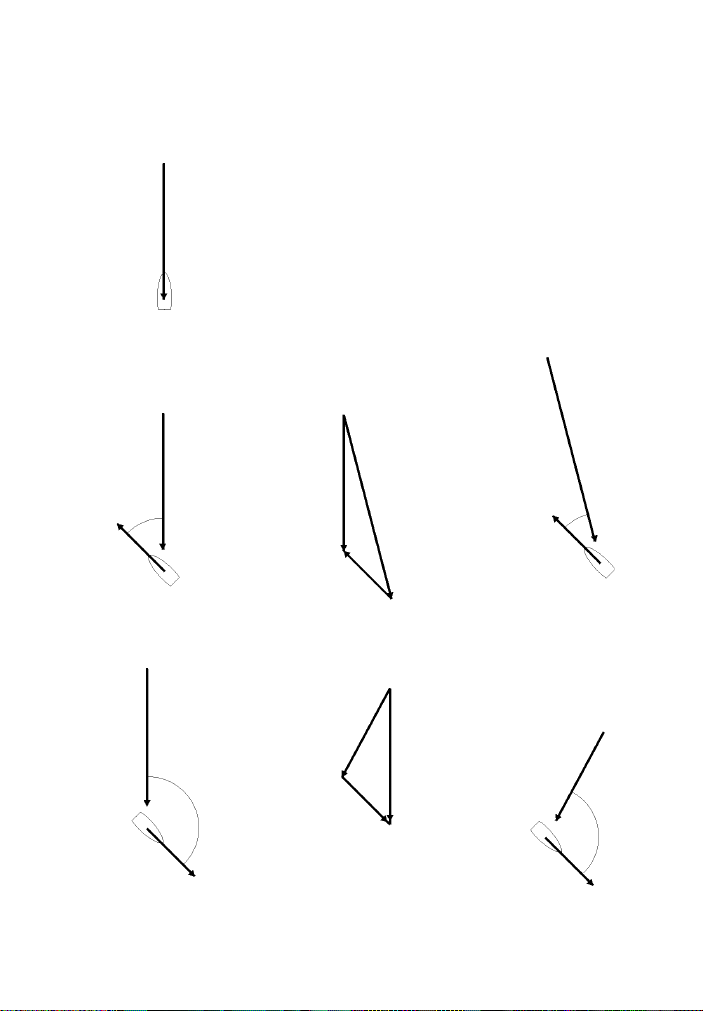
3-2 Set wind direction pointer type
The wind direction pointer can be set to one of five
types (see right). Type 1 is the default.
Types 1, 2 and 3 simulate wind vanes, and
have a black spot in the centre. The thinner
part points to where the wind is coming from.
Types 4 and 5 point to where the wind is
coming from.
T o set the pointer type:
1 Press + several times until the Pointer
Type screen is displayed:
Pointer
type 1
2 Press or to set the pointer type.
3 Press .
3-3 Set wind direction damping
Wind turbulence, gusts and mast motion cause the
wind direction to fluctuate. To give a stable reading,
the WIND 3100 calculates the wind direction by
measuring the direction several times and averaging
the measurements. The wind direction damping
value ranges from 1 to 5:
A lower value averages readings over a shorter
period of time. This gives the most accurate
direction but has the most fluctuations.
A higher value averages readings over a longer
period of time. This gives the most stable
direction but will ignore some true changes in
direction.
Note : The damping affects the numeric wind
direction, not the pointer. Set the wind direction
damping to the lowest value which gives a stable
numeric wind direction. Values of 1, 2, 3, 4 and 5
average readings over a time period of 6, 12, 18, 24
and 30 seconds respectively.
To set the damping:
8
Wind from 30° to starboard, pointer type 1
Wind
direction
Wind from 30° to port, pointer type 2
Wind direction
Wind from 150° to port, pointer type 3
Wind direction
Wind from 30° to starboard, pointer type 4
Wind
direction
Wind from 120° to starboard, pointer type 5
Wind
direction
NAVMAN
WIND 3100 Installation and Operation Manual
Page 9
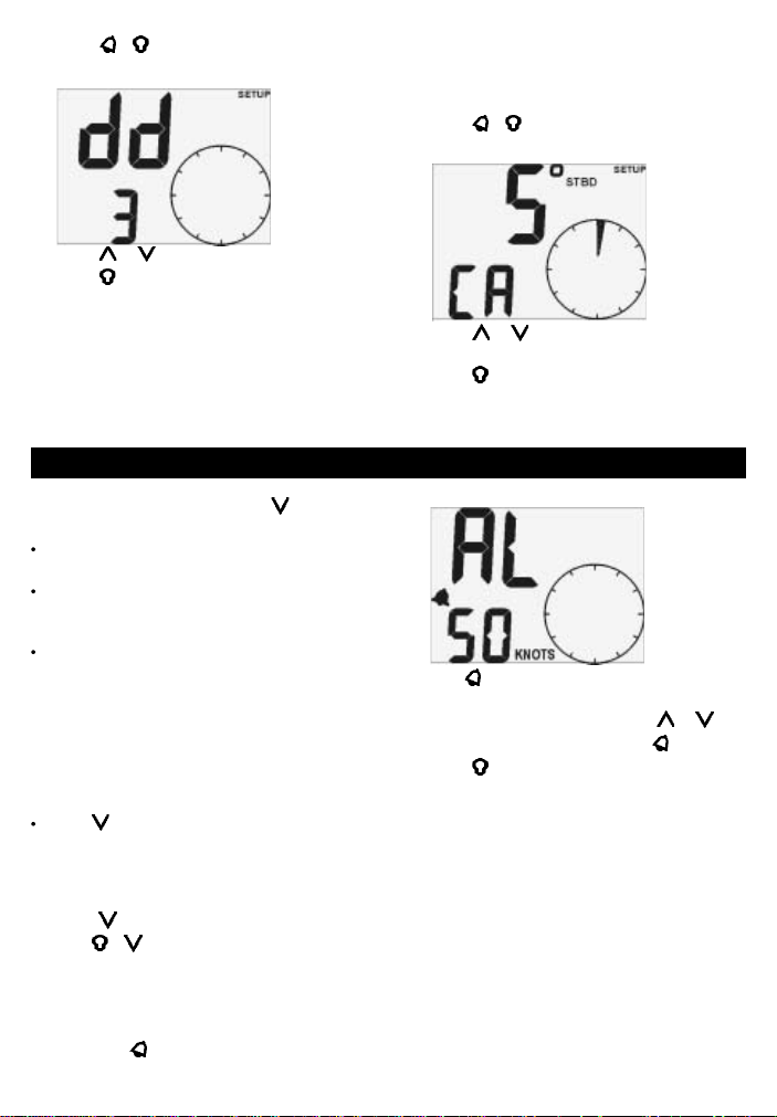
1 Press + to display the Wind Direction
Damping screen:
Damping
equals 3
2 Press
3 Press
or to change the damping.
.
3-4 Calibrate wind alignment
You will need to calibrate the wind alignment if you
believe that the displayed wind direction is inaccurate
or, at installation, if the masthead arm is not parallel
to the centre line of the boat:
1 You must know what the correct wind direction
is. The easiest way for a boat with a motor is to
travel at maximum speed when there is no
wind. The correct wind direction is then from
ahead, 0°.
2 Press
3 Press
4 Press
+ several times until the Calibrate
Wind Alignment screen is displayed:
Wind
direction is 5°
to starboard
or to change the displayed wind
direction to the correct value.
.
4 Wind speed, VMG
The WIND 3100 can display one of three speeds in
the bottom part of the screen. Press
times to select:
WIND SPEED: The wind speed, apparent or
true (see section 3).
MAX SPEED: The maximum apparent wind
speed since MAX SPEED was reset or the unit
was switched on.
VMG: The component of boat speed parallel to
the wind.
True wind speed and VMG are only displayed if the
WIND 3100 is connected to a speed instrument or a
NAVMAN GPS.
4-1 Set wind speed units
The wind speed units can be selected to be KNOTS
or M/S:
Hold until the units change.
Note: VMG is always shown in knots.
4-2 Reset maximum wind speed
Resetting starts calculating a new maximum:
1 Press
2 Hold
until MAX speed is displayed.
+ for two seconds.
4-3 Set wind speed alarm
The wind speed alarm sounds if the alarm is turned
on and the apparent wind speed becomes equal to
or more than the wind speed alarm value. If the alarm
sounds, press to mute it.
NAVMAN
WIND 3100 Installation and Operation Manual
one or more
To set the alarm value or turn the alarm on or off:
Wind speed
value 50 kts
Alarm is On
1 Hold
2 To change the alarm value, press
3 To turn the alarm on or off, press
4 Press
for two seconds to display the Wind
Speed Alarm screen:
or .
.
.
4-4 Calibrate wind speed
The unit is factory calibrated and should not normally
need calibrating, however you should calibrate it if
you believe that the displayed wind speed is
inaccurate:
1 You must know what the correct wind speed is.
The easiest way for a boat with a motor is to
travel at maximum speed when there is no
wind; the correct wind speed is then equal to
the boat speed. Find the boat speed from a
speed instrument in the boat or in another boat
travelling at the same speed.
9
Page 10

2 Press
+ several times until the Calibrate
Wind Speed screen is displayed (see right).
3 Press
or to change the displayed wind
speed to the correct value.
4 Press
.
5 Steer to wind
The steer to wind function gives steering instructions
to sail at a constant angle to the apparent wind. The
WIND 3100 automatically calculates the correct
instructions for port or starboard tacks.
To start steering to wind, press
displayed. The display shows:
1 The required steering angle to the apparent
wind (to set the required steering angle, see
section 5-1).
2 A direction arrow showing which way to steer
to reach the required steering angle.
3 The steering error (the difference between the
required steering angle and the actual steering
angle) is shown on the circular display:
Steer to wind examples
The required steering angle is 40° and the boat is at
30° to the apparent wind. The steering error is 10°.
The boat should turn 10° to port. The steering
resolution is 1° and so 10 segments of the circular
display are on:
Required
steering angle
40°
Steering
correction
10° to port
Actual
steering
angle
30°
until STEER is
Wind
direction
Wind speed
The top two segments are always on
The greater the steering error, the more
segments turn on
The steering resolution determines how
many segments turn on. The number of
segments that turn on is the steering error
divided by the steering resolution (to set
the steering resolution, see section 5-2).
If the boat should steer to port, then
segments to the right of centre turn on
If the boat should steer to starboard, then
segments to the left of centre turn on.
The required steering angle is 40° and the boat is at
70° to the apparent wind. The steering error is 30°.
The boat should turn 30° to starboard. The steering
resolution is 5° and so 6 segments of the circular
display are on:
Required
steering angle
40°
Steering
correction
30° to starboard
Wind
direction
Actual
steering
angle
70°
Required steering angle
10
Direction arrow
(way to steer)
Steering error ,
10 segments
are on
Required steering angle
NAVMAN
WIND 3100 Installation and Operation Manual
Direction arrow
(way to steer)
Steering error ,
6 segments
are on
Page 11

5-1 Set required steering angle
The required steering angle is the required angle
between the boat direction and the apparent wind
direction:
1 While steering to wind, press + ; the
required steering angle flashes:
Required
steering
angle is 45°
2 Press
3 Press
or to change the required steering
angle. The range is 0
.
° to 150°.
6 Systems of several instruments
Several NAVMAN instruments can be connected
together to share data. There are two ways of connecting
instruments together, NavBus or NMEA.
6-1 NavBus
NavBus is a NAVMAN proprietary system that allows
systems of multiple instruments to be built using a single
set of transducers. When instruments are connected
by NavBus:
If you change the units, alarms or calibration in
one instrument, then the values will automatically
change in all other instruments of the same type.
Each instrument can be assigned to a group of
instruments (see section 1, 8-2, step 3). If you
change the backlight in an instrument in group 1,
2, 3 or 4 then the backlight will automatically
change in the other instruments in the same
group. If you change the backlight in an
instrument in group 0 then no other instruments
are affected.
If an alarm sounds, mute it by pressing on any
instrument which can display that alarm.
NavBus and the WIND 3100
If the WIND 3100 does not have a masthead unit
fitted then the unit will automatically take wind
direction and speed readings from another
instrument, via NavBus, if the data is available.
For more information, refer to the NavBus
Installation and Operation manual.
If a masthead unit is not fitted to the unit and the
NAVMAN
WIND 3100 Installation and Operation Manual
5-2 Set steering resolution
In steer to wind, the circular pointer shows the steering
correction. The steering resolution is a number from 1
to 5 that sets the number of degrees of steering error
that each segment represents (see examples on
previous page).
Use a smaller steering resolution for more exact sailing.
To set the steering resolution:
1 Press
+ several times until the Steering
Resolution screen is displayed:
Steering
resolution
is 5°
2 Press
3 Press
or to change the resolution.
.
corresponding external data is not available then
the displayed value will be dashes (— —).
To display true wind speed, true wind direction
and VMG, the WIND 3100 must be connected to
an instrument that outputs boat speed. Typical
instruments that output boat speed are:
A GPS receiver (outputs boat speed over
ground).
A NAVMAN SPEED 3100, which uses a
paddlewheel transducer (outputs boat speed
through water).
Note: If there is a current, these two speeds are
different.
You must select which type of boat speed the WIND
3100 will use (see section 3.1 and 8-2, step 2).
6-2 NMEA
NMEA is an industry standard, but is not as flexible
as NavBus as it requires dedicated connections
between instruments. Wind, speed and direction data
are output by the WIND 3100 and can be read and
displayed by the NAVMAN REPEAT 3100 or other
NMEA instruments. The WIND 3100 can receive
NMEA boat speed data:
RMC or VTG from any compatible GPS
instrument (speed over ground)
VHW from any compatible instrument with a
paddlewheel speed transducer (speed through
water).
Y ou must select which type of boat speed the WIND
3100 will use (see section 3-1, 8-2, step 2).
11
Page 12

7 WIND 3100 hardware
7-1 What comes with your WIND 3100
Standard configuration:
WIND 3100 unit with protective cover.
Masthead unit.
30 m Masthead cable.
Masthead cable junction box.
Warranty card.
Mounting template.
This Installation and Operation Manual.
7-2 Other parts required
One or more 3100 series instruments will be
connected to the boat 12 V DC power supply via:
An accessory switch to turn the instruments on
and off.
A fuse. Use a 1 A fuse for between one and five
instruments.
Optional external beepers or lights can be fitted. The
WIND 3100 output is switched to ground, 30 V DC
and 250 mA maximum. If the beepers and lights
require more than 250 mA, fit a relay.
For systems of several instruments, wiring and
connectors are required (see section 6 or the NavBus
Installation and Operation manual).
In order to display true wind speed and direction and
VMG, the WIND 3100 must be connected to an
instrument that outputs speed (see section 6).
The WIND 3100 is usually used with the supplied
masthead unit. However, the unit can take readings
from another NAVMAN wind instrument, in which
case the masthead unit does not need to be fitted
(see section 6-1).
7-3 Accessories
These accessories are available from your NAVMAN dealer.
Replacement
masthead unit
12
Masthead unit windcup
NAVMAN
NavBus junction box
(see section 6)
WIND 3100 Installation and Operation Manual
Page 13

8 Installation and setup
Correct installation is critical to the performance of
the unit. It is vital to read this section of the manual
and the documentation that comes with the other
parts before starting installation.
The WIND 3100 can:
Drive external beepers or lights for the alarm.
Send and receive data from other NAVMAN
instruments connected via NavBus. Settings
for alarms, units, calibration and backlighting
are shared (see section 6-1).
Send and receive NMEA data to and from other
instruments (see section 6-2).
Warnings
The unit is waterproof from the front. Protect the rear
of the unit from water, or else water might enter the
breathing hole and damage the unit. The warranty
does not cover damage caused by moisture or water
entering the back of the unit.
The cable up the mast to the masthead unit must
run in conduit.
Ensure that any holes that you cut will not
weaken the boat or the mast. If in doubt,
consult a qualified boat builder or marine
engineer.
8-1 Installation
WIND 3100 display unit
1 Choose a location for the display unit that is:
Easily seen and protected from damage.
At least 100 mm from a compass and at
least 500 mm from a radio or radar
antenna.
Away from engines, fluorescent lights, and
power inverters.
Accessible from behind; the minimum
clearance required at the back is 50 mm
(2") (see mounting diagram).
With the back of the unit protected from
moisture.
2 The unit must mount on a flat panel which is
less than 20 mm (0.75") thick. Stick the
mounting template in place. Drill a 50 mm (2")
fixing hole through the centre hole in the
template. Note that the template allows space
around the unit for the protective cover.
3 Remove the fixing nut from the back of the unit.
Insert the stud at the back of the unit through the
mounting hole. Hand tighten the fixing nut.
NAVMAN
WIND 3100 Installation and Operation Manual
Side view of display unit mounting:
Fixing hole
50 mm (2")
Masthead unit
Plan the installation. Read through these instructions
before you install the masthead unit and plan where
you will fit the mounting block and where you will
drill the cable holes in the mast. It is usually easiest
to install the masthead unit when the rig is off the
boat.
1 The mounting block is at one end of the 30 m
(90 ft) masthead cable. Fit the mounting block
on top of the mast:
Use the self-tapping screws provided.
2 Drill an 8 mm (5/16") hole at the top of the
mast close to the mounting block for the cable
to enter the mast. Do not install the masthead
cable yet.
3 Drill an 8 mm (5/16") hole at the bottom of the
mast at a convenient place for the cable to exit
the mast. You will fit the cable junction box
close to this hole; it should be in a dry place
and not in the bilge.
4 Calculate how long the cable from the
masthead mounting block to the cable junction
20 mm (0.75")
maximum thickness
Display
unit
Cables Clearance
50 mm (2") minimum
With the base of the block horizontal.
With the fitting for the masthead arm facing
forward, parallel to the centre line to within
a few degrees (if the arm does not face
exactly forward, the wind direction will need
to be aligned, see section 3-4).
Arm faces forward
Forward
Fixing nut
Cables
13
Page 14

box needs to be. Allow extra length for
terminating the cable in the junction box. Cut
the masthead cable to this length from the
mounting block. Do not throw away the other
piece of cable.
5 Lead the bare end of the masthead cable into
the hole at the top of the mast, down the
conduit in the mast and out the hole at the
bottom of the mast. Fit a strain relief clamp or
cable tie to the cable at the mast top. Fill both
cable holes in the mast with sealant.
6 Feed the end of the cable through a gland on
the cable junction box. Strip the cable jacket off
and terminate the wires on the terminal block
supplied.
7 Take the piece of masthead unit cable that you
cut off earlier and connect the cable into the
back of the WIND 3100 display unit. Run the
cable between the display unit and the cable
junction box:
Keep the cable away from other cables,
engines, fluorescent lights and power
inverters
Secure the cable at regular intervals.
8 Cut the cable to length, allowing extra length
for terminating the cable in the joining box.
Feed the end of the cable through the other
gland on the cable junction box. Strip the cable
jacket off and terminate wires on the terminal
block, matching the wire colours.
9 Screw the lid on the junction box and screw the
box in place on a panel.
10 Fit the wind cups to the shaft on the masthead
unit using the allen key supplied.
Installed Masthead Unit:
Cable
Forward
Mast
Cable strain relief
Hole in mast,
fill with sealant
Cable runs
down inside
of mast in
conduit
Hole in mast,
fill with sealant
Cable junction box
Power/data wiring
1 Wire the display unit power/data cable:
The unit requires 12 V DC power. Fit a
power switch and fuse to the power supply
or power the unit from a fused auxiliary
switch. The fuse should be 1 A for up to five
instruments.
If the external beepers and lights require
more than 250 mA DC total, fit a relay.
Cable to
Wind 3100
Fit
wind
cups
Arm
Fit mounting block
to mast top (Step 1)
Plug arm
into block
11 Attach the arm to the mounting block:
Plug the arm into the mounting block.
Screw the sleeve on the arm onto the
mounting block.
Screw sleeve
onto block
14
Mast
Masthead
unit cable
NAVMAN
Black
Red
Green
Yellow
White
Orange
Blue
Switch
External beepers or
lights (optional)
NMEA in (GPS, optional)
NMEA out (optional)
}
NavBus (optional)
WIND 3100 Installation and Operation Manual
Fuse
12 V DC
power
Page 15

A single unit can be wired as shown below:
With several instruments, use the optional
junction boxes to simplify wiring, as shown
below:
i Press + several times until the
Speed Mode screen is displayed:
Group 1
Junction box
Power & data
connections
Power/data cables
Group 2
NavBus cable
Junction box
Power & data
connections
Power/data cable
For information on how to connect NavBus and
to use junction boxes, refer to the NavBus
Installation and Operation manual.
2 Tape or cover any unused wires or connectors
to protect them from water and keep them from
shorting together.
8-2 Setup
1 Take the boat for a trial run to check that all the
instruments work correctly.
2 To displayVMG, true wind speed and direction,
the WIND 3100 must be connected to an
instrument that outputs boat speed. If the
WIND 3100 is connected to an instrument that
outputs speed through water and to an
instrument that outputs speed over ground,
then you can select which the WIND 3100 will
use (see sections 3-1 and 6):
Mode is
or
Group is 3
ii Press
or to change the mode to
(Speed over ground) or (boat speed
through water).
iii Press
.
3 If the unit is part of a system of 3100 series
instruments connected by NavBus, set the
backlight group number (see section 6-1):
i Press
+ several times until the
Backlight Group screen is displayed:
ii Press
or to set the backlight group
number.
iii Press
.
4 Set:
The speed units (see section 4-1) .
The pointer type (see section 3-2).
5 Calibrate if required:
Wind alignment (see section 3-4).
Wind speed (see section 4-4).
8-3 Resetting to factory defaults
All settings may be reset to the manufacturer’s
default settings (see below).
Wind speed units ................................ knots
Pointer type................................................. 1
Direction damping ......................................2
Steering angle ......................................... 40°
Steer angle resolution ..........2° per segment
Wind speed alarm .................................... Off
SIMULATE mode ......................................Off
Backlight Level ...........................................0
Backlight Group.......................................... 1
Boat Speed Input ......................................
NAVMAN
WIND 3100 Installation and Operation Manual
T o reset to factory defaults:
1 Turn the power off.
2 Hold down + while you turn the power
on and continue to hold the keys down for at
least five seconds.
15
Page 16

Appendix A - Specifications
Physical
Case size 111 mm (4.4") square.
LCD display 82 mm (3.2") wide, 61 mm (2.4")
high; twisted nematic.
LCD digits 30 mm (1.2") high on top line,
20 mm (0.8") high on bottom line.
Four operator keys, laser etched.
Backlighting for display and keys, amber, four
levels and off (the key backlight does not turn off).
Operating temperature 0 to 50°C (32 to 122°F).
Power Cable length 1m (3.25 ft).
Masthead unit cable length 30 m (99 ft).
Electrical
Power supply 10.5 to 16.5 V DC, 20 mA without
backlighting, 120 mA with full backlighting and
transducer.
External beeper or light output, switched to
ground, 30 V DC and 250 mA maximum.
Wind
Wind direction, true and apparent: Range 0 to
180°, port or starboard.
Wind speed, true and apparent: Range 0 to 199
knots (0 to 102 m/s).
Maximum apparent wind speed.
Apparent wind speed alarm.
Appendix B - Troubleshooting
This troubleshooting guide assumes that you have
read and understood this manual.
It is possible in many cases to solve difficulties
without having to send the unit back to the
manufacturer for repair. Please follow this
troubleshooting section before contacting the
nearest NAVMAN dealer .
There are no user serviceable parts. Specialized
methods and testing equipment are required to
ensure that the unit is reassembled correctly and is
waterproof. Repairs to the unit must only be carried
out by a service centre approved by Navman NZ
Limited. Users who service the unit themselves will
void the warranty.
More information can be found on our website:
www.navman.com
1 Unit will not turn on:
a Fuse blown or circuit breaker tripped.
b Battery voltage is outside the range 10.5 to
16.5 V DC.
c Power/data cable damaged.
16
Calibration
Wind speed and wind direction (alignment) can
be calibrated.
Interfaces
NavBus connection to other NAVMAN
instruments.
NMEA 0183 outputs: MWV, VPW; inputs RMC,
VHW, VTG.
Standards compliance
EMC compliance
USA (FCC): Part 15 Class B.
Europe (CE): EN50081-1, EN50082-1
New Zealand and Australia (C Tick):
Environment: IP66 from front when correctly
mounted.
Power/data cable wires
Wire Signal
Red Power positive, 12 V DC, 120 mA
Black Power negative, NMEA common
Green External beeper or light out, switched to
Orange NavBus +
Blue NavBus White NMEA out
Y ellow NMEA in
2 Wind speed or direction readings wrong or
3 The word SIM flashes at top, right of screen,
4 The display fogs:
maximum
ground, 30 V DC and 250 mA max.
erratic:
a Wind speed calibration is incorrect (see
section 4-4).
b Wind direction alignment is incorrect (see
section 3-4).
c Masthead unit cable unplugged or
damaged.
d Masthead unit is damaged or fouled.
e Interference from electrical noise. Review
installation.
values displayed are unexpected:
a Unit is in simulate mode (see section 2-4).
a Moist air has entered the breathing tube at
the rear of the unit. Air the boat or run unit
with backlight fully on.
b Water has entered the breathing tube.
Return unit for service.
NAVMAN
WIND 3100 Installation and Operation Manual
AS-NZS 3548.
Page 17

Appendix C - How to contact us www.navman.com
NORTH AMERICA
NAVMAN USA INC.
18 Pine St. Ext.
Nashua, NH 03060.
Ph: +1 603 577 9600
Fax: +1 603 577 4577
e-mail: sales@navmanusa.com
OCEANIA
New Zealand
Absolute Marine Ltd.
Unit B, 138 Harris Road,
East Tamaki, Auckland.
Ph: +64 9 273 9273
Fax: +64 9 273 9099
e-mail:
navman@absolutemarine.co.nz
Australia
NAVMAN AUSTRALIA PTY
Limited
Unit 6 / 5-13 Parsons St,
Rozelle, NSW 2039, Australia.
Ph: +61 2 9818 8382
Fax: +61 2 9818 8386
e-mail: sales@navman.com.au
SOUTH AMERICA
Argentina
HERBY Marina S.A.
Costanera UNO,
Av Pte Castillo Calle 13
1425 Buenos Aires, Argentina.
Ph: +54 11 4312 4545
Fax: +54 11 4312 5258
e-mail:
herbymarina@ciudad.com.ar
Brazil
REALMARINE
Estrada do Joa 3862,
CEP2611-020,
Barra da Tijuca, Rio de Janeiro,
Brasil.
Ph: +55 21 2483 9700
Fax: +55 21 2495 6823
e-mail:
vendas@marinedepot.com.br
Equinautic Com Imp Exp de
Equip Nauticos Ltda.
Av. Diario de Noticias 1997 CEP
90810-080, Bairro Cristal, Porto
Alegre - RS, Brasil.
Ph: +55 51 3242 9972
Fax: +55 51 3241 1134
e-mail:
equinautic@equinautic.com.br
NAVMAN
WIND 3100 Installation and Operation Manual
ASIA
China
Peaceful Marine Electronics Co. Ltd.
Hong Kong, Guangzhou,
Shanghai, Qindao, Dalian.
E210, Huang Hua Gang Ke Mao
Street, 81 Xian Lie Zhong Road,
510070 Guangzhou, China.
Ph: +86 20 3869 8784
Fax: +86 20 3869 8780
e-mail:
sales@peaceful-marine.com
Website:
www.peaceful-marine.com
Korea
Kumho Marine Technology Co. Ltd.
# 604-816, 3F, 1117-34,
Koejung4-Dong, Saha-ku
Pusan, Korea
Ph: +82 51 293 8589
Fax: +82 51 294 0341
e-mail: info@kumhomarine.com
Website:
www.kumhomarine.com
Malaysia
Advanced Equipment Co.
43A, Jalan Jejaka 2, Taman
Maluri, Cheras 55100, Kuala Lumpur.
Ph: +60 3 9285 8062
Fax: +60 3 9285 0162
e-mail: ocs@pc.jaring.my
Singapore
RIQ PTE Ltd.
Blk 3007, Ubi Road 1,
#02-440, Singapore 408701
Ph: +65 6741 3723
Fax: +65 6741 3746
HP: +65 9679 5903
e-mail: riq@postone.com
Thailand
Thong Electronics (Thailand)
Company Ltd.
923/588 Thaprong Road,
Mahachai,
Muang, Samutsakhon 74000,
Thailand.
Ph: +66 34 411 919
Fax: +66 34 422 919
e-mail: thonge@cscoms.com
Vietnam
Haidang Co. Ltd.
16A/A1E, Ba thang hai St.
District 10, Hochiminh City.
Ph: +84 8 86321 59
Fax: +84 8 86321 59
e-mail:
sales@haidangvn.com
Website: www.haidangvn.com
MIDDLE EAST
Lebanon and Syria
Letro, Balco Stores,
Moutran Street, Tripoli
VIA Beirut.
Ph: +961 6 624512
Fax: +961 6 628211
e-mail: balco@cyberia.net.lb
United Arab Emirates
Kuwait, Oman & Saudi Arabia
AMIT, opp Creak Rd.
Baniyas Road, Dubai.
Ph: +971 4 229 1195
Fax: +971 4 229 1198
e-mail: mksq99@email.com
AFRICA
South Africa
Pertec (Pty) Ltd Coastal,
Division No.16 Paarden Eiland Rd.
Paarden Eiland, 7405
Postal Address: PO Box 527,
Paarden Eiland 7420
Cape Town, South Africa.
Ph: +27 21 511 5055
Fax: +27 21 511 5022
e-mail: info@kfa.co.za
EUROPE
France, Belgium and
Switzerland
PLASTIMO INTERNATIONAL
15, rue Ingénieur Verrière,
BP435,
56325 Lorient Cedex.
Ph: +33 2 97 87 36 36
Fax: +33 2 97 87 36 49
e-mail: plastimo@plastimo.fr
Website: www.plastimo.fr
Germany
PLASTIMO DEUTSCHLAND
15, rue Ingénieur Verrière
BP435
56325 Lorient Cedex.
Ph: +49 6105 92 10 09
+49 6105 92 10 10
+49 6105 92 10 12
Fax: +49 6105 92 10 11
e-mail:
plastimo.international@plastimo.fr
Website: www.plastimo.de
Italy
PLASTIMO ITALIA
Nuova Rade spa, Via del Pontasso 5
I-16015 CASELLA SCRIVIA (GE).
Ph: +39 1096 8011
Fax: +39 1096 8015
e-mail: info@nuovarade.com
Website: www.plastimo.it
Holland
PLASTIMO HOLLAND BV.
Industrieweg 4,
2871 JE SCHOONHOVEN.
Ph: +31 182 320 522
Fax: +31 182 320 519
e-mail: info@plastimo.nl
Website: www.plastimo.nl
United Kingdom
PLASTIMO Mfg. UK Ltd.
School Lane - Chandlers Ford
Industrial Estate,
EASTLEIGH - HANTS S053 ADG.
Ph: +44 23 8026 3311
Fax: +44 23 8026 6328
e-mail: sales@plastimo.co.uk
Website: www.plastimo.co.uk
Sweden, Denmark or Finland
PLASTIMO NORDIC AB.
Box 28 - Lundenvägen 2,
47321 HENAN.
Ph: +46 304 360 60
Fax: +46 304 307 43
e-mail: info@plastimo.se
Website: www.plastimo.se
Spain
PLASTIMO ESPAÑA, S.A.
Avenida Narcís Monturiol, 17
08339 VILASSAR DE DALT,
(Barcelona).
Ph: +34 93 750 75 04
Fax: +34 93 750 75 34
e-mail: plastimo@plastimo.es
Website: www.plastimo.es
Other countries in Europe
PLASTIMO INTERNATIONAL
15, rue Ingénieur Verrière
BP435
56325 Lorient Cedex, France.
Ph: +33 2 97 87 36 59
Fax: +33 2 97 87 36 29
e-mail:
plastimo.international@plastimo.fr
Website: www.plastimo.com
REST OF WORLD /
MANUFACTURERS
NAVMAN NZ Limited
13-17 Kawana St. Northcote.
P.O. Box 68 155 Newton,
Auckland, New Zealand.
Ph: +64 9 481 0500
Fax: +64 9 480 3176
e-mail:
marine.sales@navman.com
Website:
www.navman.com
79
Page 18
Made in New Zealand
MN000134 1951320B
WIND 3100
Lon 174° 44.535’E
Lat 36° 48.404’S
80
20
NAVMAN
NAVMAN
NAVMAN
WIND 3100 Installation and Operation Manual
WIND 3100 Installation and Operation Manual
 Loading...