

Page 1

WIND
RESET
NAVMAN
NAVMAN
Page 2

Page 3

NAVMAN W100
ENGLISH .................................................................................... 3
FRANÇAIS – FRENCH ............................................................ 13
DEUTSCH – GERMAN ............................................................. 23
NEDERLANDS – DUTCH ........................................................ 33
SVENSKA – SWEDISH............................................................ 43
ESPAÑOL – SPANISH.............................................................. 53
DEUTSCH – GERMAN ............................................................. 23
ENGLISH .................................................................................... 3
ESPAÑOL – SPANISH.............................................................. 53
FRANÇAIS – FRENCH ............................................................ 13
NEDERLANDS – DUTCH ........................................................ 33
SVENSKA – SWEDISH............................................................ 43
Page 4

Page 5

3NA VMAN W100 User Manual
Contents
Specification . . . . . . . . . . . . . . . . . . . . . . . . . . . . . . . . . . . . . . . . . . . . . . . . . . . . . . . . . 4
Installation . . . . . . . . . . . . . . . . . . . . . . . . . . . . . . . . . . . . . . . . . . . . . . . . . . . . . . . . . . . 5
Location . . . . . . . . . . . . . . . . . . . . . . . . . . . . . . . . . . . . . . . . . . . . . . . . . . . . . . . . . . 5
Mounting . . . . . . . . . . . . . . . . . . . . . . . . . . . . . . . . . . . . . . . . . . . . . . . . . . . . . . . . . . 5
Wiring Connection . . . . . . . . . . . . . . . . . . . . . . . . . . . . . . . . . . . . . . . . . . . . . . . . . . 6
Multiple Instruments . . . . . . . . . . . . . . . . . . . . . . . . . . . . . . . . . . . . . . . . . . . . . . . . . 6
Installation of the NAVMAN W100 Mast Head Transducer . . . . . . . . . . . . . . . . . . . . . 7
Calibration Procedures . . . . . . . . . . . . . . . . . . . . . . . . . . . . . . . . . . . . . . . . . . . . . . . . 8
Linearisation of the Wind Sensor and Instrument . . . . . . . . . . . . . . . . . . . . . . . . . . 8
Alignment of the Wind Vane and Display . . . . . . . . . . . . . . . . . . . . . . . . . . . . . . . . . 8
Wind Speed Calibration . . . . . . . . . . . . . . . . . . . . . . . . . . . . . . . . . . . . . . . . . . . . . . 8
Wind Speed . . . . . . . . . . . . . . . . . . . . . . . . . . . . . . . . . . . . . . . . . . . . . . . . . . . . . . . 8
Alignment . . . . . . . . . . . . . . . . . . . . . . . . . . . . . . . . . . . . . . . . . . . . . . . . . . . . . . . . . 8
Linearisation . . . . . . . . . . . . . . . . . . . . . . . . . . . . . . . . . . . . . . . . . . . . . . . . . . . . . . . 8
Operation . . . . . . . . . . . . . . . . . . . . . . . . . . . . . . . . . . . . . . . . . . . . . . . . . . . . . . . . . . . . 9
Backlighting On / Off . . . . . . . . . . . . . . . . . . . . . . . . . . . . . . . . . . . . . . . . . . . . . . . . . 9
Wind Speed Alarm On/Off. . . . . . . . . . . . . . . . . . . . . . . . . . . . . . . . . . . . . . . . . . . . . 9
Set Wind Speed Alarm . . . . . . . . . . . . . . . . . . . . . . . . . . . . . . . . . . . . . . . . . . . . . . . 9
True or Apparent Wind Display. . . . . . . . . . . . . . . . . . . . . . . . . . . . . . . . . . . . . . . . . 9
Select Speed Function . . . . . . . . . . . . . . . . . . . . . . . . . . . . . . . . . . . . . . . . . . . . . . 10
Select Speed Units . . . . . . . . . . . . . . . . . . . . . . . . . . . . . . . . . . . . . . . . . . . . . . . . . 10
Reset Maximum Wind Speed . . . . . . . . . . . . . . . . . . . . . . . . . . . . . . . . . . . . . . . . . 10
Troubleshooting Chart . . . . . . . . . . . . . . . . . . . . . . . . . . . . . . . . . . . . . . . . . . . . . . . . 11
W100/ENG/1C
Page 6

4 NA VMAN W100 User Manual
Specification
• Power Supply
10.7 to 16.6 VDC, 30mA nominal, 40mA with
backlight on.
• Operating temperature
0°C to 45°C.
• Size of display
112 x 112 x 24mm (4.4 x 4.4 x 1”), overall
depth 35mm (1.4”) behind panel.
• Display type.
Twisted Nematic (TN) grey background,
0°C to +70°C.
• Illumination
Red LED switchable from key pad.
• RF interference
Less than 6 dB maximum quieting on any
marine radio channel with 3 dB gain antenna
within 1 metre of instrument display head
(European EC specifications).
• Wind Direction
Apparent and true 180 degrees to port and
starboard.
• Wind speed
0 to 99 knots, or 0 to 50 m/sec with
maximum wind speed recording.
• Alarm
Wind speed alarm user settable value.
• VMG display
Displayed in 0.1 steps to 19.9 knots and 1.0
steps above 20 knots.
• NMEA input (for VMG and T rue Wind
Data calculation)
Accepts VHW sentence from NAVMAN
S100 speed log or other instrument with
NMEA output.
• NMEA output
NMEA 0183 format VWT, VWR, MWV, VPW
for NAVMAN R100 system repeater or
other NMEA compatible instrument. Short
circuit protected. Drive capability for up to
four NMEA receivers.
• Transducer cables.
5 pin Fuji connector for wind mast head
transducer, 5 conductor cable for NMEA
input, output and power connections.
• Transducer
Lightweight weatherproof type with 30
meters of cable. Electronic sine cosine
output.
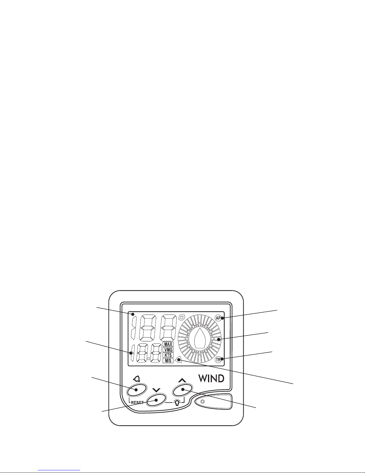
Display is backlit for
Night Operation
Displays wind speed,
maximum wind speed
or VMG
Maximum wind
speed On/Off
Selects function on lower section of display
Wind Speed, Max Wind Speed or VMG
Selects true or apparent
Wind Speed and Direction
Indicates apparent Wind
Speed and Direction
Indicates direction in
10 degree steps
Indicates true Wind
Speed and Direction
Wind Speed
alarm
Page 7

5NA VMAN W100 User Manual
Installation
Location
The NAVMAN W100 is designed for above or
below deck installation. Select a position that is:
• At least 300mm from a compass
• At least 500mm from any radio
• Easy to read by the helmsman and crew
• Protected from physical damage
• Accessible to electrical cable connections
112mm
(4.4”)
4.5mm
(1.75”)
30mm
(1.2”)
112mm
(4.4”)
24mm
(1”)
56mm
(2.2”)
35mm
(1.4”)
Mounting
The mounting surface must be flat. Use the
template to set the centre of the fixing hole.
• Drill a 32mm (1.25”) diameter mounting hole
through the bulkhead.
• Remove the fixing nut. Peel the protective
paper off the foam gasket and attach the
gasket to the rear of the instrument.
• Insert the instrument through the bulkhead.
Hand tighten the nut and then finally tighten
with a spanner. Do not over tighten so that
the water sealing ability of the gasket is
damaged.
Page 8

6 NA VMAN W100 User Manual
Green
Black
Blue
Red
NMEA data to Wind (from Speed/Log)
Fuji
Plug &
Socket
Wind
Transducer
1A Fuse
+12 VDC
Ground
NMEA output to repeater
Wiring Connection
• Keep electrical and transducer cables away
from alternator or other noise generating
electrical cables. Avoid connecting the
instrument to power circuits that share
loads with ignition, alternators, inverters and
radio transmitters. Electrical power supply
connections should always be as short as
possible.
• Connect the red wire to the positive supply
via a 1 amp fuse or a 1 amp circuit breaker.
Connect the black wire to the electrical
ground. A 1 amp fuse will provide protection
for up to five 100 series instruments.
• Connect the 5 pin Fuji connector to the
wind transducer cable connector. Do not cut
or shorten the transducer cable. Extension
cables are available if the transducer cable
is too short.
• If you are not interfacing to a NAVMAN
S100 speed instrument or NAVMAN R100
repeater or you do not intend to provide
NMEA data to another instrument then
insulate the bare unused wires in the end of
the five core cable.
Green
Black
Blue
Red
Black
Blue
Red
1A Fuse
+12 VDC
Ground
NMEA speed data to repeater
NMEA data to Wind
NMEA wind data to repeater
Fuji
Plug &
Socket
Wind
Transducer
Speed
Transducer
Multiple Instruments
The model NAVMAN W100 wind
instrument can be connected to
the model NAVMAN S100 speed
instrument to display true wind
speed direction and speed VMG
data on the NAVMAN W100 display .
The NAVMAN W100 may also be
connected to the NAVMAN R100
system repeater or to any other
instrument that will accept standard
NMEA 0183 data.
Page 9
7NA VMAN W100 User Manual
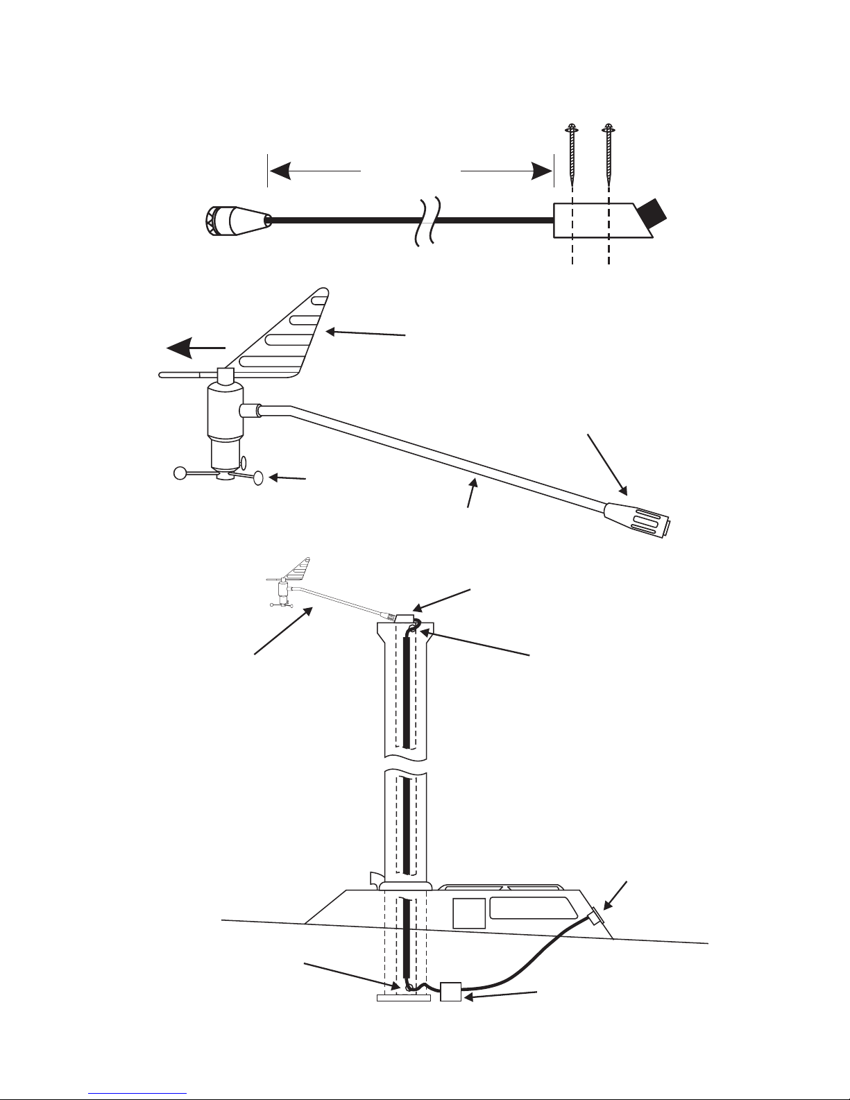
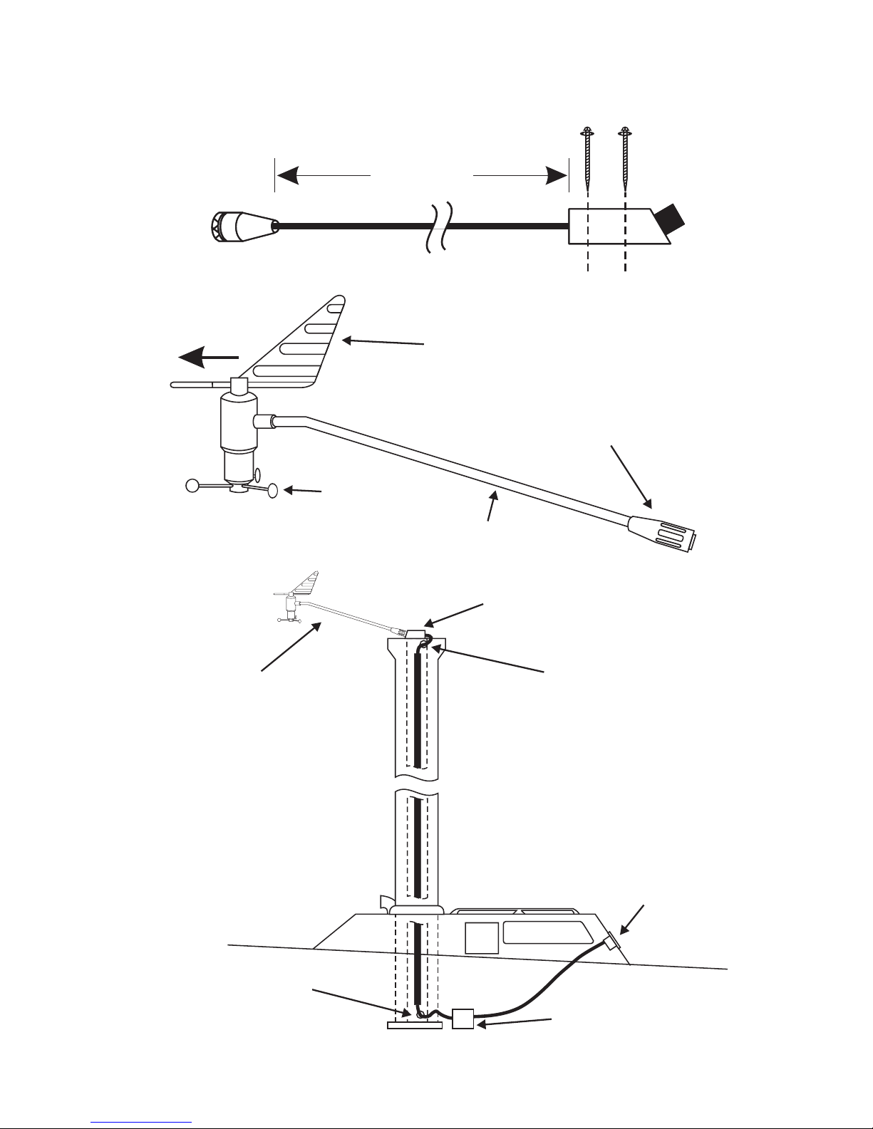
Installation of the NAVMAN W100
Mast Head T ransducer
Electrical connector and threaded
physical support sleeve for
Masthead Assembly
Wind Vane Assembly
Tricup
Assembly
Masthead Boom
FORWARD
100 Feet
(30½ Metres)
Masthead Boom
Pointing Forward
Hole With
Silicone Sealant
NAVMAN W100
Wind Instrument
Junction Box
Cable Mounting
Block
Hole With
Silicone Sealant
Page 10

8 NA VMAN W100 User Manual
Calibration Procedures
Linearisation of the Wind Sensor and
Instrument
Each wind direction sensor has slightly different
electrical characteristics. To provide a highly
accurate display of wind direction data these
characteristics must be entered into the wind
display. This process is called linearisation.
Alignment of the Wind V ane and Display
It is very difficult to align the mast head
transducer in an exact fore and aft position during
installation on the mast. The NAVMAN W100
allows the user to carry out adjustments to the
displayed wind direction after the transducer is
installed.
Wind Speed Calibration
The NAVMAN W100 wind speed transducer is
factory calibrated to read the correct wind speed
under normal conditions. If necessary the user
is able to make adjustments to the wind speed
reading.
Note:
When first installing the NAVMAN W100, the
Linearisation should be performed first,
followed by Alignment then Wind Speed.
Wind Speed
Press and hold the and keys for 3
seconds.
3 SECS
To increase reading press the key.
To decrease reading press the
key.
Each key press results in a 5% change. It may
take 2 or 3 key presses before a change to the
speed can be observed.
To exit press the
key.
Alignment
Whilst in Wind Speed mode, momentarily press
the
and keys.
AP
Press the and keys to change the
displayed wind direction.
To exit press the
key.
Linearisation
Whilst in Alignment mode, press the and
keys until the display shows LE. The display will
flash for 6 seconds before displaying LE.
6 SECS
Rotate the wind vane through two complete
revolutions to allow the NAVMAN W100 to
perform the automatic linearisation process. The
vane can be rotated in either direction.
To exit press the
key.
Note:
If there is any doubt about the accuracy
of the display wind direction, repeat the
linearisation & alignment calibration
procedures.
Page 11

9NA VMAN W100 User Manual
Operation
Backlighting On / Off
Simultaneously press the and keys to
turn the backlight on. Repeat this procedure to
turn the lighting off.
M/S
KTS
VMG
MAX
AP
TR
M/S
KTS
VMG
MAX
AP
TR
Wind Speed Alarm On/Off
Press the key to switch the alarm on and off.
KTS
AP
KTS
AP
Set Wind Speed Alarm
Press and hold the key for 3 seconds.
3 SECS
Use the or keys to set alarm value.
Press the
key to exit.
True or Apparent Wind Display
Press the key to switch between True or
Apparent wind speed.
KTS
AP
KTS
TR
Note:
To obtain true wind data the NAVMAN W100
must be provided with NMEA (VHW) data
from a speed/log instrument, such as the
NAVMAN S100.
Page 12

10 NA VMAN W100 User Manual
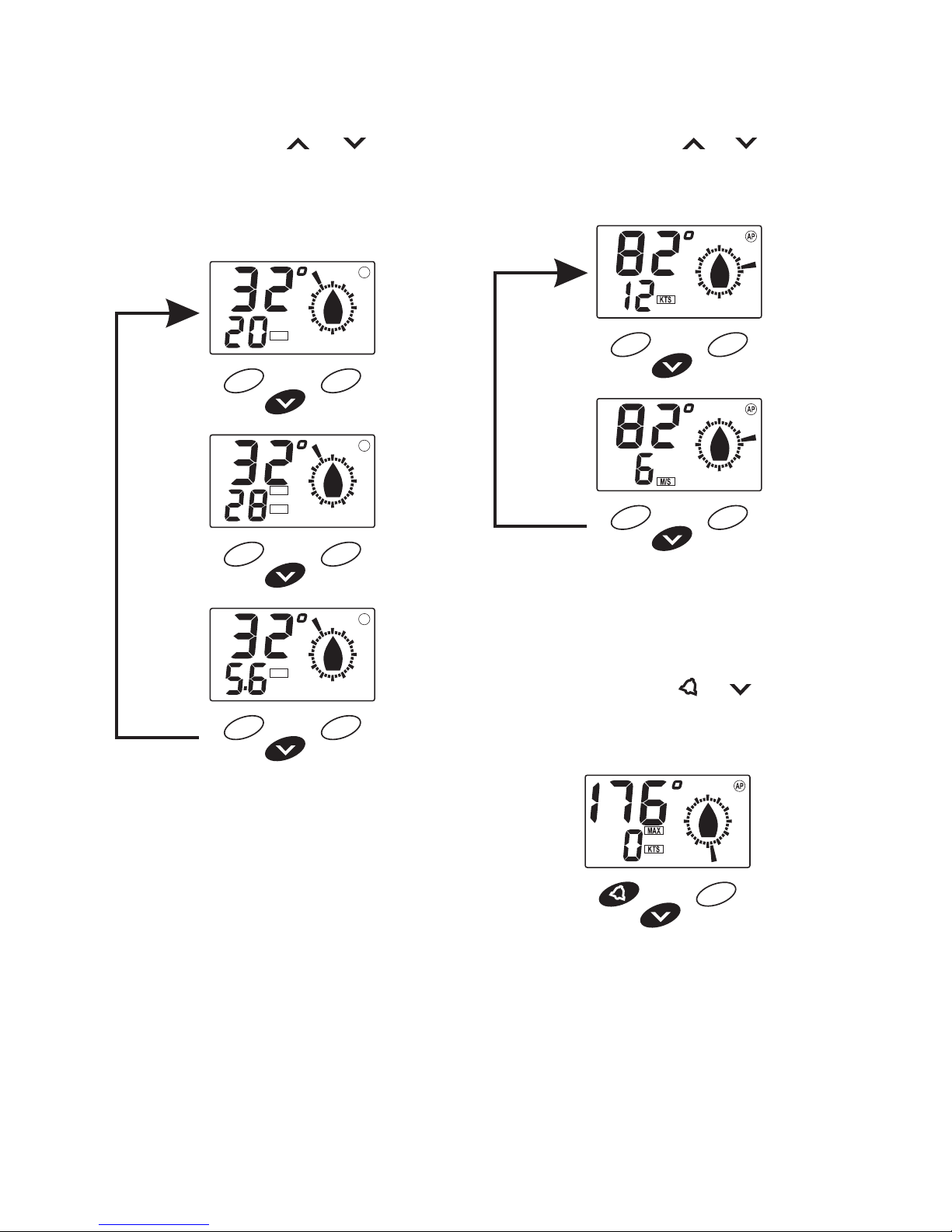
Select Speed Function
Press the key to switch between Wind
Speed, Maximum Wind Speed and VMG.
KTS
KTS
VMG
MAX
AP
AP
AP
Note:
VMG units of measure are the same as the
speed instrument (Knots, MPH, KPH)
providing the boat speed data.
Select Speed Units
Press the or key for 3 seconds to switch
between Knots or Metres/Second.
3 SECS
3 SECS
Reset Maximum Wind Speed
While Maximum Wind Speed is displayed, press
and hold the
and keys for 3 seconds to
reset the maximum wind speed to zero.
3 SECS
Page 13

11NA VMAN W100 User Manual
Troubleshooting Chart
No display:
Check DC power connections and DC polarity with voltmeter. Voltage must
be between 10.7 and 16.6 volts.
Faulty wind speed or wind direction indication:
1. Possible defective Masthead Cable
2. Possible defective Masthead Assembly
3. Possible defective instrument
Remove the Masthead Assembly from the masthead and connect it directly
to the instrument red moulded cable. If the indication is normal, the Masthead
Cable is defective. If the problem persists, contact your supplier for service.
NOTE: The instrument and Masthead Assembly may be connected directly
for linearisation of the repaired or new equipment prior to installation.
No wind speed or wind direction indication
Check the DC power source applied to the NAVMAN W100.
Simulation Mode
At power up, if all the segments display for 5 seconds then the instrument
is in simulation mode.
Page 14

12 NA VMAN W100 User Manual
Page 15

13Girouette anémomètre NAVMAN Manuel d'utilisation
Sommaire
Caractéristiques . . . . . . . . . . . . . . . . . . . . . . . . . . . . . . . . . . . . . . . . . . . . . . . . . . . . . 14
Installation . . . . . . . . . . . . . . . . . . . . . . . . . . . . . . . . . . . . . . . . . . . . . . . . . . . . . . . . . . 15
Emplacement . . . . . . . . . . . . . . . . . . . . . . . . . . . . . . . . . . . . . . . . . . . . . . . . . . . . . 15
Montage . . . . . . . . . . . . . . . . . . . . . . . . . . . . . . . . . . . . . . . . . . . . . . . . . . . . . . . . . 15
Câblage . . . . . . . . . . . . . . . . . . . . . . . . . . . . . . . . . . . . . . . . . . . . . . . . . . . . . . . . . 16
Plusieurs appareils. . . . . . . . . . . . . . . . . . . . . . . . . . . . . . . . . . . . . . . . . . . . . . . . . 16
Installation de l’unité de tête de mât Girouette anémomètre NA VMAN . . . . . . . . . 17
Procédures d’étalonnage . . . . . . . . . . . . . . . . . . . . . . . . . . . . . . . . . . . . . . . . . . . . . . 18
Linéarisation de l’unité de tête de mât et de l’appareil . . . . . . . . . . . . . . . . . . . . . 18
Alignement de l’aérien et de l’affichage . . . . . . . . . . . . . . . . . . . . . . . . . . . . . . . . . 18
Etalonnage de la vitesse du vent . . . . . . . . . . . . . . . . . . . . . . . . . . . . . . . . . . . . . . 18
Vitesse du vent . . . . . . . . . . . . . . . . . . . . . . . . . . . . . . . . . . . . . . . . . . . . . . . . . . . . 18
Alignement . . . . . . . . . . . . . . . . . . . . . . . . . . . . . . . . . . . . . . . . . . . . . . . . . . . . . . . 18
Linéarisation . . . . . . . . . . . . . . . . . . . . . . . . . . . . . . . . . . . . . . . . . . . . . . . . . . . . . . 18
Fonctionnement . . . . . . . . . . . . . . . . . . . . . . . . . . . . . . . . . . . . . . . . . . . . . . . . . . . . . 19
Rétroéclairage . . . . . . . . . . . . . . . . . . . . . . . . . . . . . . . . . . . . . . . . . . . . . . . . . . . . 19
Alarme de vitesse du vent . . . . . . . . . . . . . . . . . . . . . . . . . . . . . . . . . . . . . . . . . . . 19
Réglage du seuil de l’alarme de vent . . . . . . . . . . . . . . . . . . . . . . . . . . . . . . . . . . 19
Sélection vent vrai et apparent. . . . . . . . . . . . . . . . . . . . . . . . . . . . . . . . . . . . . . . . 19
Sélection de la fonction vitesse . . . . . . . . . . . . . . . . . . . . . . . . . . . . . . . . . . . . . . . 20
Sélection des unités de vitesse . . . . . . . . . . . . . . . . . . . . . . . . . . . . . . . . . . . . . . . 20
Mise à zéro de la vitesse maximale . . . . . . . . . . . . . . . . . . . . . . . . . . . . . . . . . . . . 20
En cas de problèmes . . . . . . . . . . . . . . . . . . . . . . . . . . . . . . . . . . . . . . . . . . . . . . . . . 21
W100/FRE/1C
Page 16

14 Girouette anémomètre NA VMAN Manuel d'utilisation
L’affichage est
rétroéclairé pour
la navigation de nuit
Affiche la vitesse
du vent,vitesse
maximale ou VMG
Sélection de l’alarme
de la vitesse maximale
du vent
Sélectionne les fonctions
de l’afficheur inférieur :
vitesse du vent,vitesse maximale ou VMG
Sélectionne la vitesse
et la direction du vent
vrai ou apparent
Indique que la vitesse et
la direction du vent
sont apparents
Indique la direction
(incrémentation de 10 degrés)
Indique que la vitesse
et la direction du vent
sont vraies
Alarme de vitesse du vent
Caractéristiques
• Alimentation
10,7 à 16,6 V c.c., 30 mA nominal, 40mA
avec éclairage
• Température de fonctionnement
0°C à 45°C
• T aille du boîtier
112x112x24mm, profondeur de l’ensemble
35mm.
• T ype d’affichage
Twisted Nematic 0°C à +70°C
• Eclairage
Diode rouge - Marche/ Arrêt par clavier
• Interférences RF
Conformes aux normes CE
• Direction du vent
Vrai et apparent - 180° babord ou tribord.
• Vitesse du vent
0 à 99 noeuds, ou 0 à 50m/sec avec mise
en mémoire de la vitesse max.
• Alarme
Vitesse du vent : réglage propriétaire
• Affichage VMG
Incrémentations de 0,1 jusqu’à 19,9 noeuds
et de 1,0 au-dessus de 20 noeuds
• Entrée NMEA (pour calcul VMG)
Accepte phrases VHW en provenance du
loch série 100 et d’autres instruments ayant
une sortie NMEA
• Sortie NMEA
Format NMEA0183 VWT , VWR, MWV, VPW
pour le répétiteur R100 ou tout autre
appareil compatible NMEA. Protection en
cas de court-circuit. Capacité suffisante
jusqu’à 4 récepteurs NMEA.
• Cables des transducteurs
Connecteur 5 broches Fuji pour l’unité de
tête de mât, câble 5 conducteurs pour
entrée, sortie et alimentation NMEA
• Unité de tête de mât
Matériel léger et résistant livré avec
30mètres de câble. Sortie électronique sine
cosine
Page 17

15Girouette anémomètre NAVMAN Manuel d'utilisation
112mm
(4.4”)
4.5mm
(1.75”)
30mm
(1.2”)
112mm
(4.4”)
24mm
(1”)
56mm
(2.2”)
35mm
(1.4”)
Installation
Emplacement
Le Girouette anémomètre NAVMAN est destiné
à être installé à l’extérieur ou dans la cabine.
Choisissez un emplacement:
à au moins 300mm dun compas
à au moins 500mm dune radio
visible pour lhomme de barre et léquipage
Protégé de tout risque de choc
Accessible pour les branchements
électriques
Montage
La surface de montage doit être plane. Utiliser
l’adhésif de perçage afin de localiser le centre
du trou de montage
Percer un trou de montage dun diamètre de
32mm à travers la cloison
Dévisser lécrou en plastique du boîtier.
Oter la pellicule protectrice du joint
détanchéité. Bien le positionner sur la face
arrière de lappareil, puis le coller.
Insérer les fils et le filetage de lappareil
dans le trou
Bien serrer lécrou sans comprimer le joint
trop fortement, sans quoi létanchéité ne
serait plus garantie.
Page 18

16 Girouette anémomètre NA VMAN Manuel d'utilisation
Vert
Noir
Bleu
Rouge
Données NMEA vers girouette/anémométre
(à partir du Loch)
Unité de tête
de mât
Fusible 1A
+12 V c.c.
Masse
Sortie NMEA vers répétiteur
Prises
Fuji
mâle et
femelle
Vert
Noir
Bleu
Rouge
Noir
Bleu
Rouge
Fusible 1A
+12 V c.c.
Masse
Données NMEA de vitesse
pour le répétiteur
Données NMEA vers
girouette/anémométre
Données NMEA girouette/
anémométre pour le répétiteur
Prises
Fuji
mâle et
femelle
Unité de tête
de mât
Capteur
de vitesse
Plusieurs appareils
L’appareil modèle Girouette
anémomètre NAVMAN peut être
connecté à l’appareil Loch NAVMAN
afin d’afficher la direction et la vitesse
du vent vrai et les données de vitesse
en VMG sur l’écran du Girouette
anémomètre NAVMAN. Le Girouette
anémomètre NAVMAN peut également
être raccordé au répétiteur R100 ou à
tout autre système acceptant le
standard NMEA0183.
Câblage
• Eloigner les cables électriques et ceux de
l’unité de tête de mât d’un alternateur ou de
tout autre câble. Eviter de brancher
l’appareil à des circuits sur lesquels sont
également branchés démarreur,alternateur
ou émetteur radio. Les câbles d’alimentation
électrique doivent être les plus courts
possibles.
• Brancher le fil rouge au pôle positif de
l’alimentation avec un fusible de 1 ampère
ou un disjoncteur. Brancher le fil noir à la
masse. Un fusible de 1 ampère suffira à
protéger 5 appareils.
• Branchez le connecteur 5 broches fuji au
connecteur du cable de l’unité de tête de
mât. NE PAS COUPER LE CABLE DE
L’UNITE DE TETE DE MAT. Des rallonges
sont disponibles chez votre revendeur.
• Si vous n’avez pas d’interface avec un
S100 ou un répétiteur R100, ou si vous ne
pensez pas alimenter un autre appareil en
données NMEA, isoler les fils nus, à
l’extrémité de chacun des câbles inutilisés.
Les entrées et sorties de données NMEA
sont protégées des connections
accidentelles à la masse et au 12V.
Cependant, on ne peut recommander de
laisser l’appareil en mode protection
pendant trop longtemps.
Page 19

17Girouette anémomètre NAVMAN Manuel d'utilisation
Installation de l’unité de
tête de mât Girouette
anémomètre NAVMAN
Connecteur électrique et vis
d'assemblage de l'unité
de tête de mât
Assemblage de la girouette
Montage
des godets
Bras-support
de la girouette
AVANT
100 Pied
(30½ Mètres)
Bras-support de la
girouette pointé vers l'avant
Trou avec
joint silicone
W100
NAVMAN WIND
Boîtier de raccordement
Bloc de montage
des cables
Trou avec
joint silicone
Page 20

18 Girouette anémomètre NA VMAN Manuel d'utilisation
Procédures d’étalonnage
Linéarisation de l’unité de tête de mât
et de l’appareil
Chaque unité a de légères différences au niveau
des caractéristiques électriques. Afin d’obtenir
un affichage le plus précis possible, ses
caractéristiques doivent être entrées dans
l’appareil. On appelle cette procédure
linéarisation.
Alignement de l’aérien et de l’affichage
Il est très difficile de bien aligner l’aérien lors de
l’installation sur le mât. Le Girouette anémomètre
NAVMAN permet à l’utilisateur un mauvais
alignement de la tête de mât.
Etalonnage de la vitesse du vent
L ’unité de mesure de vitesse du vent du Girouette
anémomètre NAVMAN est étalonné à la
fabrication pour afficher la vitesse du vent dans
des conditions normales. En cas de besoins,
l’utilisateur peut effectuer les ajustements
nécessaires à un affichage correct de la vitesse
du vent.
N.B.: Lors de la première installation, il
convient tout d’abord d’effectuer la
linéarisation, puis l’alignement et
enfin, éventuellementl’étalonnage
de la vitesse du vent.
Vitesse du vent
Maintenir les touches et enfoncées
pendant 3 secondes.
3 sec.
Pour augmenter la valeur, appuyer sur la
touche
.
Pour diminuer la valeur, appuyer sur la
touche
.
Chaque pression sur les touches change la
valeur affichée de 5%. Parfois, 2 ou 3 pressions
sont nécessaires avant que la vitesse ne
change.
Pour sortir, appuyer sur la touche
.
Alignement
Lorsque vous êtes en mode vitesse du vent,
appuyer une fois sur les touches
et .
AP
Appuyer sur les touches et pour changer
la direction du vent.
Pour sortir appuyer sur la touche
.
Linéarisation
Lorsque vous êtes en mode Alignement, appuyer
sur les touches
et jusqu’à ce que l’écran
affiche LE. L ’écran clignote pendant 6 secondes
avant d’afficher LE.
6 sec.
Faire faire deux tours complets à la girouette
pour effectuer la linéarisation. Ces deux tours
peuvent être faits dans un sens ou dans l’autre.
Pour sortir, appuyer sur la touche
.
N.B. : Si vous aviez le moindre doute sur
l’exactitude de l’affichage de la direction
du vent, recommencer les procédures de
linéarisation et d’alignement.
Page 21

19Girouette anémomètre NAVMAN Manuel d'utilisation
Fonctionnement
Rétroéclairage
Appuyer simultanément sur les touches et
pour allumer l’écran. Répéter cette
procédure pour l’éteindre.
M/S
KTS
VMG
MAX
AP
TR
M/S
KTS
VMG
MAX
AP
TR
Alarme de vitesse du vent
Appuyer sur la touche pour mettre en marche
ou éteindre l’alarme.
KTS
AP
KTS
AP
Réglage du seuil de l’alarme de vent
Maintenir la touche appuyée pendant 3
secondes.
3 sec.
Utiliser les touches et pour régler la
valeur de l’alarme
Appuyer sur la touche
pour sortir.
Sélection vent vrai et apparent
Appuyer sur la touche pour passer de
l’affichage du vent vrai au vent apparent.
KTS
AP
KTS
TR
N.B.: Afin d’obtenir les données correctes
de vent, le Girouette anémomètre
NAVMAN doit être connecté à un
loch fournissant des données
NMEA (VHW), tel que le Navman Speed.
Page 22
20 Girouette anémomètre NA VMAN Manuel d'utilisation
Sélection des unités de vitesse
Appuyer sur les touches et pendant 3
secondes pour passer des noeuds au m/s.
3 sec.
3 sec.
Mise à zéro de la vitesse maximale
Lorsque la vitesse maximale est affichée,
maintenez les touches
et enfoncées
pendant 3 secondes pour remettre la vitesse
maximale du vent à zéro.
3 sec.
Sélection de la fonction vitesse
Appuyer sur la touche ou pour passer
de la vitesse du vent à la vitesse maximale, à la
VMG.
KTS
KTS
VMG
MAX
AP
AP
AP
N.B. : Les unités de mesure de la VMG sont
identiques à celles du loch (noeuds, mph,
kph) fournissant les informations sur la
vitesse.
Page 23

21Girouette anémomètre NAVMAN Manuel d'utilisation
En cas de problèmes
Pas d’affichage
1. Vérifier les branchements
2. Vérifier les polarités et la tension(10,7 à 16,6V) avec un voltmètre.
Mauvaise indication de la direction ou de la vitesse du vent
1. Défaut dans le câble de l’unité de tête de mât
2. Défaut dans l’assemblage de l’unité de tête de mât
3. Appareil défectueux.
Démontez lunité de tête de mât et branchez-la directement sur le câble
rouge de lappareil. Si les informations sont correctes, le câble est
défectueux. Si le problème persiste, contacter votre revendeur.
N.B. : Il est possible de brancher directement lappareil à lunité de tête
de mât afin deffectuer la linéarisation de lunité neuve ou réparée
avant de linstaller.
Aucune indication de direction ou de vitesse du vent.
Vérifier l’alimentation c.c. du Girouette anémomètre NAVMAN
Mode simulation
Dappareil est en mode simulation lorsque tous les segments de
l’afficheur sont allumés quelques secondes lors de la mise sous tension.
Page 24

22 Girouette anémomètre NA VMAN Manuel d'utilisation
Page 25

23Handbuch NAVMAN W100 W100/GER/1C
Inhalt
Spezifikationen . . . . . . . . . . . . . . . . . . . . . . . . . . . . . . . . . . . . . . . . . . . . . . . . . . . . . . 24
Einbau . . . . . . . . . . . . . . . . . . . . . . . . . . . . . . . . . . . . . . . . . . . . . . . . . . . . . . . . . . . . . 25
Einbau-Ort. . . . . . . . . . . . . . . . . . . . . . . . . . . . . . . . . . . . . . . . . . . . . . . . . . . . . . . . 25
Montage . . . . . . . . . . . . . . . . . . . . . . . . . . . . . . . . . . . . . . . . . . . . . . . . . . . . . . . . . 25
Kabelverbindungen . . . . . . . . . . . . . . . . . . . . . . . . . . . . . . . . . . . . . . . . . . . . . . . . 26
Mehrfach-Instrumentierung . . . . . . . . . . . . . . . . . . . . . . . . . . . . . . . . . . . . . . . . . . 26
NAVMAN W100 - Mastgeber Installation . . . . . . . . . . . . . . . . . . . . . . . . . . . . . . . . . . 27
Kalibrierungen . . . . . . . . . . . . . . . . . . . . . . . . . . . . . . . . . . . . . . . . . . . . . . . . . . . . . . . 28
Kalibrierfunktion aktivieren. . . . . . . . . . . . . . . . . . . . . . . . . . . . . . . . . . . . . . . . . . . 28
Windgeschwindigkeit justieren. . . . . . . . . . . . . . . . . . . . . . . . . . . . . . . . . . . . . . . . 28
Nullausrichtung der Gebereinheit . . . . . . . . . . . . . . . . . . . . . . . . . . . . . . . . . . . . . 28
Linearisierung der Winkelanzeigen . . . . . . . . . . . . . . . . . . . . . . . . . . . . . . . . . . . . 28
Bedienung . . . . . . . . . . . . . . . . . . . . . . . . . . . . . . . . . . . . . . . . . . . . . . . . . . . . . . . . . . 29
Hintergrundbeleuchtung Ein/Aus . . . . . . . . . . . . . . . . . . . . . . . . . . . . . . . . . . . . . . 29
Windstärken-Alarm . . . . . . . . . . . . . . . . . . . . . . . . . . . . . . . . . . . . . . . . . . . . . . . . . 29
Wind-Alarmwert einstellen . . . . . . . . . . . . . . . . . . . . . . . . . . . . . . . . . . . . . . . . . . . 29
Scheinbare oder wahre Windanzeigen . . . . . . . . . . . . . . . . . . . . . . . . . . . . . . . . . 29
Windstärken-Anzeigen . . . . . . . . . . . . . . . . . . . . . . . . . . . . . . . . . . . . . . . . . . . . . . 30
Maßeinheiten wählen . . . . . . . . . . . . . . . . . . . . . . . . . . . . . . . . . . . . . . . . . . . . . . . 30
Maximum-Geschwindigkeit nullsetzen. . . . . . . . . . . . . . . . . . . . . . . . . . . . . . . . . . 30
Fehler-Suchliste . . . . . . . . . . . . . . . . . . . . . . . . . . . . . . . . . . . . . . . . . . . . . . . . . . . . . 31
Page 26

24 Handbuch NA VMAN W100
Die Anzeige ist
hintergrundbeleuchtet
Anzeige - Windstärke,
Maximum-Wind
oder Gutgemachte
Fahrt (VMG)
Maximum-Wind
Ein/Aus
Durchwahl der unteren
Zeile: Windstärke,
Max. Wind und VMG
Wahl zwischen wahren und
scheinbaren Winddaten
Anzeige scheinbare
Winddaten
Winkelrichtung in
10°-Schritten
Anzeige wahre
Winddaten
Windgeschwindigk. Alarm
Spezifikationen
• Spannungsversorgung
10,7 bis 16,6 VDC, 30mA nominal, 40mA
mit Hintergrundbeleuchtung.
• Betriebstemperatur
0°C bis 45°C.
• Instrumentenmaße
112 x 112 x 20mm (4,4 x 4,4 x 1")
Einbautiefe 35mm (in der Montagefläche).
• Display-Art
TN-LCD, mit grauem Hintergrund 0°C bis
+70°C.
• Beleuchtung
Schaltbare rote LED.
• RF Störungen
Weniger als 6dB (entsprechend den
europäischen EC-Spezifikationen).
• Windrichtung
Scheinbare und wahre Richtung, 180° nach
BB und nach StB.
• Windgeschwindigkeit
0 bis 99kn oder 0 bis 50m/sec mit
Speicherung der Maximalgeschwindigkeit.
• Alarm
Windgeschwindigkeit mit wählbarem
Grenzwert.
• Gutgemachte Geschwindigkeit - VMG
Anzeige in 0,1Schritten bis 19,9kn und in
1,0 Schritten über 20kn.
• NMEA-Eingang (für VMG Kalkulation)
Übernimmt VHW-Sequenzen vom NAVMAN
S100-Log oder entspr. Instrumenten mit
NMEA-Ausgang.
• NMEA-Ausgang
NMEA0183-Sequenzen, - VWT, VWR, MWV,
VPW zum NAVMAN R100 Instrument oder
anderen Instrumenten mit entspr. NMEAEingängen. Bis zu 4 Instrumente
anschließbar. Der Ausgang ist
kurzschlußsicher.
• Masteinheit
Robuste, wetterfeste Einheit in
Leichtbauweise mit 30m Kabel.
Elektronischer Sinus/Cosinus-Ausgang.
• Instrumenten-Anschluß
5-Pin Fujistecker für das Geberkabel und 5Ader Kabelanschluß für NMEA Ein- und
Ausgang sowie Netzanschluß.
Page 27

25Handbuch NAVMAN W100
112mm
(4.4”)
4.5mm
(1.75”)
30mm
(1.2”)
112mm
(4.4”)
24mm
(1”)
56mm
(2.2”)
35mm
(1.4”)
Einbau
Einbau-Ort
Das NAVMAN W100 ist für Innen- wie auch für
Außenmontage geeignet. Folgendes muß für
den Einbauort sichergestellt sein:
• Mindestabstand zum Kompaß – 300mm
• Mindestabstand zu einem Radio – 500mm
• Gute Ablesbarkeit vom Steuerstand aus
• Schutz vor Beschädigungen
• Möglichkeit der Kabelzuführung
• Zugang von der Einbauort-Rückseite
Montage
Die Montagefläche muß einwandfrei eben sein.
Mit der Schablone die Bohrungsmitte festlegen.
• Eine kreisförmige Öffnung mit einem.
Durchmesser von32mm bohren.
• Die Befestigungsmutter abnehmen.
• Die Schutzhaut von der Dichtung entfernen
und die Dichtung auf die Geräterückseite
kleben.
• Das Gerät einsetzen, die Mutter von hinten
aufschrauben. Mit einem Schlüssel leicht
anziehen. Die Dichtung darf nicht zu stark
gequetscht werden.
Page 28

26 Handbuch NA VMAN W100
Grün
Schwarz
Blau
Rot
NMEA-Eingangsdaten vom Log
Wind-Geber
1A Sicherung
+12 VDC
Masse
NMEA-Ausgangsdaten
zu Instrumenten
Fuji
Stecker
+ Kupplg
Grün
Schwarz
Blau
Rot
Schwarz
Blau
Rot
1A Sicherung
+12 VDC
Masse
NMEA-Fahrtdaten zu Anzeigen
NMEA-Daten zum Wind
NMEA-Winddaten zu Anzeigen
Wind-Geber
Log-Geber
Fuji
Stecker
+ Kupplg
Kabelverbindungen
• Die Verbindungskabel nicht parallel mit
anderen Bordkabeln verlegen. Die
Spannung nicht parallel von
Versorgungsanschlüssen für Generatoren,
Umformern und Funksendern abnehmen.
Getrennte Zuleitung vom Hauptverteiler
oder von der Batterie verwenden.
MehrfachInstrumentierung
Das NAVMAN W100 läßt sich al
s separates Instrument wie auch
parallel zu anderen Instrumenten
der 100er Serie, sowie auch zu
Fremdfabrikaten verwenden,
wenn entspr. NMEA0183-Daten
akzeptiert werden.
• Die rote Ader über eine Sicherung von
1Amp an die Plus-Spannung anschließen.
1Amp reicht als Schutz für bis zu 5
Instrumente der Serie 100. Die schwarze
Ader an die Minus-Spannung, bzw. an
Masse anschließen.
• Das Windgeberkabel mit dem 4-poligen
Fujistecker verbinden. Ist das Geberkabel
zu kurz, kann ein Verlängerungskabel
geliefert werden. Ein zu langes Kabel sollte
nicht gekürzt werden.
• Sollen keine Verbindungen zu anderen
System-Instrumenten hergestellt werden
und werden keine NMEA-Daten von und zu
anderen Instrumenten benötigt, die nicht
benötigten Adern kürzen und isolieren.
Page 29
27Handbuch NAVMAN W100
NAVMAN W100 - Mastgeber
Installation
Schraub0Befestigung
und Stecker-Verbindung
Windfahne
Dreifach
Wind-Impeller
Tragerohr
VORAUS
30,5m
in Schiffsvorausrichtung
installieren
Kabelführung
NAVMAN W100
Instrument
Anschluß-Box
Geber-
montagefuß
Kabelführung
Page 30

28 Handbuch NA VMAN W100
Nullausrichtung der Gebereinheit
Nach Aktivierung der Kalibrierfunktion, die
Tasten
und erneut kurz drücken. Die
“CA”-Anzeige erscheint in der unteren Zeile.
Darüber wird der Windwinkel gezeigt.
AP
Nun mit den Pfeiltasten den Winkelwert
berichtigen, bis die Anzeige mit dem Winkelwert
der Windfahne am Geber übereinstimmt.
Linearisierung der Winkelanzeigen
Es besteht die Möglichkeit, daß die Umrechnung
der mechanischen Windwinkelstellung nicht für
jeden Kreisbereich linear erfolgt. Zur
entsprechenden Kalibrierung die
Kalibrierfunktion aktivieren, dann die Tasten
und erneut kurz drücken und danach 6
Sekunden lang gedrückt halten. Die Anzeige
blinkt in dieser Zeit und zeigt dann “LE” an.
6 Sekunden
Nun muß die Windfahne zweimal vollständig
gedreht werden. Das muß langsam und sehr
gleichmäßig erfolgen. Der Mikroprozessor erfaßt
ungleichmäßig sich ändernde Winkelwerte und
linearisiert diese.
Zum Abschluß die Taste
drücken.
Kalibrierungen
Für die NAVMAN W100-Anlage sind folgende
drei Kalibrierungen möglich:
• Nullausrichtung der Gebereinheit
• Linearisierung der Winkelanzeigen
• Korrektur der Geschwindigkeitsanzeige
HINWEIS:
Nach Installation sollte zuerst die
Linearisierung erfolgen, dann die
Nullausrichtung des Gebers und zum Schluß
die Geschwindigkeitskorrektur.
Kalibrierfunktion aktivieren
Die T asten und für 3 Sekunden gedrückt
halten.
Es erscheinen oben die Zeichen “CA” und unten
der Geschwindigkeitswert.
3 Sekunden
Windgeschwindigkeit justieren
Ist die “CA”-Anzeige aktiv , mit der Taste den
Wert nach oben und mit der Taste den Wert
nach unten berichtigen. Jedes Drücken
verändert den Wert um 5%. Es dauert 2 bis 3
Sekunden, bis die Anzeige entsprechend
berichtigt wird.
HINWEIS:
Die Kalibrierfunktion kann jederzeit durch
Drücken der Taste
verlassen werden.
Page 31

29Handbuch NAVMAN W100
Wind-Alarmwert einstellen
Um einen Grenzwert einzustellen, bei dem der
Alarm ausgelöst werden soll, die Taste
3
Sekunden gedrückt halten, bis “AL” erscheint.
3 Sekunden
Mit den Tasten bzw. den Alarmwert
einstellen.
Zum Schluß die Taste
drücken.
Scheinbare oder wahre Windanzeigen
Mit der Taste zwischen den beiden
Möglichkeiten wechseln.
KTS
AP
KTS
TR
HINWEIS:
Um wahre Windanzeigen zu erhalten, müssen
von einem Log über den NMEA0183 Anschluß
die VHW Sequenzen empfangen werden.
Bedienung
Hintergrundbeleuchtung Ein/Aus
Zum Einschalten, die Tasten und
gleichzeitig drücken. Zum Ausschalten den
Vorgang wiederholen.
M/S
KTS
VMG
MAX
AP
TR
M/S
KTS
VMG
MAX
AP
TR
Windstärken-Alarm
Die Aktivierung wie auch die Deaktivierung
erfolgen durch Drücken der Taste
.
KTS
AP
KTS
AP
Page 32

30 Handbuch NA VMAN W100
Maßeinheiten wählen
Die Taste oder drei Sekunden lang
gedrückt halten.
Damit wechselt die Anzeige zwischen Knoten
und Meter pro Sekunde.
3 Sekunden
3 Sekunden
Maximum-Geschwindigkeit nullsetzen
Um einen neuen Maximal-Windwert zu erhalten,
muß der alte Wert auf Null gesetzt werden.
Hierzu die “MAX”-Anzeige aktivieren und dann
die T asten
und 3 Sekunden lang gedrückt
halten, bis “0” gezeigt wird.
3 Sekunden
Windstärken-Anzeigen
Mit der Taste können folgende Werte
aufgerufen werden:
die aktuelle Geschwindigkeit,
der maximale gemessene Wert (MAX)
die gutgemachte Geschwindigkeit (VMG)
KTS
KTS
VMG
MAX
AP
AP
AP
HINWEIS:
Die Maßeinheit für VMG entspricht der Einheit,
die am Log aktiviert ist, von dem die
Fahrtdaten übertragen werden. (Knoten, MPH
oder KPH)
Page 33

31Handbuch NAVMAN W100
Fehler-Suchliste
Keine Anzeige:
1. Spannungsversorgung auf korrekten Wert und richtige Polarität prüfen.
2. Die Spannung muß zwischen 10,7 und 16,6 Volt liegen.
Keine Windanzeigen:
Spannungsversorgung zum Windgeber überprüfen.
Fehlerhafte Windanzeigen:
1. Möglicher Defekt im Verbindungskabel
2. Möglicher Defekt in der Mastkopfeinheit
3. Möglicher Defekt im Instrument
Die Windgebereinheit abnehmen und direkt am Instrumentenstecker
ansetzen. Sind nun normale Anzeigen vorhanden, liegt der Defekt in der
Kabelverbindung nach oben
Verbleiben fehlerhafte Anzeigen, mit einem technischen Service Kontakt
aufnehmen.
Hinweis: Ist nach Installation oder nach Reparatur eine Linearisierung
erforderlich, kann die Windgebereinheit bevorzugt direkt an das
Instrument angeschlossen werden.
Page 34

32 Handbuch NA VMAN W100
Page 35

33NA VMAN W100 Gebruikers Handleiding
Inhoud
Specificaties . . . . . . . . . . . . . . . . . . . . . . . . . . . . . . . . . . . . . . . . . . . . . . . . . . . . . . . . 34
Installatie . . . . . . . . . . . . . . . . . . . . . . . . . . . . . . . . . . . . . . . . . . . . . . . . . . . . . . . . . . . 3 5
Plaats . . . . . . . . . . . . . . . . . . . . . . . . . . . . . . . . . . . . . . . . . . . . . . . . . . . . . . . . . . . 35
Montage . . . . . . . . . . . . . . . . . . . . . . . . . . . . . . . . . . . . . . . . . . . . . . . . . . . . . . . . . 35
Bedrading . . . . . . . . . . . . . . . . . . . . . . . . . . . . . . . . . . . . . . . . . . . . . . . . . . . . . . . . 36
Diverse instrumenten . . . . . . . . . . . . . . . . . . . . . . . . . . . . . . . . . . . . . . . . . . . . . . . 36
Installatie van de NAVMAN W100 Masttop-unit . . . . . . . . . . . . . . . . . . . . . . . . . . . . 37
Calibratieprocedures . . . . . . . . . . . . . . . . . . . . . . . . . . . . . . . . . . . . . . . . . . . . . . . . . 38
Afregelen van de windsensor en het instrument . . . . . . . . . . . . . . . . . . . . . . . . . . 38
Uitlijnen van windvaan en display . . . . . . . . . . . . . . . . . . . . . . . . . . . . . . . . . . . . . 38
Calibratie windsnelheid . . . . . . . . . . . . . . . . . . . . . . . . . . . . . . . . . . . . . . . . . . . . . 38
Windsnelheid . . . . . . . . . . . . . . . . . . . . . . . . . . . . . . . . . . . . . . . . . . . . . . . . . . . . . 38
Uitlijnen. . . . . . . . . . . . . . . . . . . . . . . . . . . . . . . . . . . . . . . . . . . . . . . . . . . . . . . . . . 38
Afregelen. . . . . . . . . . . . . . . . . . . . . . . . . . . . . . . . . . . . . . . . . . . . . . . . . . . . . . . . . 38
Bediening . . . . . . . . . . . . . . . . . . . . . . . . . . . . . . . . . . . . . . . . . . . . . . . . . . . . . . . . . . . 39
Achtergrondverlichting aan/uit . . . . . . . . . . . . . . . . . . . . . . . . . . . . . . . . . . . . . . . . 39
Alarm windsnelheid aan/uit . . . . . . . . . . . . . . . . . . . . . . . . . . . . . . . . . . . . . . . . . . 39
Alarm windsnelheid instellen . . . . . . . . . . . . . . . . . . . . . . . . . . . . . . . . . . . . . . . . . 39
Afbeelden schijnbare of ware wind . . . . . . . . . . . . . . . . . . . . . . . . . . . . . . . . . . . . 39
Kiezen snelheidsfuncties . . . . . . . . . . . . . . . . . . . . . . . . . . . . . . . . . . . . . . . . . . . . 40
Kiezen eenheid voor snelheid . . . . . . . . . . . . . . . . . . . . . . . . . . . . . . . . . . . . . . . . 40
Nulstellen maximale snelheid . . . . . . . . . . . . . . . . . . . . . . . . . . . . . . . . . . . . . . . . 40
Problemen oplossen . . . . . . . . . . . . . . . . . . . . . . . . . . . . . . . . . . . . . . . . . . . . . . . . . . 41
W100/DUT/1C
Page 36

34 NA VMAN W100 Gebruikers Handleiding
Specificaties
• Voeding
10,7 tot 16,6 VDC, 30mA nominaal, 40mA
met achtergrondverlichting aan.
• Bedrijfstemperatuur
0°C tot 45°C.
• Afmetingen display
112 x 112 x 24 mm, totale diepte 35 mm
achter paneel.
• Soort display
Twisted Nematic-cel, grijze achtergrond
0°C tot +70°C.
• Verlichting
Rode LED inschakelbaar vanaf toetsenblok.
• HF-storing
Minder dan 6 dB maximale ruis op elk
maritiem radiokanaal met een 3 dB
versterkte antenne binnen 1 meter van de
bovenkant van het display (Europese ECspecificaties).
• Windrichting
Schijnbare en ware richting 180 graden
bakboord en stuurboord.
• Windsnelheid
0 tot 99 knopen, of 0 tot 50 m/sec met
geheugen voor maximale windsnelheid.
• Alarm
Alarm windsnelheid, instelbaar door de
gebruiker.
• VMG
Afgebeeld in stappen van 0,1 tot 19,9
knopen en van 1,0 vanaf 20 knopen.
• NMEA-ingang (voor berekening ware
bootsnelheid)
Accepteert VHW -zin van NAVMAN S100
log/snelheidsmeter of ander instrument met
NMEA-uitgang.
• NMEA-uitgang
NMEA 0183-formaat VWT, VWR, MWV,
VPW voor NAVMAN R100
systeemversterker of ander NMEAcompatibel instrument. Beschermd tegen
kortsluiting. Geschikt voor aansturing van
maximaal vier NMEA-ontvangers.
• Sensorkabels
5-pins Fuji-stekker voor masttopwindsensor, 5-aderige kabel voor NMEAingang en -uitgang en voeding.
• Sensor
Lichtgewicht weerbestendig type met 30
meter kabel. Elektronische sinus/cosinusuitgang
Display met
achtergrondverlichting
voor gebruik bij nacht
Aflezing windsnelheid,
maximale windsnelheid,
of VMG
Maximale
windsnelheid aan/uit
Selecteren functie op
onderste deel display,
windsnelheid, max.
windsnelheid of VMG
Selecteren ware of schijnbare
windsnelheid en richting
Geeft aan snelheid en
richting schijnbare wind
Geeft aan richting in
stappen van 10 graden
Geeft aan richting en
snelheid ware wind
Alarm windsnelheid
Page 37

35NA VMAN W100 Gebruikers Handleiding
112mm
(4.4”)
4.5mm
(1.75”)
30mm
(1.2”)
112mm
(4.4”)
24mm
(1”)
56mm
(2.2”)
35mm
(1.4”)
Installatie
Plaats
De NAVMAN W100 is geschikt voor installatie
binnen of buiten. Kies een plaats die voldoet aan
het volgende:
• Tenminste 300 mm van een kompas.
• Tenminste 500 mm van een radio.
• Makkelijk af te lezen door roerganger en
bemanning.
• Veilig voor mechanische beschadiging.
• Bereikbaar met elektriciteitskabels.
Montage
Het montageoppervlak moet vlak zijn. Gebruik
de mal om het midden van het montagegat af te
tekenen.
• Boor een montagegat rond 32 mm door het
schot.
• Verwijder de bevestigingsmoer. Trek het
beschermende papier van de schuimstof
pakking af en bevestig de pakking aan de
achterkant van het instrument.
• Steek het instrument door het luik.
Zet de moer handvast en draai hem aan
met een tang. Draai de moer niet zo vast
dat de ring zijn waterdichte werking verliest.
Page 38

36 NA VMAN W100 Gebruikers Handleiding
Groen
Zwart
Blauw
Rood
Zwart
Blauw
Rood
Aarde
NMEA-snelheidsgegevens naar
repeater
NMEA-gegevens
naar wind
NMEA wind data naar repeater
Windsensor
Snelheidsensor
Fuji
stekker en
contrastekker
1A zekering
+12 V
gelijkspanning
Diverse instrumenten
De windmeter NAVMAN W100 kan
worden aangesloten op de NAVMAN
S100 snelheidsmeter, zodat op het
display van de NAVMAN W100 de
ware windsnelheid en windrichting en
de VMG afgebeeld kunnen worden.
De NAVMAN W100 kan ook
aangesloten worden op de NAVMAN
R100 systeemrepeater of op andere
instrumenten die gegevens volgens
NMEA 0183 kunnen verwerken.
Groen
Zwart
Blauw
Rood
NMEA-gegevens naar wind (van snelheid/log)
Windsensor
Aarde
Fuji
stekker en
contrastekker
1A zekering
+12 V
gelijkspanning
NMEA-uitgang naar repeater
Bedrading
• Houd elektrische en sensorkabels
verwijderd van de dynamo of andere kabels
die elektrische storing veroorzaken. Sluit
het instrument bij voorkeur niet aan op
groepen waarop ook de ontsteking,
dynamo’ s, omzetters, en radiozenders zijn
aangesloten. Verbindingen met
stroombronnen moeten altijd zo kort
mogelijk gehouden worden.
• Verbind de rode draad
met de plus van de
voeding via een
zekering of onderbreker
van 1 Amp. Verbind de
zwarte draad met de
aarde. Een zekering van
1 Amp biedt
bescherming voor
maximaal vijf
instrumenten
van de 100
serie.
• Sluit de 5-pins Fuji-stekker aan op de
windsensorkabel. De sensorkabel mag niet
worden geknipt of ingekort. Er zijn
verlengkabels verkrijgbaar voor het geval
de sensorkabel te kort is.
• Als u geen NAVMAN S100 snelheidsmeter
aansluit, geen NAVMAN R100 repeater
gebruikt of u bent niet van plan NMEAgegevens naar een ander instrument te
sturen, isoleer dan het blanke uiteinde van
de blauwe draad. De NMEAgegevensingang en -uitgang zijn
beschermd tegen onbedoelde aansluiting
aan de aarde en aan 12 Volt, maar het is
niet aan te raden het instrument gedurende
langere tijd van die bescherming gebruik te
laten maken.
Page 39

37NA VMAN W100 Gebruikers Handleiding
Installatie van de NA VMAN W100 Masttop-unit
Electrische aansluiting en
steunbus met schroefdraad
voor masttopunit
Windvaan
Tricup
Masttopunit
VOORUIT
100 Fot
(30½ Meter)
Masttopunit
vooruit
Gat met
siliconenkit
NAVMAN W100
Windmeter
Aansluitdoos
Montageblok
kabel
Gat met
siliconenkit
Page 40

38 NA VMAN W100 Gebruikers Handleiding
Calibratieprocedures
Afregelen van de windsensor en het
instrument
Elke windrichtingsensor heeft een iets andere
elektrische karakteristiek. Om de gegevens over
de windrichting zo nauwkeurig mogelijk af te
beelden, moet deze karakteristiek ingevoerd
worden op het display.
Uitlijnen van windvaan en display
Het is erg moeilijk om de masttopsensor
nauwkeurig in de juiste positie in de lengterichting
te zetten bij installatie op de mast. Met de
NA VMAN W100 kan de gebruiker de afgebeelde
windrichting bijstellen nadat de sensor is
geplaatst.
Calibratie windsnelheid
De windsnelheidsensor van de NA VMAN W100
is in de fabriek gecalibreerd, zodat hij onder
normale omstandigheden de juiste windsnelheid
aangeeft. Zonodig kan de gebruiker de aflezing
van de windsnelheid bijstellen.
NB: Als de NAVMAN W100 nieuw wordt
geïnstalleerd, moet eerst het afregelen
worden uitgevoerd, gevolgd door het uitlijnen
en dan het calibreren van de windsnelheid.
Windsnelheid
Druk de toetsen en in en houd ze drie
seconden vast.
3 sec
Druk op de toets om de waarde ter verhogen.
Druk op de toets
om de waarde te verlagen.
Elke keer als u op een toets drukt verandert de
waarde met 5%. Het kan zijn dat u 2 of 3 keer
moet drukken voordat u de snelheid ziet
veranderen.
Druk op de toets
om te eindigen.
Uitlijnen
Druk in windsnelheidmodus kort op de toetsen
en .
AP
Druk op de toetsen en om de windrichting
op het display te veranderen.
Druk op de toets
om te eindigen.
Afregelen
Druk in afregelmodus de toetsen en in
totdat op het display de letters LE verschijnen.
Het display knippert eerst 6 seconden voordat
de letters LE verschijnen.
6 sec
Draai de windvaan twee keer helemaal rond
zodat de NAVMAN W100 het afregelen
automatisch kan uitvoeren. De vaan kan in beide
richtingen gedraaid worden.
Druk op de toets
om te eindigen.
NB: Als u twijfelt aan de juistheid van de
windrichting op het display, herhaal dan de
calibratieprocedures voor het afregelen en
uitlijnen.
Page 41

39NA VMAN W100 Gebruikers Handleiding
Bediening
Achtergrondverlichting aan/uit
Druk tegelijk op de toetsen en om de
achtergrondverlichting in te schakelen. Herhaal
dit om de verlichting weer uit te doen.
M/S
KTS
VMG
MAX
AP
TR
M/S
KTS
VMG
MAX
AP
TR
Alarm windsnelheid aan/uit
Druk op de toets om het alarm aan of uit te
zetten.
KTS
AP
KTS
AP
Alarm windsnelheid instellen
Druk op de toets en houd deze 3 seconden
ingedrukt
3 sec
Druk op de toetsen of om de
alarmwaarde in te stellen
Druk op de toets
om te eindigen.
Afbeelden schijnbare of ware wind
Druk op de toets om te wisselen tussen
ware of schijnbare windrichting.
KTS
AP
KTS
TR
NB: Om de ware windgegevens te kunnen
bepalen, moet de NAVMAN W100 voorzien
worden
van gegevens volgens NMEA (VHW) door
een log/snelheidsmeter, bijvoorbeeld de
Navman log-snelheidsmeter.
Page 42

40 NA VMAN W100 Gebruikers Handleiding
Kiezen snelheidsfuncties
Druk op de toets om te wisselen tussen
windsnelheid, maximale windsnelheid en VMG.
KTS
KTS
VMG
MAX
AP
AP
AP
NB: De eenheid voor de VMG is gelijk aan die
van de snelheidsmeter die de gegevens over
de bootsnelheid levert (Knopen, MPH, km/h)
Kiezen eenheid voor snelheid
Druk de toetsen of 3 seconden in om te
wisselen tussen knopen of meter/seconde.
3 sec
3 sec
Nulstellen maximale snelheid
Zorg dat de maximale windsnelheid op het
display staat, druk op de toetsen
en en
houd ze 3 seconden vast om de maximale
windsnelheid op nul te zetten.
3 sec
Page 43

41NA VMAN W100 Gebruikers Handleiding
Problemen oplossen
Niets op display:
Controleer de aansluiting van de voeding en de polariteit van de
gelijkspanning met een voltmeter. De spanning moet tussen 10,7 en 16,6
volt liggen.
Verkeerde aflezing van windsnelheid of windrichting
1. Mogelijk defecte kabel naar masttop.
2. Mogelijk defecte masttopunit.
3. Mogelijk defect instrument.
Verwijder de masttopunit van de masttop en sluit deze rechtstreeks aan op
de rode kabel van het instrument. Als de aflezing normaal is, dan is de
kabel naar de masttop defect. Als het probleem blijft bestaan, neem dan
contact op met uw leverancier.
NB: Het instrument en de masttopunit kunnen rechtstreeks met elkaar
verbonden worden voor het afregelen van gerepareerde of nieuwe
apparaten voorafgaand aan installatie.
Geen aflezing van windsnelheid of windrichting
Controleer de elektrische voeding van de NAVMAN W100.
Page 44

42 NA VMAN W100 Gebruikers Handleiding
Page 45

43NAVMAN W100 Handbok
Innehåll
Specifikationer . . . . . . . . . . . . . . . . . . . . . . . . . . . . . . . . . . . . . . . . . . . . . . . . . . . . . . 44
Installation . . . . . . . . . . . . . . . . . . . . . . . . . . . . . . . . . . . . . . . . . . . . . . . . . . . . . . . . . . 45
Lokalisering . . . . . . . . . . . . . . . . . . . . . . . . . . . . . . . . . . . . . . . . . . . . . . . . . . . . . . 45
Montering . . . . . . . . . . . . . . . . . . . . . . . . . . . . . . . . . . . . . . . . . . . . . . . . . . . . . . . . 45
Kabeldragning . . . . . . . . . . . . . . . . . . . . . . . . . . . . . . . . . . . . . . . . . . . . . . . . . . . . 46
Flera instrument . . . . . . . . . . . . . . . . . . . . . . . . . . . . . . . . . . . . . . . . . . . . . . . . . . . 46
Installation av NAVMAN W100 mastenhet . . . . . . . . . . . . . . . . . . . . . . . . . . . . . . . . 47
Inställning av givare . . . . . . . . . . . . . . . . . . . . . . . . . . . . . . . . . . . . . . . . . . . . . . . . . . 48
Inriktning av mastenhet. . . . . . . . . . . . . . . . . . . . . . . . . . . . . . . . . . . . . . . . . . . . . . 48
Vindhastighets kalibrering . . . . . . . . . . . . . . . . . . . . . . . . . . . . . . . . . . . . . . . . . . . 48
Vindhastighet . . . . . . . . . . . . . . . . . . . . . . . . . . . . . . . . . . . . . . . . . . . . . . . . . . . . . 48
Inriktning . . . . . . . . . . . . . . . . . . . . . . . . . . . . . . . . . . . . . . . . . . . . . . . . . . . . . . . . . 48
Inställning . . . . . . . . . . . . . . . . . . . . . . . . . . . . . . . . . . . . . . . . . . . . . . . . . . . . . . . . 48
Handhavande . . . . . . . . . . . . . . . . . . . . . . . . . . . . . . . . . . . . . . . . . . . . . . . . . . . . . . . 49
Belysning av/på . . . . . . . . . . . . . . . . . . . . . . . . . . . . . . . . . . . . . . . . . . . . . . . . . . . 49
Vindalarm av/på . . . . . . . . . . . . . . . . . . . . . . . . . . . . . . . . . . . . . . . . . . . . . . . . . . . 49
Inställning av vindalarm . . . . . . . . . . . . . . . . . . . . . . . . . . . . . . . . . . . . . . . . . . . . . 49
Sann eller skenbar vindhastighet. . . . . . . . . . . . . . . . . . . . . . . . . . . . . . . . . . . . . . 49
Val av fart funktion. . . . . . . . . . . . . . . . . . . . . . . . . . . . . . . . . . . . . . . . . . . . . . . . . . 50
Val av enheter . . . . . . . . . . . . . . . . . . . . . . . . . . . . . . . . . . . . . . . . . . . . . . . . . . . . . 50
Nollställning av max.vindhastighet. . . . . . . . . . . . . . . . . . . . . . . . . . . . . . . . . . . . . 50
Felsökning . . . . . . . . . . . . . . . . . . . . . . . . . . . . . . . . . . . . . . . . . . . . . . . . . . . . . . . . . . 51
W100/SWE/1C
Page 46
44 NAVMAN W100 Handbok
Bakgrundsbelysning
Visar vindhastighet,
VMG eller max.
vindhastighet
Max. vindhastighet
av/på
Val av undre radens
funktion Vindhastighet,
max. vindhastighet
eller VMG.
Val av sann eller skenbar
vindhastighet och riktning
Indikerar skenbar
vindriktning
Indikerar riktning i 10
graders intervaller
Indikerar sann vind
hastighet/riktning
Vindalarm
Specifikationer
• Strömförsörjning
10,7 till 16,6volt 30 mA normalt 40 mA med
belysning.
• Temperaturområde
0 C till 45 C.
• Storlek på display
112 x 112 x 24 mm, 35mm djup.
• Displaytyp
Twistad Nematic grå bakgrund 0 C – +70 C
• Belysning
Röd LED belysning.
• Radioavstörning
Mindre än 6db maximal dämpning på alla
radiokanaler vid 3dB gain från instrument
(EU specifikation) när antenn befinner sig
inom 1 m.
• Vindriktning
Sann och skenbar 180 grader SB eller BB.
• Vindhastghet
0-50 m/ eller 50 knop.
• Alarm
Inställbart vindhastighetsalarm.
• VMG display
Visar med en decimal och hela knop över
20 knop.
• NMEA ingång (för VMG)
NMEA 0183 VHW från S 100 logg eller
annan logg med NMEA.
• NMEA Utgång
NMEA 0183 sänder VWT, VWR, MWV, VPW,
till R 100 eller annan repeater med NMEA.
Kan kopplas upp till 4 repeatrar.
• Givarkablar
5 poliga FUJI kontakter för vindgivare.
• Mastenhet
Lättvikts stryktålig modell med 30m kabel.
Utgång SIN/COS
Page 47

45NAVMAN W100 Handbok
112mm
(4.4”)
4.5mm
(1.75”)
30mm
(1.2”)
112mm
(4.4”)
24mm
(1”)
56mm
(2.2”)
35mm
(1.4”)
Installation
Lokalisering
NAVMAN W100 är designad för att monteras
över eller under däck. Välj ett ställe som är:
minst 300mm från närmaste kompass
minst 500mm från närmaste radio
lättavläst för rorsman
åtkomligt för kablar
Montering
Monteringsytan måste vara jämn. Använd
borrmallen för att centrera genomföringen.
borra ett 32mm hål i skottet
ta bort muttern. Limma fast packningen på
instrumentets baksida
sätt i instrumentet i det borrade hålet
Handdra endast muttern. Drag inte för hårt
då packning ej blir vattentät om den trycks
ihop för mycket.
Page 48

46 NAVMAN W100 Handbok
Grön
Svart
Blå
Röd
NMEA data till vind (från fart/tripp)
Vindgivare
1A Säkring
+12v dc
Jord
NMEA utgång till repeater
Fuji on-
och han
kontakt
Grön
Svart
Blå
Röd
Svart
Blå
Röd
1A Säkring
+12v dc
Jord
NMEA fart data till repeater
NMEA data till vind
NMEA vind data till repeater
Fuji onoch han
kontakt
Vindgivare
Loggivare
Flera instrument
NAVMAN W100 kan
användas ensamt eller ihop
med andra instrument i 100
serien eller med andra
instrument via NMEA
utgångarna.
Kabeldragning
• Lägg inte ström- och givarekabel nära
generator eller andra kablar med stark
ström.Undvik att koppla in instrumentet in
på kablar som går till laddare, radio,
omvandlare eller tändning. Försök få så
korta kablar som möjligt.
• Koppla in den röda kabeln på + via en 1
amp säkring. Koppla in den svarta minus
kabeln på jord. En 1 amp säkring räcker till
5 instrument i 100 serien.
• Koppla in den 4-poliga FUJI kontakten på
logg- och temperaturgivaren.
Förlängningskabel finns som tillbehör.
• Om Du inte använder repeater eller NMEA
utgången, isolera den blå kabeln.
Page 49

47NAVMAN W100 Handbok
Installation av NAVMAN W100
mastenhet
El kontakt och gängat
fäste för masttoppsenhet
Vind Flöjel Montering
Skovel
Montering
Mast Pinne
FRAMÅT
100 Voet
(30½ Meter)
Mast Pinne
I Riktning Framåt
Hål Med
Tätningsmassa
NAVMAN W100
Vindinstrument
Kopplings Dosa
Kopplings Plint
Hål Med
Tätningsmassa
Page 50

48 NAVMAN W100 Handbok
Inställning av givare
Varje vindriktningsgivare har olika egenskaper.
För att få bästa möjliga precision av Ditt
vindinstrument behöver man ställa in givaren.
Inriktning av mastenhet
Då det är svårt att få mastenheten i perfekt
långskeppsriktning vid installation, kan man göra
detta på NAVMAN W100 displayen.
Vindhastighets kalibrering
NAVMAN W100 är kalibrerad från fabrik men
om det behövs kan detta göras efter montering.
Viktigt!
Följ alltid denna ordning vid kalibrering av
vindinstrument, inställning, inriktning och
kalibrering.
Vindhastighet
Håll in och i tre sekunder.
3 sek.
För att öka värde tryck .
För att minska värde tryck
.
Varje knapptryckning innebär 5% ökning eller
minskning av värdet.
För att lagra och avsluta, tryck
.
Inriktning
När Du är på vindhastighets visning tryck in
och samtidigt.
AP
Tryck in eller för att ändra vindriktning.
För att lagra och avsluta, tryck
Inställning
När Du är på inriktningsmenyn, tryck och
tills displayen visar LE. Displayen kommer
att blinka 6 sekunder innan den visar LE.
6 sek.
Rotera vindflöjeln två hela varv åt höger eller
vänster.
Tryck
för att lagra och avsluta.
Viktigt!
Om Du misstänker att något gick fel, gör om
hela proceduren.
Page 51

49NAVMAN W100 Handbok
Handhavande
Belysning av/på
Tryck samtidigt på och för att sätta på
belysningen. Upprepa proceduren för att stänga
av.
M/S
KTS
VMG
MAX
AP
TR
M/S
KTS
VMG
MAX
AP
TR
Vindalarm av/på
Tryck för av/på.
KTS
AP
KTS
AP
Inställning av vindalarm
Tryck på i tre sekunder
3 sek.
Använd eller för att ställa in rätt värde.
Tryck
för att lagra och avsluta.
Sann eller skenbar vindhastighet
Tryck på för att växla mellan sann eller
skenbar vindhastighet.
KTS
AP
KTS
TR
Viktigt!
För att få sann vind måste NAVMAN W100
kopplas ihop med Navman speed instrument
eller annan logg med NMEA.
Page 52

50 NAVMAN W100 Handbok
Val av fart funktion
Tryck för att växla mellan vindhastighet,
max.vindhastighet eller VMG.
KTS
KTS
VMG
MAX
AP
AP
AP
Viktigt!
VMG enheten är den samma som loggen
använder knop, km/t eller mph..
Val av enheter
Tryck på eller för att växla mellan m/s
eller knop.
3 sek.
3 sek.
Nollställning av max.vindhastighet
När max. vind visas tryck på och i tre
sekunder för att nollställa.
3 sek.
Page 53

51NAVMAN W100 Handbok
Felsökning
Inget på displayen:
Kontrollera strömtillförseln. Spänning måste ligga mellan 10,7 och 16,6
volt.
Felaktig vindhastighet eller riktning visas:
1. Kontrollera mastkabeln
2. Kontrollera mastenheten
3. Kontrollera instrumenet
Tag av mastenheten och koppla in den direkt mot instrumentet. Om den
fungerar här är det fel på kabeln. Kontakta Plastimo Nordic för service.
Ingen vindhastighet eller riktnings indikation
Kontrollera strömtillförseln.
Page 54

52 NAVMAN W100 Handbok
Page 55

53NAVMAN W100 Manual de Instrucciones
Sumario
Características . . . . . . . . . . . . . . . . . . . . . . . . . . . . . . . . . . . . . . . . . . . . . . . . . . . . . . 54
Instalación . . . . . . . . . . . . . . . . . . . . . . . . . . . . . . . . . . . . . . . . . . . . . . . . . . . . . . . . . . 55
Emplazamiento. . . . . . . . . . . . . . . . . . . . . . . . . . . . . . . . . . . . . . . . . . . . . . . . . . . . 55
Instalación. . . . . . . . . . . . . . . . . . . . . . . . . . . . . . . . . . . . . . . . . . . . . . . . . . . . . . . . 55
Cableado . . . . . . . . . . . . . . . . . . . . . . . . . . . . . . . . . . . . . . . . . . . . . . . . . . . . . . . . 56
Varios aparatos . . . . . . . . . . . . . . . . . . . . . . . . . . . . . . . . . . . . . . . . . . . . . . . . . . . . 56
Instalación de la veleta del NAVMAN W100 en cabeza de mástil . . . . . . . . . . . . . . 57
Procedimiento de regulación . . . . . . . . . . . . . . . . . . . . . . . . . . . . . . . . . . . . . . . . . . . 58
Linealización de la veleta y del aparato. . . . . . . . . . . . . . . . . . . . . . . . . . . . . . . . . 58
Alineación de la veleta en línea de crujía . . . . . . . . . . . . . . . . . . . . . . . . . . . . . . . 58
Regulación de la velocidad del viento. . . . . . . . . . . . . . . . . . . . . . . . . . . . . . . . . . 58
Velocidad del viento . . . . . . . . . . . . . . . . . . . . . . . . . . . . . . . . . . . . . . . . . . . . . . . . 58
Alineación . . . . . . . . . . . . . . . . . . . . . . . . . . . . . . . . . . . . . . . . . . . . . . . . . . . . . . . . 58
Linealización. . . . . . . . . . . . . . . . . . . . . . . . . . . . . . . . . . . . . . . . . . . . . . . . . . . . . . 58
Funcionamiento. . . . . . . . . . . . . . . . . . . . . . . . . . . . . . . . . . . . . . . . . . . . . . . . . . . . . . 59
Retroiluminación. . . . . . . . . . . . . . . . . . . . . . . . . . . . . . . . . . . . . . . . . . . . . . . . . . . 59
Alarma de velocidad del viento . . . . . . . . . . . . . . . . . . . . . . . . . . . . . . . . . . . . . . . 59
Puesta en marcha de la alarma de viento . . . . . . . . . . . . . . . . . . . . . . . . . . . . . . . 59
Selección viento verdadero y aparente . . . . . . . . . . . . . . . . . . . . . . . . . . . . . . . . . 59
Selección de la función de velocidad . . . . . . . . . . . . . . . . . . . . . . . . . . . . . . . . . . 60
Selección de las unidades de velocidad . . . . . . . . . . . . . . . . . . . . . . . . . . . . . . . . 60
Puesta a cero de la velocidad máxima . . . . . . . . . . . . . . . . . . . . . . . . . . . . . . . . . 60
En caso de problemas . . . . . . . . . . . . . . . . . . . . . . . . . . . . . . . . . . . . . . . . . . . . . . . . 61
W100/SPA/1C
Page 56

54 NA VMAN W100 Manual de Instrucciones
La pantalla está
retroiluminada
para una perfecta
navegación de noche
Indica la velocidad
del viento, velocidad
máxima o VMG
Selección de la
alarma de velocidad
máxima del viento
Selecciona las
funciones de la parte
baja de la pantalla:
velocidad del viento
máxima o VMG
Selecciona la velocidad
y la dirección del viento
real o aparente
Indica que la velocidad
y la dirección del viento
son aparentes
Indica la dirección
(incrementación de
10 grados)
Indica que la velocidad
y la dirección del viento
son reales
Alarma de velocidad
de viento
Características
• Alimentación
10,7 hasta 16,6 Vcc, 30 mA nominal, 40 mA
con iluminación
• T emperatura de funcionamiento
0º hasta 45º C
• Medidas del aparato
112 x 112 x 24 mm, profundidad del
conjunto 35 mm
• Tipo de pantalla
Twisted Nematic 0º hasta +70º C
• Iluminación
Diodo rojo – puesta en marcha/paro por
teclado
• Interferencias RF
Conforme a las normas CE
• Dirección del viento
Verdadero y aparente 180º babor o estribor
• V elocidad del viento
0 hasta 99 nudos, o 0 hasta 50 m/s con
memoria de la velocidad máxima
• Alarma
Velocidad del viento: regulación propietario
• Indicación del VMG
Incremento de 0,1 hasta 19,9 nudos y de
1,0 por encima de 20 nudos
• Entradas NMEA (para el cálculo
VMG)
Acepta frases VHW que llegan de la
corredera serie 100 y otros instrumentos
que tienen una salida NMEA
• Salida NMEA
Formato NMEA 0183 VWT, VWR, MWV,
VPW para el repetidor NAVMAN R100 u
otro aparato compatible NMEA
• Protección en caso de corto circuito
Capacidad suficiente hasta 4 receptores
NMEA
• Cables de transductores
Conectores de 5 contactos Fuji para la
veleta, coaxial de 5 conductores para
entrada y salida alimentación NMEA
• Veleta para tope de mástil
Material ligero y resistente servido con 30
metros de cable. Salida electrónica
Page 57

55NAVMAN W100 Manual de Instrucciones
112mm
(4.4”)
4.5mm
(1.75”)
30mm
(1.2”)
112mm
(4.4”)
24mm
(1”)
56mm
(2.2”)
35mm
(1.4”)
Instalación
Emplazamiento
El NAVMAN W100 está concebido para
instalarse al exterior de la cabina o en el interior.
Elija un emplazamiento
• no a menos de 300 mm de un compás
• no a menos de 500 mm de una radio
• visible para el timonel y la tripulación
• protegido contra cualquier riesgo de
impacto
• accesible para las conexiones eléctricas
Instalación
La superficie de montaje debe ser plana. Utilizar
la plantilla adhesiva para localizar la
mecanización.
• Hacer un taladro de 32 mm de diámetro en
el mamparo
• Desenroscar la tuerca de plástico del
aparato, sacar la película protectora de la
junta de estanqueidad y colocarla
correctamente sobre la parte posterior del
aparato y pegarla.
• Enhebrar los cables y la rosca del aparato
en el taladro. Apretar la tuerca sin comprimir
demasiado la junta para que conserve su
poder de estanqueidad
Page 58

56 NA VMAN W100 Manual de Instrucciones
V erde
Negro
Azúl
Rojo
Datos NMEA hacia la veleta (desde la corredera)
Fusible 1A
+12 Vcc
Masa
Enchufe
Fuji
macho y
hembra
Salida NMEA hacia el repetidor
Transductor
de viento
Verde
Negro
Azúl
Rojo
Negro
Azúl
Rojo
Fusible 1A
+12 Vcc
Masa
Transductor
de viento
Transductor
de corredera
Enchufe
Fuji
macho y
hembra
Datos NMEA
hacia la veleta
Datos NMEA de velocidad
para el repetidor
Datos NMEA de viento
para el repetidor
Cableado
• Apartar los cables de alimentación y el
coaxial de la veleta de cualquier fuente de
parásitos, alternador, otros cables
eléctricos. Evitar de alimentar el aparato a
circuitos eléctricos sobre los cuales van
conectados motor de arranque, alternador
o emisoras de radio. Los cables de
alimentación eléctricos deben ser lo más
cortos posible.
Varios aparatos
El aparato modelo NAVMAN W100
puede ser conectado al aparato
NAVMAN S100 para obtener la
dirección y la velocidad del viento
real y los datos de velocidad en
VMG sobre la pantalla NAVMAN
W100. El NAVMAN W100 puede
igualmente conectarse al repetidor
NAVMAN R100 o a cualquier otro
sistema que acepte el standard
NMEA 0183.
• Conectar el hilo rojo al positivo de la
alimentación con un fusible de 1 amperio o
un disyuntor. Conectar el hilo negro a la
masa. Un fusible de 1 amperio bastará para
la protección de 5 aparatos.
• Conectar el enchufe de 5 pins al conector
de la veleta. NO COR TAR EL COAXIAL DE
LA VELETA. Existen alargos disponibles,
consúltenos.
• Si no tiene interface con un NAVMAN S100
o repetidor NAVMAN R100 o si no tiene
intención de alimentar otro aparato con
datos NMEA. Aislar los terminales de los
cables no utilizados. Las entradas y salidas
de datos NMEA están protegidas contra las
malas conexiones accidentales a la masa y
a 12 V. A pesar de que no se recomienda
una mala conexión prolongada.
Page 59

57NAVMAN W100 Manual de Instrucciones
Montaje de la veleta
Montaje de
las cazoletas
Brazo-soporte de la velta
PROA
Conector eléctrico y tornillo de
montaje de la veleta
100 Pies
(30½ Metros)
Taladro con
junta de silicona
W100
NAVMAN WIND
Caja de conexiones
Caja de conexión
de los cables
Taladro con
junta de silicona
Brazo-soporte de la
veleta orientado hacia proa
Instalación de la veleta del
NAVMAN W100 en cabeza de mástil
Page 60

58 NA VMAN W100 Manual de Instrucciones
Procedimiento de regulación
Linealización de la veleta y del aparato
Cada unidad tiene ligeras diferencias en cuanto
a sus características eléctricas.
Para obtener una optimización de los datos, sus
características deben ser asimiladas por el
aparato. Se llama a este proceso linealización
Alineación de la veleta en línea de
crujía
Es muy difícilde alinear perfectamente la veleta
al instalarla en tope de mástil. El NA VMAN W100
permite al utilizador compensar esta mal
alineación.
Regulación de la velocidad del viento
La unidad de medición del viento del NAVMAN
W100 es regulada en fábrica para que indique
velocidad de viento en condiciones normales.
En caso de necesidad, el utilizador puede ajustar
la velocidad del viento.
N.B.: A la primera puesta en marcha,
convendrá efectuar la linealización
y la alineación antes de hacer una
regulación de la fuerza del viento.
Velocidad del viento
Mantener las teclas y pulsadas durante
3 segundos.
3 segundos
Para aumentar el valor, pulsar sobre la tecla
.
Para disminuir el valor , pulsar sobre la tecla .
Cada presión sobre las teclas cambia el valor
indicado de 5%. A veces 2 ó 3 pulsaciones son
necesarias antes que la velocidad cambie.
Para salir, pulsar sobre la tecla
.
Alineación
Cuando está en modo velocidad de viento,
pulsar una vez sobre las teclas
y .
AP
Pulsar sobre las teclas y para cambiar
la dirección del viento
Para salir pulsar sobre la tecla
.
Linealización
Cuando está en modo alineación, pulsar sobre
las teclas
y hasta que la pantalla indique
LE. La pantalla parpadea durante 6 segundos
antes de indicar LE.
6 segundos
Dar dos vueltas completas a la veleta para hacer
la linealización. Estas dos vueltas pueden
hacerse en un sentido o en otro.
Para salir pulsar la tecla
.
N.B.: Si Ud. tiene cualquier duda sobre
la exactitud de la indicación del
viento, volver a empezar el proceso
de linealización y alineación
Page 61

59NAVMAN W100 Manual de Instrucciones
Funcionamiento
Retroiluminación
Pulsar simultáneamente sobre las teclas y
para encender la pantalla. Repetir el proceso
para apagarla.
M/S
KTS
VMG
MAX
AP
TR
M/S
KTS
VMG
MAX
AP
TR
Alarma de velocidad del viento
Pulsar sobre la tecla para conectar o
desconectar la alarma.
KTS
AP
KTS
AP
Puesta en marcha de la alarma de
viento
Mantener la tecla pulsada durante 3
segundos.
3 segundos
Utilizar las teclas or para regular el valor
de la alarma.
Pulsar sobre la tecla
para salir.
Selección viento verdadero y aparente
KTS
AP
KTS
TR
N.B.: Para obtener datos sobre el viento
real, el NAVMAN W100 debe ser conectado a
una corredera que suministre datos
NMEA (VHW), como el Navman NAVMAN
S100.
Page 62

60 NA VMAN W100 Manual de Instrucciones
Selección de la función de velocidad
Pulsar sobre la tecla para pasar de la
velocidad del viento a la velocidad máxima, al
VMG.
KTS
KTS
VMG
MAX
AP
AP
AP
N.B.: Las unidades de medición del VMG son
idénticas a las de la corredera (nudos, mph,
kph) que suministra informaciones sobre la
velocidad
Selección de las unidades de velocidad
Pulsar sobre las teclas y durante 3
segundos para pasar de nudos a m/s.
KTS
AP
M/S
AP
3 segundos
3 segundos
Puesta a cero de la velocidad máxima
Cuando la velocidad máxima está indicada en
pantalla. Mantener las teclas
y pulsadas
durante 3 segundos para poner la velocidad
máxima del viento a cero.
3 segundos
Page 63

61NAVMAN W100 Manual de Instrucciones
En caso de problemas
No hay información en pantalla
1. Verificar las conexiones
2. Verificar la polaridad y la tensión (10,7 hasta 16,6 V) con un voltímetro
Indicaciones falsas de la dirección del viento o de la velocidad
1. Defecto en el coaxial de la veleta
2. Defecto en el montaje de la veleta
3. Aparato defectuoso
Desmontar la veleta y conectarla directamente sobre el conductor rojo del
aparato. Si las informaciones son correctas, el cable es defectuoso. Si el
problema persiste, contacte con su distribuidor.
N.B.: Es posible conectar directamente el aparato a la veleta para efectuar
la linealidad de la unidad nueva o reparada antes de instalar.
Ninguna indicación de la dirección o de velocidad del viento
Verificar la alimentación del NAVMAN W100
Modo simulación
El aparato está en modo simulación cuando todos los segmentos de la
pantalla se encienden algunos segundos en el momento de su puesta
en marcha.
Page 64

62 NA VMAN W100 Manual de Instrucciones
Page 65

PB
Notes
Page 66

64
Notes
Page 67

PB
Notes
Page 68

66
Notes
Page 69

PB
Notes
Page 70

68
Notes
Page 71

Page 72

1950784A
 Loading...