

Page 1

SPEED 2100
Installation and
Operation Manual
English .............3
Français ......... 11
Español ..........19
Deutsch .......... 27
Nederlands .... 35
Suomi .............43
Svenska ......... 51
www.navman.com
NAVMAN
Page 2

FCC Statement
Note: This equipment has been tested and found to comply with the limits for a Class B
digital device, pursuant to Part 15 of the FCC Rules. These limits are designed to
provide reasonable protection against harmful interference in a normal installation. This
equipment generates, uses and can radiate radio frequency energy and, if not installed
and used in accordance with the instructions, may cause harmful interference to radio
communications. However, there is no guarantee that interference will not occur in a
particular installation. If this equipment does cause harmful interference to radio or
television reception, which can be determined by turning the equipment off and on, the
user is encouraged to try to correct the interference by one or more of the following
measures:
Reorient or relocate the receiving antenna.
Increase the separation between the equipment and receiver.
Connect the equipment into an output on a circuit different from that to which the
receiver is connected.
Consult the dealer or an experienced technician for help.
A shielded cable must be used when connecting a peripheral to the serial ports.
2
SPEED 2100 Installation and Operation ManualNAVMAN
Page 3

Contents
1 Operation ......................................................................................................... 4
Simulation ........................................................................................................ 4
Modes.............................................................................................................. 4
Trip Log reset................................................................................................... 5
T otal Log reset.................................................................................................. 5
2 Instrument Setup ............................................................................................. 5
Selecting units of measure ............................................................................... 5
Calibrating SPEED against a known preference .............................................. 5
Calibrating DISTANCE against a known preference......................................... 5
°F / °C selection ............................................................................................. 6
T emperature calibration................................................................................... 6
3 Installation ....................................................................................................... 7
Location ........................................................................................................... 7
Mounting.......................................................................................................... 7
Wiring connection ............................................................................................ 8
Appendix A - S pecifications .............................................................................. 9
Appendix B - Troubleshooting Chart.............................................................. 10
Appendix C - How to contact us ..................................................................... 59
Important
It is the owner’s sole responsibility to install and use the instrument and transducer/s in a manner that will
not cause accidents, personal injury or property damage. The user of this product is solely responsible
for observing safe boating practices.
NAVMAN NZ LIMITED DISCLAIMS ALL LIABILITY FOR AN Y USE OF THIS PRODUCT IN A WA Y THA T
MAY CAUSE ACCIDENTS, DAMAGE OR THAT MAY VIOLA TE THE LAW.
This manual represents the SPEED 2100 as at the time of printing. Navman NZ Limited reserves the
right to make changes to specifications without notice.
Governing Language: This statement, any instruction manuals, user guides and other information relating
to the product (Documentation) may be translated to, or has been translated from, another language
(Translation). In the event of any conflict between any Translation of the Documentation, the English
language version of the Documentation will be the official version of the Documentation.
Copyright © 2002 Navman NZ Limited, New Zealand. All rights reserved. NA VMAN is a registered trademark
of Navman NZ Limited.
NAVMAN
SPEED 2100 Installation and Operation Manual
3
Page 4
1 Operation
Simulation
This feature demonstrates the operation of the
instrument. In this mode the digits randomly count
up and down.
T o activate this mode:
1. Power up the instrument
2. Press and hold the key for 15 seconds
is displayed. The display will start
until
counting randomly.
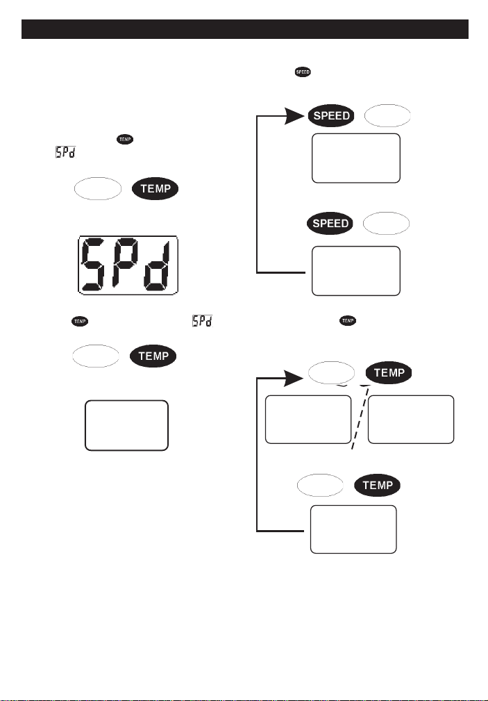
Modes
Press the key to toggle between the SPEED and
TRIP LOG modes.
>
/
SPd
Press for 15 Seconds
3. To disable the simulation mode, press and
hold the
displayed again. The display will revert to 0.0.
key for 15 seconds until is
Press for 15 Seconds
The instrument always powers up into the SPEED
mode.
>
/
Log
Press and hold the key to display the TOTAL
LOG , release to show the temperature.
>
/
oF oC
>
796
/
4
SPEED 2100 Installation and Operation ManualNAVMAN
Page 5
Trip Log Reset
CAL
Select the TRIP LOG mode. Press and hold the
key until the display resets to zero.
Tot al Log Reset
Press and hold the and / keys while powering
up and hold for at least 30 seconds until the
TOTAL LOG is reset.
Press and hold
2 Instrument Setup
The instrument must be calibrated after installation
to ensure accurate speed readings.
Selecting units of measure
The SPEED 2100 will indicate boat speed in Knots
(nautical miles), MPH (statute miles) or KPH
(kilometres). To change the current setting perform
the following steps:
1. Power up the unit while holding down the
Hold down during power up
2. When the unit is on, release the
display will indicate the current display unit with:
Knots (nautical miles)
MPH (statute miles)
key.
key. The
Press for 30 seconds
Information will now be indicated in the selected
display unit.
Calibrating SPEED Against a Known
Reference
1. Select SPEED mode
2. Press and hold the
seconds.
3. Release both keys when the display shows the
following:
4. While travelling at the known speed , press the
key to increase the displayed speed or the
key to decrease the reading.
5. When the correct reading is indicated, press
and hold the
seconds.
6. Release both keys when the display shows the
following:
and keys for 5
and keys again for two
KPH (kilometres)
3. To select the display unit desired, use the
and keys to change the value.
4. To exit this mode, press and hold both the
and keys simultaneously for one second.
Press and hold to exit
NAVMAN
SPEED 2100 Installation and Operation Manual
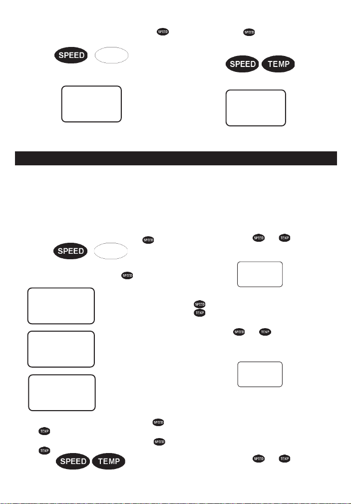
SPd
Calibrating DISTANCE Against a
Known Reference
1. Select the TRIP LOG mode.
2. Press and hold the
seconds.
and keys for 5
5
Page 6

3. Release both keys when the display shows the
following:
CAL
4. The TRIP LOG reading will reset to 0.0.
5. Travel a known distance.
6. If the display indicates a reading different from
the known distance, press the
increase the reading or the
decrease the reading.
7. When the correct reading is indicated, press
and hold the
seconds.
8. Release both keys when the display shows the
following:
and keys again for two
key to
key to
LOg
°F / °C Selection
Press and hold the key while powering up the
instrument. The display will indicate the current unit
of measure.
4. If the temperature reading indicated is
incorrect, press the key to increase the
reading or the
reading.
5. When the correct reading is indicated, press
and hold the
seconds.
6. Release both keys when the display shows the
following:
key to decrease the
and keys again for two
oF oC
oF oC
Press either the or key until the desired unit
of measure is displayed. Press and hold the
keys for two seconds. The current temperature
will be displayed.
Temperature Calibration
T o calibrate the TEMPERATURE:
1. Select the TEMP mode.
2. Press and hold the
seconds.
3. Release both keys when the display shows the
following:
Press for 5 seconds
and
and keys for 5
CAL
6
SPEED 2100 Installation and Operation ManualNAVMAN
Page 7

3 Installation
Location
The SPEED 2100 is designed for above or below
deck installation. Select a position that is:
• On a flat surface
• At least 300mm (12”) from a compass
• At least 500mm (20”) from any radio
• Easy to read by the helmsman and crew
• Protected from physical damage
• Accessible to electrical cable connections
Instrument
Panel
Mounting
The instrument panel must be 3mm to 19mm
(1/8” to 3/4”) in thickness.
• Drill a 51mm (2”) hole in the instrument panel.
• Remove brackets and insert the instrument so
the back is flush with the instrument panel.
• Slide the bracket over the instrument and
tighten the mounting nut until secure.
NAVMAN
51mm (2”)
Instrument
Sealing
Gasket
SPEED 2100 Installation and Operation Manual
Hole
Mounting Nut
Mounting
Bracket
7
Page 8
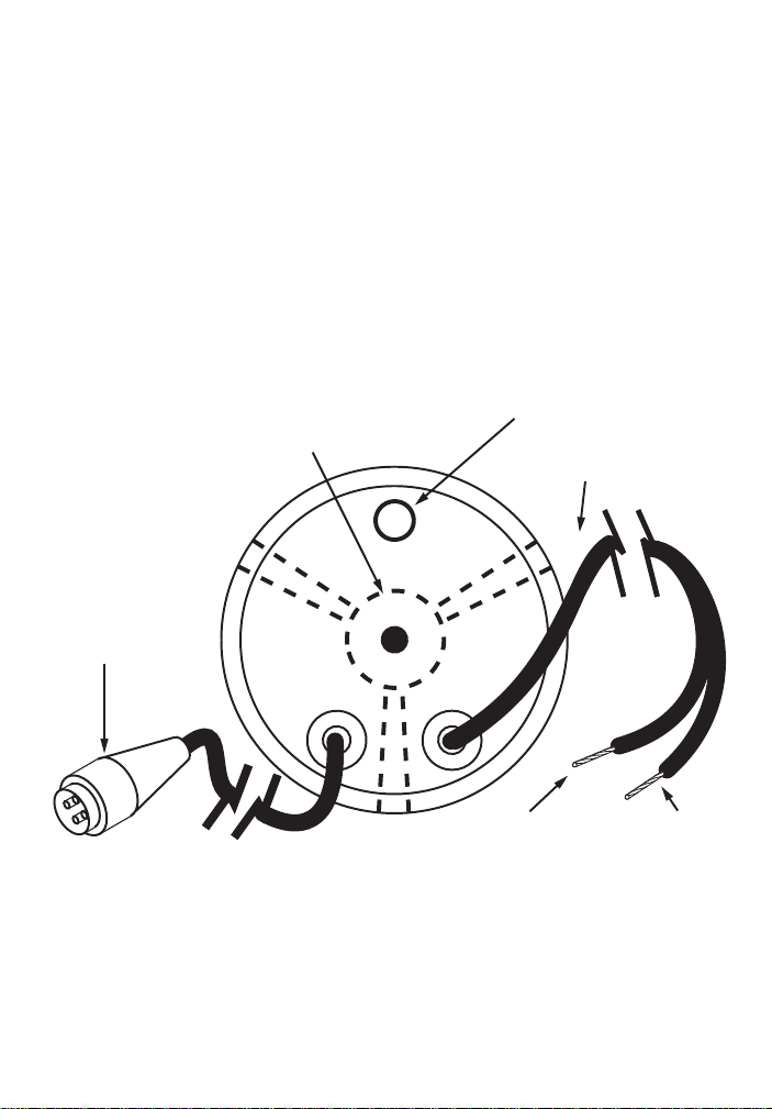
Wiring Connection
• Keep electrical and transducer cables away
from alternator or other noise generating
electrical cables. Avoid connecting the
instrument to power circuits that share loads
with ignition, alternators, inverters and radio
transmitters. Electrical power supply
connections should always be as short as
possible.
• Connect the red wire to the positive supply via
a 1 amp fuse or a 1 amp circuit breaker.
Connect the black wire to the electrical ground.
BRACKET
4 PIN
CONNECTOR
• Connect the 4 pin Fuji connector to the speed
and temperature transducer cable connector.
Extension cables are available if the
transducer cable is too short.
BUZZER
600mm (24”)
POWER CORD
RED
(+) TERMINAL
8
SPEED 2100 Installation and Operation ManualNAVMAN
BLACK
(-) TERMINAL
Page 9

Appendix A - Specifications
• Size
Mount
51mm diameter hole
Depth behind face plate
95mm max.
Display
3-character LCD
• Colour
Black with texture on bezel.
• Backlighting
Red coloured diffused lighting for display.
• Water Integrity
Front will withstand direct water spray.
• Impeller
• Speed units and resolution
0-19.9 and then 20-50 in knots, MPH or KPH
(depending on transducer type),
• Trip Log
0-999 miles, non-volatile, resetable
(0.00-9.99 read in hundredths, 10.0-99.9 read in
tenths, 100-999 read in whole numbers).
• Total Log
0-999 miles, non-volatile, resetable
(0.00-9.99 read in hundredths, 10.0-99.9 read in
tenths, 100-999 read in whole numbers).
• Temperature Sensor
10 Kohm thermistor at 25°C.
• Temperature Range
0.0°C to 37.7°C (32.0°F to 99.9°F).
• Operating Voltage
8 VDC to 16.5 VDC.
• Operating Temperature
0°C to 50°C (32°F to 122°F).
• Current Drain
70 mA max.
• RF Interference
<6 dB quieting on any marine radio channel
(with 3 dB gain antennae) within one metre of
the SPEED 2100. Complies with CE EMC
standards EN50081-1 and EN50082-1.
Display is backlit for
Night Operation
Change Value Up
NAVMAN
888
SPEED 2100 Installation and Operation Manual
NAVMAN
SPEEDPower
>
/
Change Value Down
9
Page 10

Appendix B - Troubleshooting Chart
No display:
1. Check DC power connections and DC polarity with voltmeter.
2. Check fuse.
No speed or log readings:
Check and make sure that the paddlewheel on the impeller is not
stuck or fouled with growth.
Inaccurate speed readings:
1. Re-calibrate
2. Check paddlewheel
Erratic speed readings while moving:
1. Check to make sure that the impeller is aligned fore and aft.
2. Review the installation for possible erratic water flow over the impeller.
Erratic readings only while engine is running:
1. Re-route power and transducer cables away from engine, ignition
wires and battery cables.
2. Add feed-through filter capacitor on the positive terminal of the ignition
coil.
3. Add an alternator whine filter to alternator.
4. Replace spark plug wire with resistive type.
No temperature reading or is inaccurate:
1. Check calibration.
2. Check for break in cable.
Simulation mode:
At power up, if all the segments display for 5 seconds then the
instrument is in simulation mode.
10
SPEED 2100 Installation and Operation ManualNAVMAN
Page 11

Appendix C - How to contact us
NORTH AMERICA
NAVMAN USA INC.
18 Pine St. Ext.
Nashua, NH 03060.
Ph: +1 603 577 9600
e-mail: sales@navmanusa.com
OCEANIA
New Zealand
Absolute Marine Ltd.
Unit B, 138 Harris Road,
East Tamaki, Auckland.
Ph: +64 9 273 9273
e-mail:
navman@absolutemarine.co.nz
Papua New Guinea
Lohberger Engineering
Lawes Road, Konedobu
PO Box 810
Port Moresby
Ph: +675 321 2122
e-mail: loheng@online.net.pg
Australia
NAVMAN AUSTRALIA PTY
Limited
Unit 6 / 5-13 Parsons St,
Rozelle, NSW 2039, Australia.
Ph: +61 2 9818 8382
e-mail: sales@navman.com.au
SOUTH AMERICA
Argentina
Costanera UNO S.A.
Av Presidente R Castillo y
Calle 13
1425 Buenos Aires, Argentina.
Ph: +54 11 4312 4545
e-mail:
purchase@costanerauno.com.ar
Website:
www.costanerauno.ar
Brazil
REALMARINE
Estrada do Joa 3862,
CEP2611-020,
Barra da Tijuca, Rio de Janeiro,
Brasil.
Ph: +55 21 2483 9700
e-mail:
vendas@marinedepot.com.br
Equinautic Com Imp Exp de
Equip Nauticos Ltda.
Av. Diario de Noticias 1997 CEP
90810-080, Bairro Cristal, Porto
Alegre - RS, Brasil.
Ph: +55 51 3242 9972
e-mail:
equinautic@equinautic.com.br
NAVMAN
SPEED 2100 Installation and Operation Manual
ASIA
China
Peaceful Marine Electronics Co. Ltd.
Hong Kong, Guangzhou,
Shanghai, Qindao, Dalian.
E210, Huang Hua Gang Ke Mao
Street, 81 Xian Lie Zhong Road,
510070 Guangzhou, China.
Ph: +86 20 3869 8784
e-mail: sales@peaceful-marine.com
Website: www.peaceful-marine.com
India
Access India Overseas Pvt
A-98, Sector 21, Noida, India
Ph: +91 120 244 2697
e-mail: vkapil@del3.vsnl.net.in
Indonesia
Polytech Nusantara
Graha Paramita 2nd Floor
Jln Denpasar Raya Blok D2
Kav 8 Kuningan, Jakarta 12940
Tel: 021 252 3249
Korea
Kumhomarine Technology Co., Ltd.
#604-842, 2F, 1118-15,
Janglim1-Dong, Saha-Gu
Busan, Korea
Ph: +82 51 293 8589
e-mail: info@kumhomarine.com
Website: www.kumhomarine.com
Maldives
Maizan Electronics Pte. Ltd.
8 Sosunmagu Male
Ph: +960 78 2444
e-mail:
ahmed@maizan.com.mv
Singapore
RIQ PTE Ltd.
81, Defu Lane 10, Hah Building,
#02-00 Singapore 539217
Ph: +65 6741 3723
e-mail: riq@postone.com
Taiwan
Seafirst International Corporation
No.281, Hou-An Road
Chien-Chen Dist.
Kaohsiung, Taiwan R.O.C.
Ph: +886 7 831 2688
e-mail: seafirst@seed.net.tw
Thailand
Thong Electronics (Thailand)
Company Ltd.
923/588 Thaprong Road,
Mahachai,
Muang, Samutsakhon 74000,
Thailand.
Ph: +66 34 411 919
e-mail: thonge@cscoms.com
Vietnam
Haidang Co. Ltd.
16A/A1E, Ba thang hai St.
District 10, Hochiminh City.
Ph: +84 8 86321 59
e-mail: sales@haidangvn.com
Website: www.haidangvn.com
MIDDLE EAST
Lebanon and Syria
Letro, Balco Stores,
Moutran Street, Tripoli VIA Beirut.
Ph: +961 6 624512
e-mail: balco@cyberia.net.lb
United Arab Emirates
Kuwait, Oman, Iran & Saudi Arabia
Abdullah Moh’d Ibrahim
Trading, opp Creak Rd.
Baniyas Road, Dubai.
Ph: +971 4 229 1195
e-mail: mksq99@email.com
AFRICA
South Africa
Pertec (Pty) Ltd Coastal,
Division No.16 Paarden Eiland Rd.
Paarden Eiland, 7405
Postal Address: PO Box 527,
Paarden Eiland 7420
Cape Town, South Africa.
Ph: +27 21 511 5055
e-mail: info@kfa.co.za
EUROPE
France, Belgium and
Switzerland
PLASTIMO INTERNATIONAL
15, rue Ingénieur Verrière,
BP435,
56325 Lorient Cedex.
Ph: +33 2 97 87 36 36
e-mail: plastimo@plastimo.fr
Website: www.plastimo.fr
Germany
PLASTIMO DEUTSCHLAND
15, rue Ingénieur Verrière
BP435- 56325 Lorient Cedex.
Ph: +49 6105 92 10 09
+49 6105 92 10 10
+49 6105 92 10 12
e-mail:
plastimo.international@plastimo.fr
Website: www.plastimo.de
Italy
PLASTIMO ITALIA
Nuova Rade spa, Via del Pontasso 5
I-16015 CASELLA SCRIVIA (GE).
Ph: +39 1096 8011
e-mail: info@nuovarade.com
Website: www.plastimo.it
Holland
PLASTIMO HOLLAND BV.
Industrieweg 4-6,
2871 RP SCHOONHOVEN.
Ph: +31 182 320 522
e-mail: info@plastimo.nl
Website: www.plastimo.nl
United Kingdom
PLASTIMO Mfg. UK Ltd.
School Lane - Chandlers Ford
Industrial Estate,
EASTLEIGH - HANTS S053 ADG.
Ph: +44 23 8026 3311
e-mail: sales@plastimo.co.uk
Website: www.plastimo.co.uk
Sweden, Denmark or Finland
PLASTIMO NORDIC AB.
Box 28 - Lundenvägen 2,
47321 HENAN.
Ph: +46 304 360 60
e-mail: info@plastimo.se
Website: www.plastimo.se
Spain
PLASTIMO ESPAÑA, S.A.
Avenida Narcís Monturiol, 17
08339 VILASSAR DE DALT,
(Barcelona).
Ph: +34 93 750 75 04
e-mail: plastimo@plastimo.es
Website: www.plastimo.es
Portugal
PLASTIMO PORTUGAL
Avenida de India N°40
1300-299 Lisbon
Ph: +351 21 362 04 57
e-mail:
plastimo@siroco-nautica.pt
Other countries in Europe
PLASTIMO INTERNATIONAL
15, rue Ingénieur Verrière
BP435
56325 Lorient Cedex, France.
Ph: +33 2 97 87 36 59
e-mail:
plastimo.international@plastimo.fr
Website: www.plastimo.com
REST OF WORLD /
MANUFACTURERS
Navman NZ Limited
13-17 Kawana St. Northcote.
P.O. Box 68 155 Newton,
Auckland, New Zealand.
Ph: +64 9 481 0500
e-mail:
marine.sales@navman.com
Website: www.navman.com
59
Page 12

Made in New Zealand
MN000206A
SPEED 2100
Lon 174° 44.535’E
Lat 36° 48.404’S
NAVMAN
 Loading...