

Page 1
SmartCraft Gateways
For si ngle an d dual en gine ap plica tions
Installation and
Operation Manual
w w w . n a v m a n . c o m
NAVMAN
Page 2

IMPORTANT SAFETY INFORMATION
CAUTION
!
!
DANGER
WARNING
CAUTION
!
!
WARNING
CAUTION
!
CAUTION
!
!
CAUTION
DANGER
WARNING
Please read carefully before installation and use.
This is the safety alert symbol. It is used to alert you to potential
personal injury hazards, Obey all safety messages that follow this
symbol to avoid possible injury or death.
WARNING indicates a potentially hazardous situation which, if not
avoided, could result in death or serious injury
CAUTION indicates a potentially hazardous situation which, if not
avoided, could result in minor or moderate injury.
CAUT ION used without the safe ty aler t s ymbol indic ates a
potentially hazardous situation which, if not avoided, may result
in property damage.
FCC Statement
Note: This equipment has been tested and found to comply with the limits for a Class B
digital device, pursuant to Part 15 of the FCC Rules. These limits are designed to provide
reasonable protection against harmful interference in a normal installation. This equipment
generates, uses and can radiate radio frequency energy and, if not installed and used in
accordance with the instructions, may cause harmful inter ference to radio communications.
However, there is no guarantee that interference will not occur in a particular installation.
If this equipment does cause harmful interference to radio or television reception, which
can be determined by turning the equipment off and on, the user is encouraged to try to
correct the interference by one or more of the following measures:
Reorient or relocate the receiving antenna.
Increase the separation between the equipment and receiver.
Connect the equipment into an output on a circuit different from that to which the
receiver is connected.
Consult the dealer or an experienced technician for help.
A shielded cable must be used when connecting a peripheral to the serial por ts.
Industr y Canada
Operation is subject to the following t wo conditions: (1) this device may not cause
interference, and (2) this device must accept any interference, including inter ference that
may cause undesired operation of the device.
Page 3

Contents
1 Introduction ..........................................................................................................................................4
1-1 SmartCraft data available from different engines . . . . . . . . . . . . . . . . . . . . . . . . . . . . . . . . .
1-2 What comes with your gateway? . . . . . . . . . . . . . . . . . . . . . . . . . . . . . . . . . . . . . . . . . . . . . . . . . . 5
2 Installation ............................................................................................................................................
2-1 Connecting the gateway to the SmartCraft system . . . . . . . . . . . . . . . . . . . . . . . . . . . . . . .
2-2 Connecting the gateway to the Navman instrument . . . . . . . . . . . . . . . . . . . . . . . . . . . . . .
2-3 Installation . . . . . . . . . . . . . . . . . . . . . . . . . . . . . . . . . . . . . . . . . . . . . . . . . . . . . . . . . . . . . . . . . . . . . . . 7
3 Operation with a Navman FISH 4380 .......................................................................................................
3-1 Setting up the FISH 4380 for Smartcraft . . . . . . . . . . . . . . . . . . . . . . . . . . . . . . . . . . . . . . . . . . .
3-2 SmartCraft engine data displays . . . . . . . . . . . . . . . . . . . . . . . . . . . . . . . . . . . . . . . . . . . . . . . . . 10
3-3 Troll control . . . . . . . . . . . . . . . . . . . . . . . . . . . . . . . . . . . . . . . . . . . . . . . . . . . . . . . . . . . . . . . . . . . . .
3-4 Trim indicator . . . . . . . . . . . . . . . . . . . . . . . . . . . . . . . . . . . . . . . . . . . . . . . . . . . . . . . . . . . . . . . . . . .12
3-5 Engine fault alarms . . . . . . . . . . . . . . . . . . . . . . . . . . . . . . . . . . . . . . . . . . . . . . . . . . . . . . . . . . . . . . 12
3-6 Engine fault lists . . . . . . . . . . . . . . . . . . . . . . . . . . . . . . . . . . . . . . . . . . . . . . . . . . . . . . . . . . . . . . . . .
3-7 SmartCraft setup data . . . . . . . . . . . . . . . . . . . . . . . . . . . . . . . . . . . . . . . . . . . . . . . . . . . . . . . . . . .14
3-8 SmartCraft calibration . . . . . . . . . . . . . . . . . . . . . . . . . . . . . . . . . . . . . . . . . . . . . . . . . . . . . . . . . . .
4 Operation with a Navman TRACKFISH 6600 ...........................................................................................
4-1 Setting up the TRACKFISH 6600 for Smartcraft . . . . . . . . . . . . . . . . . . . . . . . . . . . . . . . . . . .
4-2 SmartCraft engine data displays . . . . . . . . . . . . . . . . . . . . . . . . . . . . . . . . . . . . . . . . . . . . . . . . . 19
4-2-1 Tank status display . . . . . . . . . . . . . . . . . . . . . . . . . . . . . . . . . . . . . . . . . . . . . . . . . . . . . . . . . . . . .
4-2-2 Customising the engine data displays . . . . . . . . . . . . . . . . . . . . . . . . . . . . . . . . . . . . . . . . .
4-3 Troll control . . . . . . . . . . . . . . . . . . . . . . . . . . . . . . . . . . . . . . . . . . . . . . . . . . . . . . . . . . . . . . . . . . . . .
4-4 Trim indicator . . . . . . . . . . . . . . . . . . . . . . . . . . . . . . . . . . . . . . . . . . . . . . . . . . . . . . . . . . . . . . . . . . .21
4-5 Engine fault alarms . . . . . . . . . . . . . . . . . . . . . . . . . . . . . . . . . . . . . . . . . . . . . . . . . . . . . . . . . . . . . .22
4-6 Engine fault lists . . . . . . . . . . . . . . . . . . . . . . . . . . . . . . . . . . . . . . . . . . . . . . . . . . . . . . . . . . . . . . . . .
4-7 SmartCraft setup data and calibrations . . . . . . . . . . . . . . . . . . . . . . . . . . . . . . . . . . . . . . . . . .
5 Operation with a Navman FISH 4600 .....................................................................................................27
5-1 Setting up the FISH 4600 for Smartcraft . . . . . . . . . . . . . . . . . . . . . . . . . . . . . . . . . . . . . . . . . .28
5-2 SmartCraft engine data displays . . . . . . . . . . . . . . . . . . . . . . . . . . . . . . . . . . . . . . . . . . . . . . . . .28
5-3 Troll control . . . . . . . . . . . . . . . . . . . . . . . . . . . . . . . . . . . . . . . . . . . . . . . . . . . . . . . . . . . . . . . . . . . . .30
5-4 Trim indicator . . . . . . . . . . . . . . . . . . . . . . . . . . . . . . . . . . . . . . . . . . . . . . . . . . . . . . . . . . . . . . . . . . .30
5-5 Engine fault alarms . . . . . . . . . . . . . . . . . . . . . . . . . . . . . . . . . . . . . . . . . . . . . . . . . . . . . . . . . . . . . . 31
5-6 Engine fault lists . . . . . . . . . . . . . . . . . . . . . . . . . . . . . . . . . . . . . . . . . . . . . . . . . . . . . . . . . . . . . . . . . 31
5-7 SmartCraft setup data and calibrations . . . . . . . . . . . . . . . . . . . . . . . . . . . . . . . . . . . . . . . . . .32
Appendix A - Specifications .....................................................................................................................
20
20
21
22
23
4
6
6
7
8
9
11
13
16
18
19
36
Page 4

1 Introduction
The Navman SmartCraf tTM gateway connec ts
one or two SmartCraft capable Mercury
petrol/gasoline engines to a SmartCraft capable
Navman instrument, such as the FISH 4380, FISH
4600 or TRACKFISH 6600. The single gateway is
for single engines, the dual gateway is for twin
engines.
Adding the gateway extends the functions of the
Navman instrument, allowing the instrument to:
Display engine data, such as speed, RPM,
pressures, tank levels.
Control troll speed and display trim.
Sound an alarm if it detects an abnormal
engine condition.
1-1 SmartCraft d ata available from diffe rent engines
The SmartCraft engine data available in a system depends on the type of engine. SmartCraft is a digital
engine network provided on some later model (2002 +) Mercury and Mariner Engines, both in-board and
out-board.
This manual describes:
How to install a Navman SmartCraft gateway.
How to use the Smar tCraft functions of a
Navman SmartCraft capable instrument.
Refer to the separate Navman instrument
Installatio n and Operation Manu al for
information on how to install and use the
instrument.
The engine data available in a system depends
on the type of engine used (see section 1-1). The
gateway replaces any fuel flow sensors that might
be plugged into the Navman
instrument .
It is vital to read this document and the
associated SmartCraft and Navman installation
and operation manuals before installing or using
the system.
Engine type
6.2 L
8.1 L
Engine data available
Steering Angle
Fuel level
Oil temperature
Oil Pressure
Engine Trim
Water Pressure
Engine temperature
Fuel Flow
Fuel Level
Engine voltage
Pitot water (boat) speed
RPM
4 Stroke 30 - 60
NAVMAN SmartCraft Gateways Installation and Operation Manual4
Optimax 75- 115
V-6 EFI
Optimax 135-250
Optimax 225 DTS
Verado
Mercruiser 4.3 L
Mercruiser 5.0 L
Mercruiser 5.7 L
Mercruiser
Mercruiser
496 HO
Page 5
1-1-1 Tanks and sensors
Engines can have optional level sensors fit ted:
A two-stroke engine can have one sensor
fitted to its oil tank, and one additional sensor
fitted to a fuel, oil, water or waste tank.
A four stroke engine can have one or two
sensors fitted to its fuel, water or waste tanks.
1-2 What comes with your gateway?
Built-in cable to the Navman
instrument, 1 m (3.3 ft) long
Built-in cable to the SmartCraft system, 300
mm (1 ft.) long
If level sensors are fitted: the tank levels can be
displayed; there are alarms for low tank levels;
the tanks must be set up and calibrated (see
following sections:
FISH 4380 : Section 3-8-1
TRACKFISH 660 0 : Section 4-7-1
FISH 4600 : Section 5-7-1
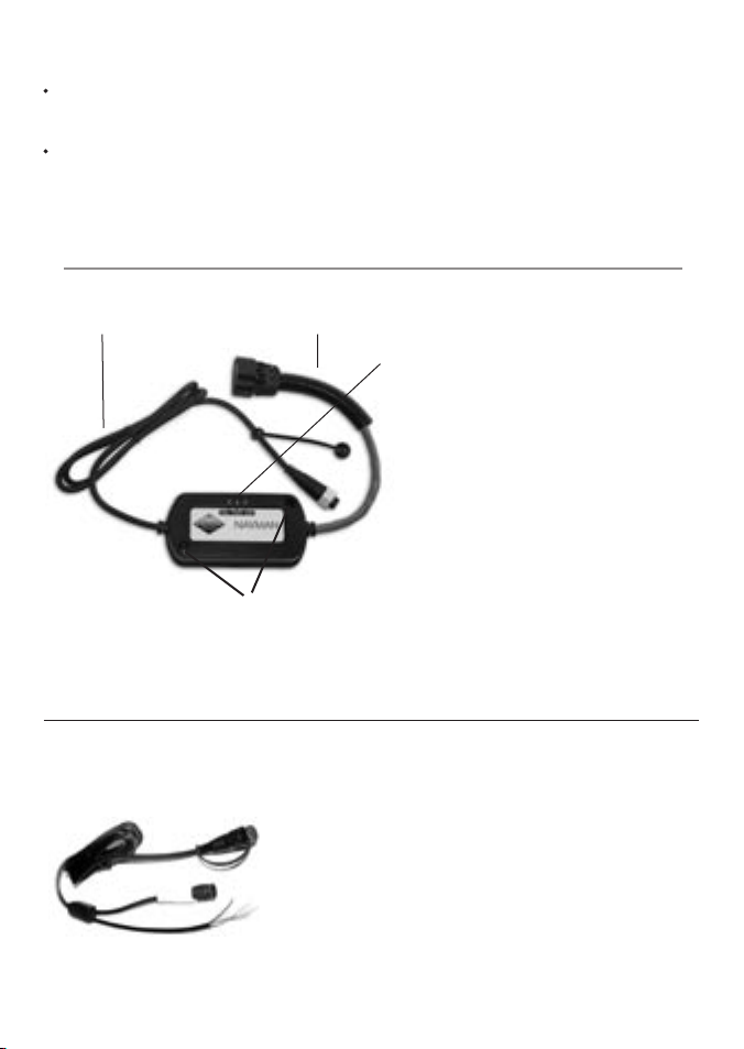
SmartCraft Gateway
Gateway LEDS:
NAV (orange): Flashes fast when the gateway is
exchanging data with the Navman instrument
and the engine key is on.
PWR (green): On when power and the engine
key are on.
CAN (red): Flashes fast when the gateway is
exchanging data with the Smar tCraft engine(s)
and the engine key is on.
Holes for mounting screws
Optiona l extras for Smar tCraft
AA002237
Also supplied:
• Two mounting screws (8 gauge x 5/8 inch,
Pan pozi, self tapping, stainless steel);
• Warranty card;
• This manual.
Power/fuel splitter cable
A power/fuel splitter cable (‘Y’ cable) is required
for Navman instruments that do not have a
separate fuel sensor connector (such as the FISH
4380, see section 2-2). This cable is included in
hardware pack ages AA005022 and AA005023
and is also available separately from your Navman
dealer.
Also see Appendix-C
5NAVMAN SmartCraft Gateways Installation and Operation Manual
Page 6

2 Installation
CAUTION
!
!
CAUTION
DANGER
WARNING
CAUTION
!
!
CAUTION
DANGER
WARNING
A system in a boat comprises:
a. One or two SmartCraft capable petrol/
gasoline engines; the data available depends
on engine type and the sensors fit ted (see
section 1-1).
b. A single or dual engine gateway.
c. A SmartCraft capable Navman instrument,
such as the FISH 4380, FISH 4600 or
TRACKFISH 660 0.
d. Other optional Navman instruments and
SmartCraft displays. See Appendix-C
2-1 Connecting the gateway to the SmartCraft system
Using a Nav man cable adapt or: Use a Navman cable adaptor in a single engine system which does
not have optional SmartCraft displays. However, a SmartCraft junction box should be used if future
expansion of the SmartCraft system is planned.
SmartCraft harness 879982T-x
(x = length in feet)
Petrol
engine
Using a SmartCraft junc tion box: Connec t the gateway to a Smar tCraft Junction box in a twin engine
system or in any system with optional SmartCraft displays.
SmartCraft harness 879981T-x
Petrol
engine
(x = length in feet)
Correct installation is critical to the
performance of the unit. Before starting
installation, it is vital to read this manual and
the documentation that comes with the
other parts. Then plan the installation and
select where the equipment and cables will
be located.
Ensure that any holes that you cut will not
weaken the boat ’s structure. If in doubt,
consult a qualified boat builder.
SmartCraft cable adaptor 892452A01
Single engine gateway
Fit optional SmartCraft displays, or
fit Mercur y weather cap 859318T-2
Petrol
engine
There must be two SmartCraft Terminators in any SmartCraft Installation. The Mercur y harness
84-879982T-x has two terminators built-in; the Mercury harness 84-879981T-x has one terminator
built-in.Terminators must be positioned at the fur thermost ends of the Smar tCraf t network.
Refer to a Mercur y SmartCraft manual, such as Wiring f or SmartCraft Ga uges (Mercury par t 90-879939),
for details of installation configurations and requirements, alternative termination methods and
additional SmartCraft components such as harnesses, junction boxes and terminators. Also see
Appendix C
To use the SmartCraft functions, install the Smar tCraft gateway (see section 2), then go to the System
setup menu on the Navman Instrument and turn SmartCraft to On (See Setup > System menu).
Optional
SmartCraft junc tion box
878492B-4
NAVMAN SmartCraft Gateways Installation and Operation Manual6
Single or dual engine gateway
Page 7
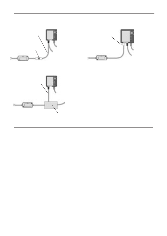
2-2 Connecting the gateway to the Navman instrument
For a Navman instrument without a white
fuel sensor connector (such as a FISH 4380):
Power/fuel s plitter
cable (‘ Y’ cable)
Plug gateway into
white conne ctor
FISH 4380
Other wi ring,
refer to the
instrum ent’s
manual
For any Navman instrument, using a NavBus junction box to connect to power/data cable (black
power connector):
Power/data
cable
Other wi ring,
refer to the
instrum ent’s
manual
NavBus
juncti on box
For a Navman instrument with a white fuel
sensor connector (such as a FISH 4600 or
TRACKFISH 6600):
Plug gateway into
white conne ctor
The wires from the gateway to the Navman
instrument cable can be connected to the
instrument’s power/data cable. This option is not
normally necessary. For more information, refer to
your Navman dealer.
Cut white connec tor off gateway cable. Connect
five gateway cable wires (red, black, blue,
orange, brown) to the same colour wires in the
power/data cable. An optional Navman NavBus
junction box simplifies wiring.
FISH 4600,
TRACKFISH
6600
Other wi ring,
refer to the
instrum ent’s
manual
2-3 Installation
1 Plan the installation: select where the
equipment and wiring will be installed.
Ensure that gateway can be located on a
panel near the Navman instrument, where
it will not inter fere with the operation of the
boat. (eg: cables are long enough for the
installation planned)
2 Screw the gateway to the panel using the
screws provided.
3 Connect the gateway (see sec tions 2-1 and
2-2). Secure the cables at regular intervals.
4 Power up, set up and test the system. Check
the gateway LEDs:
NAV (orange): Flashes fast when gateway
is exchanging data with the Navman
instrument and the engine key is on.
PWR (green): On when power and the
engine key are on.
CAN (red): Flashes fast when gateway
is exchanging data with the Smar tCraft
engine(s) and the engine key is on.
Important:
1 Do not connect any Navman fuel sensors to
the Navman instrument.
2 It is not necessar y to wire any Navman
instrument for auto power on.
3 The Navman Smar tCraf t capable instrument
sends SmartCraft data to other
Navman instruments connected by NavBus.
To connect other instruments by NavBus, see
the instrument’s installation and operation
manual. Turn NavBus on in all Navman
instruments connected by NavBus; for
example, for a Fish 4380, in the Com ms setup
menu, turn NavBus to On
.
4 A gateway does not provide data for system
link gauges.
5 To use speed troll control, the Navman
instrument must have a Navman
paddlewheel speed sensor connected.
7NAVMAN SmartCraft Gateways Installation and Operation Manual
Page 8

3 Operation with a Navman FISH 4380
Before a SmartCraft gateway is connec ted, the FISH 4380 functions normally, with no Smar tCraf t
functions. When a Smar tCraft gateway is connected and SmartCraft is turned On (see section 3-1),
SmartCraft functions become available and some standard func tions change.
SmartCraft features
Data displays
Engine performance and tank level displays .....................................................................................................................
See section 3-2
Troll control
Automatically maintains a set engine idle RPM or idle boat speed ..........................................................................
See section 3-3
Trim indicator
Displays the trim angle when engine trim is adjusted ...................................................................................................
See section 3-4
Alarms
SmartCraft engine fault alarms ...............................................................................................................................................
See section 3-5
Engine fault list, a list of active SmartCraft engine fault alarms ..................................................................................
See section 3-6
Engine fault history, a list of past SmartCraft engine fault alarms .............................................................................
See section 3-6
Tank low level alarms ..................................................................................................................................................................
See section 3-2
Setup data and calibrations
SmartCraft setup data ................................................................................................................................................................
See sections 3-1 and 3-7
SmartCraft calibrations, Tanks, Trim and Steering angle. ...............................................................................................
See section 3-8
The SmartCraft data available depends on the engine type and the sensors fitted (see section 1-1). To disable
the SmartCraft functions, turn SmartCraft to Off (see sec tion 3-1); the instrument will now use any
Navman fuel sensors which are connected.
To use the SmartCraft functions and not the sonar functions, turn Sonar to Off (see section 3-1).
Changes to s tandard func tions with Smart Craft
If no fuel tanks have an optional level sensor fitted (see section 1-1-1), then the Smartcraft fuel flow is
If each fuel tank has an optional level sensor fitted (see section 1-1-1), then these tank levels are
key: When using troll control, pressing can display the troll window. Press a
second time to display the normal menu of options.
Fuel disp lay: The fuel display functions normally, with fuel and speed data coming from the
SmartCraft system rather than from separate sensors connected to the FISH 4380.
Fuel setup options
used to calculate fuel remaining. The fuel setup data is the same as the standard FISH 4380. You must
tell the FISH 4380 when you add or remove fuel (see the FISH 4380 Installation and Operation manual).
used to calculate fuel remaining. In the Fuel display, Used changes to Trip used, and the only
fuel setup option is Clear trip use d
is reset to zero by selecting Clear trip used in the fuel setup menu. You do not tell the FISH
4380 when you add or remove fuel.
:
. Trip used measures the volume of fuel used until it
NAVMAN SmartCraft Gateways Installation and Operation Manual8
Page 9
Engine h ours: Engine hours on the Log display come from the Smar tCraft system.
It can not be reset.
Simulate mode: Data from the SmartCraf t engine(s) and sensors is simulated in Simulate mode. The
SmartCraft features simulated will probably dif fer from the features available in your system.
For more information, see the FISH 4380 Installati on and Operation manual.
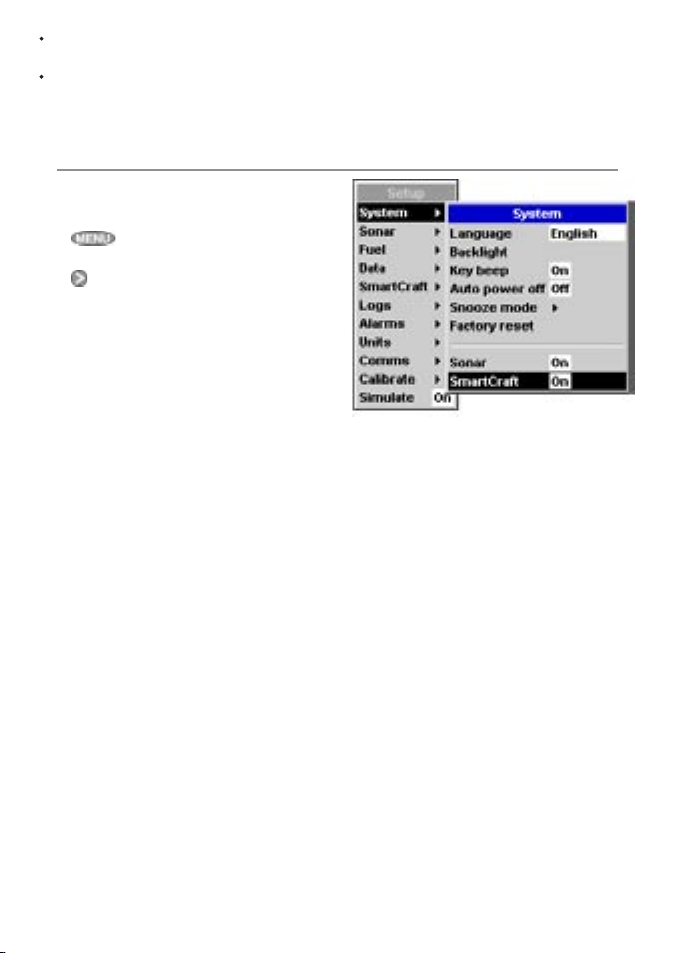
3-1 Setting up the FISH 4380 for Smartc raft
These features can be used only when the
optional single or twin engine SmartCraft
Gateway has been installed.
Press
then selec t SmartCraft.
Press
Note: NavBus will be turned on when SmartCraft
is turned on.
twice to display the Setup menu,
to select On or Off
Sonar
Select:
Off: The sonar transducer and the sonar
functions are disabled. Choose Off to use
the instrument’s SmartCraft functions only,
On: Normal sonar operation.
SmartCraft
Select:
Off: The SmartCraft functions and NavBus
are disabled. The instrument will now use any
Navman fuel sensors which are connected.
On: Normal SmartCraft operation.
9NAVMAN SmartCraft Gateways Installation and Operation Manual
Page 10

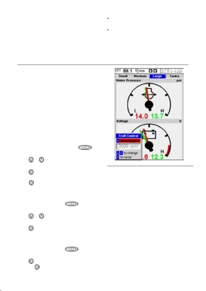
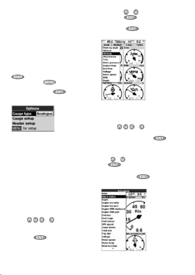
3-2 SmartCraf t engine data dis plays
To display the SmartCraft data, press and
select SmartCraft, then press
or to select one of the four SmartCraft displays,
shown below.
For the Small, Medium and Large gauges:
The factory default has gauges appropriate to
the type of engine. To change what gauges
are displayed, see section 3-7: Gauge setup.
Small: Six small ‘analogue’ gauges: Medium: Two medium & two small ‘analogue’
, or
Header
data
If the boat has twin engines, the red needle
or number shows port data, green shows
starboard data.
The gauges can be set up to be analogue
(dial) or digital (number) (see section 3-7:
Gauge type and Spe ed range).
Each display has three items of header data. To
select what data is displayed, see section 3-7:
Header setup.
gauges
Large : Two large ‘analogue’ gauges
NAVMAN SmartCraft Gateways Installation and Operation Manual10
Tanks: Tank levels (see next page)
Page 11
Tank level disp lay
The tank level display shows the levels from the
optional level sensors in one or two tank s per
engine (see section 1-1-1).
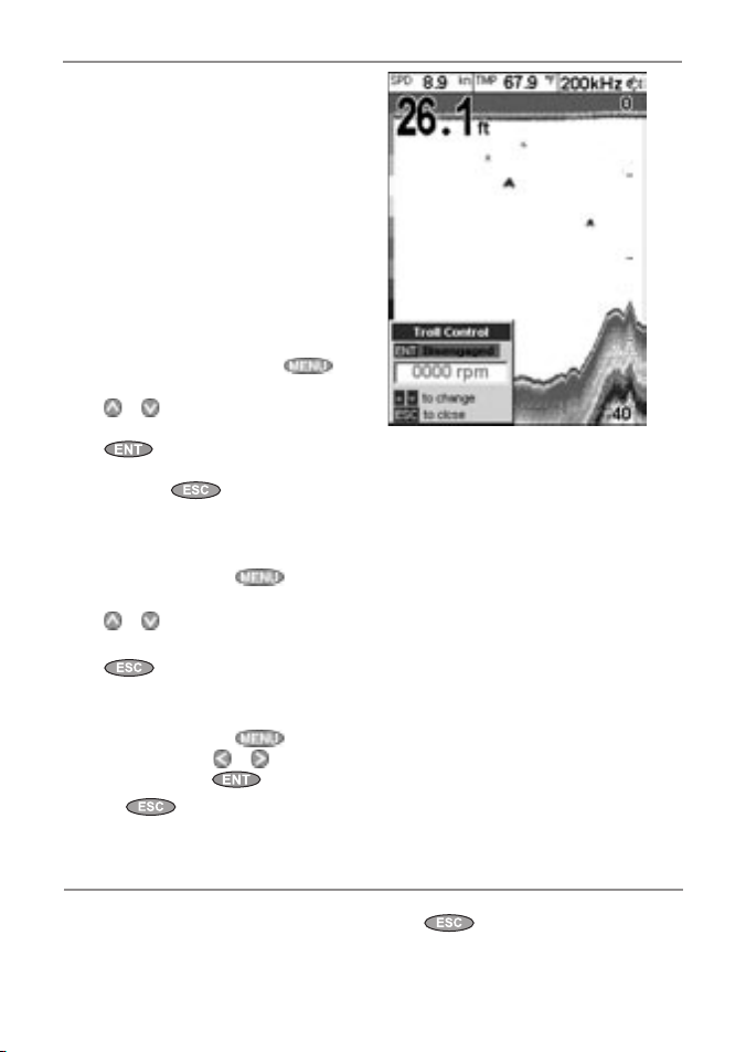
3-3 Troll control
Troll control allows adjustment of the engine’s
idle speed from the Navman instrument. Troll
control automatically controls the engine idle
speed to maintain a set engine RPM or boat
speed.
To use troll control, set Troll window to On
idle or Always and set Troll m ode to
Speed or RPM (see sec tion 3-7). To use speed
troll control, set Speed ty pe to Padd le (see
section 3-7).
To prohibit troll control, set Troll window to Neve r
(see section 3-7).
Engaging troll control
1 Set the throttle(s) to idle and the engine(s)
in gear. From a main display, press
display the Troll control window (see right).
2 Press or to set the desired RPM or boat
speed (see notes 1 and 2).
3 Press
to engage troll control. The FISH
4380 automatically controls RPM or speed. Or,
to leave troll control disengaged.
press
to
Changing RPM or speed wh ile troll control
engaged
1 From a main display, press to display
the troll window.
2 Press or to change the desired RPM or
boat speed (see notes 1 and 2).
3 Press
.
Disengaging tro ll control
Either move the throttle from idle, or:
1 From a main display, press
the troll window.
2 Press
to disengage troll control.
Or, press
to leave troll control engaged.
to display
Note:
Each tank must be set up and calibrated (see
section 3-8-1).
An alarm can be set to sound if the level in a
tank is low (see section 3-8-1). These alarms
are in addition to any SmartCraft engine fault
low level alarms (see section 3-5).
Note:
1 The range of engine idle RPM adjustment
available for both RPM and speed mode
depends one engine type. Generally this is
between 600 and 1000 RPM.
2 In speed troll control, the boat might not
reach the desired speed if the maximum
RPM available for troll control is too low or if
conditions are bad.
3 Troll control is not available on some
MerCrusier™ engines.
11NAVMAN SmartCraft Gateways Installation and Operation Manual
Page 12
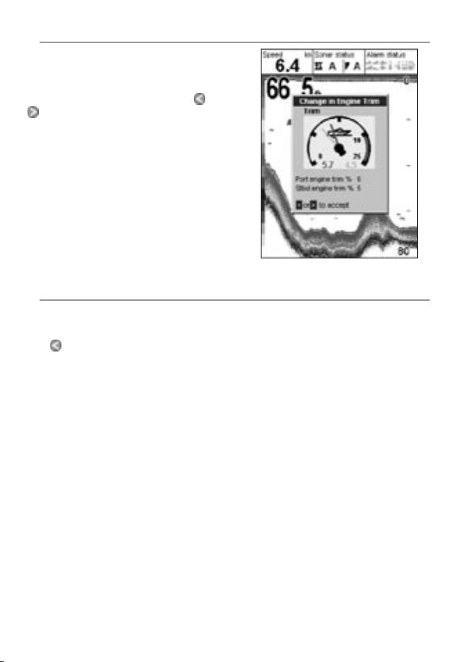
3-4 Trim indic ator
When the engine trim is adjusted, a trim popup
window can show the new trim angle. To see
this window or not, set Trim popup to On or Off
(see section 3-7). The window will automatically
disappear after two seconds, or else press
to make the window disappear.
Before use, calibrate trim (see section 3-8-2).
or
3-5 Engine fault alarms
There are many Smar tCraft engine fault alarms.
These alarms operate just like the other alarms in
the Navman instrument; when the alarm sounds,
press
to mute the alarm:
Low reserve oil.
Low remote oil.
RPM over speed.
Low oil pressure.
High engine volt age.
Low engine voltag e.
A Navman instrument’s low bat tery alarm
measures the voltage the instrument; the
above two alarms measure the voltage at the
engine.
Low bloc k (water) pressure.
Engine overheat.
Low drive lu be.
(MerCrusier stern drive only).
Water in fuel.
Engine G uardianTM active : The Engine
Guardian has detected a fault. The fault is
displayed with the alarm.
Engine c ommunicatio n lost: The
Navman instrument can not receive
engine data from the SmartCraft gateway.
Check engine: There are many other
engine fault alarms. When one of these
alarms sounds, the alarm Check engine is
displayed. For more information about the
alarm, display the list of active alarms or the
alarm histor y (see section 3- 6).
Notes:
1 For help when an Smar tCraft alarm occurs,
contact your Mercury dealer.
2 These SmartCraft alarms are always on. The
alarm values are determined by the engine
type.
3 A list of active faults and a fault histor y can be
displayed (see section 3-6).
NAVMAN SmartCraft Gateways Installation and Operation Manual12
Page 13
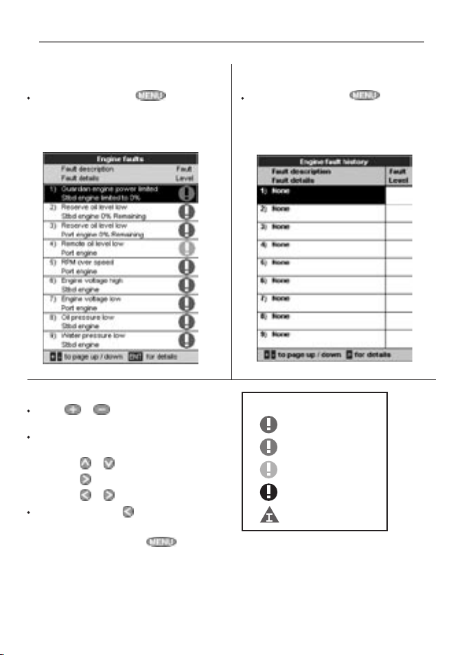
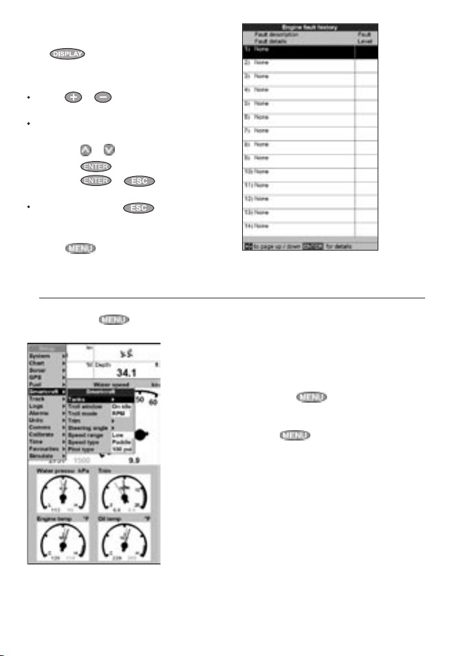
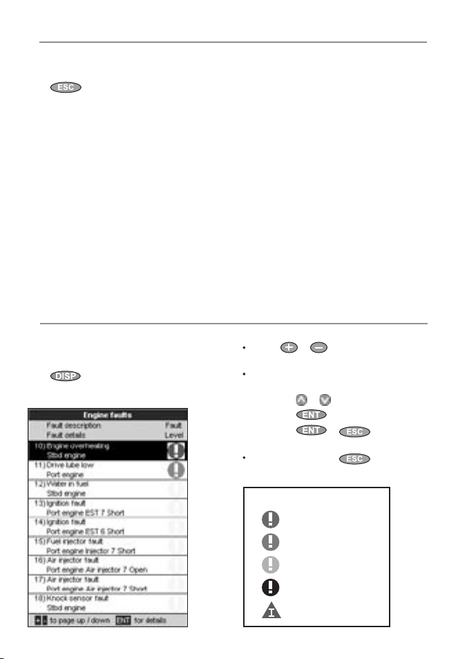
3-6 Engine fault lis ts
There are two lists of Smar tCraft engine faults:
1 Engine faults list
A list of active engine fault alarms.
To display the list, press until
the Setup menu is displayed, select
Smar tCraft, then selec t Engine
faults.
2 Engine faults history
A list of nine recent engine fault alarms.
To display the list, press until
the Setup menu is displayed, select
Smar tCraft, then selec t Engine fault
history
.
When a fau lts list or his tory is disp layed
Press
or to page up and down the
list.
To display more information about a
particular fault:
i Press
ii Press
iii Press
To exit the list, press
To clear the engine fault history:
1 From a main display, press
Setup menu is displayed.
2 Select SmartCraft, then select Reset
fault history
or to select the fault.
to display the information.
or to return to the list.
.
until the
.
Each engine fault has a priority:
Red: Critical
Orange: Severe
Yellow: Warning
Black: Caution
Information
13NAVMAN SmartCraft Gateways Installation and Operation Manual
Page 14

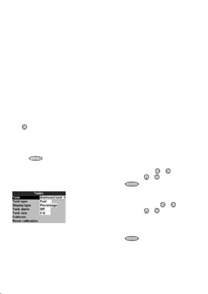
3-7 SmartCraf t setup data
To go to the SmartCraft setup data, press
until the Setup menu is displayed, then select
Smar tCraft. The setup options are:
Engine faults, Engine fault history, Reset fault
history
See section 3-6.
Troll wind ow
Select from a menu:
On idle: Troll window is displayed when
you press and the throttle is at idle
and the engine is in gear.
Always: Troll window is displayed when you
press
Never: Troll window never displayed, troll
control is not available.
Troll mode
Press to select what troll mode controls:
RPM: Controls engine idle RPM.
Speed : Controls engine idle RPM to try to
achieve the desired boat speed.
See section 3-3, notes 1 and 2
Trim popup
Press to select:
Off: Trim popup window is never displayed.
On: Trim popup window is displayed when
trim is changed.
Trim popup f ilter
This filter can stop the trim popup window
appearing because of engine vibration rather
than a trim change.
Press
then press
Select Off or a low value first. Run the boat
at a range of speeds and increase the value if
vibration causes the trim popup window to
appear. If the value is high, the trim window will
appear slowly when trim changes.
Speed ra nge
Set the speed range for an analog speed gauge
(see Gauge ty pe below). The options are
High, Medium and Low. A higher range displays
a higher maximum speed but the display is more
compressed.
.
, then press or to select a value,
. The values are Off and 1 to 5.
NAVMAN SmartCraft Gateways Installation and Operation Manual14
Speed t ype
Press to select the source of the water (boat)
speed reading:
Pitot: The engine’s pitot sensor.
Paddle: A Navman paddlewheel sensor.
The pitot sensor is more accurate at high speeds
but is not accurate at low speeds. The paddle
wheel sensor is more accurate at low speeds.
To use troll speed control, set Speed typ e to
Paddle
.
Pitot ty pe
Press to select 100 psi or 200psi to match
the pitot type installed on the boat.
Gauge t ype
Press to select the type of gauges in the Small,
Medium and Large SmartCraft displays (see
section 3-2):
Analogue: Dial displays (see also Spee d
range above).
Digital: Number displays.
Page 15

Gauge se tup
Select what data is displayed in the gauges on
the three Smar tCraft gauge displays. Note that
the factory default has gauges appropriate to the
type of engine.
1 To select a gauge display. Press
the display name (Small, Medium, Large or
Tanks) turns blue.
2 Press
3 Change the gauge:
4 Repeat steps 1 to 3 to change more gauges,
or to select a gauge.
i Press
ii Press
then press
the main display.
to display a menu of options for
the selec ted gauge (see right; the options
available will depend on your engine, see
section 1-1).
or to select an option, then
.
press
one or more times to return to
or until
Header s etup
Select what data is displayed in the header data
on the four Smar tCraft displays. The display
shows the header, with the selec ted data item
highlit.
1 Press or to select the header item to
change.
2 Change the item:
i Press
ii Press
3 Repeat steps 1 and 2 to change more header
items, then press one or more times to
return to the main display.
to display a menu of options for
the selec ted item (see right; the options
available will depend on your engine, see
section 1-1).
or to select an option, then
.
press
15NAVMAN SmartCraft Gateways Installation and Operation Manual
Page 16

3-8 Smart Craft calibration
There are three SmartCraft calibrations.
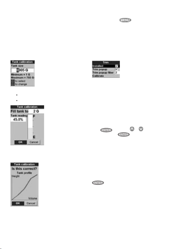
3-8-1 Tanks calibration
If tanks have level sensors fitted (see section
1-1-1), set the type of tank, the tank alarms and
calibrate if required:
Press
displayed, then select Calibrate, then
select Tanks.
For each tank with a level sensor, follow the
steps below:
1 Select
from the menu.
2 Select
tank type from the menu (Unused, Fuel,
Water
3 The raw level sensor data is the level in the
tank as a percentage of the level when the
tank is full (100 %). To select how the level
sensor data is displayed on the
display (see section 3-2), select Display
type, press and selec t the type from the
menu:
Percentage: Display the raw level
If the sides of the tank are not vertical
until the Setup menu is
Tank, press and select the tank
Tank type, press and select the
, Oil or Waste).
Tanks
sensor data. Note:
and straight, then the Percentage
level sensor data displayed does not
NAVMAN SmartCraft Gateways Installation and Operation Manual16
correspond to the volume in the tank; for
example if the sensor shows 50 %, the
tank is not 50 % full.
For Percentage display type, fuel Used
and Rem aining on the Fuel display can
not be calculated, and are displayed as
Invalid
.
Volume: Display a volume calculated linearly
from the sensor data, for example if Tank
size (see below) is 500 G and the sensor
shows 50 % of full, then 250 G is displayed.
Choose this option only if the tank has
vertical, straight sides and the tank bottom
and top are flat.
Calibrated volume : Display a volume
calculated non linearly from the sensor data.
Choose this option if the tank does not have
vertical, straight sides. You must calibrate the
tank (see step 6 below).
4 To set a low level alarm for the tank (see
section 3-2):
i Select Tank alarm
ii Press
iii Press
iv Finally, press
5 Set the tank size:
i Select Tank size
ii Press
iii Finally, press
6 If Display type is Calibrated
volume, the sensor data must be calibrated.
i Select Calibrate
ii Follow the instruc tions displayed to add
iii Finally, the display shows Tank size
to turn the alarm On or Off.
or to set the alarm value. The
alarm will sound if the alarm is On and
the tank level is less than the alarm value.
or to set the tank size.
measured amounts of fuel.
(set in step 5 above), Actual size (the
volume of fuel you added to the tank),
and asks Is th is correct? Select:
Accept to accept the calibration
Chang e to change Tank size if
Tank size is not the same as Actual
.
size
.
.
.
.
.
Page 17

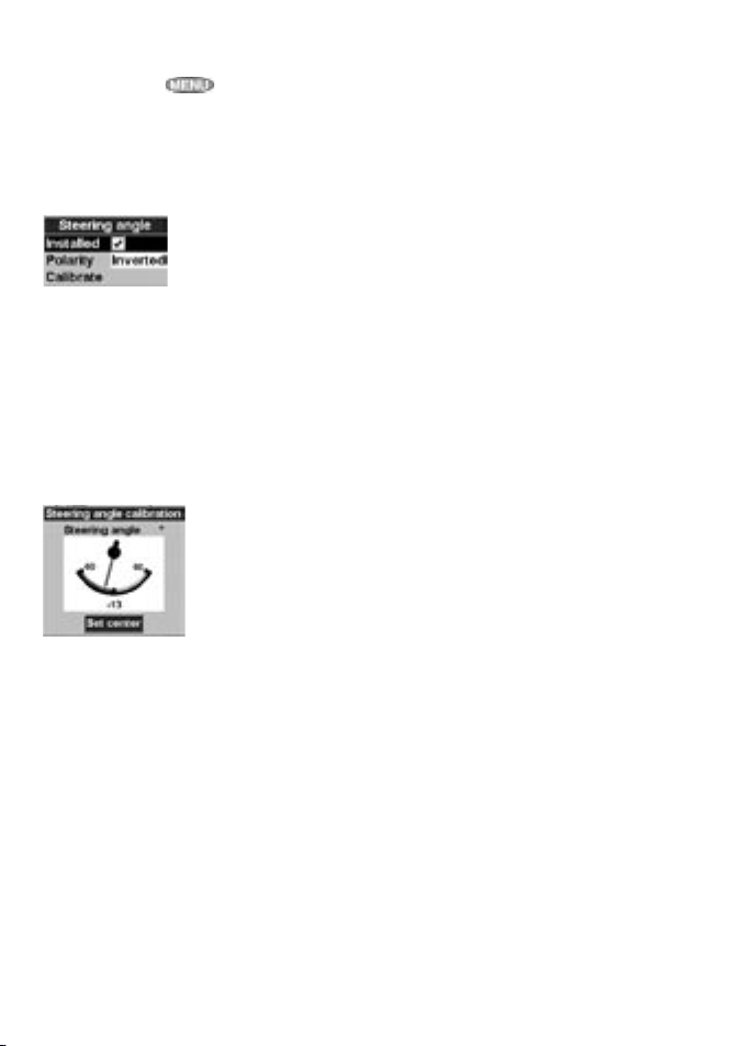
3-8-2 Trim calibration
If the SmartCraft system has trim control, calibrate
the trim angle display (see section 3- 4):
1 Press
displayed, then select Calibrate, then
select Trim
2 Select Inst alled and press
Yes.
3 Select Ca librate. Follow the instructions
displayed.
until the Setup menu is
.
to select
3-8-3 Steering angle calibration
If the SmartCraft system has a steering angle
sensor, it must be calibrated.
1 There must be little wind and little current.
Travel at a typical cruising speed.
2 Press
displayed, select Calibrate
Steering angle
until the Setup menu is
, then selec t
.
3 Steer the boat to por t. If the display needle
does not turn to port, select Polarity
and press
(Normal or Inverted).
4 Steer in a straight line, then select Set
center to calibrate the steering angle.
to select the other polarity
17NAVMAN SmartCraft Gateways Installation and Operation Manual
Page 18

4 Operation with a Navman TRACKFISH 6600
Before a SmartCraft gateway is connec ted, the TR ACKFISH 6600 functions normally, with no SmartCraf t
functions. When a Smar tCraft gateway is connected and SmartCraft is turned On (see section 4-1),
SmartCraft functions become available and some standard func tions change.
SmartCraft functions
Data displays
Engine performance and tank level displays ......................................................................................See section 4-2
Troll control
Automatically maintains a set engine idle RPM or idle boat speed ........................................... See section 4-3
Trim indicator
Displays the trim angle when engine trim is adjusted .................................................................... See section 4-4
Alarms
Engine fault alarms ....................................................................................................................................... See section 4-5
Engine fault list, a list of active SmartCraft engine fault alarms ...................................................See section 4-6
Engine fault history, a list of past SmartCraft engine fault alarms ..............................................See section 4-6
Tank low level alarms ...............................................................................................................................See section 4-2-1
Setup dat a and calibrations
SmartCraft setup data ..............................................................................................................See sections 4-1 and 4-2
SmartCraft calibrations, Tanks, Trim and Steering angle ................................................................. See section 4-7
SmartCraft setup data and calibrations ..............................................................................See sections 4-7 and 4-1
The SmartCraft data available depends on the engine type and the sensors fitted (see section 1-1).
Changes to s tandard func tions with Smart Craft enabled :
If there are no optional level sensor(s) fitted to the fuel tanks (see section 1-1-1), then the
If each fuel tank has an optional level sensor fitted (see section 1-1-1), then these tank levels are
For more information, see the TRACKFISH 6600 Installation and Operation manual.
key: When using troll control, pressing can display the troll window. Press
a second time to display the normal menu.
Fuel: The fuel display functions normally but with fuel and speed data coming from the SmartCraft
system rather than from separate sensors connected to the TRACKFISH 6600.
Smartcraft fuel flow is used to calculate fuel remaining. The fuel setup data is the same as the
standard TRACKFISH 6600. You must tell the TRACKFISH 6600 when you add or remove fuel (see
the TRACKFISH 6600 Installation and Operation manual).
used to calculate fuel remaining. In the Fuel display, Used changes to Trip used, and the only fuel
setup option is Clear trip used. Trip used measures the volume of fuel used until it is reset to zero
by selecting Clear trip used in the fuel setup menu. You do not tell the TRACKFISH 6600 when you
add or remove fuel.
Engine hours: Engine hours on the Log display come from the SmartCraft system.
It can not be reset.
Simulate mode: Data from the SmartCraft engine(s) and sensors is simulated. The SmartCraft data
simulated will probably differ from the data available in your system.
NAVMAN SmartCraft Gateways Installation and Operation Manual18
Page 19

4-1 Setting up t he TRACKFISH 6600 for Smar tcraft
There are two SmartCraft items in the TRACKFISH
6600 System setup menu. To display the System
menu, press until the Setup menu is
displayed, then select System.
Sonar
Select: For normal sonar operation
De-select: To disable
sonar functions. For
instrument’s SmartCraft functions
only,
the sonar transducer and
use with the
Smart Craft
Select: Normal SmartCraft operation
De-select: SmartCraft functions. The instrument
will now use any Navman fuel
sensors which are connected.
Note:
SmartCraft utilises NavBus comms. NavBus will
turn on if SmartCraft is turned on.
4-2 SmartCraft eng ine data displays
There are four SmartCraft engine displays, shown below.
Note: If the boat has twin engines, two needles will appear on most of the gauge displays. The red
needle or number shows port engine data, green shows starboard engine data.
Data heade r display area
Engine dat a display area
Small : Eight small
gauges
Diagno stics: Shows
eight small gauges.
Press , select
SmartCraft, then select
Diagnostics.
Medium: Two medium,
four small gauges
Cruising: Shows two
large and four small
gauges. Press
, select SmartCraft,
then selec t Cruising.
Large : Two large gauges Tanks: Tank levels
Engine d ata large:
Shows two large
gauges. To display this,
press
SmartCraft, then select
Engine data large.
, select
Tank status : Shows
the levels in the tanks.
To display this, press
, select
SmartCraft, then
select Tank status.
19NAVMAN SmartCraft Gateways Installation and Operation Manual
Page 20

4-2-1 Tank status display
The tank level display shows the levels from the
optional level sensors in one or two tank s per
engine (see section 1-1-1).
Before use, each tank must be set up and
calibrated (see section 4-7-1).
An alarm can be set to sound if the level in a tank
is low (see sec tion 4-7-1). These alarms are in
addition to any SmartCraft engine fault low level
alarms (see section 4-5).
4-2-2 Customising the engine dat a displays
To customise an engine data display, press
, select SmartCraft, select the display
to customise, and press
display the options:
Data set up
Select the data item to be displayed in the data
header display area (at the top of the display):
1 Press , , or to select the data item
to change.
2 Select the item by pressing
display a menu of options for the selected
item (the options available will depend on
your engine, see section 1-1).
or to select an option, then press
Press
3 Repeat steps 1 and 2 to change more data
.
items, then press
main display.
. Press to
. this will
to return to the
Gauge se tup
Select the data to be displayed in the engine data
display areas (not for Tank status display).
1 Press
2 Change the gauge:
3 Repeat steps 1 to 2 to change more gauges,
, , or to select a gauge to
change.
i Press
options for the selected gauge (see right;
the options available will depend on your
engine, see section 1-1).
ii Press
press .
then press
display.
to display a menu of
or to select an option, then
to return to the main
Gauge t ype
Select the type of gauges to be displayed (not for
Tank status display):
Analogue: Dial type displays (see also
section 4-7: Speed range).
Digital: Number type displays.
Notes:
1 The factory default has gauges appropriate to
the type of engine.
2 To further customise the three gauge
displays, change Speed range
type and Pitot type (see section 4-7).
, Speed
NAVMAN SmartCraft Gateways Installation and Operation Manual20
Page 21

4-3 Troll control
Troll control allows adjustment of the engine’s
idle speed from the Navman instrument. Troll
control automatically controls the engine idle
speed to maintain a set engine RPM or boat
speed.
To use troll control, set Troll window to On idle
or Always and set Troll mode to Speed or R PM
(see section 4-7).
To use speed troll mode, set Spe ed typ e to
Paddle (see section 4 -7).
To prohibit troll control, set Troll window to
Never (see section 4-7).
Engagi ng troll contr ol
1 Set the throttle(s) to idle and the engine(s)
in gear. From a main display, press
display the Troll control window (see right).
2 Press
3 Press
or to set the desired RPM or boat
speed (see notes 1 and 2).
TRACKFISH 660 0 automatically controls RPM
or speed. Or, press
control disengaged.
to engage troll control. The
to leave troll
to
Changi ng RPM or speed whi le troll contr ol
engage d
1 From a main display, press to display
the troll window.
2 Press
3 Press
or to change the desired RPM or
boat speed (see notes 1 and 2).
Diseng aging troll c ontrol
Either move the throttle from idle, or:
1 From a main display, press
the troll window. Press
(Disengage) and press
2 Or, press to leave troll control
engaged.
to display
or to select Off
4-4 Trim ind icator
When the optional engine trim is adjusted, a trim
popup window can show the new trim angle.
To see this window or not, set Trim popup to On
or Off (see section 4-7: Trim). The window will
Notes:
1 The Troll range of engine idle RPM
adjustment available for both RPM and speed
mode depends on engine t ype. Generally this
is between 600 and 1000 RPM.
2 In speed troll control, the boat might not
reach the desired speed if the maximum
RPM available for troll control is too low or if
conditions are bad.
3 Troll can not engage unless engine throttle(s)
are in idle, and engine(s) are in gear.
4 Troll control is not available on some
MerCrusier
5 To use speed troll control, the Navman
instrument must have a Navman
paddlewheel speed sensor connected.
automatically disappear af ter two seconds, or else
press
Before use, calibrate trim (see section 4-7: Trim).
TM
engines.
to close the window.
21NAVMAN SmartCraft Gateways Installation and Operation Manual
Page 22
4-5 Engine f ault alarms
There are many Smar tCraft engine fault alarms.
These alarms operate just like the other alarms in
the Navman instrument; when the alarm sounds,
press
Low reserve oil.
Low remote oil.
RPM over speed.
Low oil pressure.
High engine volt age.
Low engine voltag e.
A Navman instrument’s low bat tery alarm
Low bloc k (water) pressure.
Engine overheat.
Low drive lu be: (MerCrusier stern drive
Water in fuel.
to mute the alarm:
measures the voltage at the instrument; the
above two alarms measure the voltage at the
engine.
only).
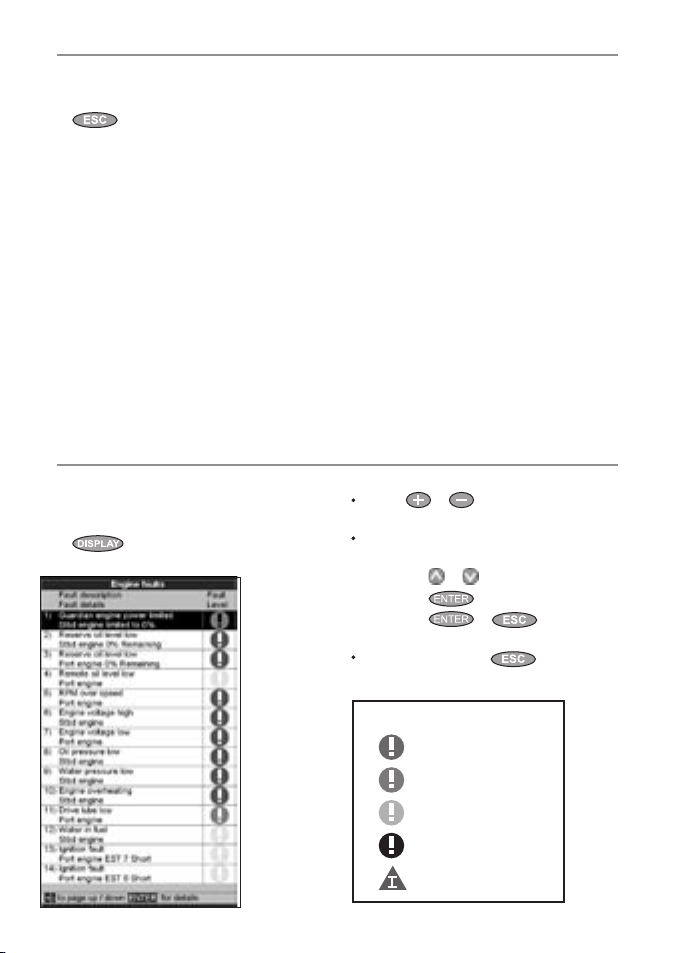
4-6 Engine fault lists
There are two lists of Smar tCraft engine faults:
4-6-1 Engi ne faults lis t
To display a list of active engine fault alarms:
press
Engine faults
, select SmartCraft, then select
.
Engine G uardianTM active : The Engine
Guardian has detected a fault. The fault is
displayed with the alarm.
Engine c ommunicatio n lost: The Navman
instrument can not receive engine data from
the SmartCraft gateway.
Check engine: There are many other
engine fault alarms. When one of these
alarms sounds, the alarm Check engine is
displayed. For more information about the
alarm, display the list of active alarms or the
alarm histor y (see section 4- 6).
Notes:
1 For help when an Smar tCraft alarm occurs,
contact your Mercury dealer.
2 These SmartCraft alarms are always on. The
alarm values are determined by the engine
type.
3 A list of active faults and a fault histor y can be
displayed (see section 4-6).
When the f aults list is d isplayed
Press
or to page up and down the
list.
To display more information about a
particular fault:
i Press
ii Press
iii Press
To exit the list, press
or to select the fault.
to display the information.
or to return to the
list.
.
Each engine fault has a priority:
Orange: Severe
Yellow: Warning
Black: Caution
Information
NAVMAN SmartCraft Gateways Installation and Operation Manual22
Red: Critical
Page 23
4-6-2 Eng ine fault hist ory
To display a list of recent engine fault alarms,
press , select Smar tCraft, then selec t
Engine fault history
When the En gine fault hi story is disp layed
Press
or to page up and down the
list.
To display more information about a
particular fault:
i Press
ii Press
iii Press
To exit the list, press
To clear the engine fault history:
Go to the engine fault histor y display,
press
history.
or to select the fault.
list.
and selec t Reset fault
.
to display the information.
or to return to the
.
4-7 SmartCraft setup data and c alibrations
To go to the SmartCraft setup data and
calibrations, press
displayed, then select SmartCraft
Note:
If there is more than one SmartCraft capable
Navman instrument in a system, some setup data
may be different in each instrument.
until the Setup menu is
.
The setup and calibration options are:
Tanks
Set up and calibrate the tanks (see section 4-7-1).
Troll wind ow
Select from a menu:
On idle: Troll window is displayed when
you press
and the engine is in gear.
Always: Troll window is displayed when you
press .
Never: Troll window never displayed, troll
control is not available.
and the throttle is at idle
Troll mode
Select what troll mode controls:
RPM: Controls engine idle RPM.
Speed : Controls engine idle RPM to try to
achieve the desired boat speed.
See section 4-3, notes 1 and 2
Trim
Set up and calibrate the trim display (see sec tion
4-7-2).
23NAVMAN SmartCraft Gateways Installation and Operation Manual
Page 24
Steerin g angle
Set up and calibrate the steering angle (see
section 4-7-3).
Speed ra nge
Set the speed range for an analog speed gauge.
The options are High
higher range displays a higher maximum speed
but the display is more compressed.
, Mediu m and Low. A
Speed t ype
Select the source of the water (boat) speed
reading:
Pitot: The engine’s pitot sensor.
Paddle: A Navman paddlewheel sensor.
The pitot sensor is more accurate at high
speeds but is not accurate at low speeds. The
paddlewheel sensor is more accurate at low
speeds. To use troll speed control, set Spee d
type to Pad dle
.
Pitot ty pe
Press to select 100 psi or 200psi to match
the pitot type installed on the boat.
4-7-1 Tanks setup and calibration
Set up and calibrate tanks with level sensors
fitted (see section 1-1-1):
1 Press
displayed, select Sm artCraft, then select
Tanks
2 For each tank in the boat, selec t Tank, select
the tank to set up, then set up and calibrate
the tank.
Note:
The displayed Tank size unit uses the set ting
selected in the Navman instrument. To change to
a different unit type, use the Setup > Units menu
in the Navman instrument.
For each tank, the options are:
until the Setup menu is
.
Tank type
Select the tank type (Unused, F uel, Water,
Oil or Waste).
Displ ay type
The data from the level sensor in each tank is the
depth in the tank as a percentage of the depth
when the tank is f ull. If the sides of the tank are
not vertical and straight, or if the tank top and
bottom are not flat, then the level sensor data
does not correspond to the volume in the tank;
for example if the sensor shows 50 %, the tank is
not 50 % full.
The Display typ e option selects how the
level sensor data is displayed:
Percentage: Display the percentage level
sensor data. The default is the percentage
level sensor data. If the tank is calibrated, then
a calibrated percentage is displayed.
Volume: Display a volume calculated
from the sensor data. The default is a linear
calculation, for example if the tank holds 500
G and the sensor shows 50 % of full, then 250
G is displayed. This is correct if the sides of the
tank are vertical and straight and the tank top
and bottom are flat. If this is not so, calibrate
the tank (see C alibrate below).
Tank size
Set the tank size:
i Set the tank size: press
digit, then press
ii Press
.
or to select a
or to change the digit.
Tank alarm
To set a low level alarm for the tank:
i Set the alarm value: press
digit, then press
To turn the alarm of f, set the alarm value to
0. If the alarm value is greater than zero, the
alarm will sound if the tank level is less than
the alarm value.
ii Press
.
or to select a
or to change the digit.
Calib rate
Calibrate the tank readings if the sides of the tank
are not vertical and straight, or if the tank top
and bottom are not flat. The following procedure
requires the tank to be filled from empty. The
NAVMAN SmartCraft Gateways Installation and Operation Manual24
Page 25
Tank Calibration screen will display an amount of
fuel to add to the tank - select OK each time the
measured amount is added. This will happen a
number of times.
i Enter the tank size (volume).
ii Follow the on-screen instructions displayed
to add measured amounts of fuel. Select OK
each time the measured amount is added.
iii The display shows Tank calibration
- Tank profile and asks Is th is
correct?
Select:
iv If the actual tank size did not match that in
step (i), then change the tank size from
the menu.
.
OK
to accept the calibration
Cancel
to cancel.
4-7-2 Trim setup and calibration
Set up and calibrate a SmartCraft trim control (see
section 4-4). Press
is displayed, then select SmartCraft, then
select Trim. The options are:
Installed
Select: Trim sensors are installed in the
engine(s).
De-select: No trim sensors installed in the
engine(s).
until the Setup menu
Trim popup
Select: Trim sensors are installed in the
engine(s).
De-select: Trim popup window is never
displayed.
Trim popup f ilter
This filter can stop the trim popup window
appearing because of engine vibration rather
than a trim change.
Press
value, then press
and 1 to 5.
Select Off or a low value first. Run the boat
at a range of speeds and increase the value if
vibration causes the trim popup window to
appear. If the value is high, the trim window will
appear slowly when trim changes.
, then press or to select a
. The values are Off
Calibrate
Follow the on-screen instructions displayed to
calibrate the displayed trim angle, and press
as required.
Reset calibration
Reset the tank calibration to the default - the
displayed volume is calculated linearly from the
sensor data (see Display type above). Any tank
calibration data will be lost.
25NAVMAN SmartCraft Gateways Installation and Operation Manual
Page 26
4-7-3 Steering angle setup and calibration
Set up and calibrate the SmartCraft steering
angle display. Press until the Setup menu
is displayed, then select SmartCraft, then
select Steering angle. The options are:
Installed
Select: Steering angle sensor installed.
De-select: No steering angle sensor installed.
Polarit y
Steer the boat to port. If the steering angle
pointer does not move to port, choose the other
polarit y (Normal or Inver ted).
Calib rate
1 There must be little wind and little current.
Travel at a typical cruising speed.
2 Steer in a straight line, then select
Calibrate to calibrate the steering angle.
3 Press enter when steering in a straight line.
NAVMAN SmartCraft Gateways Installation and Operation Manual26
Page 27

5 Operation with a Navman FISH 4600
Before a SmartCraft gateway is connec ted, the FISH 4600 functions normally, with no SmartCraft
functions. When a Smar tCraft gateway is connected and SmartCraft is turned On (see section 5-1),
SmartCraft functions become available and some standard func tions change.
SmartCraft functions
Data displays
Engine performance and tank level displays .....................................................................................See section 5-2
Troll control
Automatically maintains a set engine idle RPM or idle boat speed .......................................... See section 5-3
Trim indicator
Displays the trim angle when engine trim is adjusted ................................................................... See section 5-4
Alarms
SmartCraft engine fault alarms ............................................................................................................... See section 5-5
Engine fault list, a list of active SmartCraft engine fault alarms ..................................................See section 5-6
Engine fault history, a list of past SmartCraft engine fault alarms ............................................. See section 5-6
Tank low level alarms .............................................................................................................................. See section 5-2-1
Setup data and calibrations
SmartCraft setup data ............................................................................................................. See sections 5-6 and 5-8
SmartCraft calibrations, Tanks, Trim and Steering angle ................................................................ See section 5-7
SmartCraft setup data and calibrations ............................................................................. See sections 5-7 and 5-1
The SmartCraft data available depends on the engine type and the sensors fitted (see section 1-1)
Changes to s tandard func tions with Smart Craft enabled :
If there are no optional level sensor(s) fitted to the fuel tanks (see section 1-1-1), then the Smar tcraft
If each fuel tank has an optional level sensor fitted (see section 1-1-1), then these tank levels are used
For more information, see the FISH 4500/4600 I nstallation and Ope ration manual.
key: When using troll control, pressing can display the troll window. Press a
second time to display the normal menu.
Fuel: The fuel display functions normally but with fuel and speed data coming from the SmartCraf t
system rather than from separate sensors connected to the FISH 4600.
fuel flow is used to calculate fuel remaining. The fuel setup data is the same as the standard FISH
4600. You must tell the FISH 4600 when you add or remove fuel (see the FISH 4500/4600 I nstallation
and Operati on manual).
to calculate fuel remaining. In the Fuel display, Used changes to Trip used, and the only fuel
setup option is Clear trip used
to zero by selecting Clear trip used in the fuel setup menu. You do not tell the FISH 4600
when you add or remove fuel.
Engine h ours: Engine hours on the Log display come from the Smar tCraft system.
It can not be reset.
Simulate mode: Data from the SmartCraf t engine(s) and sensors is simulated. The SmartCraft data
simulated will probably dif fer from the data available in your system.
. Trip used measures the volume of fuel used until it is reset
.
27NAVMAN SmartCraft Gateways Installation and Operation Manual
Page 28

5-1 Setting up the FISH 4600 for Smartcraft
There are two SmartCraft items in the FISH 4600
System setup menu. To display the System menu,
press
then selec t System
until the Setup menu is displayed,
.
Sonar
Select: For normal sonar operation
De-select: To disable the sonar transducer and
sonar func tions. For use with the
instrument’s SmartCraft functions
only,
Smart Craft
Select: Normal SmartCraft operation
De-select: SmartCraft functions. The
instrument will now use any
Navman fuel sensors which are
connected.
Note:
SmartCraft utilises NavBus comms. NavBus will
turn on if Smar tCraft is turned on.
5-2 SmartCraft engine data dis plays
There are four SmartCraft engine displays, shown below.
Note: If the boat has twin engines, two needles will appear on most of the gauge displays. The red
needle or number shows port engine data, green shows starboard engine data.
Engine dat a display area
Data heade r display area
Small : Eight small
gauges
Shows eight small
gauges. Press
, select SmartCraft,
then selec t Small.
Medium: Two medium,
four small gauges
Shows two large and
four small gauges.
Press
Smar tCraft, then
select Mediu m.
NAVMAN SmartCraft Gateways Installation and Operation Manual28
, select
Large : Two large
gauges
Shows two large
gauges. To display this,
press , select
Smar tCraft, then
select Large.
Tanks: Tank levels
Shows the levels in the
tanks. To display this,
press
Smar tCraft, then
select Tanks.
, select
Page 29
5-2-1 Tank status display
The tank level display shows the levels from the
optional level sensors in one or two tank s per
engine (see section 1-1-1).
Before use, each tank must be set up and
calibrated (see section 5-7-1).
An alarm can be set to sound if the level in a tank
is low (see sec tion 5-7-1). These alarms are in
addition to any SmartCraft engine fault low level
alarms (see section 5-5).
5-2-2 Customi sing the engine dat a displays
To customise an engine data display, press
, select SmartCraft, select the display
to customise. Press
available options; Gauge t ype, Gauge setup, and
Header setup, then press
to display the
.
Gauge ty pe
Select the type of gauges to be displayed (not for
Tank status display):
Analogue: Dial type displays (see also
section 5-7: Speed range).
Digital: Number type displays.
Notes:
1 The factory default has gauges appropriate to
the type of engine.
2 To further customise the three gauge
displays, change
type
Speed range, Speed
and Pitot type (see section 5-7)
Gauge setup
Select the data to be displayed in the engine data
display areas (not for Tank status display).
1 Press
2 Change the gauge:
, , or to select a gauge to
change.
i Press
options for the selected gauge (see
above; the options available will depend
on your engine, see section 1-1).
to display a menu of
ii Press or to select an option, then
press
3 Repeat steps 1 to 2 to change more gauges,
then press
display.
.
to return to the main
Header s etup
Select the data item to be displayed in the data
header display area (at the top of the display):
1 Press
2 Select the item by pressing
Press or to select an option, then press
3 Repeat steps 1 and 2 to change more data
, , or to select the data item
to change.
display a menu of options for the selected
item (the options available will depend on
your engine, see section 1-1).
.
items, then press
main display.
. this will
to return to the
29NAVMAN SmartCraft Gateways Installation and Operation Manual
Page 30
5-3 Troll control
Troll control allows adjustment of the engine’s
idle speed from the Navman instrument. Troll
control automatically controls the engine idle
speed to maintain a set engine RPM or boat
speed.
To use troll control, set Troll window to On idle
or Always and set Troll mode to Speed or R PM
(see section 5-7).
To use speed troll mode, set Spe ed typ e to
Paddle (see section 5-7).
To prohibit troll control, set Troll window to
Never (see section 5-7).
Engagi ng troll contr ol
1 Set the throttle(s) to idle and the engine(s)
in gear. From a main display, press
display the Troll control window (see right).
2 Press
3 Press
or to set the desired RPM or boat
speed (see notes 1 and 2).
to engage troll control. The
FISH 4600 automatically controls RPM or
speed. Or, press to leave troll control
disengaged.
Changi ng RPM or speed whi le troll contr ol
engage d
1 From a main display, press to display
the troll window.
2 Press or to change the desired RPM or
boat speed (see notes 1 and 2).
3 Press
Diseng aging troll c ontrol
Either move the throttle from idle, or:
1 From a main display, press
the troll window. Press
(Disengage) and press
2 Or, press to leave troll control
engaged.
or to select Off
to
to display
Notes:
1 The Troll range of engine idle RPM
adjustment available for both RPM and speed
mode depends on engine t ype. Generally this
is between 600 and 1000 RPM.
2 In speed troll control, the boat might not
reach the desired speed if the maximum
RPM available for troll control is too low or if
conditions are bad.
3 Troll can not engage unless engine throttle(s)
are in idle, and engine(s) are in gear.
4 Troll control is not available on some
MerCrusier
5 To use speed troll control, the Navman
instrument must have a Navman
paddlewheel speed sensor connected.
TM
engines.
5-4 Trim indicator
When the optional engine trim is adjusted, a trim
popup window can show the new trim angle.
To see this window or not, set Trim popup to On
or Off (see section 5-7: Trim). The window will
NAVMAN SmartCraft Gateways Installation and Operation Manual30
automatically disappear af ter two seconds, or else
press
Before use, calibrate trim (see section 5-7: Trim).
to close the window.
Page 31
5-5 Engine fault alarms
There are many Smar tCraft engine fault alarms.
These alarms operate just like the other alarms in
the Navman instrument; when the alarm sounds,
press to mute the alarm:
Low reserve oil.
Low remote oil.
RPM over speed.
Low oil pressure.
High engine volt age.
Low engine voltag e.
A Navman instrument’s low bat tery alarm
measures the voltage at the instrument; the
above two alarms measure the voltage at the
engine.
Low bloc k (water) pressure.
Engine overheat.
Low drive lu be (MerCrusier stern drive only).
Water in fuel.
5-6 Engine fault lists
There are two lists of Smar tCraft engine faults:
5-6-1 Engin e faults list
To display a list of active engine fault alarms:
press
Engine faults
, select SmartCraft, then select
.
Engine G uardianTM active : The Engine
Guardian has detected a fault. The fault is
displayed with the alarm.
Engine c ommunicatio n lost: The Navman
instrument can not receive engine data from
the SmartCraft gateway.
Check engine: There are many other
engine fault alarms. When one of these
alarms sounds, the alarm Check engine is
displayed. For more information about the
alarm, display the list of active alarms or the
alarm histor y (see section 5- 6).
Notes:
1 For help when an Smar tCraft alarm occurs,
contact your Mercury dealer.
2 These SmartCraft alarms are always on. The
alarm values are determined by the engine
type.
3 A list of active faults and a fault histor y can be
displayed (see section 5-6).
When the f aults list is d isplayed
Press
or to page up and down the
list.
To display more information about a
particular fault:
i Press
ii Press
iii Press
To exit the list, press
or to select the fault.
to display the information.
or to return to the
list.
.
Each engine fault has a priority:
Orange: Severe
Yellow: Warning
Black: Caution
Information
Red: Critical
31NAVMAN SmartCraft Gateways Installation and Operation Manual
Page 32

5-6-2 Engi ne fault histo ry
To display a list of recent engine fault alarms,
press , select Smar tCraft, then selec t
Engine fault history
When the En gine fault hi story is disp layed
Press
or to page up and down the
list.
To display more information about a
particular fault:
i Press
ii Press
iii Press
To exit the list, press
or to select the fault.
list.
.
to display the information.
or to return to the
.
To clear the e ngine fault hi story:
Go to the engine fault histor y display,
press
history
and selec t Reset fault
.
5-7 SmartCraft setup data and calibrations
To go to the SmartCraft setup data and
calibrations, press until the Setup menu is
displayed, then select SmartCraft
Note:
If there is more than one SmartCraft capable
Navman instrument in a system, some setup data
may be different in each instrument.
.
NAVMAN SmartCraft Gateways Installation and Operation Manual32
The setup and calibration options are:
Tanks
Set up and calibrate the tanks (see section 5-7-1).
Troll wind ow
Select from a menu:
On idle: Troll window is displayed when
you press
and the engine is in gear.
Always: Troll window is displayed when you
press
Never: Troll window never displayed, troll
control is not available.
and the throttle is at idle
.
Troll mode
Select what troll mode controls:
RPM: Controls engine idle RPM.
Speed : Controls engine idle RPM to try to
achieve the desired boat speed.
See section 5-3, notes 1 and 2
Trim
Set up and calibrate the trim display (see sec tion
5-7-2).
Page 33

Steerin g angle
Set up and calibrate the steering angle (see
section 5-7-3).
Speed ra nge
Set the speed range for an analog speed gauge.
The options are High
higher range displays a higher maximum speed
but the display is more compressed.
, Mediu m and Low. A
Speed t ype
Select the source of the water (boat) speed
reading:
Pitot: The engine’s pitot sensor.
Paddle: A Navman paddlewheel sensor.
The pitot sensor is more accurate at high
speeds but is not accurate at low speeds. The
paddlewheel sensor is more accurate at low
speeds. To use troll speed control, set Spee d
type to Pad dle
.
Pitot ty pe
Press to select 100 psi or 200psi to match
the pitot type installed on the boat.
5-7-1 Tanks setu p and calibra tion
Set up and calibrate tanks with level sensors fitted
(see section 1-1-1):
1 Press
displayed, select Sm artCraft, then select
Tanks
2 For each tank in the boat, selec t Tank, select
the tank to set up, then set up and calibrate
the tank.
Note:
The displayed Tank size unit uses the set ting
selected in the Navman instrument. To change to
a different unit type, use the Setup > Units menu
in the Navman instrument.
For each tank, the options are:
until the Setup menu is
.
Tank type
Select the tank type (Unused, F uel, Water,
Oil or Waste).
Displ ay type
The data from the level sensor in each tank is the
depth in the tank as a percentage of the depth
when the tank is f ull. If the sides of the tank are
not vertical and straight, or if the tank top and
bottom are not flat, then the level sensor data
does not correspond to the volume in the tank;
for example if the sensor shows 50 %, the tank is
not 50 % full.
The Display typ e option selects how the
level sensor data is displayed:
Percentage: Display the percentage level
sensor data. The default is the percentage
level sensor data. If the tank is calibrated, then
a calibrated percentage is displayed.
Volume: Display a volume calculated
from the sensor data. The default is a linear
calculation, for example if the tank holds 500
G and the sensor shows 50 % of full, then 250
G is displayed. This is correct if the sides of the
tank are vertical and straight and the tank top
and bottom are flat. If this is not so, calibrate
the tank (see C alibrate below).
Tank size
Set the tank size:
i Set the tank size: press
digit, then press
ii Press
.
or to select a
or to change the digit.
Tank alarm
To set a low level alarm for the tank:
i Set the alarm value: press
digit, then press
To turn the alarm of f, set the alarm value to
0. If the alarm value is greater than zero, the
alarm will sound if the tank level is less than
the alarm value.
ii Press
.
or to select a
or to change the digit.
33NAVMAN SmartCraft Gateways Installation and Operation Manual
Page 34

Calib rate
Calibrate the tank readings if the sides of the tank
are not vertical and straight, or if the tank top
and bottom are not flat. The following procedure
requires the tank to be filled from empty. The
Tank Calibration screen will display an amount of
fuel to add to the tank - select OK each time the
measured amount is added. This will happen a
number of times.
i Enter the tank size (volume).
ii Follow the on-screen instructions displayed
to add measured amounts of fuel. Select
each time the measured amount is added.
iii The display shows Tank calibration
- Tank profile and asks Is th is
correct?
Select:
iv If the actual tank size did not match that in
step (i), then change the tank size from
the menu.
.
OK
to accept the calibration
Cancel
to cancel.
OK
Reset ca libration
Reset the tank calibration to the default - the
displayed volume is calculated linearly from the
sensor data (see Display type above). Any tank
calibration data will be lost.
5-7-2 Trim setu p and calibra tion
Set up and calibrate a SmartCraft trim control (see
section 5-4). Press
is displayed, then select SmartCraft, then
select Trim. The options are:
until the Setup menu
Instal led
Select: Trim sensors are installed in the
engine(s).
De-select: No trim sensors installed in the
engine(s).
Trim popup
Select: Trim sensors are installed in the
engine(s).
De-select: Trim popup window is never
displayed.
Trim popup f i lter
This filter can stop the trim popup window
appearing because of engine vibration rather
than a trim change.
Press , then press or to select a
value, then press
and
1 to 5.
Select Off or a low value first. Run the boat
at a range of speeds and increase the value if
vibration causes the trim popup window to
appear. If the value is high, the trim window will
appear slowly when trim changes.
. The values are Off
Calib rate
Follow the on-screen instructions displayed to
calibrate the displayed trim angle, and press
as required.
NAVMAN SmartCraft Gateways Installation and Operation Manual34
Page 35

5-7-3 Steering angle setup and calibration
Set up and calibrate the SmartCraft steering
angle display. Press
is displayed, then select SmartCraft, then
select Steering angle. The options are:
until the Setup menu
Installed
Select: Steering angle sensor installed.
De-select: No steering angle sensor installed.
Polarit y
Steer the boat to port. If the steering angle
pointer does not move to port, choose the other
polarit y (Normal or Inver ted).
Calibrate
1 There must be little wind and little current.
Travel at a typical cruising speed.
2 Steer in a straight line, then select Calibrate to
calibrate the steering angle.
3 Press enter when steering in a straight line.
35NAVMAN SmartCraft Gateways Installation and Operation Manual
Page 36

Appendix A - Specifications
Physical
Size 130 x 62 x 26 mm (5.1 x 2.4 x 1.0 in).
Operating temperature 0 to 50°C (32 to
122°F).
Built-in cable to the Navman instrument, 1 m
(3.3 ft) long.
Built-in cable to SmartCraft and engine, 300
mm (1 ft) long.
Electrical
Power supply 9.0 to 30 V DC, 50 mA .
Interfaces
NavBus connection to Navman instruments.
CAN bus connec tion to SmartCraft system.
Standards compliance
EMC compliance
USA (FCC): Par t 15 Class B.
Europe (CE): EN50081-1,EN50082-1,
EN55024, EN55022, ISO7637-1.
New Zeal and and Australi a (C Tick) :
AS-NZS 3548.
Appendix B - Troubleshooting
1 No SmartCraft functions available or
SmartCraft data is zero or is not displayed
a Boat engine key is off.
b Review installation; check the gateway LEDs
are working (see section 2)
c SmartCraf t is disabled in the Navman
Instrument. See Setup > System menu.
2 Some SmartCraft data is not available:
The data available depends on engine type
(see section 1-1).
3 Can not start troll control:
a Some MerCruiser engines do not support
troll control.
b Set engine to idle and in gear (see sec tion
Troll Control).
c Set Spe ed typ e to Paddle (see section
Troll Control).
d To use speed troll control, the Navman
instrument must have a Navman
paddlewheel speed sensor connected.
NAVMAN SmartCraft Gateways Installation and Operation Manual36
Cable to Navman instrument
Wire Signal
Red Power positive, 9 to 30 V DC,
50 mA
Black Power negative
Brown Power positive from instrument
Orange NavBus +
Blue NavBus Green No connection
Yellow No connection
White No Connection
4 Trim window is slow to appear, or
appears when trim does not change:
Change the trim filter (see sectionTrim Setup
and Calibration).
Page 37
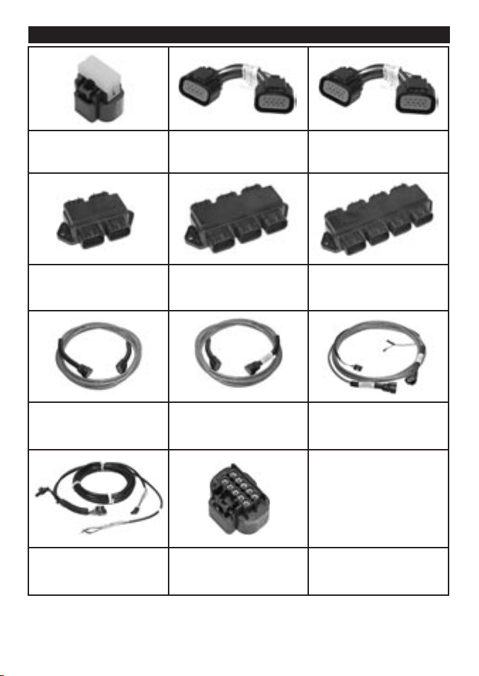
Appendix C - Mercury SmartCraft accessories
859318T1
Termination resistor
8784924
SmartCraft junc tion box
– 4 way
879968T (6, 10, 15, 20, 30)
SmartCraft wiring harness
892452A01
Smartcraf t cable adaptor
(male/male)
8784926
SmartCraft junc tion box
– 6 way
879981T (10,15, 20, 30)
SmartCraft wiring harness with
1 terminator
892453A01
SmartCraft cable adaptor
(female/female)
8784928
SmartCraft junc tion box
– 8 way
879982T (20, 30)
SmartCraft wiring harness with
2 terminators
859743T2
SmartCraft accessory
harness (fuel/oil)
859318T2
SmartCraft weather cap
37NAVMAN SmartCraft Gateways Installation and Operation Manual
Page 38

Appendix D How to contact us
NORTH AMERICA
BNT - Marine Electronics
30 Sudbury Rd, Acton, MA 01720.
Toll Free: +1 866 628 6261
Fax: +1 978 897 8264
e-mail: sales@navmanusa.com
web: www.navman.com
OCEANIA
Australia
Navman Australia Pty. Limited
Suite 2, 408 Victoria Road
Gladesville, NSW 2111, Australia.
Ph: +61 2 9879 9000
Fax: +61 2 9879 9001
e-mail: sales@navman.com.au
web: www.navman.com
New Zealand
Absolute Marine Ltd.
Unit B, 138 Harris Road,
East Tamaki, Auckland.
Ph: +64 9 273 9273
Fax: +64 9 273 9099
e-mail: navman@absolutemarine.co.nz
Papua New Guinea
Lohberger Engineering,
Lawes Road, Konedobu.
PO Box 810, Port Moresby.
Ph: +675 321 2122
Fax: +675 321 2704
e-mail: loheng@online.net.pg
web: www.lohberger.com.pg
LATIN AMERICA
Argentina
Costanera Uno S.A.
Av Pte Ramón S. Castillo y Calle 13
Zip 1425 Buenos Aires, Argentina.
Ph: +54 11 4312 4545
Fax +54 11 4312 5258
e-mail: purchase@costanerauno.com.ar
web: www.costanerauno.ar
Brazil
Equinautic Com Imp Exp de Equip
Nauticos Ltda.
Rua Ernesto Paiva, 139
Clube dos Jangadeiros
Porto Alegre - RS - Brasil
CEP: 91900-200.
Ph: +55 51 3268 6675
+55 51 3269 2975
Fax: +55 51 3268 1034
e-mail: equinautic@equinautic.com.br
web: www.equinautic.com.br
REALMARINE
Av Inf Dom Henrique s/nº - Loja 12
Marina da Glória - Rio de Janeiro - R.J.
Brasil
Cep: 2021-140
Ph: +55 21 3235-6222
Fax: +55 21 3235-6228
e-mail: vendas@realmarine.com.br
website: www.realmarine.com.br
Chile
Equimar
Manuel Rodrigurez 27
Santiago, Chile.
Ph: +56 2 698 0055
Fax +56 2 698 3765
e-mail: mmontecinos@equimar.cl
Mera Vennik
Colon 1148, Talcahuano,
4262798, Chile.
Ph: +56 41 541 752
Fax +56 41 543 489
e-mail: meravennik@entel.chile.net
Mexico
Mercury Marine de Mexico
Anastacio Bustamente #76
Interior 6 C olonia Fr ancisco Z arabia,
Zapapan, Jalisco, C.P. 45236 Mexico.
Ph: +52 33 3283 1030
Fax: +52 33 3283 1034
web: www.equinautic.com.br
Uruguay
Alvaro Burmudez , Nautica
Puerto del Buceo
11300 Montevid eo, Uruguay.
Phone & Fax +59 82 628 6562
e-mail : alvaro@ nautica.com.uy
web: www.nauti ca.com.uy
ASIA
China
Peaceful Marine Electronics Co. Ltd.
Guangzhou, Hong Kong, Dalian,
Qingdao, Shanghai
1701 Yanjiang Building
195 Yan Jiang Zhong Rd. 510115
Guangzhou, China.
Ph: +86 20 3869 8839
Fax: +86 20 3869 8780
e-mail: sales@peaceful-marine.com
web: www.peaceful-marine.com
India
Access India Overseas Pvt. Ltd.
A-98, Sector 21,
Noida - 201 301, India.
Ph: +91 120 244 2697
TeleFax: +91 120 253 7881
Mobile: +91 98115 04557
e-mail: vkapil@del3.vsnl.net.in
Esmario Export Enterprises
Block No. F-1, 3rd Floor, Surya Towers
Sardar Patel Rd, Secunderbad 500 003.
Ph: +91 40 2784 5163
Fax: +91 40 2784 0595
e-mail: gjfeee@hd1.vsnl.net.in
web: www.esmario.com
Korea
Kumhomarine Technology Co. Ltd.
#604-842, 2F, 1118-15, Janglim1-Dong,
Saha-Gu, Busan, Korea.
Ph: +82 51 293 8589
Fax: +82 51 265 8984
e-mail: info@kumhomarine.com
web: www.kumhomarine.com
Japan
PlusGain Inc.
1-A 324-3 Matunoki-Tyou
Takayama-City, Gifu-Ken, Japan
Ph: +81 577 36-1263
Fax: +81 577 36-1296
email: info@plusgain.co.jp
web: www.plusgain.co.jp
Maldives
Maizan Electronics Pte. Ltd.
Henveyru, 08 Sosunmagu.
Male', Maldives.
Mobile: +960 78 24 44
Ph: +960 32 32 11
Fax: +960 32 57 07
e-mail: ahmed@maizan.com.mv
Singapore an d Malaysia, Brunei
and Indonesi a
RIQ PTE Ltd.
Blk 3007, 81 Ubi Road 1, #02-440,
Singapore 408701.
Ph: +65 6741 3723
Fax : +65 6741 3746
e-mail: email@riq.com.sg
web: www.riq.com.sg
NAVMAN SmartCraft Gateways Installation and Operation Manual38
www.navman.com
Taiwan
Seafirst International Corporation
No. 281, Hou-An Road, Chien-Chen
Dist. Kaohsiung, Taiwan R.O.C.
Ph: +886 7 831 2688
Fax: +886 7 831 5001
e-mail: seafirst@seed.net.tw
web: www.seafirst.com.tw
Thailand
PING Electric Co., Ltd.
2/80 Sreesutus Road,
Russada Muang
Phuket 83000
Thailand
Tel: +66 (76) 224847
Fax: +66 (76) 252144
pingelectric@yahoo.com
Vietnam
HaiDang Co. Ltd.
763 Le Hong Phong St. Ward 12
District 10, Hochiminh City, Vietnam
Ph: +84 8 863 2159
Fax: +84 8 863 2524
e-mail: haidang-co@hcm.vnn.vn
web: www.haidangvn.com
MIDDLE EAST
United Arab Emira tes
Kuwait, Oman , Saudi Arabia , Bahrain
and Qatar
Abdullah Moh’d Ibrahim Trading, opp
Creak Rd. Baniyas Road, Dubai.
Ph: +971 4 229 1195
Fax: +971 4 229 1198
e-mail: sales@amitdubai.com
Egypt
18 Abou El-Ataheya St., via Abbas
Al-Akkad St.,
Nasr City, Cairo Egypt
Ph: +202 274 2911
+202 272 8493
Fax: +202 274 5219
e-mail: seet@internetegypt.com
Lebanon
Balco Stores
Balco Building, Moutran Street,
Tripoli (via Beirut). - Lebanon
P.O. Box: 622.
Ph: +961 6 624 512
Fax: +961 6 628 211
e-mail: balco@cyberia.net.lb
AFRICA
South Africa
Pertec (Pty) Ltd (Coastal Division)
16 Paarden Eiland Road.
Paarden Eiland, 7405
PO Box 527,
Paarden Eiland, 7420
Cape Town, South Afric a.
Ph: +27 2 1 508 4707
Fax: +27 21 508 4888
e-mail: info@kfa.c o.za
web: www.pertec.co.za
EUROPE
Plastimo International
15, rue Ingénieur Verrière,
BP435,
56325 Lorient Cedex.
Ph: +33 2 97 87 36 36
Fax: +33 2 97 87 36 49
e-mail: plastimo@plastimo.fr
web: www.plastimo.fr
OTHER COUNTRIE S IN EUROPE
Norway
ProNav AS
Fiskarvik Maritime Senter,
Hovlandsveien 52,
N-4370 Egersund, Norway.
Ph: +47 51 494 300
Fax: +47 51 492 100
e-mail: mail@pronav.no
web: www.pronav.no
Finland
Vator Oy
Puuskarinne 8,
00850 Helsinki, Finland.
Ph: +35 8 040 300 7212
Fax: +35 8 040 300 7200
e-mail: info@vator.com
web: www.vator.com
Croatia
Meridian Projekt d.o.o.
Savska 58,
Ph: +38 5 1 617 6364
Fax: +38 5 1 617 6365
e-mail: navman@meridianprojekt.com
web: www.meridianprojekt.com
HEADQUARTER S
Navman NZ Limited
7-21 Kawana St.
Northcote.
P.O. Box 68 155,
Newton,
Auckland,
New Zealand.
Ph: +64 9 481 0500
Fax: +64 9 481 0590
e-mail: marine.sales@navman.com
web: www.navman.com
Page 39

Made in New Zealand
MN000185F
S ma r tC ra f t Ga te wa y s
Lon 174° 44.535’E
Lat 36° 48.404’S
NAVMAN
 Loading...