

Page 1
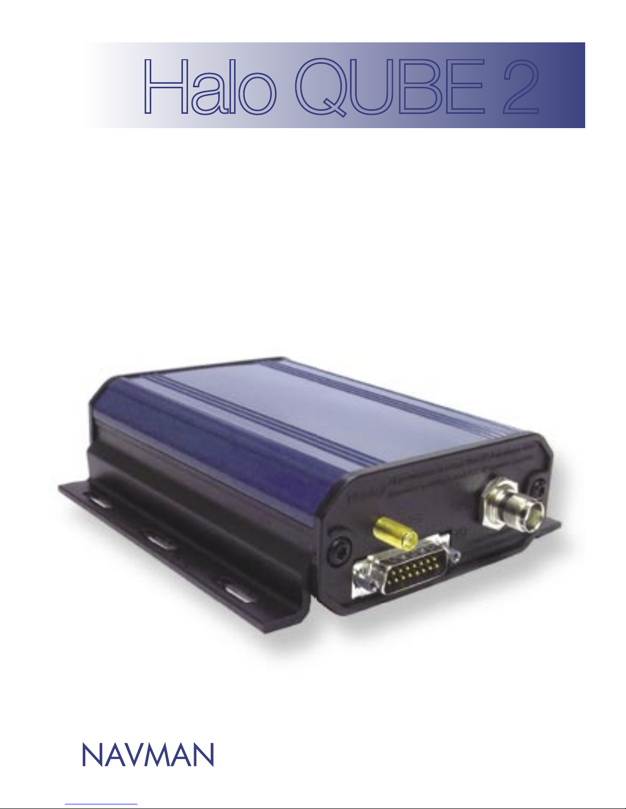
Halo QUBE 2
V1.0
Installation Manual
Europe / New Zealand Edition
Page 2

2
Halo QUBE 2 | Installation Guide V1.0
Important Notice
It is the Owner’s sole responsibility to install and use the Halo QUBE system (the Products) in
a manner that will not cause accidents, personal injury or property damage. For the purposes
of this notice, “Owner”, “you” and “your” means the party (including any person authorized
by that party to use and/or install the Product) that has either: (a) purchased the Product;
or (b) leased the Product from Navman NZ Limited or its related companies (Navman). The
Operator of this Product is solely responsible for observing safe driving practices. The choice,
location, and installation of all components of the Product is critical. If installation is not correct,
the Product may not perform at its designed potential or specifications. If in doubt, consult
your Navman dealer. Ensure that any mounting holes that are cut in the vehicle are in a safe
position and will not weaken the vehicle’s structure or compromise the safety of the vehicle or
its occupants. If in doubt, consult your vehicle’s manufacturer.
TO THE MAXIMUM EXTENT PERMITTED BY LAW, ALL REPRESENTATIONS AND
WARRANTIES (EXCEPT ANY WHICH MAY NOT LAWFULLY BE EXCLUDED) ARE
EXPRESSLY EXCLUDED, INCLUDING WITHOUT PREJUDICE TO THE GENERALITY OF THE
FOREGOING, THE IMPLIED WARRANTIES OF MERCHANTABILITY AND FITNESS FOR A
PARTICULAR PURPOSE. TO THE
MAXIMUM EXTENT PERMITTED BY LAW NAVMAN DISCLAIMS ALL LIABILITY ARISING
OUT OF OR IN CONNECTION WITH THE PRODUCT (INCLUDING ANY USE OF THIS
PRODUCT IN A WAY THAT MAY CAUSE ACCIDENTS, DAMAGE OR VIOLATE THE LAW).
As Navman is continuously improving this Product, Navman may make changes to the
Product at any time which may not be reflected in this document. Please contact your nearest
Navman office if you require any further assistance. Copyright © 2003 Navman NZ Limited,
New Zealand. All rights reserved. Navman is a registered trademark of Navman NZ Limited.
Page 3

3
Halo QUBE 2 | Installation Manual V1.0
Contents
Introduction .......................................................................... 4
What comes with the Halo QUBE 2 ..................................... 4
Quick Install - 3-Wire Basic Tracking .................................... 5
Installation ............................................................................. 6
Wiring ................................................................................... 8
Connecting an External ConEX .......................................... 11
Testing ................................................................................ 12
Fault Finding ....................................................................... 12
Specifications ..................................................................... 13
Conditions of Sale & Warranty ............................................ 14
Contacts ............................................................................. 15
Notes .................................................................................. 16
Page 4

4
Halo QUBE 2 | Installation Guide V1.0
Introduction
The Navman Halo Qube 2 is an Automatic Vehicle Location unit (AVL) that is installed into fl eet vehicles.
It communicates with a server, allowing vehicle information to be stored and monitored.
It is a combined GPS (Global Positioning System) and communications product that contains:
• A GPS receiver, providing accurate location data.
• A cellular modem, enabling data to be effi ciently transferred.
• An on-board microprocessor for intelligent processing and storage of data, and external
communication.
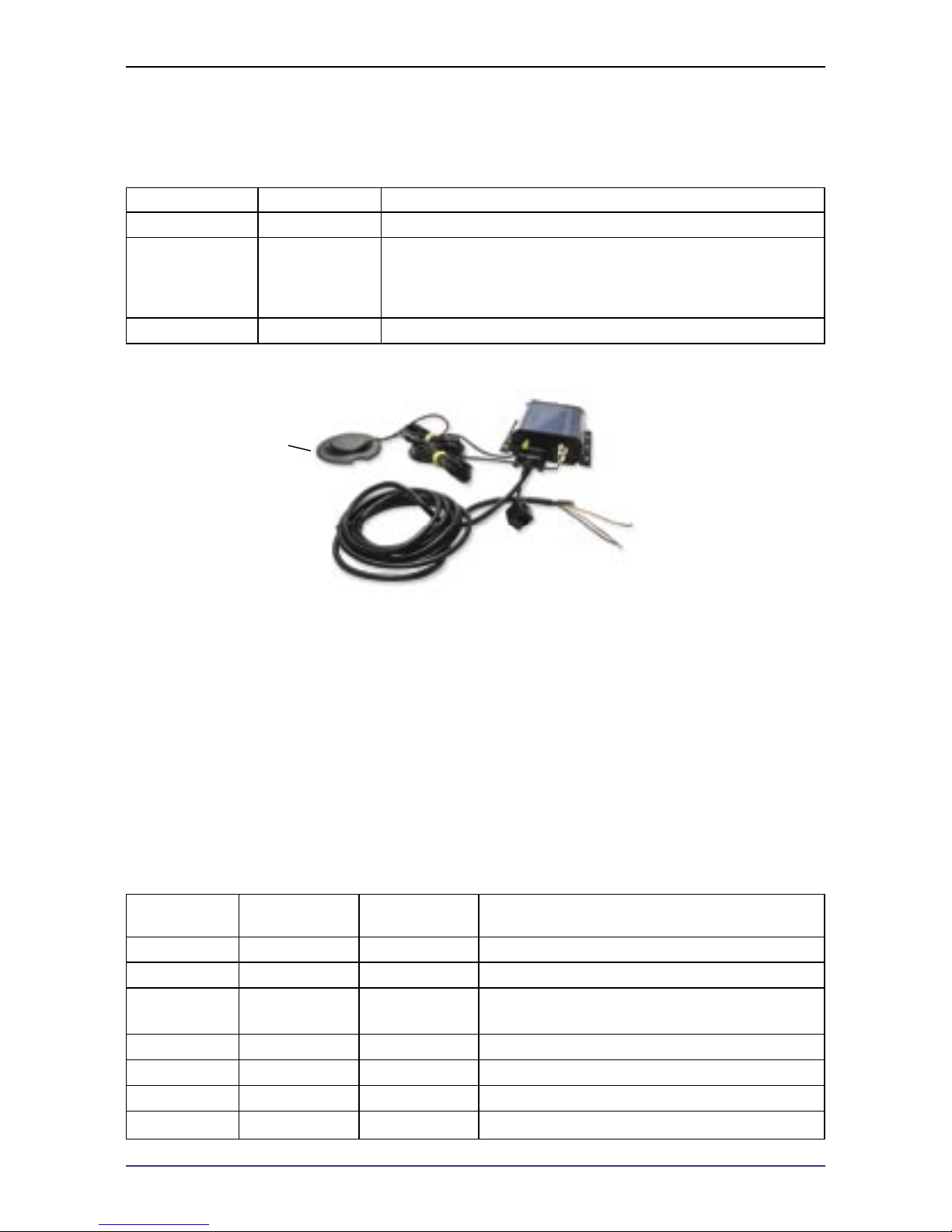
What comes with the Halo QUBE 2
1. Halo Qube 2 – Navman vehicle tracking unit.
2. Tax disk antenna. Combination GPS / GPRS. (Optional).
3. Vehicle connection cable. Either confi guration A or confi guration B (B shown).
4. Mounting rails for the Halo Qube 2.
5. Mounting Hardware for Halo Qube 2.
6. This installation manual.
Page 5
Red = +12/24 V Battery
Tax Disk Antenna
Pink = ignition “ON”
(NOT Accessories)
Black = Ground
5
Halo QUBE 2 | Installation Manual V1.0
Quick Install - 3-Wire Basic Tracking
Power Connection
Wire Colour Function Description
Red +12/24 V Main Power Connection - Connect to fused supply
Pink Ignition
Positive input from vehicle when the key is in the IGNITION
position (not the accessory position). This signal must
remain on DURING starting of the vehicle - Connect to a
fused supply.
Black GND Vehicle ground / chassis connection
Note: Please individually insulate any bare ends that are not connected.
Recommended Mounting
• Under the driver or passenger’s seat.
• In or under the dash.
• In the boot / trunk area.
• Where it is not excessively hot.
• Where it is dry.
• Where there is not excessive vibration.
• Should allow MDT/ PDT connection.
• Should allow the diagnostics LED’s to be seen
• Should allow suffi cient clearance to plug and unplug the connectors while mounted.
Status LED Indicators
LED
Display
State
Normal
Operation
Description
Power On
Power ON, Unit awake
Slow Flash Sleep mode
Off
No Power -
Note: The Qube 2 should always be powered.
GPS On
GPS fi x
Off No GPS fi x
GPRS On
Data connection to cellular network
Off No data connection
Page 6

6
Halo QUBE 2 | Installation Guide V1.0
Installation
Location / Mounting
Install the Qube 2:
• Under the driver or passenger’s seat
• In or under the dash
• In the boot / trunk area
The chosen location should:
• Allow for later connection of the MDT or PDT.
• Be dry
• Not have excessive vibration.
• Not be excessively hot.
• Allow the antennas and cabling to easily connect to the Qube 2.
• Allow the diagnostics LED’s can be seen
• Allow sufficient clearance to plug and unplug Qube 2, while mounted.
Mount the unit using the supplied self-tapping screws and washers, placed through the slots in the
side rails. The side mounting rails are supplied fitted to the Qube 2 ready for installation. If a different
side mounting format is required, the mounting rails may be turned over or removed completely.
There are two types of mounting rails. Type A will clip and unclip from the side of the Qube 2 by
applying pressure on the foot of the mounting rail. Type B requires the end cap to be removed, and
the rails slid out to change their orientation. Only one type will be supplied with the unit.
Connect the antenna cables to the correct connector. Both the Cellular connector (TNC) and the
GPS (SMA) are screw on connectors, which should be hand tightened only. Connect the DB15
connector to the socket and hand tighten the two locking screws.
Ensure all cables are secured out of the way, so they will not be damaged, walked on, or have other
articles placed on them.
Important Notice
• Before you begin ensure that drilling will not damage the vehicles structure, wiring or
equipment.
• Ensure the Qube 2 cables, mounting screws etc will pose no hazard to the occupants of the
vehicle.
Page 7

Cellular antenna
GPS antenna
7
Halo QUBE 2 | Installation Manual V1.0
Antenna
Position the antennas so that:
• The GPS antenna has a clear view of as much of the sky as possible.
• They are mounted as far away as practical from any other antenna, to minimize the risk of
interference.
• The cables can be easily routed to the Qube 2
Important Notice
The cellular antenna must be placed at least 20 cm (8¨) away from any person to meet FCC RF
exposure requirements.
Windscreen Combination (Tax Disk) Antenna
This is an internal combination GPS/Cellular antenna. The ideal mounting angle is 45°. This antenna
is not suitable for mounting on vertical windows (e.g. side windows or near vertical windscreens.)
Position the Tax Disk antenna so that the antenna:
• The Flat side is facing outside.
• Mounts directly on the windscreen, at least
13 mm (½¨) from window frame.
• Does not obstruct driver vision (normally
placed on the passenger side).
• Allows mounting with notch to the top, so
that a tax disk may be inserted.
Note: This antenna is suitable for internal mounting
only. Some tinted, heated or other windscreens may
not be suitable for use with this antenna. If unsure, test the
antenna through the windscreen before mounting.
Magnetic Mounting Antennas
Ensure that the antenna is placed, so the cables
can easily be routed to the Qube 2.
The GPS antenna has a clear view of as much of
the sky as possible.
Other antenna options are available from your
installer.
Page 8

8
Halo QUBE 2 | Installation Guide V1.0
Wiring
Cable A
Has a long cable with a RJ45 Plug, a short cable with a DB9 plug, and a single cable with bare ends for
all other connections.
Cable B
Has an RJ45 socket very close to the main plug (DB15), and a single long cable with bare ends for all
other connections.
Power Connection - Bare wires
Cable A Cable B Function Description
Red Red +12/24 V
Main Power Connection - Connect to
a fused supply
Pink Pink Ignition
Positive input from vehicle when the
key is in the IGNITION position (not
the accessory position). This signal
must remain on DURING starting
of the vehicle - Connect to a fused
supply.
Black Black GND Vechicle ground / chassis connection
Important Notice
If fitting a MDT-800 (Mobile Data Terminal) the main power connection (red wire) must be
connected to +12 V DC only. The Qube 2 ignition and Multi IO lines may still be connected to
24 V DC.
MDT or PDT Connection
RJ45 Connector - Cable A (Male plug), Cable B (Female socket)
Cable A Cable B Function Description
Pin - 1 Pin - 1 GND Ground
Pin - 2 Pin - 2 +12/24 V Power
Pin - 4 Pin - 4 Serial RxD Serial data Input
Pin - 5 Pin - 5 Serial TxD Serial data Output
Page 9

9
Halo QUBE 2 | Installation Manual V1.0
Connecting the Auxiliary Devices
The Qube 2 is equipped with additional IO that can be connected to auxiliary devices in the vehicle.
These Allow the Qube to generate events based on inputs from these devices.
Multi-IO. Each multi IO can be configured as digital input, analogue input or digital output.
Serial. There are two RS232 serial ports that can be configured as serial capture ports, MDT or
External ConEX ports etc. For serial Capture, a configuration string is sent via the server.
Cable A Cable B Function Description
Yellow Yellow Multi IO-1 Digital IN, analogue IN, digital OUT
Green Green Multi IO-2 Digital IN, analogue IN, digital OUT
Blue Blue Multi IO-3 Digital IN, analogue IN, digital OUT
Grey Grey A - GND Analogue GND reference
White White +3V7 OUT Reference voltage if required
DB9 – Pin 3 Purple Serial TxD Serial data OUT
DB9 – Pin 2 Brown Serial RxD Serial data IN
DB9 – Pin 7 Light Green Serial RTS Serial data flow control OUT
DB9 – Pin 8 Black/White Serial CTS Serial data flow control IN
DB9 – Pin 5 - Serial GND Serial GND
Digital Inputs
These are inputs that are either on or off. The polarity is not important but must be noted for the
correct configuration to be sent to the vehicle. All digital inputs must be sourcing inputs.
Page 10

Sensor Max. Resistance:
0 to 10k Rpullup = 1k ¼ W
10k to 20k Rsenor = 2k2 ¼ W
R1 =
0.00015
(V
sensor max
- 5 V DC)
10
Halo QUBE 2 | Installation Guide V1.0
Analogue Inputs
These connect to devices that have a variable voltage output. As the input voltage range (0 to 5
V DC) may not match the sensors range, the input may have to be scaled. In order to scale the
voltages correctly, you should calculate the maximum sensor voltage to scale to 5 V DC at the
ConEX input.
Digital Outputs
These outputs are an “open collector” transistor type arrangement. The outputs will pull low when
activated. The outputs have an over current trip. If tripped the output must be changed to the off
state, or have a power cycle to reset the current trip.
Battery Backup connections
The Qube 2 has the facility to connect an external battery to allow for a battery backup operation.
This allows the Qube 2 to normally run off the main supply, and also trickle-charge the backup
battery. When the main power fails or is disconnected, the Qube 2 will continue to run by drawing
power from the backup battery. (e.g. A gel cell type battery).
Connect the orange wire directly to the positive of the backup battery, and ground the negative side
of the battery at the same point where the Qube 2’s black wire is grounded. If the Qube 2 is powered
off 24 V DC, then the backup battery must also be 24 V DC. If powered from 12 V DC the battery
must be 12 V DC.
Note: As the charging circuit is simplistic, the backup battery will only fully charge when the vehicle is operating (ie. the
vehicle’s alternator is supplying the higher charging voltage.)
Page 11

Qube 2
Combination GPS/GPRS
Antenna
ConEx Unit
Connect Vehicle Power
Connections here
11
Halo QUBE 2 | Installation Manual V1.0
Connecting an External ConEX
Note: Please check with your distributor, to see if this feature is available yet.
An external ConEX would be connected if: The user requires additional IO lines, additional serial capture
port, or has custom ConEX code that needs to be used with their system.
The Qube 2 will connect into the connector marked “HALO - QUBE”. The wire colours do not directly
match. Please connect the Qube 2 using the table below.
Please refer to the ConEX installation manual for all other ConEX connections.
RJ45 Connector - Cable A Male plug, Cable B Female socket
ConEX
Connections
Cable A Cable B
Qube 2
Function
Description
RD Red Red +12/24 V Power
OR Pink Pink Ignition Ignition
GR - - - Do not connect
WH - - - Do not connect
YE - - - Do not connect
BL DB9 - Pin 3 Purple TxD Serial data output
BR DB9 - Pin 2 Brown RxD Serial data input
BK Black Black GND Ground
Note: The MDT port on the ConEX box will no longer function. Please use the RJ45 connector on the Qube 2 cable to
attach an MDT / PDT etc.
Page 12

12
Halo QUBE 2 | Installation Guide V1.0
Testing
Check Correct Ignition connection
Use a multi-meter to measure the voltage at the ignition line connected to the Qube 2.
1. Turn the key to the accessories position. Check that there is no voltage on the ignition line.
2. Turn the key to the IGNITION position. Ensure that +12 / 24 V DC is present at ignition line.
3. Watching the meter, start the vehicle and ensure that the voltage does remain ON during starting.
If any of these tests fail, the Qube 2 is not connected to the correct signal. Please find the correct wire
Check Data and GPS
1. Ensure the vehicle is outside, so the GPS antenna has a clear view of the sky, and there is good
cellular coverage.
2. Turn the Ignition Key on to the ignition position.
3. Check that all 3 LED’s come ON. This may take up to 15 minutes, but is normally less than 2
minutes.
Fault Finding
Power LED fails to light
Check that the +12 / 24 V wire has permanent power connected
to it.
Check the DB15 I/O connector is correctly connected, and the
securing screws are hand tightened onto the Qube 2.
GPS LED fails to light
Ensure that the antenna is up the correct way, and has a clear
view of as much of the sky as possible.
Check the antenna connectors are correctly connected, and
hand tightened onto the Qube 2 connectors.
It may take up to 15 minutes for a first GPS fix after the unit has
been shipped un-powered to a new location.
GPRS LED fails to light
Check the antenna connectors are correctly connected, and
hand tightened onto the Qube 2 connectors.
Check if the area has GPRS coverage.
Page 13

Height = 42mm
Dimensions:
13
Halo QUBE 2 | Installation Manual V1.0
Specifications
Physical
• Weight: 370g
• Case Material: Aluminium Extrusion.
• End Caps: Bayblend FR110. Fire
retardant ABS/Polycarb blend.
• Feet: Unplasticised PVC. Fire retardant
Power Supply
• Supply voltage range: 8 to 30 V DC
• Typical Current consumption:
12 V DC Tracking 75 mA sleep 25 mA
24 V DC Tracking 45 mA sleep 20 mA
Temperature
• Storage: -40 to +85ºC
(-40ºF to +185ºF)
• Operation: -20 to +60ºC
(-4ºF to +140ºF)
Ignition Input
• Absolute Maximum Voltage: 30 V
(Independent of supply)
Serial Interface
• RS232 x2
Digital Inputs
• Input Voltage LOW: < 1.0 V
• Input Voltage HIGH: > 4.0 V
• Absolute Maximum Voltage: 30 V
(Independent of supply)
Analogue Inputs
• Voltage Range: 0 to 5 V DC
• ADC Resolution: 10 bit (4.88 mV/step)
• Absolute Maximum Voltage: 30 V
(Independent of supply)
Digital Outputs
• Maximum sink current 250 mA
(Current limited)
EMC Compliance
• USA (FCC): Part 15 class B
• NZ & Australia (C-Tick): AS / NZS CISPR
22:2002
• Europe (e11 and CE)
Page 14

14
Halo QUBE 2 | Installation Guide V1.0
Conditions of Sale & Warranty
Important Notice
Some of the following terms and conditions vary from country to country. Please check with your
Navman dealer from whom you purchased your product.
A. Conditions of Sale
Except to the extent otherwise required by the laws of the country in which the accompanying
product (“the product”) is sold the manufacturer of the product Navman NZ Limited (“Navman”) - has
no liability in respect of the product beyond the warranty hereunder provided. Where liability may not
be excluded but may be limited to repair or replacement or the supply of equivalent goods or for the
payment of the cost of replacing the goods or of acquiring equivalent goods, liability is so limited.
B. Manufacturers warranty
Warranty Period - 1 year from the date of purchase.
Extent of warranty - Subject to the following conditions Navman will rectify any defect occurring in
the product of which notice in writing is received by Navman or its approved distributor within the
Warranty Period.
Conditions:
1. Repairs may only be carried out by a Service Centre approved by Navman.
2. Repairs as above will be carried out at no cost to the owner subject to these conditions.
3. The cost of returning the goods to an approved dealer shall be met by the owner.
4. Warranty does not extend to accessories or defects or injuries caused or resulting from causes
not attributable to faulty parts or the manufacturer of the product including, but not limited to,
defect or injuries caused by or resulting from misuse, abuse, neglect, accidental damage, incorrect
installation, water damage, use of consumables other than those approved by Navman or any
alterations to the product not approved by Navman.
5. No warranty claim accepted without sales documentation.
6. Navman may, at its discretion, replace the product instead of repairing it.
C. Acceptance of Conditions of Sale
In consideration of this warranty the purchaser accepts the limitations of liability as set out in the
conditions of sale.
Page 15

15
Halo QUBE 2 | Installation Manual V1.0
Contacts
Navman NZ Limited
13-17 Kawana Street, Northcote
PO Box 68 155, Newton
Auckland
NEW ZEALAND
Tel: +64 (0)9 481 0500
Fax: +64 (0)9 480 3176
Customer Support: fleet.support@navman.com
Website: www.navman.com
Navman Wireless NZ
13-17 Kawana Street, Northcote
PO Box 68 155, Newton
Auckland
NEW ZEALAND
Info: 0800 4 GPS FLEET (0800 447 735)
Customer Support: 0800 GPS FLEET (0800 477 353)
Email: wirelessnzsupport@navman.com
Website: www.navmanwireless.co.nz
Navman Wireless UK
Innovation Centre 2
Keele University Science Park
Keele, Staffordshire, ST5 5NH
UNITED KINGDOM
Tel: +44 (0) 1782 55 79 50
Fax: +44 (0) 1782 55 79 79
Email: info@navmanwireless.co.uk
Website: www.navmanwireless.co.uk
Navman Wireless Australia
Navman Australia Pty. Ltd.
Suite 2, 408 Victoria Road
PO Box 479
Gladesville NSW 2111
AUSTRALIA
Tel: 61 2 9879 9000
Fax: 61 2 9879 9001
Website: www.navman.com
Page 16

16
Halo QUBE 2 | Installation Guide V1.0
Notes
MN000032A
 Loading...