

Page 1
M22
STEREO POWER AMPLIFIER
DigitalPowerDrive
®
M22
Stereo Power Amplier
ENGLISHFRANÇAISESPAÑOLITALIANODEUTSCHNEDERLANDSSVENSKAРУССКИЙ
© NAD M22
Owner’s Manual
Page 2
IMPORTANT SAFETY INSTRUCTIONS
ENGLISH FRANÇAIS ESPAÑOL ITALIANO DEUTSCH NEDERLANDS SVENSKA РУССКИЙ
SAVE THESE INSTRUCTIONS FOR LATER USE.
FOLLOW ALL WARNINGS AND INSTRUCTIONS MARKED ON THE AUDIO
EQUIPMENT.
1 Read instructions - All the safety and operating instructions should be
read before the product is operated.
2 Retain instructions - The safety and operating instructions should be
retained for future reference.
3 Heed Warnings - All warnings on the product and in the operating
instructions should be adhered to.
4 Follow Instructions - All operating and use instructions should be
followed.
5 Cleaning - Unplug this product from the wall outlet before cleaning.
Do not use liquid cleaners or aerosol cleaners. Use a damp cloth for
cleaning.
6 Attachments - Do not use attachments not recommended by the
product manufacturer as they may cause hazards.
7 Water and Moisture - Do not use this product near water-for example,
near a bath tub, wash bowl, kitchen sink, or laundry tub; in a wet
basement; or near a swimming pool; and the like.
8 Accessories - Do not place this product on an unstable cart, stand,
tripod, bracket, or table. The product may fall, causing serious injury to
a child or adult, and serious damage to the product. Use only with a
cart, stand, tripod, bracket, or table recommended by the manufacturer,
or sold with the product. Any mounting of the product should follow
the manufacturer’s instructions, and should use a mounting accessory
recommended by the manufacturer.
9 A product and cart combination should be moved with care.
Quick stops, excessive force, and uneven surfaces may cause
the product and cart combination to overturn.
10 Ventilation - Slots and openings in the cabinet are provided for
ventilation and to ensure reliable operation of the product and to
protect it from overheating, and these openings must not be blocked
or covered. The openings should never be blocked by placing the
product on a bed, sofa, rug, or other similar surface. This product should
not be placed in a built-in installation such as a bookcase or rack unless
proper ventilation is provided or the manufacturer’s instructions have
been adhered to.
11 Power Sources - This product should be operated only from the type
of power source indicated on the marking label. If you are not sure of
the type of power supply to your home, consult your product dealer or
local power company.
The primary method of isolating the amplier from the mains supply
is to disconnect the mains plug. Ensure that the mains plug remains
accessible at all times. Unplug the AC power cord from the AC outlet if
the unit will not be used for several months or more.
12 Grounding or Polarization - This product may be equipped with a
polarized alternating-current line plug (a plug having one blade wider
than the other). This plug will t into the power outlet only one way.
This is a safety feature. If you are unable to insert the plug fully into the
outlet, try reversing the plug. If the plug should still fail to t, contact
your electrician to replace your obsolete outlet. Do not defeat the safety
purpose of the polarized plug.
13 Power - Cord Protection - Power-supply cords should be routed so that
they are not likely to be walked on or pinched by items placed upon or
against them, paying particular attention to cords at plugs, convenience
receptacles, and the point where they exit from the product.
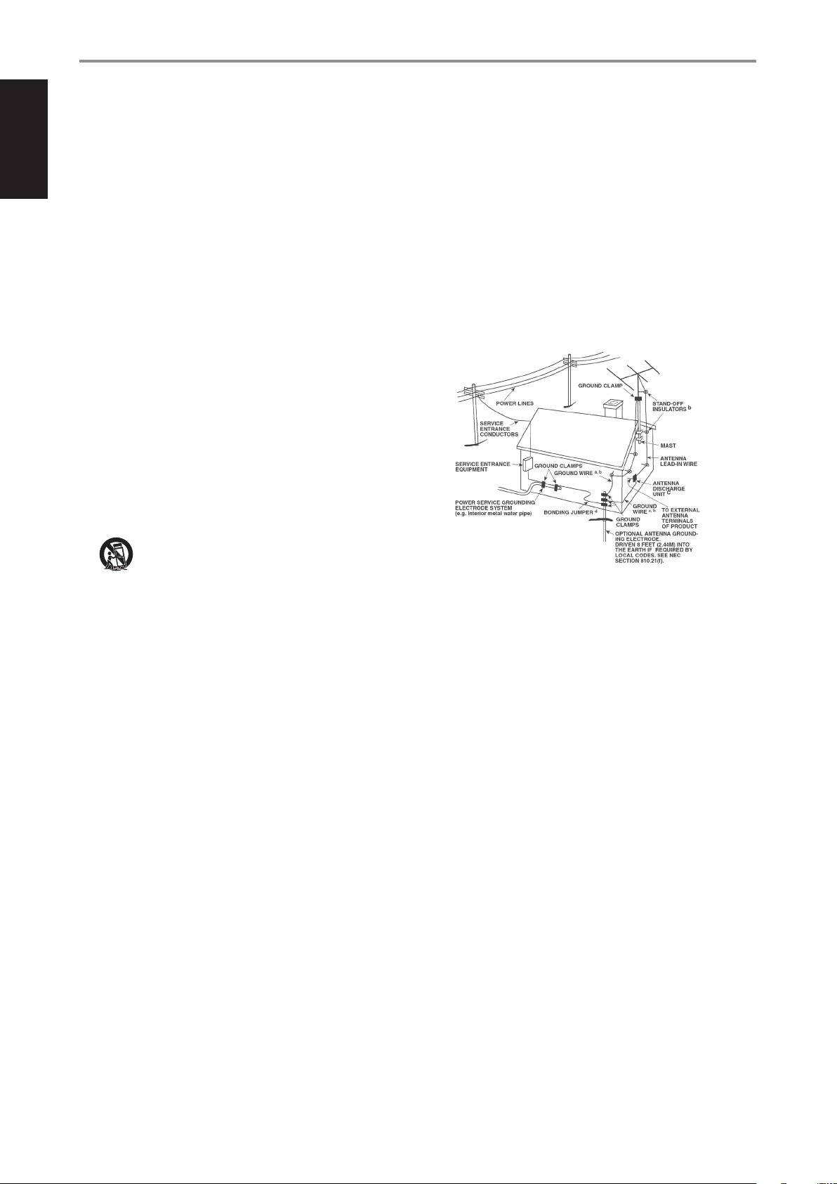
14 Outdoor Antenna Grounding - If an outside antenna or cable system
is connected to the product, be sure the antenna or cable system is
grounded so as to provide some protection against voltage surges
and built-up static charges. Article 810 of the National Electrical Code,
ANSI/NFPA 70, provides information with regard to proper grounding
of the mast and supporting structure, grounding of the lead-in wire
to an antenna discharge unit, size of grounding conductors, location
of antenna discharge unit, connection to grounding electrodes, and
requirements for the grounding electrode.
NOTE TO CATV SYSTEM INSTALLER
This reminder is provided to call the CAT V system installer’s attention to Section
820-40 of the NEC which provides guidelines for proper grounding and, in
particular, species that the cable ground shall be connected to the grounding
system of the building, as close to the point of cable entry as practical.
15 Lightning - For added protection for this product during a lightning
storm, or when it is left unattended and unused for long periods of
time, unplug it from the wall outlet and disconnect the antenna or
cable system. This will prevent damage to the product due to lightning
and power-line surges.
16 Power Lines - An outside antenna system should not be located in the
vicinity of overhead power lines or other electric light or power circuits,
or where it can fall into such power lines or circuits. When installing an
outside antenna system, extreme care should be taken to keep from
touching such power lines or circuits as contact with them might be
fatal.
17 Overloading - Do not overload wall outlets, extension cords, or
integral convenience receptacles as this can result in a risk of re or
electric shock.
18 Object and Liquid Entry - Never push objects of any kind into this
product through openings as they may touch dangerous voltage points
or short-out parts that could result in a re or electric shock. Never spill
liquid of any kind on the product.
WARNING: THE APPARATUS SHOULD NOT BE EXPOSED TO DRIPPING
OR SPLASHING, AND OBJECTS FILLED WITH LIQUIDS, SUCH AS VASES,
SHOULD NOT BE PLACED ON THE APPARATUS. AS WITH ANY ELECTRONIC
PRODUCTS, USE CARE NOT TO SPILL LIQUIDS INTO ANY PART OF THE
SYSTEM. LIQUIDS CAN CAUSE A FAILURE AND/OR A FIRE HAZARD.
2
Page 3
IMPORTANT SAFETY INSTRUCTIONS
19 Damage Requiring Service - Unplug this product from the wall outlet
and refer servicing to qualied service personnel under the following
conditions:
a) When the power-supply cord or plug is damaged.
b) If liquid has been spilled, or objects have fallen into the product.
c) If the product has been exposed to rain or water.
d) If the product does not operate normally by following the operating
instructions. Adjust only those controls that are covered by the operating
instructions as an improper adjustment of other controls may result in
damage and will often require extensive work by a qualied technician to
restore the product to its normal operation.
e) If the product has been dropped or damaged in any way.
f) when the product exhibits a distinct change in performance-this indicates a
need for service.
20 Replacement Parts - When replacement parts are required, be
sure the service technician has used replacement parts specified
by the manufacturer or have the same characteristics as the
original part. Unauthorized substitutions may result in fire, electric
shock, or other hazards.
21 Safety Check - Upon completion of any service or repairs to this
product, ask the service technician to perform safety checks to
determine that the product is in proper operating condition.
22 Wall or Ceiling Mounting - The product should be mounted to a wall
or ceiling only as recommended by the manufacturer.
23 Heat - The product should be situated away from heat sources such as
radiators, heat registers, stoves or other products (including ampliers)
that produce heat.
WARNING
TO REDUCE THE RISK OF FIRE OR ELECTRIC SHOCK, DO NOT EXPOSE THIS
PRODUCT TO RAIN OR MOISTURE.
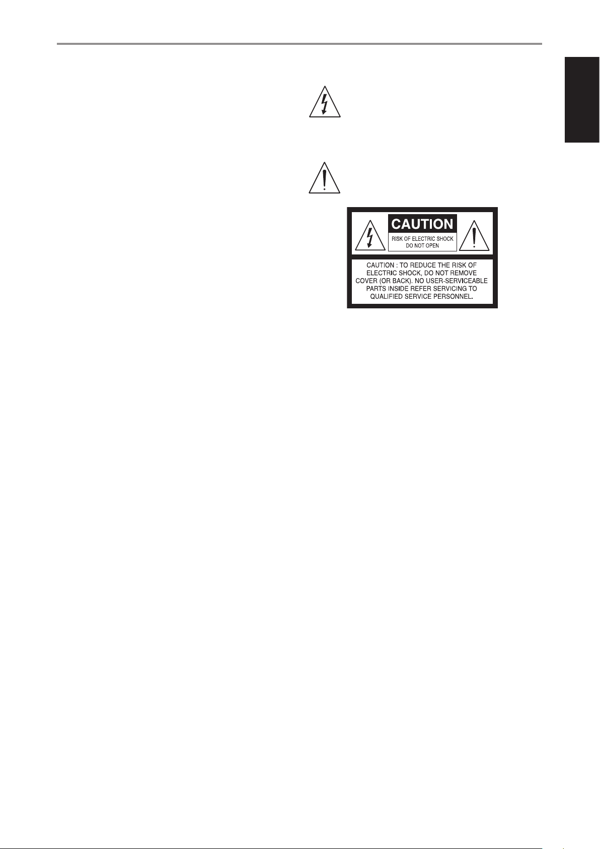
THE LIGHTNING FLASH WITH ARROWHEAD SYMBOL, WITHIN
AN EQUILATERAL TRIANGLE, IS INTENDED TO ALERT THE USER
TO THE PRESENCE OF UNINSULATED “DANGEROUS VOLTAGE”
WITHIN THE PRODUCT’S ENCLOSURE THAT MAYBE OF SUFFICIENT
MAGNITUDE TO CONSTITUTE A RISK OF ELECTRIC SHOCK TO
PERSONS.
THE EXCLAMATION POINT WITHIN AN EQUILATERAL TRIANGLE IS
INTENDED TO ALERT THE USER TO THE PRESENCE OF IMPORTANT
OPERATING AND MAINTENANCE (SERVICING) INSTRUCTIONS IN
THE LITERATURE ACCOMPANYING THE APPLIANCE.
The equipment draws its nominal non-operational power from the AC outlet
with its POWER switch at the ON position.
The socket-outlet shall be installed near the apparatus and shall be easily
accessible.
CAUTION
Changes or modications to this equipment not expressly approved by NAD
Electronics for compliance could void the user’s authority to operate this
equipment.
ENGLISHFRANÇAISESPAÑOLITALIANODEUTSCHNEDERLANDSSVENSKAРУССКИЙ
CAUTION
TO PREVENT ELECTRIC SHOCK, MATCH WIDE BLADE OF PLUG TO WIDE SLOT,
FULLY INSERT.
CAUTION REGARDING PLACEMENT
To maintain proper ventilation, be sure to leave a space around the unit (from
the largest outer dimensions including projections) that is equal to or greater
than shown below.
Left and Right Panels: 10 cm
Rear Panel: 10 cm
Top Panel: 10 cm
3
Page 4
ENGLISH FRANÇAIS ESPAÑOL ITALIANO DEUTSCH NEDERLANDS SVENSKA РУССКИЙ
IMPORTANT SAFETY INSTRUCTIONS
NOTES ON ENVIRONMENTAL PROTECTION
At the end of its useful life, this product must not be disposed
of with regular household waste but must be returned to a
collection point for the recycling of electrical and electronic
equipment. The symbol on the product, user’s manual and
packaging, point this out.
The materials can be reused in accordance with their markings. Through re-use,
recycling of raw materials or other forms of recycling of old products, you are
making an important contribution to the protection of our environment. Your
local administrative oce can advise you of the responsible waste disposal
point.
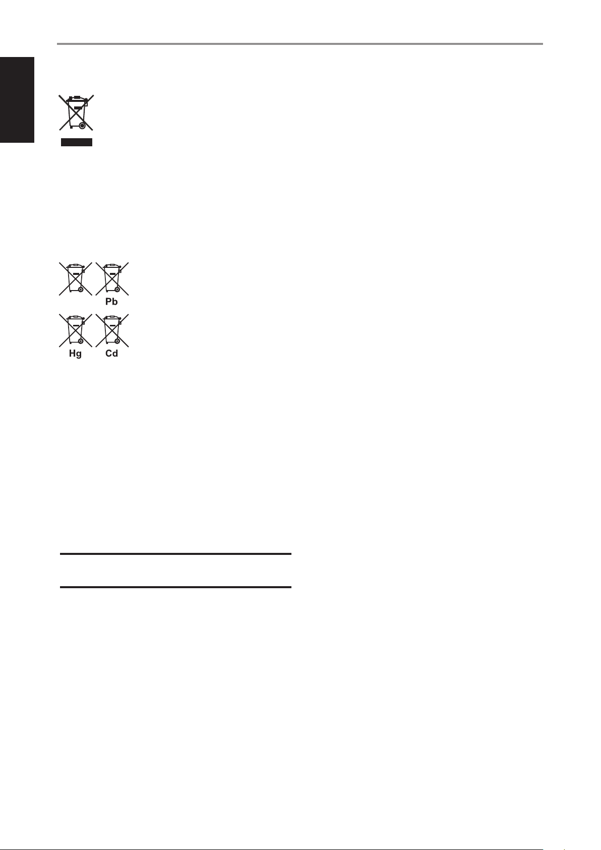
INFORMATION ABOUT COLLECTION AND DISPOSAL OF WASTE BATTERIES
DIRECTIVE 2006/66/EC OF THE EUROPEAN PARLIAMENT AND THE COUNCIL
OF EUROPEAN UNION FOR EUROPEAN CUSTOMERS ONLY
Batteries bearing any of these symbols indicate
that they should be treated as “separate collection”
and not as municipal waste. It is encouraged that
necessary measures are implemented to maximize
the separate collection of waste batteries and to
minimize the disposal of batteries as mixed municipal
waste.
End-users are exhorted not to dispose waste batteries
as unsorted municipal waste. In order to achieve
a high level of recycling waste batteries, discard waste batteries separately
and properly through an accessible collection point in your vicinity. For more
information about collection and recycling of waste batteries, please contact
your local municipality, your waste disposal service or the point of sale where
you purchased the items.
By ensuring compliance and conformance to proper disposal of waste
batteries, potential hazardous eects on human health is prevented and
the negative impact of batteries and waste batteries on the environment
is minimized, thus contributing to the protection, preservation and quality
improvement of the environment.
RECORD YOUR MODEL NUMBER NOW, WHILE YOU CAN SEE IT
The model and serial number of your new M22 are located on the back of
the cabinet. For your future convenience, we suggest that you record these
numbers here:
Model no: ......................................
Serial no.: . . . . . . . . . . . . . . . . . . . . . . . . . . . . . . . . . . . . . .
NAD is a trademark of NAD Electronics International, a division of Lenbrook Industries Limited
Copyright 2017, NAD Electronics International, a division of Lenbrook Industries Limited
4
Page 5

INTRODUCTION
GETTING STARTED
WHAT’S IN THE BOX
Packed with your M22 you will nd
• A detachable mains power cord
• Four pieces of magnetic feet
• USB ash drive
• Cleaning cloth
• Quick Setup Guide
QUICK SETUP GUIDE
In case you simply cannot wait to experience the performance of your new
M22, the following QUICK SETUP GUIDE is recommended to help you get
started.
Ensure that the M22 is unplugged before making any connections. It is
also advisable to power-down or unplug all associated components while
making or breaking any signal or AC power connections. Set the external
source's volume control to minimum level. External source can be a
preamplier, processor, amplier or any applicable device.
1 Set SELECT switch to BALANCED or SINGLE-ENDED. It is important that
the selection for ANALOG AUDIO INPUT must be the same for both L
(left) and R (right) channels.
2 Connect the analog audio output of your external source to the M22
rear panel’s BALANCED or SINGLE-ENDED analog audio input.
3 Connect your speakers to the LEFT and RIGHT SPEAKERS terminals of
M22.
4 Ensure that the supplied power cord’s female connector end is rmly
secured to M22’s AC Mains input socket and the male plug connected
to the mains power source.
5 Power up the external source ahead of the M22.
6 Set to ON the rear panel POWER switch of M22. The M22 goes to
standby mode as shown by the amber status condition of the Power
indicator.
7 Press o (Standby) button for the M22 to be powered up from standby
mode. The Power indicator will turn from amber to bright/white color.
The M22 is ready for operation.
8 Adjust the external source’s volume control according to desired
listening level.
BARE WIRES AND PIN CONNECTORS
WARNING: The terminals marked with this symbol
are hazardous live. External wiring connected to these
terminals requires installation by an instructed person or
the use of ready-made leads or cords.
Bare wires and pin sockets should be inserted into the hole in the shaft of
the terminal. Unscrew the speaker terminal’s bushing until the hole in the
screw shaft is revealed. Insert the pin or bare cable end into the hole and
secure the cable by tightening down the terminal’s bushing. Ensure bare
wire from the speaker cables does not touch the back panel or another
socket. Ensure that there is only 1/2” (1cm) of bare cable or pin and no loose
strands of speakers wire.
FEET INSTALLATION
The supplied magnetic feet can be easily installed by aligning and attaching
them to their corresponding foot shoe. Refer to the illustration below.
^
ENGLISHFRANÇAISESPAÑOLITALIANODEUTSCHNEDERLANDSSVENSKAРУССКИЙ
SAVE THE PACKAGING
Please save the box and all of the packaging in which your M22 arrived.
Should you move or otherwise need to transport your M22, this is by far the
safest container in which to do so. We’ve seen too many otherwise perfect
components damaged in transit for lack of a proper shipping carton, so
please: Save that box!
NOTES ON INSTALLATION
• Your unit should be placed on a rm, level surface.
• Avoid placing the unit inside a closed cabinet that is not well ventilated
as this may compromise the M22’s performance and reliability.
• Avoid placing the unit in direct sunlight or near sources of heat and
damp.
• Allow adequate ventilation.
• Do not place the unit on a soft surface like a carpet.
• For best performance, use quality speaker leads of 16 gauge (1.5mm2)
thickness or more.
• If the unit is not going to be used for some time, disconnect the plug
from the mains power source.
• Use a dry cloth for cleaning.
DO NOT REMOVE THE COVER; THERE ARE NO USERSERVICEABLE
PARTS INSIDE.
5
Page 6

ENGLISH FRANÇAIS ESPAÑOL ITALIANO DEUTSCH NEDERLANDS SVENSKA РУССКИЙ
IDENTIFICATION OF CONTROLS
FRONT PANEL
1
STEREO POWER AMPLIFIER
2
1 o (STANDBY)
• Press o (Standby) button for the M22 to be powered up from
standby mode. The Power indicator will turn from amber to bright/
white color.
• Press and hold o (Standby) button until M22 switches back to
standby mode. The Power indicator will turn to amber color at
standby mode.
• The o (Standby) button cannot activate the M22 with the rear
panel POWER switched o.
M22
2 POWER INDICATOR (NAD LOGO)
• The NAD logo in the front panel also serves as a Power indicator.
• Power indicator colors
• Bright/white: Normal operating mode
• Amber: Standby mode
• Red: Protect mode
DigitalPowerDrive
© NAD M22
IMPORTANT NOTE
For the o (Standby) button to activate, two conditions must be
completed.
• Plug-in the supplied mains power cord to a mains power source.
Connect corresponding end of the mains power cord to the AC mains
input of M22 and the plug connected to a mains power source.
• The rear panel POWER switch must be set to ON position.
AUTO STANDBY
The M22 can be setup to automatically go to standby mode if there is
no active source input within 30 minutes. Auto standby mode can be
enabled or disabled by the following steps.
Enable Auto Standby mode
• With M22 at operating mode, press and hold the rear panel LED
LEVEL button until the Power indicator (NAD logo) ashes once.
• At operating mode, the M22 will automatically go to standby mode
if there is no active source input within 30 minutes.
Disable Auto Standby mode
• With M22 at operating mode, press and hold the rear panel LED
LEVEL button until the Power indicator (NAD logo) ashes twice.
• At operating mode, M22 will not automatically go to standby mode
even if there is no active source input within 30 minutes. Press o to
switch M22 from operating mode to standby mode.
6
Page 7

1 12 23
IDENTIFICATION OF CONTROLS
REAR PANEL
ENGLISHFRANÇAISESPAÑOLITALIANODEUTSCHNEDERLANDSSVENSKAРУССКИЙ
220-230V
© NAD M22
123 54 45 6 7 98 1110 13
ATTENTION!
Ensure that the M22 is unplugged before making any connections. It is also advisable to power-down or unplug all associated components while making
or breaking any signal or AC power connections.
1 SINGLE-ENDED
• Use SINGLE-ENDED analog audio input for sources (preampliers or
processors) that are not equipped with BALANCED analog audio output.
• If SINGLE-ENDED is the selected audio input, ensure that the SELECT
switches for both L (Left) and R (Right) channels of ANALOG AUDIO
INPUT are set or switched to the direction of SINGLE-ENDED.
2 BALANCED
• Use BALANCED analog audio input for external sources that are
equipped with BALANCED audio output. Superior audio quality
is ensured with the distinctive noise reduction capability of
BALANCED connection with XLR jacks.
• If BALANCED is the selected audio input, ensure that the SELECT
switches for both L (Left) and R (Right) channels of ANALOG AUDIO
INPUT are set or switched to the direction of BALANCED.
PIN CONFIGURATION OF BALANCED XLR JACK
Pin 1: Ground
Pin 2: Positive (signal live)
Pin 3: Negative (signal return)
IMPORTANT NOTES
• Always power down M22 and other components in the system before
connecting or disconnecting anything to the BALANCED audio input jacks.
• Before powering up M22 from standby mode for the rst time, make sure that
the volume control of the external source is set to minimum level position.
This prevents inadvertently beginning a session at excessive volume.
3 RIGHT SPEAKERS, LEFT SPEAKERS
• M22 is equipped with gold-plated, color-coded, transparent and
special high-current binding-post speaker terminals.
• Connect RIGHT SPEAKERS and LEFT SPEAKERS terminals to
corresponding speakers. Make sure the “+” (red) terminal and “-”
(black) terminal are connected to the corresponding “+” and “-”
terminals of the speaker. Use extra care to ensure that no stray wires
or strands cross between posts or terminals at either end.
• M22 is designed to produce optimum sound quality when connected
to speakers with impedances within its operating range. Make sure that
all the speakers are rated 4 ohms minimum per speaker.
NOTE
Use stranded wire of at least 16 gauge (AWG). Connections to M22
can be made with banana plugs or by using bare wire or pins. Use the
transverse hole through the post for bare-wire or pin connections.
By loosening the terminal’s nut, make a clean, neat connection and
re-tighten carefully. To minimize the danger of short- circuit, ensure that
only 1/2-inch of exposed wire or pin is employed when connecting.
7
Page 8

GND
LEFT SPEAKERS
L
ANALOG AUDIO INPUT
+12V
TRIGGER
IN
LED
LEVEL
© NAD M22
LEFT SPEAKERS
ANALOG AUDIO INPUT
+12V
TRIGGER
IN
LED
LEVEL
DIGITAL AUDIO OUTPUT
AES/EBU
S-VIDEO OUT
HDMI OUT1
HDMI OUT2
COMPONENT VIDEO OUT
COMPONENT VIDEO OUT
12V IN
12V OUT
DIGITAL AUDIO OUT
COAXIAL
POWER
ON
100-240V ~ 50/60Hz
ENGLISH FRANÇAIS ESPAÑOL ITALIANO DEUTSCH NEDERLANDS SVENSKA РУССКИЙ
IDENTIFICATION OF CONTROLS
REAR PANEL
4 PROTECT
• When M22 goes to protect mode, the PROTECT LED will turn red.
PROTECT LED INDICATOR COLORS
CONDITION PROTECT LED COLOR
Normal operation Green Bright/white
Overheat or short circuit Red Red
PROTECT MODE
If the PROTECT LEDs turn red, this indicates that the protection circuitry
of the M22 had been engaged. Immediately press the Standby button,
turn o Power switch and then unplug the power cord from the mains
power source. Undertake the following
a Check if all speaker wires are connected correctly and that none of
the wires are damaged, causing a short circuit.
b Another cause may be excessive heat build-up inside the amplier.
Make sure there is adequate ventilation around the amplier and
that none of its ventilation slots, top or bottom are blocked. After
the amplier has cooled down, it will function normally again.
c Do not attempt to use M22 if the PROTECT LED or Power indicator
remained illuminated in red despite the checks mentioned above.
Bring the M22 to an authorized NAD service center for proper
inspection, testing and consequent repair if necessary.
5 SELECT
• Use this switch to select the type of analog audio input.
• If SINGLE-ENDED is the selected audio input, ensure that the SELECT
switches for both L (Left) and R (Right) channels of ANALOG AUDIO
INPUT are set or switched to the direction of SINGLE-ENDED.
• If BALANCED is the selected audio input, ensure that the SELECT
switches for both L (Left) and R (Right) channels of ANALOG AUDIO
INPUT are set or switched to the direction of BALANCED.
6 +12V TRIGGER IN
• The +12V Trigger input allows the M22 to be switched remotely from
standby to operating mode and vice-versa by an ancillary equipment
such as a preamplier, AV processor, etc. The controlling device must be
equipped with a 12V trigger output to use this feature.
POWER INDICATOR
(NAD LOGO) COLOR
12V IN
OPTICAL
7 GAIN LEVEL (LOW/MID/HIGH)
• Gain level adjustment allows the source to be played back at the
same volume level so you don’t need to adjust the volume every
time you change to a new source.
• The Gain Level of the M22 can be set to any of the following - LOW
(19dB), MEDIUM (24dB) and HIGH (29dB).
8 LED LEVEL (DIMMER)
• Press repeatedly to turn o or adjust the brightness level of the
Power indicator.
9 BRIDGE MODE
M22 can be congured to be MONO (ON/BRIDGE), more than doubling its
output power. This way, M22 can be used as part of a high power stereo or
home-theatre system, by connecting additional power ampliers.
• In BRIDGED MODE (switch at ON/BRIDGE setting), M22 will produce
approximately 900W into an 8 ohm loudspeaker. In this mode, the
amplier sections will react as though the speaker impedance has
been halved. Low impedance speakers (under 8 ohms) are not
recommended when using Bridge Mode as these may cause the
amplier’s thermal cut-out to operate if played at high levels.
• Set the BRIDGE MODE switch to ON/BRIDGE position and connect
the speaker to the terminals marked “L +” and “R-” ensuring that the
“L+” is connected to the “+” terminal of your speaker and the “R-” is
connected to the speaker’s “ - ” terminal.
• Connect the source to the Left input sockets only. Do not connect
anything to the Right Input socket when Bridge Mode is selected.
• Set BRIDGE MODE switch to OFF/STEREO for normal operation.
10 POWER
• The AC mains power to M22 is regulated by the POWER switch. When
the POWER switch is set to ON position, M22 goes to standby mode
as shown by the amber status condition of the Power indicator. Press
o(Standby) button to power up M22 from standby mode.
• If you intend not to use the M22 for long periods of time (such as
when on vacation), switch o the POWER switch.
• The o (Standby) button cannot activate M22 with the rear panel
POWER switched o.
11 AC MAINS INPUT
• M22 comes supplied with a detachable power cord.
• Ensure that the supplied power cord’s female connector end is
rmly secured to M22’s AC Mains input socket and the male plug
connected to the mains power source.
• Always unplug rst the power cord from the mains power source
before disconnecting the female connector end from M22’s AC
Mains input socket.
12V OUT
WARNING
The front panel o (Standby) button is disabled as long as the male plug
of the mono cable (with or without +12V DC) is connected to M22’s +12V
TRIGGER IN. Unplug the mono cable for the M22 to be powered up from
standby mode to operating mode and vice-versa using the front panel
o(Standby) button.
8
Page 9

12 FUSE HOLDER
• Only qualied NAD service technicians can have access to this fuse
holder. Opening this fuse holder may cause damage thus voiding
the warranty of your M22.
13 GROUND TERMINAL
• Ensure M22 is plugged-in to a grounded AC wall outlet.
• If a separate earth ground is necessary, use this terminal to ground
your M22.
• M22 can be connected to ground by connecting a ground lead
wire or similar to this terminal. After insertion, tighten the terminal
to secure the lead.
IDENTIFICATION OF CONTROLS
REAR PANEL
ENGLISHFRANÇAISESPAÑOLITALIANODEUTSCHNEDERLANDSSVENSKAРУССКИЙ
DIGITAL POWERDRIVE
The M22 uses NAD’s proprietary Digital PowerDrive™ amplier
technology that allows substantial additional power for short periods
of time. Research has shown that the peak to average power required
to faithfully reproduce music can be a factor of ten for well recorded
performances. Digital PowerDrive uniquely satises this requirement.
Music sounds more dynamic and “open” with Digital PowerDrive
because the musical transients that are present in a live performance
are not reduced in amplitude or “compressed”.
9
Page 10

ENGLISH FRANÇAIS ESPAÑOL ITALIANO DEUTSCH NEDERLANDS SVENSKA РУССКИЙ
REFERENCE
TROUBLESHOOTING
CONDITION POSSIBLE CAUSES POSSIBLE SOLUTIONS
No power. • Power cord is unplugged from mains power
M22 always at standby mode; cannot be
powered up using the o (Standby) button.
No sound. • No input signal is applied through the analog
No sound one channel. • A Speaker is not properly connected or
There is no BALANCED audio output. • SELECT switch is set to SINGLE-ENDED. • Set SELECT switch to BALANCED.
There is no SINGLE-ENDED audio output. • SELECT switch is set to BALANCED. • Set SELECT switch to SINGLE-ENDED.
source or from M22’s AC mains input.
• Power switch is o. • Switch ON the Power switch.
• M22 is at standby mode. • Press o (Standby) button to power up M22
• A mono plug is plugged-in at the +12V
TRIGGER IN port of the rear panel.
audio input ports.
• External source volume control is set to
minimum level.
damaged.
• Input lead is disconnected or damaged. • Check leads and connections.
• Connect the mains power cord to M22’s
AC mains input and then plug into a mains
power source.
from standby mode.
• Unplug the mono plug.
• Check that there is active input signal applied
through the analog audio input ports.
• Turn up external source’s volume control until
audio is heard.
• Check connections and speakers.
10
Page 11

All specs are measured according to IHF 202 CEA 490-AR-2008 standard.
REFERENCE
SPECIFICATIONS
AUDIO SPECIFICATIONS
Continuous output power into 8 ohms and 4 ohms (Stereo mode) 300 W (20 Hz-20 kHz at 0.1% THD, both channels driven)
Continuous output power into 8 ohms (Bridge mode) 900 W (20 Hz – 20 kHz at 0.1% THD)
THD+N (20 Hz – 20 kHz, CCIF IMD, SMPTE IMD, DIM 100) <0.005 % (250 mW to 290W, 8 ohms and 4 ohms)
Note: Measured with Audio Precision AUX-0025 or Prism dS-LPF passive low pass lter
Signal-to-Noise Ratio >100 dB (A-weighted, ref. 1 W in 8 ohms)
>120 dB (A-weighted, ref. 300W in 8 ohms)
Clipping power (Stereo mode, at 1 kHz 8 ohms 0.1 % THD) >300 W
Clipping power (Bridge mode, at 1 kHz 8 ohms 0.1 % THD) >950 W
IHF dynamic power (Stereo mode, at 1 kHz 1 % THD) 8 ohms: 400 W
4 ohms: 700 W
2 ohms: 1000 W
Damping factor >800 (ref. 8 ohms)
Frequency response ±0.1 dB (20 Hz - 20 kHz)
Input sensitivity (for 300W in 8 ohms) 1.73 V
Gain level Low: 19 dB
Medium: 24 dB
High: 29 dB
Minimum input level for Auto Trigger 5 mV at 1 kHz
Standby power <0.5 W
DIMENSION AND WEIGHT
Gross dimensions (W x H x D) 435 x 103 x 379 mm
17 ⁄ x 4 ⁄ x 14 ⁄ inches
Net weight 8.9 kg (19.6 lbs)
Shipping weight 15 kg (33.1 lbs)
ENGLISHFRANÇAISESPAÑOLITALIANODEUTSCHNEDERLANDSSVENSKAРУССКИЙ
* - Gross dimension includes feet and extended rear panel terminals.
NAD SHALL NOT BE HELD LIABLE FOR ANY TECHNICAL OR USER INTERFACE DISCREPANCIES IN THIS MANUAL. THE M22 OWNER’S MANUAL MAY BE SUBJECT TO CHANGE WITHOUT NOTICE. CHECK OUT WWW.
NADELECTRONICS.COM FOR THE LATEST VERSION OF THE M22 OWNER’S MANUAL.
11
Page 12

www.NADelectronics.com
©2017 NAD ELECTRONICS INTERNATIONAL
A DIVISION OF LENBROOK INDUSTRIES LIMITED
All rights reserved. NAD and the NAD logo are trademarks of NAD Electronics International, a division of Lenbrook Industries Limited.
No part of this publication may be reproduced, stored or transmitted in any form without the written permission of NAD Electronics International.
While every effort has been made to ensure the contents are accurate at the time of publication, features and specifications may be subject to change without prior notice.
M22V2_ENG_OM_V02 DEC 2017
 Loading...