

Page 1
GB
F
D
NA
D
911
• OWNER'S MANUAL
• MANUEL D'INSTALLATION
• BEDIENUNGSANLEITUNG
Page 2
Warning: To reduce the risk of fire or electric shock,
do not expose this unit to rain or moisture.
The lightning flash with an arrowhead symbol within an equilateral trian-
gle, is intended to alert the user to the presence of uninsulated “dan-
gerous voltage” within the product’s enclosure that may be of suffi-
cient magnitude to constitute a risk of electric shock to persons.
The exclamation point within an equilateral triangle is intended to alert the
user to the presence of important operating and maintenance
(servicing) instructions in the literature accompanying the product.
Do not place this unit on an unstable cart, stand or tripod,
bracket or table. The unit may fall, causing serious injury to a
child or adult and serious damage to the unit. Use only with a
cart, stand, tripod, bracket or table recommended by the manufacturer or sold with the unit. Any mounting of the device on a
wall or ceiling should follow the maufacturer’s instructions and
should use a mounting accessory recommended by the manufacturer.
An appliance and cart combination should be moved with care. Quick stops,
excessive force and uneven surfaces may cause the appliance and cart combination to overturn.
Read and follow all the safety and operating instructions before connecting or
using this unit. Retain this notice and the owner’s manual for future reference.
All warnings on the unit and in it’s operating instructions should be adhered to.
Do not use this unit near water; for example, near a bath tub, washbowl, kitchen
sink, laundry tub, in a wet basement or near a swimming pool.
The unit should be installed so that its location or position does not interfere with
its proper ventilation. For example, it should not be situated on a bed, sofa, rug
or similar surface that may block the ventilation openings; or placed in a built-in
installation, such as a bookcase or cabinet, that may impede the flow of air
through its ventilation openings.
The unit should be situated from heat sources such as radiators, heat registers,
stoves or other devices (including amplifiers) that produce heat.
The unit should be connected to a power supply outlet only of the voltage and
frequency marked on its rear panel.
The power supply cord should be routed so that it is not likely to be walked on or
pinched, especially near the plug, convenience receptacles, or where the cord
exits from the unit.
Unplug the unit from the wall outlet before cleaning. Never use benzine, thinner
or other solvents for cleaning. Use only a soft damp cloth.
The power supply cord of the unit should be unplugged from the wall outlet when
it is to be unused for a long period of time.
Care should be taken so that objects do not fall, and liquids are not spilled into
the enclosure through any openings.
This unit should be serviced by qualified service personnel when:
A. The power cord or the plug has been damaged; or
B. Objects have fallen, or liquid has been spilled into the unit; or
C. The unit has been exposed to rain or liquids of any kind; or
D. The unit does not appear to operate normally or exhibits a marked change in
performance; or
E. The device has been dropped or the enclosure damaged.
DO NOT ATTEMPT SERVICING OF THIS UNIT YOURSELF.
REFER SERVICING TO QUALIFIED SERVICE
PERSONNEL.
Upon completion of any servicing or repairs, request the service shop’s assurance that only Factory Authorized Replacement Parts with the same characteristics as the original parts have been used, and that the routine safety checks
have been performed to guarantee that the equipment is in safe operating condition.
REPLACEMENT WITH UNAUTHORIZED PARTS MAY RESULT IN FIRE,
ELECTRIC SHOCK OR OTHER HAZARDS.
ATTENTION
POUR ÉVITER LES CHOC ELECTRIQUES, INTRODUIRE LA LAME
LA PLUS LARGE DE LA FICHE DANS LA BORNE CORRESPONDANTE DE LA PRISE ET POUSSER JUSQU’AU FOND.
CAUTION
TO PREVENT ELECTRIC SHOCK MATCH WIDE BLADE OF PLUG
TO WIDE SLOT FULLy INSERT.
If an indoor antenna is used (either built into the set or installed separately),
never allow any part of the antenna to touch the metal parts of other electrical
appliances such as a lamp, TV set etc.
CAUTION
POWER LINES
Any outdoor antenna must be located away from all power lines.
OUTDOOR ANTENNA GROUNDING
If an outside antenna is connected to your tuner or tuner-preamplifier, be sure
the antenna system is grounded so as to provide some protection against voltage surges and built-up static charges. Section 810 of the National Electrical
Code, ANSI/NFPA No. 70-1984, provides information with respect to proper
grounding of the mast and supporting structure, grounding of the lead-in wire to
an antenna discharge unit, size of grounding conductors, location of antenna discharge unit, connection to grounding electrodes and requirements for the
grounding electrode.
a. Use No. 10 AWG (5.3mm2) copper, No. 8 AWG (8.4mm2) aluminium, No. 17
AWG (1.0mm2) copper-clad steel or bronze wire, or larger, as a ground wire.
b. Secure antenna lead-in and ground wires to house with stand-off insulators
spaced from 4-6 feet (1.22 - 1.83 m) apart.
c. Mount antenna discharge unit as close as possible to where lead-in enters
house.
d. Use jumper wire not smaller than No.6 AWG (13.3mm2) copper, or the equivalent, when a separate antenna-grounding electrode is used. see NEC Section
810-21 (j).
EXAMPLE OF ANTENNA GROUNDING AS PER NATIONAL ELECTRICAL
CODE INSTRUCTIONS CONTAINED IN ARTICLE 810 - RADIO AND TELEVISION EQUIPMENT.
NOTE TO CATV SYSTEM INSTALLER: This reminder is provided to
call the CATV system installer’s attention to Article 820-22 of the
National Electrical Code that provides guidelines for proper grounding
and, in particular, specifies that the ground cable ground shall be connected to the grounding system of the building, as close to the point of
cable entry as practical.
NA
D
2
CAUTION
RISK OF ELECTRIC
SHOCK DO NOT OPEN
A TTENTION:
RISQUE DE CHOC ELECTRIQUE
NE PAS OUVRIR
CAUTION: TO REDUCE THE RISK OF ELECTRIC SHOCK,
DO NOT REMOVE COVER (OR BACK). NO USER
SERVICEABLE PARTS INSIDE. REFER SERVICING TO
QUALIFIED SERVICE PERSONNEL.
IMPORTANT SAFETY INSTRUCTIONS
Page 3
NA
D
3
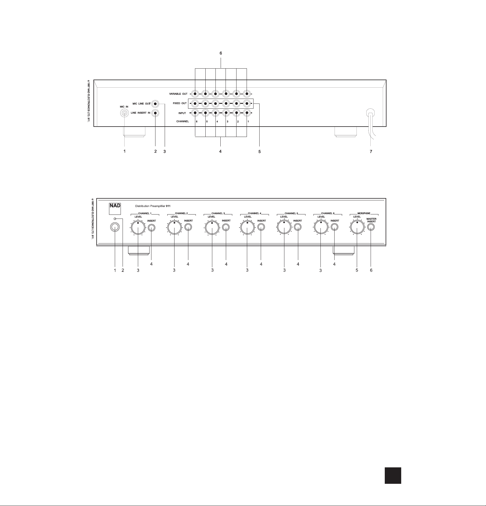
REAR PANEL CONNECTIONS
FRONT PANEL CONTROLS
Page 4

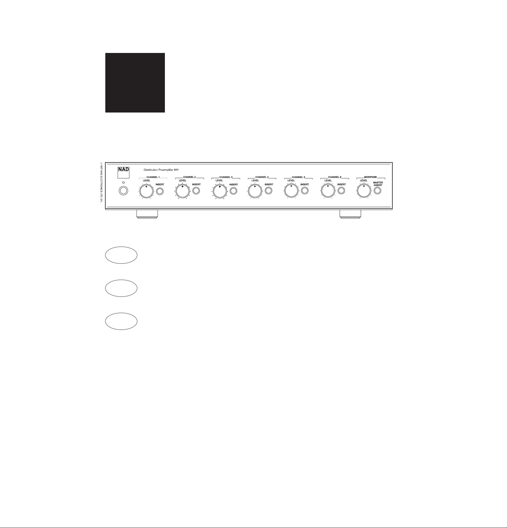
INTRODUCTION TO THE NAD-911 DISTRIBUTION PREAMPLIFIER.
The NAD-911 Distribution Preamplifier has been
designed to control sound in multi-room or multispeaker installations where both music and messaging is required. It will take mono or stereo signals
from a mixer or hi-fi preamplifier and control the distribution of sound in up to six separately controllable
speaker zones. Each level control will alter the volume of one particular speaker zone so that the system can deliver music at different levels in different
areas of the installation. With the built-in microphone
section, the NAD-911 can selectively deliver
announcements and messages to individual parts of
the system.
Several NAD-911s can be connected together to
control music and messages in larger installations.
With a range of internal configuration presets, the
NAD-911 has the flexibility to be configured to match
the needs of most setups.
This manual outlines the use of the NAD-911 in the
most common types of installation. The unit can also
be configured for a wide range of specialist setups
and a qualified installation engineer will be able to
advise on connecting and configuring the NAD-911
within more complex installations.
IMPORTANT INFORMATION.
The NAD- 911 should be placed on a firm level surface. Dampness can damage electronic components,
so the unit should not be placed in areas of high
humidity or where liquid could be splashed on it or
spilt over it.
If liquid is spilt over the unit then disconnect from
the AC socket and have the unit inspected by qualified service personnel before attempting to use it
again.
The NAD-911 uses standard RCA and 1/4” jack
connections and it is recommended that you use high
quality connectors and cables throughout the installation as this will improve the reliability and the overall
performance of the system.
If the unit is not going to be used for some time,
disconnect the power plug from the AC socket.
There are installation presets inside the unit and
these should be adjusted by qualified installation personnel only. Ensure the top cover is securely
replaced before using your NAD Distribution
Preamplifier.
CLEANING.
Use a soft cloth to clean the NAD-911. If necessary, lightly dampen the cloth with soapy water. Do
not use solutions containing benzol or other volatile
agents.
REAR PANEL CONNECTIONS.
1.MIC IN
Input for a Microphone. This Input is suitable for
most medium to high impedance microphones.
The microphone circuitry has a bass roll-off filter
that will reduce low frequency microphone handling
noises being passed to the speakers. A limiter has
been added to the microphone circuit to reduce overload distortion on very loud sounds. The Microphone
is selected by using the front panel MASTER INSERT
button (6) together with the individual channel
INSERT buttons (4) and adjusting MICROPHONE
LEVEL control (5). Plugging in a microphone into this
socket automatically switches off the LINE INSERT
IN connector.
2.LINE INSERT IN
Input for a line level source. This is used as an
alternative to the microphone for message sources
such as pre-recorded announcements. This is only
active when MIC IN is unused. The MIC IN and LINE
INSERT IN signal can be at a fixed or variable level
depending on the settings of the internal configuration
presets.
3.MIC LINE OUT
Direct output for the microphone signal. The NAD911 amplifies the microphone input to line level so it
can be used as the microphone feed to additional
NAD-911s in a larger installation. The output of this
socket can be at a fixed or variable level depending
on the settings of the internal configuration presets.
4.INPUT (CHANNELS 1 -6)
Line level inputs for each of the six channels.
These can be connected to any type of audio system
such as a hi-fi preamplifier, cassette deck, CD player,
mixer or the audio outputs of a video player. For
mono sources use a single channel, for stereo
sources use two adjacent channels.
5.FIXED OUT (CHANNELS 1-6)
Direct output for each channel. The level of the
signal on this connector remains the same regardless
of the front panel level controls. The INSERT signal
does not appear on the FIXED OUT connections. The
level is suitable for driving standard hi-fi components
and amplifiers and can be used with leads up to 1nF
total capacitance.
6.VARIABLE OUT (CHANNELS 1-6)
Direct output for each channel. The level of the
signal on this connector is altered by the front panel
LEVEL controls (5). The INSERT signal will appear
mixed on the VARIABLE OUT connections when
selected by pressing the INSERT buttons. At its higher settings of the LEVEL control, this output will drive
professional (20dBu/600ohm) amplifiers. The variable
output has a low impedance so it can be used to
drive long cable runs up to 22nF total capacitance.
7.POWER CABLE
Fixed power AC cord for connection to AC socket.
NA
D
4
GB
NAD 911 DISTRIBUTION PREAMPLIFIER
Page 5
GB
FRONT PANEL CONTROLS.
1.POWER
Power switch to turn the NAD-911 on or off.
2.POWER LED
Indicates that the unit is on.
CHANNELS 1 - 6.
3.LEVEL
Adjusts the volume of each individual speaker
channel.
4. INSERT
Allows the Insert Signal (MIC IN or LINE INSERT
IN) to be included on this particular speaker channel
MICROPHONE.
5.LEVEL
Adjusts the overall volume of the Insert signal from
the MIC IN or LINE INSERT IN sockets.
6.MASTER INSERT
Press to switch the Insert signal on. Press out to
completely disable the Insert signal on all channels.
PREAMPLIFIERS, AMPLIFIERS AND
MIXERS FOR USE WITH THE NAD-911.
In most installations using the NAD-911, the hi-fi
preamplifier is used to select the appropriate music
source and for every-day adjustment of the music volume in the venue.
Any hi-fi preamplifier can be used with the NAD911 or alternatively an integrated hi-fi amplifier can be
used providing it has a ‘pre-amp’ output. NAD supplies a range of preamplifiers and integrated amplifiers suitable for use with the NAD-911.
Some installations will use a mixer instead of a preamp and this is connected and used with the NAD911 in exactly the same way as a preamplifier.
The channel outputs of the NAD-911 will work with
both hi-fi and professional power amplifiers. There is
a range of NAD single channel, stereo or multi-channel power amplifiers that are suitable to work with the
NAD-911.
You should ensure that the power output level of
the power amplifiers used in the installation matches
the capabilities of the loudspeakers. If you are using
a power amplifier with its own volume control, during
installation set the NAD-911 LEVEL controls (3) to
the 12 O’clock position and then adjust the power
amplifier’s volume control so that the sound level
from the speaker is about right for normal use.
CABLES.
The amplifiers can be placed near the NAD-911
using short signal leads and long speaker leads.
Generally you will get better performance from the
installation if the amplifiers are placed nearer the
speakers using longer signal leads and shorter
speaker leads. In either case to achieve best performance all speaker cables should be high quality large
diameter speaker cables (16 gauge or more) and all
signal leads should be high quality co-axial cable.
Cable lengths of up to 22nF total capacitance can
be used to connect the NAD-911 Variable Output to
an amplifier.
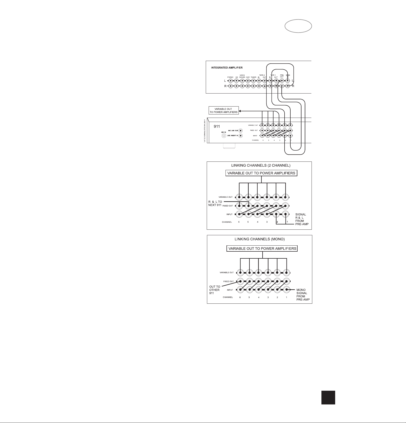
CONNECTING INPUTS.
A simple installation uses a CD player and
Cassette Deck connected to the hi-fi preamplifier. In a
stereo system the hi-fi preamplifier is connected to
INPUT sockets (4) of Channels 1 & 2 of the NAD-
911. In a mono system connect the preamplifier to
the INPUT of Channel 1 only.
Connect the Microphone to the MIC IN (1).
LINKING CHANNELS.
Feeding the music signal to every channel in the
distribution preamplifier is done by using links
between the outputs of each channel to the inputs of
the other channels.
NA
D
5
Page 6
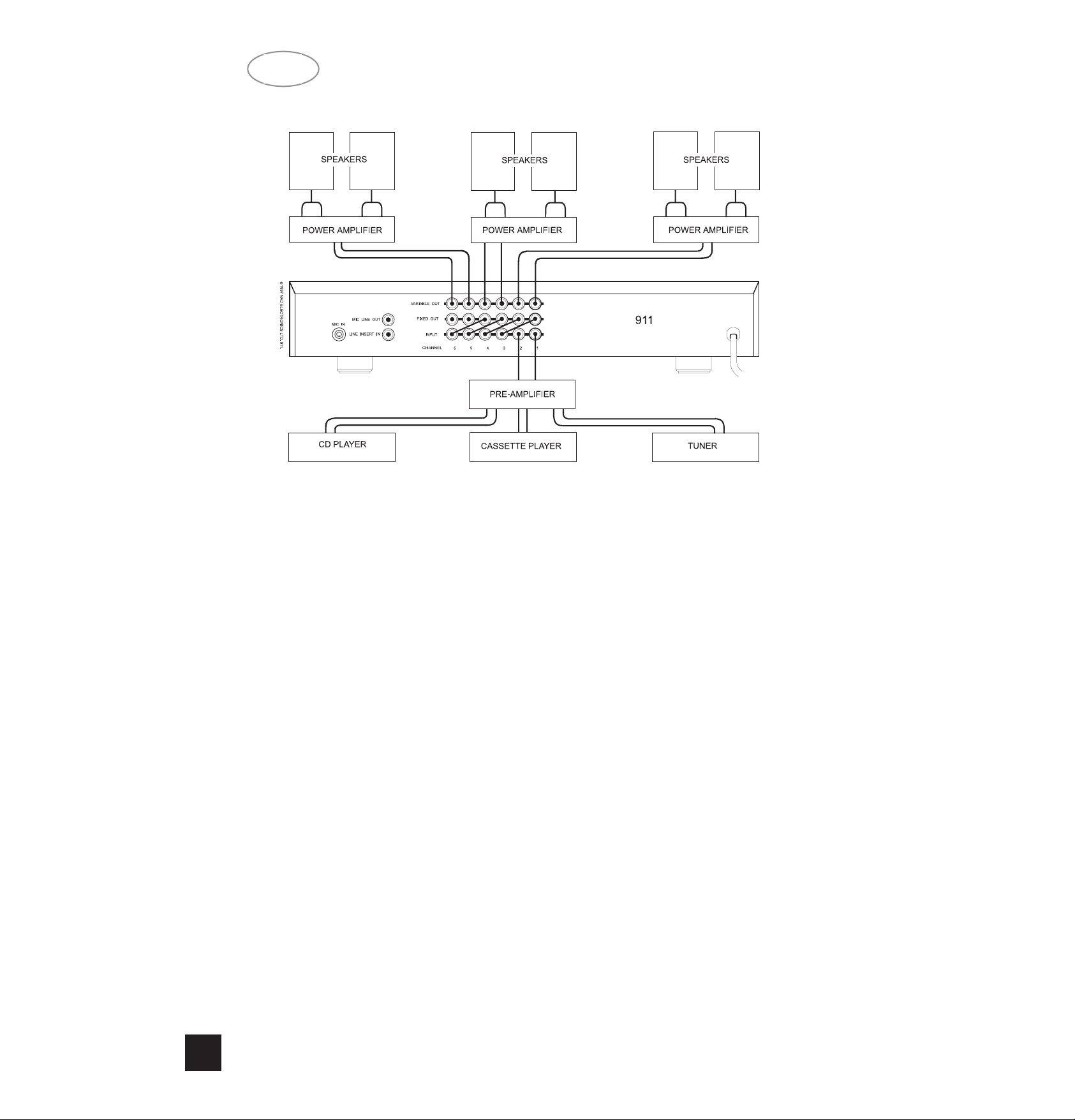
Using the short RCA leads supplied, connect the
FIXED OUTPUT (5) of Channels 1 and 2 to the
INPUT (4) of Channels 3 & 4. Then connect the
FIXED OUTPUT of Channels 3 & 4 to the INPUTs of
Channels 5 & 6. (In a mono system connect Channel
1 FIXED OUTPUT to Channel 2 INPUT etc.)
CONNECTING OUTPUTS.
Connect the VARIABLE OUT sockets (6) of each
channel to the appropriate power amplifier and
speaker system. The power amplifiers and loudspeakers should be matched with respect to power
and quality. NAD supplies a range of power and integrated amplifiers suitable for use in these types of
installations.
SETTING THE MUSIC LEVEL.
Set the hi-fi preamplifier volume control to minimum. Set the NAD-911 MICROPHONE LEVEL control (5) to minimum and the rest of the Channel
LEVEL controls (3) to the 12 O’clock position. Switch
the system on.
With a music source playing (preferably a CD) turn
the preamplifier volume control up until the music
reaches a generally acceptable level. Now adjust
each of the individual speaker volumes to exactly the
required level by adjusting each of the NAD-911
channel LEVEL controls (3).
SETTING THE MICROPHONE LEVEL.
Switch off the music source. Set the MICROPHONE LEVEL control (5) to minimum. Press the
MICROPHONE MASTER INSERT button (6) in and
the INSERT buttons (4) on all channels. Speak into
the microphone whilst slowly turning up the MICROPHONE LEVEL control (5) until the announcement
level is about right. Switch the music source on and
fine adjust the MICROPHONE LEVEL. Switch out the
MICROPHONE MASTER INSERT button when finished.
BASIC OPERATION.
The NAD-911 is used primarily as an installation
tool to distribute and accurately set up the sound levels in all parts of the venue. So in general daily operation, adjust the music source and overall level using
the hi-fi preamplifier controls only.
INSERT SIGNAL TO ALL CHANNELS
In a simple installation, where all the channels are
linked together, press the INSERT (4) button on all
channels. Announcements will be fed to all speakers
whenever the microphone is used and the MASTER
INSERT button is pressed.
INSERT SIGNAL ONLY ON SELECTED
CHANNELS
Press the INSERT buttons (4) only on the channels
where announcements are required. Announcements
will be fed to those speakers whenever the microphone is used and the MASTER INSERT button is
pressed.
Only the channels with the INSERT buttons
depressed will be fed with the announcements when
the microphone is used and the MASTER INSERT
button is pressed. If announcements are to be fed
only to specific channels then press the INSERT (4)
buttons on only those channels which need
announcements.
NOTE:
The microphone Insert signal can be configured
internally to be disabled, inserted before or after
either one of the six channel level controls. The factory default setting inserts the signal before the level
control for all channels. Changing the configuration
must be left to qualified personnel.
USING MIC LINE OUT
As well as feeding the Microphone signal internally
to each channel using the Insert function, there is a
NA
D
6
GB
BASIC CONNECTION AND OPERATION.
Page 7
GB
NA
D
7
separate microphone signal output, the MIC LINE
OUT (3).
This output carries the microphone signal amplified
to line level. It can be used to feed the microphone
signal to further external units such as a second
NAD-911 or to link in with other separate sound
installations.
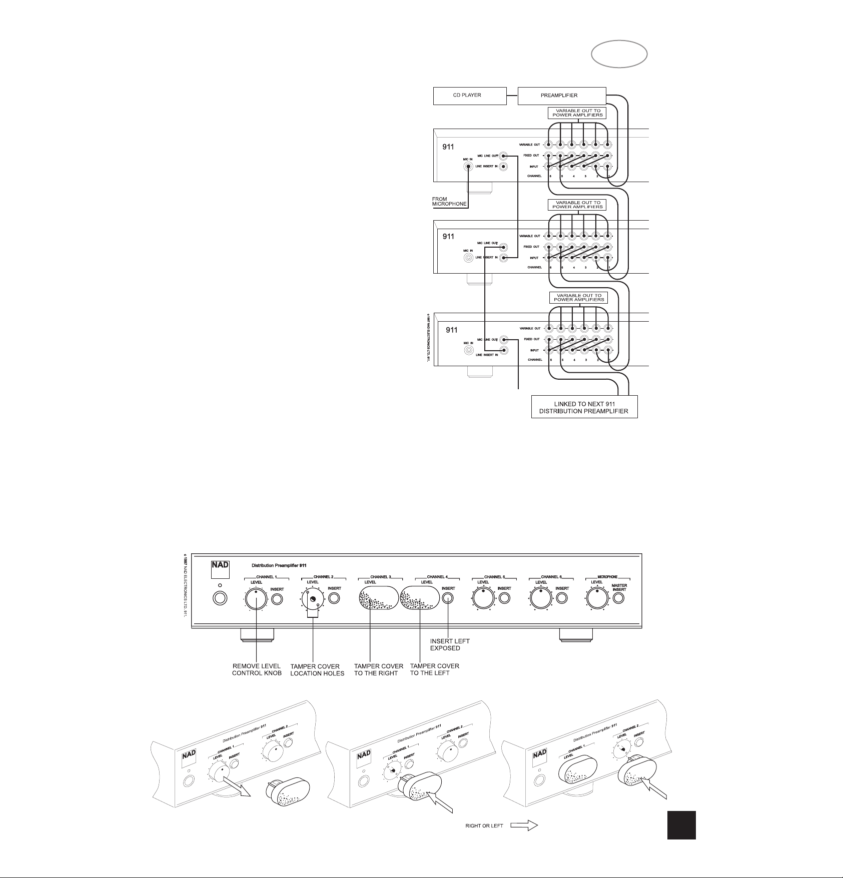
USING SEVERAL NAD-911s.
The outputs of the main distribution preamplifier are
connected to the first channels of the second unit to
feed it with the music signal.
Use the main NAD-911’s MIC LINE OUT (3) to
send the microphone insert signal to the second
unit’s LINE INSERT IN (2) socket. This will ensure
you maintain full control over which speaker channels
get fed with the announcements and at what level.
NOTE: In the factory default setting, the Mic Line
Out signal level is linked with the Microphone Level
control (5) on the front panel. The NAD 911 configuration can be changed so that the Mic Line Out signal
level is fixed, independent from the Microphone Level
Control. Changing the configuration must be left to
qualified personnel.
TAMPER-PROOF COVERS.
If the system is to be installed so that its level settings do not need to be changed in normal operation,
then use the Tamper-proof Covers included with your
NAD-911 to stop accidental use of the LEVEL controls and/or INSERT buttons. Fitting it with the Insert
Button section of the cover to the right, will protect
both the level settings and the insert button settings.
Using the cover with the insert button section to the
left leaves the insert button available.
Remove the volume control on any channels that
need tamper-proofing, by gently pulling the LEVEL
knob off its spindle.
Gently push the Tamper-proof Cover in the opening
left by the volume control knob. Ensure that the two
small legs on the Tamper-proof cover line up with the
two holes in the sub-facia behind the front panel.
Page 8

SERVICING, INSTALLATION AND CONFIGURATION INTRUCTIONS
CAUTION:
These servicing and installation
instructions are for use by qualified personnel
only. To reduce the risk of electric shock do not perform any servicing other than that contained in the
operation instructions unless you are qualified to do
so. Refer all servicing to qualified service person-
nel.
CAUTION: Before removing the top cover dis-
connect the unit from the mains supply.
INSERT SYSTEM CONFIGURATION.
Altering jumpers inside the unit can change the
way the insert and variable level functions work so
that the NAD-911 can be configured to meet the
messaging requirements of the system. This must
be done by qualified personnel only.
WHY USE DIFFERENT INSERT SETTINGS?
Whilst the basic function of accurately setting the
music levels to individual speakers is generally the
same in all installations, the announcement requirements may vary enormously. The Insert configuration allows installers to match the operation of the
NAD-911 exactly to the announcement needs of the
user.
MICROPHONE LINE OUT LEVEL, FIXED OR
VARIABLE.
If the system is being used in an area where the
music level needs to be varied as the background
noise varies,then the announcement levels should
also go up or down with the music level. This
ensures that the announcements will be heard over
the music and general background noise in the area.
In this situation the insert function of each channel
should be set to Insert Variable.
If the system is being used in an office or shop
type of venue where the music level is only occasionaly altered and set to low background level, then
the Microphone level needs to be set up so that
announcements can be heard clearly but are not too
loud. Setting all channels to Insert Fixed helps to
ensure that the correct announcement levels are
maintained.
Some areas of the installation may never need
announcements. Configure the channels feeding the
speakers in these areas to Insert Disabled to ensure
that announcements are not accidentally routed to
these areas.
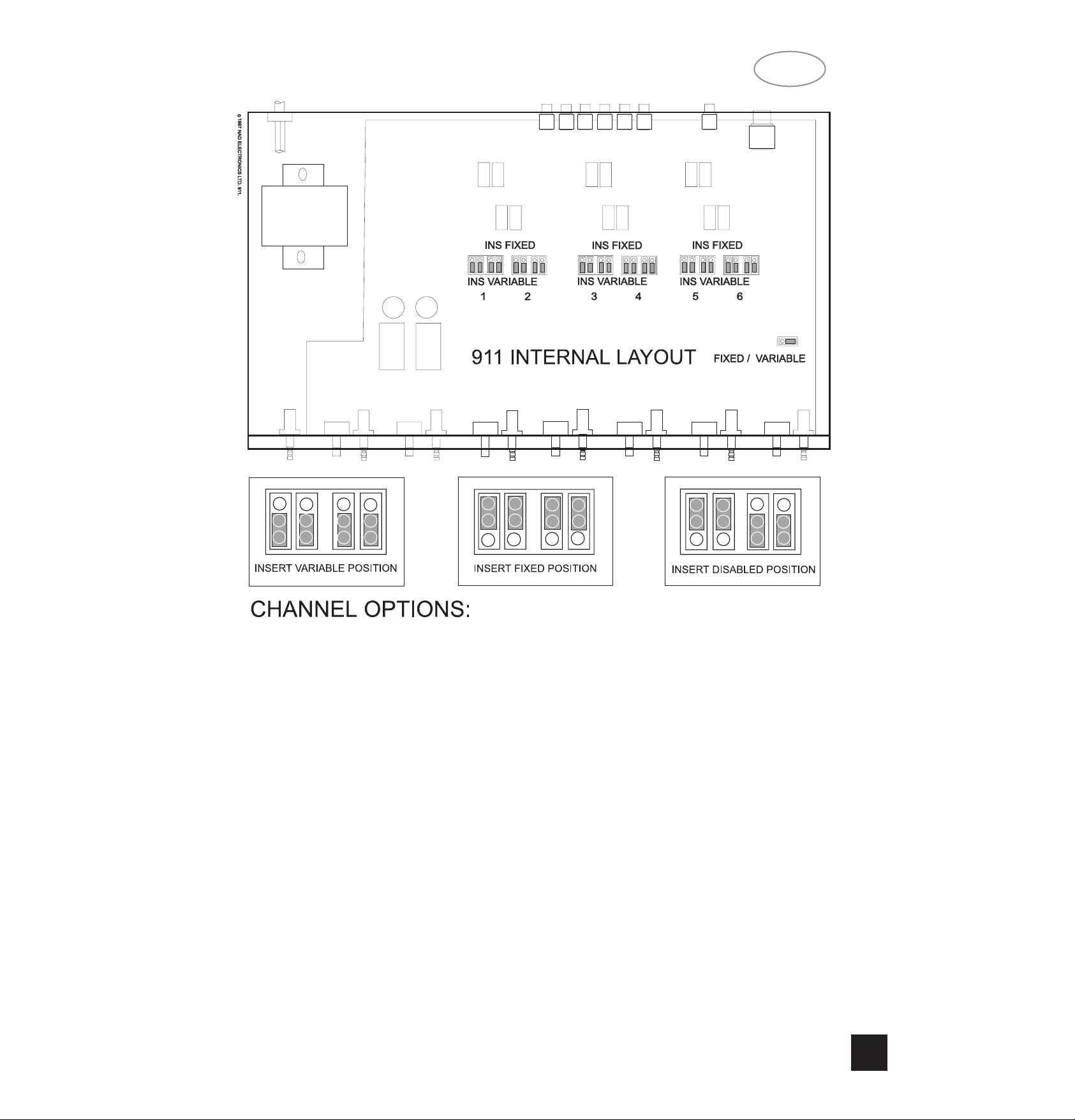
CONFIGURING THE NAD-911 INTERNAL
JUMPERS.
With the unit unplugged from the AC socket,
remove the lid by removing the 5 screws securing
the top panel. When the 911 has been configured
securely replace the unit’s top panel.
FIXED OR VARIABLE MICROPHONE LINE
OUT LEVEL.
In most installations using multiple NAD 911, it will
be desirable to give the first 911 control over the
microphone level for all 911s in the system. In this
case the first 911 should be set to Variable and all
following 911s should be set to Fixed. This way the
second and subsequent 911s will not alter the
Microphone Line out level to the next 911.
Change jumper JP25 from the factory default setting ‘VARIABLE’ to the ‘FIXED’ position.
CONFIGURING MICROPHONE AND MUSIC
LEVELS.
Each channel can be configured individually so
that the Microphone or Line Insert volume level will
always be the same regardless of the individual
channels level setting. Alternatively the channel can
be configured so that the Microphone level is linked
to the level of the music. Turning up the channel’s
level control will then also turn up the volume of the
microphone.
A third setting switches off the microphone signal
from that channel completely.
NOTE: For all channels the factory default is set to
Variable.
FIXED MICROPHONE LEVEL.
To set up the channel so that the level of the
Inserted signal (Microphone or pre-recorded message) to be at a preset level no matter what the individual channel volume setting is.
Set the four jumpers for that channel to INS
FIXED.
LINKING MICROPHONE AND INPUT
LEVELS.
To set up the channel so that the channel level
control alters the volume of both the music and insert
levels. Set the four Jumpers for that channel to INS
VARIABLE.
DISABLING MICROPHONE INSERT ON A
CHANNEL.
If you don’t want the Insert signal to ever appear
on a particular channel. Set the channel’s first two
jumpers (JP -01 and JP -02) to INS FIXED and set
the second two jumpers (JP -03 and JP -04) to INS
VARIABLE
CAUTION: Do not use any other configuration of
the jumpers.
NA
D
8
GB
Page 9
GB
NA
D
9
CONFIGURATION SETTINGS.
Use this table to keep a note of the NAD-911 set-
tings.
NAD 911 Ser. no:
Unit location...................................
Date..................
Channel 1: Variable ___ Fixed ___ Disable ___
Channel 2: Variable ___ Fixed ___ Disable ___
Channel 3: Variable ___ Fixed ___ Disable ___
Channel 4: Variable ___ Fixed ___ Disable ___
Channel 5: Variable ___ Fixed ___ Disable ___
Channel 6: Variable ___ Fixed ___ Disable ___
Microphone Line Out: ___ Variable Fixed ___
Page 10

NA
D
10
GB
TROUBLESHOOTING.
NO SOUND.
AC cord unplugged or power not switched on. Check AC socket, lead and fuse if fitted.
Output lead not properly connected or damaged. Check the connections at both ends (NAD-911
and power amplifier).
Amplifier not switched on, level controls too low or Check amplifier, connections and settings
amplifier faulty.
Speakers not properly connected or damaged Check connections and speakers.
Internal fuse blown Consult dealer
NO SOUND ONE CHANNEL.
Level controls set too low. Adjust level control.
Wrong channel being adjusted. Check all channel level controls
NO LINE LEVEL INSERT SIGNAL.
Microphone connected. Disconnect microphone
Input leads not properly connected or damaged Check connections.
Source system not producing signal. Check output of source system.
NO MICROPHONE SIGNAL OR FEEDBACK.
Microphone leads not properly connected or damaged Check connections.
Microphone not switched on. Switch microphone on or to ‘Talk’
Microphone battery flat. Check or replace microphone battery if used.
Microphone requires ‘phantom’ powering. Consult your microphone supplier for a suitable
adapter.
Loud High Pitch sound when the Microphone is switched on. Feedback caused by the microphone being too
close to a speaker. Move the speaker or micro
phone position or use the configuration jumpers
to disable the Insert
Feed to that particular speaker.
Page 11

F
NA
D
11
Le Préamplificateur de Distribution NAD-911 a été
conçu pour gérer la sonorisation sur les installations
multisalles ou multi-pièces où il est nécessaire de
diffuser aussi bien de la musique que des messages.
Il accepte des signaux monophoniques ou stéréophoniques provenant d’un mélangeur ou d’un préamplificateur hi-fi et en gère la distribution vers un maximum de six zones desservies par des haut-parleurs,
réglables individuellement. Chaque commande de
niveau permet de régler le niveau sonore d’une zone
spécifique, afin que le dispositif soit capable diffuser
de la musique à des niveaux sonores différents dans
différents endroits de l’installation. Grâce à la section
microphone incorporée, le NAD-911 est capable
d’émettre des annonces vocales et des messages
aux différentes zones de l’installation, et ce de façon
sélective.
Pour gérer la musique et les messages sur des
installations de plus grande taille, il est possible de
relier plusieurs NAD-911 ensemble. Grâce à une
gamme de préréglages internes, le NAD-911 est
suffisamment flexible pour être configuré suivant les
exigences de la plupart des installations.
Ce manuel donne une description générale de
l’utilisation du NAD-911 dans la plupart des installations typiques. Le dispositif peut aussi être configuré
pour de nombreuses installations spécialisées,
auquel cas un technicien d’installation qualifié pourra
fournir les informations nécessaires au branchement
et à la configuration du NAD-911 au sein d’installations plus complexes.
INFORMATIONS IMPORTANTES.
Le NAD-911 doit être posé sur une surface plane
et rigide. L’humidité peut endommager les composants électroniques : éviter de placer l’ensemble
dans un endroit très humide ou dans un lieu où il
risque d’être éclaboussé par un liquide.
En cas d’éclaboussure ou de déversement de liquide sur l’appareil, débrancher celui-ci et le faire contrôler par un personnel de service après vente qualifié, avant de le réutiliser.
Le NAD-911 utilise des connecteurs jack 1/4” RCA
standards ; il est recommandé d’utiliser des connecteurs et des câbles de qualité supérieure dans
l’ensemble de l’installation, car cette précaution rendra les performances globales du système plus
fiables.
Si l’appareil doit rester inutilisé pendant un certain
temps, débrancher le câble d’alimentation de la prise
secteur.
Des dispositifs de préréglage d’installation sont
prévus à l’intérieur de l’appareil, et ne doivent être
réglés que par un personnel d’installation qualifié.
Veiller à bien remettre et fixer le couvercle supérieur
avant d’utiliser votre Préamplificateur de Distribution
NAD.
NETTOYAGE.
Nettoyer le NAD-911 avec un chiffon propre. Si
nécessaire, humecter le chiffon avec de l’eau savonneuse. Ne pas utiliser de solution contenant du benzol ou un autre agent volatile.
BRANCHEMENTS SUR LE PANNEAU
ARRIERE.
1. ENTREE MICRO [MIC IN]
Entrée pour un Microphone. Cette entrée convient
à la plupart des microphones moyenne ou haute
impédance.
Le circuit microphone comporte un filtre éliminateur de basses fréquences permettant d’éviter la
transmission, jusqu’aux haut-parleurs, des bruits de
manipulation du microphone. Un limiteur a aussi été
incorporé au circuit microphone afin de réduire la
distorsion de surcharge dans les sons très forts. La
sélection du Microphone se fait à l’aide du bouton
d’INSERTION GLOBALE [MASTER INSERT] (6) de
la face parlante et des boutons d’INSERTION
[INSERT] (4) des voies individuelles, et en réglant la
commande de NIVEAU MICROPHONE [MICROPHONE LEVEL] (5). Le fait de brancher un microphone sur cette prise désactive automatiquement le
connecteur d’ENTREE INSERTION LIGNE [LINE
INSERT IN].
2. ENTREE D’INSERTION LIGNE [LINE
INSERT IN]
Entrée prévue pour une source de niveau ligne.
Cette entrée est utilisée en alternative à l’entrée
microphone, pour diffuser des sources de messages
comme les annonces préenregistrées. Cette entrée
n’est active que lorsque l’ENTREE MICRO [MIC IN]
n’est pas utilisée. Le signal ENTREE MICRO [MIC
IN] et ENTREE INSERTION LIGNE [LINE INSERT
IN] peut être de niveau fixe ou variable, en fonction
des préréglages de configuration internes.
3.SORTIE LIGNE MICRO [MIC LINE OUT]
Sortie directe du signal microphone. Le NAD-911
amplifie l’entrée microphone jusqu’au niveau ligne,
de manière à ce qu’il puisse être utilisé comme signal microphone pour d’autres NAD-911 dans une
installation de plus grande taille. La sortie de ce connecteur peut être de niveau fixe ou variable, en fonction des préréglages de configuration internes.
4. ENTREE [INPUT] (VOIES 1 à 6)
Entrées de niveau ligne pour chacune des six
voies. Ces entrées peuvent être reliées à n’importe
quel système audio comme par exemple un préamplificateur hi-fi, une platine à cassettes, un lecteur
CD, un mélangeur ou les sorties audio d’un lecteur
vidéo. Pour les sources monophoniques, utiliser une
seule voie ; pour les sources stéréophoniques, utiliser deux voies adjacentes.
5. SORTIE FIXE [FIXED OUT] (VOIES 1 à 6)
Sortie directe pour chaque voie. Le niveau du signal sur ce connecteur reste le même quel que soit le
réglage des commandes de la face parlante. Le signal d’INSERTION [INSERT] n’est pas présent sur les
connecteurs de SORTIE FIXE. Ce niveau est adapté
au pilotage des amplificateurs et modules hi-fi standards ; la sortie est utilisable avec des câbles dont la
capacité totale peut atteindre 1 nF.
PREAMPLIFICATEUR DE DISTRIBUTION
NAD-911.
Page 12

6. SORTIE VARIABLE [VARIABLE OUT]
(VOIES 1 à 6)
Sortie directe pour chaque voie. Le niveau du signal sur ce connecteur est modifiable à l’aide des
commandes de NIVEAU [LEVEL] (5) de la face parlante. Le signal d’INSERTION [INSERT] parvient aux
connecteurs de SORTIE VARIABLE sous forme
mélangée s’il est sélectionné en appuyant sur les
boutons d’INSERTION. Lorsque la commande de
NIVEAU [LEVEL] est réglée dans sa plage
supérieure, cette sortie est capable de piloter les
amplificateurs professionnels (20 dBu / 600 ohm). La
sortie variable est de faible impédance et peut donc
être utilisée pour piloter des câbles de longueur
importante dont la capacité totale peut aller jusqu’à
22 nF.
7. CABLE D’ALIMENTATION
Câble d’alimentation secteur pour connexion à une
prise de secteur.
COMMANDES SUR LA FACE PARLANTE.
1. ALIMENTATION [POWER]
Interrupteur d’alimentation permettant de mettre le
NAD-911 sous/hors tension.
2. TEMOIN (LED) D’ALIMENTATION
Cette diode électroluminescente indique que
l’appareil est sous tension.
VOIES [CHANNELS] 1 à 6.
3. NIVEAU [LEVEL]
Règle individuellement le niveau sonore de chaque
voie.
4. INSERT [INSERTION]
Permet d’insérer le Signal d’Insertion (ENTREE
MICRO ou ENTREE INSERTION LIGNE) spécifiquement sur cette voie de haut-parleurs.
MICROPHONE.
5. NIVEAU [LEVEL]
Règle le volume global du signal d’Insertion
provenant des connecteurs d’ENTREE MICRO [MIC
IN] ou d’ENTREE INSERTION LIGNE [LINE INSERT
IN].
6. INSERTION GLOBALE [MASTER INSERT]
Appuyer sur ce bouton-poussoir pour activer le signal d’Insertion. Réappuyer (bouton sorti) pour désactiver totalement le signal d’Insertion sur toutes les
voies.
PREAMPLIFICATEURS, AMPLIFICATEURS ET MELANGEURS A UTILISER
AVEC LE NAD-911.
Sur la plupart des installations mettant en oeuvre le
NAD-911, le préamplificateur hi-fi est utilisé pour
sélectionner la source musicale appropriée et pour
effectuer le réglage courant du volume sonore de la
musique d’ambiance sur le site.
Il est possible d’utiliser n’importe quel préamplificateur hi-fi avec le NAD-911 ; on peut même utiliser un
amplificateur-préamplificateur hi-fi intégré, à condition
qu’il dispose d’une sortie “préampli”. NAD propose
une gamme de préamplificateurs et d’amplificateurspréamplificateurs intégrés parfaitement adaptés à
une utilisation avec le NAD-911.
Certaines installations utilisent un mélangeur au
lieu d’un préamplificateur. Un mélangeur se branche
et s’utilise avec le NAD-911 exactement de la même
façon qu’un préamplificateur.
Les sorties des différentes voies du NAD-911 fonctionnent aussi bien avec des amplificateurs hi-fi
qu’avec des amplificateurs professionnels. NAD propose une gamme d’amplificateurs mono-voies,
stéréophoniques ou multi-voies parfaitement adaptés
à une utilisation avec le NAD-911.
NA
D
12
F
Page 13

F
NA
D
13
Veiller à ce que la puissance de sortie des amplificateurs de puissance utilisés sur l’installation corresponde bien aux capacités des haut-parleurs. Si
l’amplificateur de puissance utilisé comporte sa propre commande de volume sonore, régler les commandes de NIVEAU [LEVEL] (3) du NAD-911 en
position médiane puis régler la commande de volume
de l’amplificateur de puissance pour obtenir un
niveau sonore à peu près correct pour une exploitation normale.
CABLES.
Il est possible de placer les amplificateurs à proximité du NAD-911 en utilisant des câbles de signaux
courts et des câbles de haut-parleurs longs.
Cependant, les performances de l’installation seront
généralement meilleures si les amplificateurs se trouvent plus près des haut parleurs ; dans ce cas, les
câbles des signaux sont plus longs et les câbles des
haut-parleurs sont plus courts. Dans un cas comme
dans l’autre, les meilleures performances seront
obtenues en utilisant des câbles de haut-parleurs de
qualité supérieure et de grand diamètre (calibre 16
minimum) et des câbles de signaux coaxiaux de qualité supérieure.
La longueur des câbles utilisés pour relier la Sortie
Variable du NAD-911 à un amplificateur est limitée
par une capacité totale de 22 nF maximum.
BRANCHEMENT DES ENTREES.
Une installation simple comporte un lecteur de CD
et une Platine à Cassettes reliés au préamplificateur
hi-fi. Dans le cas d’une installation stéréophonique, le
préamplificateur est relié aux connecteurs d’ENTREE
[INPUT] (4) des Voies 1 & 2 du NAD-911. Dans le
cas d’une installation monophonique, relier le préamplificateur à l’ENTREE de la Voie 1 uniquement.
Brancher le Microphone sur le connecteur
d’ENTREE MICRO [MIC IN] (1).
INTERCONNEXION DES VOIES
Pour envoyer le signal musical à toutes les voies
du préamplificateur de distribution, les sorties de
chaque voie sont reliées aux entrées des autres
voies.
A l’aide des câbles phono RCA fournis, relier la
SORTIE FIXE [FIXED OUTPUT] (5) des Voies 1 et 2
à l’ENTREE [INPUT] (4) des Voies 3 et 4. Relier
ensuite la SORTIE FIXE des Voies 3 et 4 aux
ENTREEs des Voies 5 et 6. (Dans le cas d’une installation monophonique, relier la SORTIE FIXE de la
Voie 1 à l’ENTREE de la Voie 2, etc ...).
CONNEXION DES SORTIES.
Relier les connecteurs de SORTIE VARIABLE
[VARIABLE OUT] (6) de chaque voie à la voie
amplificateur / haut-parleurs appropriée. Les amplificateurs de puissance et les haut-parleurs correspondants doivent être appariés aussi bien du point de
vue de leur qualité que de celui de leur puissance.
NAD propose une gamme de préamplificateurs et
d’amplificateurs-préamplificateurs intégrés parfaitement adaptés à une utilisation avec ce type d’installation.
CONNEXION ET FONCTIONNEMENT DE BASE.
Page 14

NA
D
14
F
REGLAGE DU NIVEAU SONORE DE LA
MUSIQUE D’AMBIANCE.
Régler la commande de volume sonore du préamplificateur hi-fi au minimum. Régler la commande de
NIVEAU MICROPHONE [MICROPHONE LEVEL] (5)
du NAD-911 au minimum et les autres commandes
de NIVEAU [LEVEL] (3) des différentes voies en
position médiane. Mettre l’installation sous tension.
Après avoir mis en marche une source musicale
(un CD de préférence), augmenter le volume sonore
à l’aide de la commande du préamplificateur jusqu’à
ce que la musique atteigne un niveau acceptable.
Régler ensuite le volume sonore de chaque haut-parleur individuel au niveau précis souhaité, en ajustant
la commande de NIVEAU [LEVEL] (3) de chaque
voie sur le NAD-911.
REGLAGE DU NIVEAU DU MICROPHONE.
Arrêter la source musicale. Régler la commande de
NIVEAU MICROPHONE [MICROPHONE LEVEL] (5)
au minimum. Appuyer sur le bouton-poussoir
d’INSERTION GLOBALE MICROPHONE [MICROPHONE MASTER INSERT] (6) ainsi que sur les boutons-poussoirs d’INSERTION [INSERT] (4) de toutes
les voies. Parler dans le microphone en augmentant
progressivement le réglage de la commande de
NIVEAU MICROPHONE [MICROPHONE LEVEL] (5)
jusqu’à ce que le niveau de l’annonce soit à peu près
correct. Mettre la source musicale en marche et
effectuer le réglage fin du NIVEAU MICROPHONE.
Une fois le réglage terminé, réappuyer sur le boutonpoussoir d’INSERTION GLOBALE MICROPHONE
(bouton sorti).
FONCTIONNEMENT DE BASE.
Le NAD911 s’utilise avant tout en tant qu’outil
d’installation pour assurer la distribution et la configuration précise des niveaux sonores dans tous les
endroits du site. Par conséquent, pour le fonctionnement courant, effectuer les réglages de la source
musicale et du niveau sonore général uniquement à
l’aide des commandes du préamplificateur.
INSERTION D’UN SIGNAL DESTINE A
TOUTES LES VOIES
Sur une installation simple, où toutes les voies sont
reliées ensemble, appuyer sur le bouton d’INSERTION [INSERT] (4) de toutes les voies. Les annonces
sont ainsi envoyées à tous les haut parleurs chaque
fois que quelqu’un se sert du microphone en
appuyant sur le bouton-poussoir d’INSERTION
GLOBALE [MASTER INSERT].
INSERTION D’UN SIGNAL DESTINE A CERTAINES VOIES SPECIFIQUES
Appuyer sur le bouton d’INSERTION [INSERT] (4)
des seules voies sur lesquelles les annonces doivent
être diffusées. Les annonces sont ainsi envoyées aux
haut-parleurs des voies concernées chaque fois que
quelqu’un se sert du microphone en appuyant sur le
bouton-poussoir d’INSERTION GLOBALE [MASTER
INSERT].
Seules les voies dont le bouton d’INSERTION
[INSERT] a été enfoncé reçoivent les annonces
chaque fois que quelqu’un se sert du microphone en
appuyant sur le bouton-poussoir d’INSERTION
GLOBALE [MASTER INSERT]. Si des annonces
doivent être envoyées uniquement sur certaines
voies spécifiques, appuyer sur les boutons-poussoirs
d’INSERTION (4) des seules voies devant recevoir
les annonces.
NOTA :Il est possible de configurer le signal
d’Insertion microphone de façon interne ; il peut ainsi
être désactivé ou inséré avant ou après la commande
de niveau sonore de l’une des six voies. Le réglage
par défaut à l’usine insère le signal avant la commande de niveau sonore sur les six voies. Toute
modification de cette configuration doit être effectuée
par un personnel qualifié.
UTILISATION DE LA SORTIE LIGNE MICRO
[MIC LINE OUT]
En plus de la possibilité d’envoyer le signal
Microphone de façon interne à chaque voie, grâce à
la fonction d’Insertion, une sortie distincte du signal
microphone est aussi prévue : il s’agit de la SORTIE LIGNE MICRO [MIC LINE OUT] (3).
Le signal présent sur cette sortie est le signal
microphone, amplifié au niveau ligne. La sortie peut
être utilisée pour envoyer le signal microphone à
d’autres appareils externes, comme par exemple un
deuxième NAD-911, ou pour assurer une liaison avec
d’autres installations de sonorisation distinctes.
UTILISATION DE PLUSIEURS NAD-911.
Les sorties du préamplificateur de distribution principal sont connectées aux premières voies du deuxième préamplificateur de distribution, de manière à lui
transmettre le signal musical.
Utiliser la SORTIE LIGNE MICRO [MIC LINE OUT]
(3) du NAD-911 principal pour envoyer le signal
Page 15

F
NA
D
15
d’insertion microphone au connecteur d’ENTREE
INSERTION LIGNE [LINE INSERT IN] (2) du deuxième NAD-911. Il est possible, grâce à cette configuration, de gérer pleinement le niveau sonore et la
répartition des annonces aux différentes voies.
NOTA : Dans la configuration par défaut établie à
l’usine, le niveau du signal de Sortie Ligne Micro
dépend du réglage de la commande de Niveau
Microphone (5) de la face parlante. Il est possible de
reconfigurer le NAD-911 de manière à ce que le signal de Sortie Ligne Micro soit fixe, quel que soit le
niveau du signal de Sortie Ligne Micro. La modification de la configuration doit être effectuée par un personnel qualifié.
COUVERCLES ANTI-DEREGLAGE.
Si le système doit être installé de manière à ce
qu’aucun réglage ne soit nécessaire en exploitation
normale, il convient de monter les couvercles antidéréglage fournis avec le NAD-911, ce afin de
prévenir tout déréglage involontaire des commandes
de NIVEAU et/ou des boutons d’INSERTION. Le fait
de monter la partie Boutons d’Insertion à droite permet de protéger aussi bien les réglages des niveaux
que la configuration des boutons d’insertion. En
montant la partie Boutons d’Insertion à gauche, le
bouton d’insertion reste accessible.
Retirer la commande de volume sonore de toute
voie nécessitant une protection anti-déréglage ; pour
cela, retirer doucement le bouton de NIVEAU de son
axe.
Enfoncer avec précaution le couvercle antidéréglage dans l’ouverture libérée par le bouton de
la commande de volume sonore. Veiller à ce que les
deux petites pattes du couvercle anti-déréglage
s’alignent avec les deux trous du sous-bandeau derrière la face parlante.
Page 16

NA
D
16
F
INSTRUCTIONS D’ENTRETIEN,
D’INSTALLATION ET DE CONFIGURATION
ATTENTION :Ces instructions d’entretien et
d’installation sont exclusivement destinées à un personnel qualifié. Afin de réduire le risque de choc électrique, ne procéder à aucun entretien autre que celui
décrit dans les instructions d’utilisation, à moins d’être
qualifié pour le faire. Confier tout entretien au personnel de service après vente qualifié.
ATTENTION : Débrancher l’appareil de l’alimenta-
tion secteur avant de déposer le couvercle supérieur.
CONFIGURATION DU SYSTEME D’INSERTION.
Le fait de changer la configuration des cavaliers à
l’intérieur de l’appareil permet de modifier le comportement des fonctions d’insertion et de variation
des niveaux sonores, de manière à configurer le
NAD-911 en fonction des besoins du système en
matière de messagerie. Ce type de modification doit
être entrepris uniquement par un personnel qualifié.
POURQUOI UTILISER DES REGLAGES DIFFERENTS POUR LES INSERTS ?
La fonction principale, qui consiste à régler avec
précision le niveau sonore de la musique d’ambiance
sur les différents haut-parleurs, est sensiblement la
même d’une installation à une autre ; ce n’est pas la
même chose pour la diffusion des annonces, où la
configuration peut varier énormément. La configuration de la fonction d’insertion permet aux installateurs
d’adapter le fonctionnement du NAD-911 exactement
aux besoins de l’utilisateur pour ce qui concerne les
annonces.
NIVEAU DE SORTIE LIGNE MICROPHONE,
FIXE OU VARIABLE.
Si le système est utilisé dans une zone où le niveau
sonore de la musique d’ambiance a constamment
besoin d’être adapté aux variations du bruit ambiant,
il faut que le niveau des annonces varie en fonction
de celui de la musique d’ambiance. De cette manière,
les annonces seront toujours audibles par rapport à la
musique d’ambiance et au bruit de fond général de la
zone. Dans ce cas, la fonction d’insertion de chaque
voie doit être réglée sur Insertion Variable.
Si le système est utilisé dans un lieu de type
bureau ou magasin, où l’on ne modifie que rarement
le niveau sonore de la musique d’ambiance, qui, de
surcroît, est relativement faible, il est nécessaire de
régler le niveau du Microphone de manière à ce que
les annonces soit clairement audibles mais pas trop
fortes. Le fait de régler toutes les voies sur Insertion
Fixe permet de garantir le maintien de niveaux
sonores appropriés.
Certaines zones de l’installation peuvent ne jamais
avoir besoin de recevoir les annonces. Configurer les
voies pilotant les haut parleurs dans ces zones en
mode Insertion Désactivée afin d’éviter que les
annonces y soient diffusées par inadvertance.
CONFIGURATION DES CAVALIERS
INTERNES DU NAD-911.
Après avoir débranché l’appareil de la prise
secteur, déposer le couvercle en dévissant les 5 vis
de fixation du panneau supérieur. Après avoir configuré le NAD-911, reposer et fixer solidement le panneau supérieur de l’appareil.
Se reporter aux options de configuration dans le
tableau ci-dessous.
NIVEAU DE LIGNE MICROPHONE FIXE OU
VARIABLE.
Dans la plupart des installations mettant en oeuvre
plusieurs NAD-911, il est souhaitable de confier au
premier NAD-911 la gestion du niveau micro pour
l’ensemble des NAD-911 du système. Dans ce cas, il
est nécessaire de régler le premier NAD-911 sur
Variable et tous les autres sur Fixe. De cette manière,
ni le deuxième NAD-911 ni les suivants ne pourront
modifier le niveau sonore de la Ligne Micro connectée au NAD-911 suivant.
Retirer le cavalier JP25 de son emplacement par
défaut “VARIABLE” (réglé à l’usine) et l’insérer à la
position “FIXE”.
CONFIGURATION DES NIVEAUX MICROPHONE ET MUSIQUE.
Chaque voie est configurable individuellement, de
manière à ce que le volume sonore d’Insertion Ligne
ou Micro reste toujours le même quel que soit le
réglage de la musique d’ambiance de la voie concernée. Sinon, il est possible de configurer la voie afin
que le niveau Microphone soit asservi au niveau de la
musique d’ambiance. Dans ce cas, le fait d’augmenter le volume sonore sur la voie concernée augmente aussi le niveau du microphone.
Une troisième possibilité permet de couper totalement le signal microphone de la voie concernée.
NOTA : Le réglage par défaut (à l’usine) de toutes
les voies est “Variable”.
NIVEAU MICROPHONE FIXE.
Permet de configurer la voie de manière à ce que le
signal Inséré (Microphone ou message préenregistré)
reste à un niveau prédéfini quel que soit le réglage du
niveau sonore de la voie concernée.
Régler les quatre cavaliers de la voie sur INSERTION FIXE [INS FIXED].
ASSERVISSEMENT DU NIVEAU MICROPHONE AU NIVEAU D’ENTREE.
Permet de configurer la voie de manière à ce que la
commande de niveau sonore de la voie agisse à la
fois sur le niveau de la musique d’ambiance et sur les
niveaux d’insertion. Régler les quatre cavaliers de la
voie sur INSERTION VARIABLE [INS VARIABLE].
Retirer les cavaliers en plastique et les réinsérer en
fonction de la configuration requise.
DESACTIVATION DE L’INSERTION MICROPHONE SUR UNE VOIE.
Page 17

F
Si l’on souhaite que le signal d’Insertion n’apparaisse jamais sur une voie donnée, régler les deux
premiers cavaliers (JP-01 et JP-02) en configuration
INSERTION FIXE [INS FIXED] et les deux cavaliers
suivants (JP-03 et JP-04) en configuration INSERTION VARIABLE [INS VARIABLE].
ATTENTION : Toute autre configuration des cavaliers est à proscrire.
CONFIGURATION UTILISEE.
Utiliser le tableau ci-dessous pour garder une trace
écrite du réglage des fonctions du NAD-911.
NAD-911 N° Série :
Emplacement de l’appareil :
Date :
Voie 1 : Variable ___ Fixe ___ Désactivée ___
Voie 2 : Variable ___ Fixe ___ Désactivée ___
Voie 3 : Variable ___ Fixe ___ Désactivée ___
Voie 4 : Variable ___ Fixe ___ Désactivée ___
Voie 5 : Variable ___ Fixe ___ Désactivée ___
Voie 6 : Variable ___ Fixe ___ Désactivée ___
Sortie Ligne Microphone : Variable ___ Fixe ___
NA
D
17
Page 18

NA
D
18
F
RECHERCHE DES PANNES.
AUCUN SON.
Câble secteur débranché ou installation hors Vérifier la prise secteur, le câble et le fusible (si prévu).
tension.
Câble de sortie mal branché ou endommagé. Vérifier le branchement aux deux extrémités (côté
NAD-911 et côté amplificateur de puissance).
Amplificateur hors tension, commandes de Contrôler l’amplificateur, les branchements et les réglages.
volume sonore réglées à un niveau trop bas
ou amplificateur défectueux.
Câbles des haut-parleurs mal branchés ou Vérifier le branchement correct des haut-parleurs.
détériorés.
Fusible interne fondu. Consulter le revendeur.
PAS DE SON SUR UNE VOIE.
Commandes de volume sonore réglées à un niveau Régler la commande de volume sonore.
trop bas.
La voie réglée n’est pas la voie concernée. Vérifier le réglage du volume sonore sur toutes les voies.
PAS DE SIGNAL D’INSERTION DE NIVEAU LIGNE
Microphone branché. Débrancher le microphone.
Câbles d’entrée mal branchés ou détériorés. Vérifier les branchements.
Le système source ne produit aucun signal. Vérifier la sortie du système source.
AUCUN SIGNAL DU MICROPHONE OU RETOUR LARSEN.
Câbles du microphone mal branchés ou détériorés. Vérifier les branchements.
Microphone non activé. Actionner l’interrupteur du microphone.
Pile du microphone usée. Vérifier et remplacer la pile du microphone, s’il y en a une.
Le microphone nécessite une alimentation Consulter le fournisseur du microphone pour obtenir un
“fantôme”. adaptateur approprié.
Son puissant et aigu lors de l’activation du Effet de Larsen dû au fait que le microphone est trop près
microphone. d’un haut-parleur. Déplacer le haut-parleur ou le
microphone, ou utiliser les cavaliers de configuration pour
désactiver l’Alimentation d’Insertion du haut-parleur
concerné.
Page 19

D
Der NAD-911 Verteilungsvorverstärker wurde derartig entworfen, daß er zur Verwendung in einer
Mehrraum- oder Mehrfachlautsprecheraufstellung
geeignet ist, in der sowohl die Ausstrahlung von
Musik als auch Benachrichtigungen gewünscht werden. Der Verstärker ist in der Lage Mono- und
Stereosignale von einem Mischpult oder einem HiFiVorverstärker aufzunehmen und diese in bis zu sechs
getrennt kontrollierbare Lautsprecherebenen weiterzugeben. Jede einzelne Kontrollebene kann die
Lautstärke einer bestimmten Sprecherzone verändern, so daß das System Musik zu verschiedenen
Ebenen in verschiedenen Installationsbereichen
liefern kann. Der eingebaute Mikrofonverstärker
ermöglicht dem NAD-911 Verteilungsvorverstärker
Bekanntmachungen und Benachrichtigungen zu den
verschiedenen Teilen des Systems weiterzugeben.
Mehrere NAD-911 Verteilungsvorverstärker können
in Reihe geschaltet werden, um so das Musik- und
Durchsageausstrahlung in größeren Installationen zu
kontrollieren. Der NAD-911 Verteilungsvorverstärker
verfügt über eine weite Reihe von
Vorkonfigurationseinstellungen und ist somit für die
meisten Anwendungsmöglichkeiten geschaffen.
Die vorliegende Bedienungsanleitung beschreibt
die Verwendung des NAD-911 in den üblichsten
Anwendungsumgebungen. Die Systemeinheit kann
ebenso zum Betrieb in einer weiten Reihe von
Spezialeinsätzen konfiguriert werden und ein
entsprechend qualifizierter Techniker wird in der Lage
sein, Sie in bezug auf Einsatz und Konfiguration des
NAD-911 in komplexeren Installationen zu beraten.
WICHTIGE INFORMATION
Der NAD-911 Verteilungsvorverstärker sollte auf
einer festen Oberfläche aufgestellt werden.
Feuchtigkeit kann die elektronischen Bauteile
beschädigen, Sie sollten daher das Gerät nicht in
einer Umgebung mit hoher Luftfeuchtigkeit oder in
einer Umgebung in der möglicherweise Flüssigkeit
verspritzt oder über das System verschüttet werden
kann, aufstellen.
Im Falle, daß Flüssigkeit über die Anlage verschüttet wurde, entfernen Sie es von der
Netzstromversorgung und lassen Sie das Gerät von
qualifizierten Servicetechnikern überprüfen, bevor Sie
es erneut zum Einsatz bringen. Die NAD-911 Anlage
verwendet Standard RCA und _”
Verbindungsbuchsen und es wird empfohlen in der
gesamten Installation hochqualitative
Verbindungsstecker und Kabel zu verwenden, da sie
die Zuverlässigkeit und die Gesamtleistung des
Systems verbessern.
Sollte die Anlage für einige Zeit nicht in Betrieb
genommen werden, so entfernen Sie bitte das
Netzkabel von der Steckdose.
Die Anlage verfügt im Innern über
Installationsvoreinstellungen, welche nur durch qualifiziertes Installationspersonal verändert werden sollten. Bitte stellen Sie sicher, daß die entfernte
Gehäuseabdeckung wieder sicher befestigt wurde,
bevor Sie den NAD Verteilungsvorverstärker erneut
einsetzen.
REINIGUNG
Benutzen Sie ein weiches Tuch um die NAD-911
Anlage zu reinigen. Falls nötig feuchten Sie das Tuch
leicht mit einer Seifenlösung an. Benutzen Sie unter
keinen Umständen benzolhaltige Lösungen oder
andere leicht flüchtige, ätherische Lösungen.
RÜCKWANDVERBINDUNGEN
1. MIC IN
Dies ist der Mikrofoneingang. Dieser Eingang ist für
die meisten mittel bis hochempfindlichen Mikrofone
geeignet.
Der Mikrofonschaltkreis hat ein
Bassdämpfungsfilter, der die unteren
Frequenzbereiche des Mikrofons und somit
Nebengeräusche, die an die Lautsprecher weitergeleitet werden reduziert. Des weiteren ist der
Mikrofonschaltkreis mit einem Begrenzer ausgerüstet
um Überladungsverzerrungen bei sehr lauter
Einstellung zu verringern. Wählen Sie das Mikrofon
über die MASTER INSERT Taste (6) an der
Gerätefront zusammen mit der individuellen
Kanalwahl INSERT Taste (4) und betätigen Sie die
MICROPHONE LEVEL Steuerung (5). Wenn Sie ein
Mikrofon in diese Buchse stecken, wird die LINE
INSERT IN Verbindungsbuchse automatisch ausgeschaltet.
2. LINE INSERT IN
Dies ist der Eingang für eine andere
Wiedergabequelle. Sie wird als Alternative zur
Mikrofoneingabe benutzt, wann immer Sie aufgezeichnete Mitteilungen benutzen wollen. Dieser Eingang
ist nur aktiv, wenn der MIC IN Eingang unbenutzt ist.
Das MIC IN und das LINE INSERT IN Eingangssignal
kann je nach den internen
Konfigurationsvoreinstellungen festgesetzt oder variiert werden.
3. MIC LINE OUT
Dies ist der direkte Ausgang für das Mikrofonsignal.
Der NAD-911 verstärkt das Mikrofoneingangssignal
auf eine Linienebene, so daß dieses Signal als eine
Mikrofonspeisung in weitere NAD-911 Anlagen innerhalb einer größeren Installation benutzt werden kann.
Das Ausgangssignal kann je nach den internen
Konfigurationsvoreinstellungen festgesetzt oder variiert werden.
4. INPUT (KANÄLE 1-6)
Linieneingänge für jeden der sechs Kanäle. Diese
können an jede Art von Audiosystem wie z.B. HiFiVorverstärker, Kassettendecks, CD-Spieler,
Mischpulte oder an die Audioausgänge eines
Videowiedergabegerätes angeschlossen werden.
Benutzen Sie bei Monoquellen einen einzelnen Kanal
und bei Stereoquellen zwei nebeneinander liegende
Kanäle.
NA
D
19
NAD-911 VERTEILUNGSVORVERSTÄRKER
Page 20

5. FIXED OUT (KANÄLE 1-6)
Direkter Ausgang für jeden Kanal. Die Signalstärke
an dieser Verbindungsbuchse bleibt unabhängig von
der Einstellung an der Gerätefront immer gleich. Das
INSERT Signal wird an dieser FIXED OUT
Verbindung nicht wiedergegeben. Die Signalstärke
eignet sich zum Betrieb von Standard HiFiBauelementen und Verstärkern und kann mittels
Kabeln mit einer 1nF Gesamtkapazitanz betrieben
werden.
6. VARIABLE OUT (KANÄLE 1-6)
Direkter Ausgang für jeden Kanal. Die Signalstärke
an dieser Verbindungsbuchse kann durch die LEVEL
Steuerung (5) an der Gerätefront verändert werden.
Das INSERT Signal erscheint an der VARIABLE OUT
Verbindung eingemischt, wenn sie durch Pressen der
INSERT Taste gewählt wurde. In seiner höheren
Einstellung an der LEVEL Steuerung, kann dieser
Ausgang professionelle (20dBu/600ohm) Verstärker
betreiben. Diese variable Ausgang hat eine niedrige
Impedanz und kann somit über lange Kabellängen
bis zu einer Gesamtkapazitanz von 22nF benutzt
werden.
7. STROMKABEL
Festverbundenes Wechselstromkabel zur
Verbindung an eine Wechselstrom-Steckdose.
BEDIENUNG AN DER GERÄTEFRONT
1. STROMZUFUHR
Stromeinschaltungsschalter um die NAD-911
Anlage ein- und auszuschalten.
2. STROMLEUCHTDIODENANZEIGE (LED)
Zeigt an, wenn das Gerät eingeschaltet ist.
KANÄLE 1-6
3. LEVEL
Regelt die Lautstärke jedes einzelnen
Lautsprecherkanals.
4. INSERT
Gestattet es, das Insert Signal (MIC IN oder LINE
INSERT IN) auf diesem spezifischen
Lautsprecherkanal miteinzuschließen.
MIKROFON
5. LEVEL
Regelt die Gesamtlautstärke des Insert Signals von
den MIC IN oder LINE INSERT IN
Verbindungsbuchsen.
6. MASTER INSERT
Drücken Sie die Taste ein um das Insert Signal
einzuschalten. Drücken Sie sie erneut, um sie
auszurasten und um somit das Insert Signal auf allen
Kanälen vollständig auszuschalten.
VORVERSTÄRKER, VERSTÄRKER UND MISCHPULTE IM GEBRAUCH MIT DER NAD-911
ANLAGE
In den meisten Installationen, in den Sie die NAD911 Anlage benutzen wird der HiFi-Vorverstärker
dazu verwendet die entsprechende Musikquelle
auszuwählen und die alltägliche Regelung der
Musiklautstärke in der jeweiligen Anwendung zu
NA
D
20
D
BASIS-VERBINDUNG UND BETRIEB
Page 21

D
steuern.
Mit NAD-911 Anlage können Sie jeden Typ von
HiFi-Vorverstärker benutzen oder alternativ können
Sie einen integrierten HiFi-Verstärker benutzen, der
über einen Vorverstärkerausgang (‘preamp’) verfügt.
NAD verfügt über eine Reihe von Vorverstärkern und
integrierten Verstärkern in seinem Lieferangebot, die
mit der NAD-911 Anlage verwendet werden können.
Manche Installationen benutzen ein Mischpult anstatt
eines Vorverstärkers, das mit der NAD-911 Anlage
zusammen genauso verbunden und benutzt wird, wie
ein Vorverstärker.
Die Kanalausgänge der NAD-911 Anlage arbeiten
sowohl mit Hi-Fi- wie auch mit professionellen
Vollverstärkern. Darüber hinaus gibt es eine Reihe
von einkanaligen, Stereo- oder MultikanalVollverstärkern, die sich zum Einsatz mit der NAD911 Anlage eignen.
Sie sollten sicherstellen, daß die Ausgangsstärke
eines in der Installation benutzten Vollverstärkers
dem Leistungsvermögen Ihrer Lautsprecher
entspricht. Sollten Sie einen Vollverstärker mit eigener Lautstärkekontrolle verwenden, dann sollten Sie
die LEVEL Kontrolle der NAD-911 Anlage (3) auf die
12-Uhr-Position einstellen und dann die Lautstärke
des Vollverstärkers so regeln, daß die
Lautstärkeneinstellung für die Lautsprecher bei normaler Verwendung ungefähr richtig ist.
KABEL
Die Verstärker können in unmittelbarer Nähe der
NAD-911 Anlage und unter Verwendung von kurzen
Signalkabeln und langen Lautsprecherkabeln
aufgestellt werden. Im allgemeinen werden Sie von
der Installation eine bessere Leistung erhalten, wenn
die Verstärker näher zu den Lautsprechern stehen
und dabei längere Signalkabel und kürzere
Lautsprecherkabel benutzt werden. Sie werden in
jedem der beiden Fälle eine bessere Leistung der
Lautsprecher erreichen, wenn Sie hochqualitative im
Durchmesser weitere Kabel verwenden (Maß 16 oder
mehr) und alle Signalkabel sollten aus hochqualitativem Koaxialkabel bestehen.
Kabellängen bis zu 22nF Gesamtkapazitanz können bei der Verbindung des Variablen Ausgangs der
NAD-911 Anlage mit einem Verstärker benutzt werden.
VERBINDUNG DER EINGÄNGE
Eine einfache Installation benutzt einen CD-Spieler
und ein Kassettendeck, die mit einem HiFiVorverstärker verbunden sind. In einer Stereoanlage
ist der HiFi-Vorverstärker mit den INPUT
Verbindungssockeln (4) der Kanäle 1 & 2 der NAD911 Anlage verbunden. In einem Monosystemaufbau
ist der Vorverstärker lediglich über den Kanal 1 mit
der INPUT Buchse verbunden.
Verbinden Sie das Mikrofon mit der MIC IN (1)
Buchse.
DIE VERBINDUNG VON KANÄLEN
Die Speisung des Musiksignals zu jedem Kanal im
Verteilungsvorverstärker wird erreicht, indem die
Verbindungen der Ausgänge eines jeden Kanals mit
den Eingängen der anderen Kanäle verbunden werden. Verwenden Sie die mitgelieferten RCA Kabel
und verbinden Sie den FIXED OUTPUT (5) der
Kanäle 1 & 2 mit dem INPUT (4) der Kanäle 3 & 4.
Verbinden Sie dann den FIXED OUTPUT der Kanäle
3 & 4 mit den INPUT-Steckern der Kanäle 5 & 6. (Bei
einem Monosystemaufbau verbinden Sie den Kanal 1
des FIXED OUTPUT mit dem Kanal 2 des INPUT
usw.)
VERBINDUNG DER OUTPUT-BUCHSEN
Verbinden Sie die VARIABLE OUT Buchsen (6)
eines jeden Kanals mit dem entsprechenden
Vollverstärker und Lautsprechersystem. NAD verfügt
über eine Reihe von Vollverstärkern und integrierten
Verstärkern in seinem Lieferangebot, die in einer
solchen Installation verwendet werden können.
EINSTELLUNG DER MUSIKLAUTSTÄRKE
Setzen Sie die HiFi-Vorverstärker Lautstärke auf
eine Minimaleinstellung. Setzen die MICROPHONE
LEVEL (5) Steuerung der NAD-911 Anlage auf eine
Minimaleinstellung und stellen Sie die Kanal LEVEL
Steuerung (3) auf die 12-Uhr-Position, Schalten Sie
NA
D
21
Page 22

das System ein.
Spielen Sie eine Musikquelle (vorzugsweise eine
CD) und drehen Sie die Vorverstärkerlautstärke auf,
bis Sie eine akzeptable Lautstärke erreicht haben.
Regeln Sie jetzt mittels der Kanal LEVEL Steuerung
(3) der NAD-911 Anlage die Lautstärke der einzelnen
Lautsprecher, bis Sie die richtige Lautstärke erreicht
haben.
EINSTELLUNG DER
MIKROFONLAUTSTÄRKE
Schalten Sie Ihre Musikquelle aus. Setzen Sie die
MICROPHONE LEVEL Steuerung (5) auf ein
Minimum. Drücken Sie die MICROPHONE MASTER
INSERT Taste (6) und die INSERT Tasten (4) auf
allen Kanälen. Sprechen Sie in das Mikrofon und
drehen Sie stetig die MICROPHONE LEVEL
Steuerung (5) hoch, bis die Sprachlautstärke nahezu
richtig ist. Schalten Sie Ihre Musikquelle ein und
führen Sie die Feinregulierung der MICROPHONE
LEVEL Steuerung (5) durch. Entrasten Sie die
MICROPHONE MASTER INSERT Taste, wenn Sie
damit fertig sind.
ALLGEMEINE BEDIENUNG
Die NAD-911 Anlage wird hauptsächlich als ein
Installationswerkzeug benutzt, um die Lautstärke in
allen Orten eines Anwendungsraum zu verteilen und
präzise einzustellen. Sie sollten daher in der
alltäglichen Bedienung, die Musikquelle und die
Gesamtlautstärke nur über die Regler des HiFiVorverstärker einstellen.
DIE VERTEILUNG DES INSERT SIGNALS AN
ALLE KANÄLE
In einer einfachen Installation, in der alle Kanäle
miteinander verbunden sind, drücken Sie die INSERT
Taste (4) auf allen Kanälen. Durchsagen werden
somit an alle Lautsprecher weitergegeben, wenn Sie
das Mikrofon benutzen und die MASTER INSERT
Taste eingedrückt wurde.
DIE VERTEILUNG DES INSERT SIGNALS AN
BESTIMMTE KANÄLE
Drücken Sie die INSERT Taste (4) nur bei den
Kanälen, wo Ihre Durchsage gehört werden soll.
Durchsagen werden somit nur an diese Lautsprecher
weitergegeben, wenn Sie das Mikrofon benutzen und
die MASTER INSERT Taste eingedrückt wurde.
Nur die Kanäle mit ausgerasteten INSERT Tasten
werden mit der Durchsage gespeist, wenn Sie das
Mikrofon benutzen und die MASTER INSERT Taste
eingedrückt wurde. Sollten Ihre Durchsagen nur an
spezifische Kanäle geleitet werden, dann drücken Sie
die INSERT Taste (4) nur bei Kanälen, die Ihre
Durchsage erhalten sollen.
HINWEIS: Das Mikrofon Insert Signal kann intern
konfiguriert werden, um ausgeschaltet zu werden und
kann entweder vor oder nach der
Lautstärkenregelung der sechs Kanäle eingesetzt
werden. Die Werkseinstellung setzt das Signal vor
der Lautstärkeregelung für alle Kanäle ein. Die
Veränderung der Konfiguration sollte von qualifiziertem Personal durchgeführt werden.
VERWENDUNG DER MIC LINE OUT
Verbindung
Außer der internen Speisung eines
Mikrofonsignales an jeden Kanal durch die InsertFunktion, gibt es auch einen separaten
Mikrofonsignaleingang, die MIC LINE OUT Buchse
(3). Dieser Ausgang führt das verstärkte
Mikrofonsignal zur Lautstärkeregelung. Es kann dazu
benutzt werden, das Mikrofonsignal an weitere
externe Einheiten weiterzuleiten, wie z.B. eine zweite
NAD-911 Anlage oder zur Verbindung mit anderen
getrennten Verstärkerinstallationen.
DIE VERWENDUNG MEHRERER NAD-911
ANLAGEN
Die Ausgänge des Hauptverteilungsvorverstärkers
sind mit den ersten Kanälen der zweiten Anlage verbunden und speisen es mit dem Musiksignal.
Benutzen Sie die MIC LINE OUT Buchse (3) des
NAD-911 Hauptgerätes zur Einspeisung des
Mikrofoneingangssignals zur LINE INSERT IN
Buchse (2) der zweiten Anlage. Sie sichern dadurch
die vollständige Kontrolle über welche
Lautsprecherkanäle mit Durchsagen und mit welcher
Lautstärke versorgt werden.
HINWEIS: In der Werkseinstellung ist die MIC LINE
OUT Signalstärke mit der Mikrofonlautstärkenregelung (5) an der Gerätefront verbunden. Die NAD
911 Konfiguration kann derart verändert werden, daß
die MIC LINE OUT Signalstärke unabhängig von der
Mikrofonlautstärkenregelung fest eingestellt ist. Die
Veränderung der Konfiguration sollte nur durch qualifiziertes Personal durchgeführt werden.
NA
D
22
D
Page 23

D
EINSTELLUNGSSCHUTZABDECKUNGEN
Wenn das System so eingerichtet wurde, daß seine
Einstellungen bei normalem Betrieb nicht verändert
werden müssen, dann können die mit der NAD-911
Anlage mitgelieferten Einstellungsschutzabdeckungen eine versehentliche Veränderung der
LEVEL Steuerung und/oder der INSERT Tasten verhindern. Durch Anpassung des Insert-TastenBereiches auf der Abdeckung zur rechten Seite können Sie verhindern, daß sowohl die
Lautstärkeneinstellung als auch die Einstellung der
Insert-Tasten nicht verändert werden kann. Wenn Sie
die Abdeckung mit dem Insert-Tasten-Bereich linksseitig anpassen, so bleiben die Insert-Tasten frei.
Entfernen Sie die Lautstärkenregelknöpfe auf
jedem Kanal, den Sie vor einer
Einstellungsveränderung schützen möchten, indem
Sie den LEVEL-Knopf sanft von seiner Spindel
abstreifen.
Drücken Sie die Schutzabdeckung sanft auf die
Öffnung des Lautstärkenreglers, Stellen Sie sicher,
daß die beiden kleinen Pinne der Abdeckung auf die
beiden vorgestanzten Löcher in der Frontplatte
passen.
NA
D
23
Page 24

SERVICE, INSTALLATION UND
BEDIENUNGSANWEISUNGEN
ACHTUNG: Die folgenden Service- und
Bedienungsanweisungen sollten nur von qualifiziertem Personal angewendet werden. Um das
Risiko eines Elektroschocks zu vermeiden, sollten
keine anderen als die in dieser Anleitung beschriebenen Servicearbeiten durchgeführt werden, es sei
denn Sie sind dazu qualifiziert. Bitten wenden Sie
sich mit allen Serviceanforderungen an das qualifizierte Servicepersonal.
ACHTUNG: Bevor Sie die Gehäuseabdeckung entfernen, sollten Sie die Stromverbindung zum Gerät
unterbrechen.
INSERT SYSTEMKONFIGURATION
Durch die Verstellung der Jumpereinstellung im
Innern der Anlage kann die Art und Weise der Insert
und Variableneinstellungsfunktion verändert werden.
Die NAD-911 Anlage kann somit derart konfiguriert
werden, daß sie den SystemdurchsageAnforderungen entspricht. Dies sollte nur von qualifiziertem Personal durchgeführt werden.
WARUM SOLLTEN VERSCHIEDENE INSERTEINSTELLUNGEN VORGENOMMEN WERDEN?
Während die Grundfunktionen bei der akkuraten
Einstellung des Musikpegels für die einzelnen
Lautsprecher im allgemeinen bei allen Installationen
gleich bleibt, können die Durchsage-Anforderungen
sich enorm unterscheiden. Die Insert-Konfiguration
gestattet es dem Systeminstallateur den Betrieb der
NAD-911 Anlage genauestens auf die DurchsageAnforderungen des Benutzers einzurichten.
MICROPHONE LINE OUT EINSTELLUNG,
FESTE UND VARIABLE EINSTELLUNG
Wenn das System in einer Umgebung eingesetzt
wird, in der die Musiklautstärke sich den
Veränderungen der Hintergrundgeräuschkulisse
anpassen muß, dann sollte sich die
Durchsagelautstärke ebenso wie die Musiklautstärke
anpassen können, d.h. herauf- und herabgesetzt werden können. Dadurch stellen Sie sicher, daß die
Durchsagen über der Musik und den allgemeinen
Hintergrundgeräuschen in dem betreffenden Bereich
zu hören sind. In einer solchen Situation sollte die
Insert-Funktion für jeden einzelnen Kanal auf die
Variable-Insert-Funktion verstellt werden.
Wenn das System in einem Büro oder in einem
Geschäftslokal verwendet wird, wo die
Musiklautstärke nur gelegentlich verändert wird und
auf eine niedrige Hintergrundlautstärke eingestellt ist,
dann muß die Mikrofonlautstärke derart eingestellt
sein, daß Durchsagen deutlich zu hören aber nicht zu
laut sind. Die Einstellung aller Kanäle auf eine festgesetzte Insert-Funktion (Insert Fixed) verhilft dazu, daß
die richtige Durchsagelautstärke erhalten bleibt.
Manche Installationsbereiche werden nie
Durchsagen benötigen. Konfigurieren Sie die Kanäle,
die die Lautsprecher in diesen Bereichen speisen in
der Insert Disabled Funktion und Sie können sicherstellen, daß Durchsagen nicht versehentlich in diese
Bereiche geleitet werden.
KONFIGURATION DER INTERNEN NAD-911
JUMPEREINSTELLUNG
Unterbrechen Sie die Stromversorgung von der
Wechselstrom-Steckdose, lösen Sie die fünf
Schrauben an der oberen Leiste und entfernen Sie
die Gehäuseabdeckung. Wenn Sie die 911 Anlage
konfiguriert haben, setzen Sie die
Gehäuseabdeckung wieder sicher auf. Bitte sehen
Sie sich die Konfigurationsmöglichkeiten im hiernach
gezeigten Schaltdiagramm an.
(Drawing: board layout with positions of J25,
J101-104 etc.)
FESTEINGESTELLTE UND VARIABLE
MICROPHONE LINE OUT EINSTELLUNG
In den meisten Installationen, in denen mehrere
NAD 911 Anlagen angewendet werden, ist es wünschenswert der ersten 911 Anlage die
Mikrofonlautstärkenregelung für alle anderen im
System befindlichen NAD 911 Anlagen zu
übergeben. In diesem Falle sollte die erste 911
Anlage auf Variabel eingestellt werden und alle folgenden 911 Anlagen auf FIXED (fest eingestellt)
eingestellt werden. Auf diese Art werden die zweite
und alle nächsten 911 Anlagen die MICROPHONE
LINE OUT Einstellung zur nächsten 911 Anlage nicht
verändern.
Ändern Sie die Jumpereinstellung JP25 von der
Werkseinstellung ‘VARIABLE’ auf die ‘FIXED’
Position.
KONFIGURATION DER MIKROFON- UND
MUSIKEINSTELLUNGEN
Jeder Kanal kann einzeln konfiguriert werden, so
daß MICROPHONE oder LINE INSERT
Lautstärkeneinstellungen immer gleich bleiben,
ungeachtet der einzelnen
Kanallautstärkeneinstellung. Alternativ dazu kann
jeder Kanal derart konfiguriert werden, daß die
Mikrofonlautstärke mit der Musiklautstärke verbunden
ist. Die Erhöhung der Kanallautstärke wird dann
auch die Lautstärke des Mikrofons erhöhen.
Eine dritte Einstellung schaltet das Mikrofonsignal
von diesem Kanal vollständig aus.
HINWEIS: Für alle Kanäle ist die Werkseinstellung
auf ‘Variable’ eingestellt.
FESTGESETZTE MIKROFONEINSTELLUNG
Einstellung des Kanals, so daß das eingehende
Signal (Mikrofon oder aufgezeichnete Durchsage) auf
einer voreingestellten Lautstärke bleibt, ungeachtet
der Lautstärkeneinstellung des jeweiligen, einzelnen
Kanals.
Setzen Sie die vier Jumper für diesen Kanal auf
‘INS FIXED’.
NA
D
24
D
Page 25

D
NA
D
25
VERBINDUNG VON MIKROFON UND
EINGANGSLAUTSTÄRKE
Zur Einrichtung des Kanals, so daß die
Kanallautstärkenregler sowohl die Musik- als auch
die Einsatzlautstärke ändert, setzen Sie die vier
Jumper für diesen Kanal auf ‘INS VARIABLE’.
Entfernen Sie die Plastik-Jumper und stecken Sie sie
erneut gemäß Ihrer gewünschten Konfiguration
wieder ein.
AUSSCHALTUNG DES MIKROFONEINSATZES AUF EINEM KANAL
Wenn Sie verhindern wollen, daß das Insert Signal
nie auf einem bestimmten Kanal erscheint, stellen Sie
die ersten beiden Jumper des Kanals (JP-01 und JP-
02) auf ‘INS FIXED’ und stellen Sie das zweite
Jumper-Paar (JP-03 und JP-04) auf ‘INS VARIABLE’
ein.
ACHTUNG: Verwenden Sie keine andere
Konfiguration für diese Jumper.
KONFIGURATION DER EINSTELLUNGEN
Benutzen Sie diese Tabelle zur Notierung der NAD911 Einstellungen
NAD 911 Seriennummer:
Standort der Anlage:
Datum:
Kanal 1: Variable ___ Fixed ___ Disable ___
Kanal 2: Variable ___ Fixed ___ Disable ___
Kanal 3: Variable ___ Fixed ___ Disable ___
Kanal 4: Variable ___ Fixed ___ Disable ___
Kanal 5: Variable ___ Fixed ___ Disable ___
Kanal 6: Variable ___ Fixed ___ Disable ___
(Disable = Ausgeschaltet)
Microphone Line Out:___ Variable ___ Fixed ___
Page 26

NA
D
26
D
FEHLERBEHEBUNG
KEIN SOUND
Stromkabel ist nicht angeschlossen oder Gerät ist nicht Prüfen Sie die Steckdose, das Kabel und
eingeschaltet eventuelle Sicherungen
Ausgangskabel ist nicht richtig eingesteckt oder Prüfen Sie die Verbindung an beiden Enden
beschädigt. (NAD-911 Anlage und Vollverstärker)
Verstärker ist nicht eingeschaltet, Lautstärkenregler sind zu Prüfen Sie den Verstärker, die Verbindungen und
niedrig eingestellt, oder der Verstärker hat Mängel. Einstellungen
Lautsprecher sind nicht richtig angeschlossen oder Prüfen Sie die Verbindungen und die
beschädigt Lautsprecher
Interne Sicherung muß gewechselt werden Wenden Sie sich an Ihren Fachhändler
KEINEN SOUND AUF EINEM KANAL
Lautstärke ist zu gering eingestellt. Ändern Sie die Lautstärkeneinstellung
Es wurde der falsche Kanal geregelt Prüfen Sie die Lautstärke aller Kanäle
KEIN LAUTSTÄRKENEINSATZ-SIGNAL (LINE INSERT SIGNAL)
Das Mikrofon ist angeschlossen. Entfernen Sie die Mikrofonverbindung
Eingangskabel sind nicht richtig verbunden oder beschädigt Überprüfen Sie die Verbindungen
Quellensystem erzeugt kein Signal Prüfen Sie den Ausgang des Quellensystems
KEIN MIKROFONSIGNAL ODER RÜCKKOPPLUNG
Mikrofonkabel ist nicht richtig verbunden oder beschädigt Überprüfen Sie die Verbindung
Mikrofon ist nicht eingeschaltet Schalten Sie das Mikrofon ein oder auf ‘Talk’
Mikrofonbatterie ist leer Prüfen oder ersetzen Sie die Batterie, falls aufge
braucht.
Mikrofon benötigt Phantomspeisung Wenden Sie sich an Ihren Mikrofonhändler, um
einen geeigneten Adapter zu erhalten.
Lautes Pfeifgeräusch, wenn das Mikrofon eingeschaltet wird. Rückkopplung durch zu nahe gelegene
Lautsprecheraufstellung. Versetzen Sie die
Lautsprecher oder das Mikrofon oder verwenden
Sie die Jumper-Konfiguration, um die ‘Insert
Feed’ Funktion (Speisung) zu dem bestimmten
Lautsprecher zu unterbinden.
Page 27

NA
D
27
NAD 911 TECHNICAL SPECIFICATIONS
Measurement Fixed output Variable Output Line Insert Mic in
Load > 10K Load =600 In
Frequency response
(20Hz-20KHz ref.1KHz) -0.05dB -0.05dB -3dB @ 30Hz -3dB @ 70Hz
-0.8 @ 20KHz -0.2 @ 20KHz
Gain 0.7dB 16.5dB 5.5dB 50dB
S/N Ratio A-wtd. 100dB 87dB 100dB 65dB
THD+N <0.003% <0.01% 0.004% 1.2%
(2Vrms in 20Hz-20KHz 20dBu var. out)
Intermodulation Distortion <0.002% <0.005% 0.006% 5%
Crosstalk (20Hz-20KHz) <-88dB <-72dB <-72dB
Input impedance 47k +100 pF 1.5k +1nF 47k +100pF
Maximum Output Level >10Vrms
Maximum Input Voltage >11Vrms 12Vrms 400mVrms
Output Impedance 1K <0.1 1K
Physical Specification
Dimensions in mm (width x height x depth) 435 x 85 x 306
Net Weight 4.3Kg
Shipping Weight 5.6Kg
Page 28

NAD ELECTRONICS
(NEW ACOUSTIC DIMENSION)
LONDON
© 1997. 911 I.M. PRINTED IN TAIWAN R.O.C.
ISSUE 1 793030
 Loading...