


21AA414A752

Operator's Manual
Rear Tine Tiller
Model Series
410 Thru 420
Model Series 410 Shown
IMPORTANT: READ SAFETY RULES AND INSTRUCTIONS CAREFULLY
Warning: This unit is equipped with an internal combustion engine and should not be used on or near any unimproved forest-
covered, brush-covered or grass-covered land unless the engine's exhaust system is equipped with a spark arrester meeting
applicable local or state laws (if any). If a spark arrester is used, it should be maintained in effective working order by the operator.
In the State of California the above is required by law (Section 4442 of the California Public Resources Code). Other states may have
similar laws. Federal laws apply on federal lands. A spark arrester for the muffler is available through your nearest engine authorized
service dealer or contact the service department, P.O. Box 361131 Cleveland, Ohio 44136-0019.
MTD LLC, P.O. BOX 361131 CLEVELAND, OHIO 44136-0019
PRINTED IN U.S.A. FORM NO. 770-10136D
(10/03)
Content
Important Safe Operation Practices
Assembling Your Tiller
Know Your Tiller
Operating Your Tiller
Making Adjustments
TABLEOFCONTENTS
Page Content
3 Maintaining Your Tiller
5 Troubleshooting
8 Illustrated Parts List
9 Warranty
11
Page
11
13
14
24
FINDINGMODELNUMBER
This Operator's Manual is an important part of your new tiller. It will help you assemble, prepare and
maintain the unit for best performance. Please read and understand what it says.
Before you start assembling your new equipment, please locate the model plate on the
equipment and copy the information from it in the space provided below. A sample model plate is
also given below. You can locate the model plate by standing at the operating position and
looking down at the center of the rear tine cover. This information will be necessary to use the
manufacturer's web site and/or help from the Customer Support Department or an authorized
service dealer.
P. O. BOX 3611131
CLEVELAND,OH 44136
330-228-4683
', www.m{uprOuuc_s.com 888-888-7318
Copy the model number here:
Copy the serial number here:
CUSTOMERSUPPORT
Please doNOTreturntheunitto the retailer fromwhereit waspurchased,withoutfirstcontactingCustomerSupport.
If you have difficulty assembling this product or have any questions regarding the controls, operation or
maintenance of this unit, you can seek help from the experts. Choose from the options below:
En ine
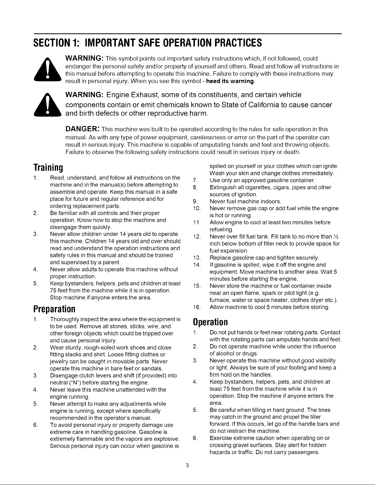
Visit mtdproducts.com for many useful suggestions. Click on Customer Support button and
you will get the four options reproduced here. Click on the appropriate button and help is
immediately available.
answer you are
looking for could be just
" f
a mouse c//cA awayf
answer are
looking for could be just
" f
a mouse c//cA awayf
If you prefer to reach a Customer Support Representative, please call 1-800-800-7310.
The engine manufacturer is responsible for all engine-related issues with regards to
performance, power-rating, specifications, warranty and service. Please refer to the engine
manufacturer's Owner's/Operator's Manual, packed separately with your unit, for more
information.
SECTION1: IMPORTANTSAFEOPERATIONPRACTICES
WARNING: This symbol points out important safety instructions which, if not followed, could
endanger the personal safety and/or property of yourself and others. Read and follow all instructions in
this manual before attempting to operate this machine. Failure to comply with these instructions may
result in personal injury. When you see this symbol - heed its warning.
WARNING: Engine Exhaust, some of its constituents, and certain vehicle
components contain or emit chemicals known to State of California to cause cancer
and birth defects or other reproductive harm.
DANGER: This machine was built to be operated according to the rules for safe operation in this
manual. As with any type of power equipment, carelessness or error on the part of the operator can
result in serious injury. This machine is capable of amputating hands and feet and throwing objects.
Failure to observe the following safety instructions could result in serious injury or death.
Training
1. Read, understand, and follow all instructions on the
machine and in the manual(s) before attempting to
assemble and operate. Keep this manual in a safe
place for future and regular reference and for
ordering replacement parts.
2. Be familiar with all controls and their proper
operation. Know how to stop the machine and
disengage them quickly.
3. Never allow children under 14 years old to operate
this machine. Children 14 years old and over should
read and understand the operation instructions and
safety rules in this manual and should be trained
and supervised by a parent.
4. Never allow adults to operate this machine without
proper instruction.
5. Keep bystanders, helpers, pets and children at least
75 feet from the machine while it is in operation.
Stop machine if anyone enters the area.
Preparation
1. Thoroughly inspect the area where the equipment is
to be used. Remove all stones, sticks, wire, and
other foreign objects which could be tripped over
and cause personal injury.
2. Wear sturdy, rough-soled work shoes and close
fitting slacks and shirt. Loose fitting clothes or
jewelry can be caught in movable parts. Never
operate this machine in bare feet or sandals.
3. Disengage clutch levers and shift (if provided) into
neutral CN") before starting the engine.
4. Never leave this machine unattended with the
engine running.
5. Never attempt to make any adjustments while
engine is running, except where specifically
recommended in the operator's manual.
6. To avoid personal injury or property damage use
extreme care in handling gasoline. Gasoline is
extremely flammable and the vapors are explosive.
Serious personal injury can occur when gasoline is
spilled on yourself or your clothes which can ignite.
Wash your skin and change clothes immediately.
7. Use only an approved gasoline container.
8. Extinguish all cigarettes, cigars, pipes and other
sources of ignition.
9. Never fuel machine indoors.
10. Never remove gas cap or add fuel while the engine
is hot or running.
11. Allow engine to cool at least two minutes before
refueling.
12. Never over fill fuel tank. Fill tank to no more than ½
inch below bottom of filler neck to provide space for
fuel expansion.
13. Replace gasoline cap and tighten securely.
14. Ifgasoline is spilled, wipe it offthe engine and
equipment. Move machine to another area. Wait 5
minutes before starting the engine.
15. Never store the machine or fuel container inside
near an open flame, spark or pilot light (e.g.
furnace, water or space heater, clothes dryer etc.).
16. Allow machine to cool 5 minutes before storing.
Operation
1. Do not put hands or feet near rotating parts. Contact
with the rotating parts can amputate hands and feet.
2. Do not operate machine while under the influence
of alcohol or drugs.
3. Never operate this machine without good visibility
or light. Always be sure of your footing and keep a
firm hold on the handles.
4. Keep bystanders, helpers, pets, and children at
least 75 feet from the machine while it is in
operation. Stop the machine if anyone enters the
area.
5. Be careful when tilling in hard ground. The tines
may catch in the ground and propel the tiller
forward. If this occurs, let go of the handle bars and
do not restrain the machine.
6. Exercise extreme caution when operating on or
crossing gravel surfaces. Stay alert for hidden
hazards or traffic. Do not carry passengers.

7. Neveroperatethemachineathightransport
speedsonhardorslipperysurfaces.
8. Exercisecautiontoavoidslippingorfalling.
9. Lookdownandbehindandusecarewhenin
reverseorpullingmachinetowardsyou.
10. Starttheengineaccordingtotheinstructionsfound
inthismanualandkeepfeetwellawayfromthe
tinesatalltimes.
11. Afterstrikingaforeignobject,stoptheengine,
disconnectthesparkplugwireandgroundagainst
theengine.Thoroughlyinspectthemachineforany
damage.Repairthedamagebeforestartingand
operating.
12. Disengageallclutchleversandstopenginebefore
youleavetheoperatingposition(behindthe
handles).Waituntilthetinescometoacomplete
stopbeforeuncloggingthetines,makingany
adjustments,orinspections.
13. Neverrunanengineindoorsorinapoorly
ventilatedarea.Engineexhaustcontainscarbon
monoxide,anodorlessanddeadlygas.
14. Mufflerandenginebecomehotandcancausea
burn.Donottouch.
15. Usecautionwhentillingnearfences,buildingsand
undergroundutilities.Rotatingtinescancause
propertydamageorpersonalinjury.
16. Donotoverloadmachinecapacitybyattemptingto
tillsoiltodeepattofastofarate.
17. Ifthemachineshouldstartmakinganunusualnoise
orvibration,stoptheengine,disconnectthespark
plugwireandgrounditagainsttheengine.Inspect
thoroughlyfordamage.Repairanydamagebefore
startingandoperating.
18. Keepallshields,guardsandsafetydevicesinplace
andoperatingproperly.
19. Neverpickuporcarrymachinewhiletheengineis
running.
20. Useonlyattachmentsandaccessoriesapprovedby
themanufacturer.Failuretodoso,canresultin
personalinjury.
21. Ifsituationsoccurwhicharenotcoveredinthis
manual,usecareandgoodjudgment.Contactyour
dealerortelephone1-800-800-7310forassistance
andthenameofyournearestservicingdealer.
Maintenance& Storage
1. Never tamper with safety devices. Check their
proper operation regularly.
2. Check bolts and screws for proper tightness at
frequent intervals to keep the machine in safe
working condition. Also, visually inspect machine for
any damage.
3. Before cleaning, repairing, or inspecting, stop the
engine and make certain the tines and all moving
parts have stopped. Disconnect the spark plug wire
and ground it against the engine to prevent
unintended starting.
4.
5.
6.
7.
8.
9.
10.
Do not change the engine governor settings or
over-speed the engine. The governor controls the
maximum safe operating speed of the engine.
Maintain or replace safety and instruction labels, as
necessary.
Follow this manual for safe loading, unloading,
transporting, and storage of this machine.
Never store the machine or fuel container inside
where there is an open flame, spark or pilot light
such as a water heater, furnace, clothes dryer etc.
Always refer to the operator's manual for proper
instructions on off-season storage.
Ifthe fuel tank has to be drained, do this outdoors.
Observe proper disposal laws and regulations for
gas, oil, etc. to protect the environment.
YourResponsibility
1. Restrict the use of this power machine to persons
who read, understand and follow the warnings and
instructions in this manual and on the machine.
2. The safety label on the tiller is reproduced below for
your review. To ensure safe operation of the tiller,
follow the instructions on all labels closely.

SECTION2: ASSEMBLINGYOURTILLER
NOTE: This operator's manual covers various models
of tillers. The units illustrated may vary slightly from
your unit. Follow only those instructions which pertain
to your model number.
NOTE: References to right or left side of the tiller are
determined from behind the unit in the operating
position.
ToRemoveUnitFromCarton
• Remove staples, break glue on top flaps, or cut
tape at carton end and peel along top flap to open
carton.
• Remove loose parts included with unit (i.e.,
operator's manual, etc.).
• Cut corners and lay carton down flat.
• Remove packing material.
• Roll or slide unit out of carton. Check carton
thoroughly for loose parts.
• Extend control cable and lay on the floor. Be careful
not to bend or kink control cable.
IMPORTANT:This unit is shipped without gasoline or oil
in the engine. Be certain to service engine with gasoline
and oil as instructed in the separate engine manual
before operating your machine.
LoosePartsInCarton
Depth Stake
Handle Assembly
Shift Rod
Handle Adjustment Rod (Model series 420 only)
NOTE: All hardware needed for assembly is attached
to the loose parts or the tiller.
BeforeAssembly
WARNING: Disconnect the spark plug wire
and ground it against the engine to prevent
unintended starting.
AttachingDepthStake
• Tip the tiller forward so it rests on front
counterweight.
• Unthread the "T" knob from the top of the depth
stake and remove the flat washer and hex bolt.
Remove the hairpin clip from the clevis pin.
See Figure 1.
• Raise the tine shield hinge flap assembly and insert
the depth stake assembly in the slot (under the tine
shield) and up through the tine shield assembly.
• Insert clevis pin through the tine shield and depth
stake assemblies. Secure with hairpin clip.
Insert hex bolt into the top hole of the depth stake
assembly. Place flat washer on the hex bolt and
thread "T" knob onto the hex bolt. Tighten securely.
See Figure 1.
Tip the tiller back down so it rests on the tines.
Clevis Pin
Depth Stake
Flat Washer Hex Bolt
T-Knob
rpin Clip
Figure 1
AttachingHandleAssembly
• Remove the handle adjustment crank, flange nut,
retainer bracket, shoulder bolt, and lock nut from
the pivot bracket.
• Place the handle assembly in position in the handle
pivot bracket lining the upper holes in the handle
with the slots in the pivot bracket. See Figure 2.
Retainer Bracket,
Shoulder Bolt, & Lock Nut
Handle Adjustment Crank j
and Flange Nut_ /
Pivot Bracket
Figure 2
Lift up the handle assembly and align the bottom
holes in the handle assembly with the holes in the
pivot bracket. Insert shoulder bolt from the left side
of unit through the pivot bracket and the retainer
bracket on the right hand side of the unit.
See Figure 3.
Retainer Bracket
Shoulder Bolt & Lock Nut
Figure 3
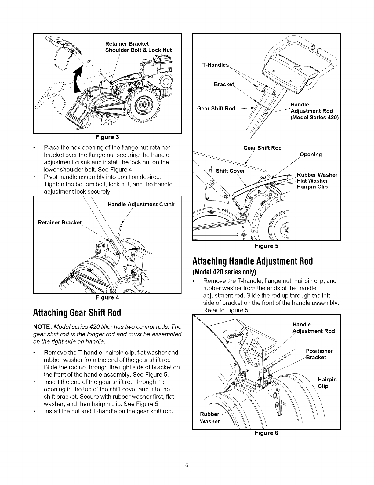
• Place the hex opening of the flange nut retainer
bracket over the flange nut securing the handle
adjustment crank and install the lock nut on the
lower shoulder bolt. See Figure 4.
• Pivot handle assembly into position desired.
Tighten the bottom bolt, lock nut, and the handle
adjustment lock securely.
Handle Ad ustment Crank
Retainer Bracket
Gear
Gear Shift Rod
/
Handle
ustment Rod
(Model Series 420)
Rubber Washer
-lat Washer
Hairpin Clip
Figure 4
AttachingGearShiftRod
NOTE: Model series 420 tiller has two control rods. The
gear shift rod is the longer rod and must be assembled
on the right side on handle.
• Remove the T-handle, hairpin clip, flat washer and
rubber washer from the end of the gear shift rod.
Slide the rod up through the right side of bracket on
the front of the handle assembly. See Figure 5.
• Insert the end of the gear shift rod through the
opening in the top of the shift cover and into the
shift bracket. Secure with rubber washer first, flat
washer, and then hairpin clip. See Figure 5.
• Install the nut and T-handle on the gear shift rod.
Figure 5
AttachingHandleAdjustmentRod
(Model420 seriesonly)
• Remove the T-handle, flange nut, hairpin clip, and
rubber washer from the ends of the handle
adjustment rod. Slide the rod up through the left
side of bracket on the front of the handle assembly.
Refer to Figure 5.
Handle
Adjustment Rod
Positioner
Rubber
Washer
Figure 6
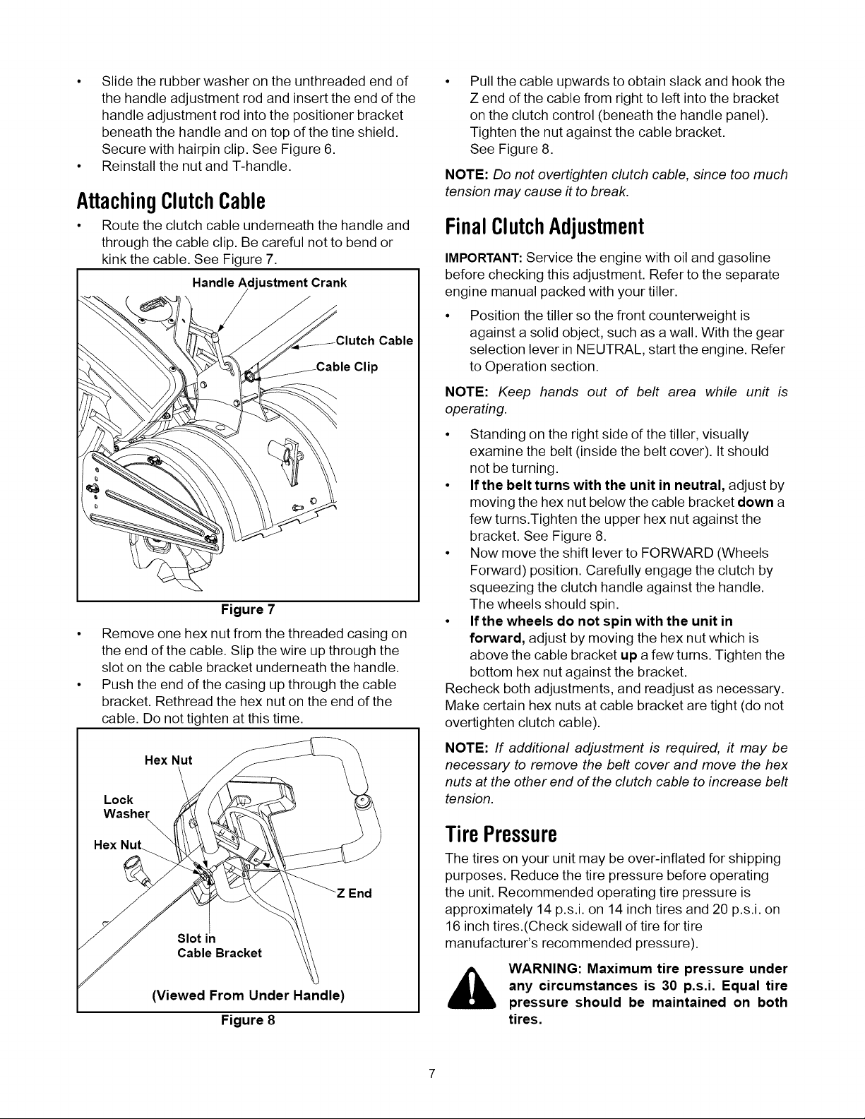
• Slide the rubber washer on the unthreaded end of
the handle adjustment rod and insert the end of the
handle adjustment rod into the positioner bracket
beneath the handle and on top of the tine shield.
Secure with hairpin clip. See Figure 6.
• Reinstall the nut and T-handle.
AttachingClutchCable
• Route the clutch cable underneath the handle and
through the cable clip. Be careful not to bend or
kink the cable. See Figure 7.
Handle Adjustment Crank
Cable
Clip
Figure 7
• Remove one hex nut from the threaded casing on
the end of the cable. Slip the wire up through the
slot on the cable bracket underneath the handle.
• Push the end of the casing up through the cable
bracket. Rethread the hex nut on the end of the
cable. Do not tighten at this time.
Hex Nut
\
Lock
Washer
\
Hex
End
Slot in
Cable Bracket
(Viewed From Under Handle)
Figure 8
Pull the cable upwards to obtain slack and hook the
Z end of the cable from right to left into the bracket
on the clutch control (beneath the handle panel).
Tighten the nut against the cable bracket.
See Figure 8.
NOTE: Do not overtighten clutch cable, since too much
tension may cause it to break.
FinalClutchAdjustment
IMPORTANT:Service the engine with oil and gasoline
before checking this adjustment. Refer to the separate
engine manual packed with your tiller.
Position the tiller so the front counterweight is
against a solid object, such as a wall. With the gear
selection lever in NEUTRAL, start the engine. Refer
to Operation section.
NOTE: Keep hands out of belt area while unit is
operating.
• Standing on the right side of the tiller, visually
examine the belt (inside the belt cover). It should
not be turning.
• Ifthe belt turns with the unit in neutral, adjust by
moving the hex nut below the cable bracket down a
few turns.Tighten the upper hex nut against the
bracket. See Figure 8.
• Now move the shift lever to FORWARD (Wheels
Forward) position. Carefully engage the clutch by
squeezing the clutch handle against the handle.
The wheels should spin.
• If the wheels do not spin with the unit in
forward, adjust by moving the hex nut which is
above the cable bracket up a few turns. Tighten the
bottom hex nut against the bracket.
Recheck both adjustments, and readjust as necessary.
Make certain hex nuts at cable bracket are tight (do not
overtighten clutch cable).
NOTE: If additional adjustment is required, it may be
necessary to remove the belt cover and move the hex
nuts at the other end of the clutch cable to increase belt
tension.
TirePressure
The tires on your unit may be over-inflated for shipping
purposes. Reduce the tire pressure before operating
the unit. Recommended operating tire pressure is
approximately 14 p.s.i, on 14 inch tires and 20 p.s.i, on
16 inch tires.(Check sidewall of tire for tire
manufacturer's recommended pressure).
WARNING: Maximum tire pressure under
any circumstances is 30 p.s.i. Equal tire
pressure should be maintained on both
tires.

SECTION3: KNOWYOURTILLER
Gear Selection __ Clutch
Handle "_......__ Gear Shift Rod
Handle
Adjustment Cran
Stake
\Handle
Adjustment Rod
Model 420 Series
Model 410 Series
Figure 9
_, WARNING: Read, understand, and follow
all instructions and warnings on the
machine and in this manual before
operating.
Reverse
Reverse wheel drive only.
Neutral
Transmission is in neutral.
GearSelectionHandle
The gear selection handle is located on the front of the
handle assembly (right handle on Model 420 Series). It
is used to select NEUTRAL, REVERSE, orone of the
FORWARD modes.
This tiller is designed for the gear selection handle to be
moved while the engine is running. (It will be difficult to
obtain all four positions with the engine off.) Pull or push
the handle so that the indicator on top of shift cover
points to the area of the operating mode desired.
See Figure 9.
NOTE: If difficulty is encountered in moving the gear
selection handle, refer to the following helpful hints:
• To shift into forward or reverse wheel drive, move
tiller forward slightly then backward to allow the
gears to synchronize.
• To shift into forward wheels and tine drive, push
forward slightly on the gear selection handle and
slowly engage the clutch handle allowing the gears
to synchronize.
• To stop forward movement and tine drive, release
the clutch handle. Do not shift gears with the clutch
handle engaged except when engaging the tines.
WheelsForward
Forward wheel drive only.
Tines Reverse
Forward wheel drive and reverse tine drive.
,_ WARNING: Make certain unit
NEUTRAL when starting the engine.
is in
ClutchHandle
The clutch handle is located beneath the handle.
Squeezing the clutch handle against the handle
engages the wheel and tine drive mechanisms.
See Figure 9.
ThrottleControl
The throttle control lever is located on the engine. It
controls the engine speed and stops the engine.
ChokeLever(IfEquipped)
The choke lever is located by the throttle. It is used to
enrich the fuel mixture in the carburetor when starting a
cold engine.
 Loading...