


To The Owner • Carton Contents • Assembly • Parts Lists • Warranty
OPERATOR’S MANUAL
Twin Rear Bagger Kit
For Lawn Tractors
Model 190-180 & 190-182
IMPORTANT
READ SAFETY RULES AND INSTRUCTIONS CAREFULLY BEFORE OPERATION
|
|
FORM NO. 769-03178 |
PRINTED IN U.S.A. |
MTD LLC, P.O. BOX 361131 CLEVELAND, OHIO 44136-0019 |
4/3/2007 |
This Operator’s Manual is an important part of your new grass collector. It will help you assemble, prepare and maintain the unit for best performance. Please read and understand what it says.
TABLE OF CONTENTS
1. Rider Identification............................................ |
Page 3 |
6. Attach Discharge Chute.................................. |
Page 10 |
|
2. |
Carton Contents............................................... |
Page 4 7. Parts List........................................................... |
Page 12 |
|
3. |
Bracket Assembly............................................ |
Page 6 |
Spanish Section................................................... |
Page 14 |
4. Attach Grass Bags........................................... |
Page 8 |
French Section..................................................... |
Page 25 |
|
5. |
Attaching Blades (46” Deck Models only)........ |
Page 9 |
|
|
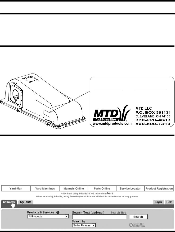
Finding and Recording Model Number
BEFORE YOU START ASSEMBLING YOUR NEW EQUIPMENT,
please locate the model plate and copy the information from it in this Operator’s Manual for future reference. The information on the model plate is very important if you need help from our Customer Support Department or your authorized dealer.
You can locate it by looking on the front, left portion of the plastic grass catcher cover as seen below:
Model Number |
Serial Number |
*Locate the model plate on your bagger and copy the information from it in the space provided above for future reference.
Customer Support
Please do NOT return the unit to the retailer from which it was purchased, without first contacting Customer Support.
If you have difficulty assembling this product or have any questions regarding the controls, operation, or maintenance of this unit, you can seek help from the experts. Choose from the options below:
•Visit www.mtdproducts.com. Click on the Service & Support menu option.
•Phone a Customer Support Representative at 1-800-800-7310.
•Please have your unit’s model number and serial number ready when you call. See above to locate this information. You will be asked to enter the serial number in order to process your call.
Model Plate
1 |
30 |
3 |
81 |
11 |
63 |
6 |
47 |
C3 |
-00- |
LLX |
20 |
OB |
28 |
DT. |
-00- |
O. |
30 |
MP |
38 |
Figure 1-1
Sample Model Number
1 3 A M 7 9 0 G 0 0 0
Indicates Model Series 700
Figure 1-2
FastAttach™ Twin Bag
Grass Collector
The Model 190-180 and 190-182 Twin Bag Grass Collector is a grass collection system designed for use on all MTD 38”, 42” and 46” lawn tractors.
The instructions in this manual are divided into sections. Carefully read all sections pertaining to your model of rider, and study the illustrations to ensure proper installation and usage of this attachment. Read and observe all WARNING, NOTES and IMPORTANT statements. They are included to provide for the protection of the equipment installer and user, and to ensure the prolonged service life of the equipment.
NOTE: References to LEFT and RIGHT indicate the left and right sides of the tractor when facing forward in the operator’s position. Reference to the FRONT indicates the grille end; to the REAR, the rear end of the rider.
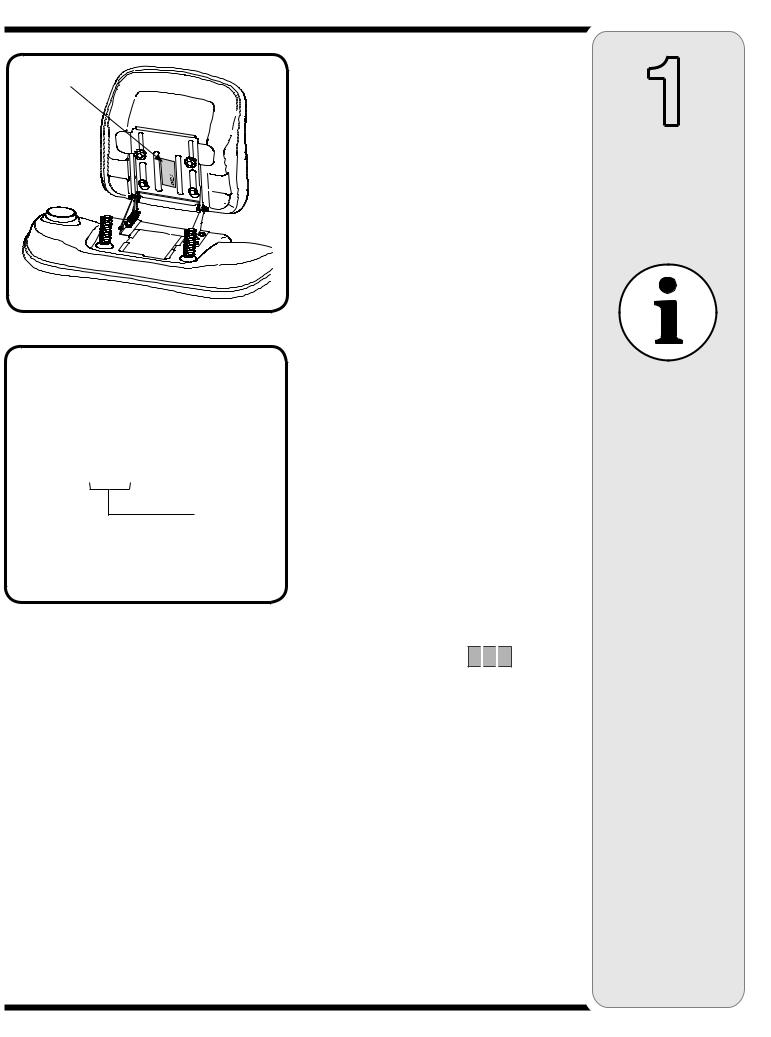
Determine The Model
of Your Rider
Since this manual is designed for installation of your new bagger on several different rider units, it is important
for you to determine which model of rider you have. Therefore you will know which set of instructions in the following pages to follow.
To determine which model of rider you have, you will need to locate the rider’s model plate, located under the seat, as in Fig. 1-1. Simply flip the seat up and locate the model plate, which will consist of an 11 digit/letter model number and a serial number. For ease in this installation and for future use, copy your rider’s model number & serial number below now:
Rider Model Number:__ __ __ __ __
 __
__
 __ __ __ __ __
Rider Serial Number:_________________________
The 5th, 6th & 7th numbers from the left in your model number determine your rider’s model series. See Fig. 1-2.
When you fill in your model number in the space above, the actual model series number should fall into the gray shaded area.
Now that you have determined what model rider you are attaching this grass bag collection system to, follow the instructions on the following pages according to your model of rider.
1
Rider Model Identification
NOTE:
References to LEFT and RIGHT indicate the left and right sides of the tractor when facing forward in the operator’s position. Reference to the FRONT indicates the grille end; to the REAR, the rear end of the rider.
2
Carton
Contents
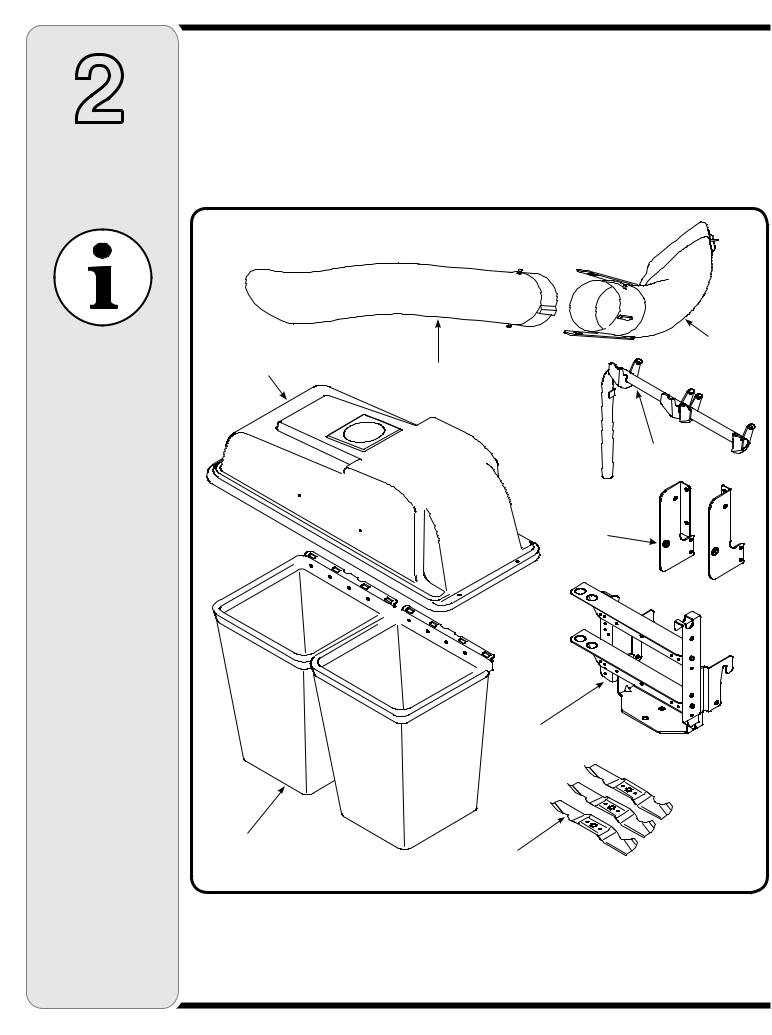
CONTENTS OF CARTON
Before beginning installation, remove all parts from the carton to make sure everything is present. Carton contents are listed below and shown in Fig. 2-1.
One Chute Tube
One Discharge Chute Assembly Two Grass Bag Assemblies Grass Catcher Support Brackets
If you are missing any parts, please do not contact the retailer where you purchased this unit, call MTD directly at 1-330-220-4MTD or
toll free at 1-800-800-7310.
|
|
Discharge Chute |
Grass Catcher Cover |
Chute Tube |
Assembly |
|
||
Assembly |
|
|
|
|
Support Tube |
|
|
Grass Catcher |
|
|
Support Brackets |
Mounting Bracket Assenmbly
Grass Bag Assemblies
*Blades
Figure 2-1
*Included with Bagger Kits for 46” decks.
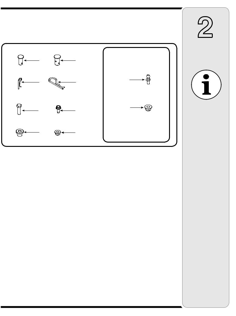
CONTENTS OF HARDWARE PACK
This grass collector kit is shipped with a hardware pack enclosed. This hardware pack may contain extra parts for installation on a different rider from which you have. Please check your hardware pack against the illustration below.
(2) |
A1 |
(1) |
B1* |
|
|
||
(2) |
A2 |
(1) |
B2* |
|
|
(2) |
C1 |
(8) |
D1 |
|
|
||
(2) |
C2 |
(2) |
D2 |
|
|
Figure 2-2
For decks with grass catcher pin not pre-installed
E1 (1)
E2 (1)
(#) = Quantity
NOTE: Each item has been identified above for ease of assembly, and the letter code assigned here is maintained in assembly instructions.
*The clevis pin (B1) and hairpin clip (B2) may come pre-installed in the hitch-plate assembly from the factory. In that case it will not be included in the hardware pack, but pre-installed in the hitch-plate.
2
Carton
Contents
If you are missing any parts, please do not contact the retailer where you purchased this unit, call MTD directly at 1-330-220-4MTD or
toll free at 1-800-800-7310.
NOTE:
Each item has been identified in above for ease of assembly, and the letter code assigned here is maintained in assembly instructions.
(#) = Quantity
3
Attaching Bracket Assembly
Model Series 600
IMPORTANT:
Before assembly, place the tractor on a firm, level surface, disengage the PTO, stop the tractor engine and set the parking brake.
NOTE:
There are two holes in the clevis pin. Be sure to insert the hairpin clip in the upper hole to properly secure the bracket assembly to the hitch plate.
Attaching The Bracket Assembly
Model Series 600
IMPORTANT: Before assembly, place the tractor on a firm, level surface, disengage the PTO, stop the tractor engine and set the parking brake.
1. For convenience, pivot the seat forward and leave it in that position until the grass collector is fully mounted and assembled.
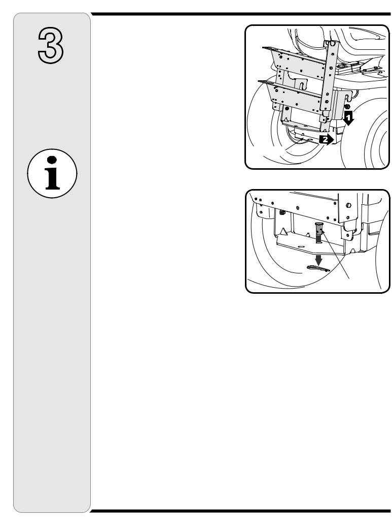
2. Position the hooked ends of the bracket assembly over the shoulder bolts (1). Swing in the bottom of
the bracket assembly down and in (2) over the hitch
plate and aligning with the hole on the hitch plate. Hitch Plate See Fig. 3-1.
3.Insert the clevis pin (B1 in Fig. 2-2) through the aligned holes in both the bracket assembly and the hitch plate and secure with the hairpin clip (B2 in Fig. 2-2). Refer to Figure 3-2.
NOTE: There are two holes in the clevis pin. Be sure to insert the hairpin clip in the upper hole to properly secure the bracket assembly to the hitch plate.
Figure 3-1
Upper Hole
Figure 3-2
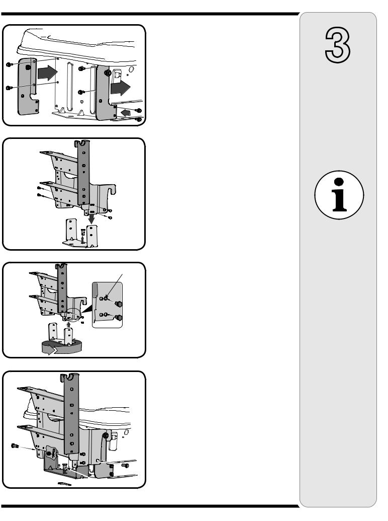
Figure 3-3
Figure 3-4
Inner holes
Figure 3-5
 Upper Hole
Figure 3-6
Assembling Support
Brackets
Model Series 700
1.Locate the eight self-tapping screws supplied in your hardware pack (D1 from Fig. 2-2). Attach the right hand grass catcher support bracket using four of the supplied screws in position as shown in Fig. 3-3. Place the left hand grass catcher support bracket in position and secure with the other four screws.
NOTE: For easier installation, first align and start all four screws in each bracket before tightening.
2.Insert a hex bolt (C1 in Fig. 2-2) through a shoulder spacer, (C2 in Fig. 2-2), and secure with a 3/8” Hex FlangeLock Nut (D2 in Fig. 2-2). Tighten securely.
Repeat on other side.
NOTE: If the grass collection system is removed for any reason, it is not necessary to remove the support brackets from the tractor.
Attaching The Bracket
Assembly
1.Remove the two nuts and screws on each side of the mounting bracket holding the hitch plate. See Fig. 3-4.
NOTE: The clevis pin and hairpin clip may come preinstalled in the hitch-plate from the factory. If this is the case, remove the clevis pin now by removing the hairpin clip and lifitng the clevis pin out as seen in Fig. 3-4.
2.Rotate the hitch plate 180° from its original position. Re-insert the four bolts through mounting bracket and hitch plate frame and secure with nuts removed earlier. Use the inner holes (closest to the mounting hooks) on the mounting bracket. Refer to Fig. 3-5.
3.Position the hooked ends of the mounting bracket assembly to the outside of the support bracket and over the shoulder bolts on both sides. Secure each mounting bracket with a clevis pin (A1 from Fig. 2-2) and hairpin clip (A2 from Fig. 2-2) from the hardware pack. See Fig. 3-6.
4.Insert the clevis pin (B1 in Fig. 2-2) through the aligned holes in both the bracket assembly and the hitch plate and secure with the hairpin clip (B2 in Fig. 2-2). See Fig. 3-6.
IMPORTANT: There are two holes in the clevis pin. Be sure to insert the hairpin clip in the upper hole to properly secure the bracket assembly to the hitch plate.
3
Attaching Support Bracket & Bracket Assembly
Model Series 700
NOTE:
If the grass collection system is removed for any reason, it is not necessary to remove the support brackets from the tractor.
The clevis pin and hairpin clip may come pre-installed in the hitch-plate from the factory. If this is the case, remove the clevis pin now by removing the hairpin clip and lifitng the clevis pin out.
IMPORTANT:
There are two holes in the clevis pin. Be sure to insert the hairpin clip in the upper hole to properly secure the bracket assembly to the hitch plate.

4
Attaching
Grass Bags
& Grass Bag
Cover
All Model Series
600 & 700
NOTE:
Insert the clevis pins from the outside in as shown in the inset images of Fig. 4-4.
NOTE:
It is very important to maintain this order and direction while installing these hardware pieces. After installation, make sure that the grass bag cover pivots on the sup-
port tube and opens.
Attaching Grass Bags &
Grass Bag Cover
1. Place the support tube in position on the rear of unit |
Inside Hole |
by sliding the support tube down through the holes in |
|
the left side of the bracket assembly. Use the inside |
|
hole on the bracket assembly regardless of what size |
|
deck your tractor is equipped with. Refer to Fig. 4-1. |
|
2.Attach the grass bags by hooking them onto the grass bag bracket using the slots in the grass bag and the tabs on the grass bag bracket as shown in Fig. 4-2.
3.Remove both clevis pins, belleville washers and hairpin clips from the hinges of the grassbag cover.
4.Place the grass bag cover on top of the grass bags and align the holes on the hinges of the grass bag cover with the corresponding holes on the support tube assembly. See Fig. 4-3.
5.Reinsert the clevis pins previously removed through the hinge on the support tube assembly and then through the grass bag cover. See Fig. 4-4.
6.Secure with belleville washer and hairpin clip with the crown side of the washer going against the hairpin clip. See inset images in Fig. 4-4.
7.Repeat with the second set of hardware through the second hinge of the grass bag and the tube assembly from the opposite direction.
NOTE: Insert the clevis pins from the outside in as shown in the inset images of Figure 4-4.
NOTE: It is very important to maintain this order and direction while installing these hardware pieces. After installation, make sure that the grass bag cover pivots on the support tube and opens.
Figure 4-4
Figure 4-1
Figure 4-2
Figure 4-3
Smaller Blade
Part No. 742-0645
|
|
Attaching The Blades |
|
|
NOTE: If your tractor is equipped with a 46” cutting deck, |
||
|
three 2-in-1 cutting blades are included with this kit. For |
||
|
improved bagging performance, install these blades on |
||
|
your tractor using the following instructions. |
||
|
Remove the blades from your tractor’s cutting deck as |
||
|
follows: |
||
|
1. |
Remove the cutting deck from beneath the tractor, |
|
|
Larger Blades |
(refer to Deck Removal in the MAINTENANCE |
|
Hex Flange Nut |
Part No. 742-0644 |
section of your tractor’s operator’s manual for detailed |
|
|
instructions) then gently flip the deck over to expose |
||
|
|
||
Figure 5-1 |
|
its underside. |
|
2. |
Place a block of wood between the center deck hous- |
||
|
|||
|
|
ing baffle and the cutting blade to act as a stabilizer, |
|
|
|
keeping the blades from turning when you loosen the |
|
|
|
hex flange nuts. |
|
|
3. |
Use a 15/16” wrench to remove the hex flange nut that |
|
|
|
secures the blade to the spindle assembly. |
|
NOTE: The hex flange nut has a normal (right-handed) thread pattern. Do NOT attempt to force the nut in the incorrect direction. Doing so may damage the nut and create a safety hazard.
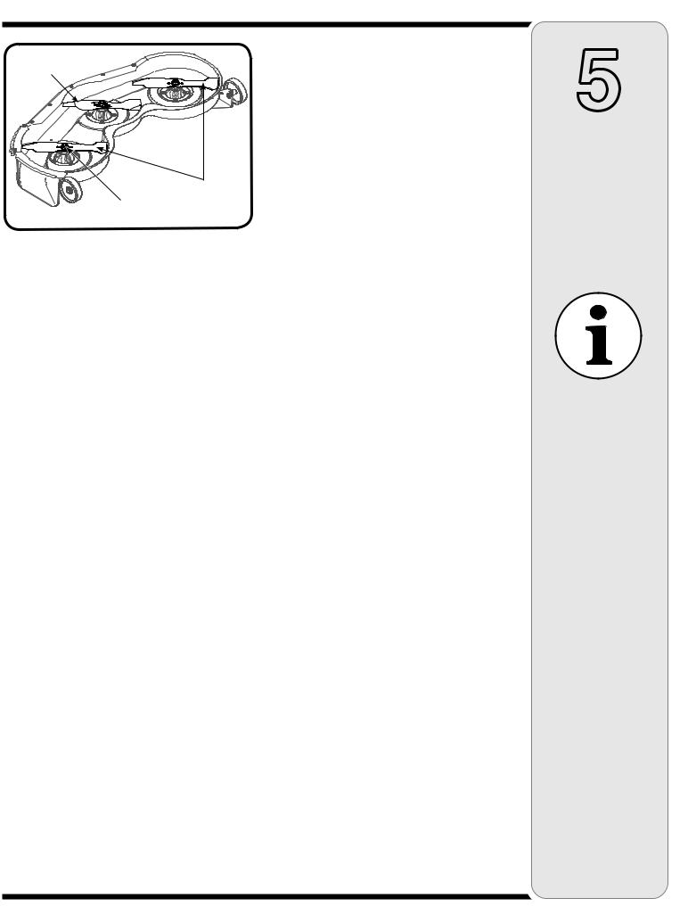
4.Install the new blades packed with the bagger. Be sure to install the blade with the side of the blade marked ‘‘Bottom’’ (or with a part number stamped in it) facing the ground when the rider is in the operating position.
5.Mount the SMALLER of the three blades to the CENTER spindle. The remaining two blades are interchangeable. See Fig. 5-1.
6.Use a torque wrench to tighten the blade spindle hex flange nut to between 70 and 90 foot-pounds.
7.Remount the cutting deck.
5
Attaching
The Blades
46-Inch Cutting
Deck Models Only
NOTE:
If your tractor is equipped with a 46” cutting deck, three 2-in-1 cutting blades are included with this kit. For proper bagging performance, install these blades on your tractor using the following instructions.
NOTE:
The hex flange nut has a normal (righthanded) thread pattern. Do NOT attempt to force the nut in the incorrect direction. Doing so may damage the nut and create a safety hazard.
6
Attaching Discharge
Chute
All Model Series
NOTE:
The retainer strap is fitted at position A on the discharge chute.
However, on older models of tractors, you will have to change the position of the strap depending on the location of the grass catcher pin on the deck. Remove the retainer strap from position A on the discharge chute to position B or C corresponding to the position of the grass catcher pin at A, B or C on the deck. See Fig. 6-3.
Attaching Discharge
Chute
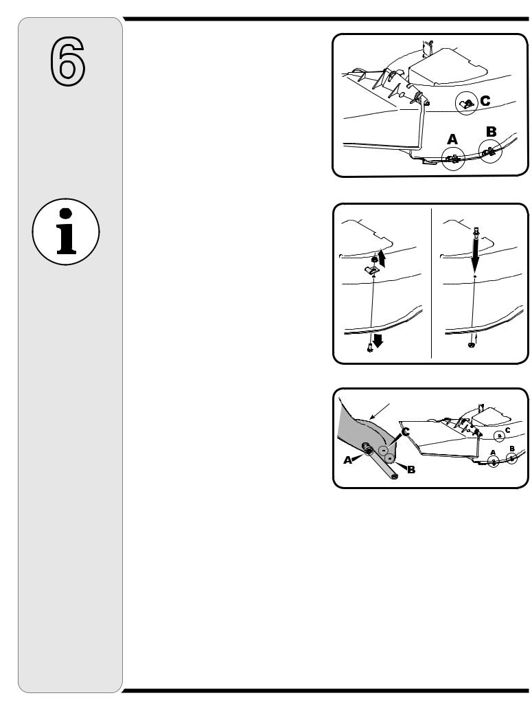
1.On some older models, a clip is already installed on the cutting deck next to the discharge chute opening in position A, B, or C, as seen in Fig. 6-1. If this is the case, the clip must be removed and a grass catcher pin installed.
2.Pin Installation: A grass catcher pin (E1 in Fig. 2-2) and nut (E2 in Fig. 2-2) have been supplied in the hardware pack. First remove the clip (if present), as seen in Fig. 6-2A, by removing the nut and bolt. Then attach the grass catcher pin as seen in Fig. 6-2B. Make sure to secure the pin tightly.
3.Some units may not have clip, but will have an open hole for pin installation. In this case, install the grass catcher pin from the hardware pack in the available hole.
4.You will then need to position the retainer strap on the discharge chute to correspond with the hole and pin. See Fig. 6-3 for retainer strap positioning.
NOTE: The retainer strap is fitted at position A on the discharge chute. However, on older models of tractors, you will have to change the position of the strap depending on the location of the grass catcher pin on the deck. Remove the retainer strap from position A on the discharge chute to position B or C corresponding to the position of the grass catcher pin at A, B or C on the deck. See Fig. 6-3.
Figure 6-1
A B
Figure 6-2
Discharge Chute
Figure 6-3
10
Retainer Strap
Grass Catcher Pin
Figure 6-4
Figure 6-5
Tab 
Figure 6-6
Attaching Discharge
Chute
All Model Series
1.Raise the deck to its highest position.
2.Raise the chute deflector on the deck and hold it while you position the discharge chute over the chute opening.
3.Place the top rear edge of the discharge chute over the top rear edge of the chute opening.
4.Push down on the discharge chute so that its front bottom edge rolls around the bottom of the deck, then slide the chute forward to the stop on the deck. See Fig. 6-4.
5.Lock the discharge chute in position by hooking the retainer strap over the grass catcher pin on the deck. See Fig. 6-4.
6.Insert the curved end of chute tube into the hole in the grass bag cover. See Fig. 6-5.
7.Place the lower end of the chute tube over the discharge chute so that the tabs on the discharge chute fits into the pockets on the chute tube. See Fig. 6-6.
8.Secure by hooking the two retainer straps of the discharge chute to the pins on the chute tube. See Fig. 6-6.
Bagger Usage
All Model Series
NOTE: When both grass bags are full, place the tractor on a firm, level surface, disengage the PTO, turn the tractor engine off and set the parking brake.
1.Flip Seat up.
2.Lift up grass bag cover. Do not remove the chute tube assembly from the tractor.
3.Remove the grass bags by lifting these up and moving the bags away from the support tube assembly.
4.Empty the grass clippings at a proper disposal sight, use the handle at the bottom of each grass bag. Holding the bag firmly, empty the contents
5.Replace grass bags, close lid, flip down seat, restart your tractor and resume cutting your grass.
6
Attaching Discharge
Chute
All Model Series
NOTE:
When both grass
bags are full, place the tractor on a firm, level surface, disengage the PTO, turn the tractor engine off and set the parking brake.
11
 Loading...