How it Works
Log In / Sign Up
0
My Files
0
My Downloads
185566
History
Account Settings
Log Out
Buy Points
How it Works
FAQ
Contact Us
Questions and Suggestions
Users
show menu
MTD
Loading...
#
124-487D000
124-573-000
124-848C000
125-135E000
125-202-000
125-281C000
125-290A
125-487G000
127-280-300
128-266R000
128-465R000
129-282R000
129-459R000
129-474R000
129-838R401
12AKD3X
130
130-452E000
130-466-300
131-510-000
131-808H000
132-395
132-466A
132-475
133-430
133-460
134-723-000
134-796-000
135-470A
135-704-000
136-702-000
137-380A
137-435A
137-495a
137-514-000
137-657-000
137-697-000
137-723-000
138-320-000
138-511-000
138-600-000
138-698-000
138-722-000
139-320-000
13A1762F029
13AB775S000
2
13AC762F729
13AG601H729
13AH451F352
13AJ771G031
13AL771H029
13AL795H004
13AM660F062
13AM660G700
13AQ698G131
13AX604G402
13BH670F062
13BQA1ZT299
13RN771H729
13WJ771S031
140
140-760 14 HP
140-842-000
141-669
141-760 10 HP
144-826-000
144-860A
144-995-000
145-760A
145-810-000
146-760A
146-822-000
146-842-000
147-842-000
148-665
148-807-000
14A7A3ZW099
15HP Z-FORCE 44
1842
186-407-000
18M
190-032-101
190-182
190-678
190-833-OEM
190-940-000
191-935a
194700
208cc
214-381-000
21A-240D731
21AA414A752
235
244-645A000
24AD598A010
25B-550A729
25B-550D229
26J
310-440-000
31A-240-800
Loading...
Loading...
Nothing found
13AL771H029
Owner’s Manual
64 pgs
9.17 Mb
1
Table of contents
Loading...
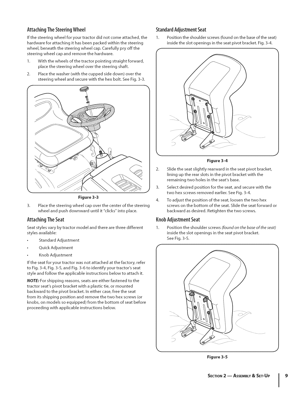
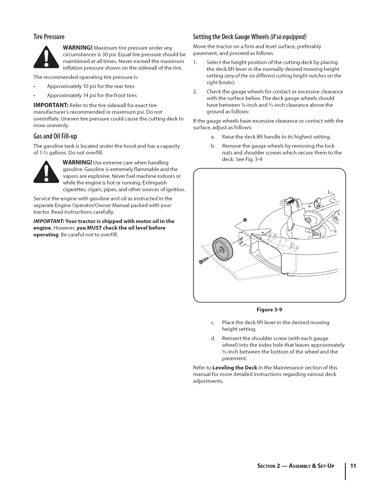
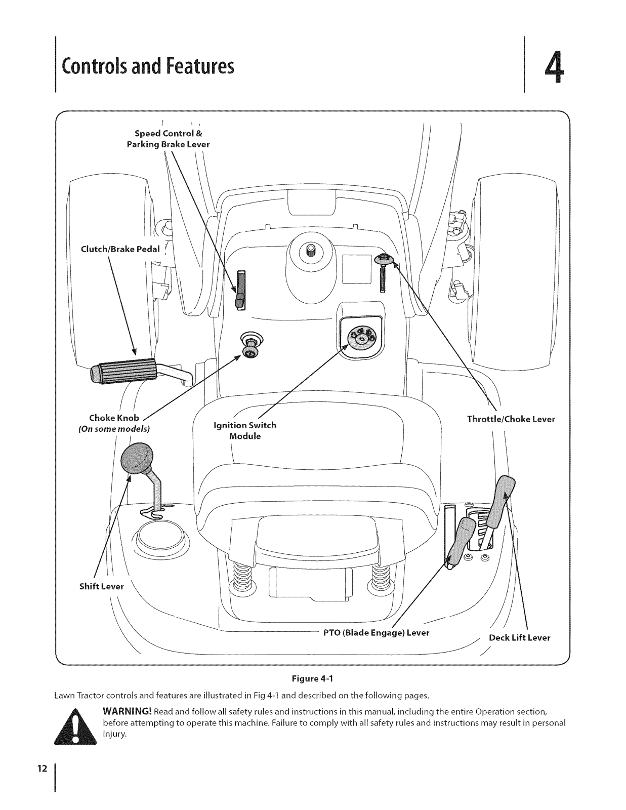
MTD 13AL771H029, 13RN772G229, 13RN772G029, 13RL771H029, 13AN772G029 Owner’s Manual
...
MTD 13AL771H029, 13RN772G229, 13RN772G029, 13RL771H029, 13AN772G029, 13AM762F052, 13AC762F029 Owner’s Manual
Download
4
(
2
)
Loading...
+
44
hidden pages
Unhide
You need points to download manuals.
1 point = 1 manual.
You can buy points or you can get point for every manual you upload.
Buy points
Upload your manuals


 Loading... Loading...